delta t products
TRANSCRIPT

Rev: 11/02/21
DELTA PRODUCTST
DUCTILE IRON 050/051 SERIES STAINLESS STEEL 650/651 SERIES BUTTERFLY VALVES 2”–24” 200/150 PSI Bi-Directional Service, Up to 48” Available
2Rev: 11/02/21
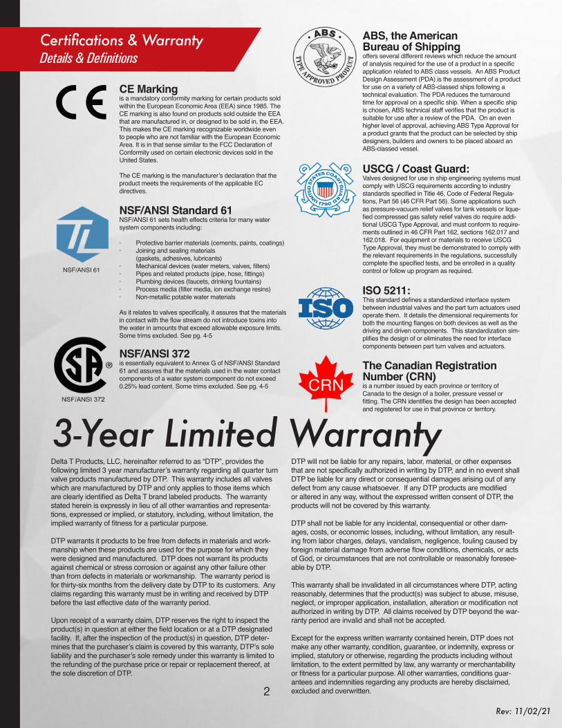
NSF/ANSI 61
CE Marking is a mandatory conformity marking for certain products sold within the European Economic Area (EEA) since 1985. The CE marking is also found on products sold outside the EEA that are manufactured in, or designed to be sold in, the EEA. This makes the CE marking recognizable worldwide even to people who are not familiar with the European Economic Area. It is in that sense similar to the FCC Declaration of Conformity used on certain electronic devices sold in the United States.
The CE marking is the manufacturer’s declaration that the product meets the requirements of the applicable EC directives.
NSF/ANSI Standard 61NSF/ANSI 61 sets health effects criteria for many water system components including:
· Protective barrier materials (cements, paints, coatings)· Joining and sealing materials (gaskets, adhesives, lubricants)· Mechanical devices (water meters, valves, filters)· Pipes and related products (pipe, hose, fittings)· Plumbing devices (faucets, drinking fountains)· Process media (filter media, ion exchange resins)· Non-metallic potable water materials
As it relates to valves specifically, it assures that the materials in contact with the flow stream do not introduce toxins into the water in amounts that exceed allowable exposure limits.Some trims excluded. See pg. 4-5
NSF/ANSI 372is essentially equivalent to Annex G of NSF/ANSI Standard 61 and assures that the materials used in the water contact components of a water system component do not exceed 0.25% lead content. Some trims excluded. See pg. 4-5
ABS, the American Bureau of Shippingoffers several different reviews which reduce the amount of analysis required for the use of a product in a specific application related to ABS class vessels. An ABS Product Design Assessment (PDA) is the assessment of a product for use on a variety of ABS-classed ships following a technical evaluation. The PDA reduces the turnaround time for approval on a specific ship. When a specific ship is chosen, ABS technical staff verifies that the product is suitable for use after a review of the PDA. On an even higher level of approval, achieving ABS Type Approval for a product grants that the product can be selected by ship designers, builders and owners to be placed aboard an ABS-classed vessel.
USCG / Coast Guard:Valves designed for use in ship engineering systems must comply with USCG requirements according to industry standards specified in Title 46, Code of Federal Regula-tions, Part 56 (46 CFR Part 56). Some applications such as pressure-vacuum relief valves for tank vessels or lique-fied compressed gas safety relief valves do require addi-tional USCG Type Approval, and must conform to require-ments outlined in 46 CFR Part 162, sections 162.017 and 162.018. For equipment or materials to receive USCG Type Approval, they must be demonstrated to comply with the relevant requirements in the regulations, successfully complete the specified tests, and be enrolled in a quality control or follow up program as required.
ISO 5211:This standard defines a standardized interface system between industrial valves and the part turn actuators used operate them. It details the dimensional requirements for both the mounting flanges on both devices as well as the driving and driven components. This standardization sim-plifies the design of or eliminates the need for interface components between part turn valves and actuators.
The Canadian Registration Number (CRN)is a number issued by each province or territory of Canada to the design of a boiler, pressure vessel or fitting. The CRN identifies the design has been accepted and registered for use in that province or territory.
Delta T Products, LLC, hereinafter referred to as “DTP”, provides the following limited 3 year manufacturer’s warranty regarding all quarter turn valve products manufactured by DTP. This warranty includes all valves which are manufactured by DTP and only applies to those items which are clearly identified as Delta T brand labeled products. The warranty stated herein is expressly in lieu of all other warranties and representa-tions, expressed or implied, or statutory, including, without limitation, the implied warranty of fitness for a particular purpose.
DTP warrants it products to be free from defects in materials and work-manship when these products are used for the purpose for which they were designed and manufactured. DTP does not warrant its products against chemical or stress corrosion or against any other failure other than from defects in materials or workmanship. The warranty period is for thirty-six months from the delivery date by DTP to its customers. Any claims regarding this warranty must be in writing and received by DTP before the last effective date of the warranty period.
Upon receipt of a warranty claim, DTP reserves the right to inspect the product(s) in question at either the field location or at a DTP designated facility. If, after the inspection of the product(s) in question, DTP deter-mines that the purchaser’s claim is covered by this warranty, DTP’s sole liability and the purchaser’s sole remedy under this warranty is limited to the refunding of the purchase price or repair or replacement thereof, at the sole discretion of DTP.
DTP will not be liable for any repairs, labor, material, or other expenses that are not specifically authorized in writing by DTP, and in no event shall DTP be liable for any direct or consequential damages arising out of any defect from any cause whatsoever. If any DTP products are modified or altered in any way, without the expressed written consent of DTP, the products will not be covered by this warranty.
DTP shall not be liable for any incidental, consequential or other dam-ages, costs, or economic losses, including, without limitation, any result-ing from labor charges, delays, vandalism, negligence, fouling caused by foreign material damage from adverse flow conditions, chemicals, or acts of God, or circumstances that are not controllable or reasonably foresee-able by DTP.
This warranty shall be invalidated in all circumstances where DTP, acting reasonably, determines that the product(s) was subject to abuse, misuse, neglect, or improper application, installation, alteration or modification not authorized in writing by DTP. All claims received by DTP beyond the war-ranty period are invalid and shall not be accepted.
Except for the express written warranty contained herein, DTP does not make any other warranty, condition, guarantee, or indemnity, express or implied, statutory or otherwise, regarding the products including without limitation, to the extent permitted by law, any warranty or merchantability or fitness for a particular purpose. All other warranties, conditions guar-antees and indemnities regarding any products are hereby disclaimed, excluded and overwritten.
3-Year Limited Warranty
Certifications & WarrantyDetails & Definitions

3 www.deltaTproducts.com
Rev: 11/02/21
Contents4 Ordering Guidelines
& Trim Codes
6 050/051 Butterfly ValvesDuctile Iron Body Lug & Wafer Style
16 650/651 Butterfly ValvesStainless Steel Body Lug & Wafer Style
26 Seat & Disc Guide Options & Material Selection
30
Handles, Gear Operators, & Lockout Devices32
Chemical Compatability & Crossover Guide
34 Installation Guidelines

4Rev: 11/02/21
Ordering Guideline
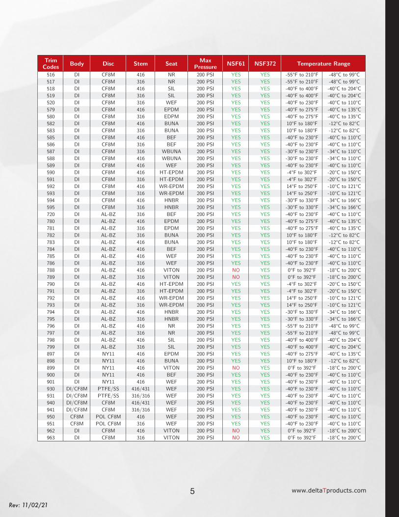
Trim Codes Body Disc Stem Seat NSF61 NSF372 Max
Pressure Temperature Range
261 DI DI-NP 416 NR NO YES 200 PSI -55°F to 210°F -48°C to 99°C262 DI DI-NP 416 EPDM NO YES 200 PSI -40°F to 275°F -40°C to 135°C263 DI DI-NP 416 BUNA NO YES 200 PSI 10°F to 180°F -12°C to 82°C264 DI DI-NP 416 VITON NO YES 200 PSI 0°F to 392°F -18°C to 200°C265 DI DI-NP 416 BEF NO YES 200 PSI -40°F to 230°F -40°C to 110°C266 DI DI-NP 416 WEF NO YES 200 PSI -40°F to 230°F -40°C to 110°C267 DI DI-NP 416 HT-EPDM NO YES 200 PSI -4°F to 302°F -20°C to 150°C268 DI DI-NP 416 WR-EPDM NO YES 200 PSI 14°F to 250°F -10°C to 121°C269 DI DI-NP 416 HNBR NO YES 200 PSI -30°F to 330°F -34°C to 166°C270 DI DI-NP 416 SIL NO YES 200 PSI -40°F to 400°F -40°C to 204°C360 DI/CF8M PTFE/SS 416/431 BEF YES YES 200 PSI -40°F to 230°F -40°C to 110°C361 DI/CF8M PTFE/SS 316/316 BEF YES YES 200 PSI -40°F to 230°F -40°C to 110°C370 DI CF8M 416 BEF YES YES 200 PSI -40°F to 230°F -40°C to 110°C371 DI CF8M 316 BEF YES YES 200 PSI -40°F to 230°F -40°C to 110°C380 DI/CF8M POL CF8M 416/431 BEF YES YES 200 PSI -40°F to 230°F -40°C to 110°C381 DI/CF8M POL CF8M 316/316 BEF YES YES 200 PSI -40°F to 230°F -40°C to 110°C455 DI CF8M 316 PTFE/V YES YES 150 PSI -4°F to 250°F -20°C to 121°C457 DI/CF8M PTFE/SS 316/316 PTFE/V YES YES 150 PSI -4°F to 250°F -20°C to 121°C461 DI/CF8M PTFE/SS 316/316 VITON NO YES 200 PSI 0°F to 392°F -18°C to 200°C462 DI/CF8M PTFE/SS 316/316 PTFE/E YES YES 150 PSI -4°F to 250°F -20°C to 121°C463 DI/CF8M PTFE/SS 416/431 PTFE/E YES YES 150 PSI -4°F to 250°F -20°C to 121°C464 DI/CF8M PTFE/SS 416/431 VITON NO YES 200 PSI 0°F to 392°F -18°C to 200°C465 CF8M POL CF8M 431 BUNA YES YES 200 PSI 10°F to 180°F -12°C to 82°C466 CF8M POL CF8M 316 BUNA YES YES 200 PSI 10°F to 180°F -12°C to 82°C479 CF8M POL CF8M 431 EPDM YES YES 200 PSI -40°F to 275°F -40°C to 135°C480 CF8M POL CF8M 316 EPDM YES YES 200 PSI -40°F to 275°F -40°C to 135°C482 DI/CF8M CF8M 416/431 PTFE/E YES YES 150 PSI -4°F to 250°F -20°C to 121°C482P DI/CF8M POL CF8M 416/431 PTFE/E YES YES 150 PSI -4°F to 250°F -20°C to 121°C483 DI/CF8M CF8M 316/316 PTFE/E YES YES 150 PSI -4°F to 250°F -20°C to 121°C483P DI/CF8M POL CF8M 316/316 PTFE/E YES YES 150 PSI -4°F to 250°F -20°C to 121°C492 CF8M POL CF8M 431 VITON NO YES 200 PSI 0°F to 392°F -18°C to 200°C493 CF8M POL CF8M 316 VITON NO YES 200 PSI 0°F to 392°F -18°C to 200°C
015 = 1.5” (050/051 Only) 050 = Wafer Ductile Iron See Chart Below BST = Bare Stem020 = 2” 051 = Lug Ductile Iron HND = Lever Handle025 = 2.5” 650 = Wafer CF8M GOP = Manual Gear Operator030 = 3” 651 = Lug CF8M040 = 4” 050 = 5” 060 = 6” 080 = 8” 100 = 10” 120 = 12” 140 = 14”160 = 16”180 = 18”200 = 20” 240 = 24”
Size Series Trim Operator
ILP = Lever Handle w/ Infinite Locking Plate
050/051 & 650/651 Butterfly ValvesOrdering Guidelines & Trim Codes
5 www.deltaTproducts.com
Rev: 11/02/21
ILP = Lever Handle w/ Infinite Locking Plate
Trim Codes Body Disc Stem Seat Max
Pressure NSF61 NSF372 Temperature Range
516 DI CF8M 416 NR 200 PSI YES YES -55°F to 210°F -48°C to 99°C517 DI CF8M 316 NR 200 PSI YES YES -55°F to 210°F -48°C to 99°C518 DI CF8M 416 SIL 200 PSI YES YES -40°F to 400°F -40°C to 204°C519 DI CF8M 316 SIL 200 PSI YES YES -40°F to 400°F -40°C to 204°C520 DI CF8M 316 WEF 200 PSI YES YES -40°F to 230°F -40°C to 110°C579 DI CF8M 416 EPDM 200 PSI YES YES -40°F to 275°F -40°C to 135°C580 DI CF8M 316 EDPM 200 PSI YES YES -40°F to 275°F -40°C to 135°C582 DI CF8M 416 BUNA 200 PSI YES YES 10°F to 180°F -12°C to 82°C583 DI CF8M 316 BUNA 200 PSI YES YES 10°F to 180°F -12°C to 82°C585 DI CF8M 416 BEF 200 PSI YES YES -40°F to 230°F -40°C to 110°C586 DI CF8M 316 BEF 200 PSI YES YES -40°F to 230°F -40°C to 110°C587 DI CF8M 316 WBUNA 200 PSI YES YES -30°F to 230°F -34°C to 110°C588 DI CF8M 416 WBUNA 200 PSI YES YES -30°F to 230°F -34°C to 110°C589 DI CF8M 416 WEF 200 PSI YES YES -40°F to 230°F -40°C to 110°C590 DI CF8M 416 HT-EPDM 200 PSI YES YES -4°F to 302°F -20°C to 150°C591 DI CF8M 316 HT-EPDM 200 PSI YES YES -4°F to 302°F -20°C to 150°C592 DI CF8M 416 WR-EPDM 200 PSI YES YES 14°F to 250°F -10°C to 121°C593 DI CF8M 316 WR-EPDM 200 PSI YES YES 14°F to 250°F -10°C to 121°C594 DI CF8M 416 HNBR 200 PSI YES YES -30°F to 330°F -34°C to 166°C595 DI CF8M 316 HNBR 200 PSI YES YES -30°F to 330°F -34°C to 166°C720 DI AL-BZ 316 BEF 200 PSI YES YES -40°F to 230°F -40°C to 110°C780 DI AL-BZ 416 EPDM 200 PSI YES YES -40°F to 275°F -40°C to 135°C781 DI AL-BZ 316 EPDM 200 PSI YES YES -40°F to 275°F -40°C to 135°C782 DI AL-BZ 316 BUNA 200 PSI YES YES 10°F to 180°F -12°C to 82°C783 DI AL-BZ 416 BUNA 200 PSI YES YES 10°F to 180°F -12°C to 82°C784 DI AL-BZ 416 BEF 200 PSI YES YES -40°F to 230°F -40°C to 110°C785 DI AL-BZ 416 WEF 200 PSI YES YES -40°F to 230°F -40°C to 110°C786 DI AL-BZ 316 WEF 200 PSI YES YES -40°F to 230°F -40°C to 110°C788 DI AL-BZ 416 VITON 200 PSI NO YES 0°F to 392°F -18°C to 200°C789 DI AL-BZ 316 VITON 200 PSI NO YES 0°F to 392°F -18°C to 200°C790 DI AL-BZ 416 HT-EPDM 200 PSI YES YES -4°F to 302°F -20°C to 150°C791 DI AL-BZ 316 HT-EPDM 200 PSI YES YES -4°F to 302°F -20°C to 150°C792 DI AL-BZ 416 WR-EPDM 200 PSI YES YES 14°F to 250°F -10°C to 121°C793 DI AL-BZ 316 WR-EPDM 200 PSI YES YES 14°F to 250°F -10°C to 121°C794 DI AL-BZ 416 HNBR 200 PSI YES YES -30°F to 330°F -34°C to 166°C795 DI AL-BZ 316 HNBR 200 PSI YES YES -30°F to 330°F -34°C to 166°C796 DI AL-BZ 416 NR 200 PSI YES YES -55°F to 210°F -48°C to 99°C797 DI AL-BZ 316 NR 200 PSI YES YES -55°F to 210°F -48°C to 99°C798 DI AL-BZ 416 SIL 200 PSI YES YES -40°F to 400°F -40°C to 204°C799 DI AL-BZ 316 SIL 200 PSI YES YES -40°F to 400°F -40°C to 204°C897 DI NY11 416 EPDM 200 PSI YES YES -40°F to 275°F -40°C to 135°C898 DI NY11 416 BUNA 200 PSI YES YES 10°F to 180°F -12°C to 82°C899 DI NY11 416 VITON 200 PSI NO YES 0°F to 392°F -18°C to 200°C900 DI NY11 416 BEF 200 PSI YES YES -40°F to 230°F -40°C to 110°C901 DI NY11 416 WEF 200 PSI YES YES -40°F to 230°F -40°C to 110°C930 DI/CF8M PTFE/SS 416/431 WEF 200 PSI YES YES -40°F to 230°F -40°C to 110°C931 DI/CF8M PTFE/SS 316/316 WEF 200 PSI YES YES -40°F to 230°F -40°C to 110°C940 DI/CF8M CF8M 416/431 WEF 200 PSI YES YES -40°F to 230°F -40°C to 110°C941 DI/CF8M CF8M 316/316 WEF 200 PSI YES YES -40°F to 230°F -40°C to 110°C950 CF8M POL CF8M 416 WEF 200 PSI YES YES -40°F to 230°F -40°C to 110°C951 CF8M POL CF8M 316 WEF 200 PSI YES YES -40°F to 230°F -40°C to 110°C962 DI CF8M 416 VITON 200 PSI NO YES 0°F to 392°F -18°C to 200°C963 DI CF8M 316 VITON 200 PSI NO YES 0°F to 392°F -18°C to 200°C

6Rev: 11/02/21
SEATCartridge-style
seat allows field replacement. NO TAPER PINS
No taper pins on disc ensures trouble-free service and better flow performance.
BACKING RINGRigid backing ring
allows for dead-end service.
STEM BUSHINGSGraphite-reinforced PTFE stem bushings provide for low torque and incredibly long cycle life!
EXTENDED NECKAllows use with insulated pipes.
SECONDARY PROTECTIONSecondary o-ring stem seal protection.
ISO 5211DRIVE STEMEasy direct-mount automation with ISO 5211 standard drive stem and mounting flange.
STEM RETAINER PLATE
Stem retainer plate ensures blowout protection.
UNDERCUT DISC AVAILABLE
for low pressure media.
DUCTILE IRON BODYDurable and economical.
DRY STEM JOURNAL DESIGNCompression energized hub seals & triple stem seals.
Ductile Iron Body - Lug & Wafer Styles
*For sizes larger than 24”, please consult factory
EPOXY POWDER COATINGas standard
050/051 Butterfly ValvesFeatures & Benefits

7 www.deltaTproducts.com
Rev: 11/02/21
EPOXY POWDER COATINGas standard
050/051 Series• 050 Wafer Ductile Iron Body sizes 1.5” - 48”• 051 Lug Ductile Iron Body sizes 1.5” - 48”• Lug-style dead end service capabilities through 12”:
200 PSI uni-directional 100 PSI bi-directional
• Install between Standard ANSI class 125/150 flanges• 050 Wafer also compatible with PN10/PN16 flanges• ISO 5211 square drive shaft for easy automation• Conforms to MSS-SP-67, MSS-SP-25, API–609• Designed for blowout-proof service• High-Cv slim disc & 2-piece stem design 1.5”–12”• Field repairable• Vacuum service capable 1.5”–12” to below 10 microns• Malleable Iron Handles available• Cast Iron Gear Operators available

8Rev: 11/02/21
050/051 Butterfly ValvesDimensions
Ductile Iron Butterfly ValvesSize L Q ØD Lug Taps Wafer Holes H1 H2 H3 S ØF
ISOin mm in mm in mm in mm SAE Thread in mm in mm in mm in mm in mm in mm
1½ DN40 1.3 33 0.8 21 3.88 98.5 1⁄2”- 13 UNC 4 x 0.7 4 x 18 2.5 64 4.9 124 1.18 30 0.354 9 1.969 50 F05
2 DN50 1.7 43 1.1 29 4.75 120.7 4 x 5⁄8 -11 UNC 4 x 0.9 4 x 22 2.6 66 5.1 130 1.18 30 0.354 9 1.969 50 F05
2½ DN65 1.8 46 1.8 45 5.50 139.7 4 x 5⁄8 -11 UNC 4 x 0.7 4 x 18 3.2 81 5.6 142 1.18 30 0.354 9 1.969 50 F05
3 DN75 1.8 46 2.5 62 6.00 152.4 4 x 5⁄8 -11 UNC 4 x 0.7 4 x 18 3.5 89 5.8 147 1.18 30 0.354 9 1.969 50 F05
4 DN100 2.0 52 3.5 89 7.50 190.5 8 x 5⁄8 -11 UNC 4 x 0.7 4 x 18 4.3 109 6.7 170 1.18 30 0.433 11 2.756 70 F07
5 DN125 2.2 56 4.6 116 8.50 215.9 8 x 3⁄4 -10 UNC 4 x 0.9 4 x 22 4.8 122 7.4 188 1.18 30 0.551 14 2.756 70 F07
6 DN150 2.2 56 5.7 145 9.50 241.3 8 x 3⁄4 -10 UNC 4 x 0.9 4 x 22 5.4 137 8.0 203 1.18 30 0.551 14 2.756 70 F07
8 DN200 2.4 60 7.8 197 11.75 298.5 8 x 3⁄4 -10 UNC 4 x 1.0 4 x 26 6.7 170 9.4 239 1.57 40 0.669 17 4.016 102 F10
10 DN250 2.7 68 9.8 248 14.25 362.0 12 x 7⁄8 -9 UNC 4 x 1.0 4 x 26 7.9 201 10.7 272 1.57 40 0.866 22 4.016 102 F10
12 DN300 3.1 78 11.7 298 17.00 431.8 12 x 7⁄8 -9 UNC 4 x 1.0 4 x 26 9.3 236 12.0 305 1.57 40 0.866 22 4.016 102 F10
14 DN350 3.1 78 — — 18.75 476.3 12 x 1 -8 UNC — — 10.3 262 13.0 330 1.57 40 0.866 22 4.016 102 F10
16 DN400 4.0 102 — — 21.25 539.8 16 x 1 -8 UNC — — 11.8 300 14.2 361 2.00 51 1.063 27 5.512 140 F14
18 DN450 4.5 114 — — 22.75 577.9 16 x 1 1⁄8 -7 UNC — — 12.8 325 15.6 396 2.00 51 1.063 27 5.512 140 F14
20 DN500 5.0 127 — — 25.00 635.0 20 x 1 1⁄8 -7 UNC — — 14.2 361 17.3 439 2.52 64 1.063 27 6.496 165 F16
24 DN600 6.1 154 — — 29.50 749.3 20 x 1 1⁄4 -7 UNC — — 16.5 419 19.7 500 2.76 70 1.417 36 6.496 165 F16
Over-Travel on Infinite 2-Position
Lock Option Allows Disc to
Wipe Seat
Valve Sizes ILP Plate
ILP Armin mm
1.5-3" DN40-75 01 01
4" DN100 02 03
5-6" DN125-150 02 04
8"* DN200* 03 05
10-12"* DN250-300* 03 06
Optional Infinite Locking Plates
H1
H2
H3
S ISO 5211MOUNTINGPAD
L
Q
LUG TAPPEDHOLES
WAFERALIGNMENTHOLES
H1
H2
H3
S ISO 5211MOUNTINGPAD
L
Q
LUG TAPPEDHOLES
WAFERALIGNMENTHOLES
ØD
ØF
H1
H2
H3
S ISO 5211MOUNTINGPAD
L
Q
LUG TAPPEDHOLES
WAFERALIGNMENTHOLES
ØD
ØF
Locking Arm (Included w/ Plate)
The standard 10-position throttle plate has grooves that allow the handle to snap in place for repeatability and to prevent unintentional movement of the disc.
For even more control, Infinite Lever Plates (ILP) and arms are available, which allow the valve to be fixed in place with a bolt at any position. It is important to note that the ILP plates and locking arms can be padlocked in the full open and full closed positions only, to prevent tampering or accidental operation.*Recommended operation with a gear
operator or an actuator for sizes 8”–12”

9 www.deltaTproducts.com
Rev: 11/02/21
Handle Part #
Valve Sizes A B C D E F Weight
in mm in mm in mm in mm in mm in mm lbs kgin mm
HND-M01 1.5-3" DN50-75 1.0 26 0.35 9.0 1.3 33 8.9 225 9.4 240 1.1 28 1.1 2.4
HND-M02 4" DN100 1.0 26 0.43 11.0 1.4 35 10.2 260 11.0 280 1.1 28 1.2 2.6
HND-M03 5-6" DN125-150 1.0 26 0.55 14.0 1.4 35 10.2 260 11.0 280 1.1 28 1.3 2.9
HND-M04 8"* DN200* 1.2 30 0.67 17.0 1.9 49 14.0 355 15.2 385 1.3 32 2.6 5.7
HND-M05 10-12"* DN250-300* 1.2 30 0.87 22.0 1.9 49 14.0 355 15.2 385 1.3 32 2.6 5.7
Malleable Iron Handles (w/ Standard Notch Plate)
A
H
B
C
M
Y
CM
MY
CY
CMY
K
051 4in BFV_GO-01-ISO.PDF 1 7/19/12 4:13 PM
*Recommended operation with a gear operator or an actuator for sizes 8”–12”
A
H
B
C
M
Y
CM
MY
CY
CMY
K
051 4in BFV_GO-01-ISO.PDF 1 7/19/12 4:13 PM
Valve Sizes Gear Operator
A B ØH Weight Max Torque Rim Pullin mm in mm in mm in mm lbs kg in-lbs Nm lbf N
1.5–4 DN50–100 GO-01-ISO 1.7 43 3.2 81 6 152 2.8 1.3 1330 150 27 1205–6 DN125–150 GO-02-ISO 2.5 64 3.6 91 6 152 5.6 2.5 2200 250 33 1478-10 DN200-250 GO-03-ISO 2.4 61 4.7 119 10 254 11.5 5.2 4425 500 40 178
12–14 DN300–350 GO-04A-ISO 2.6 66 6.5 165 12 305 22.2 10.1 8850 1000 67 29816–18 DN400–450 GO-05B-ISO 3.5 89 7.9 201 16 406 40.8 18.5 15900 1800 61 271
20 DN500 GO-06B-ISO 5.0 127 10.1 257 16 406 78.1 35.4 30090 3400 91 40524 DN600 GO-07-ISO 6.1 155 12.4 315 16 406 101 45.8 39825 4500 91 405
Cast Iron Gear Operators
050/051 Butterfly ValvesGear and Handle Options

10Rev: 11/02/21
050/051 Butterfly Valves (1.5”-12”)Exploded View
7
5
4
1
8
3
6
11
9
2
10
9 10
9
9
ALUMINUM TAG DETAIL
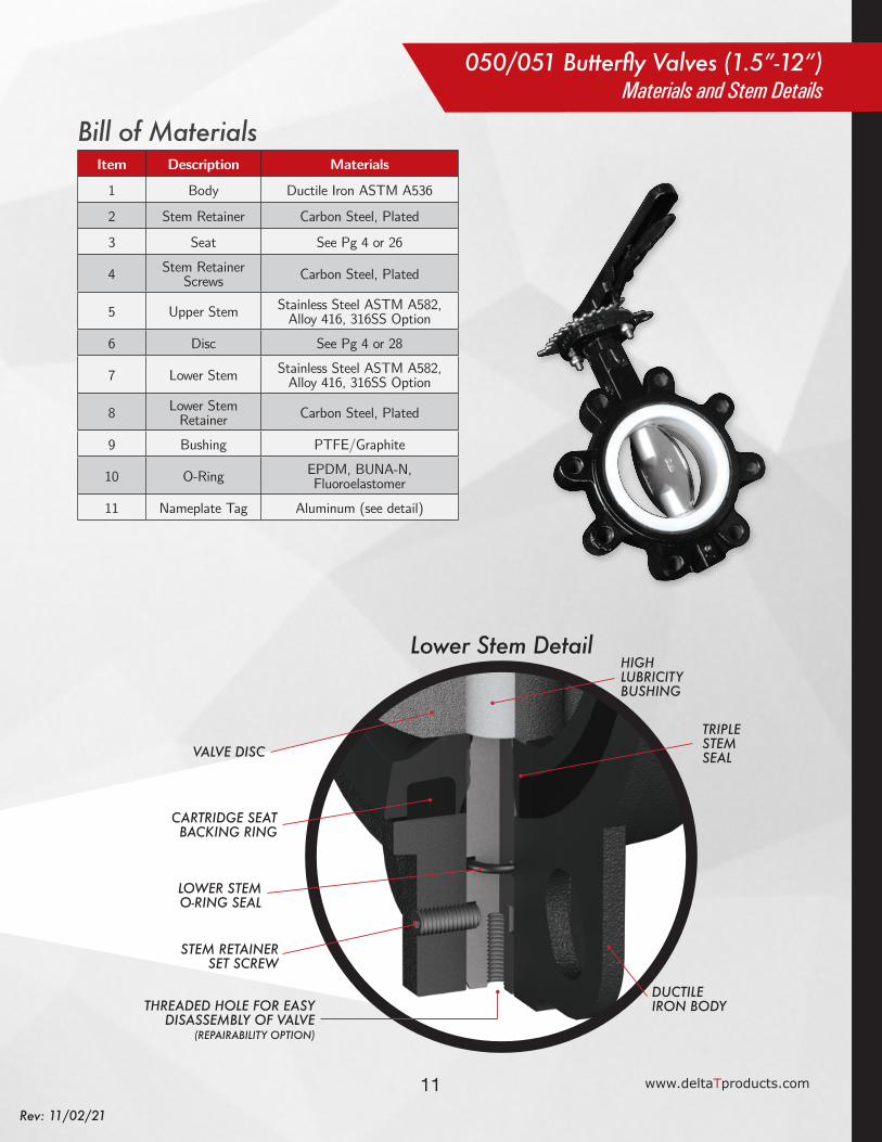
11 www.deltaTproducts.com
Rev: 11/02/21
Lower Stem Detail
Item Description Materials
1 Body Ductile Iron ASTM A536
2 Stem Retainer Carbon Steel, Plated
3 Seat See Pg 4 or 26
4 Stem Retainer Screws Carbon Steel, Plated
5 Upper Stem Stainless Steel ASTM A582, Alloy 416, 316SS Option
6 Disc See Pg 4 or 28
7 Lower Stem Stainless Steel ASTM A582, Alloy 416, 316SS Option
8 Lower Stem Retainer Carbon Steel, Plated
9 Bushing PTFE/Graphite
10 O-Ring EPDM, BUNA-N, Fluoroelastomer
11 Nameplate Tag Aluminum (see detail)
Bill of Materials
HIGH LUBRICITYBUSHING
TRIPLE STEM SEAL
STEM RETAINERSET SCREW
VALVE DISC
CARTRIDGE SEATBACKING RING
LOWER STEMO-RING SEAL
THREADED HOLE FOR EASY DISASSEMBLY OF VALVE
(REPAIRABILITY OPTION)
DUCTILE IRON BODY
050/051 Butterfly Valves (1.5”-12”)Materials and Stem Details

12Rev: 11/02/21
050/051 Butterfly Valves (14”-24”)Exploded View
4
2
5
9
10
9
9
97
8a
8b
10
6
3
1
11
ALUMINUM TAG DETAIL

13 www.deltaTproducts.com
Rev: 11/02/21
050/051 Butterfly Valves (14”-24”)Materials and Stem Details
Lower Stem Detail
Item Description Materials
1 Body Ductile Iron ASTM A536
2 Stem Retainer Carbon Steel, Plated
3 Seat See Pg 4 or 26
4 Stem Retainer Screws Carbon Steel, Plated
5 Upper Stem Stainless Steel ASTM A582, Alloy 416 or 410, 316SS Option
6 Disc See Pg 4 or 28
7 Lower Stem Stainless Steel ASTM A582, Alloy 416 or 410, 316SS Option
8a Lower Stem Retainer Ductile Iron ASTM A536
8bLower Stem
Retainer Bolts and Washers
Carbon Steel, Plated
9 Bushing PTFE/Graphite
10 O-Ring EPDM, BUNA-N, Fluoroelastomer
11 Nameplate Tag Aluminum (see detail)
Bill of Materials
HIGH LUBRICITYBUSHING
LOWER STEMRETAINER CAP
VALVE DISC
DUCTILE IRON BODY
LOWER STEM
COMPRESSION MOLDED CARTRIDGE
STYLE SEAT
TRIPLE STEM SEAL
14Rev: 11/02/21
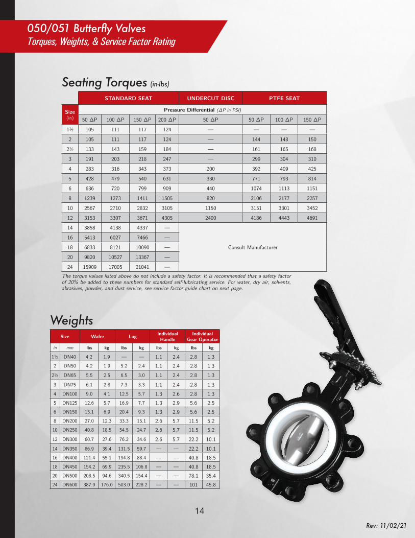
050/051 Butterfly ValvesTorques, Weights, & Service Factor Rating
Size Wafer Lug Individual Handle
Individual Gear Operator
in mm lbs kg lbs kg lbs kg lbs kg
1½ DN40 4.2 1.9 — — 1.1 2.4 2.8 1.32 DN50 4.2 1.9 5.2 2.4 1.1 2.4 2.8 1.3
2½ DN65 5.5 2.5 6.5 3.0 1.1 2.4 2.8 1.33 DN75 6.1 2.8 7.3 3.3 1.1 2.4 2.8 1.34 DN100 9.0 4.1 12.5 5.7 1.3 2.6 2.8 1.35 DN125 12.6 5.7 16.9 7.7 1.3 2.9 5.6 2.56 DN150 15.1 6.9 20.4 9.3 1.3 2.9 5.6 2.58 DN200 27.0 12.3 33.3 15.1 2.6 5.7 11.5 5.210 DN250 40.8 18.5 54.5 24.7 2.6 5.7 11.5 5.212 DN300 60.7 27.6 76.2 34.6 2.6 5.7 22.2 10.114 DN350 86.9 39.4 131.5 59.7 — — 22.2 10.116 DN400 121.4 55.1 194.8 88.4 — — 40.8 18.518 DN450 154.2 69.9 235.5 106.8 — — 40.8 18.520 DN500 208.5 94.6 340.5 154.4 — — 78.1 35.424 DN600 387.9 176.0 503.0 228.2 — — 101 45.8
Weights
The torque values listed above do not include a safety factor. It is recommended that a safety factor of 20% be added to these numbers for standard self-lubricating service. For water, dry air, solvents, abrasives, powder, and dust service, see service factor guide chart on next page.
STANDARD SEAT UNDERCUT DISC PTFE SEAT
Size (in)
Pressure Differential (∆P in PSI)
50 ∆P 100 ∆P 150 ∆P 200 ∆P 50 ∆P 50 ∆P 100 ∆P 150 ∆P
1½ 105 111 117 124 — — — —
2 105 111 117 124 — 144 148 150
2½ 133 143 159 184 — 161 165 168
3 191 203 218 247 — 299 304 310
4 283 316 343 373 200 392 409 425
5 428 479 540 631 330 771 793 814
6 636 720 799 909 440 1074 1113 1151
8 1239 1273 1411 1505 820 2106 2177 2257
10 2567 2710 2832 3105 1150 3151 3301 3452
12 3153 3307 3671 4305 2400 4186 4443 4691
14 3858 4138 4337 —
Consult Manufacturer
16 5413 6027 7466 —
18 6833 8121 10090 —
20 9820 10527 13367 —
24 15909 17005 21041 —
Seating Torques (in-lbs)
15 www.deltaTproducts.com
Rev: 11/02/21
Service Condition Service Type Media Type Safety Factor Multiplier
1 Ideal Lubricating Oil 20% 1.20
2 Normal Water 30% 1.30
3 Severe Dry Air, Solvents 50% 1.50
4 Extreme Abrasives 100% 2.00
Service Factor Rating
This service factor chart is a suggested guide only. Actual service conditions will vary due to dynamic flow conditions and may require adjustments to the applied safety factor.
Size (in)
Disc Position
90° 80° 70° 60° 50° 40° 30° 20° 10°
1½ 99 76 59 41 32 16 7 1.8 0.1
2 132 120 86 58 42 22 11 2 0.1
2½ 256 202 142 98 65 37 20 4 0.2
3 505 392 198 125 86 38 21 8 0.3
4 936 702 401 232 140 77 35 14 0.4
5 1109 922 625 392 232 132 62 29 0.9
6 2531 2009 1105 611 372 203 96 42 2.1
8 4812 3555 1901 1211 726 401 191 65 3.2
10 7498 6183 3740 2065 1232 695 321 151 3.9
12 9928 8805 5905 3178 1909 1065 495 234 5
14 12915 10854 7220 4560 2771 1554 712 338 5.8
16 16626 14961 9909 6289 3780 2133 980 460 8
18 23705 19743 13178 8325 5029 2822 1301 613 10
20 27915 25396 16928 10698 6468 3623 1678 790 12
24 43212 39206 26128 16550 9807 5567 2521 860 21
Cv Values Valve Sizing Coefficients (US-GPM/∆P)
The valve sizing coefficient is referred to as "Cv" and is the rate of water flow in gallons per minute (GPM) through a given opening at a pressure drop (∆P) of 1 PSI at standard room temperature. The recommended angle of opening for valve sizing is between 50° and 70° open.
Pressure Rating050/051 SERIES
Size 1.5”–12” 14”–48” 2"–12" (PTFE)
Bidirectional Shutoff 200 PSI 150 PSI 150 PSI
050/051 Butterfly ValvesCV Values & Testing Specs
16Rev: 11/02/21
SEATCartridge-style
seat allows field replacement.
NO TAPER PINSNo taper pins on disc ensures trouble-free service and better flow performance.
BACKING RINGRigid backing ring allows
for dead-end service.
STEM BUSHINGSGraphite-reinforced PTFE stem bushings provide for low torque and incredibly long cycle life!EXTENDED NECK
Allows use with insulated pipes.
SECONDARYPROTECTIONSecondary o-ring stem seal protection.
ISO 5211 DRIVE STEMEasy direct-mount automation with ISO 5211 standard drive stem and mounting flange.STEM
RETAINER RINGBlowout-proof
stem design
Stainless Steel Body - Lug & Wafer Styles
*For sizes larger than 24”, please consult factory
STAINLESSSTEEL BODYTough andcorrosion-resistantconstruction.
650/651 Butterfly ValvesFeatures & Benefits
DRY STEM JOURNAL DESIGNCompression energized hub seals & triple stem seals.

17 www.deltaTproducts.com
Rev: 11/02/21
650/651 Series• 650 Wafer Stainless Steel Body sizes 2” - 24”• 651 Lug Stainless Steel Body sizes 2” - 24”• Lug-style dead end service capabilities through 12”
100 PSI bi-directional• Install between Standard ANSI class 125/150 flanges• ISO 5211 square drive shaft for easy automation• Conforms to MSS-SP-67, MSS-SP-25, API–609• Designed for blowout-proof service• High-Cv slim disc & 2-piece stem design 2”–12”• Field repairable• Vacuum service capable 2” thru 12” to 10 microns• 304 SS Handles available• Cast Iron Gear Operators available
18Rev: 11/02/21
Size L Q ØD Lug Taps Wafer Holes H1 H2 H3 S ØFISO
in mm in mm in mm in mm SAE Thread in mm in mm in mm in mm in mm in mm
2 DN50 1.7 43 1.1 29 4.75 120.7 4 x 5⁄8 -11 UNC 4 x 0.9 4 x 22 2.6 66 5.1 130 1.18 30 0.354 9 1.969 50 F05
2½ DN65 1.8 46 1.8 45 5.50 139.7 4 x 5⁄8 -11 UNC 4 x 0.7 4 x 18 3.2 81 5.6 142 1.18 30 0.354 9 1.969 50 F05
3 DN75 1.8 46 2.5 62 6.00 152.4 4 x 5⁄8 -11 UNC 4 x 0.7 4 x 18 3.5 89 5.8 147 1.18 30 0.433 11 1.969 50 F05
4 DN100 2.0 52 3.5 89 7.50 190.5 8 x 5⁄8 -11 UNC 4 x 0.7 4 x 18 4.3 109 6.7 170 1.18 30 0.433 11 2.756 70 F07
5 DN125 2.2 56 4.6 116 8.50 215.9 8 x 3⁄4 -10 UNC 4 x 0.9 4 x 22 4.8 122 7.4 188 1.18 30 0.551 14 2.756 70 F07
6 DN150 2.2 56 5.7 145 9.50 241.3 8 x 3⁄4 -10 UNC 4 x 0.9 4 x 22 5.4 137 8.0 203 1.18 30 0.551 14 2.756 70 F07
8 DN200 2.4 60 7.8 197 11.75 298.5 8 x 3⁄4 -10 UNC 4 x 1.0 4 x 26 6.7 170 9.4 239 1.57 40 0.669 17 4.016 102 F10
10 DN250 2.7 68 9.8 248 14.25 362.0 12 x 7⁄8 -9 UNC 4 x 1.0 4 x 26 7.9 201 10.7 272 1.57 40 0.866 22 4.016 102 F10
12 DN300 3.1 78 11.7 298 17.00 431.8 12 x 7⁄8 -9 UNC 4 x 1.0 4 x 26 9.3 236 12.0 305 1.57 40 0.866 22 4.016 102 F10
14 DN350 3.1 78 — — 18.75 476.3 12 x 1 -8 UNC — — 10.3 262 13.0 330 1.57 40 0.866 22 4.016 102 F10
16 DN400 4.0 102 — — 21.25 539.8 16 x 1 -8 UNC — — 11.8 300 14.2 361 2.00 51 1.063 27 5.512 140 F14
18 DN450 4.5 114 — — 22.75 577.9 16 x 1 1⁄8 -7 UNC — — 12.8 325 15.6 396 2.00 51 1.063 27 5.512 140 F14
20 DN500 5.0 127 — — 25.00 635.0 20 x 1 1⁄8 -7 UNC — — 14.2 361 17.3 439 2.52 64 1.063 27 6.496 165 F16
24 DN600 6.1 154 — — 29.50 749.3 20 x 1 1⁄4 -7 UNC — — 16.5 419 19.7 500 2.76 70 1.417 36 6.496 165 F16
650/651 Butterfly ValvesDimensions
Stainless Steel Butterfly Valves
Optional Infinite
Lever Plate
Locking Arm (Included w/ Plate)
Valve Sizes ILP Plate
ILP Armin mm
2-2.5" DN50-65 01 01
3" DN75 01 03
4" DN100 02 03
5-6" DN125-150 02 04
8" DN200* 03 05
10-12" DN250-300* 03 06
Optional Infinite Locking Plates
H2
H1
H3
L
Q
S ISO 5211MOUNTINGPAD
LUGTAPPEDHOLES
WAFERALIGNMENTHOLES
ØD
ØF
The standard 10-position throttle plate has grooves that allow the handle to snap in place for repeatability and to prevent unintentional movement of the disc.
For even more control, Infinite Lever Plates (ILP) and arms are available, which allow the valve to be fixed in place with a bolt at any position. It is important to note that the ILP plates and locking arms can be padlocked in the full open and full closed positions only, to prevent tampering or accidental operation.
H2
H1
H3
L
Q
S ISO 5211MOUNTINGPAD
LUGTAPPEDHOLES
WAFERALIGNMENTHOLES
ØD
ØF
H2
H1
H3
L
Q
S ISO 5211MOUNTINGPAD
LUGTAPPEDHOLES
WAFERALIGNMENTHOLES
ØD
ØF
*Recommended operation with a gear operator or an actuator for sizes 8”–12”

19 www.deltaTproducts.com
Rev: 11/02/21
Size L Q ØD Lug Taps Wafer Holes H1 H2 H3 S ØFISO
in mm in mm in mm in mm SAE Thread in mm in mm in mm in mm in mm in mm
2 DN50 1.7 43 1.1 29 4.75 120.7 4 x 5⁄8 -11 UNC 4 x 0.9 4 x 22 2.6 66 5.1 130 1.18 30 0.354 9 1.969 50 F05
2½ DN65 1.8 46 1.8 45 5.50 139.7 4 x 5⁄8 -11 UNC 4 x 0.7 4 x 18 3.2 81 5.6 142 1.18 30 0.354 9 1.969 50 F05
3 DN75 1.8 46 2.5 62 6.00 152.4 4 x 5⁄8 -11 UNC 4 x 0.7 4 x 18 3.5 89 5.8 147 1.18 30 0.433 11 1.969 50 F05
4 DN100 2.0 52 3.5 89 7.50 190.5 8 x 5⁄8 -11 UNC 4 x 0.7 4 x 18 4.3 109 6.7 170 1.18 30 0.433 11 2.756 70 F07
5 DN125 2.2 56 4.6 116 8.50 215.9 8 x 3⁄4 -10 UNC 4 x 0.9 4 x 22 4.8 122 7.4 188 1.18 30 0.551 14 2.756 70 F07
6 DN150 2.2 56 5.7 145 9.50 241.3 8 x 3⁄4 -10 UNC 4 x 0.9 4 x 22 5.4 137 8.0 203 1.18 30 0.551 14 2.756 70 F07
8 DN200 2.4 60 7.8 197 11.75 298.5 8 x 3⁄4 -10 UNC 4 x 1.0 4 x 26 6.7 170 9.4 239 1.57 40 0.669 17 4.016 102 F10
10 DN250 2.7 68 9.8 248 14.25 362.0 12 x 7⁄8 -9 UNC 4 x 1.0 4 x 26 7.9 201 10.7 272 1.57 40 0.866 22 4.016 102 F10
12 DN300 3.1 78 11.7 298 17.00 431.8 12 x 7⁄8 -9 UNC 4 x 1.0 4 x 26 9.3 236 12.0 305 1.57 40 0.866 22 4.016 102 F10
14 DN350 3.1 78 — — 18.75 476.3 12 x 1 -8 UNC — — 10.3 262 13.0 330 1.57 40 0.866 22 4.016 102 F10
16 DN400 4.0 102 — — 21.25 539.8 16 x 1 -8 UNC — — 11.8 300 14.2 361 2.00 51 1.063 27 5.512 140 F14
18 DN450 4.5 114 — — 22.75 577.9 16 x 1 1⁄8 -7 UNC — — 12.8 325 15.6 396 2.00 51 1.063 27 5.512 140 F14
20 DN500 5.0 127 — — 25.00 635.0 20 x 1 1⁄8 -7 UNC — — 14.2 361 17.3 439 2.52 64 1.063 27 6.496 165 F16
24 DN600 6.1 154 — — 29.50 749.3 20 x 1 1⁄4 -7 UNC — — 16.5 419 19.7 500 2.76 70 1.417 36 6.496 165 F16
A
H
B
C
M
Y
CM
MY
CY
CMY
K
051 4in BFV_GO-01-ISO.PDF 1 7/19/12 4:13 PM
A
H
B
C
M
Y
CM
MY
CY
CMY
K
051 4in BFV_GO-01-ISO.PDF 1 7/19/12 4:13 PM
E
A
B F
D
C
DO NOT SCALE DRAWING4in BFV Handle
SHEET 1 OF 1
BW
UNLESS OTHERWISE SPECIFIED:
SCALE: 1:2 WEIGHT:
DWG. NO.
ASIZE
TITLE:
NAME DATE
REVISIONS:
CHECKED
DRAWN
FINISH
MATERIAL
INTERPRET GEOMETRICTOLERANCING PER:
DIMENSIONS ARE IN INCHESTOLERANCES:FRACTIONAL 1/32ANGULAR: MACH BEND TWO PLACE DECIMAL 0.015THREE PLACE DECIMAL .005
PROPRIETARY AND CONFIDENTIALTHE INFORMATION CONTAINED IN THISDRAWING IS THE SOLE PROPERTY OFMAX-AIR TECHNOLOGY, INC. ANY REPRODUCTION IN PART OR AS A WHOLEWITHOUT THE WRITTEN PERMISSION OFMAX-AIR TECHNOLOGY, INC. IS PROHIBITED.
5 4 3 2 1
751 Hoff RoadO'Fallon, MO 63366
Phone: 888-842-9998Fax: 636-272-4937
max-airtechnology.com
REV
COMMENTS:
C
M
Y
CM
MY
CY
CMY
K
4in BFV Handle.PDF 1 7/30/12 11:44 AM
Handle Part #
Valve Sizes A B C D E F Weight
in mm in mm in mm in mm in mm in mm lbs kgin mm
HND-S01 2-2.5" DN50-75 1.1 28 0.35 9.0 1.3 34 10.2 260 11.2 285 1.1 27 1.0 2.2
HND-S02 3-4" DN100 1.1 28 0.43 11.0 1.3 34 10.2 260 11.2 285 1.1 27 1.0 2.2
HND-S03 5-6" DN125-150 1.1 28 0.55 14.0 1.3 34 10.2 260 11.2 285 1.1 27 1.0 2.2
HND-S04 8"* DN200* 1.2 30 0.67 17.0 1.9 49 14.7 373 15.7 400 1.3 33 2.5 5.5
HND-S05 10-12"* DN250-300* 1.2 30 0.87 22.0 1.9 49 14.7 373 15.7 400 1.3 33 2.5 5.5
Stainless Steel Handles (w/ Standard Notch Plate)
*Recommended operation with a gear operator or an actuator for sizes 8”–12”
Cast Iron Gear OperatorsValve Sizes Gear
OperatorA B ØH Weight Output Torque Rim Pull
in mm in mm in mm in mm lbs kg in-lbs Nm lbf N2–4 DN50–100 GO-01-ISO 1.7 43 3.2 81 6 152 2.8 1.3 1330 150 27 1205–6 DN125–150 GO-02-ISO 2.5 64 3.6 91 6 152 5.6 2.5 2200 250 33 1478-10 DN200-250 GO-03-ISO 2.4 61 4.7 119 10 254 11.5 5.2 4425 500 40 178
12–14 DN300–350 GO-04A-ISO 2.6 66 6.5 165 12 305 22.2 10.1 8850 1000 67 29816–18 DN400–450 GO-05B-ISO 3.5 89 7.9 201 16 406 40.8 18.5 15900 1800 61 271
20 DN500 GO-06B-ISO 5.0 127 10.1 257 16 406 78.1 35.4 30090 3400 91 40524 DN600 GO-07-ISO 6.1 155 12.4 315 16 406 101 45.8 39825 4500 91 405
650/651 Butterfly ValvesGear and Handle Options

20Rev: 11/02/21
650/651 Butterfly Valves (2”-12”)Exploded View
2
7
7
8
9
4
7
1
11
10
3
5
6
8
STAINLESS STEEL TAG DETAIL

21 www.deltaTproducts.com
Rev: 11/02/21
Item Description Materials
1 Body ASTM A351 grade CF8M
2 Seat See Pg 4 or 26
3 Upper Stem ASTM A276 431, 316SS Option
4 Disc See Pg 4 or 28
5 Lower Stem ASTM A276 431, 316SS Option
6 Lower Stem Retainer 304 SS
7 Stem Bushing PTFE lined fiberglass
8 O-ring Fluoroelastomer
9 Nameplate Tag Stainless Steel (see detail)
10 Split Washer 1Cr13
11 Snap Ring 304 SS
Bill of Materials
650/651 Butterfly Valves (2”-12”)Materials and Stem Detail
Lower Stem Detail
HIGH LUBRICITYBUSHING
CF8M BODY
COMPRESSION MOLDED CARTRIDGE STYLE SEAT
LOWER STEM0-RING SEAL
THREADED HOLETO FACILITATE EASY
DISASSEMBLY OF VALVE
STAINLESS STEELRETAINER PLUG SEAL(REPAIRABILITY OPTION)
VALVE DISC
TRIPLE STEM SEAL

22Rev: 11/02/21
2
3
4
5
6
7
7
8
8
9
10
650/651 Butterfly Valves (14”-24”)Exploded View
STAINLESS STEELTAG DETAIL
1
11
23 www.deltaTproducts.com
Rev: 11/02/21
650/651 Butterfly Valves (14”-24”)Materials and Stem Detail
Lower Stem Detail
Item Description Materials
1 Body ASTM A351 grade CF8M
2 Seat See Pg 4 or 26
3 Upper Stem ASTM A276 431, 316SS Option
4 Disc See Pg 4 or 28
5 Lower Stem ASTM A276 431, 316SS Option
6 Lower Stem Retainer 304 SS
7 Stem Bushing PTFE lined fiberglass
8 O-ring Fluoroelastomer
9 Split Washer 1Cr13
10 Snap Ring 304 SS
11 Nameplate Tag Stainless Steel (see detail)
Bill of Materials
HIGH LUBRICITYBUSHING
LOWER STEM0-RING SEAL
COMPRESSIONMOLDED CARTRIDGE
STYLE SEAT
CF8M BODY
STAINLESS STEELRETAINER PLUG SEAL(REPAIRABILITY OPTION)
VALVE DISC
TRIPLE STEM SEAL

24Rev: 11/02/21
The torque values listed above do not include a safety factor. It is recommended that a safety factor of 20% be added to these numbers for standard self-lubricating service. For water, dry air, solvents, abrasives, powder, and dust service, see service factor guide chart on next page.
STANDARD SEAT UNDERCUT DISC PTFE SEAT
Size (in)
Pressure Differential (∆P in PSI)
50 ∆P 100 ∆P 150 ∆P 200 ∆P 50 ∆P 50 ∆P 100 ∆P 150 ∆P
2 105 111 117 124 — 144 148 150
2½ 133 143 159 184 — 161 165 168
3 191 203 218 247 — 299 304 310
4 283 316 343 373 200 392 409 425
5 428 479 540 631 330 771 793 814
6 636 720 799 909 440 1074 1113 1151
8 1239 1273 1411 1505 820 2106 2177 2257
10 2567 2710 2832 3105 1150 3151 3301 3452
12 3153 3307 3671 4305 2400 4186 4443 4691
14 3858 4138 4337 —
Consult Manufacturer
16 5413 6027 7466 —
18 6833 8121 10090 —
20 9820 10527 13367 —
24 15909 17005 21041 —
Seating Torques (in-lbs)
650/651 Butterfly ValvesTorque & Service Factor Ratings
Size Wafer Weight
Lug Weight
Individual Handle
Individual Gear Operator
in mm lbs kg lbs kg lbs kg lbs kg
2 DN50 6.0 2.7 10.4 4.7 1.0 2.4 2.8 1.32½ DN65 7.5 3.4 11.2 5.1 1.0 2.4 2.8 1.33 DN75 8.4 3.8 19.0 8.6 .9 2.4 2.8 1.34 DN100 11.5 5.2 21.6 9.8 .9 2.6 2.8 1.35 DN125 16.1 7.3 28.4 12.9 .9 2.9 5.6 2.56 DN150 18.3 8.3 31.3 14.2 .9 2.9 5.6 2.58 DN200 30.4 13.8 45.6 20.7 2.5 5.7 11.5 5.210 DN250 44.1 20.0 69.4 31.5 2.5 5.7 11.5 5.212 DN300 75.4 34.2 115.3 52.3 2.5 5.7 22.2 10.114 DN350 99.0 44.9 170.4 77.3 — — 22.2 10.116 DN400 121.3 55.0 213.2 96.7 — — 40.8 18.518 DN450 202.8 92.0 262.8 119.2 — — 40.8 18.520 DN500 — — — — — — 78.1 35.424 DN600 — — — — — — 101 45.8
Weights

25 www.deltaTproducts.com
Rev: 11/02/21
Service Condition Service Type Media Type Safety Factor Multiplier
1 Ideal Lubricating Oil 20% 1.20
2 Normal Water 30% 1.30
3 Severe Dry Air, Solvents 50% 1.50
4 Extreme Abrasives 100% 2.00
Service Factor Rating
This service factor chart is a suggested guide only. Actual service conditions will vary due to dynamic flow conditions and may require adjustments to the applied safety factor.
Size (in)
Disc Position
90° 80° 70° 60° 50° 40° 30° 20° 10°
2 132 120 86 58 42 22 11 2 0.1
2½ 256 202 142 98 65 37 20 4 0.2
3 505 392 198 125 86 38 21 8 0.3
4 936 702 401 232 140 77 35 14 0.4
5 1109 922 625 392 232 132 62 29 0.9
6 2531 2009 1105 611 372 203 96 42 2.1
8 4812 3555 1901 1211 726 401 191 65 3.2
10 7498 6183 3740 2065 1232 695 321 151 3.9
12 9928 8805 5905 3178 1909 1065 495 234 5
14 12915 10854 7220 4560 2771 1554 712 338 5.8
16 16626 14961 9909 6289 3780 2133 980 460 8
18 23705 19743 13178 8325 5029 2822 1301 613 10
20 27915 25396 16928 10698 6468 3623 1678 790 12
24 43212 39206 26128 16550 9807 5567 2521 860 21
Cv Values Valve Sizing Coefficients (US-GPM/∆P)
The valve sizing coefficient is referred to as "Cv" and is the rate of water flow in gallons per minute (GPM) through a given opening at a pressure drop (∆P) of 1 PSI at standard room temperature. The recommended angle of opening for valve sizing is between 50° and 70° open.
Pressure Rating
650/651 SERIES
Size 2”–12” 14”–48” 2"–12" (PTFE)
Bidirectional Shutoff 200 PSI 150 PSI 150 PSI
650/651 Butterfly ValvesCV Values & Testing Specs

26Rev: 11/02/21
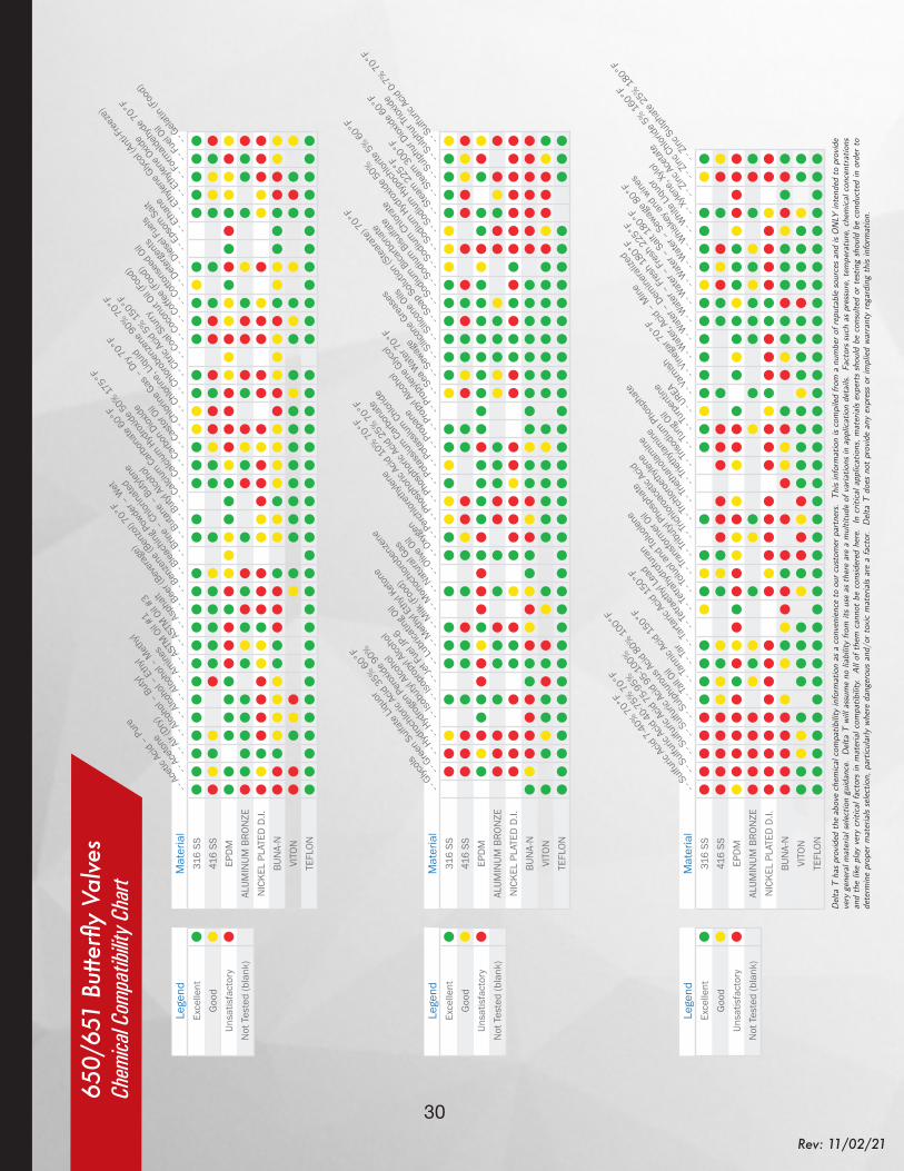
DeltaT 050/051 & 650/651 Butterfly ValvesSeat Material Guide
Seat Material(Backing Material) Code General Application Temperature Range
at Full Rated PressureNot Recommended
For
EPDM(Phenolic) EPDM
H20, Air, Brine, Abrasives, Phosphates, Esters Ketones, Alkali, Food Compounds, Liquids and Solids, Diluite Inorganic Acids, Caustic
Soda
-40°F to 275°F(-40°C to 135°C)
Hydrocarbons, Oils, Fats, Dry Air
White EPDM Food Grade(Phenolic) WEF -40°F to 212°F
(-40°C to 100°C)
Black EPDM Food Grade(Phenolic) BEF -40°F to 230°F
(-40°C to 110°C)
High Temp EPDM(Phenolic) HT-EPDM Standard EPDM + Low
Pressure Saturated Steam-4°F to 302°F
(-20°C to 150°C)
Wear Resistant EPDM(Phenolic) WR-EPDM Standard EPDM + Abrasive
Products14°F to 250°F
(-40°C to 121°C)
BUNA-N (NBR)(Phenolic) BUNA
Hydrocarbons with less than 40% of aromatics, Natural Gas, Air, H20, Sea Water, Brine, Alcohols, Glycols
10°F to 180°F(-12°C to 82°C)
Solvents, Benzene, Xylene
White BUNA Food Grade(Phenolic) WBF -30°F to 230°F
(-30°C to 110°C)
High Temp BUNA (Hydrogenated NBR)
(Phenolic)HT-BUNA Standard BUNA + Low
Pressure Saturated Steam-30°F to 330°F
(-34°C to 165°C)
VITON (FKM)(Aluminum) VITON
Hydrocarbons wth high concentration of aromatics, Mineral and Halogenated
Acids, Phorforic Acid, Alphatic and Aromatic
Ethers
0°F to 300°F(-18°C to 149°C)
Steam, Ketones, Amines, Esters, Alkali
PTFE over EPDM (Phenolic) PTFE/E
Corrosive Products - Solvents
-4°F to 275°F(-20°C to 135°C)
Abrasive products, Fluorine Gases, Alkaline
MetalsPTFE over VITON
(Aluminum) PTFE/V -4°F to 300°F(-20°C to 149°C)
*Material guidelines for reference only. Actual suitability can depend on a combination of temperature, pressure, chemical concentration and other variables.

27 www.deltaTproducts.com
Rev: 11/02/21
Superior Cartridge Seat DesignWhy a DeltaT Cartridge Seat Is the Preferred Choice:
Seat Material(Backing Material) Code General Application Temperature Range
at Full Rated PressureNot Recommended
For
EPDM(Phenolic) EPDM
H20, Air, Brine, Abrasives, Phosphates, Esters Ketones, Alkali, Food Compounds, Liquids and Solids, Diluite Inorganic Acids, Caustic
Soda
-40°F to 275°F(-40°C to 135°C)
Hydrocarbons, Oils, Fats, Dry Air
White EPDM Food Grade(Phenolic) WEF -40°F to 212°F
(-40°C to 100°C)
Black EPDM Food Grade(Phenolic) BEF -40°F to 230°F
(-40°C to 110°C)
High Temp EPDM(Phenolic) HT-EPDM Standard EPDM + Low
Pressure Saturated Steam-4°F to 302°F
(-20°C to 150°C)
Wear Resistant EPDM(Phenolic) WR-EPDM Standard EPDM + Abrasive
Products14°F to 250°F
(-40°C to 121°C)
BUNA-N (NBR)(Phenolic) BUNA
Hydrocarbons with less than 40% of aromatics, Natural Gas, Air, H20, Sea Water, Brine, Alcohols, Glycols
10°F to 180°F(-12°C to 82°C)
Solvents, Benzene, Xylene
White BUNA Food Grade(Phenolic) WBF -30°F to 230°F
(-30°C to 110°C)
High Temp BUNA (Hydrogenated NBR)
(Phenolic)HT-BUNA Standard BUNA + Low
Pressure Saturated Steam-30°F to 330°F
(-34°C to 165°C)
VITON (FKM)(Aluminum) VITON
Hydrocarbons wth high concentration of aromatics, Mineral and Halogenated
Acids, Phorforic Acid, Alphatic and Aromatic
Ethers
0°F to 300°F(-18°C to 149°C)
Steam, Ketones, Amines, Esters, Alkali
PTFE over EPDM (Phenolic) PTFE/E
Corrosive Products - Solvents
-4°F to 275°F(-20°C to 135°C)
Abrasive products, Fluorine Gases, Alkaline
MetalsPTFE over VITON
(Aluminum) PTFE/V -4°F to 300°F(-20°C to 149°C)
Seat Material(Backing Material) Code General Application Temperature Range
at Full Rated PressureNot Recommended
For
Natural Rubber(Phenolic) NR Abrasive Products -55°F to 210°F
(-48°C to 99°C) ???
Silicone (Phenolic) SIL Beverages, Food -40°F to 400°F
(-40°C to 204°C)Hydrocarbons,
Solvents, Steam
Chlorosulfonated Synthetic Rubber
(Phenolic)CSM
Oxidizing Acids, Chromic Acid, Hydrofluoric Acid,
Sulphur Based Acids, Sodium Hypoclonte, ozone
0°F to 275°F(-18°C to 135°C)
Steam, Ketones, Hot Air, Nitric Acid
Neoprene(Phenolic) NP Oils, Dilute Mineral Acids,
Alkali, Fats20°F to 200°F(-7°C to 93°C)
Ketones, Concentrated Acids, Solvents for
Paint
Booted seat bulging around disc contact
points
Cartridge seat with rigid phenolic
backing ring
Molded seat permanently bonded
to valve body
Feature Cartridge Seat
Molded Seat
Booted Seat
Replaceable YES NO YESConsistent Torque YES NO NO
Ideal for Vacuum Service YES YES NODead End Service Capable YES YES NO
Deformation Resistant YES YES NOFlange Type Independent YES YES NO
Booted - Poor
Molded - OK
Cartridge - Best

28Rev: 11/02/21
DI-NP Nickel Plated Ductile IronDuctile iron disc for strength, coated with Nickel Plating for corrosion resistance and increased abrasion resistance.
Recommend Applications: Air, Kerosene, Oils, Ketones, Hydrocarbons, Solvents, Detergents, Salts, Concentrated Organic Acids
Not Recommended For: Inorganic Acids, Diluted Organic Acids
NY11Nylon 11 Coated Ductile IronDuctile iron disc for strength, coated with Nylon 11 for corro-sion resistance and excellent abrasion resistance.
Recommended Applications: Inorganic Salts, Alkalis, Most Solvents, Most Organic Acids, Hydrocarbons, Oils, Kerosene, Ketones, Esters, Detergents, Sea Water, Abrasives
Not Recommended For: Inorganic Acids, Phenols, Chlorinated Solvents
AL-BZAluminum BronzeStrength similar to carbon steel, but with an aluminum oxide layer on the surface for excellent corrosion resistance.
Recommended Applications: Sea Water, Brine, Detergents, Gasoline, Alcohols, Esters, Ketones, Potable Water
Not Recommended For: Acids
CF8M316 Stainless SteelStainless steel disc is inherently strong for industrial use and cor-rosion resistant for a wide range of chemical and environmental applications.
Recommended Applications: Acetic Acids, Air, Automotive Oils & Fuels, Beer, Freon, Gaso-line, Ketones, Oils, Oxygen, Steam, Sea Water, Potable Water
Not Recommended For: Acids
PTFEPTFE Coated 316 Stainless Steel
Recommended Applications: Acids, Alcohols, Solvents, Oils, Potable Water
Not Recommended For: Fluorine
PolishedPolished 316 Stainless SteelAll the benefits of stainless steel strength and corrosion resistance, plus a highly polished surface for sanitary applications.
Recommended Applications: Sanitary Applications, Potable Water
Not Recommended For: Acids
DeltaT 050/051 & 650/651 Butterfly ValvesDisc Material Guide
*Material guidelines for reference only. Actual suitability can depend on a combination of temperature, pressure, chemical concentration and other variables.

29 www.deltaTproducts.com
Rev: 11/02/21
50 PSI Rated Bubble Tight Shut offLower torque
Full RatedBubble TightShut Off 150/200 PSI
Under CutFull Cut
Disc OptionsFull Cut vs. Under Cut & Disc Options
VS
Why Full Cut?Full cut discs provide bubble tight shut off at 150/200 PSI for a wide variety of applications, such as liquid or gas media.
Why Under Cut?Under cut discs require less torque to operate but are only rated to 50 PSI bubble tight shutoff. common ap-plications are solids dispensing or conveying, or any low pressure process.
Valve & Disc Treatment Options
Oxygen CleanWhy oxygen clean treatment?Oxygen cleaning is conducted on valves to prevent the potentially violent oxidation (fire or explosion) of contaminants (most often hydrocarbons) on the surfaces exposed to oxygen within a process. The valves are subsequently sealed within polyethylene bags to prevent recontamination prior to installation.What’s treated?Total Valve
PassivationWhy passivation treatment?Passivation is a process by which the inherent corrosion resistance of stainless steel is maximized through a two step process of cleaning and subsequent immersion in an acid bath thereby creating a uniform oxidation layer that optimizes the corrosion resistance.What’s treated?Disc only
Silicone FreeWhy silicone free treatment?Silicone Free cleaning is conducted on valves in order to prevent silicone contamination within processes (such as automotive painting) that are sensitive to silicone. The valves are subsequently sealed within polyethylene bags to prevent recontamination prior to installation.What’s treated?Total Valve
Slim Disc DesignWhat is the advantage of the Slim Disc design?Delta T’s slim disc design minimizes the disc profile to maximize flow. This is especially important for smaller butterfly valves where the disc takes up proportunionally more of the flow path. Slim disc design is standard up to 12” sizes.
Standard Disc Design14” and up
Slim Disc High Cv DesignUp to 12”
SEAT SEAT
DISC DISC
*Material guidelines for reference only. Actual suitability can depend on a combination of temperature, pressure, chemical concentration and other variables.
30Rev: 11/02/21
Mat
eria
l31
6 SS
416
SSEP
DM
ALUM
INUM
BRO
NZE
NIC
KEL
PLAT
ED D
.I.BU
NA-
NVI
TON
TEFL
ON
- - Ac
etic
Acid
– Pu
re
- - Ac
etone
- - Air
(Dry)
- - Alc
ohol
– But
yl
- - Alc
ohol
– Et
hyl
- - Alc
ohol
– Met
hyl
- - Am
ines
- - AS
TM O
il #1
- - AS
TM O
il #3
- - As
phalt
- - Bee
r (Bev
erag
e)
- - Ben
zene
(Ben
zol) 7
0°F
- - Blea
ching
Powde
r – W
et
- - Brin
e – C
hlorin
ated
- - But
ane –
But
ylene
- - But
yl Alc
ohol
- - Ca
lcium
Car
bona
te 60
°F
- - Ca
lcium
Hyd
roxide
50%
175°
F
- - Ca
rbon
Diox
ide
- - Ca
stor O
il
- - Ch
lorine
Gas
– D
ry 70
°F
- - Ch
lorine
, Liqu
id
- - Ch
lorob
enze
ne 9
0% 7
0°F
- - Cit
ric Ac
id 5%
150
°F
- - Co
al Slu
rry
- - Co
conu
t Oil (
Food
)
- - Co
ffee (
Food
)
- - Co
ttons
eed O
il
- - Dete
rgen
ts
- - Dies
el Fu
els
- - Ep
som Sa
lt
- - Et
hane
- - Et
hylen
e Glyc
ol (A
nti-F
reez
e)
- - Et
hylen
e Oxid
e
- - Fo
rmald
ehyd
e 70°
F
- - Fu
el Oil
- - Gela
tin (F
ood)
Lege
ndEx
celle
ntG
ood
Unsa
tisfa
ctor
yN
ot T
este
d (b
lank
)
Lege
ndEx
celle
ntG
ood
Unsa
tisfa
ctor
yN
ot T
este
d (b
lank
)
Lege
ndEx
celle
ntG
ood
Unsa
tisfa
ctor
yN
ot T
este
d (b
lank
)
Mat
eria
l31
6 SS
416
SSEP
DM
ALUM
INUM
BRO
NZE
NIC
KEL
PLAT
ED D
.I.BU
NA-
NVI
TON
TEFL
ON
- - Glyc
ols
- - Gre
en Su
lfate
Liquo
r
- - Hyd
roch
loric
Acid
35% 6
0°F
- - Hyd
roge
n Per
oxide
90%
- - Iso
butyl
Alco
hol
- - Iso
prop
yl Alc
ohol
- - Je
t Fue
l JP-6
- - Lu
brica
ting O
il
- - Met
hyl E
thyl
Ketone
- - Milk
(Foo
d)
- - Mon
ochlo
robe
nzen
e
- - Nat
ural
Gas
- - Oliv
e Oil
- - Oxy
gen
- - Pe
rchlor
ethy
lene
- - Ph
osph
oric
Acid
10% 7
0°F
- - Ph
osph
oric
Acid
25% 7
0°F
- - Po
tass
ium C
arbo
nate
- - Po
tass
ium C
hlorid
e
- - Pr
opan
e
- - Pr
opyl
Alcoh
ol
- - Pr
opyle
ne G
lycol
- - Se
a Wat
er 7
0°F
- - Se
wage
- - Sil
icone
Gre
ases
- - Sil
icone
Oils
- - So
ap So
lution
(Stea
rate)
70°
F
- - So
dium B
icarb
onat
e
- - So
dium B
isulfa
te
- - So
dium C
hlora
te
- - So
dium H
ydrox
ide 5
0%
- - So
dium H
ypoc
hlorit
e 5% 6
0°F
- - St
eam 2
25°F
- - St
eam 3
00°F
- - Su
lphur
Diox
ide 6
0°F
- - Su
lphur
Triox
ide
- - Su
lfuric
Acid
0-7%
70°
F
Mat
eria
l31
6 SS
416
SSEP
DM
ALUM
INUM
BRO
NZE
NIC
KEL
PLAT
ED D
.I.BU
NA-
NVI
TON
TEFL
ON
- - Su
lfuric
Acid
7-40
% 70°
F
- - Su
lfuric
Acid
40-7
5% 7
0°F
- - Su
lfuric
Acid
75-9
5%
- - Su
lfuric
Acid
95-10
0%
- - Su
lphur
ous A
cid 8
0% 10
0°F
- - Ta
ll Oil
- - Ta
nnic
Acid
150°
F
- - Ta
r - - Ta
rtaric
Acid
150°
F
- - Te
traet
hyl L
ead
- - Te
trahy
drof
uran
- - To
luol a
nd To
luolen
e
- - Tra
nsfor
mer O
il
- - Tri
butyl
Phos
phat
e
- - Tri
chlor
oace
tic Ac
id
- - Trc
hloro
ethy
lene
- - Tri
etha
nolam
ine
- - Tri
ethy
lamine
- - Tri
sodiu
m Phos
phat
e
- - Tu
ng O
il
- - Tu
rpen
tine
- - UREA
- - Va
rnish
- - Vin
egar
70°
F
- - Wat
er, Ac
id –
Mine
- - Wat
er –
Dem
inera
lized
- - Wat
er –
Fres
h 180
°F
- - Wat
er –
Fres
h 225
°F
- - Wat
er –
Salt 1
80°F
- - Wat
er –
Sewag
e 80°
F
- - Whis
key a
nd w
ines
- - Whit
e Liqu
or
- - Xy
lene,
Xylol
- - Zin
c Ace
tate
- - Zin
c Chlo
ride 5
% 160°
F
- - Zin
c Sulp
hate
25% 1
80°F
650/
651
Butte
rfly
Valv
esCh
emica
l Com
patib
ility C
hart
Delt
a T
has p
rovi
ded
the
abov
e ch
emica
l com
patib
ility
info
rmat
ion
as a
con
veni
ence
to o
ur c
usto
mer
par
tner
s. T
his i
nfor
mat
ion
is co
mpi
led fr
om a
num
ber o
f rep
utab
le so
urce
s and
is O
NLY
inte
nded
to p
rovi
de
very
gen
eral
mat
eria
l sele
ctio
n gu
idan
ce.
Delt
a T
will
assu
me
no li
abili
ty fr
om it
s use
as t
here
are
a m
ultit
ude
of v
aria
tions
in a
pplic
atio
n de
tails
. Fa
ctor
s suc
h as
pre
ssur
e, te
mpe
ratu
re, c
hem
ical c
once
ntra
tions
an
d th
e lik
e pl
ay v
ery
criti
cal f
acto
rs in
mat
eria
l com
patib
ility
. Al
l of t
hem
can
not
be c
onsid
ered
her
e. I
n cr
itica
l app
licat
ions
, mat
eria
ls ex
pert
s sh
ould
be
cons
ulte
d or
tes
ting
shou
ld b
e co
nduc
ted
in o
rder
to
dete
rmin
e pr
oper
mat
eria
ls se
lectio
n, p
artic
ular
ly w
here
dan
gero
us a
nd/o
r tox
ic m
ater
ials
are
a fa
ctor
. D
elta
T do
es n
ot p
rovi
de a
ny e
xpre
ss o
r im
plied
war
rant
y re
gard
ing
this
info
rmat
ion.
31 www.deltaTproducts.com
Rev: 11/02/21
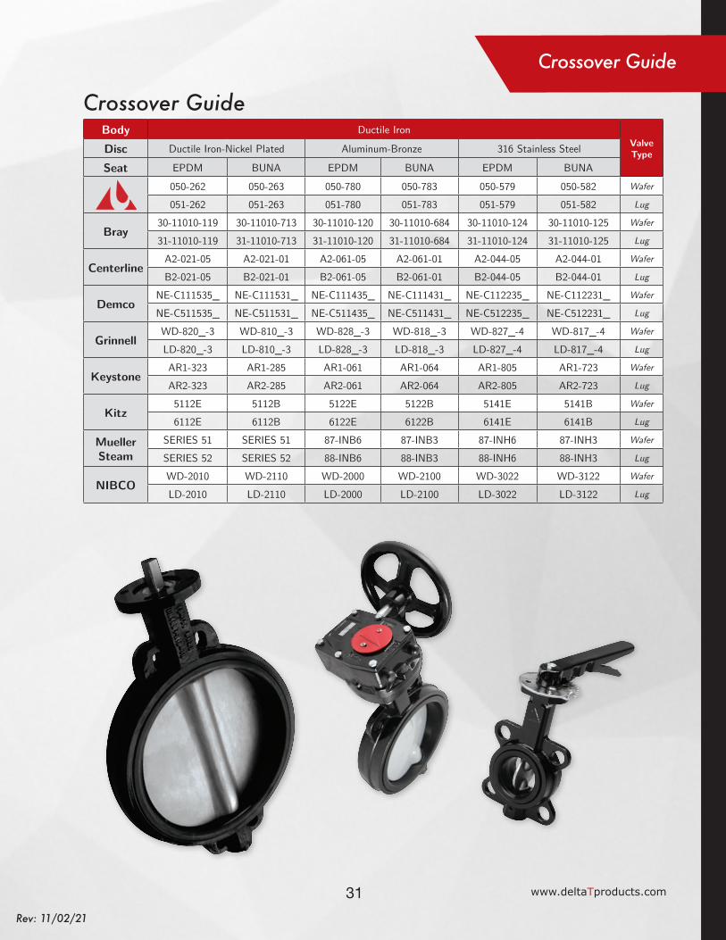
Body Ductile IronValve TypeDisc Ductile Iron-Nickel Plated Aluminum-Bronze 316 Stainless Steel
Seat EPDM BUNA EPDM BUNA EPDM BUNA
050-262 050-263 050-780 050-783 050-579 050-582 Wafer
051-262 051-263 051-780 051-783 051-579 051-582 Lug
Bray30-11010-119 30-11010-713 30-11010-120 30-11010-684 30-11010-124 30-11010-125 Wafer
31-11010-119 31-11010-713 31-11010-120 31-11010-684 31-11010-124 31-11010-125 Lug
CenterlineA2-021-05 A2-021-01 A2-061-05 A2-061-01 A2-044-05 A2-044-01 Wafer
B2-021-05 B2-021-01 B2-061-05 B2-061-01 B2-044-05 B2-044-01 Lug
DemcoNE-C111535_ NE-C111531_ NE-C111435_ NE-C111431_ NE-C112235_ NE-C112231_ Wafer
NE-C511535_ NE-C511531_ NE-C511435_ NE-C511431_ NE-C512235_ NE-C512231_ Lug
GrinnellWD-820_-3 WD-810_-3 WD-828_-3 WD-818_-3 WD-827_-4 WD-817_-4 Wafer
LD-820_-3 LD-810_-3 LD-828_-3 LD-818_-3 LD-827_-4 LD-817_-4 Lug
KeystoneAR1-323 AR1-285 AR1-061 AR1-064 AR1-805 AR1-723 Wafer
AR2-323 AR2-285 AR2-061 AR2-064 AR2-805 AR2-723 Lug
Kitz5112E 5112B 5122E 5122B 5141E 5141B Wafer
6112E 6112B 6122E 6122B 6141E 6141B Lug
Mueller Steam
SERIES 51 SERIES 51 87-INB6 87-INB3 87-INH6 87-INH3 Wafer
SERIES 52 SERIES 52 88-INB6 88-INB3 88-INH6 88-INH3 Lug
NIBCOWD-2010 WD-2110 WD-2000 WD-2100 WD-3022 WD-3122 Wafer
LD-2010 LD-2110 LD-2000 LD-2100 LD-3022 LD-3122 Lug
Crossover Guide
Crossover Guide
Delt
a T
has p
rovi
ded
the
abov
e ch
emica
l com
patib
ility
info
rmat
ion
as a
con
veni
ence
to o
ur c
usto
mer
par
tner
s. T
his i
nfor
mat
ion
is co
mpi
led fr
om a
num
ber o
f rep
utab
le so
urce
s and
is O
NLY
inte
nded
to p
rovi
de
very
gen
eral
mat
eria
l sele
ctio
n gu
idan
ce.
Delt
a T
will
assu
me
no li
abili
ty fr
om it
s use
as t
here
are
a m
ultit
ude
of v
aria
tions
in a
pplic
atio
n de
tails
. Fa
ctor
s suc
h as
pre
ssur
e, te
mpe
ratu
re, c
hem
ical c
once
ntra
tions
an
d th
e lik
e pl
ay v
ery
criti
cal f
acto
rs in
mat
eria
l com
patib
ility
. Al
l of t
hem
can
not
be c
onsid
ered
her
e. I
n cr
itica
l app
licat
ions
, mat
eria
ls ex
pert
s sh
ould
be
cons
ulte
d or
tes
ting
shou
ld b
e co
nduc
ted
in o
rder
to
dete
rmin
e pr
oper
mat
eria
ls se
lectio
n, p
artic
ular
ly w
here
dan
gero
us a
nd/o
r tox
ic m
ater
ials
are
a fa
ctor
. D
elta
T do
es n
ot p
rovi
de a
ny e
xpre
ss o
r im
plied
war
rant
y re
gard
ing
this
info
rmat
ion.

32Rev: 11/02/21
ILP Shown
Padlocked in
the Fully
Closed Position
ILP Shown
Bolted in an
Intermediate
Position
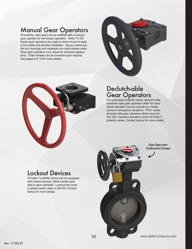
DeltaT AccessoriesHandles, Gear Operators, Lockout Devices
Handles & Throttle PlatesDelta T butterfly valves can be readily equipped with lever handles for easy manual operation, which come standard with a 10 position notch plate for quick open/close and throttling. Ductile iron valves are available with malleable iron handles and standard plated carbon steel notch plate. Stainless steel valves are available with 304 SS handles and matching 304 SS notch plates. Lever handles and notch plates are available up through 12” sizes. See pages 9 & 19 for more handle details.
Infinite Locking Plates & ArmsFor more adjustable throttling and lockout capability on lever handle operated valves, Delta T “ILP” series infinite locking plates are designed to directly replace the standard notch plates. ILP kits come with a 304 SS base plate and arm to allow throttling posi-tions at any angle and lockout at full open or closed. Delta T infinite locking plates can be used on either ductile iron or stainless steel butterfly valves up through 12” sizes. See pages 8 & 18 for more details.
33 www.deltaTproducts.com
Rev: 11/02/21
Gear OperatorPadlocked Closed
Manual Gear OperatorsAll butterfly valve sizes can be outfitted with a manual gear operator for low-torque operation. Delta T’s GO Series gear operators are made to direct mount to keep a low profile and simplify installation. Epoxy coated duc-tile iron housings and malleable iron hand wheels make these gear operators very robust for industrial applica-tions. Chain wheels can be furnished upon request.See pages 9 & 19 for more details.
Declutch-able Gear OperatorsFor automated butterfly valves, declutch-able sandwich style gear operators allow for hand wheel operated manual override for mainte-nance or emergency situations. PV01 series declutch-able gear operators direct mount to ISO 5211 standard actuators and to all Delta T butterfly valves. Contact factory for more details.
Lockout DevicesAll Delta T butterfly valves can be equipped with lockout devices, either handle oper-ated or gear operated. Lockout kits come in plated carbon steel or 304 SS. Contact factory for more details.
34Rev: 11/02/21
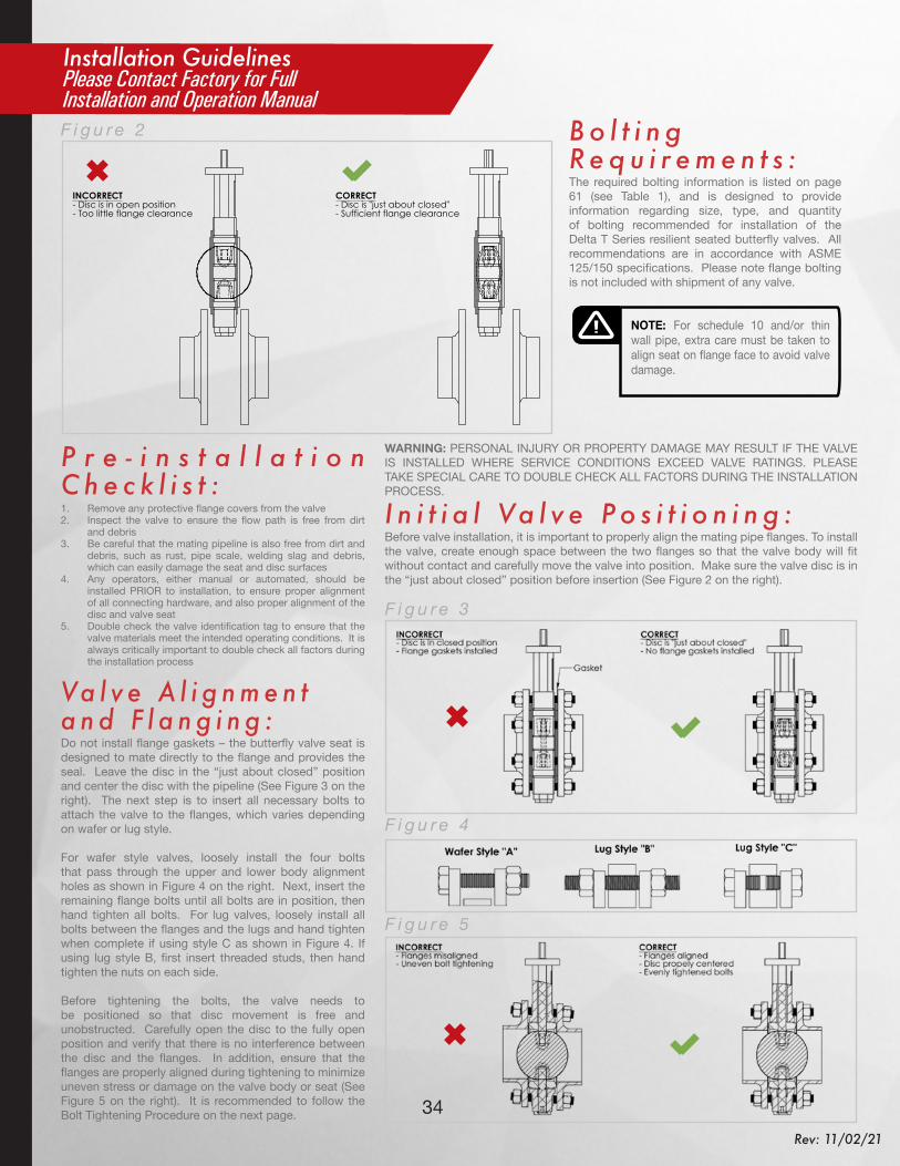
Installation GuidelinesPlease Contact Factory for Full Installation and Operation Manual
INCORRECT- Disc is in open position- Too little flange clearance
CORRECT- Disc is "just about closed"- Sufficient flange clearance
0
BFV Initial Installation Diagram
DT-13-DELTAT-003WEIGHT:
8.5x11"
SHEET 1 OF 1SCALE:1:4
DWG NO.
TITLE:
REVISION DO NOT SCALE DRAWING
MATERIAL:
DATESIGNATURENAME
DEBUR AND BREAK SHARP EDGES
FINISH:UNLESS OTHERWISE SPECIFIED:DIMENSIONS ARE IN MILLIMETERSSURFACE FINISH:TOLERANCES: LINEAR: ANGULAR:
Q.A
MFG
APPV'D
CHK'D
DRAWN
DESCRIPTIONDATEREV
F i g u r e 2
NOTE: For schedule 10 and/or thin wall pipe, extra care must be taken to align seat on flange face to avoid valve damage.
B o l t i n g R e q u i r e m e n t s : The required bolting information is listed on page 61 (see Table 1), and is designed to provide information regarding size, type, and quantity of bolting recommended for installation of the Delta T Series resilient seated butterfly valves. All recommendations are in accordance with ASME 125/150 specifications. Please note flange bolting is not included with shipment of any valve.
P r e - i n s t a l l a t i o n C h e c k l i s t : 1. Remove any protective flange covers from the valve2. Inspect the valve to ensure the flow path is free from dirt
and debris3. Be careful that the mating pipeline is also free from dirt and
debris, such as rust, pipe scale, welding slag and debris, which can easily damage the seat and disc surfaces
4. Any operators, either manual or automated, should be installed PRIOR to installation, to ensure proper alignment of all connecting hardware, and also proper alignment of the disc and valve seat
5. Double check the valve identification tag to ensure that the valve materials meet the intended operating conditions. It is always critically important to double check all factors during the installation process
Va l v e A l i g n m e n t a n d F l a n g i n g : Do not install flange gaskets – the butterfly valve seat is designed to mate directly to the flange and provides the seal. Leave the disc in the “just about closed” position and center the disc with the pipeline (See Figure 3 on the right). The next step is to insert all necessary bolts to attach the valve to the flanges, which varies depending on wafer or lug style. For wafer style valves, loosely install the four bolts that pass through the upper and lower body alignment holes as shown in Figure 4 on the right. Next, insert the remaining flange bolts until all bolts are in position, then hand tighten all bolts. For lug valves, loosely install all bolts between the flanges and the lugs and hand tighten when complete if using style C as shown in Figure 4. If using lug style B, first insert threaded studs, then hand tighten the nuts on each side. Before tightening the bolts, the valve needs to be positioned so that disc movement is free and unobstructed. Carefully open the disc to the fully open position and verify that there is no interference between the disc and the flanges. In addition, ensure that the flanges are properly aligned during tightening to minimize uneven stress or damage on the valve body or seat (See Figure 5 on the right). It is recommended to follow the Bolt Tightening Procedure on the next page.
F i g u r e 3
F i g u r e 4
F i g u r e 5
WARNING: PERSONAL INJURY OR PROPERTY DAMAGE MAY RESULT IF THE VALVE IS INSTALLED WHERE SERVICE CONDITIONS EXCEED VALVE RATINGS. PLEASE TAKE SPECIAL CARE TO DOUBLE CHECK ALL FACTORS DURING THE INSTALLATION PROCESS.
I n i t i a l Va l v e P o s i t i o n i n g : Before valve installation, it is important to properly align the mating pipe flanges. To install the valve, create enough space between the two flanges so that the valve body will fit without contact and carefully move the valve into position. Make sure the valve disc is in the “just about closed” position before insertion (See Figure 2 on the right).

35 www.deltaTproducts.com
Rev: 11/02/21
B o l t T i g h t e n i n g S e q u e n c e : For lugged style valves (particularly important for PTFE seated valves), it is essential to tighten the flange bolting uniformly on both sides of the valve to assure that the cartridge seat is not forced out of position. Improper tightening can result in leakage through the stem seals. The proper tightening procedure is as follows (See Figure 6 on the right):
1. If using a long stud and nuts as in style “B”, after positioning the valve between the mating flanges, install the nuts in all positions to hand tight or just until they contact the flange face only. If using bolts as in style “C”, tighten the bolts on both sides of the valve until they are hand tight or just contacting the flange face.
2. The nuts or bolts immediately on either side of the upper stem (position 1 & 2) should be tightened first. Start with position 1 and tighten bolts/nuts in ½ turn increments, alternating between the front and back flanges.
3. Once that position is tight, proceed to tighten the bolt/nut pair opposite from the pair that was just tightened and tighten in the same fashion (position 2).
4. Follow the same sequence as in steps 2 and 3 above on the opposite end of the valve near the lower stem (positions 3 & 4).
5. Tighten the remaining bolts (if any) in a star pattern around the valve and then re-check all bolts/nuts for tightness in a star pattern for all bolts/nuts (position 5, 6, 7, 8, etc). Make sure to alternate sides and tighten in 1/2 turn increments.
C a u t i o n : Note that resilient seated butterfly valves are designed around the ID for schedule 40 pipe as it is the most common wall thickness utilized. As such, there are some cautions that users must be aware of when utilizing thinner wall or heavier wall pipe. These can also apply to the use of special face rings and van stone flanges.
1. When installed with thin wall pipe, schedule 10 or lighter (common in SS pipe applications), the alignment of the valve against the flange face becomes critical. As the pipe has a larger ID than the valve, there is less gasketing surface available so the valve MUST be very accurately centered with the flanges on both sides. If it is not, leakage at the flange faces or thought the stem bores could occur. Face rings can make this situation worse as they frequently have a radius or bevel at the face to pipe transition.
2. When installed with heavy wall pipe, most common with plastic piping systems, the ID of the pipe should be checked against the “Q” dimension of the butterfly valve. If the Q dimension is larger than the pipe ID or very close, beveled adapters may be required for the valve to be able to fully open.
F i g u r e 6
F l a n g e B o l t i n g R e q u i r e m e n t s :
NOTE: These torque values are a general recommendation ONLY for minimum tightening torques. Many factors affect tightening requirements including bolt grade, pipe alignment, flange material and others. Field engineering personnel must make final torque value decisions. Call factory for flange bolting requirements up to 48” size.
Valve Size
Diameter Machine & Stud #
Cap Screw #
Bolt Length A
Stud Length B
Cap Screw Length C
Thread Size
Recommended Torque in-lbs
1.5" 0.500 4 8 3.25 3.75 1.25 1/2"-13UNC 25-302" 0.625 4 8 4.00 5.00 1.25 5/8"-11UNC 30-35
2.5" 0.625 4 8 4.25 5.25 1.50 5/8"-11UNC 30-353" 0.625 4 8 4.50 5.25 1.50 5/8"-11UNC 35-404" 0.625 8 16 5.00 6.00 1.75 5/8"-11UNC 35-405" 0.750 8 16 5.50 6.50 1.75 3/4"-10-UNC 35-506" 0.750 8 16 5.50 6.75 2.00 3/4"-10UNC 35-658" 0.750 8 16 6.00 7.00 2.25 3/4"-10UNC 45-80
10" 0.875 12 24 6.75 8.00 2.25 7/8"-9UNC 55-10012" 0.875 12 24 7.00 8.25 2.50 7/8"-9UNC 65-12014" 1.000 12 24 7.75 9.00 2.75 1"-8UNC 75-13016" 1.000 16 32 8.00 9.00 3.25 1"-8UNC 75-14018" 1.125 16 32 8.75 10.00 3.50 1-1/8"-7UNC 85-17020" 1.125 20 40 9.50 10.75 3.75 1-1/8"-7UNC 85-18024" 1.250 20 40 10.25 12.50 4.50 1-1/4"-7UNC 100-220

DELTA PRODUCTST
DELTA PRODUCTSTT H E B R A N D
B Y W H I C HA L L O T H E R S A R E
MEASURED
11/02/21Rev. November 2, 2021
*QR Code for Website
www.deltaTproducts.com