deformation measurements with...
TRANSCRIPT

TRANSPORTATION RESEARCH RECORD 1169
Deformation Measurements with Inclinometers
GORDON E. GREEN AND P. ERIK MIKKELSEN
Inclinometers have steadily gained widespread use for measuring deformations In landslides, natural slope creep, temporary excavations, earth and rock embankments, slurry walls, shafts, tunnels, lateral pile movements, and settlements beneath tanks, fills, and foundations. Inclinometer data can be used to determine displacement magnitude and rate and the location of the zone of displacement, as well as the absolute p!)Sition of the inclinometer casing In the ground. High-precision Inclinometers today utlllze servo-accelerometer sensors In a unlaxlal or biaxial configuration, mounted Inside a waterproof wheel caiJriage. The most common Is the traversing borehole type, where the wheels are oriented and guided by specially made grooved casing. Fixed-In-place inclinometers employ the same guide casing but are used infrequently due to high cost. Inclinometer monitoring Is one of the most labor- and data-Intensive geotechnlcal measuring activities. In addition to straightforward data reduction, many errors have to be Identified and dealt with before results can be presented and correctly Interpreted. In the authors' experience, many Inclinometer monitoring programs have failed to yield good results because errors were not recognized. In this paper, guidance Is given to the reader regarding Inclinometer system design, Installation, monitoring, data processing, and sources of errors and their resolution. Accuracy of the Inclinometer Is highly dependent on the equipment selected, the method by which it Is installed in the ground, monitoring techniques, correct scrutiny of the data, and ability to correct instrument errors. A servoaccelerometer-type system Is capable of a precision of ±0.05 to 0.25 in. over 100 ft when the casing Is vertical or horizontal. The best results are achieved when cooperation and understanding between engineers, clients, and contractors provide continuity in the total monitoring process.
The measurement of ground movements is an essential part of many civil and mining engineering operations. Monitoring subsurface movements with inclinometers can be considered a direct extension of normal surface survey techniques. fuclinometer systems are used extensively to monitor the displacement magnitude, rate of displacement (i.e., accelerating or decelerating), and location of the movement zone. fu many situations, where, how much, and whether or not the movement is increasing or decreasing are key issues. fuclinometer systems can be used to monitor displacements in landslides, natural slope creep, temporary excavations, earth and rockfill dams, slurry walls, shafts, tunnels, lateral pile movements, and settlement under tanks, fills, and foundations. fuclinometers are also
G. E. Green, 9835 4 lst Avenue, N.E., Seattle, Wash. 98115. P. E. Mikkelsen, Slope Indicator Company, 3668 Albion Place North, Seattle, Wash. 98103.
used to determine the absolute position of boreholes prior to installing other inst:rllments, for example, geophones or tieback tendons. They may also be used indirectly to measure moments and stresses in structures and can give good results with flexible steel structures where the deflection is large and the section modulus is known. Their value in composite concrete structures where the moment of inertia is uncertain is more limited.
The inclinometer commonly used today developed from a device built in 1952 by S. D. Wilson at Harvard University. It first became available commercially in the late 1950s from the Slope Indicator Company. Such an inclinometer consists of a probe, containing a gravity-actuated transducer, which is fitted with wheels and lowered on an electrical cable down a grooved casing to control orientation (1, 2) (see Figure 1). The cable is connected to a readout unit, and data can be recorded manually or automatically. The inclination of the casing with respect to gravity is measured at incremental depths, and the entire casing profile is obtained by numerical integration. Sets of readings taken periodically enable both the magnitude and rate of lateral casing movement to be calculated. The casing is normally set in vertical drillholes or attached to a structure in a vertical position to measure horizontal movements (Figure 2). It can also be set horizontally to measure heave or settlement (Figures 3-5) but will not measure movements in a horizontal plane. Movements of casings inclined up to 45 degrees may also be monitored but with considerably less accuracy (7).
FIGURE I Principles of operation of probe Inclinometer.

2
~ .,----..,""",.,,.,_- ,_ o[ • • • ~ SETTLEMENT t: 1 • • .. • •
w IJ)
DEFLECTION (cm)
0
FIFTH AVE •
CLAY
TRANSPORTATION RESEARCH RECORD 1169
.. . .. .... . . 9/82 l SAND l GRAVEL
TILL - · -12/82
MEASURED ------ 3/83 SANO/SIL Ti CLAY
I I
I I
---8/83
FEM DEFLECTIONS AT END OF EXCAVATION
10 15 20
: / . ib''\\'CIJ\l.,.-3/83 EXCAVATION COMPLETED
,8/83 El. 13
EL. 7 (TIP OF SOLDIER PILE)
SCALE IN METERS El , -3 BOTTOM OF INCLINOMETER
FIGURE 2 Shoring wall movements on the 34-m-deep Columbia Center excavation In Seattle, Washington (3).
have recently become available appear to be more promising (9).
Inclinometers may also be combined with probe extensometcr systems that measure exhmsion or compression along the axis of the inclinometer casing, a mechanical probe that locates casing joints. or an induction coil or m!!gnet/re~-<l switch se:nsor. When these devices are installed on vertical casings, they permit settlement or heave monitoring so that subsurface threedimensional movements are monitored (JO).
30 JO Inclinometer monitoring is one of the most labor-intensive
geotechnical measurement activities. It generates large volumes of numerical data that must be correctly recorded, processed, scrutinized for errors, ploued, and interpreted. Experience indicates that many inclinometer measurement projects fai l to achieve their intended aim because of a lack of appreciation of the many factors, both human and instrument, that need to be correctly implemented. Thus, in many cases, thick files of unplotted data are generated, or depth/ displacement profiles wander mysteriously back and forth across a graph, or large movements are believed to be occurring when there may actually be lillle or none. More information concerning inclinometer systems and their use may be found elsewhere (10-16).
40
60
FIGURE 3 Vertical and borlzontal monitoring of an oil tank foundation during water test loading (4).
Fixed-in-place inclinometers are available. They consist of a series of sensors with guide wheels, each containing a uniaxial or biaxial gravity-operated transducer that generates electrical signals. The sensors are joined by articulated rods and are suspended permanently in vertical grooved casing. Continuous or remote monitoring or both, by direct wire link, radio, or telephone modem, permit real-time data to be obtained in critical situations, in contrast to the manually read probe inclinometer system.
Other types of drillhole survey tools are also available. The oil well and geophysical logging industry use a variety of photographic, gyroscopic, and gravity-based electronic sensors that operate in Wllined vertical drillholes and do not require casing with oriented grooves. At1cmpts have been made to develop versions of these tools (8) that are suitable for civil and mining use in boreholes 50- to 300-ft deep as an alternative to the probe inclinometer used inside grooved casings, but these efforts have been relatively unsuccessful to date due to cost, convenience, size, and accuracy. The rate gyro-based tools that
INCLINOMETER EQUIPMENT
The accuracy and reliability of the measured position or displacement profile is dependent on the quality of the casing, probe, cable, readout, and accessories selected. A poorly engineered probe, stretchy cable, faulty readout, or inferior casing will resltll in poor quality data at best, and an unhappy user.
Inclinometer casings may be plastic, aluminum alloy, or steel, with rigid or telescopic couplings (see Figure 6). Plastic casings may be ABS, PVC, or fiberglass and the grooves may be Conned by broaching, extrusion, or moulding. ABS is fiex.ible and easily cemented, PVC less o. The casing groove ~piral should be less than 1 degree per 10 fl, and for plastics, a broached tube appears to be betcer than an extruded casing. Even so, hot sun and improper storage can warp and twist an initially str:tight casing. Casing diameter rartge from 1.9 LO 3.8

Green and Milli/sen 3
. .. ~ " "
= ~ ·:::: : == -----------;----~----:----=----;----;----~----~----~-- --3----~~~~~~~~~~~~~~~~~==========· I
~ !
FIGURE 4 Horlwntal inclinometer monitoring of a rockfill dam (5).
in., and the larger sizes are preferable where movements are large, thin shear 7.0nes are present, and drilling costs permit. Rigid couplings are available, with self-aligning features that include flush couplings for use where borehole space is Light Connections may be made with rive1s, plastic cement, or a self aligning Wcstbay coupling that incorporates an 0 -ring and nylon shear key that is very convenient. The aluminum alloy
casing is extruded with grooves, and a close-fitting, similar second extrusion is employed for rigid or telescopic joints. Joints are riveted and must be sealed with mastic and tape. This aluminum alloy casing is subject Lo corrosion in alkaline environmenls. Some records have shown that in the presence of steel, electrolysis has caused a total loss in a few monlhs. Baked-on epoxy paint offers the best protection, but even so,
30 FT . .,.£---.,-.--., SETILEMENT, IN. 1.0 2.0
20 FT.
EXTENSOMETER EX-1
EXTENSOMETER EX-4
10 FT.
20 FT
·., ... 'II
9 IN
..... 1.0 30 FT. -'----J HEAVE, IN.
360+90 360+70
INCLINOMETER 80-3
1 1-271 -· I
\ 0
'2 .0
9 IN. LEGEND
DATE, LOCATION. ANO DIRECTION OF TBM MOVEMENT
(JI
g ITi ;:
~ ~
NOTE: TBM WAS WITHDRAWN FROM HEADING BETWEEN 2·4 ANO 2-17 AND THE HEADING FILLED WITH GROUT. THE HEADING WAS READVANCED ON 3-20·83.
360+50 360+30 STATION, FT.
FIGURE S Vertical rock deformations In a tunnel In response to tunnel boring machine advance (6).

4
FIGURE 6 Digitilt inclinometer, manual readout, Inclinometer casing, and couplings.
corrosion can occur, and ground conditions need to be carefully assessed before an aluminum alloy casing is selected. In benign environments, some users prefer aluminum casings over plastic (17). In some instances, seamless welded square steel tube can be used where great strength is required (e.g., auached to driven steel piles) or where the user wishes to attach strain gauges to the casing for axial strain measurements (e.g., in concrete piles). Otherwise, the steel tube is subject to corrosion and to loss of precision of probe location within the casing. Extruded steel tubing is usually twisted excessively and should not be used.
The gravity-actuated sensor may employ a rotary potentiometer, bonded resistance strain gauges, vibrating wire strain gauges, an electrolytic level, or a servo-accelerometer. The now discontinued Slope Indicator 200B employed a rotary potentiometer with a relay-operated contact to reduce friction. This sensor was stable and reliable but bulky. The Soil Instruments Mark II inclinometer, also discontinued, incorporated a strain gauge steel leaf spring with an oil-damped pendulum. The sensor was reasonably stable and reliable but subject to damage if it was not immobilized in transit. European manufacturers have incorporated the vibrating wire strain gauge on dual-axis pendulum devices, which are reliable but cumbersome. The electrolytic level has only been used in horizontal inclinometers because (a) it is currently too large to mount laterally in a vertical probe, (b) it has a more limited angular range, and (c) it is relatively sensitive to temperature. The servo-accelerometer is the sensor most widely used today. A product of the space program, the accelerometer can also be used in a static mode to
TRANSPORTATION RESEARCH RECORD 1169
measure angle. A very small, damped pendulous mass suspended by an elastic flexure is electrically nulled, with the voltage proportional to angle. The servo-accelerometer is accurate, reliable, reasonably robust, and compact, and two of them can be mounted in a slender biaxial probe for vertical casings.
The probe body (Figure 6) should be waterproof and preferably of stainless steel, wiih a well-engineered wheel carriage that has little or no side play in the wheels, axle, and swing arm assemblies. Preferably, the wheels should have double ball bearings and a wheel rim profile that is compatible with the casing groove geometry. Self-centering wheels are better than the earlier fixed-spring wheel assemblies. Wheel geometry and carriage design control the precision with which the probe can be relocated each time in the casing. This factor is particularly important with the currently used biaxial probes, which utilize only one pair of grooves and rely on the sides of the grooves for B-direction location. A sealed electrical connector should be located at the top of the vertical probe and at either end of a horizontal probe to permit it to be turned end for end. Inclined probes are available in which the sensor is set with its axis vertical and at an angle to the inclined probe (18), but these cannot be reversed end for end to eliminate zero errors and are less convenient and accurate in use. At the same time, it should be recognized that the accuracy of vertical or horizontal probes degrades severely when they are used in steeply inclined casings (7).
1 ne eiectricai cao1e shuuiu ul.' llexible, waterproof, untwisted, durable, easy to grip, and permanently and accurately graduated. It must not stretch under load or with time, and the outer sheath must not creep over the inner core or serious errors will result. These requirements are stringent and some inclinometer cables do not meet all of them. Connection to the probe requires 11 heavy-duty waterproof electrical connector, but a nonwaterproof connector is adequate at the readout end of the cable. For cable lengths up to 200 ft, a cable reel is not required because the cable is most easily handled in a manner similar to that used with a climbing rope. For cable lengths of 200-1,000 ft, a manual or powered reel is essential.
The readout unit should be robust, reliable, easy to read, portable, insensitive to temperature, and weather resistant (Figure 7). Traditionally, manual data recording on a field sheet is employed. Battery-powered digital readouts that display one or two sensor axes sequentially or simultaneously in a boxed or clipboard package are available. The amount of data that must be recorded is voluminous, and errors are easily made when manual transcription or computation is employed. Direct field reading to a solid-state memory unit with field data checking facilities is preferred. Field or office computer processing of the data recorded on magnetic tape or disk, including transmission by telephone modem (if needed) and automatic plotting reduce the labor, cost, and chance of errors. Most manufacturers now provide automated readouts of various types, of which the Slope Indicator Digitilt RPP (Recorder, Processor, Printer) is an example (see Figure 7). This instrument can record, store, file, and reduce inclinometer data, spiral data, and azimuth angle input. Built-in software allows the data to be corrected for systematic errors and permits spiral and inclination readings to be combined. This software also allows coordinate system rotation, a.lld all of these procedures can be done on the spot, in

Green and Mikkelsen
FIGURE 7 Dlgltllt Inclinometer In use with recorder, processor, and printer (RPP).
the field, if needed. Results are tabulated and graphed on a built-in electrostatic printer, and data files are stored on magnetic tape. The Digitilt RPP can operate as a computer terminal and can send data via a telephone modem to a remote computer, or it can be connected to an external printer or plotter.
Fixed-in-place inclinometers (13) consist of a series of longgauge length probes (Figure 8) permanently installed to provide continuous automatic and remote deformation data at critical locations and where the relatively high cost is justified. These insLrnments will not provide a detailed profile of ground movements unless sensors are closely spaced. Sensor zero drift with time can be difficult to detect and is not eliminated as it is with the portable probe inclinometer, which can be reversed through 180 degrees. Available accelerometer sensors are fairly reliable, and fixed-in-place inclinometer systems have been reasonably successful (19). Fixed-in-place inclinometers can be installed permanently in casings adjacent to probe inclinometer casings or may be installed during a critical period in a probe inclinometer casing and then removed. Even a single sensor fixed-in-place unit can be installed across an identified thin shear zone.
As noted, a casing spiral or twist can occur due to manufacturing, storage, or installation deficiencies. Serious spiraling has, on occasion, been identified in the field. Spiral should be measured (a) on deep casings, (b) where measured movements are in suspect directions, (c) where absolute casing position is required to good accuracy, or (d) where installation difficulties have occurred. A spiral survey is normally required only once, and computerized data reduction is essential. One type of spiral survey tool consists of a long torque rod mounted between wheel assemblies with a rotary displacement transducer.
5
I l llNSH:il IUMEN1
FIGURE 8 Fixed-in-place inclinometer.
FIGURE 9 Installation tools and accessories.
Accessories are needed to install and operate inclinometer systems (Figure 9), including installation tools, pulley wheel and cable clamp, grout valves, and end caps. Protective enclosures, a calibration facility, instructional material including videotapes, data sheets, software package, calculator or computer, telephone modem, and printer are also available. The calibration of the probe inclinometer may change with time, and calibration frames that provide a functional check are available from some manufacturers. On-site limited calibration

6
checks may also be performed by using short lengths of fixed casing cast into an immobile concrete block or by extending some casings to well below the movement zone so that regular surveys of immobile casing are performed. Otherwise, calibration should be done periodically by the manufacturer on a dividing head. Inclinometer system accuracy is dependent on a number of factors, including sensor design and construction, installation technique, casing quality and orientation, care and attention given when taking readings, and instrument maintenance (10). True independent checks on system accuracy are difficult to perform and rarely done. An inclinometer system check test setup (12) is shown in Figure 10, but this excludes field related factors that can degrade measurement accuracy (20).
0
WATER
SCAFFOLD TUBE ....-...-- SINGO OR SIL
CASING
VEE -BLOCK
PLUMB· LINE
TRUE N-S PLANE
N·S KEYWAY PLANE
OFFSET MEASUREMENT
GEOMETRY
FIGURE 10 Inclinometer casing test set up In a stairwell (12).
In selecting appropriate equipment for inclinometer measurement, instrument accuracy, quality, reliability, manufacturer reputation, and availability of service, manuals, and software should be the prime considerations. Hardware costs are only a small proportion of the total measurement cost, which includes drilling, installation, data processing, and evaluation. Accurate, reliable instruments are essential. Many have discovered this too late, and low cost is a poor basis of choice.
INSTALLATION PRACTICE
Casing installation procedures are described in detail in manufacturer's instruction manuals (13, 15) and discussed elsewhere (10, 14, 21). The inclinometer casing is commonly installed in soil or rock in vertical boreholes drilled by a variety of methods, depending on the material type, borehole stability, amount of water present, drilling equipment available, casing size, and cost. For observational accuracy, the borehole should be as close to vertical as practicable. Errors in inclinometer
TRANSPORTATION RESEARCH RECORD 1169
surveys are proportional to the product of casing inclination and angular changes in sensor alignment. For inclined casings, sensor alignment changes of 1 to 2 degrees may produce errors in the measured displacement of several inches per 100 ft of casing (Figure 11). Sensor alignment change occurs with time due to wheel play in a groove, wheel carriage wear, internal changes in the sensor, and changes in alignment between the sensor and wheel carriage. Thus tight specifications on borehole verticality and quality drilling techniques are preferable.
CASING DRIFT (m)
0070.--~---.-1...-~2...--.--..3~-,,.
NOTE CASING DRIFT OVER ANY DEPTH INCREMENT IS MEASURED AS HORIZONTAL DEVIATION FROM TRUE VERTICAL AXIS IN TWO MUTUALLY PERPENDICULAR PL.ANES DEFLECTION ERROR IN ONE PLANE IS RESULT OF DRIFT IN OTHER PEAPENDIC ULAR PLANE
3"
2 ·
1"
FIGURE 11 Measurement error as a result of casing Inclination and sensor rotation (U).
The largest inclinometer casing size should be used where hole size permits, because this size will accommodate the largest movement before probe access is obstructed. Drilling costs or structural constraints may necessitate using smaller sizes, for example, the 1.9-in. O.D. plastic flush coupled casing in an NX-borehole. The casing is coupled together (typically in 5- to 10- ft lengths), the joints are sealed (including the bottom of the casing), and the casing is lowered into the borehole. If the borehole is filled with water or drilling mud, water must be added inside the casing, and extra weight may be needed to over come buoyancy. The casing should be oriented so that grooves are aligned in the anticipated predominant movement direction, and twisting of the casing should be avoided during insertion. Groove alignment at couplings is maintained by keyways of varying types (Figure 12). Where settlement or heave in excess of 1 percent is anticipated, telescopic couplings are required and should be set during installation at the appropriate position for the anticipated movement direction. Telescopic couplings complicate both installation and reading procedures
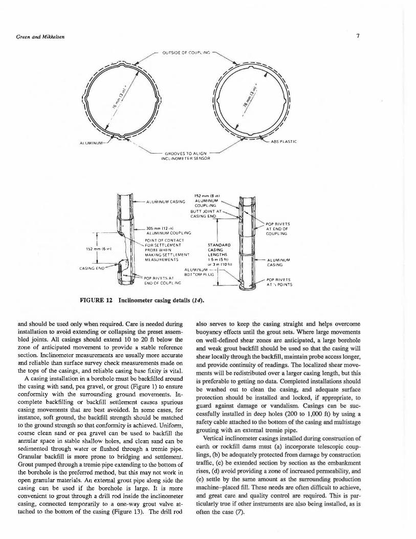
Green and Mikkelsen 7
~ GROOVES TO ALIGN INCLINOMETER SENSOR
152 mm (6 on)
ALUMINUM CASING ALUMINUM COUPLING
BUTT JOINT AT
-r -1
305mmfl2on) CASINGENIO
ALUMINUM COUPLING
POINT OF CONTACT FOR SETTLEMENT PROBE WHEN
POP R !VETS AT ENO OF COUPLING
152 mm (6 m)
CASING ENO
MAKING SETTLEMENT MEASUREMENTS
STANDARD CASING LENGTHS I 5m 15hl or3m(10ft)
POP RIVETS AT ENO OF COUPLING
:~~~~~up~~ I 1
ALUMINUM CASING
POP RIVETS AT.,, POINTS
FIGURE 12 Inclinometer casing detalls (14).
and should be used only when required. Care is needed during installation to avoid extending or collapsing the preset assembled joints. All casings should extend 10 to 20 ft below the zone of anticipated movement to provide a stable reference section. Inclinometer measurements are usually more accurate and reliable than surface survey check measurements made on the tops of the casings, and reliable casing base fixity is vital.
A casing installation in a borehole must be backfilled around the casing with sand, pea gravel, or grout (Figure 1) to ensure conformity with the surrounding ground movements. Incomplete backfilling or backfill settlement causes spurious casing movements that arc best avoided. In some cases, for instance, soft ground, the backfill strength should be matched 10 the ground strength so that conformity is achieved. Uniform, coarse clean sand or pea gravel can be used to backfill the annular space in stable shallow holes, and clean sand can be sedimented through water or flushed through a tremie pipe. Granular backfill is more prone to bridging and seulement. Grout pumped through a tremie pipe extending to the bottom of the borehole is the preferred method, but this may not work in open granular materials. An external grout pipe along side the casing can be used if the borehole is large. It is more convenient to grout through a drill rod inside the inclinometer casing, connected temporarily to a one-way grout valve attached to the bottom of the casing (Figure 13). The drill rod
also serves to keep the casing straight and helps overcome buoyancy effects unLil the grout sets. Where large movements on well-defined shear zones are anticipated, a large borehole and weak grout backfill should be used so that the casing wiH
shear locally through the backfill, maintain probe access longer, and provide continuity of readings. The localized shear movements will be redistributed over a larger casing length, but this
is preferable to getLing no data. Completed installations should be wasb.ed ou1 10 clean the casing, and adequa1e surface protection should be installed and locked, if appropriate, to guard against damage or vandalisnL Casings can be successfully installed in deep holes (200 co 1,000 fl) by using a safety cable attached to the bottom of the casing and multistage grouting with an external tremie pipe.
Vertical inclinometer casings installed during construction of earth or rockfill dams must (a) incorporate telescopic couplings, (b) be adequately protected from damage by construciion traffic, (c) be extended seccion by section as the embankment rises, (d) avoid providing a zone of increased penneability, and (e) settle by the same amo1mt as the surrounding production machine-placed fill. These needs are often difficult to achieve, and great care and quality control are required. This is particularly true if other instmments are also being installed, as is often the case (7).
8
RUBBER GASKET
CHECf< VALVE
GASKET SEAL TYPE
:; !'.
MOOIFIEO FEMALE OUICK.CONNECT COUPLING WITH
CHECK VALVE
: : . COUPllNG WITH _; Qf. MAl.E QUICK-CONNECT
:: : CHECK VA.LYE ,; . :
HEAVYOUTY {OJ: ;: PROTECTIVE CAP --.., , .: r . ' .
. '
PIPE CAP
FIGURE 13 Grout valve for Inclinometer casing Installation.
Horizontal inclinometer casing is usually placed in compacted fill beneath an embankment or structure (4, 5). The casing must be straight, with one pair of grooves vertical and preferably on a constant flat, free-draining grade so that the casing can be washed out. The instnunent is pulled into the casing with a steel cable. If access is available only at one end, the cable should be passed around a dead-end pulley and retur:ned in a second small PVC pipe .. alongside the casing.
Inclinometer casings can be cast into concrete piles, grouted into hollow core concrete piles after driving, attached to steel sheet, H, or pipe piles, installed after driving in steel tubes, or grouted into slurry walls. When the inclinometer is being used to monitor wall deflections of any type, it is advisable to extend
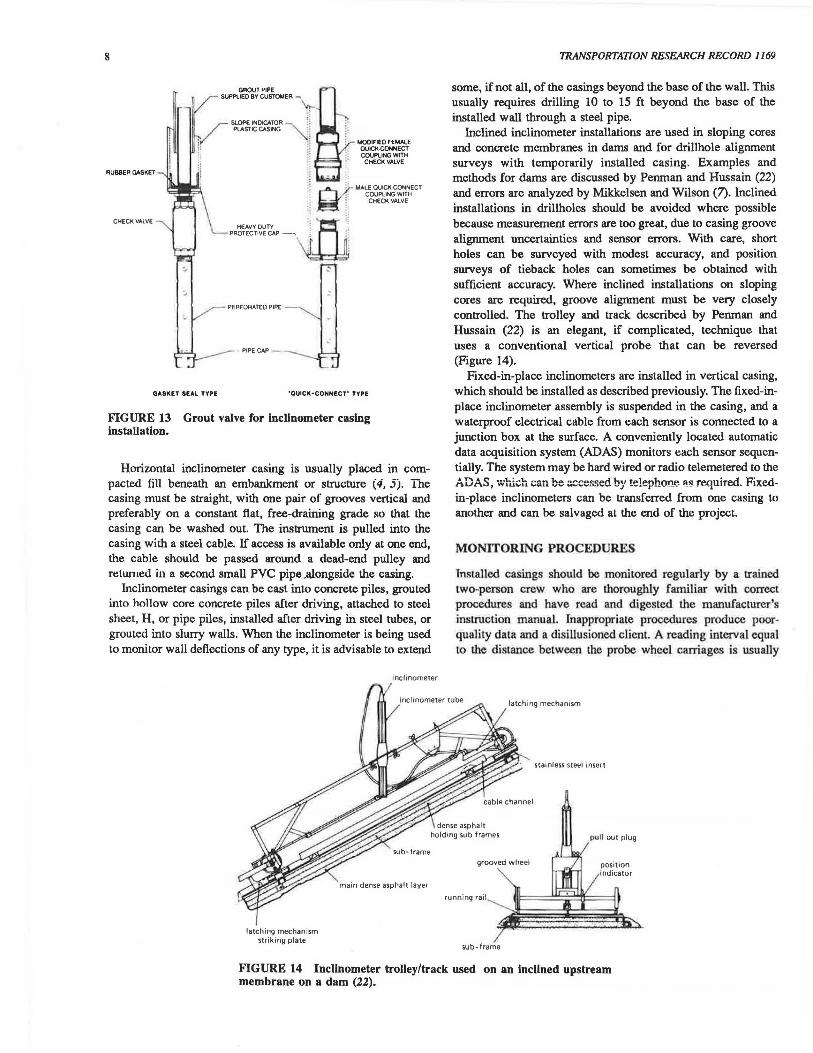
latching mechanism st riking plate
inclinometer
mai n dense asphalt layer
TRANSPORTATION RESEARCH RECORD 1169
some, if not all, of the casings beyond the base of the wall. This usually requires drilling 10 to 15 ft beyond the base of the installed wall through a steel pipe.
Inclined inclinometer installations are used in sloping cores and concrete membranes in dams and for drillhole alignment surveys with temporarily installed casing. Examples and methods for dams are discussed by Penman and Hussain (22) and errors are analyzed by Mikkelsen and Wilson (7). Inclined installations in drillholes should be avoided where possible because measurement errors are too great, due to casing groove alignment uncertainties and sensor errors. With care, short holes can be surveyed with modest accuracy, and position surveys of tieback holes can sometimes be obtained with sufficient accuracy. Where inclined installations on sloping cores are required, groove alignment must be very closely controlled. The trolley and track described by Penman and Hussain (22) is an elegant, if complicated, technique that uses a conventional vertical probe that can be reversed (Figure 14).
Fixed-in-place inclinometers are installed in vertical casing, which should be installed as described previously. The fixed-inplace inclinometer assembly is suspended in the casing, and a waterproof electrical cable from each sensor is connected to a junction box at the surface. A conveniently located automatic data acquisition system (ADAS) monitors each sensor sequentially. The system may be hard wired or radio telemetered to the ADAS, w·hich can be accessed by te!ephon~ ~~ requiTed. Fixedin-place inclinometers can be transferred from one casing to another and can be salvaged at the end of the project.
MONITORING PROCEDURES
Installed casings should be monitored regularly by a trained two-person crew who are thoroughly familiar with correct procedures and have read and digested the manufacturer's instruction manual. Inappropriate procedures produce poorquality data and a disillusioned client. A reading interval equal lo the distance between the probe wheel carriages is usually
latch ing mechan ism
stain less s te~I insert
p~ll out pl ug
grooved wheel
running rail
sub-frame
FIGURE 14 Inclinometer trolley/track used on an Inclined upstream membrane on a dam (22).

Green and Mikkelsen
most appropriate, allhough a greater interval may sometimes be used with little loss of accuracy, provided that thin shear zones are absent. Preferably, the same instrument should be used throughout the job because probes are not interchangeable wilhout generating systematic errors. Instrument damage or manufacturer recalibration may necessitate reinitialization of Lhe readings. Readings should be taken from the bottom of Lhe casing up, with close depth control (±1/• in.), by using a pulley wheel and cable clamp or similar device anached Lo the casing collar. In vertical casings, a uniaxial probe requires four passes up the casing, whereas only two passes are needed with a biaxial probe, which saves field time. The B-sensor data obtained wilh the biaxial probe are less accurate than those of the A-sensor (i.e., parallel to the wheels) because the side of the casing groove controls the B-axis sensor alignment. It is essential to obtain readings on both faces, that is, with the probe turned 180 degrees, to eliminate zero shift errors and enable data quality "checksums" to be computed. Checksums must always be computed and scrutinized for errors in the field. Where errors are suspected, repeal readings must be taken on the spot. In horizontal casings, Lhe uniaxial probe must be disconnected from the cable and reconnected to the second socket at Lhe other end of Lhe probe to reverse the probe, and only two passes are needed.
H casing spiral is suspected to be of significance, a spiral survey tool should be used to survey the casings. All portable equipment should be handled with care and protected during day-to-day use. The back of a pickup truck is no place for a delicate instrument on a rough site; instruments require "tender ~oving care" for good results. The cable should be protected from nicks, and connectors must be kept clean and dry. Although most probes and readouts are rated for a reasonably broad temperature range, neither should be left unshaded in hot climates or exposed to prolonged temperatures close Lo or below freezing point. Battery life at low temperatures is considerably reduced, dependent on type (23). Electronic component malfunction is more likely under extreme environmental conditions.
FlUlction checks on the instrument are necessary. Hanging the probe freely on 6 ft of cable gives a quick daily zero check, and regular readings in fixed short casings are desirable. Manufacturer adjustment, maintenance, and recalibration are advisable once per year or if instnlment performance is suspect. The instrument must be cleaned and wheels checked for excessive wear and oiled daily. Where practicable, periodically washing out the casing will remove grit that can collect in the grooves and cause increased groove wear, degrading data quality. Periodic surface surveys of both line and level at the casing collar provide an important check on measured gr01md movements and should always be made. If possible, where high accuracy is needed, duplicate sets of inclinometer readings should be taken and an average data set determined.
Data should be reported in an initial installation report, followed by monitoring reports (13). The installation report should include equipment model and serial numbers , calibration, description of installation, site plan with casing local.ion, elevation, groove orientation, convention adopted for Lhe sign of the movement and probe orientation, initial data sets, and a spiral survey, if one was taken. Each monitoring report should
9
include equipment model and serial number, data set, a dinry of field activities, and observations related to the installation. Jobs may extend over many months or years, and detailed records can be crucial when personnel changes or problems arise.
Where manual readings are taken, data are recorded on a field sheet formatted for computation or computer key entry (Figure 15). Face errors for pairs of corresponding readings (i.e., A+, A- and B+, B-) must be det.ermined and should be relatively constant at each depth. This provides a critical field check on data reliability. A similar procedure muse be followed with an electronic notebook or a computer-based readout, such as the Digililt RPP. Field equipment or procedures that do not permiL on-th~spot data quality checks should never be used. Two or three initial data sets should be obtained on a casing before any construction activity to ensure reliable baseline data and confirm that backfill movements are absent.
INCLINOMETER DATA SHEET Slnoo::::..--:-.:=:;m ~ .. ~
• • • .. ..... ' .... . .. - .. .. ' .. ft - , ... ·-·
IW .. q !i ,. .a. - A. I IH I ~ I p e. _A. II , ,. ·- ,,. ., .Ji M.l. IAti F-. Q).ICllHlll Q)M:>altlU lllil.l('lltPC)T.-UCOl.. tOI MOV..,lr
~ - 1 ~7 , 'di•.o< T, 16~~ .1.ofu. '19 · I ) tQ.l.Na 4 S(tHo >DA'( •TOK t Sl&T l~ f
1-•·.-----.----.-----.----.------, DEPTH DIR A+ OIR A - OIR 8+ DI R 8-
11' ~ 1--~~;~~~~~~u.2~~"'!-.......c~~.?~"'t-~~-~~.~~ol--~-~~~·':"'-i' ~"""'°"' ~ ·D 'Z, 7 .D - i t!J ~ ~ () 'l _. J q ~ -C(~ .,. ...., 'Z '- '1 - 2. -" _4 ,., -... ~ - 2 3- a;.
./.}. Z.. '- ~ - '1 6 1 " "" - 1. !I
I .d .o 7 ~ _.d - '1 ~ .d I '.!!a. 0 • t ~ J
t t} ..n 't' .:Z. .. "1 ~ 0 I n I D d -i. n .o '2. 4;o - '1 "> - :J
OICITUKJlDfl-'---'"'·~2~-""'l-~~~·o=w~>l-'-~-~~~b.,,....1--~~""l-~--'~ MOOt:L~'" 1--~•~•~~"'f.-~~·~~'·.ii-~~-~•u~~o1--......._~.~' A'!-I-......_.....:......,_,
1 .h . o ; 4 b ... _4 . .-:7_6 - J .fl .(, ~ ... o .. ._~ - J ~ • - " G < I
. 3 -~-o a. 7 e - .z e J 1 L'J - , 1 h"' Z6.1 - '2.i .l! I .t=. 11 - 1.~.7
4~.n I.A.~ -16 - ~ 1~0 - J 9_, t - 1 ..d . li,O .ll ~ - . I llF' 0 I . "1 J ... ~
POL.AAITY r;y .II 0 .r.:l - l 1 .,. I '1 I 4 j - / t. . ~
TU AHGll 1--~~ .... L')"''""o 1--~•,_.,_.1 "04-...-.:-"""""'=" <;'1--'-~ ........ ·<>:.j.. ·..._.~- .o...' ""L""lo
~-~~~~---~~~ ........ ~~.~~~ .......... ~~~ ~·+-"~~---t~~.~~~~-'-1
FIGURE 15 Field data sheet formatted for keypunch data entry.
Computer-based field readouts are being used more widely because they provide convenience, reliability, elimination of data transcription errors, on-the-spot computation of casing position or displacement, and cost savings. A recent cost comparison (24) indicated a tenfold reduction in monitoring costs when use of a Digirilt RPP was compared with use of manual equipment.
Monitoring telescopic casing where large axial displacements occur poses difficulties in repositioning the probe in the casing. If readings are made in the normal way at uniform depth intervals, the absolute profiles must be compared graphically. If a separate settlement survey is performed, computational techniques can be used to compare the two data sets.

10
Alternatively, the probe may be relocated at the same position in a casing section by "feeling" the casing coupling as the wheels pass through. Again, a separate seLLlement survey is required Additional bookkeeping complications occur when casing is built into an earth or rocldill dam because the reference point from which measurements are made is constantly changing (25) and reliance is placed on surface surveys. As yet, there is no better solution to this problem.
Fixed-in-place inclinometers should be read daily after installation to check for zero drift of a bad sensor. Depending on the readout arrangements, threshold readings and alarms may be set and telemetry systems may be checked. Automatically collected data should be scrutinized periodically for errors, particularly drift, and periodic probe inclinometer surveys should be made on an adjacent casing (Figure 16).
DATA PROCESSING, ERROR SOURCES, AND ACCURACY
Data checksums (i.e., algebraic sum of pairs of readings 180 degrees apart) must be computed and scrutinized in the field, and data should be processed as soon as possible. Manual data
P'ocld Data ml D;.placemonta ------·-
TRANSPORTATION RESEARCH RECORD 1169
1120 ...mr1120
w - DOWNSTREAM
"' 2 w a: w 1080 "' a: .. 0 u
Elev w I 1040
"' lee\ 2 w a:
4 w 3
z 1TI 1 I u: 1000
2 EL 995 EL 990
Inclinometer 1111!
sensors wtlh connecting 960
rods 1 5 1 0 05 0 05
01 splacement 1n inches
FIGURE 16 Horizontal movements measured with probe Inclinometer and with fixed-In-place Inclinometer In adjacent casings (26).
reduction is tedious even with the help of a programmable calculator, and many users recognize the advantages of computerized analysis (24, 27). IBM-PC software is now available; for example, Slope Indicator/Geo-Slope PC-SLIN, with keyboard or RS-232C serial input, tabular and graphic output, error
PC-SL IN --~------- -~-~-------~--------------------80~26------------------~
IE~ EXAl'IPLE NO. I DIGITILT DATA
PAST PRESENT
FIL£ -S JOB M.tUIER HOU: IUUIEA DA TA SCT NUl'1BER DATE TlllE READIN89 ~R DIRCCTION INST"RUENT ~ CONST~ ERROR llNGLE - A COl1P. ERROR MIGl.E - 8 C011P. ZERO SHIFT - A COl1P. ZERO SHIFT - 8 C~.
PAST DATA
A:Sll.SN W-25S3-0l a-1 7 SEPT 20173 13110 2 039
20000. .ooo .000
PRESENT DATA
At Silt. SN W-25S3-0l 1-1 7 OCT. ll/711 12:30 2 039
20000. .000 .000
0 0
Total Dellectlon belweMI the PAST and PRESENT sets or data
~ PAST OIFF.
PRESENT Df:"FL. DEPTH FT. A+ A- A+ A- DIFF. CHANGE IN.
in -179 ~ 124 -12:5 249 -107 I. 0149 2.0 202 -l9S 397 210 -188 398 1. l 112 4,0 211b -293 S49 270 -283 ss= 4 I. 1106 6.0 2S9 -261 S20 267 -264 S3l 11 l . 1082 8.o 254 -249 S03 263 -2:51 Sl4 II l.1016 10.0 247 -248 49:5 246 -24S 4'1 -4 J.09:50 12.0 237 -236 473 234 -234 468 -:5 l .0974 14.0 234 -247 481 241 -24S 4911 s I. 1004 111.0 25S -256 Sil 252 -2:50 S02 -9 l.0974 19.0 243 -2:57 soo 251 -2S9 SIO 10 1. lO::!B 20.0 26.7 -279 S46 21.3 -:?66 s~ -17 l .0969 22.0 313 -319 632 319 -320 639 7 1 . 1070 24.0 33S -328 61.3 346 -3Z!I 1.74 II l . 10::!8 26.0 3112 -362 724 ~55 -!54 709 -1:5 1.0962 29.0 288 -294 :582 299 -:?SS S84 2 l.10~2 30.0 211S -211b S3l 936 -·~ 1872 1341 l .1040 32.0 283 -279 :562 S49 -SS3 1102 S40 .:?994 34.0 2'90 -234 S24 299 -277 Slob 42 -.0241. 36.0 273 -281 SS4 278 -283 :5111 7 -.0498 38.0 271 -2119 S40 2113 -::.?58 :521 -19 -.OS40 40.0 194 -19:5 389 194 -193 387 -::! -.o4:6 42.0 112 -187 3119 193 -183 3116 -3 -.0414 44.0 190 -192 382 190 -190 390 -::! -.0396 411.0 1711 -17S 3Sl 170 -171 341 -10 -. 0384 48.0 200 -203 403 210 -20s 41S I:! -.0324 so.o 2:?1 -223 444 219 -219 439 -6 -.03911 :52.0 224 -237 4111 :!..."':5 -239 4114 3 -.03110 S4.0 2:54 -21>0 S14 253 -2:50 S03 -ll -.0378 Sb.O 192 -197 389 189 -191 379 -10 -.0312 se.o 240 -2111 SOI ::!:53 -267 S20 19 -.025:? 110.0 224 -231 4:5:5 213 -215 4::!9 -27 -.03116 112.0
FIGURE 17 Tabulated computer output.

Green and Milclulsen 11
Data Qualit.y Chock ond Statisticol Routino M.IL1,.SIO( A-..DUCTtA..CNOlt .. Wllf
OltlTILT DAU
&•T•n.lll(NT ~ltFOllll•aNt[ CtCCll.
MOl.l ......-r.• ·-· 1 ... nui.. ~' ...,..,,. I C\Mlltlfrlf Ut ...... 7 l"ltlAL DUE 1051:~.n C~UNT OAH UOCTtft
INITIAL DAU CUHllNf OIU ltlllTIA6. DATA '-"lNT DUI ------ .... _________ --------1111111 .... DI .. '" INJr CIMO Ol"M . , .. ,_ ., .. .... Dllll'F ... •• .. - •• .. .... Dllll'lll' "· 117 -•" -· ... •U!t -· 1 ... ... _,,. -s .. . . ... • ••• ••• -••!t ' ... .... .. .. ... . .. -111 . Ill •HS ... .. ... ••• •l•l
_., '" •Hl -u • ... ... ... , I ,., .... • • • •• ... -1•1 -· .. , •Ult ' • ... . .. .... _, ... -us • ' ••• ••• ·1•9 • ... ·2!tl u ' u1.w ••• •Ho ... . .. •i&I -ao • • ••• .. , ... , ... -· .. , -ai.!t • 11.u ••• -an -u ... •lH ' .. .. .. .. , _,,. 1 ... -u- -· l••U U• .... ... uo •UI -· • .... ... ..., .. 1 •IJ ••• -i·~ -· • ••·a 111 -uo .. II• -111 ' u • ••• ZS~ •l!tlb -· 2~1 -.uu 1 • 11.u IOI •189 ... •&01
_, _, 11.0
;!Ill -u1 -·· ... -n• -· • ID•\J .. ..... -11 •• . .. -n • • ••• .. , ... ,.,. _,, .. , .... _, • 11.D ID ... -u • - 1 u .... .. , -sat ... ... •.Hll -· • , •• a •• ..,, -11 •• . .. -· u .. .. ,., ·)21 ' ... •HI 11 11 , •• o •• -· u -·· •• _, -u .... ... .... • ... .... I I 11.0 •• ..... -· ..... .. , • .. .. ... ... , .. -· ••• •.ll!t .. •• JD.lot •• -· II .. .... .. ID .. .. ••• -1•• -· ••• .... • I Ja.u U• _,,. ... • -11 -u I ,.,, ... -119 . ... •Hl -· -· , .... " "' . ... _,. .. . ... , -· " ,.,, ... .... .. ••• -in 11 .... .. .. 110 -u• .. .. . •H• • u .... .,, •Ill ... .,. -au .. • , •• o II• •lH -·· ... -11• -· • .... ,,, .. , .. l ... .... • • •o.o ... .. .... . ... •U7 11 • .. .. ... •19! -· ... •lU I • •l•D ... •lH -·· ... •lU -· • •••• U.t: .. ,., -· "'' •lll • • ••• o ,., .... -11 ... . ... ... ' .. .. ... •ltl -· ••• ·&•u • • ••• o '" .... ... IU . ... -u I .. .. ... •lH 1 .,. ...,, -· -· ••• o ... .... -n • •• .. .. , ... II .. .. ••• -10.s -· 11n •II! • I !to.o ... •lll
_,. .,. -a•o -·· I .. .. ... .... , -· ... .. , .. • • .... 17J ..., . _, an -uo _, .. .... ... _,,, _., ... ·.U• -·· -· ... .. lti ...... _, ... -1•1 -· I .. .. ... -1•0 .. ... •HO ' • .. .. .. . .... _., .. . .... -· ' .. .. ••• .. ,., -· ••• -1•1
_, ''·" .. ... -· .. ... . • ....
••• ..,., -11 '" .... , ... ••• o ... .... _,. .., -an ... • .... ... _,,, _, llJ -au -· .... U) .... -· 111 •lll ·• ) .... ... .... _, ... •lU
_, ... • •• o ... -u• -u "' .. ... .. I .... ,., ...... _., '" ..... ... -· .. .. ... -111 .. .,, •llt .. .. .... .. , _,, .. _, ••• .... -· • .... ... •IU .. ... •llO -·· _., ....
••• ..... -11 ... -1•0 .. • 1u.a Ill _.,
II ... - .. ' ''·' ••• •llO ... ••• •IH , • Ta.a ... .... -n '" . ... -u ,. .. ••• ·101
_, ... -102 .... -· ., •• o ,., ·l7• -11 '" •110 .. , .. , ,., .... -· ... .... ' ,,.a . .. •U7 -·· ... .. , .. •l , ...
D"UILT oau
llt\,1111,,.lJill'f •UFOllllllf&""[ c~c~ ~AlllT STIUS.TIC~
l"llfUL IU ~· l '"""'"' "' ....... ' 1 .. 111.aL o.nE aow•.n tl.lllllllNT OAfl llDCftH
... ... --------··-·--·-·-··-··-··--··--·-·--····-··- ···--···-····-··-- ·-···-.... --........... -........... -...... INITIAL SUll--·-- lf.M•l~' s.u--•--01,,r•rNCl·-· I- HUlUL ~-I·- ,...,..,,., iUW••l---Ol,,l•[frilCC•-1
"D• STD• INl[lllW&L .... .... .... oc. • ....
1·0 '" ZDoD .. .. . .. .. l1o0 '" -.o.o ... .. .. O• 1112.a ,. •a.o -·· '· -·· '· ). •a.o '" l•.a -1. .. .... .. .. ["TUl ._O...t. -·· ... -·· .. ..
FIGURE 17 continued.
detection routines, and systematic error correction features. Readings can be input manually from hand-recorded data sheets or by RS-232C serial input from magnetic tape when recorded automatically, as with the Digitilt RPP.
Processed data (Figure 17) should be scrutinized by using error detection and correction routines to optimize the data quality and enable correct interpretation of engineering behavior. Graphical data presentation is essential and may include (a) slope change/depth, (b) displacement/depth, (c) displacement/time for a specific depth interval, and (d) displacement vector plots on a site plan, in that order (Figures 18, 19, and 20). Construction activities and instrument field crew observations should be noted on the plots to aid interpretation. Ground movements are usually progressive and continuous in one direction, although the rate of displacement will generally not be constant. Erratic displacement/time plots should always be carefully investigated. Figure 20 shows steady state creep in a reactivated ancient slide, whereas Figure 21 presents a
U'l. .... .. "· .. .. ..
sro. "O• ITDo .... .. .. .... OC•• CAN IX•• .... . . -·· .. .. . . .... ... .. ... .. .. . •llo .. ... .. .. .. -1. .. . -·· . .. .. II•
-·· ... -·· ... .. ..
decreasing deep-seated movement rate, that is, a more stable condition developing.
A wide range of random or systematic errors can occur, both obvious or subtle. Experience indicates that data interpretation is often difficult and that wrong conclusions are drawn concerning magnitude and locations of movement. Both authors have extensive experience in trying to diagnose errors and draw rational engineering conclusions from conflicting and inexplicable data, not always as successfully as desired. Errors arise due to equipment faults, user misuse, or mistakes, as well as recognized system limitations.
Equipment problems include sensor malfunction, wheel bearing wear, low batteries, moisture ingress to cable connections or readout, mechanical shock damage, nicked cables, improper casing installation, calibration changes inherent in manufacturer servicing, and cable stretch or marker movement with use. User errors arise due to reading errors and data

PC-ILIN
IEJCH'WtK £1AfPL..£ trCJ. I DIGITIL T DATA
MOL.£ ...,._,., ·-• PA9T F'ILE .... 1A1911.SN PA91' 8S'T ~· 1 PA9T DATE1 8EP'T 2011'3
A-
PftESENT F'ILE NNE1A19111.SN PftESENT SET M..l'IBEfh 7 PAl:SDfT DATE• CX:T. II /76 ...
DtANBE JN READINS -900. -i.oo. -300. o. 300. 900. ----- --------·---------·-------·--
• " 12.0
" " • " 22.0
" • l2.0
I II
" 42.0
• " • " 52.0
" " ,, 6.2.0
" " " 72.0
" II
•
GEO-SLOPE
SERIAL NO. 85019
HOLE -BER: S-1 PAST FILE NAl1E: A:BNl.SI
FILE NAl1E: A:BN2 . SI
FILE NAl1E: A:BN3.SI
~!Lio -· A:llN4.91 FILE NAf'E : A: 8N~. SI
FLLE lllAP1E1 A:BNb.SI
A-
PC-SLINI ---------90:S:?A------------
8ENCMWae E:I~ NO. l DIOlTILT DATA
H0L£ ~RI 9-1 P'AST FU • .£ HAl'C1A1Sll.SH PAST SET ...... 8E1'1 1 PAST OATE1 9EP"T 20173
PRESENT FILE HN'E:AtSlll . SN PRESENT SET hUP'IKfh 1 PftESENT DATE1 OCT. ll/76
A- A• DEF\..ECTION - IPCHE9
-. 7~ .000 . 7SO 1.~00 ·-- - -------·--·------------I I I I
11 . 0 I I I I
21.0 I I I I 3:;.--
PC-SL IN
11 II II .. " " " " " " .. .. " .. " " •I
" " " "
PAST DATE: NOV.lb/82 DATE: HAY.18183
DATE: JUNE.14/83 DATE: Jll Y 11 /93
DATE: AUG . 22/83 DATE: SEPT 27/93
A+
DEFLECTION - INCHES
41.0
51.0
6.1.0
71.0
x
•
.000 1.250 2.500 3.7:SO -·------+---------·--------+-- --' I
11.0
l 2 1.0
I I
l l.O
I lo :s!.o I
I bl.O
71.0
81.0
91.0
101.0
FIGURE 18 Graphical computer output: (top) single data set, (bottom) multiple data set.

Green and Mikkelsen
\ \A· \.-mim Jr --Ii lllDI IDUIDlll
ID 11111111
11 11
llr!IUI ltlll II lltMll
'
\t \.-1111111
·& IL IDI
lllllDUI
.. 11111111
I ID I 1G
1111 If IOll•11 Still II lltNll 1111
::;
FIGUR.E 19 Vector plots or slide movements showing magnitude or movement January 1976-April 1979 and average rate of movement January 1978-April 1979.
transcription errors where manual methods are used; incorrect probe orientation in the casing grooves; probe depth position errors due to careless reading techniques, surface casing disturbance, or incorrect matching of readings 180 degrees apart; incorrect assumption of casing base fixity; unrecognized settlement or heave; improper reading techniques; or lack of survey control when telescopic couplings are used or when large settlements or heave must be accounted for. This is a formidable list of problems that can and do occur, and good project planning, equipment selection, training, data scrutiny, and awareness of the pitfalls are needed to avoid them.
If it is assumed that equipment and user related errors can be recognized and controlled, measurement errors also exist because of the inherent limitations of the best available instrument and casing. The data quality tabulation (Figure 17) is an essential aid and should always be used. Variation in checksums can be quickly scanned, errors detected, and data quality assessed. The statistical analysis provides a useful comparative
13
instrument performance rating. If opposite walls of the inclinometer casing are not quite parallel, if any wheel is in a coupling, or if depth control is imprecise, the checksum may vary randomly. Small variations are tolerable.
Ideally, checksums should remain constant with depth within a given data set for both A and B sensors. If a change in the zero offset occurs between sets of readings, the checksum will change, but this does not matter. If a change occurs in the zero offset during a particular set of readings, either during a traverse or between opposite traverses due to temperature or shock-induced changes to the sensor suspension, the result will
INCLINOMETER CASING GROUTED IN PLACE 0 35 e A DIRECTION
OI B DIRECTION DISPLACEMENT BETWEEN 31 & 33
0 30 FOOT DEPTH INTERVALS
Ul 0 25 w I 0 2 ~ O.?.O 2 Q t> 0 15
~ 11 ~010 M
;:::~ 00 WW
O OS g;g; 00
00 I
INSTALLED 4-10-76
0 12 INCHES/YEAR
KSUBSTITUTE INSTRUMENT USED •
FIGURE 20 Creep movements on a thin shear zone In a reactivated ancient slide.
INCLINOMETER DHS-1
LATERAL t.AOVEME NT l04 n TO 122 Fl DEPTH
NORTHERLY ) M[.t.SUREi.IENTS OISCONTINUEO DEFORMATION DUE TO BLOCKAGE IN CASING
(: AS1EPP: DE.F~MAT1Qp.;
INCLINOMETER DHS - 2
LAT ffiAL ""OVEMENT S20 FT TO 530 n DEPTH
.... ....
FIGURE 21 Deformations measured on deep shear zones on a landslide in Canada.
be errors that can only be eliminated by careful scrutiny and computerized error detection routines (Figure 22). When readings are obtained in slightly inclined casing, a correction for changes in the servo-accelerometer azimuth orientation may be required. Slight changes in the sensor due to shock occur from time to time. These changes show up as irregular rotation of the displacement/depth profile (Figure 22) and can mask shear occurring at discrete zones. The combination of sensor azimuth rotation with inclined casing causes systematic errors. Individual correction angles can be applied to the A and B sensors of each data set by using computerized routines and shear zone

14
movement correctly identified (Figure 21). Although sensor zero shifts are a significant problem and must be properly dealt with during data processing, the scale span or slope of currently available servo-accelerometers is fairly stable, and errors due to this source appear to be less serious. They cannot be eliminated by routine procedures and require instrument recalibration by the manufacturer. Some manufacturers provide simple field calibration frames, but these appear to be of limited value.
NO CORRECTION WITH ZERO SHIFT CORRECTION
CHANGE
NO COAAF.CTION
DEFLECTION A AXIS
DEFLECTION CHANGE
CASING PROFILE 8 AXIS
!CROSS AXIS 1NCL1NATION1
r v
DEFLECTION
CORF~ECTEO
OE:FLECllON A AXIS
FIGURE 22 Typical zero shift and rotation errors.
Errors can arise immediately after installation due to settlement of the backfill. Erratic casing movements develop but usually cease with time. An extreme type of error can occur where drilling and grouting upset the stress and thermal regime of the surrounding material. Casings installed on a permafrost slope to monitor slope creep have shown extraneous movements due to recovery of thermal equilibrium around the casing, effects of stratigraphy and settlement, and heave of the casing (28, 29). High-quality monitoring procedures and painstaking analysis were employed that enabled definitive slope velocities of 0.30 cm/yr to be established. Other data filter techniques have been suggested (30); however, caution is urged in using statistical techniques.
Similar principles to the foregoing apply to horizontal inclinometer casings. Where access is available at both ends of the casing, first-order leveling is used to convert the inclinometer survey to a closed traverse, and settlement measurement accuracy is greatly increased. Inclined casings used to monitor displacement pose special problems (7) that require consideration of (a) groove spiral, (b) initial groove roll angle at the casing collar, and (c) sensor azimuth changes. In addition, if absolute position is desired, the azimuth of the vertical reference plane is determined by surveying the casing collar. Fixedin-place inclinometers are subject primarily to sensor drift errors, and slope change/time plots for individual sensors should be scrutinized.
Measurement accuracy achieved with inclinometer systems is highly dependent on (a) the equipment selected, (b) the installation and monitoring procedures used, and (c) correct data scrutiny and processing. The system accuracy or precision
TRANSPORTATION RESEARCH RECORD 1169
achieved is quite different from the quoted resolution or sensitivity of the probe and readout. The inclinometer measures relative movements, so it may be more appropriate to discuss performance in terms of precision, that is, the repeatability with which the instrument can determine the position of one end of the casing relative to the other. A servo-accelerometer-type inclinometer system is capable of a precision of ±0.05 to 0.25 in. over 100 ft in vertical and horizontal casings but much less in inclined casings (7). It is, of course, rare for an accurate independent check to be possible (12), and estimates of precision or accuracy achievable are based on a combination of direct measurement, experience, and reasonableness of the data.
PLANNING AND EXECUTION OF INCLINOMETER MONITORING PROGRAMS
As with all geotechnical monitoring programs, inclinometer measurements must be properly planned and executed. Too often instruments are installed for ill-defined reasons, and data are collected and filed away, unused (10, 31). Instrumentation has become fashionable. In contrast, real needs should be assessed, behavior predicted, and tasks assigned following a systematic approach. What needs to be measured, the accuracy required, and if and how this can be achieved should be considered. Specialist advice on instrumentation system design should be sought where in-house skills are lacking. The engineer is usually the party most interested in obtaining reliable monitoring data and should retain as great a control as is possible. In general, instrumentation should not be left up to the contractor.
Descriptive or performance specifications for instrument procurement may be used (JO, 31, 32). Too often n single lump sum bid item appears in a specification for supply and installation of a variety of instruments, and the low bidder wins (7). Under these conditions the engineer often ends up with something far less than is needed, even though considerable sums of money have been expended. It is preferable for the engineer to select the make and model number of instrument believed to be most suitable and to specify with no substitution allowed. Sole source justification may be required and can be used (33). The inclusion of "or equal" leads to excessive emphasis on low cost so that high-quality instruments are excluded (34, 35). There is often no good, legally defensible way of excluding substitute instruments. An entire inclinometer monitoring program may fail if an inferior instrument is selected. This is not an acceptable risk and hence must be avoided. Detailed procedures for minimizing these risks are discussed elsewhere (10, 31).
CONCLUSION
The inclinometer is widely and successfully used to measure ground movements and is capable of considerable accuracy. Successful projects require good planning, high-quality and appropriate instruments, proper installation, diligent reading, correct data processing, and intelligent scrutiny and interpretation. Cooperation and understanding between engineers, clients, and contractors is essential for success.

Gree11 and M iklulse11
ACKNOWLEDGMENTS
We are indebted to our colleagues for support. We are also grateful to our clients, through whose projects we have come to better understand many of the problems of instrument performance and subtleties of daca analysis. These experiences led to the improvements djscussed in !his paper. The substance of this paper was originally presented at a symposium on field instrumentation organized by the Nanyang Technological Institute, Singapore, in November 1986.
REFERENCES
L S. D. Wilson. The Application of Soil Mechanics to the Stability of Open-Pit Mining. Quarterly of the Colorado School of Mines , Vol. 54, No. 3, pp. 93- 133, 1959.
2. S. D. Wilson. The Use of Slope Measuring Devices to Detennine Movements in Earth Masses. Jn Special Technical Publication 322: Field Testing of Soils, American Society for Testing and Maierials, Philadelphia, Pa., 1962, pp. 187-198.
3. W. P. Grant, G. Yamane, and R. P. Miller. Design and Performance of Columbia Center Shoring Wall, Seattle, Washington. Proc., International Co'lference on Tall Buildings, Institution of Engineers, Singapore, Oct 1984, pp. 651--661.
4. K. Omori, K. Komatsu, S. Ohya, and H. Nakayama. Measurement Results of Vertical and Horizontal Deformation of Large Oil Tunk. Proc .. 12th Annual Conference on Soi/Mechanics and Foundolion Engineering, Japanese Society of Soil Mechanics and Foundation Engineering, Tokyo, 1977, pp. 579- 582.
5. P. E. Mikkelsen. Horizontal Inclinometer Monitoring of Balsam Meadow Dam. The Indicator, Vol. 15, No. 1, November 1986, p. 25.
6. R. A. Robinson, E. J. Cording, D. A. Roberu, N. Phienwcja, I . W. Mahar, and 1-1. W. Parker. Ground Deformations Ahead of and Adjacent to a TBM in Sheared Shales in Stillwater Tunnel, Utah. Proc., 1985 Rapid ExcavaJion and Tunneling Conference, New York, Vol. I, American Institute of Mining, Met;illurgy and Pccrolcum Engineers and American Society of Ci vii Engineers, 1985, pp. 34-53.
7. P. E. Mikke.lsen and S. D. Wilson. Field lnsbUmenration: Accuracy, Performance, Automation, and Procurement In Proceedings, International Symposium on Field Measuremenrs in Georru:chanics, Vol. 1 (K. Kovari, ed.), A. A. Balkema, Rotierdam, The Netherlands, 1983, pp. 251- 272.
8. W. Tesch. AutomaJed Borehole SUTVeying System for Steeply Inclined Cased Boreholes. Rcpon of Investigations 8156. U.S. Bureau of Mines, U.S. Department of lhe Interior, 1976.
9. G. W. Uttecht and J. P. deWardt. Survey Accuracy is Improved by a New, Small OD Gyro. World Oil, Vol. 196, No. 4, March 1983, pp. 61-64.
10. J. Dunn.icliff. Geotechnical Instrumentation for Monitoring Field Performonce. John Wiley, New York, 1988.
1 I. I. P. Gould and J. Ounnicliff. Accuracy of Field Measurements. Proc., 4th Panamerican Conference on Soil Mechanics and Foundation Engineering. San Juan, Puerto Rico, Vol. I. 1971, pp. 313-366.
12. G. E. Green. Principles and Performance of Two Inclinometers for Measuring Ground Movements. In Proceedings, Symposium on Field Instrumentation in Geotechnical Engineering, Butterwonhs, London, 1974, pp. 166-179.
13. JSRM. Suggesied Methods for Monitoring Rock Movements Using Inclinometers and Tiltmeters. Rock Mechanics, Vol. 10, Nos. 1 and 2, 1977, pp. 81- 106.
14. S. D. Wilson and P. E. Mikkelsen. Field Instrumentation. In Special Report 176: landslides: Analysis and Control. TRB, National Research Council, Washington, D.C., 1978, pp. 112- 138.
15. Standard Method for Installing, Monitoring, and Processing Data of the Traveling Type Slope lnclinomete.r. In Standard Specifications for 1'ransportaJion MaJerials and Methods of Sampling and
15
Testing, AASIITO, Washington, D.C., 1978, T 254-78, Part II, pp. 941- 950.
16. T. H. Hanna. Field Instrumentation in Geotechnical Engineering. Trans Tech Publications, Clausthal-Zellerfield, Federal Republic of Germany, 1985.
17. C. L. Bartholomew, B. C. Murray, and D. L. Goins. Embankment Dam Instrumentation Manual. BW'eau of Reclamation, U.S. Department of lhe Interior, 1987.
18. K. Y. Nilsen, E. DiBiagio, and A. Andresen. Norwegian Practice in Insttumenting Dams. Water Power and Dam Construction, Vol. 34, No. 11. Nov. 1982, pp. 34-38.
19. D. J. Bailey. Land Movement Monitoring Sysiem. Bulletin of the Ass.xiation of Engineering Geologists, Vol. 17, No. 4, 1980, pp. 213-221.
20. 0. H. Cornforth. Perfomlllrlce Characteristics of the Slope lndicator Series 2008 Inclinometer. In Proceedings, Symposium on Field Instrumentation in Geotechnical Engineering, Buttcrwonhs, London, 1974, pp 126-135.
21. S. D. Wilson and P. E. Mikkelsen. Foundation Instrumentation: Inclinometers. Report FHWA TS-77-219, FHWA, U.S. Department of Transportation, 1977.
22. A. D. M. Penman and A. Hussain. Deflection Measurements of lhe Upstream Asphallic Membrane of Marchlyn Dam. Waler Power and Dam Construction, Vol. 36, No. 9, Sept. 1984, pp. 33-37.
23. D. Shoup and H. Dutro. Battery Powe.r for lnslJUmentation. The Jndicator, Vol. 14, No. 1, Deo. 1985, pp. 19- 22.
24. R. Thomas. Time and Cost Comparisons Between Slope Indicator Company Inclinometer Indicators. 1'he Indicator, Vol. 14, No. I, Dee. 1985, pp. 4-7.
25. S. D. Wilson and C. W. Hancock. Instrumentation for Movements Within Rocldill Dams. lo Special Technical Publication 392: lnstrumenls and ApparaJus for Soil and Rock Mechanics. American Society for Testing and Materials, Philadelphia, Pa., 1965, pp. 115-130.
26. G. E. Green and O. A. Roberts. Remote Monitoring of a Coal Waste Embankment Proceedings, International Symposium on Field Measurements in Geomechanics, Vol. 2 (K. Kovari, ed.) A. A. Balkema, Rotterdam, The Netherlands, 1983, pp. 671-682.
27. D. A. Barratt. Rapid Data Reduction and Ground Movement Measurements. Tunnels and Tunneling, Vol. IO, No. 3, April 1978, pp. 46-47.
28. N. R. MOJ&enstern. Geotechnical Engineering and Frontier Resources Development Geotechnique, Vol. 31, No. 3, Sept. 1981, pp. 305-365.
29. K. W. Savjgny and N. R . Morgenstern. In Sini Creep Properties in lee-Rich Permafrosr Soil Canadian Geotechnical Journal, Vol. 23, No. 4, Nov. 1986, pp. 504-514.
30. E. C. Kalkanl. Filtering Probe Inclinometer Data to Identify Characteristics of Slope Movement Rock MecJ1anics, Vol. 13, No. 2, 1980, pp. 57-69.
31. J. Dunoiclif[. NCHRP Synthesis of Highway Practice 89: Geotechnical Instrumentation for Monitoring Field Performance. TRB, National Research Council, Washinglon, D.C., 1982, 46 pp.
32. M. F. Kennard. Field Instrumentation Within a Civil Engineering Contract. Proceedings, Symposium on Field Instrumentation in Geotechnical En.gineering, Butterworths , London, 1974, pp. 220-228.
33. R. S. Perlman. Sole Source Contracts , Basic Principles and Guidelines. Briefing Papers 83 -7 , Vol. 6, Briefing Papers Collection 187. Federal Publications, 1.nc., Washington, D.C .. July 1985, pp. 187-222.
34. P. E. Mikkelsen. Discussion on "Piezometcrs in Earth Dam Impervious Sections,'' by J. L. Sherard. Journal of the Geotechm'cal Engineering Division, ASCE, Vol. 108, No. GT8, Aug. 1982, pp. 1095- 1098.
35. G. E. Green. Discussion on "Piezometers in Earth Dam Impervious Sections,'' by J. L. Sherard. Journal of the Geolechnical Engineering Division, ASCE, Vol. 108, No. GTl l, Nov. 1982, pp. 1526- 1528.
Publication of this paper sponsored fry Committee on Soils and Rock I nstrume11tation.