defender 5000 indicators service manual
TRANSCRIPT
Defender 5000 Indicators Service Manual
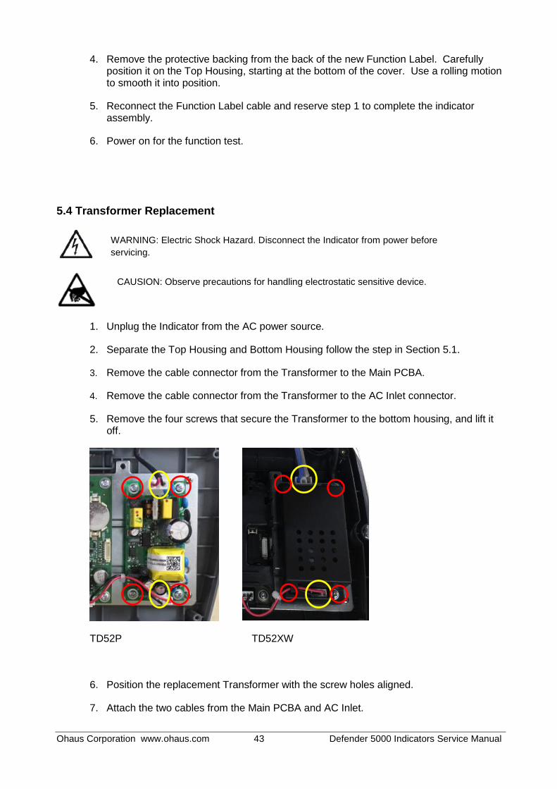
TD52P
TD52XW

Ohaus Corporation www.ohaus.com i Defender 5000 Indicators Service Manual
TABLE OF CONTENTS 1. INTRODUCTION .......................................................................................................................................... 1
1.1 DEFINATION OF SIGNAL WARNING AND SYMBOLS ........................................................................... 1
1.1.1 Safety Precautions .............................................................................................................................. 1
1.1.2 Relay Option Safety Precautions ........................................................................................................ 1
1.2 SERVICE FACILITIES ............................................................................................................................... 2
1.3 TOOLS AND TEST EQUIPMENT REQUIRED ......................................................................................... 2
1.3.1 Special Tools and Test Equipment List ............................................................................................... 2
1.3.2 Standard Tools and Test Equipment List ............................................................................................ 3
1.4 OVERVIEW OF PARTS AND CONTROLS ............................................................................................... 3
1.4.1 TD52P ................................................................................................................................................. 3
1.4.2 TD52XW .............................................................................................................................................. 4
1.4.3 MAIN PC BOARD ................................................................................................................................ 5
1.5 CONTROL FUNCTIONS ........................................................................................................................... 6
1.6 EXTERNAL CONNECTIONS .................................................................................................................... 7
1.6.1 Scale Base with Connector ................................................................................................................. 7
1.6.2 RS232 interface Cable to TD52P ........................................................................................................ 7
1.6.3 AC Power to TD52P ............................................................................................................................ 7
1.6.4 AC Power to TD52XW......................................................................................................................... 7
1.6.5 Battery Power ...................................................................................................................................... 7
1.7 Internal Connections .................................................................................................................................. 7
1.7.1 Opening the Housing........................................................................................................................... 7
1.7.2 Scale Base Without Connector ........................................................................................................... 8
1.7.3 RS232 Interface Cable to TD52XW .................................................................................................. 10
1.7.4 MICRO SD Card Installation ............................................................................................................. 10
1.8 TD52XW Rear Housing Orientation ......................................................................................................... 10
1.9 Mounting Bracket ..................................................................................................................................... 10
2 SETTINGS.................................................................................................................................................. 11
2.1 Menu Structure .................................................................................................................................. 11
2.2 Menu Navigation ...................................................................................................................................... 13
2.3 Calibration Menu ...................................................................................................................................... 14
2.3.1 Zero Calibration ................................................................................................................................. 14
2.3.2 Span Calibration ................................................................................................................................ 15
2.3.3 Linearity Calibration ........................................................................................................................... 16
2.3.4 GEO Adjustment ............................................................................................................................... 17
2.4 Setup Menu .............................................................................................................................................. 17

Ohaus Corporation www.ohaus.com ii Defender 5000 Indicators Service Manual
2.4.1 Capacity Unit ..................................................................................................................................... 18
2.4.2 Range ................................................................................................................................................ 18
2.4.3 Capacity ............................................................................................................................................ 18
2.4.4 Graduation ......................................................................................................................................... 18
2.4.5 Language .......................................................................................................................................... 19
2.4.6 Power On Zero .................................................................................................................................. 19
2.4.7 Power On Unit ................................................................................................................................... 19
2.4.8 Key Beep ........................................................................................................................................... 19
2.4.9 Transaction Counter .......................................................................................................................... 19
2.4.10 Password ......................................................................................................................................... 20
2.4.11 Reset ............................................................................................................................................... 20
2.5 Readout Menu ......................................................................................................................................... 20
2.5.1 Stability .............................................................................................................................................. 20
2.5.2 Zero Range ....................................................................................................................................... 20
2.5.3 Filter Level ......................................................................................................................................... 20
2.5.4 Auto Zero Tracking ............................................................................................................................ 21
2.5.5 Auto Dim ............................................................................................................................................ 21
2.5.6 ScreenSaver ...................................................................................................................................... 21
2.5.7 Auto Off ............................................................................................................................................. 21
2.5.8 Adjust Contrast .................................................................................................................................. 21
2.5.9 Reset ................................................................................................................................................. 21
2.6 Discrete I/O .............................................................................................................................................. 22
2.7 Weighing Unit ........................................................................................................................................... 23
2.7.1 Gram (g) ............................................................................................................................................ 23
2.7.2 Kilogram (kg) ..................................................................................................................................... 23
2.7.3 Pound (lb) .......................................................................................................................................... 23
2.7.4 Ounce (oz) ......................................................................................................................................... 23
2.7.5 Pound: Ounce (lb: oz) ....................................................................................................................... 23
2.7.6 Tonne (t) ............................................................................................................................................ 23
2.7.7 Ton (ton) ............................................................................................................................................ 23
2.7.8 Custom Unit (c) ................................................................................................................................. 24
2.8 GMP Menu ............................................................................................................................................... 24
2.8.1 Date Format ...................................................................................................................................... 24
2.8.2 Date ................................................................................................................................................... 24
2.8.3 Time Format ...................................................................................................................................... 24
2.8.4 Time................................................................................................................................................... 25
2.8.5 Project ID ........................................................................................................................................... 25
2.8.6 Scale ID ............................................................................................................................................. 25
Ohaus Corporation www.ohaus.com iii Defender 5000 Indicators Service Manual
2.8.7 Reset ................................................................................................................................................. 25
2.9 Communication ........................................................................................................................................ 25
2.9.1 RS232/2nd
RS232 Configuration ....................................................................................................... 25
2.9.2 Print Setup of RS232/2nd RS232 ..................................................................................................... 27
2.9.3 RS485 Configuration ......................................................................................................................... 29
2.9.4 Ethernet Configuration ...................................................................................................................... 29
2.9.5 Wifi Configuration .............................................................................................................................. 29
2.9.6 Bluetooth Configuration ..................................................................................................................... 29
2.9.7 Analog ............................................................................................................................................... 29
2.10 Service Menu ......................................................................................................................................... 29
2.10.1 RAMP .............................................................................................................................................. 29
2.10.2 Expand ............................................................................................................................................ 29
2.10.3 Firmware Update ............................................................................................................................. 30
2.10.4 Factory Reset .................................................................................................................................. 30
2.10.5 Board Info ........................................................................................................................................ 30
3 MAINTENANCE ......................................................................................................................................... 30
3.1 Model T52P Cleaning ........................................................................................................................ 30
3.2 Model TD52XW Cleaning .................................................................................................................. 30
3.3 Troubleshooting ................................................................................................................................. 31
3.4 Service Information ............................................................................................................................ 31
4 TECHNICAL DATA .................................................................................................................................... 32
4.1 Specifications ........................................................................................................................................... 32
4.2 Accessories and Options ......................................................................................................................... 33
4.3 Table of Geo Values ................................................................................................................................ 34
5 REPLACING MAJOR COMPONENTS (INDICATOR) .............................................................................. 35
5.1 Printed Circuit Board (PCB) Replacement ............................................................................................... 35
5.2 LCD Replacement ................................................................................................................................... 40
5.3 Cable Set Replacement ........................................................................................................................... 41
5.3 Function Label Replacement ................................................................................................................... 42
5.4 Transformer Replacement ....................................................................................................................... 43
APPENDIX A. CONFIGURING THE MAIN PCBA ........................................................................................... 45
APPENDIX B. SOFTWARE UPDATE VIA SERVICE TOOL ........................................................................... 47
APPENDIX C. SOFTWARE UPDATE VIA MICRO SD CARD ........................................................................ 49
Ohaus Corporation www.ohaus.com 1 Defender 5000 Indicators Service Manual
1. INTRODUCTION This service manual contains the information needed to perform routine maintenance and service on the
Defender 5000 Series Scales. There will be two parts for the service manual where first part will describe
the service on the Indicator as this manual and second part would describe the service for the bases, please
refer to Defender Series Base Service Manual. Please read this manual completely before repair and
maintenance.
1.1 DEFINATION OF SIGNAL WARNING AND SYMBOLS
Safety notes are marked with signal words and warning symbols. These show safety issues and warnings.
Ignoring the safety notes may lead to personal injury, damage to the instrument, malfunctions and false
results.
1.1.1 Safety Precautions For safe and dependable operation of this equipment, please comply with the following safety precautions:
Verify that the input voltage range printed on the data label matches the local AC power to be used.
Make sure that the power cord does not pose a potential obstacle or tripping hazard.
Use only approved accessories and peripherals.
Operate the equipment only under ambient conditions specified in these instructions.
Disconnect the equipment from the power supply when cleaning.
Do not operate the equipment in hazardous or unstable environments.
Do not immerse the equipment in water or other liquids.
Service should only be performed by authorized personnel.
The TD52XW is supplied with a grounded power cable. Use only with a compatible grounded power outlet.
1.1.2 Relay Option Safety Precautions
This equipment may have an optional AC or DC Relay Option board installed. This option allows external devices to be controlled by the Indicator.
CAUTION: ELECTRICAL SHOCK HAZARD. REMOVE ALL POWER CONNECTIONS TO
THE INDICATOR BEFORE SERVICING OR MAKING INTERNAL CONNECTIONS. THE
HOUSING SHOULD ONLY BE OPENED BY AUTHORIZED AND QUALIFIED PERSONNEL,
SUCH AS AN ELECTRICAL TECHNICIAN.
Before making connections to the Relay terminals, remove power from the system. If the system contains an optional rechargeable battery system, be sure that the ON/CLR Off button is used to fully turn off the system after removing the AC power plug. More detailed installation instructions are included with the Discrete I/O kit at the time of purchase.
Ohaus Corporation www.ohaus.com 2 Defender 5000 Indicators Service Manual
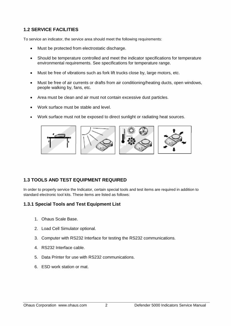
1.2 SERVICE FACILITIES
To service an indicator, the service area should meet the following requirements:
Must be protected from electrostatic discharge.
Should be temperature controlled and meet the indicator specifications for temperature environmental requirements. See specifications for temperature range.
Must be free of vibrations such as fork lift trucks close by, large motors, etc.
Must be free of air currents or drafts from air conditioning/heating ducts, open windows, people walking by, fans, etc.
Area must be clean and air must not contain excessive dust particles.
Work surface must be stable and level.
Work surface must not be exposed to direct sunlight or radiating heat sources.
1.3 TOOLS AND TEST EQUIPMENT REQUIRED
In order to properly service the Indicator, certain special tools and test items are required in addition to
standard electronic tool kits. These items are listed as follows:
1.3.1 Special Tools and Test Equipment List
1. Ohaus Scale Base.
2. Load Cell Simulator optional.
3. Computer with RS232 Interface for testing the RS232 communications.
4. RS232 Interface cable.
5. Data Printer for use with RS232 communications.
6. ESD work station or mat.

Ohaus Corporation www.ohaus.com 3 Defender 5000 Indicators Service Manual
1.3.2 Standard Tools and Test Equipment List
1. Standard Electronics Tool Kit
2. Digital Voltmeter (DVM), with clip on probes. Input impedance of at least 10 megohms in the 1 Volt dc position.
3. Soldering Iron, solder and flux remover.
1.4 OVERVIEW OF PARTS AND CONTROLS
1.4.1 TD52P
TABLE 1-1 TD52P PARTS
Item Description
1 Data Label
2 Front Housing
3 Control Panel
4 Mounting Bracket
5 Screw (4)
6 Adjusting Knob (2)
7 Security Screw
8 Accessory Cover
9 Rear Housing
10 Power Connector
11 RS232 Connector
12 Load Cell Connector
1
2
3
6
9
8
4
5
7
10 11
12
Figure 1-1 TD52P Indicator

Ohaus Corporation www.ohaus.com 4 Defender 5000 Indicators Service Manual
1.4.2 TD52XW TABLE 1-2 TD52XW PARTS
Item Description 1 Control Panel
2 Front Housing
3 Screw (6)
4 Adjusting knob (2)
5 Rear Housing
6 Mounting Bracket
7 Load Cell Connector
8 Strain Relief for Option
9 Power Cord
10 Strain Relief for Option
3
4
5
6
1
2
7 8 9
Figure 1-2 TD52XW Indicator
10
Ohaus Corporation www.ohaus.com 5 Defender 5000 Indicators Service Manual
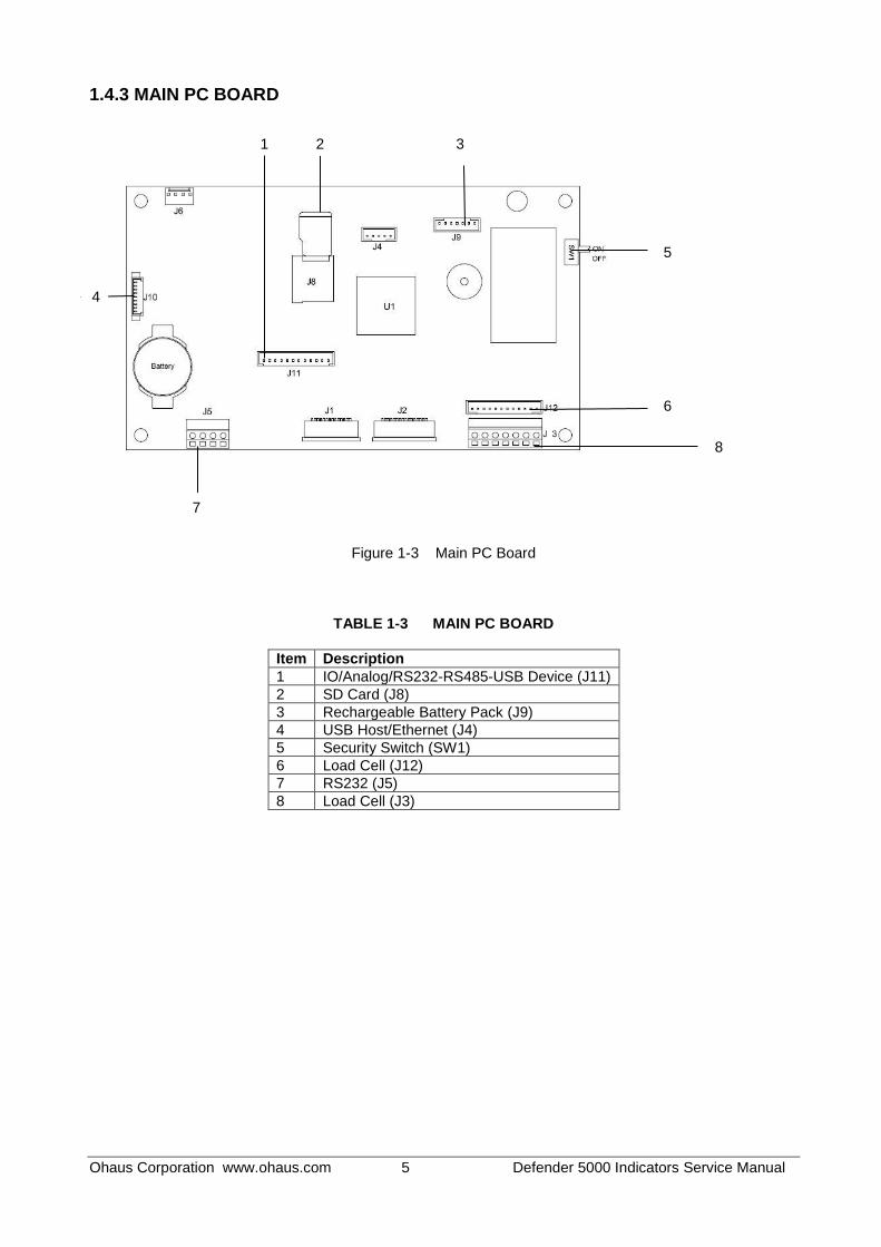
1.4.3 MAIN PC BOARD
Figure 1-3 Main PC Board
TABLE 1-3 MAIN PC BOARD
Item Description
1 IO/Analog/RS232-RS485-USB Device (J11)
2 SD Card (J8)
3 Rechargeable Battery Pack (J9)
4 USB Host/Ethernet (J4)
5 Security Switch (SW1)
6 Load Cell (J12)
7 RS232 (J5)
8 Load Cell (J3)
4
7
2 1 3
5
6
8

Ohaus Corporation www.ohaus.com 6 Defender 5000 Indicators Service Manual
1.5 CONTROL FUNCTIONS
Button Action Short press: If the terminal is Off, power on the terminal; if the terminal is On, clear the
data input. Long press: Power off the terminal.
Short press: Send the current display value to RS232 port in the case where the "Communication -> RS232 setup->Assignment->Demand" is "On". Long press: Change the current weighing unit. Press and hold the key to scroll through the list of enabled units. Release the key to switch to the unit selected.
Short press: Press the key to enter the Library. Long press: Press and hold this key to change weighing modes. Press and hold the key to scroll through all weighing modes. Release the key to switch to the mode selected.
Short press: Press the key to enter user profile. Long press: Press the key to enter user menu.
The soft keys correspond to several icons at the bottom of the display area. These icons indicate configuration, ID input, accumulate, exit, etc. (available in certain circumstances).
To enter ‘2’-‘9’, press the numeric button in the mode of numeric input.
To Enter ‘A’, press 2 times in the mode of uppercase input. To
enter ‘Z’, press 5 times in the mode of lowercase input.
To enter ‘0’, press the button in the mode of numeric input. To enter a space, press the button in the mode of uppercase or lower case input.
To enter '1', press the button in the mode of numeric input. To enter '#' or '/', press the button in the mode of uppercase input. To enter '@', '_' or '&', press the button in the mode of lowercase input.
Switch between three input modes, namely, numeric, lowercase and uppercase input.
To enter '.', press the button in the mode of numeric input. To enter '+' or '-', press the button in he mode of uppercase or lowercase input.
Short press: When the load on the pan is within the zero range, press this key to set the display to zero. Short press: When a tare has been entered and the load on the pan is within the zero range, press this key to clear the tare value and set the display to zero.
Short press: When a container is on the pan, press this key to store the weight of the container as the tare value. Short press: Enter the known weight of a container using the numeric keypad, and then press this key to establish the preset tare value. Short press: When a tare has been entered, empty the pan and press this key to clear the tare value. Long press: If a preset tare has been entered, press this key to view the preset tare value.

Ohaus Corporation www.ohaus.com 7 Defender 5000 Indicators Service Manual
1.6 EXTERNAL CONNECTIONS
This section of the manual explains the external connection of the product.
1.6.1 Scale Base with Connector Ohaus bases with a connector can be attached to the external load cell connector (Figure 1-1, item 12). To make the connection, plug the base connector onto the external load cell connector. Then rotate the base connector’s locking ring clockwise. Refer to section 1.7.2 for bases without a connector.
1.6.2 RS232 interface Cable to TD52P Connect the optional RS232 cable to the RS232 connector (Figure 1-1, item 11).
Pin Connection
1 N/C
2 TXD
3 RXD
4 N/C
5 GND
6 N/C
7 CTS
8 RTS
9 N/C
1.6.3 AC Power to TD52P Connect the AC power cord (supplied) to the power receptacle (Figure 1-1, item 10), then connect the AC plug to an electrical outlet.
1.6.4 AC Power to TD52XW Connect the AC plug to a properly grounded electrical outlet.
1.6.5 Battery Power The indicator can be operated on a rechargeable battery pack (not supplied) when AC power is not available. It will automatically switch to battery operation if there is power failure or the power cord is removed. The indicator can operate for up to 21 hours on battery power. During battery operation, the battery charge symbol indicates the battery status. The indicator will automatically turn-off when the batteries are fully discharged. Find detailed installation information in battery pack (P/N 30424405) operation manual.
1.7 Internal Connections
Some connections require the housing to be opened.
1.7.1 Opening the Housing
CAUTION: ELECTRICAL SHOCK HAZARD. REMOVE ALL POWER CONNECTIONS TO THE INDICATOR BEFORE SERVICING OR MAKING INTERNAL CONNECTIONS. THE HOUSING SHOULD ONLY BE OPENED BY AUTHORIZED AND QUALIFIED PERSONNEL, SUCH AS AN ELECTRICAL TECHNICIAN.
TD52P Remove the four Phillips head screws from the rear housing. Remove the front housing being careful not to disturb the internal connections. Once all connections are made, reattach the front housing.
Figure 1-4 RS232 Pins

Ohaus Corporation www.ohaus.com 8 Defender 5000 Indicators Service Manual
TD52XW Remove the four hex head screws from the rear housing. Open the housing by carefully pulling the front housing forward. Once all connections are made, reattach the front housing. The screws should be tightened to 2.5 N•m (20-25 in-lb) torque to ensure a watertight seal.
1.7.2 Scale Base Without Connector For connecting bases (which do not have the connector) to a TD52P or TD52XW, a cable gland kit (P/N 30379716) is available as an accessory. Removing the pre-installed Load Cell connector and wiring harness Before doing the connections, remove the pre-installed Load Cell connector and wiring harness by following the steps below.
1. Open the housing by carefully pulling the front housing forward. 2. Unplug the white load cell connector from the main PCBA board (red circle). 3. Remove the metal terminal (Figure 1-1, item 12) connector from the rear housing.(green circle)
Installing Cables and Connectors In order to meet certain electrical noise emission limits and to protect the TD52P and TD52XW from external influences, it is necessary to install a ferrite core on the load cell cable connected to the terminal. The ferrite core is included with the terminal. To install the ferrite, simply route the cable through the center of the core and then take one wrap around the outside of the core and route the cable through the center again. Either the complete cable or the individual wires can be wrapped through the ferrite. This should be done as close to the enclosure as possible. See Figure 1-5.
Figure 1-5
Main Board Wiring Connections Once the TD52P and TD52XW enclosure is open, connections can be made to the terminal strips on the main board, as shown in Figure 1-6.

Ohaus Corporation www.ohaus.com 9 Defender 5000 Indicators Service Manual
Figure 1-6
Jumper Connections The TD52P and TD52XW terminals are designed to support both 2mV/V and 3mV/V load cells from the same circuitry. A load cell output rating selection jumper is not required. Figure 1-7 shows the terminal definitions for the analog load cell terminal strip. Note that when using four-wire load cells, jumpers must be placed between the +Excitation and +Sense terminals and between the Excitation and Sense terminals.
Figure 1-7 Jumper Connections
After wiring is completed, replace the indicator housing screws. Make sure the liquid-tight connector is properly tightened.
Ohaus Corporation www.ohaus.com 10 Defender 5000 Indicators Service Manual
1.7.3 RS232 Interface Cable to TD52XW Pass the optional RS232 cable through the strain relief (Figure 1-2, item 10) and attach it to terminal block J5 (Figure 1-3, item 7). Tighten the strain relief to maintain a watertight seal.
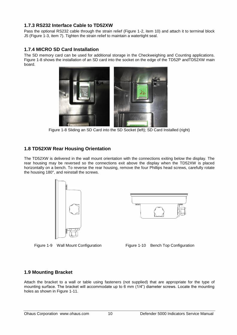
1.7.4 MICRO SD Card Installation The SD memory card can be used for additional storage in the Checkweighing and Counting applications. Figure 1-8 shows the installation of an SD card into the socket on the edge of the TD52P andTD52XW main board.
Figure 1-8 Sliding an SD Card into the SD Socket (left); SD Card Installed (right)
1.8 TD52XW Rear Housing Orientation
The TD52XW is delivered in the wall mount orientation with the connections exiting below the display. The rear housing may be reversed so the connections exit above the display when the TD52XW is placed horizontally on a bench. To reverse the rear housing, remove the four Phillips head screws, carefully rotate the housing 180°, and reinstall the screws.
Figure 1-9 Wall Mount Configuration Figure 1-10 Bench Top Configuration
1.9 Mounting Bracket
Attach the bracket to a wall or table using fasteners (not supplied) that are appropriate for the type of mounting surface. The bracket will accommodate up to 6 mm (1/4”) diameter screws. Locate the mounting holes as shown in Figure 1-11.

Ohaus Corporation www.ohaus.com 11 Defender 5000 Indicators Service Manual
2 SETTINGS This section of the manual explains the Menu Structure of the Indicator.
2.1 Menu Structure
TABLE 2-1 MENU STRUCTURE
Calibration Setup Read Out Application Mode
Zero Capacity Unit Stability Weighing
Span Range Zero Range Counting
Linearity
Capacity & Graduation
>|1|< Capacity Filter Level Check
GEO >|1|<Graduation Auto Zero Track Percent
>|2|< Capacity Auto Dim Dynamic
>|2|<Graduation Brightness Reset
Language Screensaver
Power On Zero Auto Off
Power On Unit Base Auto Off
Key Beep Adjust Contrast
Transaction Counter Reset
Next Transaction
Password
Reset
Unit GMP Communication
Gram(g) Date
Format
RS232/ 2
ndRS232/USB
Device*
Configuration
Baud Rate
Kilogram(kg) Date Parity
Pound(lb) Time
Format
Stop Bit
Ounce(oz) Time Handshake
Pound:Ounce (lb:oz)
Project ID
Alt Print CMD
Tonne(t) Scale ID Alt Tare CMD
Ton(ton) Reset Alt Zero CMD
Custom Unit
Reset
Unit Name
Print Setup Assignment
Figure 1-11 Mounting Bracket Dimensions

Ohaus Corporation www.ohaus.com 12 Defender 5000 Indicators Service Manual
Unit GMP Communication
Factor
Select Template
Exponent
Edit Template
LSD
Edit String
Reset
Reset
RS485*
Configuration
Address
Baud Rate
Parity
Stop Bit
Handshake
Alt Print CMD
Alt Tare CMD
Alt Zero CMD
Reset
Print Setup
Assignment
Select Template
Edit Template
Edit String
Reset
Ethernet*
Configuration
Host Name
MAC Address
Port
Version
DHCP
IP Address
Subnet Mask
Gateway
Primary DNS
Secondary DNS
Alt Print CMD
Alt Tare CMD
Alt Zero CMD
Reset
Print Setup
Assignment
Select Template
Edit Template
Edit String
Reset
Wifi* Configuration
MAC Address
Search
DHCP Client
IP Address
Subnet Mask
Gateway
Port
Alt Print CMD
Alt Tare CMD
Alt Zero CMD
Reset

Ohaus Corporation www.ohaus.com 13 Defender 5000 Indicators Service Manual
Unit GMP Communication
Print Setup
Assignment
Select Template
Edit Template
Edit String
Reset
Bluetooth*
Device name OHBT_1
MAC Address
00-11-22-33-44-55
Search Device
BT Base Info
Device name
MAC Address
LFT
Battery
Analog*
Source
None, Displayed Weight, ABS-Displayed Weight, Gross Weight
Output Type 4-20mA, 0-10V
Zero Value
0(any valid value below the high limit)
Full Scale Value
Desired source value, scale capacity
Cal Output Zero
Cal Output Full
SD Card Maintenance
Library Export Menu
Memory Mode Import Menu
Link to Diagnosis
User Mode Service Menu
User Profiles
* Sub- menu for options will be active only when the specific board is installed.
The Bluetooth® word mark and logos are registered trademarks owned by Bluetooth SIG, Inc. and any use of such marks by OHAUS
is under license.
2.2 Menu Navigation
To enter the Main Menu, press the button from any application home screen.
Ohaus Corporation www.ohaus.com 14 Defender 5000 Indicators Service Manual
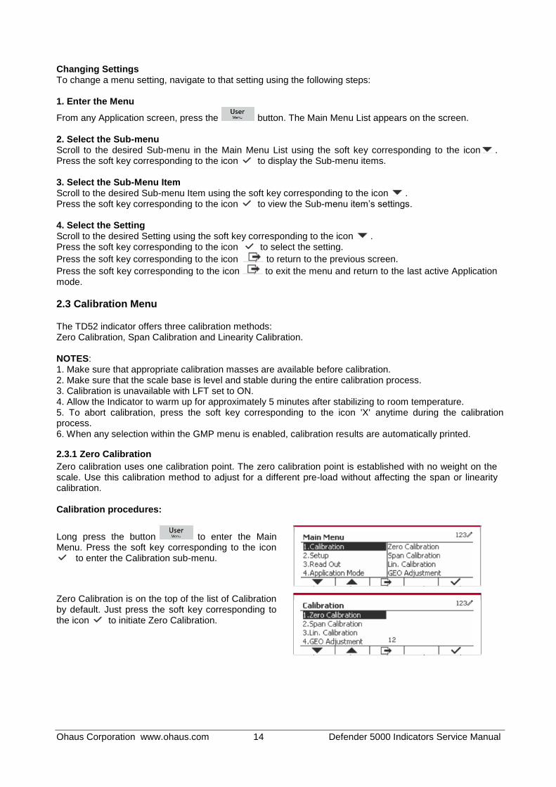
Changing Settings To change a menu setting, navigate to that setting using the following steps: 1. Enter the Menu
From any Application screen, press the button. The Main Menu List appears on the screen. 2. Select the Sub-menu Scroll to the desired Sub-menu in the Main Menu List using the soft key corresponding to the icon . Press the soft key corresponding to the icon to display the Sub-menu items. 3. Select the Sub-Menu Item Scroll to the desired Sub-menu Item using the soft key corresponding to the icon . Press the soft key corresponding to the icon to view the Sub-menu item’s settings.
4. Select the Setting Scroll to the desired Setting using the soft key corresponding to the icon . Press the soft key corresponding to the icon to select the setting.
Press the soft key corresponding to the icon to return to the previous screen.
Press the soft key corresponding to the icon to exit the menu and return to the last active Application mode.
2.3 Calibration Menu
The TD52 indicator offers three calibration methods: Zero Calibration, Span Calibration and Linearity Calibration. NOTES: 1. Make sure that appropriate calibration masses are available before calibration. 2. Make sure that the scale base is level and stable during the entire calibration process. 3. Calibration is unavailable with LFT set to ON. 4. Allow the Indicator to warm up for approximately 5 minutes after stabilizing to room temperature. 5. To abort calibration, press the soft key corresponding to the icon 'X' anytime during the calibration process. 6. When any selection within the GMP menu is enabled, calibration results are automatically printed.
2.3.1 Zero Calibration
Zero calibration uses one calibration point. The zero calibration point is established with no weight on the scale. Use this calibration method to adjust for a different pre-load without affecting the span or linearity calibration. Calibration procedures:
Long press the button to enter the Main Menu. Press the soft key corresponding to the icon
to enter the Calibration sub-menu.
Zero Calibration is on the top of the list of Calibration by default. Just press the soft key corresponding to the icon to initiate Zero Calibration.

Ohaus Corporation www.ohaus.com 15 Defender 5000 Indicators Service Manual
Clear the pan and then press the soft key corresponding to the icon .
The message 'Completed' will be displayed on the screen.
Exit Zero Calibration by pressing the soft key corresponding to the icon . To return to the Main Menu, press the soft key corresponding to the icon .
2.3.2 Span Calibration
Span Calibration uses one point. The span calibration point is established with a calibration mass placed on the scale. Note: Span Calibration should be performed after Zero Calibration. Calibration procedures:
Long press the button to enter the Main Menu.
Press the soft key corresponding to the icon to enter the Calibration sub-menu. Scroll to Span Calibration using the soft key corresponding to the icon .
Press the soft key corresponding to the icon to initiate Span Calibration. Place a calibration mass of the specified weight on the pan and press the soft key corresponding to the icon . To change to a different calibration point, input the value desired, and then place the corresponding weight on the pan for calibration.
A suggestive message shows on the screen.
The message 'Completed' will be displayed on the screen.

Ohaus Corporation www.ohaus.com 16 Defender 5000 Indicators Service Manual
Exit Span Calibration by pressing the soft key corresponding to the icon . To return to the Main Menu, press the soft key
corresponding to the icon . Note: Span Calibration should be performed after Zero Calibration.
2.3.3 Linearity Calibration
Linearity calibration uses 3 calibration points. The full calibration point is established with a weight on the scale. The mid calibration point is established with a weight equal to half of the full calibration weight on the scale. The zero calibration point is established with no weight on the scale. The mid calibration points cannot be altered by the user during the calibration procedure. Calibration procedures:
Long press the button to enter the Main Menu.
Press the soft key corresponding to the icon to enter the Calibration sub-menu. Scroll to Linearity Calibration using the soft key corresponding to the icon .
Press the soft key corresponding to the icon to initiate Linearity Calibration. Clear the pan and press the soft key corresponding to the icon .
Put the calibration mass of the specified weight on the pan, and then press the soft key corresponding to the icon for confirmation. To change to a different calibration point, input the value desired, and then place the corresponding weight on the pan for calibration.
Put the calibration mass on the pan, and then press the soft key corresponding to the icon for confirmation. To change to a different calibration point, input the value desired, and then place the corresponding weight on the pan for calibration.
The message 'Completed' will be displayed on the screen.

Ohaus Corporation www.ohaus.com 17 Defender 5000 Indicators Service Manual
2.3.4 GEO Adjustment
Set the GEO factor that corresponds to your location. GEO codes are numbered 0-31.
Long press the button to enter the Main Menu. Select the menu item Calibration by pressing the soft key corresponding to the icon .
Scroll to GEO Adjustment using the soft key corresponding to the icon .
Press the soft key corresponding to the icon to
edit the GEO value. Press the button and enter the desired value using the alphanumeric keypad. After editing, press the soft key corresponding
to the icon to exit the menu.
Note: See table 4-3 for GEO values.
2.4 Setup Menu
When the Indicator connects to a scale base for the first time, enter this menu to set the Capacity Unit, Range, Capacity and Graduation. Default settings are bold.
Setup Options
Capacity Unit g, kg, t, lb, ton
Range Single, Dual
>|1|< Capacity 1-999999
>|1|< Graduation 0.0001~100
>|2|< Capacity 1-999999
>|2|< Graduation 0.0001~100
Language English, French, German, Italian, Spanish,
Chinese, Japanese, Korean, Russian, Polish
Exit Linearity Calibration by pressing the soft key corresponding to the icon . To return to the Main Menu, press the soft key
corresponding to the icon .
Ohaus Corporation www.ohaus.com 18 Defender 5000 Indicators Service Manual
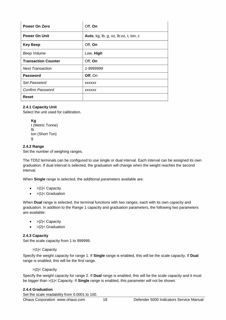
Power On Zero Off, On
Power On Unit Auto, kg, lb, g, oz, lb:oz, t, ton, c
Key Beep Off, On
Beep Volume Low, High
Transaction Counter Off, On
Next Transaction 1-9999999
Password Off, On
Set Password xxxxxx
Confirm Password xxxxxx
Reset
2.4.1 Capacity Unit
Select the unit used for calibration.
Kg t (Metric Tonne) lb ton (Short Ton) g
2.4.2 Range
Set the number of weighing ranges. The TD52 terminals can be configured to use single or dual interval. Each interval can be assigned its own
graduation. If dual interval is selected, the graduation will change when the weight reaches the second
interval.
When Single range is selected, the additional parameters available are:
>|1|< Capacity
>|1|< Graduation
When Dual range is selected, the terminal functions with two ranges, each with its own capacity and
graduation. In addition to the Range 1 capacity and graduation parameters, the following two parameters
are available:
>|2|< Capacity
>|2|< Graduation
2.4.3 Capacity
Set the scale capacity from 1 to 999999.
>|1|< Capacity
Specify the weight capacity for range 1. If Single range is enabled, this will be the scale capacity. If Dual
range is enabled, this will be the first range.
>|2|< Capacity
Specify the weight capacity for range 2. If Dual range is enabled, this will be the scale capacity and it must
be bigger than >|1|< Capacity. If Single range is enabled, this parameter will not be shown.
2.4.4 Graduation
Set the scale readability from 0.0001 to 100.

Ohaus Corporation www.ohaus.com 19 Defender 5000 Indicators Service Manual
>|1|<Graduation Specify the graduation for weighing range 1. If Single range is enabled, this will be the graduation for the
entire weighing range of the scale. If Dual range is enabled, this will be the graduation used in the lower
range.
>|2|<Graduation Specify the graduation for range 2. If Dual range is enabled, this will be the graduation for the second
weighing range of the scale. If Single range is enabled, this parameter will not be shown.
NOTE: Graduation settings are limited to values from Capacity divided by 600 to Capacity divided by 75000. Therefore, not all settings are available for each capacity.
2.4.5 Language
Set the language displayed for menus and displayed messages. English Deutsch Français Italiano Polski
Spanish
한국
中文
日本语
2.4.6 Power On Zero
Zero the balance at Power On. Off = disabled. On = enabled.
2.4.7 Power On Unit
Set the unit that will be displayed at Power On.
Automatic g kg lb oz lb:oz t (Metric Tonne) ton (Short Ton)
2.4.8 Key Beep
Set how the beeper sounds when a key is pressed. Off = no sound On = sound
2.4.9 Transaction Counter
The transaction counter is a seven-digit counter that tracks the total transactions. When the value reaches 9,999,999, the next transaction causes a roll-over to 0000001. Off = the transaction counter will not increase. On = the transaction counter will increase with the additional menu item Next Transaction available.

Ohaus Corporation www.ohaus.com 20 Defender 5000 Indicators Service Manual
2.4.9.1 Next Transaction
The value of the next transaction displays in the Next Transaction field.
2.4.10 Password
Set the password. Off = the menu is accessed freely without password. On = the menu is accessed only after entering a password up to 6 digits.
2.4.11 Reset
Reset the Setup menu to the factory defaults (except Range, Capacity and Graduation). No = not reset. Yes = reset. NOTE: If the Security Switch is set to ON, the Capacity Unit, Range, Capacity, Graduation and Power On Zero settings are not reset.
2.5 Readout Menu
Enter this menu to customize display functionality. Default settings are bold.
Read Out Options
Stability 0.5d, 1d, 2d, 5d
Zero Range +/-2%, +/-100%
Filter Level Low, Medium, High
Auto Zero Track Off, 0.5d, 1d, 3d
Backlight Off, 1min, 2min, 5min,10min, Always On
Screensaver Off, 5min, 10min, 30min
Auto Off Off, 5min, 10min, 30min
Base Auto Off Off, 5min, 10min, 30min
Adjust Contrast 1, 2, 3, 4, 5
Reset
2.5.1 Stability
Set the amount the reading can vary before the stability symbol turns off. 0.5d = 0.5 scale division 1d = 1 scale division 2d = 2 scale divisions 5d = 5 scale divisions
2.5.2 Zero Range
Set the percentage of scale capacity that may be zeroed.
2% 100%
NOTE: The setting is forced and locked to 2% when the Security Switch is set to the locked position.
2.5.3 Filter Level
Set the amount of signal filtering.
Low = faster stabilization time with less stability.

Ohaus Corporation www.ohaus.com 21 Defender 5000 Indicators Service Manual
Medium = normal stabilization time with normal stability. High = slower stabilization time with more stability.
2.5.4 Auto Zero Tracking
Set the automatic zero tracking functionality.
OFF = disabled. 0.5division = the display will maintain zero until a change of 0.5 division per second has been
exceeded. 1d = the display will maintain zero until a change of 1 division per second has been
exceeded. 3d = the display will maintain zero until a change of 3 divisions per second has been
exceeded.
2.5.5 Auto Dim
Set the display backlight functionality. Settings: 1 min = backlight turns off after 1 minute of no activity. 2 min = backlight turns off after 2 minute of no activity. 5 min = backlight turns off after 5 minute of no activity. 10 min = backlight turns off after 10 minute of no activity. Always on Off
2.5.6 ScreenSaver
Set whether the screensaver is enabled after the selected time period. Off = Disabled. 5 min = the screensaver is enabled after 5 minutes. 10 min = the screensaver is enabled after 10 minutes. 30 min = the screensaver is enabled after 30 minutes.
2.5.7 Auto Off
Set whether the display enters sleep mode after the selected time period. Off = Disabled. 5 min = the display enters sleep mode after 5 minutes. 10 min = the display enters sleep mode after 10 minutes. 30 min = the display enters sleep mode after 30 minutes.
2.5.8 Adjust Contrast
Set the contrast degree of the display. 1 2 3 4 5
2.5.9 Reset
Reset all settings to factory default settings. Yes = Reset. No = Do not reset. NOTE: If the Security Switch is set to ON, Stability, Zero Range, Filter Level and Auto Zero Track settings are not reset.

Ohaus Corporation www.ohaus.com 22 Defender 5000 Indicators Service Manual
2.6 Discrete I/O
Long press the button to enter the Main Menu. Select Application Mode by pressing the soft key corresponding to the icon .
Press the soft key corresponding to the icon to enter the sub-menu Application Mode.
Enable The current selected application mode can't be set Off. Discrete I/O setup menus allow the configuration of 2 inputs and 4 outputs depending on different application mode. Reset If Reset is selected and confirmed, all the submenu value will be set to default. For more details, see the table below.
Application Mode & Discrete I/O
Options (bold is default)
Weighing
Enable On, Off
Discrete Input1 Off, Zero, Tare, Clear Tare, Print, Unit, Accumulate
Discrete Input2 Off, Zero, Tare, Clear Tare, Print, Unit, Accumulate
Discrete Output1 Off, Overload, Underload, Zero
Discrete Output2 Off, Overload, Underload, Zero
Discrete Output3 Off, Overload, Underload, Zero
Discrete Output4 Off, Overload, Underload, Zero
Counting
Enable On, Off
Discrete Input1 Off, Zero, Tare, Clear Tare, Print, Unit, Accumulate
Discrete Input2 Off, Zero, Tare, Clear Tare, Print, Unit, Accumulate
Discrete Output1 Off, Overload, Underload, Zero
Discrete Output2 Off, Overload, Underload, Zero
Discrete Output3 Off, Overload, Underload, Zero
Discrete Output4 Off, Overload, Underload, Zero
Check
Enable On, Off
Discrete Input1 Off, Zero, Tare, Clear Tare, Print, Unit, Accumulate
Discrete Input2 Off, Zero, Tare, Clear Tare, Print, Unit, Accumulate
Discrete Output1 Off, Under, Over, Accept, Under/Over, Overload, Underload, Zero
Discrete Output2 Off, Under, Over, Accept, Under/Over, Overload, Underload, Zero
Discrete Output3 Off, Under, Over, Accept, Under/Over, Overload, Underload, Zero
Discrete Output4 Off, Under, Over, Accept, Under/Over, Overload, Underload, Zero
Percent Enable On, Off
Dynamic
Enable On, Off
Discrete Input1 Off, Zero, Tare, Clear Tare, Print, Start, Reset
Discrete Input2 Off, Zero, Tare, Clear Tare, Print, Start, Reset

Ohaus Corporation www.ohaus.com 23 Defender 5000 Indicators Service Manual
Application Mode & Discrete I/O
Options (bold is default)
Discrete Output1 Off, Overload, Underload, Zero
Discrete Output2 Off, Overload, Underload, Zero
Discrete Output3 Off, Overload, Underload, Zero
Discrete Output4 Off, Overload, Underload, Zero
Reset
2.7 Weighing Unit
Enter this menu to activate the desired units. Default settings are bold. NOTE: Due to national laws, the indicator may not include some of the units of measure listed. If the Security Switch is set to ON, the Units are locked at their current setting.
2.7.1 Gram (g)
Set the status. Off = Disabled On = Enabled
2.7.2 Kilogram (kg)
Set the status. Off = Disabled On = Enabled
2.7.3 Pound (lb)
Set the status. Off = Disabled On = Enabled
2.7.4 Ounce (oz)
Set the status. Off = Disabled On = Enabled
2.7.5 Pound: Ounce (lb: oz)
Set the status. Off = Disabled On = Enabled
2.7.6 Tonne (t)
Set the status. Off = Disabled On = Enabled
2.7.7 Ton (ton)
Set the status. Off = Disabled On = Enabled

Ohaus Corporation www.ohaus.com 24 Defender 5000 Indicators Service Manual
2.7.8 Custom Unit (c)
Use the Custom Unit to display weight in an alternative unit of measure. The custom unit is defined using a conversion factor, where the conversion factor is the number of custom units per gram expressed in scientific notation (Factor x 10^Exponent).
Factor Set the conversion factor using the numeric keypad.
Settings of 0.1000000 to 1.9999999 are available. The default setting is 1.0.
Exponent Set the factor multiplier. -3 = divide the Factor by 1000 (1x10
-3)
-2 = divide the Factor by 100 (1x10⁻²
) -1 = divide the Factor by 10 (1x10
-1)
0 = multiply the Factor by 1 (1x100)
1 = multiply the Factor by 10 (1x101)
2 = multiply the Factor by 100 (1x10²)
Least Significant Digit(LSD) Set the graduation. Settings of 0.5, 1, 2, 5, 10, 100 are available. The Custom Unit’s name can be customized up to 3 characters. Note: Custom Unit is locked at Off position when the Security Switch is set to the locked position. Custom Unit is not available when Range is set to Dual interval. Set the status. Off = Disabled On = Enabled
2.8 GMP Menu
Enter this menu to set the Good Manufacturing Practice (GMP) data.
2.8.1 Date Format
Set the date format. MM/DD/YYYY = Month.Day.Year DD/MM/YYYY = Day.Month.Year YYYY/MM/DD = Year.Month.Day
2.8.2 Date
Set the date. 00 to 9999 = year position 01 to 12 = month position 01 to 31 = day position Refer to Section 3.2 Menu Navigation to enter settings.
2.8.3 Time Format
Set the time format. 24 hr = 24 hour format. 12 hr = 12 hour format.
Ohaus Corporation www.ohaus.com 25 Defender 5000 Indicators Service Manual
2.8.4 Time
Set the time. 24 hour format 00 to 23 = hour position 00 to 59 = minute position
2.8.5 Project ID
Set the Project identification. Refer to Section 3.2 Menu Navigation to enter settings.
2.8.6 Scale ID
Set the Project identification. Refer to Section 3.2 Menu Navigation to enter settings.
2.8.7 Reset
If Reset is selected and confirmed, all the submenu value will be set to default.
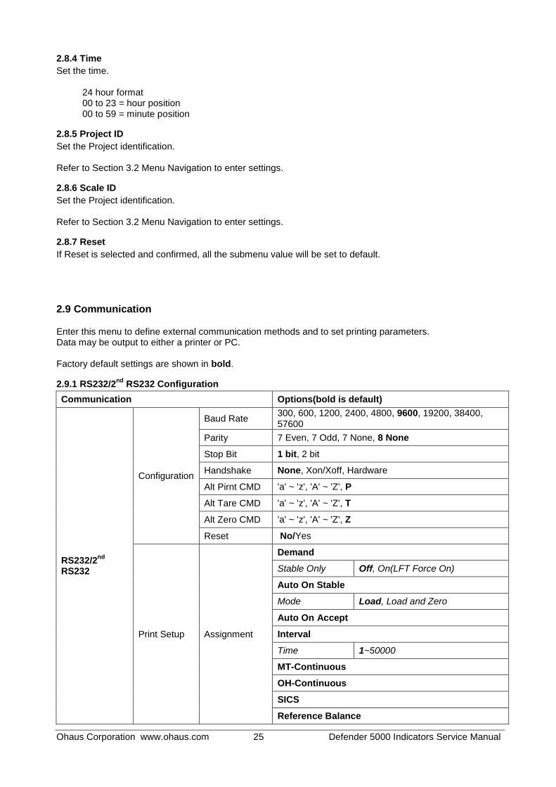
2.9 Communication
Enter this menu to define external communication methods and to set printing parameters. Data may be output to either a printer or PC. Factory default settings are shown in bold.
2.9.1 RS232/2nd
RS232 Configuration
Communication Options(bold is default)
RS232/2nd
RS232
Configuration
Baud Rate 300, 600, 1200, 2400, 4800, 9600, 19200, 38400, 57600
Parity 7 Even, 7 Odd, 7 None, 8 None
Stop Bit 1 bit, 2 bit
Handshake None, Xon/Xoff, Hardware
Alt Pirnt CMD 'a' ~ 'z', 'A' ~ 'Z', P
Alt Tare CMD 'a' ~ 'z', 'A' ~ 'Z', T
Alt Zero CMD 'a' ~ 'z', 'A' ~ 'Z', Z
Reset No/Yes
Print Setup Assignment
Demand
Stable Only Off, On(LFT Force On)
Auto On Stable
Mode Load, Load and Zero
Auto On Accept
Interval
Time 1~50000
MT-Continuous
OH-Continuous
SICS
Reference Balance
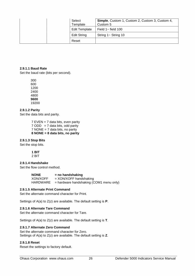
Ohaus Corporation www.ohaus.com 26 Defender 5000 Indicators Service Manual
Select Template
Simple, Custom 1, Custom 2, Custom 3, Custom 4, Custom 5
Edit Template Field 1~ field 100
Edit String String 1~ String 10
Reset
2.9.1.1 Baud Rate
Set the baud rate (bits per second). 300 600 1200 2400 4800 9600 19200
2.9.1.2 Parity
Set the data bits and parity.
7 EVEN = 7 data bits, even parity 7 ODD = 7 data bits, odd parity 7 NONE = 7 data bits, no parity 8 NONE = 8 data bits, no parity
2.9.1.3 Stop Bits
Set the stop bits.
1 BIT 2 BIT
2.9.1.4 Handshake
Set the flow control method.
NONE = no handshaking XON/XOFF = XON/XOFF handshaking HARDWARE = hardware handshaking (COM1 menu only)
2.9.1.5 Alternate Print Command
Set the alternate command character for Print. Settings of A(a) to Z(z) are available. The default setting is P.
2.9.1.6 Alternate Tare Command
Set the alternate command character for Tare. Settings of A(a) to Z(z) are available. The default setting is T.
2.9.1.7 Alternate Zero Command
Set the alternate command character for Zero. Settings of A(a) to Z(z) are available. The default setting is Z.
2.9.1.8 Reset
Reset the settings to factory default.

Ohaus Corporation www.ohaus.com 27 Defender 5000 Indicators Service Manual
2.9.2 Print Setup of RS232/2nd RS232
2.9.2.1 Demand
If Demand is selected, the sub-menu Stable Only will display. Set the printing criteria.
OFF = values are printed immediately, regardless of stability. ON = values are printed only when the stability criteria are met.
Note: For more detailed information, please refer to Section 5.3 Printout.
2.9.2.2 Auto On Stable
If Auto On Stable is selected, the sub-menu Mode will display. Set the printing mode. Load = Prints when the displayed load is stable. Load and Zero = Prints when the displayed load and zero reading is stable.
2.9.2.3 Auto On Accept
If Auto On Accept is selected and the weighing mode is Check, values will be printed when the weight is accepted. ACCEPT = printing occurs each time the display is within the Checkweigh accept
range and stability criteria are met.
2.9.2.4 Interval
If Interval is selected, the sub-menu Time will display.
INTERVAL = printing occurs at the defined time interval. The time interval can be set through the numeric keypad. Settings of 1 to 3600 seconds are available. Default is 0. Printing occurs at the defined time interval.
2.9.2.5 MT-Continuous
If MT-Continuous is selected, the print output will be in the MT-Continuous format.
CONTINUOUS = printing occurs continuously. Note: Refer to Appendix A for MT-Continuous format.
2.9.2.6 OH-Continuous
If OH-Continuous is selected, the print output will be in the OH-Continuous format. Note: Refer to Section 5.1 for OH-Continuous format.
CONTINUOUS = printing occurs continuously.
2.9.2.7 SICS
OFF = disable MT-SICS command ON = enable MT-SICS command Note: Refer to Appendix B for SICS commands.
2.9.2.8 Reference Balance
OFF = do not connect to reference balance ON = connect to reference balance Note: Use a reference balance to perform sampling with a high resolution balance in Counting Mode. Please make sure the balance is already switched on before connected to the new Defender 5000.
Ohaus Corporation www.ohaus.com 28 Defender 5000 Indicators Service Manual
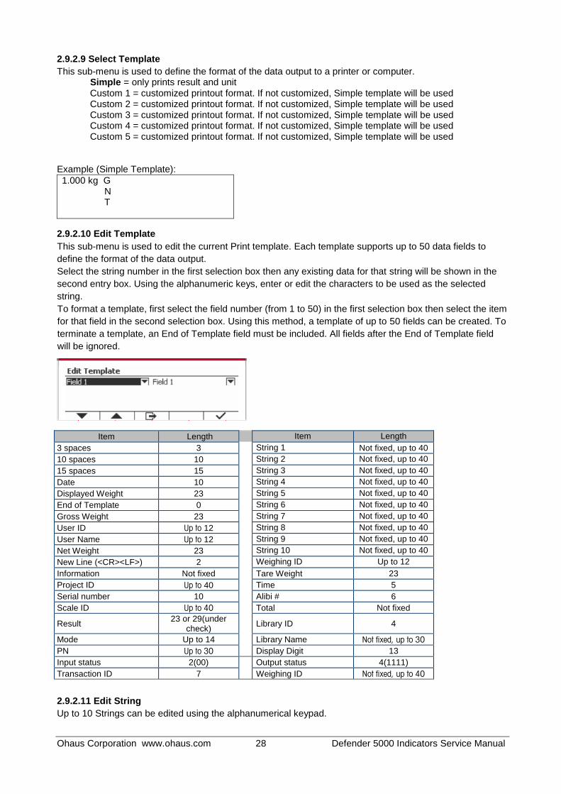
2.9.2.9 Select Template
This sub-menu is used to define the format of the data output to a printer or computer. Simple = only prints result and unit Custom 1 = customized printout format. If not customized, Simple template will be used Custom 2 = customized printout format. If not customized, Simple template will be used Custom 3 = customized printout format. If not customized, Simple template will be used
Custom 4 = customized printout format. If not customized, Simple template will be used Custom 5 = customized printout format. If not customized, Simple template will be used
Example (Simple Template):
1.000 kg G N T
2.9.2.10 Edit Template
This sub-menu is used to edit the current Print template. Each template supports up to 50 data fields to
define the format of the data output.
Select the string number in the first selection box then any existing data for that string will be shown in the
second entry box. Using the alphanumeric keys, enter or edit the characters to be used as the selected
string.
To format a template, first select the field number (from 1 to 50) in the first selection box then select the item
for that field in the second selection box. Using this method, a template of up to 50 fields can be created. To
terminate a template, an End of Template field must be included. All fields after the End of Template field
will be ignored.
Item Length Item Length
3 spaces 3 String 1 Not fixed, up to 40
10 spaces 10 String 2 Not fixed, up to 40
15 spaces 15 String 3 Not fixed, up to 40
Date 10 String 4 Not fixed, up to 40
Displayed Weight 23 String 5 Not fixed, up to 40
End of Template 0 String 6 Not fixed, up to 40
Gross Weight 23 String 7 Not fixed, up to 40
User ID Up to 12 String 8 Not fixed, up to 40
User Name Up to 12 String 9 Not fixed, up to 40
Net Weight 23 String 10 Not fixed, up to 40
New Line (<CR><LF>) 2 Weighing ID Up to 12
Information Not fixed Tare Weight 23
Project ID Up to 40 Time 5
Serial number 10 Alibi # 6
Scale ID Up to 40 Total Not fixed
Result 23 or 29(under
check)
Library ID 4
Mode Up to 14 Library Name Not fixed, up to 30
PN Up to 30 Display Digit 13
Input status 2(00) Output status 4(1111)
Transaction ID 7 Weighing ID Not fixed, up to 40
2.9.2.11 Edit String
Up to 10 Strings can be edited using the alphanumerical keypad.

Ohaus Corporation www.ohaus.com 29 Defender 5000 Indicators Service Manual
Select the string number in the first selection box then any existing data for that string will be shown in the second entry box. Using the alphanumeric keys, enter or edit the characters to be used as the selected string.
String 1 = OHAUS (Default) String 2 = T52 (Default)
2.9.2.12 Reset
Reset the settings to factory default.
2.9.3 RS485 Configuration
Please refer to RS485 Configuration in the Defender® 5000 RS232/RS485/USB Interface Instruction
Manual.
2.9.4 Ethernet Configuration
Please refer to Configuration in the Defender® 5000 Ethernet Interface Instruction Manual.
2.9.5 Wifi Configuration
Please refer to Wifi Configuration in the Defender® 5000 USB Host Instruction Manual.
2.9.6 Bluetooth Configuration
Please refer to Bluetooth Configuration in the Defender® 5000 USB Host Instruction Manual.
2.9.7 Analog
Please refer to Analog Configuration in the Defender® 5000 Analog Kit Instruction Manual.
2.10 Service Menu
Enter this menu to check the loadcell, software update and factory reset etc., the password (64852) is a must for this operation.
2.10.1 RAMP
The ramp display shows the percentage of use of the A to D circuit, that is, of the temperature-compensated duty cycle. The actual value is not as important as how it changes. It should increase as the weight on the balance is increased. The ramp display should remain constant without fluctuations. The normal range is within 3% to 97%. If the readings are outside this range the load-cell is likely bad. Fluctuations in the display may indicate a mechanical interference, a cable connection problem, a damaged Main PCB or a damaged load-cell.
2.10.2 Expand

Ohaus Corporation www.ohaus.com 30 Defender 5000 Indicators Service Manual
Expand reading is the internal calculation result, which should be up and down following with the Ramp changes.
2.10.3 Firmware Update
Please refer to "APPENDIX C. Software Update via Micro SD card" for the software update.
2.10.4 Factory Reset
Reset the indicator the initial setup.
2.10.5 Board Info
Scroll down the menu to the Board Info, enter this Menu you will find the software version and the PCB series number
3 MAINTENANCE
CAUTION: DISCONNECT THE UNIT FROM THE POWER SUPPLY BEFORE CLEANING.
3.1 Model T52P Cleaning
The housing may be cleaned with a cloth dampened with a mild detergent if necessary.
Do not use solvents, chemicals, alcohol, ammonia or abrasives to clean the housing or control panel.
3.2 Model TD52XW Cleaning
Use approved cleaning solutions for the stainless-steel Indicator housing and rinse with water. Dry thoroughly.
Do not use solvents, chemicals, alcohol, ammonia or abrasives to clean the control panel.

Ohaus Corporation www.ohaus.com 31 Defender 5000 Indicators Service Manual
3.3 Troubleshooting
TABLE 8-1 TROUBLESHOOTING
SYMPTOM PROBABLE CAUSE (s) REMEDY
EEP Error EEPROM Checksum Error Corrupted EEPROM data
Unit will not turn on. Power cord not plugged in or properly connected. Power outlet not supplying electricity. Battery discharged (T52P). Other failure.
Check power cord connections. Make sure power cord is plugged in properly into the power outlet. Check power source. Replace batteries (T52P). Service required.
Cannot zero the Scale, or will not zero when turned on.
Load on Scale exceeds allowable limits. Load on Scale is not stable. Load Cell damage.
Remove load on Scale. Wait for load to become stable. Service required.
Unable to calibrate. Lock Calibration Menu set to On. LFT menu set to On. Incorrect value for calibration mass.
Set Lock Calibration Menu to Off. Refer to Section 3.12 Menu Lock. Set LFT menu to Off. Use correct calibration mass.
Cannot display weight in desired weighing unit.
Unit not set to On. Enable unit in the Units Menu. Refer to Section 3.7 in the Unit Menu.
Cannot change menu settings. Menu has been locked. Set selected menu to Off in the Lock Menu. Lockout Switch on the circuit board may need to be set to the Off position.
Error 8.1 Weight reading exceeds Power On Zero limit.
Remove load from scale. Recalibrate scale.
Error 8.2 Weight reading below Power On Zero limit.
Add load to scale. Recalibrate scale.
Error 8.3 Weight reading exceeds Overload limit.
Reduce load on scale.
Error 8.4 Weight reading below Underload limit.
Add load to scale. Recalibrate scale.
Error 8.6 Weight exceeds six digits. Display overflow.
Reduce load on scale.
Error 9.5 Calibration data not present. Calibrate scale.
Battery symbol flashing Batteries are discharged. Replace batteries (T52P).
CAL E Calibration value outside allowable limits
Use correct calibration weight.
NO.SW Attempting to exit the menu with the LFT setting ON and the security switch OFF.
Refer to Section 6.1. Set the security switch to the ON position.
REF WT Err Reference Weight too small. The weight on the platform is too small to define a valid reference weight.
Use a greater weight for sample.
3.4 Service Information
If the troubleshooting section does not resolve your problem, contact an authorized Ohaus Service Agent. For Service assistance in the United States, call toll-free 1-800-526-0659 between 8:00 AM and 5:00 PM Eastern Standard Time. An Ohaus Product Service Specialist will be available to assist you. Outside the USA, please visit our website www.ohaus.com to locate the Ohaus office nearest you.

Ohaus Corporation www.ohaus.com 32 Defender 5000 Indicators Service Manual
4 TECHNICAL DATA
4.1 Specifications
Materials TD52XW Housing: stainless-steel TD52P Housing: ABS plastic Display window: polycarbonate Keypad: polyester
Ambient conditions The technical data is valid under the following ambient conditions: Ambient temperature: -10°C to 40°C / 14°F to 104°F Relative humidity: Maximum relative humidity 80% for temperatures up to 31°C decreasing linearly to 50% relative humidity at 40°C. Altitude: up to 2000m Operability is assured at ambient temperatures between -10°C and 40°C.
TABLE 4-1 SPECIFICATIONS
Indicator Model TD52P TD52XW
Maximum displayed resolution 1:75,000
Maximum approved resolution 1:10,000
Maximum counting resolution 1:1,500,000
Weighing units Kilogram, Gram, Pound, Ounce, Pound: Ounce, Tonne (Metric Tonne), Ton
(Short Ton), Custom
Weighing modes Basic weighing, Percent weighing, Piece Counting with Optimized APW, Animal
weighing/Dynamic weighing, Check weighing
Display Dot matrix LCD
Backlight White
Controls 23 button membrane switch
Ingress protection --- IP68
Load cell excitation voltage 5 VDC
Load cell drive Up to 8 x 350 ohm load cells
Load cell input sensitivity Up to 3 mV/V
Stabilization time Within 2 seconds
Auto zero tracking Off, 0.5 d, 1 d or 3 d
Zeroing range 2% or 100% of capacity
Span calibration 1 kg or 1 lb to capacity
Housing dimensions (W x D x H)
320 X260 X80 mm
12.6 x 10.2 x 3.1 inch
Net weight 1.5 kg 2 kg
3.3 lb 4.4 lb
Shipping weight 2 kg 2.5 kg
4.4 lb 5.5 lb
Operating temperature range -10 °C to 40 °C
14 °F to 104 °F
Mains power 100-240 VAC / 50-60 Hz internal power supply
Overvoltage category II I
Pollution degree 2
Battery power Rechargeable battery pack (option)
Interfaces RS232 (standard)

Ohaus Corporation www.ohaus.com 33 Defender 5000 Indicators Service Manual
4.2 Accessories and Options
TABLE 4-2 OPTIONS
P/N Description
30412537 Interface, WiFi/BT Dongle, OHAUS
30424403 Interface, Analog output
30424404 Interface, RS232/RS485/USB
30424405 Rechargeable Li-ion Battery Kit
30424406 Interface, USB Host
30424021 Light Tower Kit, 3 Colors, OHAUS
30424022 In-use-cover Kit, TD52P
30424023 In-use-cover Kit, TD52XW
30424026 Wall Mount Kit, SST
30424027 Wall Mount Kit, CS
30424409 Extension cable, 9m, TD52
30379716 Cable Gland Kit, M16
30303533 Micro SD Card, 8 G
30097591 Discrete I/O Kit, 2-In/4-Out
30429666 Ethernet Kit
The Rechargeable Battery Kit, RS232 Kit, RS422/485 Kit, Discrete I/O Kit and Analog Output Kit
must be installed by a qualified technician.
Ohaus Corporation www.ohaus.com 34 Defender 5000 Indicators Service Manual
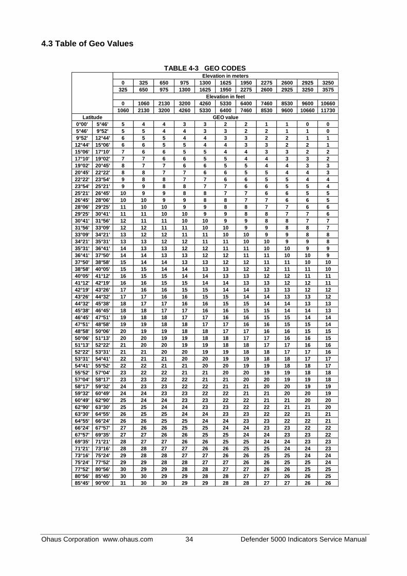
4.3 Table of Geo Values
TABLE 4-3 GEO CODES
0 325 650 975 1300 1625 1950 2275 2600 2925 3250
325 650 975 1300 1625 1950 2275 2600 2925 3250 3575
0 1060 2130 3200 4260 5330 6400 7460 8530 9600 10660
1060 2130 3200 4260 5330 6400 7460 8530 9600 10660 11730
0°00' 5°46' 5 4 4 3 3 2 2 1 1 0 0
5°46' 9°52' 5 5 4 4 3 3 2 2 1 1 0
9°52' 12°44' 6 5 5 4 4 3 3 2 2 1 1
12°44' 15°06' 6 6 5 5 4 4 3 3 2 2 1
15°06' 17°10' 7 6 6 5 5 4 4 3 3 2 2
17°10' 19°02' 7 7 6 6 5 5 4 4 3 3 2
19°02' 20°45' 8 7 7 6 6 5 5 4 4 3 3
20°45' 22°22' 8 8 7 7 6 6 5 5 4 4 3
22°22' 23°54' 9 8 8 7 7 6 6 5 5 4 4
23°54' 25°21' 9 9 8 8 7 7 6 6 5 5 4
25°21' 26°45' 10 9 9 8 8 7 7 6 6 5 5
26°45' 28°06' 10 10 9 9 8 8 7 7 6 6 5
28°06' 29°25' 11 10 10 9 9 8 8 7 7 6 6
29°25' 30°41' 11 11 10 10 9 9 8 8 7 7 6
30°41' 31°56' 12 11 11 10 10 9 9 8 8 7 7
31°56' 33°09' 12 12 11 11 10 10 9 9 8 8 7
33°09' 34°21' 13 12 12 11 11 10 10 9 9 8 8
34°21' 35°31' 13 13 12 12 11 11 10 10 9 9 8
35°31' 36°41' 14 13 13 12 12 11 11 10 10 9 9
36°41' 37°50' 14 14 13 13 12 12 11 11 10 10 9
37°50' 38°58' 15 14 14 13 13 12 12 11 11 10 10
38°58' 40°05' 15 15 14 14 13 13 12 12 11 11 10
40°05' 41°12' 16 15 15 14 14 13 13 12 12 11 11
41°12' 42°19' 16 16 15 15 14 14 13 13 12 12 11
42°19' 43°26' 17 16 16 15 15 14 14 13 13 12 12
43°26' 44°32' 17 17 16 16 15 15 14 14 13 13 12
44°32' 45°38' 18 17 17 16 16 15 15 14 14 13 13
45°38' 46°45' 18 18 17 17 16 16 15 15 14 14 13
46°45' 47°51' 19 18 18 17 17 16 16 15 15 14 14
47°51' 48°58' 19 19 18 18 17 17 16 16 15 15 14
48°58' 50°06' 20 19 19 18 18 17 17 16 16 15 15
50°06' 51°13' 20 20 19 19 18 18 17 17 16 16 15
51°13' 52°22' 21 20 20 19 19 18 18 17 17 16 16
52°22' 53°31' 21 21 20 20 19 19 18 18 17 17 16
53°31' 54°41' 22 21 21 20 20 19 19 18 18 17 17
54°41' 55°52' 22 22 21 21 20 20 19 19 18 18 17
55°52' 57°04' 23 22 22 21 21 20 20 19 19 18 18
57°04' 58°17' 23 23 22 22 21 21 20 20 19 19 18
58°17' 59°32' 24 23 23 22 22 21 21 20 20 19 19
59°32' 60°49' 24 24 23 23 22 22 21 21 20 20 19
60°49' 62°90' 25 24 24 23 23 22 22 21 21 20 20
62°90' 63°30' 25 25 24 24 23 23 22 22 21 21 20
63°30' 64°55' 26 25 25 24 24 23 23 22 22 21 21
64°55' 66°24' 26 26 25 25 24 24 23 23 22 22 21
66°24' 67°57' 27 26 26 25 25 24 24 23 23 22 22
67°57' 69°35' 27 27 26 26 25 25 24 24 23 23 22
69°35' 71°21' 28 27 27 26 26 25 25 24 24 23 23
71°21' 73°16' 28 28 27 27 26 26 25 25 24 24 23
73°16' 75°24' 29 28 28 27 27 26 26 25 25 24 24
75°24' 77°52' 29 29 28 28 27 27 26 26 25 25 24
77°52' 80°56' 30 29 29 28 28 27 27 26 26 25 25
80°56' 85°45' 30 30 29 29 28 28 27 27 26 26 25
85°45' 90°00' 31 30 30 29 29 28 28 27 27 26 26
Elevation in meters
Elevation in feet
GEO valueLatitude

Ohaus Corporation www.ohaus.com 35 Defender 5000 Indicators Service Manual
5 REPLACING MAJOR COMPONENTS (INDICATOR) Ohaus Indicators are precision instruments and should be carefully handled, stored in a clean, dry, dust-free
area, and cleaned periodically. Follow these precautionary steps:
– When an Indicator has had chemicals or liquids spilled on it, all exterior surfaces should be cleaned as soon as possible with warm water on a damp cloth.
– Allow at least 10 minutes for the Indicator to stabilize after moving it from an area which is at a different temperature than the area where it is to be operated.
5.1 Printed Circuit Board (PCB) Replacement
Repairs are not recommended on the PCB. Replacement is recommended rather than repairing.
Replace the PCB for any of the following reasons:
– Display is defective; characters missing or partial display.
– Indicator fails to calibrate properly.
– Display is erratic or unstable.
– Certain functions are not operational.
– Indicator does not operate at all.
5.1.1 TD52P
1. Unplug the Indicator from the AC power source.
2. * If the indicator comes with the optional RS232 kit kindly remove from the bottom housing via removing 2 screws and the cable to the PCBA.
3. Remove the four screws from the Bottom Housing and U bracket.
WARNING: Electric Shock Hazard. Disconnect the Indicator from power before
servicing.
CAUSION: Observe precautions for handling electrostatic sensitive device.

Ohaus Corporation www.ohaus.com 36 Defender 5000 Indicators Service Manual
4. Remove the Seal and 3 screws for the LFT
TD52P Wire Seal TD52P Paper Seal
5. Carefully separate the Top Housing and Bottom Housing.

Ohaus Corporation www.ohaus.com 37 Defender 5000 Indicators Service Manual
6. Remove the power connector, load cell connector, LCD connect and function label connector from the main PCBA
7. Remove the 4 screws from the PCB and securely remove the main PCBA from the bottom housing.
CAUTION When handling the PCB, grasp it by the edges only!
Do not touch the foil side. Static discharge may damage some components.
8. Carefully re-position the replacement PCB over the screw holes in the Top Cover. Re-insert and tighten the screws.
9. Reconnect the Cable Sets removed in Step 6.
10. *Reconnect the optional RS232 PCBA.
11. After replacing with a new Main PCBA kindly refer to Appendix A and configure the main PCBA according to region. Accessory RS232 will need to be installed in order to complete this process.
5.1.2 TD52XW
1. Unplug the Indicator from the AC power source.
2. Remove the 6 screws from the Bottom Housing.

Ohaus Corporation www.ohaus.com 38 Defender 5000 Indicators Service Manual
3. Carefully separate the Top Housing and Bottom Housing.
4. * If the indicator comes with the optional RS232 kit kindly remove from the PCB cover via removing 2 screws and the cable to the PCBA.

Ohaus Corporation www.ohaus.com 39 Defender 5000 Indicators Service Manual
5. Remove the screws on the red pad and move the red pad in the direction as picture shown.
6. Remove the screw in the red circle and the power connectors from main PCBA and loadcell cable, then separate the cover of main PCBA (pry the side of cover edge slightly by the slot type screwdriver and lift the cover as picture shown)

Ohaus Corporation www.ohaus.com 40 Defender 5000 Indicators Service Manual
7. Remove LCD and Keypad cables and the 3 screws from the PCBA and securely remove the main PCBA from the bottom housing.
CAUTION When handling the PCB, grasp it by the edges only!
Do not touch the foil side. Static discharge may damage some components.
8. Carefully re-position the replacement PCB over the screw holes in the Top Cover. Re-insert and tighten the screws.
9. Reconnect the Cable Sets removed in Step 5.
10. *Reconnect the optional RS232 PCBA.
11. After replacing with a new Main PCBA kindly refer to Appendix A and configure the main PCBA according to region. Accessory RS232 will need to be installed in order to complete this process.
5.2 LCD Replacement
5.2.1 TD52P
1. Follow the Steps 1~7 of the PCB Replacement 5.1.1.
2. Remove 6 screws on the PCBA Support
WARNING: Electric Shock Hazard. Disconnect the Indicator from power before
servicing.
CAUSION: Observe precautions for handling electrostatic sensitive device.

Ohaus Corporation www.ohaus.com 41 Defender 5000 Indicators Service Manual
3. Take out the LCD replace with the new one
5.2.3 TD52XW
1. Follow the Steps 1~7 of the PCB Replacement 5.1.2.
2. Remove 5 screws on the PCBA Support
3. Take out the LCD and replace with the new one
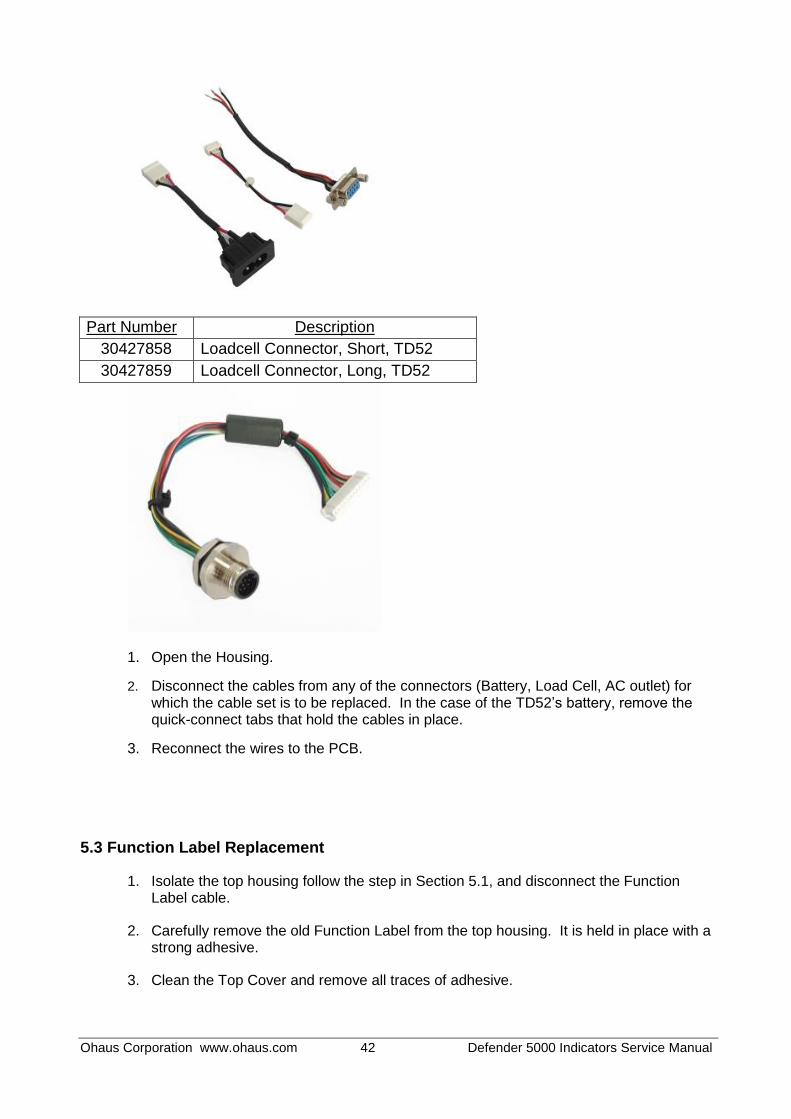
5.3 Cable Set Replacement
Cables set information:
Part Number Description
30427860 Internal Cable Kit, TD52
Ohaus Corporation www.ohaus.com 42 Defender 5000 Indicators Service Manual
Part Number Description
30427858 Loadcell Connector, Short, TD52
30427859 Loadcell Connector, Long, TD52
1. Open the Housing.
2. Disconnect the cables from any of the connectors (Battery, Load Cell, AC outlet) for which the cable set is to be replaced. In the case of the TD52’s battery, remove the quick-connect tabs that hold the cables in place.
3. Reconnect the wires to the PCB.
5.3 Function Label Replacement
1. Isolate the top housing follow the step in Section 5.1, and disconnect the Function Label cable.
2. Carefully remove the old Function Label from the top housing. It is held in place with a strong adhesive.
3. Clean the Top Cover and remove all traces of adhesive.
Ohaus Corporation www.ohaus.com 43 Defender 5000 Indicators Service Manual
4. Remove the protective backing from the back of the new Function Label. Carefully position it on the Top Housing, starting at the bottom of the cover. Use a rolling motion to smooth it into position.
5. Reconnect the Function Label cable and reserve step 1 to complete the indicator assembly.
6. Power on for the function test.
5.4 Transformer Replacement
1. Unplug the Indicator from the AC power source.
2. Separate the Top Housing and Bottom Housing follow the step in Section 5.1.
3. Remove the cable connector from the Transformer to the Main PCBA.
4. Remove the cable connector from the Transformer to the AC Inlet connector.
5. Remove the four screws that secure the Transformer to the bottom housing, and lift it off.
TD52P TD52XW
6. Position the replacement Transformer with the screw holes aligned.
7. Attach the two cables from the Main PCBA and AC Inlet.
WARNING: Electric Shock Hazard. Disconnect the Indicator from power before
servicing.
CAUSION: Observe precautions for handling electrostatic sensitive device.

Ohaus Corporation www.ohaus.com 44 Defender 5000 Indicators Service Manual
8. Secure the Transformer with four screws, and reserve step 2 for Housing assembly
9. Connect the Indicator to AC power and test it.
Note: Kindly take note of the cable routing from the Transformer within the bottom housing.

Ohaus Corporation www.ohaus.com 45 Defender 5000 Indicators Service Manual
APPENDIX A. CONFIGURING THE MAIN PCBA
Note: To perform the configuration, the RS232 option (PN: 30101019) needs to be installed on the
indicator. Once installed, connect the cable between indicator and computer.
Once a new Main PCBA is installed one will need to configure the new Main PCBA according to their
region.
1. Down load and install OHAUS Service and Repair Tools (Version 2.2.0.0 and later).
2. Open the software and select 'Repair Tool' and click 'Next'
3. Select 'TD52' under Product Selection and click 'Next'.
4. Select 'Replace Main PCB', click 'Next'
5. Set the same protocol setting between indicator and computer and click 'Next'.
6. Input the 'Serial Number' and 'Model Number' , Select the 'Shipping Country' from the location list and click 'Next'.
7. You will see the below window screen when the configuration is completed successfully.

Ohaus Corporation www.ohaus.com 46 Defender 5000 Indicators Service Manual
8. Turn OFF and ON the indicator and check if the configuration is correct.
9. If the process fail kindly check the below.
* The communication cable pin configuration.
* The Indicator Protocol setting.
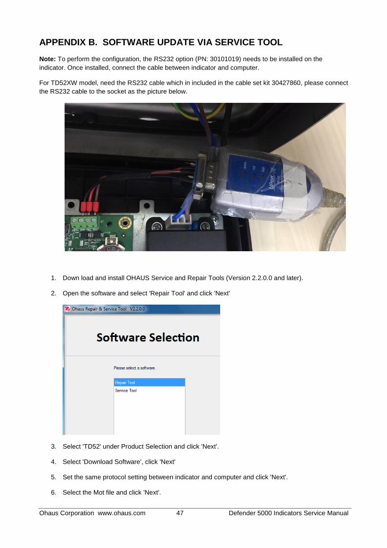
Ohaus Corporation www.ohaus.com 47 Defender 5000 Indicators Service Manual
APPENDIX B. SOFTWARE UPDATE VIA SERVICE TOOL
Note: To perform the configuration, the RS232 option (PN: 30101019) needs to be installed on the
indicator. Once installed, connect the cable between indicator and computer.
For TD52XW model, need the RS232 cable which in included in the cable set kit 30427860, please connect
the RS232 cable to the socket as the picture below.
1. Down load and install OHAUS Service and Repair Tools (Version 2.2.0.0 and later).
2. Open the software and select 'Repair Tool' and click 'Next'
3. Select 'TD52' under Product Selection and click 'Next'.
4. Select 'Download Software', click 'Next'
5. Set the same protocol setting between indicator and computer and click 'Next'.
6. Select the Mot file and click 'Next'.
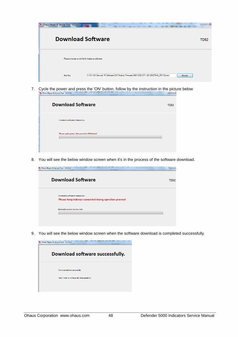
Ohaus Corporation www.ohaus.com 48 Defender 5000 Indicators Service Manual
7. Cycle the power and press the 'ON' button, follow by the instruction in the picture below
8. You will see the below window screen when it's in the process of the software download.
9. You will see the below window screen when the software download is completed successfully.

Ohaus Corporation www.ohaus.com 49 Defender 5000 Indicators Service Manual
APPENDIX C. SOFTWARE UPDATE VIA MICRO SD CARD
Note: Need prepare the Micro SD card for this process.
1, Create the new folder "D5000" under the root folder of the Micro SD, and "Update" under "D5000" 2, Copy the mot file in the folder "Update" with the name "30427649.mot"
3, Insert the Micro SD card into the SD card Slot (Make sure indicator is powered off for this step)
TD52P TD52XW 4, Power on and long press the button "User/Menu" entry to the Menu, Scroll to the Main Menu "Maintenance" as the picture below:
5, Scroll to the Sub Menu "Service Menu" and enter the Password 64852
6, Scroll to "Firmware Update", press the Softkey corresponding to the icon for the software upgrade

Ohaus Corporation www.ohaus.com 50 Defender 5000 Indicators Service Manual
7, The indicator will be switched off automatically, when it's done with the software upgrading 8, Switch on the indicator to check the software version, when program startup.

OHAUS Corporation
7 Campus Drive
Suite 310
Parsippany, NJ 07054 USA
Tel: +1 973 377 9000
Fax: +1 973 944 7177
With offices worldwide
www.ohaus.com
*30479277A*
P/N 30479277A © 2018 OHAUS Corporation, all rights reserved