deep dive into revit structure analytical tools - …lukewarmcoffee.com/revit/au - dive deep into...
TRANSCRIPT

[Type text] Deep Dive Into Revit® Structure Analytical Tools
1
Deep Dive Into Revit® Structure Analytical Tools Joseph Charpentier – Autodesk, Inc.
Code: SE210-1
Join the Revit Structure product manager for a detailed presentation of the analytical tools available within the software. You’ll see advanced techniques for structural analysis modeling. You will also learn more about RISA, ADAPT and ETABS software for structural analysis and design.
Key Topics: - Analytical versus physical models - Analytical/physical model consistency checks - Adjust/reset analytical model - Member support checks - Analytical functionalities in Revit Structure (auto-detect) - Boundary conditions - Link to 3rd party structural analysis and design software
Who Should Attend Structural engineers and designers who want to have an in depth understanding of Revit Structure analytical tools
About the Speaker:
Joe has been a Quality Assurance Analyst for Autodesk Revit Structure since 2005. Prior to that, he worked as a Structural Engineer for several small and mid-sized consulting firms in the northeast, working primarily on low-rise commercial, education, and residential projects. You can contact him at [email protected]

[Type text] Deep Dive Into Revit® Structure Analytical Tools
2

[Type text] Deep Dive Into Revit® Structure Analytical Tools
3
1. Physical versus analytical models
2. Analytical views and display options
3. Checking Member Supports
4. Checking Analytical / Physical Model Consistency
5. Adjusting analytical models
• Beams and braces
• Walls
• Columns
• Slabs
6. Adding Analytical model in Families
7. Boundary conditions
8. Defining Loads
9. Link to structural analysis software 1. Physical versus Analytical models
Key idea: - one physical model drives the modeling and documentation process - one analytical model drives the analysis process - analytical model can be adjusted for analysis purposes while the physical model stays accurate for
documentation

[Type text] Deep Dive Into Revit® Structure Analytical Tools
4
2. Analytical Views and Display options
Display options
Display options for analytical model are controlled by the visibility dialog box. Each object that can generate an analytical representation has a subcategory that can be customized
Colors are controlled from the Object Styles dialog box:
View templates
Analytical views are not created automatically. The default template provides an analytical view for the level 2 plan view and for a 3D view
In order to create a specific view to display the analytical model, you need to:
- duplicate an existing view (right click on the project browser)
- possibly rename the new view (right click on the project browser)
- select the command [View][Apply View Template]
- select “structural analytical normal” that will display analytical and physical model or “structural analytical stick” that will display the analytical model only
3. Checking Member Supports
This tool is used to detect missing supports in the model before the model is sent to analysis.
Warnings will help find unsupported elements and these elements are highlighted for visual reference.

[Type text] Deep Dive Into Revit® Structure Analytical Tools
5
Circular references
4. Checking Analytical / Physical Model Consistency
To find inconsistencies within the Analytical Model or between the Analytical and Physical Models
Checks can be "Automatic" or "On-Demand“

[Type text] Deep Dive Into Revit® Structure Analytical Tools
6
5. Adjusting analytical models
This tool is used based on engineering judgment to adjust the analytical model in order to generate an accurate structural analysis model. The short cut for [Tools][Adjust Analytical model] is AA.
The short cut for [Tools][Reset Analytical model] is RA. Beams and braces
Adjust location of analytical model horizontally
Case 1:: we want to the end point of analytical model of beam A and B to be located at the same point. Here we decide to move the end of beam A:
before after
- use short cut AA
- place the mouse on top of the end that you want to adjust and click it
- move the mouse to the end of the second member and select the tab key until you see a square at the end of beam B
- select it
Case 2:: we want the 2 beams to be connected for analysis
before after
- AA
- Select end of the beam on the left
- Select beam on the right and you get the analytical model extended:
The RA shortcut will reset the analytical model of the element you select.

[Type text] Deep Dive Into Revit® Structure Analytical Tools
7
Adjust analytical model vertically
For vertical adjustment, the same operation can be done in an elevation view or in a 3D view.
If it is desirable to project vertically the entire analytical model of the beam then you just need to change the analytical projection plane from the property dialog box of the beam:
Auto-detect
Instead of adjusting the analytical models manually, the analytical models of structural element have the ability to adjust their location to attached/adjacent element’s analytical projection planes.
In Structural Settings> Analytical Model Settings> Tolerances are the maximum distance an analytical model can adjust with respect to its default location:
Beams can also be automatically adjusted horizontally to walls and edges of slabs
Instead of manually changing the vertical projection to Level 2, the auto-detect feature will make the analytical vertical projection of beams (orange dots below) to coincide with the location of slabs.
“Auto-detect” - OFF
“Auto-detect” - ON

[Type text] Deep Dive Into Revit® Structure Analytical Tools
8
Release conditions
Release condition definitions are available for each beam in the property dialog box and are defined in local coordinate system of the element.
Walls
Adjust analytical model horizontally
Analytical models of walls can be projected to any reference plane.
Case:: remodeling of an historic building where walls are not straight
When we run the structural analysis, we want to model this situation as a straight wall.
In that case we create a reference plane (and name it) where we want to project the walls and we change the analytical projection plane of the wall from its property dialog box:
And we get:
[Type text] Deep Dive Into Revit® Structure Analytical Tools
9
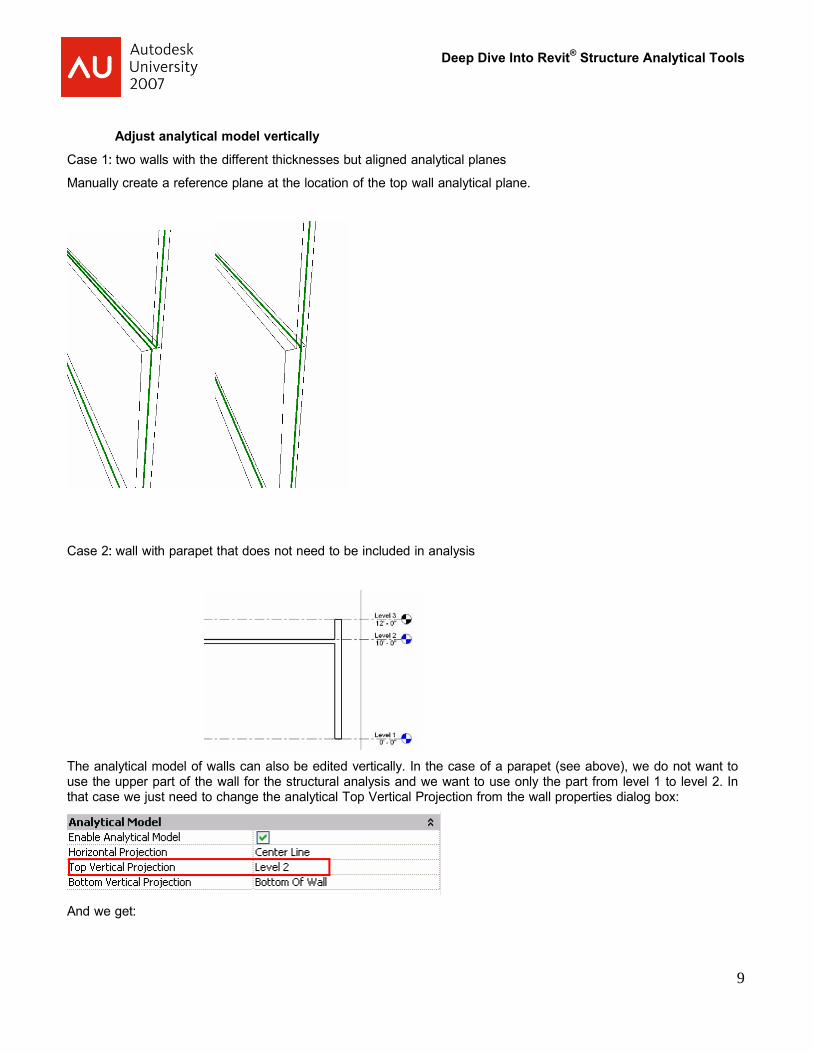
Adjust analytical model vertically Case 1:: two walls with the different thicknesses but aligned analytical planes
Manually create a reference plane at the location of the top wall analytical plane.
Case 2:: wall with parapet that does not need to be included in analysis
The analytical model of walls can also be edited vertically. In the case of a parapet (see above), we do not want to use the upper part of the wall for the structural analysis and we want to use only the part from level 1 to level 2. In that case we just need to change the analytical Top Vertical Projection from the wall properties dialog box:
And we get:

[Type text] Deep Dive Into Revit® Structure Analytical Tools
10
The same principle could be applied for the bottom of the wall
A slope reference plane could also be used.
Remove walls from analysis
In case we do not want a wall to be part of the analysis, you can uncheck its analytical property from the dialog box:
Reset analytical model
Using the RA command will reset the analytical model of the selected elements
Auto-detect
With manual adjustment of analytical model, extensive amount of work might be required when these situations occur multiple times in a project. It is sometimes not possible to assign a new reference plane on creation. To align walls, you need to create a named reference plane then assign each of the analytical projection planes to that reference plane. Changing the analytical plane of the walls may also require a manual change of the reference plane.
With auto-detect, these analytical adjustments are automated.
For elements of the same category (wall-to-wall, slab-to-slab, etc), auto-detect is based on the order of creation, with highest priority given to the element created first.
The exception to this rule is that if the analytical projection parameter has been changed from “auto-detect” for one of these elements, then that element will have the highest priority.

[Type text] Deep Dive Into Revit® Structure Analytical Tools
11
Wall 1 is the first created wall, followed by Wall 2, then by Wall 3, all of which are set to auto-detect.
If the horizontal projection of Wall 2 is changed to center line, then analytical projection of Wall 3 and Wall 1 will align to the centerline of Wall 2.
If the horizontal projection of Wall 2 is changed back to auto-detect, then horizontal projection of Wall 3 and Wall 1 will move back to the original state (centerline of Wall 1).
If more than one object’s analytical parameter has been changed, then priority is given to one of these elements based on element ID
Note: Analytical models for arc walls will not adjust.

[Type text] Deep Dive Into Revit® Structure Analytical Tools
12
“Auto-detect” - OFF “Auto-detect” - ON
Columns
Adjust location of analytical model horizontally
In this type of situation and in order to have a more accurate model, if the selected analysis software supports rigid links, then the links could be modeled between columns and beams. In order to do that, select the column and check its rigid link property:
And we get:
The analytical model of the exterior columns can be adjusted as well:
- select the column with one click
- drag the center blue dot from the column to the desired location

[Type text] Deep Dive Into Revit® Structure Analytical Tools
13
The adjust analytical tool is also available for columns
Adjust analytical model vertically
Top and bottom location of analytical model can be controlled via the column property dialog box, just like for the walls:

[Type text] Deep Dive Into Revit® Structure Analytical Tools
14
Auto-detect horizontal projection
Release conditions
Release condition definitions are available for each column in the property dialog box and are defined in local coordinate system of the element.
Slabs
The analytical model of slabs is handled differently than the other objects in the sense that the sketch of the slabs defines the analytical model and the physical is entered by offsetting the edges of the slab with the cantilever parameters (the dots represent the analytical model edge):
Adjust analytical model vertically
The analytical projection plane of the slab can be adjusted from the properties dialog box:

[Type text] Deep Dive Into Revit® Structure Analytical Tools
15
Auto-detect
If a slab edge created using non-linear sketch lines (arc, ellipse, spline) is set to auto-detect, and it falls within tolerance of a linear, the analytical line will become straight.
“Auto-detect” - OFF
“Auto-detect” - ON
Remove slab from analysis If the slab is not part of the analysis, you need to uncheck its analytical property from the dialog box:
The sketch will only define the physical model.
Best practices for analytical settings
Based on the analysis software capabilities that will be used:
- Decide to use auto detect features or manual ones
- Choose the planes where the analysis will be performed
o An existing level o An arbitrary plane: draw the plane in elevation view and give it a name

[Type text] Deep Dive Into Revit® Structure Analytical Tools
16
- Select all beams and assign the analytical projection plane
- Select all slabs and assign the analytical projection plane
- Select all walls and assign the top and bottom analytical projection plane
- Select all columns and assign the top and bottom analytical projection plane
- Adjust each plan to reflect local conditions
6. Adding Analytical model in Families
- From modeling Design tab, select [Create][Structural framing] member
- Select Solid Sweep:
- Sketch a path - Select a profile
- Select model line and analytical projection type:
- Draw the line that will represent the analytical model
7. Boundary Conditions Elements
These elements are to model how the structure is attached to its points of support.
Point Boundary
Only structural beam, column and brace ends are available for point restraint
Line Boundary
Line restraint is limited to the individual analytical lines for structural beams, walls, wall foundations, slabs and slabs

[Type text] Deep Dive Into Revit® Structure Analytical Tools
17
foundations.
Area Boundary
Area restraint applies to analytical face for structural slabs, walls and foundation slabs
8. Defining Loads
Point loads, line loads and area loads can be defined from one single command located in the modeling tab. The option bar proposes different shape of loads:
Line loads and area loads with host are generated by picking elements (hosts) and they are adjusted if the geometry of the host changes.

[Type text] Deep Dive Into Revit® Structure Analytical Tools
18
Load cases and Load combinations
Load cases and load combinations can be entered from the menu [Settings][Structural settings]
Load coordinate system
Loads are generated in user defined plane:
If “Orient to” property is set to “workplane” then Z will be normal to workplane.
If “Orient to” property is set to “project” then Z will be normal vertical in global coordinate system.
“Is reaction” parameter is a flag to filter the external loads created by a user and the internal loads (or reactions) created by 3rd party analysis software. Internal loads can be extracted by analysis software.
Note:
Loads can be tagged and scheduled.
Load Cases and Combinations can be transferred from one project to another one, using “Transfer project standards”
9. Round trip to analysis
Use Selection filter How to analyze structural elements:

[Type text] Deep Dive Into Revit® Structure Analytical Tools
Workflow between Revit Structure and 3rd party structural analysis software
19

[Type text] Deep Dive Into Revit® Structure Analytical Tools
The RISA-Revit Link Revit Structure users can now leverage the full power of Building Information Modeling by synchronizing their Revit Structure models with RISA-3D and RISAFloor. As an Autodesk Authorized Developer, RISA Technologies has created a full-fledged bi-directional exchange link with Revit Structure.
New models can be created in either Revit Structure or RISA software using the information available in the other program. All geometric and design information including materials, family instances, walls, slabs, openings, grid lines, boundary conditions, footings, loads and load combinations can be created / updated / deleted in either of the two programs using the information available in the other program.
The new exchange file method allows continuity of data flow throughout the exchange cycle. Users can add new elements and/or additional design to the RISA model and these changes will be retained in RISA while round-tripping.
The robust Excel based XML mapping file provides the capability to customize the processing of shapes, materials and load cases. A log file is created during every export / import operation giving a synopsis on the number of elements translated and errors/warnings encountered, if any.
20

[Type text] Deep Dive Into Revit® Structure Analytical Tools
21
Why Revit Structure and RISA? Imagine relocating a stairwell in an office building – re-framing, redesigning, updating drawings. In the past, a task like this would have taken hours. Likely you would re-frame plans and hand mark-ups to the draftsman. While new framing was making its way onto the plans, you’d manually update the analytical model, rerun the analysis/design, and then pour over the results. With a new design in hand, you’d tag new sizes on the updated plans, spending more time than you’d like cutting sections.
With Revit Structure, you’re already ahead of the curve. Every change – be it new framing, sizes, decks, notes – is automatically updated on all drawings in your set. Even sections! If only the same were true for your analysis software. With the latest versions of RISA programs and Revit Structure it is! Now you have the full power of RISA programs behind every step you make with Revit Structure.
Export the entire Revit Structure model, or just a selected subset, to either of the RISA programs. Perform static or dynamic analyses, moving load analyses, vibration loading, live load reduction, automatically generate seismic and wind forces, design elements using provisions from various countries and tie the results back to your Revit Structure model. See the results...on the drawings and in your project budget.
[Type text] Deep Dive Into Revit® Structure Analytical Tools
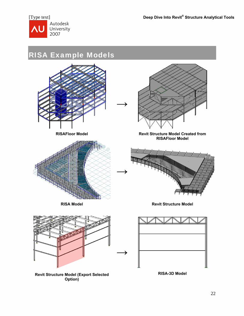
RISA Example Models
→
RISAFloor Model Revit Structure Model Created from RISAFloor Model
→
RISA Model
Revit Structure Model
Revit Structure Model (Export Selected
Option)
→
RISA-3D Model
22

[Type text] Deep Dive Into Revit® Structure Analytical Tools
RISA Data Exchange
Data Elements RISA-3D RISAFloor
Imports Exports Imports Exports Grid Lines
Floor/Level Information
Columns, Beams, and Braces
Cantilever Beams *
Physical / Multilevel Columns In-Place Families
Boundary Conditions
Footings
Structural Walls
Deck/Slab Definitions Deck/Slab Perimeter Deck/Slab Openings Materials
Load Cases
Load Combinations
Point Loads
Line Loads
Area Loads
Area Load Definitions * ‘Cantilever Moment’ flag is not preserved
23

[Type text] Deep Dive Into Revit® Structure Analytical Tools
RISA Mapping Files The link provides additional functionality for user-defined mapping of shape names, materials and RISAFloor Load Cases. This mapping is not mandatory for the functioning of the link, however its use is recommended to customize the import and export operations. The Excel based XML mapping file, “RISA_Revit_Mapping_File.xml” is copied during the RevitRISAComponent Installation.
Shape Mapping This spreadsheet consists of three columns: “RISA ShapeName”, “REVIT ShapeName” and “ShapeType”. By default it is filled with the mapping for all AISC Hot Rolled Shapes. A couple of examples have been appended at the end of the list for demonstration purposes. Any other shapes can be added at any time to this spreadsheet.
The link would first look for a mapping on this spreadsheet. If not found, it will try to process the shape using internal algorithms as mentioned below. If no processing is possible, then the shape name would be transferred ‘as is’ from one software to the other.
Material Mapping This spreadsheet consists of three columns: “RISA MaterialName”, “REVIT MaterialName” and “MaterialType”. By default it is filled with a logical mapping for all default materials and ‘WallType’ that exist in REVIT Structure. Any other mappings can be added at any time to this spreadsheet.
RISAFloor Load Case Mapping This spreadsheet consists of three columns: “RISA LoadCaseName”, “REVIT LoadCaseName” and “LoadCaseType”. By default it is filled with a logical mapping for all default Load Cases that exist in REVIT Structure. Any other mappings can be added at any time to this spreadsheet.
The reason why this mapping is essential for RISAFloor is that RISAFloor has specific load cases and user defined load cases cannot be added to the program. On the contrary, RISA-3D supports user defined Load Cases and hence, it does not require Load Case Mapping.
RISA-Revit Two Way Interaction A two file methodology has been implemented to preserve the elements that are added within RISA Software along with the elements being brought over from REVIT Structure. A base file, created by the RISA programs, would contain all the information about the structure, including new additions or modifications to properties made in the RISA software that are not directly possible in REVIT Structure. An exchange file, created by REVIT Structure, will contain all information that is being exported from REVIT Structure to RISA software. While updating data from RISA to REVIT Structure, the two file methodology helps in deleting elements in REVIT Structure that have been deleted in RISA.
The overall data has been primarily divided into two subsets:
1. Merge Subset: Refers to the data that is present in REVIT Structure and also in RISA Software. Common examples of this data are beams, columns, footings, materials etc. This data can be
24

[Type text] Deep Dive Into Revit® Structure Analytical Tools
25
added and modified in both REVIT Structure and RISA Software. The changes to this data can be made in either REVIT Structure or RISA Software.
2. Preserve Subset: Refers to the data that is present in the RISA Software only. Common examples of this data are design rules, hot rolled section sets, diaphragms, moving loads, etc.
Version Information Component Information
RevitRISAComponentVersion 6.0
Compatibility Information
Product Version REVIT Structure 2008 Service Pack 2
RISA–3D 7.0.2 or Higher RISA Floor 3.1.2 or Higher
Download Links
RevitRISAComponent www.risatech.com/partner/revit_structure.asp
REVIT Structure www.autodesk.com
RISA – 3D www.risatech.com/risa-3d.asp
RISAFloor www.risatech.com/risafloor.asp
Contact Information – RISA Technologies Foothill Ranch, CA Atlanta, GA
Amber Freund, P.E. Regional Engineer, Western USA
Mark Allphin, P.E. Regional Engineer, Eastern USA
949-951-5815 770-971-7405

[Type text] Deep Dive Into Revit® Structure Analytical Tools
26
Best practices for Slab Design Process using Revit Structure and ADAPT-Builder® The ADAPT-Builder suite of structural concrete design software offers a unique 3D model-based approach to slab system, mat foundation, beam, and beam frame designs. Using ADAPT-BIM technology, each structural component including reinforcement bars and post-tensioning tendons are modeled in their true 3D physical form, allowing you to manage and incorporate them in your design with ease. Structural Engineers using Revit Structure can take full advantage of ADAPT’s unique modeling capabilities by transferring all relevant model information from Revit Structure to ADAPT-Builder using a bi-directional integration link. ADAPT-Builder then transforms the physical model data into an accurate 3D FEM analysis model. Dynamic Rebar Design® capabilities give the designing engineer full control over the layout, rotation, specification, and placement of mild reinforcement using fully editable 3D rebar objects. When completed, all design changes and designated reinforcement can be transferred to the central Revit Structure for project coordination and creation of construction documents. This fully integrated concrete design process eliminates the need of redundant data entry, eliminates potential translation errors, saves time, and results in a BIM-based design model that is easy to maintain. ADAPT-Builder suite includes the following specialized software: ADAPT-Modeler, ADAPT-Floor Pro, ADAPT-MAT, and ADAPT-SOG. The following steps outline best practices for using Revit Structure and ADAPT-Builder.
1) Generate and Maintain Primary Project Model in Revit Structure a. Model all structural components in Revit using their true physical form. b. Maintain project-specific design criteria such as loading, load combinations and material properties
in your Revit Structure model. c. Remember to model structural components like columns one floor at a time – this will allow ADAPT
to extract the one floor system at a time with its associated supports below and above.
2) Export Model Data to ADAPT-Builder a. Using the bi-directional link provided by ADAPT, export all relevant project information to ADAPT-
Builder. b. Note that ADAPT does not require you to first define an analytical model. The transfer of model data
happens at the physical model level.
3) If Designing a Post-Tensioned Slab, Add Proposed Post-Tensioning to Model a. Apply desired post-tensioning to project model using fully editable 3D tendon models.
4) Carry out Detailed Slab and MAT Design Using ADAPT-Builder programs
a. ADAPT will automatically create a 3D FEM analytical model from the imported physical project model.
b. 3D FEM analysis results are interpreted and designed using ADAPT’s strip method function. c. For each design strip, the software checks the slab for code compliance and calculates required
reinforcement. d. The minimum required reinforcement is added to your slab or mat model as fully editable 3D rebar
objects.

[Type text] Deep Dive Into Revit® Structure Analytical Tools
27
5) Optimize Layout of Reinforcement in ADAPT-Builder
a. With the Dynamic Rebar Design feature, adjust the length, orientation, quantity, bar size, and spacing of reinforcement until you have your optimized rebar design.
b. This step is carried out completely in the ADAPT-Builder software by the design engineer and eliminates the need for multiple printouts and redlines that are passed back and forth to a drafting team.
6) Transfer Design Changes and Final Rebar Layout to Revit Structure
a. At the conclusion of your detailed slab or mat design in one of the ADAPT-Builder programs, transfer all of your design changes back to Revit Structure (e.g., change of column dimensions, addition of a beam, etc.).
b. Note that in many cases, the structural engineer is adding important design information to the ADAPT model such as loading, load cases, and load combinations. All of this information can be automatically transferred and updated in the central Revit Structure Model.
c. All reinforcement in ADAPT – base area reinforcement, individual bars, or distributed bars – can be transferred and added to the Revit Structure Model. Reinforcement bars transferred from ADAPT to Revit Structure are instances of area and path reinforcement families.
7) Produce Construction Documents using Revit Structure
a. Final construction documents including plan layouts and sections of your slabs and mats including the designed reinforcement are easily created and managed using Revit Structure.
8) Maintain Design Model in ADAPT
a. Because all design data in ADAPT-Builder programs is model based, all final design decisions, like the standardization of reinforcement bar sizes on a project, are stored in the data base and reusable in future design iterations.
9) Propagate Incremental Design Changes to RST
a. As project parameters change, incremental design changes made to the ADAPT or Revit Structure Model can be propagated back and forth between the two programs, ensuring complete compatibility between the main project model in Revit and design model in ADAPT.
In conclusion, ADAPT-Builder programs offer a high level of integration with Revit Structure that gives structural engineering firms using Revit Structure real productivity gains and improved design coordination. To find out more about how your firm can benefit from the ultimate concrete design process using Revit Structure and ADAPT software, please contact ADAPT at www.adaptsoft.com/revitstructure.