deceleration-based design auxiliary energy source for
TRANSCRIPT

Downloaded from engine.lib.uwaterloo.ca on 11 December 2021
Deceleration-based Design AuxiliaryEnergy Source for Electric VehicleApplications, version 2
Aree Wangsupphaphol, Nik Rumzi Nik Idris, Awang Jusoh,Nik Din MuhamadDate Submitted: 28 March 2015Date Published: 28 June 2015
Updated information and services can be found at:https://engine.lib.uwaterloo.ca/ojs-2.2/index.php/pptvt/article/view/693
These include:
Subject Classification Vehicular Technology
Keywords Energy management, Electric vehicles, Control design, DC-DC power converters, Supercapacitors, Batteries.;
Submitting Author'sComments
This paper is submitted to IEEE Transactions on VehicularTechnology.
Comments You can respond to this article at:https://engine.lib.uwaterloo.ca/ojs-2.2/index.php/pptvt/comment/add/693/0
Original Article https://engine.lib.uwaterloo.ca/ojs-2.2/index.php/pptvt/article/view/675
Copyright Copyright © Date Submitted: 28 March 2015 AreeWangsupphaphol et al. This is an open access articledistributed under the Creative Commons Attribution 2.5Canada License, which permits unrestricted use, distribution,and reproduction in any medium, provided the original work isproperly cited.

Deceleration-based Design Auxiliary Energy
Source for Electric Vehicle Applications
A. Wangsupphaphol, N. R. N. Idris, Senior Member, IEEE, A. Jusoh, and N. D. Muhamad
Abstract
This paper presents a new energy and power management control strategy for a battery hybrid
electric vehicle (BHEV) based on speed and acceleration. The purpose of control strategy is to
increase the ability of energy recapture during the vehicle deceleration and also to decrease the battery
voltage regulation and peak power. The proposed system includes the propulsion system; because of
supercapacitors (SCs) charging and discharging depend on the motoring or braking operations of the
vehicle. The control strategy uses cascade voltage and current control of SCs in order to control the
stored energy and power by tracking the vehicle speed and acceleration, taking the charging losses
into account. The electrical drive system is simplified by a mathematical model and the core features
of the control strategy have been presented. Numerical simulation demonstrates the effectiveness of
the proposed control strategy in term of battery peak power reduction, energy saving and battery
voltage regulation improvement compared to the ordinary battery electric vehicle (BEV). A small-
scale electromechanical experiment tests made on a 2 quadrant DC motor drive coupled with the
proposed system fully confirm the theoretical results.
Keywords
Electric vehicles, Control strategy, DC-DC power converters, Supercapacitors, Batteries.
I. INTRODUCTION
The rise of the specific power demand of the battery electric vehicle and the regenerative braking
energy capturing by the battery have drawn the interest of scientists on the problem involving the
reduction of peak power, voltage regulation and energy consumption. These problems concern
essentially to the battery power flow management. As known, the driving power consisting of the
tractive and dynamic power is represented by the set of mechanical equations. The maximum dynamic
power, which defines the maximum vehicle acceleration rate, requires a specific high battery current
that generates a significant decrease of voltage drop and increase of energy losses. In braking phase, on
the other hand, the battery can captures only a few amount of regenerative braking energy according to
Downloaded from engine.lib.uwaterloo.ca on 11 December 2021 Page 1 of 18

its specification. The remaining kinetic energy has to be dissipated by the mechanical braking system,
which generates heat and diffuses danger particles to the environment.
Currently, the hybrid energy source for electric vehicles proposed by many researchers mainly
focuses on implementing a single bidirectional dc-dc converter [1-6] or multiple converters [7-11]. A
single converter connecting to a single source, either main or auxiliary energy source, presents the bus
voltage varying while multiple converters implementation provide a constant bus voltage. The single
converter is workable because of the large input voltage acceptability of the traction inverter
technology nowadays that is able to accept from the maximum to the half of input voltage rated. On
the other hand, this condition reduces the inverter efficiency. The multiple converters implementation
fills the gap of this problem by maintaining the bus voltage where it relevance to the inverter
efficiency. However, it seems neutral because the increase weight and losses of the multiple
converters can be traded off with the lower weight and loss of using a single converter. Indeed, weight
increment significantly impacts to the vehicle dynamic in which it must be lowered as much as
possible; hence, a single converter can be a proper solution for electric vehicle applications.
Besides, some authors proposed new configurations of reducing a single converter rated either
battery or SCs [1], [4]. In [4], SCs have been shared by two parts and control only one of them. This
scheme produces SCs voltage twice the battery output voltage, and they absolutely require an
expensive and complex dynamic balancing circuitry. In [1], the battery is connected to a converter for
transferring energy to SCs. The battery can be directly connected to the traction inverter once SCs are
discharged lower than the minimum set point. This condition incurred the highest loss of inverter
because the inverter is feeding by the half of input voltage rating. From the application point of view,
both proposed technics have not provided the SCs size calculation and tested with a standard driving
cycle to observe their effectiveness. These can cause the inapplicable solution leading to the real-scale
applications. Though, the literature in [2], [3] evaluate the proposed SCs state of charge (SOC) control
techniques, load follower and neural networks, with a real car. The load follower control shows that it
consumes a slightly higher than neural network control because of the stored energy is discharged
inefficiently by the use of SOC looked-up table and the wide-band current limiter. However, the
implementation of neural networks control also requires precise knowledge, experience and high
processor performance. Thus, a proper method to design the SCs auxiliary energy source system for a
real-scale application is an uncomplicated procedure, and the system should be tested with a standard
driving cycle.
The main problem of the control strategy presented to date in the literatures is the proper real-time
estimation of the reference SCs current. An excessive set point means the fully discharge of SCs prior
the end of the acceleration period, with consequent of high battery voltage regulation and losses; a too
Downloaded from engine.lib.uwaterloo.ca on 11 December 2021 Page 2 of 18

low reference incurred a low utilization of SCs. To solve this problem, this paper proposes a new
control strategy for energy management of battery electric vehicle hybridized with SCs based on speed
and acceleration considering the SCs charging efficiency into account. The reference SCs voltage is
evaluated on the principle of an energy balancing between vehicle kinetic energy and SCs electrostatic
energy. The reference SCs current is obtained by the estimation of the reference vehicle speed and
acceleration. The effectiveness of the proposed control has been tested with the extra-urban driving
cycle (EUDC) in real-scale vehicle simulations and carried out on a small-scale experiment. Lastly,
this paper provides some considerations on the reduction of battery power, voltage regulation and
energy consumption.
II. SYSTEM CONFIGURATION
A. Battery Electric Vehicle
Battery electric vehicle is the vehicle powered by the battery main energy source. Nowadays, the
notable batteries using in the BEV are lithium based, sodium–nickel chloride, nickel- metal hydride
and lead-acid battery. In this study, lithium-ion battery is used and connected directly to the traction
inverter.
This paper refers to the city saloon vehicle, PROTON SAGA BEV, from PROTON Holding. The
vehicle is principally based on the internal combustion engine (ICE) vehicle chassis but changed the
energy source to be electric; the others components are the same as the ICE vehicle. The vehicle
characteristics are shown in the following table:
TABLE I
GENERAL CHARACTERISTICS OF PROTON SAGA BEV
𝑎/𝑑 [m/s2] 1.39/1.67 𝑀𝑉 [kg] 1000
𝐴𝑓 [m2] 2.098 𝑟𝑤ℎ [m] 0.26
𝐶𝑑 [-] 0.353 𝑣𝑉,𝑚𝑎𝑥 [m/s] 33.3
𝐺 [-] 1.429 𝜔𝑚,𝑚𝑎𝑥 [rps] 183.2
where 𝑎/d is the vehicle acceleration/deceleration rate, 𝐴𝑓 is the frontal vehicle area of vehicle, 𝐶𝑑 is
the aero dynamic drag coefficient, 𝐺 is the overall single gear ratio, 𝑀𝑉 is the vehicle mass, 𝑟𝑤ℎ is the
wheel diameter of vehicle, 𝑣𝑉,𝑚𝑎𝑥 is the vehicle maximum speed and 𝜔𝑚,𝑚𝑎𝑥 is the angular velocity of
motor. The propulsion system composes of a brushless DC motor 60 kW, connected to a three-phase
inverter. The battery is a bank of series connection of lithium-ion battery 32 cells, 7.5 V/cell, 42 A
Downloaded from engine.lib.uwaterloo.ca on 11 December 2021 Page 3 of 18
(standard charging, 1C) and 300 A (maximum current discharge). The bank provided 72 kW with the
equivalent internal resistance 52 mΩ.
B. Battery Hybrid Electric Vehicle
A hybrid power system is a combined two or more than two sources for a specific purpose. In
battery hybrid electric vehicle, the hybridization can be a combination of battery and others auxiliary
energy source (AES). Recent technology, flywheel (FW) and SCs are viable technologies to store the
dynamic power for using in acceleration and deceleration. However, FW, the energy storage
equipment by mechanical means, is under discussing on safety topics [12]; whereas, SCs have been
successfully accomplished by many hybrid electric vehicle application researches[4], [12-14] , so a
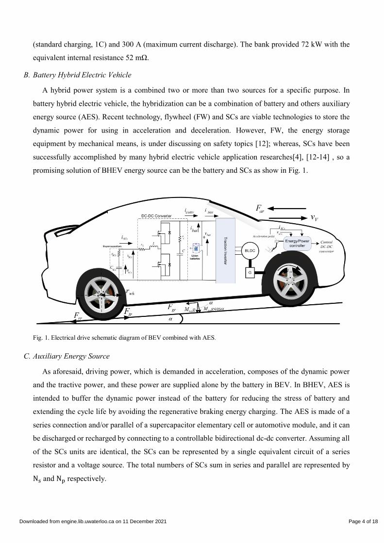
promising solution of BHEV energy source can be the battery and SCs as show in Fig. 1.
Fig. 1. Electrical drive schematic diagram of BEV combined with AES.
C. Auxiliary Energy Source
As aforesaid, driving power, which is demanded in acceleration, composes of the dynamic power
and the tractive power, and these power are supplied alone by the battery in BEV. In BHEV, AES is
intended to buffer the dynamic power instead of the battery for reducing the stress of battery and
extending the cycle life by avoiding the regenerative braking energy charging. The AES is made of a
series connection and/or parallel of a supercapacitor elementary cell or automotive module, and it can
be discharged or recharged by connecting to a controllable bidirectional dc-dc converter. Assuming all
of the SCs units are identical, the SCs can be represented by a single equivalent circuit of a series
resistor and a voltage source. The total numbers of SCs sum in series and parallel are represented by
Ns and Np respectively.
Downloaded from engine.lib.uwaterloo.ca on 11 December 2021 Page 4 of 18

In order to evaluate the capacity of SCs, the maximum vehicle kinetic energy referred to the energy
stored in the SCs but different by the involving losses. However, the capacity for supplying energy in
the acceleration is larger than that recovering energy in braking; therefore, the minimum capacity can
be obtained by referring to the regenerative braking energy. This consideration is not only reducing the
additional translating mass of the vehicle but also saving the cost. The SCs discharge boundary is
varied between the rated voltages to the half of the rated, which is recommended by the manufacturer
[15], so 75% of the energy stored is utilized. In acceleration, some of power from SCs is transferred to
the vehicle, and in deceleration it is recharged up to their initial SOC by the braking energy and
battery. For instance, SCs hold the maximum voltage when the vehicle stops; on the other hand, the
half of its rated voltage indicates the maximum speed of vehicle.
To calculate the actual energy available, the average efficiencies of the SCs 𝜂𝑆𝐶𝑠, converter
efficiency 𝜂𝑐𝑜𝑛𝑣, traction inverter efficiency 𝜂𝑖𝑛𝑣, brushless dc motor efficiency 𝜂𝐵𝐿𝐷𝐶, and
mechanical efficiency 𝜂𝑚𝑒𝑐ℎ are used as the system losses. Based on the efficiency specifications
provided by manufacturers, the SCs efficiency in high power pulsing is 𝜂𝑆𝐶𝑠 = 0.95, and the
efficiency of converter, traction inverter, motor and mechanic system are estimated as 𝜂𝑐𝑜𝑛𝑣 = 0.97,
𝜂𝑖𝑛𝑣 = 0.97, 𝜂𝐵𝐿𝐷𝐶 = 0.91 and 𝜂𝑚𝑒𝑐ℎ = 0.98 respectively. Therefore, the energy conservation
between the electrostatic energy stored in SCs and the maximum vehicle kinetic based on deceleration
can be evaluated as:
𝐶𝑆𝐶𝑠 [𝑉𝑆𝐶𝑠,𝑚𝑎𝑥2 − (
1
2𝑉𝑆𝐶𝑠,𝑚𝑎𝑥)
2] = 𝜂𝑡𝑜𝑡(𝑀𝑉 +𝑀𝑆𝐶𝑠)𝑣𝑉,𝑚𝑎𝑥
2 . (1)
where 𝐶𝑆𝐶𝑠 is the SCs capacitance, 𝑉𝑆𝐶𝑠,𝑚𝑎𝑥 is the maximum voltage of SCs, 𝑀𝑆𝐶𝑠 is the SCs mass,
𝜂𝑡𝑜𝑡 is the total efficiency (𝜂𝑆𝐶𝑠𝜂𝑐𝑜𝑛𝑣𝜂𝑖𝑛𝑣𝜂𝐵𝐿𝐷𝐶𝜂𝑚𝑒𝑐ℎ). In the preliminary calculation of SCs mass, the
weight can be set to be zero, but it will be updated and observed again in the final calculation.
Consequently, SCs capacitance can be derived by rewritten (1) as follows:
𝐶𝑆𝐶𝑠 = 𝜂𝑡𝑜𝑡(𝑀𝑉+𝑀𝑆𝐶𝑠)𝑣𝑉,𝑚𝑎𝑥
2
(3
4𝑉𝑆𝐶𝑠,𝑚𝑎𝑥2 )
. (2)
In particular, the bidirectional dc-dc converter manages between the power between SCs and
propulsion unit; it operates as a buck converter when charging SCs and a boost converter while
discharging. To design the converter, boost converter is considered due to it has more severities in
control design than the buck converter; after that, the buck converter is verified [11]. The maximum
voltage gain of boost converter is designated lower than 3, or it should has the duty ration in the
vicinity of 0.2-0.7, for the efficiency of boost converter is high [16]. In this case, the DC bus voltage is
260 V, so the SCs maximum voltage is selected at 200 V and is achieved by series connection of
Downloaded from engine.lib.uwaterloo.ca on 11 December 2021 Page 5 of 18

elementary cells or automotive modules. Therefore, the capacitance of a single cell is evaluated by the
following equation:
𝐶𝑆𝐶,𝑐𝑒𝑙𝑙 =𝐶𝑆𝐶𝑠∙𝑁𝑠
𝑁𝑝. (3)
where 𝐶𝑆𝐶,𝑐𝑒𝑙𝑙 is the capacitance of a supercapacitor, 𝑁𝑠 is the number of series connection and 𝑁𝑝 is
the number of parallel connection. 𝑁𝑠 can be obtained by dividing the maximum voltage of the SCs
bank by voltage rating of a single cell. 𝑁𝑝 is the prudential selection of an integer number to achieve
the available 𝐶𝑆𝐶,𝑐𝑒𝑙𝑙. After the 𝑉𝑆𝐶𝑠,𝑚𝑎𝑥 is chosen at 200 V, and the capacitance is obtained by 29.62
Farad, a bank of SCs can be achieved by a paralleling of series connection elementary cells, 1200
Farad, 2.7 V/cell, 74 units. The connection provides 32 Farad of capacitance with equivalent series
resistance 𝑟𝑆𝐶𝑠 = 21.5 mΩ and weight of 38.5 kg. After including the weight of the converter, the
additional weight is be estimated by 50 kg which is about 5% of the vehicle mass. The final calculation
is made and found that the rising capacitance and mass result a slightly increase of lower voltage
margin per designated, 100 V, while the vehicle dynamic is not effected.
The energetic sizing procedure achieved so far is based on the deceleration consideration.
Nonetheless, it is also compulsory to observe that if the deceleration power is acceptable for the SCs.
Thus, the recharge peak power to be recovered by the SCs is:
𝑃𝑆𝐶𝑠,𝑚𝑎𝑥 = 𝜂𝑚𝑒𝑐ℎ𝜂𝐵𝐿𝐷𝐶𝜂𝑖𝑛𝑣𝜂𝑐𝑜𝑛𝑣𝑀𝑡𝑜𝑡𝑣𝑉,𝑚𝑎𝑥𝑑 = 49 kW. (4)
where 𝑃𝑆𝐶𝑠,𝑚𝑎𝑥 is maximum peak power of SCs and 𝑀𝑡𝑜𝑡 = 𝑀𝑉 +𝑀𝑆𝐶𝑠 is total mass. Hence, the
maximum SCs current flowing in SCs is equal to:
𝐼𝑆𝐶𝑠,𝑚𝑎𝑥 =𝑃𝑆𝐶𝑠,𝑚𝑎𝑥
𝑉𝑆𝐶𝑠,𝑚𝑎𝑥/2 = 490 A. (5)
where ISCs,max is the rated current of SCs. Since the SCs are paralleled connection, the current of each
string is separated equally by 245 A, and this is validated by its specification, 1000 A.
III. MATHEMATICAL MODEL AND DESIGN OF THE PHYSICAL SYSTEM
A. Model of Vehicle
Basically, the vehicle dynamic load is modeled by the set of mechanical equations as follows:
Downloaded from engine.lib.uwaterloo.ca on 11 December 2021 Page 6 of 18

𝐹𝑡𝑟 = 𝐹𝑟𝑟 + 𝐹𝑎𝑟 + 𝐹𝑔𝑟 = 562.7 𝑁
𝐹𝑟𝑟 = 𝜇𝑟𝑟𝑀𝑡𝑜𝑡𝑔𝑐𝑜𝑠𝛼 = 49.4 𝑁
𝐹𝑎𝑟 = 0.5𝜌𝐴𝑓𝐶𝑑𝑣𝑉,𝑚𝑎𝑥2 = 513.3 𝑁
𝐹𝑔𝑟 = 𝑀𝑡𝑜𝑡𝑔𝑠𝑖𝑛𝛼
𝑇𝑤ℎ = 𝐹𝑡𝑟𝑟𝑤ℎ = 146.3 𝑁𝑚
𝑇𝑒𝑞 = 𝑇𝑤ℎ𝜂𝑚𝑒𝑐ℎ 𝐺⁄ = 100.3 𝑁𝑚
𝐺 = 𝜔𝑚,𝑚𝑎𝑥 𝜔𝑤ℎ,𝑚𝑎𝑥⁄ = 1.429.
(6)
where 𝐹𝑡𝑟 is the tractive resistance, 𝐹𝑟𝑟 is the rolling resistance generated between tires and road
surfaces, 𝐹𝑎𝑟 is the aerodynamic resistance , 𝐹𝑔𝑟 is the grading resistance that downgrades the force of
vehicle from going up, 𝑇𝑤ℎ is the load torque at wheel of the vehicle and 𝑇𝑒𝑞 is the equivalent load
torque transferred through the single gear ratio 𝐺. The coefficient values for calculation are as follow;
rolling resistance 𝜇𝑟𝑟 = 0.0048, Air density 𝜌 = 1.25 𝑘𝑔/𝑚3, aerodynamic drag 𝐶𝑑= 0.353, gravity
acceleration rate 𝑔 = 9.8 𝑚/𝑠2, and road grading angle α = 0 degree.
Based on the newton’s second law, the net force upon the object is the multiplication of the
acceleration and mass. Similarly, the net power in acceleration phase; that is, the multiplication of the
net force and velocity can be considered as the dynamic power. On the other hand, the power
counteracts to the tractive resistance in zero acceleration is the constant power namely tractive power.
These two powers are composed in driving power, which presents on the shaft of motor, and can be
defined by the following equation:
𝑃𝑑𝑟 = 𝑃𝑡𝑟 + 𝑃𝑑𝑦. (7)
where 𝑃𝑑𝑟 is driving power, 𝑃𝑑𝑦 is dynamic power, and 𝑃𝑡𝑟 is tractive power. To find the tractive
power, the equivalent torque and maximum angular velocity of the motor are used for calculation as is
given by the following relation:
𝑃𝑡𝑟 = 𝑇𝑒𝑞𝜔𝑚,𝑚𝑎𝑥 = 18.37 kW. (8)
In rotational motion, accelerating angular velocity and equivalent moment of inertia are used to
derive the torque; after that, the dynamic power can be defined. The dynamic power can be positive or
negative depends on the operating quadrant of the motor. In forward motoring, the dynamic power is
positive because of accelerating angular velocity is positive, and it is negative in forward braking. As
aforesaid, the dynamic power is rated to the braking energy; the decelerating angular velocity is used
to evaluate the SCs capacity as stated in the following equations:
𝑃𝑑𝑦 = 𝑇𝑑𝑙𝜔𝑚,𝑚𝑎𝑥 = 57.4 𝑘𝑊
𝑇𝑑𝑙 = 𝐽𝑒𝑞𝑑𝜔𝑚,𝑚𝑎𝑥
𝑑𝑡= 313.3 𝑁𝑚
𝐽𝑒𝑞 = 𝐽𝑚 + 𝜂𝑚𝑒𝑐ℎ𝑀𝑡𝑜𝑡(𝑟𝑤ℎ
𝐺)2 = 34.2 𝑘𝑔𝑚2.
(9)
Downloaded from engine.lib.uwaterloo.ca on 11 December 2021 Page 7 of 18
Where 𝐽𝑚 is the moment of inertia of the motor, 0.2 𝑘𝑔𝑚2, 𝐽𝑒𝑞 is the equivalent moment of inertia and
𝑇𝑑𝑙 is the dynamic load torque. The dynamic power is the power on the shaft of motor that used for
finding the power recharged to SCs considering the system losses.
𝑃𝑆𝐶𝑠,𝑚𝑎𝑥 = 𝑃𝑑𝑦𝜂𝑐𝑜𝑛𝑣𝜂𝑖𝑛𝑣𝜂𝐵𝐿𝐷𝐶 = 49.1 kW (10)
B. Model of SCs
A supercapacitor is a capacitor that has much larger capacitance than a conventional capacitor. The
SCs capacitance and the internal resistance are relatively slow changed over the time [17]. The
manufacturer models SCs as a transmission line in constant current discharge test for 20 seconds [18];
however, in pulsing charge and discharge, the conventional model, which is a series connection of a
resistor and a capacitor, is validated by some researchers [19-20]. In fact, the behavior of the SCs can
be described by the fundamental law of a capacitor; the instantaneous current is the function of the
instantaneous rate of the voltage change across the capacitor. Hence, the output voltage can be derived
by deducting voltage drop the internal resistance; 𝑟𝑆𝐶𝑠 = 𝑟𝑆𝐶,𝑐𝑒𝑙𝑙 × 𝑁𝑠 𝑁𝑝⁄ as represented by the
mathematic equations below:
𝑖𝑆𝐶𝑠(𝑡) = −𝐶𝑆𝐶𝑠𝑑𝑢𝑆𝐶𝑠
𝑑𝑡
𝑣𝑆𝐶𝑠(𝑡) = 𝑢𝑆𝐶𝑠 − 𝑟𝑆𝐶𝑠𝑖𝑆𝐶𝑠𝑢𝑆𝐶𝑠(0) = 𝑉𝑆𝐶𝑠,𝑚𝑎𝑥.
(10)
where 𝑢𝑆𝐶𝑠 is the internal voltage of SCs, 200 V, 𝑟𝑆𝐶𝑠 is the internal resistance of SCs, 21.5 mΩ,
𝑟𝑆𝐶,𝑐𝑒𝑙𝑙 is the internal resistance of a single cell of SCs, 0.58 mΩ, 𝑣𝑆𝐶𝑠 is the terminal voltage of SCs
and 𝑖𝑆𝐶𝑠 is the SCs current.
C. Model of battery
The model of lithium-ion battery main energy source is the used of the MATLAB/Simulink battery
block. It is made of a series connection of an internal resistance and a controlled voltage source
controlling by the continuous model. The energy availability, voltage and current of the battery are
defined as following; nominal voltage 240 V, rate capacity 81 Ah and initial SOC 95%. The battery
terminal voltage 𝑣𝑏𝑎𝑡 varies to its SOC and is deducted by the voltage across the internal resistance as
in the following equations:
𝑣𝑏𝑎𝑡 ∝ 𝑆𝑂𝐶
𝑣𝑏𝑢𝑠 = 𝑣𝑏𝑎𝑡 − 𝑟𝑏𝑎𝑡𝑖𝑏𝑎𝑡 (ss)
D. Model of Converter
Since the current of bidirectional converter in this study is continuous, the more severe controller,
the boost converter, is designed. To design the controller by using model based control, transfer
Downloaded from engine.lib.uwaterloo.ca on 11 December 2021 Page 8 of 18

function has to be derived. The transfer function of cascade control is considered, for the control
scheme is good at disturbance rejection and stability [21]. To find the transfer function at the quiescent
operating point, state space averaging technique is implemented for finding the duty ratio to current
and the current to voltage of SCs. Consequently, system matrices derived by using KVL during on and
off state 𝐴1,2, 𝐵1,2 and 𝐶1,2, are shown in the following equations:
𝐴1 = [
−(𝑟𝐿+𝑟𝑆𝐶𝑠)
𝐿0
0 −1
𝐶(𝑅+𝑟𝐶)
] , 𝐵1 = [1
𝐿
0] , 𝐶1 = [1 0]
; system matrices during on stage
𝐴2 = [
−(𝑅𝑟𝐶+𝑅(𝑟𝐿+𝑟𝑆𝐶𝑠))
𝐿(𝑅+𝑟𝐶)
−R
𝐿(𝑅+𝑟𝐶)
R
𝐶(𝑅+𝑟𝐶)
−1
𝐶(𝑅+𝑟𝐶)
] , 𝐵2 = [1
𝐿
0] , 𝐶2 = [1 0]
; system matrices during off stage
(16)
where 𝑅 is the equivalent resistance of maximum power, 1.38 Ω, 𝐿 is the converter inductance, 0.1
mH, 𝑟𝐿 is the equivalent inductive resistance, 0.02 Ω, 𝐶 is the converter output capacitance, 10 mF,
and 𝑟𝐶 is the internal resistance of output capacitor, 0.025Ω. To obtain the transfer function of duty
ratio to SCs current, the state equation is derived by the following equation:
𝐼𝑆𝐶𝑠(𝑠)
𝐷(𝑠)= 𝐶𝑠(𝑠𝐼 − 𝐴𝑠)
−1[(𝐴1 − 𝐴2)𝑋 + (𝐵1 − 𝐵2) 𝑈] + (𝐶1 − 𝐶2)𝑋 (17)
where 𝐷 is the duty ratio, 𝑋 is the equilibrium state vector and 𝑈 is the equilibrium input vector.
Equation (17) can be transformed to the standard equation of MATLAB transient response analysis
[22] as shown in the equations below:
𝐼𝑆𝐶𝑠(𝑠)
𝐷(𝑠)= 𝐶𝑠(𝑠𝐼 − 𝐴𝑠)
−1𝐵𝑠 + 𝐸𝑠 (18)
where 𝐴𝑠, 𝐵𝑠, 𝐶𝑠 and 𝐸𝑠 are the group of matrices as shown in the following equations:
𝐴𝑠 = 𝐴1𝐷 + 𝐴2(1 − 𝐷)
𝐵𝑠 = (𝐴1 − 𝐴2)𝑋 + (𝐵1 − 𝐵2)𝑈𝐶𝑠 = 𝐶1𝐷 + 𝐶2(1 − 𝐷)
𝐸𝑠 = (𝐶1 − 𝐶2)𝑋
(19)
Thereby, the duty ratio to inductor current can be derived. Then, the outer loop, SCs current to SCs
voltage transfer function can be recognized by the pure integrator of inverse capacitance. Subsequently,
the PI controller blocks available in MATLAB/Simulink are used for the controlling purpose. Figure 2
illustrates the transfer functions and their controllers:
Downloaded from engine.lib.uwaterloo.ca on 11 December 2021 Page 9 of 18

Fig. 2. Cascade control for the SCs
IV. CONTROL STRATEGY
The major purpose of the control strategy is to save the regenerative braking energy for supplying
in the next acceleration; this reduces the energy consumption. Besides, the strategy has to be able to
improve voltage regulation by reducing peak power of the battery. As regarded in section I, the
electrostatic energy stored in SCs can be referred to the vehicle kinetic energy on the basis of reference
value of the vehicle speed. By neglecting the small voltage drop on the internal resistance, the
reference internal voltage of SCs can be approximately used for tracking the vehicle speed as follows:
𝐶𝑆𝐶𝑠(𝑉𝑆𝐶𝑠,𝑚𝑎𝑥2 − 𝑢𝑆𝐶𝑠,𝑟𝑒𝑓
2) ≅ 𝜂𝑡𝑜𝑡𝑀𝑡𝑜𝑡𝑣𝑉,𝑟𝑒𝑓2
𝑢𝑆𝐶𝑠,𝑟𝑒𝑓 ≅ √𝑉𝑆𝐶𝑠,𝑚𝑎𝑥2 −
𝜂𝑡𝑜𝑡𝑀𝑡𝑜𝑡𝑣𝑉,𝑟𝑒𝑓2
𝐶𝑆𝐶𝑠.
(11)
where 𝑢𝑆𝐶𝑠,𝑟𝑒𝑓 is the reference SCs internal voltage and 𝑣𝑉,𝑟𝑒𝑓 is the reference vehicle speed. Equation
(11) shows the inverse relation between the reference SCs internal voltage and the reference vehicle
speed; the higher of reference vehicle speed, the lower of reference SCs internal voltage. Because of
the power is the multiplication between current and voltage, the dynamic power can be controlled by
using the cascade control of SCs voltage and current simultaneously. The current control achieves by
substituting the internal voltage of the capacitor fundamental equation in (10) with the approximate
reference SCs internal voltage in equation (11); the reference SCs current 𝑖𝑆𝐶𝑠,𝑟𝑒𝑓 is equal to:
𝑖𝑆𝐶𝑠,𝑟𝑒𝑓 = −𝐶𝑆𝐶𝑠𝑑𝑢𝑆𝐶𝑠,𝑟𝑒𝑓
𝑑𝑡≅
𝑀𝑡𝑜𝑡𝜂𝑡𝑜𝑡𝑣𝑉,𝑟𝑒𝑓
𝑉𝑆𝐶𝑠,𝑚𝑎𝑥
√1−(𝑀𝑡𝑜𝑡𝜂𝑡𝑜𝑡𝑣𝑉,𝑟𝑒𝑓
2
𝐶𝑆𝐶𝑠𝑉𝑆𝐶𝑠,𝑚𝑎𝑥2 )
𝑑𝑣𝑉,𝑟𝑒𝑓
𝑑𝑡. (12)
The above equation describes that the reference SCs current is the function of the vehicle speed and
acceleration or deceleration depending on the quadrant of motor operation. The SCs current direction
presents the behaviors of the power flow forth and back accordingly.
V. SIMULATION RESULTS
The behavior of the PROTON SAGA BEV, hybridized with the SCs, has been simulated by means
of the numerical simulation to verify the effectiveness of the proposed control strategy. Large signal
Downloaded from engine.lib.uwaterloo.ca on 11 December 2021 Page 10 of 18

simulation based on the real-scale vehicle parameters is executed. The block diagram of the simulation
composes of a bidirectional dc-dc converter, propulsion system, lithium-ion battery, SCs, PI
controllers and the proposed control algorithm as shown in Fig. 3.
Fig. 3. MATLAB/Simulink block diagram for the BHEV power train system.
In Fig. 3, input of the algorithm is the driving cycle speed for generating the reference voltage and
current comparing to the voltage and current feedback. Subsequently, the cascade control generates the
duty ratio supplying to the switches to control SCs current and voltage according to the speed
reference as described in the previous sections. The main parameters of the vehicle, converter and
energy sources reported in previous sections are implemented in the simulation. To compare the
performance of BHEV with BEV, the energy sources of both vehicles are set the same, for the BEV
battery mass is traded off with the BHEV energy sources as aforesaid.
In [23], the simulation of maximum acceleration has been preceded and compared the energy
consumption between BHEV and BEV. Whereas, the BEV is allowed to capture braking energy by 2
times of standard charging current; the BHEV is capable to save the cycle energy up to 6%. In fact,
recharging the battery by variant braking power can reduce the battery cycle life; therefore, the BEV
battery in this study is set unacceptable the braking energy.
In this work, the EUDC which composes of the varieties of speed and acceleration within 400 s is
used in order to validate the behavior of the real-scale simulation of BHEV. It is a standard driving
cycle providing the maximum speed of 120 km/h for testing the vehicle in manufacturing. The
highlighted significant are shown in Fig. 4(a)-(f). Fig. 4(a) shows the advantage of SCs hybridization
that provide the capability of assisting main source; the vehicle actual speed is followed to the
reference without using the mechanical brake in deceleration phase. The speed profile and SCs
voltage has inverse direction according to the reference SCs voltage created by (12). In Fig. 4(b),
reference and actual of SCs voltage are almost superimposed. The highlight is at t ≈ 330 s, the
maximum speed of vehicle reflects the minimum voltage of SCs according to the design principle of
the capacitance and voltage control. The presence of actual current along the driving cycle that agrees
Downloaded from engine.lib.uwaterloo.ca on 11 December 2021 Page 11 of 18
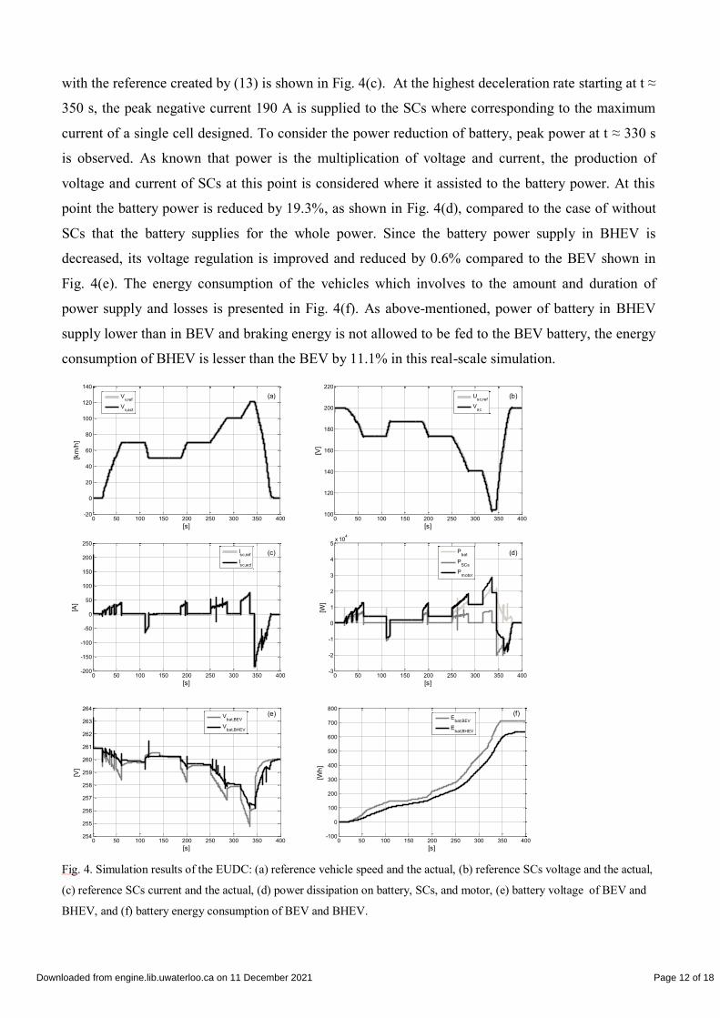
with the reference created by (13) is shown in Fig. 4(c). At the highest deceleration rate starting at t ≈
350 s, the peak negative current 190 A is supplied to the SCs where corresponding to the maximum
current of a single cell designed. To consider the power reduction of battery, peak power at t ≈ 330 s
is observed. As known that power is the multiplication of voltage and current, the production of
voltage and current of SCs at this point is considered where it assisted to the battery power. At this
point the battery power is reduced by 19.3%, as shown in Fig. 4(d), compared to the case of without
SCs that the battery supplies for the whole power. Since the battery power supply in BHEV is
decreased, its voltage regulation is improved and reduced by 0.6% compared to the BEV shown in
Fig. 4(e). The energy consumption of the vehicles which involves to the amount and duration of
power supply and losses is presented in Fig. 4(f). As above-mentioned, power of battery in BHEV
supply lower than in BEV and braking energy is not allowed to be fed to the BEV battery, the energy
consumption of BHEV is lesser than the BEV by 11.1% in this real-scale simulation.
Fig. 4. Simulation results of the EUDC: (a) reference vehicle speed and the actual, (b) reference SCs voltage and the actual,
(c) reference SCs current and the actual, (d) power dissipation on battery, SCs, and motor, (e) battery voltage of BEV and
BHEV, and (f) battery energy consumption of BEV and BHEV.
0 50 100 150 200 250 300 350 400-20
0
20
40
60
80
100
120
140
[s]
[km
/h]
Vv,ref
Vv,act
(a)
0 50 100 150 200 250 300 350 400100
120
140
160
180
200
220
[s]
[V]
Usc,ref
Vsc
(b)
0 50 100 150 200 250 300 350 400-200
-150
-100
-50
0
50
100
150
200
250
[s]
[A]
Isc,ref
Isc,act
(c)
0 50 100 150 200 250 300 350 400-3
-2
-1
0
1
2
3
4
5x 10
4
[s]
[W]
Pbat
PSCs
Pmotor
(d)
0 50 100 150 200 250 300 350 400254
255
256
257
258
259
260
261
262
263
264
[s]
[V]
Vbat,BEV
Vbat,BHEV
(e)
0 50 100 150 200 250 300 350 400-100
0
100
200
300
400
500
600
700
800
[s]
[Wh
]
Ebat,BEV
Ebat,BHEV
(f)
Downloaded from engine.lib.uwaterloo.ca on 11 December 2021 Page 12 of 18

VI. SMALL-SCALE ELECTROMECHANICAL EXPERIMENT RESULTS
Since the unavailability to establish into a laboratory the translational motion experiment and the
real power system of a vehicle, a small-scale electromechanical experiment has been set up
opportunely to verify the effectiveness of the proposed system as shown in Fig. 5. The experiment
composed of lead-acid batteries simulating the lithium-on batteries, SCs with a bidirectional dc-dc
converter and 2-quadrant DC motor drive system connecting with flywheels pretending the AC motor
drive system with high inertia load. The control part makes use of dSPACE DS1104 controller card
installed on a desktop computer.
Fig. 5. Front view of the small-scale electromechanical experiment.
A. The Experimental Set Up
The schematic diagram of the experiment is shown in Fig. 6 where current and voltage transducers
of battery, SCs, DC bus and DC motor are fed to the ADC ports for controlling and monitoring SCs
and DC motor. Also, the speed encoder signal, resolution of 200 pulse/revolution, is sent to the
incremental encoder interface connector of dSPACE to control the motor speed. After the feedback
data is sent to the controller, it will be executed correspondingly the control algorithm to generate the
duty ratio and sent to the 3 phase PWM signal generator whose produce the duty cycle supplied to the
switches of bidirectional dc-dc converters. For safety and star up the experiment, DC current limiting
fuses and switches are installed at the sources and motor.
Fig. 6. Schematic diagram of the small-scale electromechanical experiment.
Converters/switches
DS1104 Batteries
SCs
DC
motor
Downloaded from engine.lib.uwaterloo.ca on 11 December 2021 Page 13 of 18

The energy sources, converters and the DC motor drive system parameters are reported in Table II
where the batteries are series connected for 7 units to achieve the nominal voltage 84 V, and the SCs
are connected in series 30 cells to provide 80 V but limited using at 60 V.
TABLE II
EXPERIMENTAL PARAMETERS
Lead-acid battery
Rated/Floating voltage [V] 12/13.5
Maximum discharge/charge [A] 105/2.1
Capacity [Ah] 7
Internal resistance [mΩ] 23
Supercapacitor
Rated voltage [V] 2.7
Capacitance [F] 25
ESR [mΩ] 25
Bidirectional dc-dc converter
Inductor/ESR [mH/mΩ] 5/500
Output capacitor/ESR [mF/mΩ] 10/25
IGBT modules Fuji 2MBI100TA-060
DC motor and load
Rate voltage/current [V/A] 120/3.3
Rated power [W] 250
Rated speed [rpm] 3000
Weight/inertial (with flywheel) [𝑘𝑔/𝑘𝑔𝑚2] 14/0.03
B. Experimental Results
The EUDC test validates the contribution of SCs during acceleration and the capture ability of the
regenerative braking energy. Since the maximum voltage of battery supply to the motor is limited
using at 90 V; the maximum speed is 1750 rpm. This has been adapted to the EUDC to make the
reference angular velocity for the test. The behavior of the proposed drive system is obviously shown
in Fig. 7(a)-(f). Before starting the experiment, SCs is pre-charged to 60 V alike in the real vehicle
applications. Fig. 7(a) shows the reference and actual angular velocity completely superimposed. This
because of the assisting power supplied and captured by SCs. Fig. 7(b) shows the tracking capability
of SCs voltage according to the reference voltage profile. In promise with the proposed control
algorithm, SCs voltage reaches the minimum at 50 V when the motor runs at the maximum speed.
The minimum voltage is higher than its half rated (30 V) as intended due to the used of non-
Downloaded from engine.lib.uwaterloo.ca on 11 December 2021 Page 14 of 18

optimized SCs size which effects to the power pattern and energy scheme. Fig. 7(c) shows the actual
and reference SCs current that changes in sign following to the acceleration of driving cycle. The
current drops to zero at the end of acceleration and reaches the maximum negative current at the
highest deceleration t ≈ 330 s according to the simulation result. The presences of power flow is
shown in Fig. 7(d) where the highest peak power reduction at the last acceleration t ≈ 320 s is by 1 %.
This due to the oversize available SCs causes the low utilization of store energy and power. Thus,
SCs power, which is the production of voltage and current, supplied in acceleration phase is low and
result of low battery power reduction compared to the real-scale simulation result where the SCs
utilization is higher. Consequently, voltage regulation has the inverse result of the BHEV that higher
than BEV by 3.5% as shown in Fig. 7(e). Finally, the energy consumption has the same direction as
previous results that the BHEV consumes more energy than the BEV by 56.3% as shown in Fig. 7(f).
The extremely consumption of BHEV in the experiment is not only because of the low SCs energy
utilization but also the internal resistance of the battery, SCs and converter that have the value
incredibly higher than the real-scale simulation parameters by 3.1, 35 and 25 times respectively.
However, the energy consumption in the electromechanical experiment can be further developed
when a system design is optimized, based on the specific application, for a real system.
Downloaded from engine.lib.uwaterloo.ca on 11 December 2021 Page 15 of 18

Fig. 7. Experimental results of the adapted EUDC: (a) reference vehicle speed and the actual, (b) reference SCs voltage and
the actual, (c) reference SCs current and the actual, (d) power dissipation on battery, SCs, and motor, (e) battery voltage
of BEV and BHEV, and (f) battery energy consumption of BEV and BHEV.
VII. CONCLUSION
This paper presents a new control strategy and system configuration for a BHEV in order to reduce
battery peak power, improve the battery voltage regulation and saving energy. The proposed strategy
is by using cascade voltage and current control of SCs, for tracking the energy and power between
SCs and vehicle. The maximum power of SCs in application can be estimated by the maximum
vehicle deceleration rate to capture the whole regenerative braking energy. This paper also presents
the significant highlights of real-scale simulation and electromechanical experiment testing with the
EUDC diagram. The simulation results show that the reduction of peak power, voltage regulation and
energy consumption can be received up to 19.3%, 0.6% and 11.1% respectively. Similar to the
simulation, the experimental results exhibit the same trend as shown in speed, voltage, current and
power flow control. Nevertheless, the low utilization of SCs store energy and the highly internal
0 50 100 150 200 250 300 350 400-50
0
50
100
150
200
[s]
[rp
s]
Wref
Wact
(a)
0 50 100 150 200 250 300 350 40048
50
52
54
56
58
60
62
[s]
[V]
USCs,ref
VSCs
(b)
0 50 100 150 200 250 300 350 400-0.4
-0.3
-0.2
-0.1
0
0.1
0.2
0.3
[s]
[A]
ISCs,ref
ISCs,act
(c)
0 50 100 150 200 250 300 350 400-20
-10
0
10
20
30
40
50
60
70
[s]
[W]
Pmotor
PSCs
Pbat
(d)
0 50 100 150 200 250 300 350 40076
78
80
82
84
86
88
[s]
[V]
Vbat,BEV
Vbat,BHEV
(e)
0 50 100 150 200 250 300 350 4000
0.5
1
1.5
2
2.5
3
3.5
4
4.5
[s]
[W]
Ebat,BEV
Ebat,BHEV
(f)
Downloaded from engine.lib.uwaterloo.ca on 11 December 2021 Page 16 of 18

resistances of the lead-acid battery, SCs and the converter in the experiment cause of the
contradictory results of voltage regulation and energy consumption. The study gives the comment on
an optimization system design for a specific application in order to receive superior experimental
results.
ACKNOWLEDGEMENT
The Author would like to thank for finance supported by the Ph.D. Merit Scholarship of Islamic
Development Bank (IDB) for conducting the research at UTM-Proton future drive.
REFERENCES
[1] J. Cao and A. Emadi, “A new battery/ultracapacitor hybrid energy storage system for electric, hybrid, and plug-in hybrid electric vehicles,” Power
Electronics, IEEE Transactions on, vol. 27, no. 1, pp. 122–132, 2012.
[2] J. Moreno, M. E. Ortúzar, and J. W. Dixon, “Energy-management system for a hybrid electric vehicle, using ultracapacitors and neural networks,”
Industrial Electronics, IEEE Transactions on, vol. 53, no. 2, pp. 614–623, 2006.
[3] B. Arnet and L. Haines, “High power DC-to-DC converter for supercapacitors,” in Electric Machines and Drives Conference, 2001. IEMDC 2001. IEEE
International, 2001, pp. 985–990.
[4] G. Guidi, T. M. Undeland, and Y. Hon, “An interface converter with reduced VA ratings for battery-supercapacitor mixed systems,” in Power
Conversion Conference-Nagoya, 2007. PCC’07, 2007, pp. 936–941.
[5] S. Pay and Y. Baghzouz, “Effectiveness of battery-supercapacitor combination in electric vehicles,” in Power Tech Conference Proceedings, 2003 IEEE
Bologna, vol. 3, 2003, p. 6–pp.
[6] A. Wangsupphaphol, N. Idris, A. Jusoh, N. Muhamad, and L. W. Yao, “The energy management control strategy for electric vehicle applications,” in
Green Energy for Sustainable Development (ICUE), 2014 International Conference and Utility Exhibition on, 2014, pp. 1–5.
[7] L. Solero, A. Lidozzi, and J. A. Pomilio, “Design of multiple-input power converter for hybrid vehicles,” Power Electronics, IEEE Transactions on, vol.
20, no. 5, pp. 1007–1016, 2005.
[8] P. Thounthong, S. Raël, and B. Davat, “Energy management of fuel cell/battery/supercapacitor hybrid power source for vehicle applications,” Journal of
Power Sources, vol. 193, no. 1, pp. 376–385, 2009.
[9] O. Laldin, M. Moshirvaziri, and O. Trescases, “Predictive Algorithm for Optimizing Power Flow in Hybrid Ultracapacitor/Battery Storage Systems for
Light Electric Vehicles,” 2013.
[10] C. Romaus, J. Bocker, K. Witting, A. Seifried, and O. Znamenshchykov, “Optimal energy management for a hybrid energy storage system combining
batteries and double layer capacitors,” in Energy Conversion Congress and Exposition, 2009. ECCE 2009. IEEE, 2009, pp. 1640–1647.
[11] A. Florescu, H. Turker, S. Bacha, and E. Vinot, “Energy management system for hybrid electric vehicle: Real-time validation of the VEHLIB dedicated
library,” in Vehicle Power and Propulsion Conference (VPPC), 2011 IEEE, 2011, pp. 1–6.
[12] M. Steiner, M. Klohr, and S. Pagiela, “Energy storage system with ultracaps on board of railway vehicles,” in Power Electronics and Applications, 2007
European Conference on, 2007, pp. 1–10.
[13] H. Xiaoliang, J. M. A. Curti, and H. Yoichi, “Energy management strategy with optimized power interface for the battery supercapacitor hybrid system
of Electric Vehicles,” in Industrial Electronics Society, IECON 2013-39th Annual Conference of the IEEE, 2013, pp. 4635–4640.
[14] M. Ortúzar, J. Moreno, and J. Dixon, “Ultracapacitor-based auxiliary energy system for an electric vehicle: Implementation and evaluation,” Industrial
Electronics, IEEE Transactions on, vol. 54, no. 4, pp. 2147–2156, 2007.
[15] “WHITE PAPER DESIGN CONSIDERATIONS FOR ULTRACAPACITORS.” [Online]. Available:
http://www.maxwell.com/images/documents/technote_designinguide.pdf.
[16] R. W. Erickson and D. Maksimovic, Fundamentals of power electronics. Springer, 2001.
[17] “Top 10 Reasons for using Ultracapacitors in your system designs.” [Online]. Available:
http://www.maxwell.com/images/documents/whitepaper_top_10_reasons_for_ultracaps.pdf.
[18] bguillous, “Microsoft PowerPoint - IQPC Wiesbaden2010_MaxwellTechnologies_BSG2.ppt,” 2010.
[19] J. Wong, N. Idris, M. Anwari, and T. Taufik, “A parallel energy-sharing control for fuel cell-battery-ultracapacitor hybrid vehicle,” in Energy
Conversion Congress and Exposition (ECCE), 2011 IEEE, 2011, pp. 2923–2929.
[20] D. Iannuzzi and P. Tricoli, “Speed-based state-of-charge tracking control for metro trains with onboard supercapacitors,” Power Electronics, IEEE
Transactions on, vol. 27, no. 4, pp. 2129–2140, 2012.
Downloaded from engine.lib.uwaterloo.ca on 11 December 2021 Page 17 of 18

[21] K. Tsang and W. Chan, “Cascade controller for DC/DC buck convertor,” in Electric Power Applications, IEE Proceedings-, 2005, vol. 152, no. 4, pp.
827–831.
[22] K. Ogata, Matlab for control engineers. Pearson/Prentice Hall, 2008
[23] A. Wangsupphaphol, N. Idris, A. Jusoh, N. Muhamad, and L. W. Yao, “The energy management control strategy for electric vehicle applications,” in
Green Energy for Sustainable Development (ICUE), 2014 International Conference and Utility Exhibition on, 2014, pp. 1–5.
Downloaded from engine.lib.uwaterloo.ca on 11 December 2021 Page 18 of 18