ddam analysis - fetraining
TRANSCRIPT

1
DYNAMIC DESIGN AND ANALYSIS METHODDDAM AND MODAL EFFECTIVE MASS
TONY ABBEY
FETraining.com
www.fetraining.com
WWW.FETRAINING.COM

2
MODAL EFFECTIVE MASS THEORY
DDAM BACKGROUND.
SIMPLE DDAM ANALYSIS
MODAL DATABASE USAGE
BRACKET DDAM ANALYSIS – CHASING MODAL EFFECTIVE MASS
MODESET USAGE
RACK EXAMPLE
ENGINE DECK CRADLE - LARGE SCALE ANALYSIS
DDAM STRESSES
AGENDA
WWW.FETRAINING.COM

3
Eigenvectors in a Normal Modes Analysis are independent of each other and are arbitrarily scaled.
Until we apply some type of loading – either transient or frequency response, then it is difficult to predict which modes will play a dominant part in a structure.
One way we can help predict what are the important modes is to use a technique called Modal Effective Mass.
Linear combinations of Eigenvectors can be assembled to make arbitrary shapes.
Shape to be made is a Rigid Body Vector in the direction of response we are interested in.
The Rigid Body Vector is DR so that where ε is a vector of scaling factors on the eigenvectors Φ, i.e. a set of Participation Factors.
Modal Effective Mass Theory
∑Φ= εrD
WWW.FETRAINING.COM

4
Pre Multiply by ΦTM:
Where Mii is the diagonal matrix of generalized masses for each mode I.
The term ΦTMDR is commonly known as the Participation Factor.
The scaling factor εi is then a scaling on the generalized mass Mii to achieve the Participation Factor.
We can also define a ‘rigid body’ mass Mr in a similar way to a generalized mass as
But
So
{ }ε ΦΦ=Φ MMD TR
T
{ }ε iiRT MMD =Φ
{ }ε Φ=RD
RTRr MDDM =
εεεε iiTTT
r MMM =ΦΦ=
Modal Effective Mass Theory (Continued)
WWW.FETRAINING.COM

5
So the contribution which each mode provides to the rigid body mass Mr is
as Mii is a diagonal matrix.
This is known as the Modal Effective Mass.
If we Mass Normalize then so participation Factor is ε, Modal Effective Mass is ε2.
The modal effective weight is modal effective mass factored by g in the appropriate units.
iii M2ε
[ ]IMT =ΦΦ
Modal Effective Mass Theory (Continued)
WWW.FETRAINING.COM

6
The values calculated are used by different industries in different ways:
Civil Engineering seismic analysis:– The contribution from each mode is assessed as a percentage and the total
is summed.
– Any shortfall from 100% is classified as ‘missing mass’.
– If the missing mass is significant then it may indicate errors in the analysis, typically insufficient modes being used in a modal method.
– ‘Missing mass’ is often characterized as higher frequency body type loading and can be simulated by applying a 1g inertia load in the appropriate direction, factored by the % missing mass, added as a static load. This is done outside NASTRAN.
Naval Shock Analysis:For DDAM Analysis a criterion of 80% Effective Mass is applied in each direction to decide whether sufficient modes have been used.
Applications In Industry
WWW.FETRAINING.COM

7
MODAL EFFECTIVE MASS THEORY
DDAM BACKGROUND.
SIMPLE DDAM ANALYSIS
MODAL DATABASE USAGE
BRACKET DDAM ANALYSIS – CHASING MODAL EFFECTIVE MASS
MODESET USAGE
ENGINE DECK CRADLE - LARGE SCALE ANALYSIS
DDAM STRESSES
AGENDA
WWW.FETRAINING.COM

8
Dynamic Design Analysis Method (DDAM) Background
Shipboard machinery and equipment must be designed to operate under severe conditions of shock loading due to underwater explosion of bombs, torpedoes and mines.
The severe nature of the transient motion of the ship’s hull due to these external forces transmits shock loading to onboard equipment.
Since WW2, the US Navy has carried out an extensive program of trials and analysis to assure the capability of equipment to survive shock loading due to adjacent underwater explosions.
DDAM was evolved to replace the original static ‘g’ loading analysis with a more realistic shock spectrum environment.
WWW.FETRAINING.COM
9
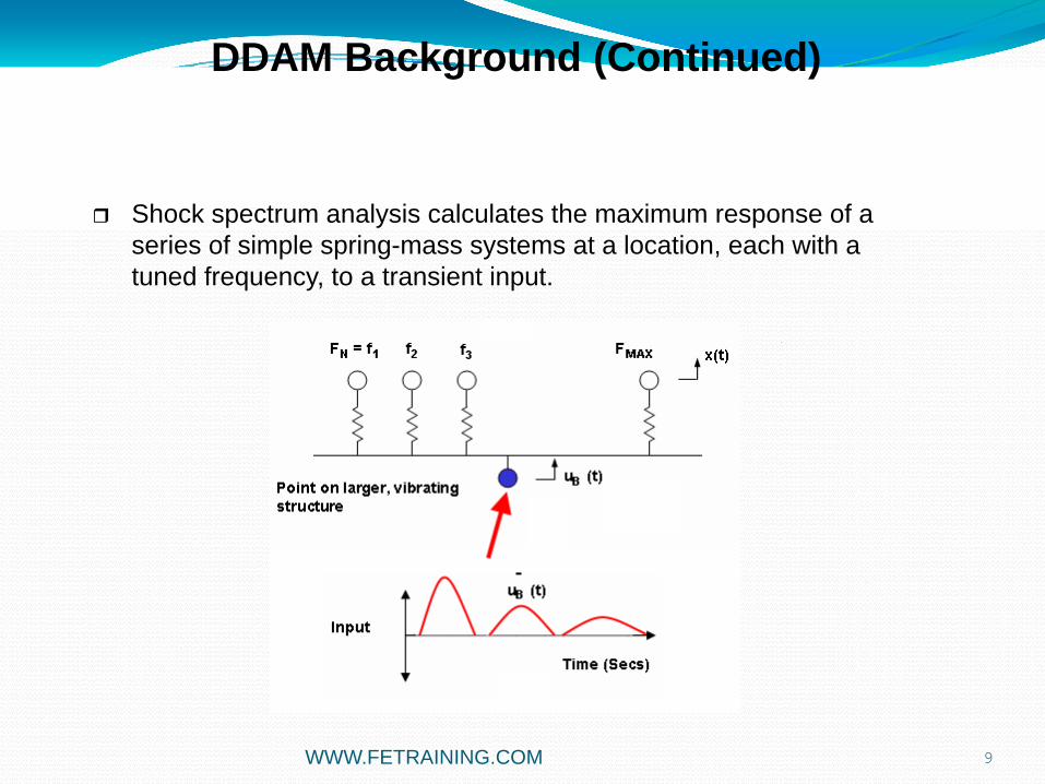
Shock spectrum analysis calculates the maximum response of a series of simple spring-mass systems at a location, each with a tuned frequency, to a transient input.
DDAM Background (Continued)
WWW.FETRAINING.COM

10
The overall plot of maximum response plotted against frequency is called a response spectrum.
The response spectrum is then used to evaluate the peak responses of equipment at the location
DDAM Background (Continued)
WWW.FETRAINING.COM
11
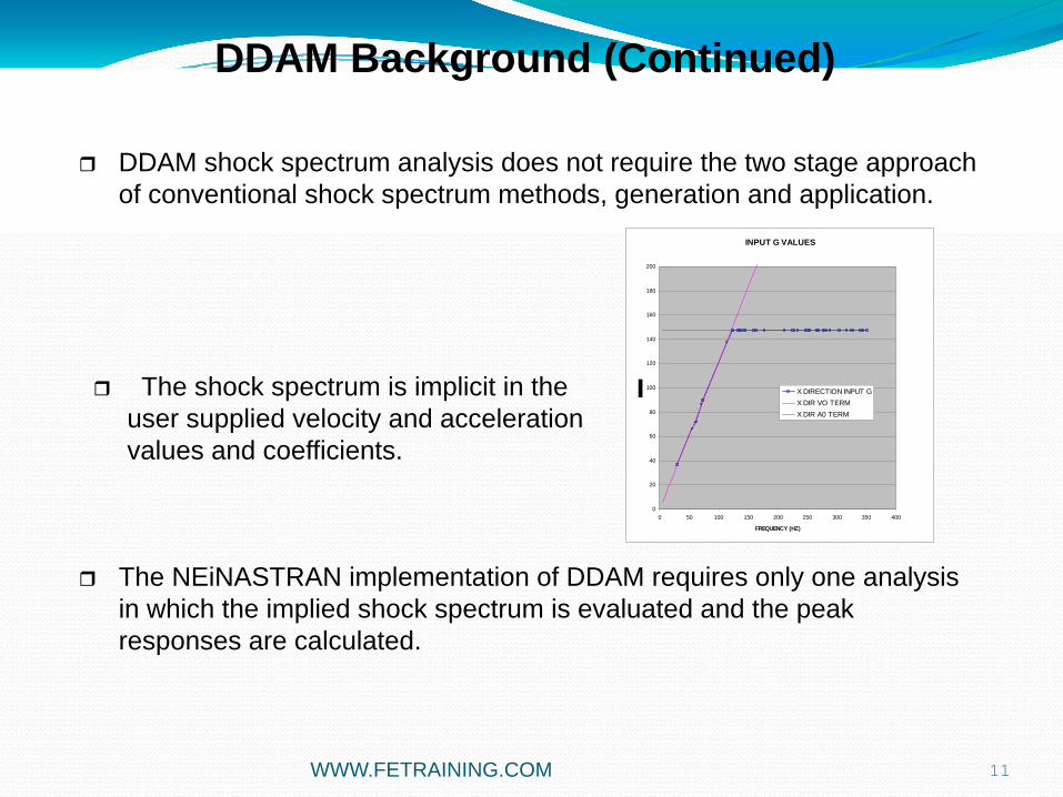
DDAM shock spectrum analysis does not require the two stage approach of conventional shock spectrum methods, generation and application.
The NEiNASTRAN implementation of DDAM requires only one analysis in which the implied shock spectrum is evaluated and the peak responses are calculated.
DDAM Background (Continued)
INPUT G VALUES
0
20
40
60
80
100
120
140
160
180
200
0 50 100 150 200 250 300 350 400
FREQUENCY (HZ)
X DIRECTION INPUT GX DIR VO TERMX DIR A0 TERM
The shock spectrum is implicit in the user supplied velocity and acceleration values and coefficients.
WWW.FETRAINING.COM

12
There is an interaction between the equipment being shock loaded and its structure. This change in spectrum is often called the spectrum-dipeffect. It is similar to soil structure interaction in seismic analysis, where the free field accelerations are greater than those with a very heavy structure present.
In the analysis of shipboard equipment the spectrum-dip effect has a pronounced effect on the shock spectra that an individual equipment may experience. The coefficients included in the DDAM analysis allow for the influence of equipment location and orientation. The spectrum is also reduced to account for the mass of the equipment.
In a conventional shock spectra analysis no interaction is assumed between the base structure and the component.
DDAM Background (Continued)
WWW.FETRAINING.COM
13
Dynamic Design Analysis (DDAM) Procedure
The first step in the DDAM procedure is to calculate the natural frequencies of the system.
The Eigenvalues ( Natural frequencies) and Eigenvectors (Mode Shapes) are extracted using the Lanczos or Subspace eigensolver.
The Participation Factors and Modal Effective Weight are calculated for each Mode and each direction (x, y and z) automatically.
WWW.FETRAINING.COM
14
Once the Modal Effective Weight and Frequency are known for each mode, the shock spectrum INPUT acceleration can be calculated (each modal frequency in each direction).The ship type, orientation and spectrum-dip effect on the input acceleration are included via the coefficients defined on the DDAMDAT entry.
The peak acceleration input for each mode can be derived from the user defined Acceleration Coefficients, Velocity Coefficients or Minimum Acceleration. The criteria used are reported in the output.
The shock responses are calculated until the target Effective weight is reached, or until all modes are exhausted.The peak velocities and displacements at each mode are derived from the accelerations.All other output quantities such as Stress and Force can be derived from the peak displacements.
DDAM Analysis Procedure (Continued)
WWW.FETRAINING.COM

15
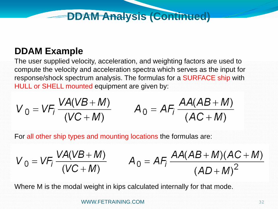
The user supplied velocity, acceleration, and weighting factors are used to compute the velocity and acceleration spectra which serves as the input for response/shock spectrum analysis. The formulas for a SURFACE ship with HULL or SHELL mounted equipment are given by:
For all other ship types and mounting locations the formulas are:
Where M is the modal weight in kips calculated internally for that mode.
Input Acceleration calculation
DDAM Analysis (Continued)
WWW.FETRAINING.COM

16
Input Acceleration calculation
DDAM Analysis (Continued)
INPUT G VALUES
0
20
40
60
80
100
120
140
160
180
200
0 50 100 150 200 250 300 350 400
FREQUENCY (HZ)
X DIRECTION INPUT GX DIR VO TERMX DIR A0 TERM
Aeq = V0 * Fi
WWW.FETRAINING.COM
17
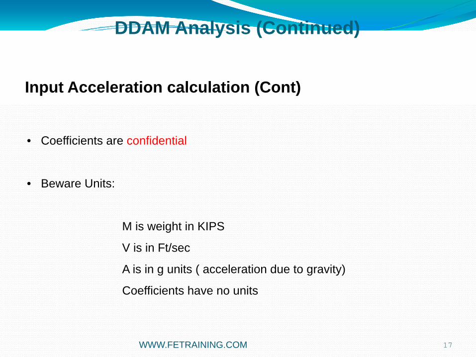
• Coefficients are confidential
• Beware Units:
M is weight in KIPS
V is in Ft/sec
A is in g units ( acceleration due to gravity)
Coefficients have no units
DDAM Analysis (Continued)
Input Acceleration calculation (Cont)
WWW.FETRAINING.COM

18
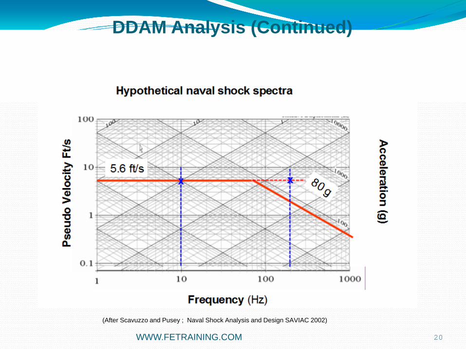
Hypothetical naval shock spectraSurface Ship, Hull mounted equipment
(After Scavuzzo and Pusey ; Naval Shock Analysis and Design SAVIAC 2002)
DDAM Analysis (Continued)
AF1 = 1.0 AA = 50.0AB = 40.0AC = 10.0
VF1 = 1.0VA = 4.0VB = 30.0VC = 10.0
M = 40 kips (40,000 lb)
Vanilla Coefficients
V0 = 5.6 ft/sA0 = 80.0 g
WWW.FETRAINING.COM

19
Hypothetical naval shock spectraSurface Ship, Hull mounted equipment
DDAM Analysis (Continued)
V0 = 5.6 ft/s
This must be converted to equivalent acceleration:
Aeq = V * Modal Frequency (rad/s) g = 32.2 ft/s^2g
If Modal Frequency = 62.83 rad/s (10Hz) Aeq = 10.9 g
A0 is larger so Aeq is used ( VELOCITY DRIVEN)
If Modal Frequency = 1256 rad/s (200Hz) Aeq = 218 g
Aeq is larger so A0 is used (ACCELERATION DRIVEN)
WWW.FETRAINING.COM
(After Scavuzzo and Pusey ; Naval Shock Analysis and Design SAVIAC 2002)
20
DDAM Analysis (Continued)
WWW.FETRAINING.COM
(After Scavuzzo and Pusey ; Naval Shock Analysis and Design SAVIAC 2002)

21
Hypothetical naval shock spectraSurface Ship, Hull mounted equipment
DDAM Analysis (Continued)
Consider two extremes:
1. Modal Mass is very low
A0 = 200 gV0 = 12 ft/s
2. Modal Mass is very high
A0 = 50 gV0 = 4 ft/s
Input Acceleration will be in this range, dependent on Modal Mass
WWW.FETRAINING.COM
(After Scavuzzo and Pusey ; Naval Shock Analysis and Design SAVIAC 2002)

22
12 ft/s
4 ft/s
Hypothetical naval shock spectra
Frequency (Hz)
Pseu
do V
eloc
ity F
t/sA
cceleration (g)
Low Modal Mass
High Modal Mass
DDAM Analysis (Continued)
WWW.FETRAINING.COM
(After Scavuzzo and Pusey ; Naval Shock Analysis and Design SAVIAC 2002)

23
The shock response for each mode is computed as follows:
where:
DDAM Analysis Procedure (Continued)
WWW.FETRAINING.COM
24
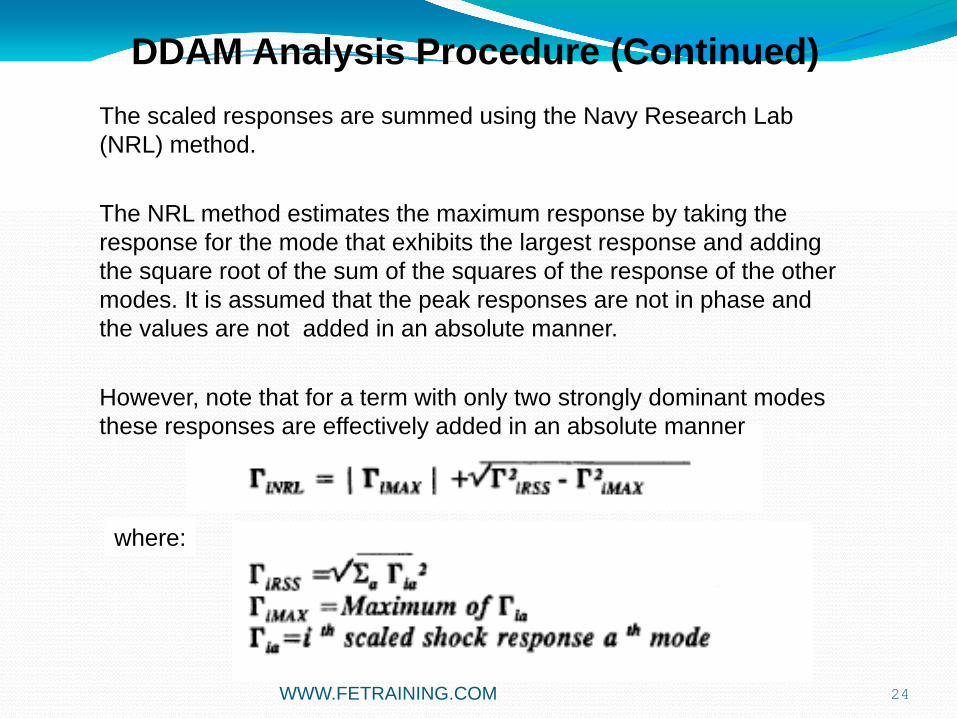
The scaled responses are summed using the Navy Research Lab (NRL) method.
The NRL method estimates the maximum response by taking the response for the mode that exhibits the largest response and adding the square root of the sum of the squares of the response of the other modes. It is assumed that the peak responses are not in phase and the values are not added in an absolute manner.
However, note that for a term with only two strongly dominant modes these responses are effectively added in an absolute manner
where:
DDAM Analysis Procedure (Continued)
WWW.FETRAINING.COM

DDAM Analysis
Dynamic Design Analysis (DDAM) Summary
A form of shock spectrum analysis
User supplied shock coefficients
Performs Shock excitation calculations
Generates Shock Spectrum data
Applies modal summation techniques
Optional Modal cutoff percentage
Modes ordered by Participation Factor or Mode Number
25WWW.FETRAINING.COM

26
MODAL EFFECTIVE MASS THEORY
DDAM BACKGROUND.
SIMPLE DDAM ANALYSIS
MODAL DATABASE USAGE
BRACKET DDAM ANALYSIS – CHASING MODAL EFFECTIVE MASS
MODESET USAGE
ENGINE DECK CRADLE - LARGE SCALE ANALYSIS
DDAM STRESSES
AGENDA
WWW.FETRAINING.COM

DDAM Analysis (Continued)
DDAM Example
As an example we will use the cantilever beam shown.
It is desired to find the response of the beam when subjected to the specified DDAM shock environment.
27
Forward
Athwart
WWW.FETRAINING.COM

DDAM Analysis (Continued)
$$ MODAL SOLUTION.$SOL MODALCEND$TITLE = INSTALLATION TEST CASESUBTITLE = DDAM ANALYSIS OF A 3-D CANTILEVER BEAM$DISPLACEMENT = ALLVELOCITY = ALLACCELERATION = ALLSTRESS = ALL$SUBCASE 1SPC = 1METHOD = 1DDAM = 1$BEGIN BULK
28
The analysis is set up like a typical normal modes analysis with the exception of the DDAM Case Control command and DDAMDATBulk Data entry.
The DDAM command initiates a shock spectrum solution sequence and references the DDAMDATentry.
Note that only one Subcase is defined, but multiple input directions can be applied on the DDAMDAT entry, each spawning a Subcase automatically.
DDAM Example
WWW.FETRAINING.COM

DDAM Analysis (Continued)
$$ DDAM COEFFICIENTS AND ANALYSIS PARAMETERS.$DDAMDAT, 1, 0.25, 0.5, 1., 0.25, 0.5, 1., 10.,, 20., 50., 10., 37.5, 6., , SURFACE, DECK,, 123, 1, 3, 386.4, 6., 80.
29
The sequence shock directions are applied
Definition of Fore-Aftand vertical components
Weight-mass conversionfactor
Min. acceleration.If computed value less than this then Min. value is used
coefficients on velocity and accelerations
DDAM Example
Type of ship,Position of component
Target Effective Mass
The DDAMDATentry contains the shock environment in coefficient form and the analysis control settings.
The analysis control settings specify shock directions and their labels and the modal mass cutoff percentage at which shock excitation calculations cease.
In our example analysis all three shock directions are requested though only the results of the third (vertical direction) will be presented.WWW.FETRAINING.COM

DDAM Analysis (Cont.)
User supplied shock coefficients on the DDAMDAT entry
1 2 3 4 5 6 7 8 9 10
DDAMDAT SID VF1 VF2 VF3 AF1 AF2 AF3 VA
VB VC AA AB AC AD STYPE LTYPE
DIRSEQ FADIR VDIR GCF MINACC CUTOFF MTYPE
DDAMDAT 10 0.25 0.5 1.0 0.25 0.50 1.0 10.0
20.0 50.0 10.0 45.5 6.5 15.0 SURFACE HULL
3 1 100.0
VFi and AFi are directional coefficients
Ax and Vx are non-directional coefficients
DDAM Example
30WWW.FETRAINING.COM

DDAM Analysis (Continued)
$$ DDAM COEFFICIENTS AND ANALYSIS PARAMETERS.$DDAMDAT, 1, 0.25, 0.5, 1., 0.25, 0.5, 1., 10.,, 20., 50., 10., 37.5, 6., , SURFACE, DECK,, 123, 1, 3, 386.4, 6., 80.
31
The sequence shock directions are applied
Definition of Fore-Aftand vertical components
DDAM Example
Directional Coefficients
• NEiNASTRAN does not update the coefficient order, to avoid storing this data in the code
• The user must re-order as appropriateWWW.FETRAINING.COM
32
The user supplied velocity, acceleration, and weighting factors are used to compute the velocity and acceleration spectra which serves as the input for response/shock spectrum analysis. The formulas for a SURFACE ship with HULL or SHELL mounted equipment are given by:
For all other ship types and mounting locations the formulas are:
Where M is the modal weight in kips calculated internally for that mode.
DDAM Example
DDAM Analysis (Continued)
WWW.FETRAINING.COM

33
The acceleration term to be used in the shock factor calculation is assessed from the minimum values of the direct acceleration and the acceleration derived from the velocity.
If accelerations generated are less than MINACC, the MINACC value will be used.
The source of the acceleration is reported in the output.
The modal mass cutoff percentage is percentage of total mass at which modal processing ceases.
DDAM analysis requires that only a percentage (typically 80%) of the total modal mass needs to be included in the NRL sum.
The material type specified in the MTYPE field only affects the output labels and is not used in the analysis.
The character variable PLASTIC does not indicate or initiate nonlinear analysis.
DDAM Analysis (Continued)
WWW.FETRAINING.COM

DDAM Analysis (Continued)
R E A L E I G E N V A L U E S
MODE EIGENVALUE RADIANS CYCLES GENERALIZED GENERALIZED ORTHOGONALITY ERROR NUMBER MASS STIFFNESS LOSS MEASURE
1 1.576987E+05 3.971130E+02 6.320250E+01 1.000000E+00 1.576987E+05 0.000000E+00 1.227248E-14 2 3.943060E+06 1.985714E+03 3.160362E+02 1.000000E+00 3.943060E+06 1.155646E-14 2.955895E-14 3 6.037523E+06 2.457137E+03 3.910655E+02 1.000000E+00 6.037523E+06 1.688713E-15 8.159152E-16 4 4.616942E+07 6.794808E+03 1.081427E+03 1.000000E+00 4.616942E+07 1.782905E-14 2.261833E-16 5 1.509607E+08 1.228661E+04 1.955474E+03 1.000000E+00 1.509607E+08 3.964347E-16 3.785877E-15 6 1.724843E+08 1.313333E+04 2.090234E+03 1.000000E+00 1.724843E+08 2.377492E-16 1.090117E-16 7 4.574813E+08 2.138881E+04 3.404135E+03 1.000000E+00 4.574813E+08 1.310584E-15 8.413792E-17 8 9.514420E+08 3.084545E+04 4.909206E+03 1.000000E+00 9.514420E+08 2.255649E-28 2.619714E-15 9 9.864355E+08 3.140757E+04 4.998670E+03 1.000000E+00 9.864355E+08 1.676146E-28 1.797256E-16
10 1.154409E+09 3.397659E+04 5.407542E+03 1.000000E+00 1.154409E+09 5.764565E-17 1.163198E-15 11 1.839977E+09 4.289495E+04 6.826943E+03 1.000000E+00 1.839977E+09 1.976612E-16 3.595590E-14 12 3.045140E+09 5.518279E+04 8.782614E+03 1.000000E+00 3.045140E+09 7.285839E-17 3.824739E-12 13 4.312754E+09 6.567156E+04 1.045195E+04 1.000000E+00 4.312754E+09 2.561294E-16 3.568461E-11 14 4.468211E+09 6.684468E+04 1.063866E+04 1.000000E+00 4.468211E+09 1.517765E-16 1.616015E-10 15 5.695423E+09 7.546803E+04 1.201111E+04 1.000000E+00 5.695423E+09 1.257675E-17 6.912539E-10 16 8.422989E+09 9.177684E+04 1.460674E+04 1.000000E+00 8.422989E+09 4.477803E-19 1.857973E-15 17 1.143875E+10 1.069521E+05 1.702195E+04 1.000000E+00 1.143875E+10 1.422968E-19 7.019080E-08 18 2.263472E+10 1.504484E+05 2.394460E+04 1.000000E+00 2.263472E+10 3.950147E-19 7.909201E-16 19 2.466459E+10 1.570496E+05 2.499522E+04 1.000000E+00 2.466459E+10 2.002828E-17 9.592725E-06 20 4.219548E+10 2.054154E+05 3.269287E+04 1.000000E+00 4.219548E+10 1.442139E-18 5.547834E-16
34
We have requested a normal modes analysis with 20 modes recovered.The range is 63Hz to 32,693Hz.We would expect that the higher modes will be insignificant in the shock response.
DDAM Example
WWW.FETRAINING.COM

DDAM Analysis (Continued)
D D A M A N A L Y S I S D A T A D E F I N I T I O N
DDAM DATA SET = 1
SHIP TYPE = SURFACE MOUNTING LOCATION = DECK MATERIAL TYPE = ELASTIC SUMMATION METHOD = NRL
TOTAL MASS = 5.176000E-04 TOTAL WEIGHT = 2.000006E-01 CONVERSION FACTOR = 3.864000E+02
35
The listing shows a summary of the user specified analysis control settings
DDAM Example
WWW.FETRAINING.COM

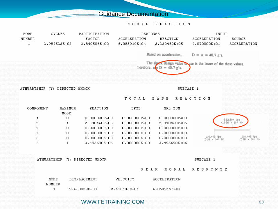
DDAM Analysis (Continued)VERTICAL (Z) DIRECTED SHOCK SUBCASE 3
M O D A L E F F E C T I V E W E I G H T
MODE CYCLES PARTICIPATION MODAL CUMULATIVE NUMBER FACTOR WEIGHT PERCENT WEIGHT PERCENT
2 3.160362E+02 -1.777455E-02 1.220771E-01 61.0383 1.220771E-01 61.0383 5 1.955474E+03 9.873827E-03 3.767108E-02 18.8355 1.597482E-01 79.8738 10 5.407542E+03 5.776554E-03 1.289362E-02 6.4468 1.726418E-01 86.3206
MASS AVAILABLE = 92.8737 PERCENT MASS USED = 86.3206 PERCENT
36
This listing shows part of the output for Subcase 3, the vertical shock loading.Shows the significant individual and cumulative modal weights through the calculated frequencies. In our case we have achieved the target modal weight of 80% after 10 modes, i.e. 5408 Hz. Note that we were very close to target after 5 modes (1955 Hz).All 20 modes contribute 92.9% weight.The cumulative modal weight should be checked in each shock direction to verify the required percentage is achieved. Failure to meet the required modal weight requires either increasing the number of desired modes or the frequency range on the EIGRL Bulk Data entry and rerunning the model.
WWW.FETRAINING.COM
DDAM Analysis (Continued)
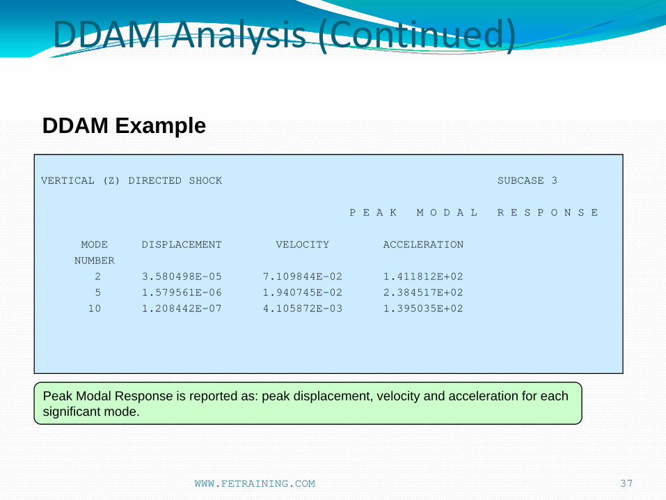
VERTICAL (Z) DIRECTED SHOCK SUBCASE 3
P E A K M O D A L R E S P O N S E
MODE DISPLACEMENT VELOCITY ACCELERATION NUMBER
2 3.580498E-05 7.109844E-02 1.411812E+02 5 1.579561E-06 1.940745E-02 2.384517E+02
10 1.208442E-07 4.105872E-03 1.395035E+02
37
Peak Modal Response is reported as: peak displacement, velocity and acceleration for each significant mode.
DDAM Example
WWW.FETRAINING.COM

DDAM Analysis (Continued)
VERTICAL (Z) DIRECTED SHOCK SUBCASE 3
M O D A L R E A C T I O N
MODE CYCLES PARTICIPATION RESPONSE INPUT NUMBER FACTOR ACCELERATION REACTION ACCELERATION SOURCE
2 3.160362E+02 -1.777455E-02 1.411812E+02 -2.509431E+00 2.055612E+01 VELOCITY 5 1.955474E+03 9.873827E-03 2.384517E+02 2.354430E+00 6.249967E+01 ACCELERATION 10 5.407542E+03 5.776554E-03 1.395035E+02 8.058497E-01 6.249989E+01 ACCELERATION
38
Input Acceleration = input acceleration in g units derived from DDAMDAT coefficientsSource = the criteria that gave highest input acceleration
acceleration – directly from acceleration coefficientsvelocity – derived from velocity coefficientsminimum g – derived from defined minimum g level
Participation Factor (PFACTOR) determines the contribution of each modeResponse Acceleration = peak modal accel = input accel * PFACTOR in fundamental unitsResponse Reaction = total dynamic forces on the masses = PFACTOR * peak modal accel
DDAM Example
WWW.FETRAINING.COM

DDAM Analysis (Continued)
VERTICAL (Z) DIRECTED SHOCK SUBCASE 3
T O T A L B A S E R E A C T I O N
COMPONENT MAXIMUM REACTION SRSS NRL SUM MODE
1 8 0.000000E+00 0.000000E+00 0.000000E+00 2 1 0.000000E+00 0.000000E+00 0.000000E+00 3 2 2.509431E+00 2.488521E+00 4.997952E+00 4 0 0.000000E+00 0.000000E+00 0.000000E+00 5 2 1.831502E+01 5.077361E+00 2.339238E+01 6 1 0.000000E+00 0.000000E+00 0.000000E+00
39
For each direction:Reaction = Mode with maximum dynamic force and value of the forceSRSS = The SRSS of contributions of the remainder of the modes in that directionNRL SUM = The NRL summation of the Peak reaction and the SRSS of the remainder in each direction
DDAM Example
WWW.FETRAINING.COM

DDAM Analysis (Continued)
40
VERTICAL (Z) DIRECTED SHOCK SUBCASE 3
D I S P L A C E M E N T V E C T O R
GRID COORDINATE T1 T2 T3 R1 R2 R3
ID ID
2 0 0.000000E+00 0.000000E+00 6.518836E-05 0.000000E+00 1.254091E-04 0.000000E+00
3 0 0.000000E+00 0.000000E+00 2.410175E-04 0.000000E+00 2.214736E-04 0.000000E+00
4 0 0.000000E+00 0.000000E+00 4.988605E-04 0.000000E+00 2.900596E-04 0.000000E+00
5 0 0.000000E+00 0.000000E+00 8.126876E-04 0.000000E+00 3.349217E-04 0.000000E+00
- - - - - - - - - - - - - - - - - - - - - - - - - - - - - - - - - - - - - - - - - - - - - - - - - - - - -
10 0 0.000000E+00 0.000000E+00 2.771175E-03 0.000000E+00 4.969525E-04 0.000000E+00
11 0 0.000000E+00 0.000000E+00 3.269731E-03 0.000000E+00 4.996089E-04 0.000000E+00
MAXIMUM DISPLACEMENT MAGNITUDE = 3.269731E-03 AT GRID 11
MAXIMUM ROTATION MAGNITUDE = 4.996089E-04 AT GRID 11
Peak displacements are calculated from the peak accelerations and combined using the NRL method
DDAM Example
WWW.FETRAINING.COM

DDAM Analysis (Continued)
41
VERTICAL (Z) DIRECTED SHOCK SUBCASE 3
F O R C E S I N B A R E L E M E N T S
ELEMENT DISTANCE BENDING MOMENT SHEAR FORCE AXIAL TORQUE
ID PLANE 1 PLANE 2 PLANE 1 PLANE 2 FORCE
1 0.0000 1.874176E-14 2.339238E+01 1.019053E-14 4.997952E+00 0.000000E+00 0.000000E+00
0.0000 9.916143E-15 1.843065E+01 1.019053E-14 4.997952E+00 0.000000E+00 0.000000E+00
2 0.0000 9.525158E-15 1.842811E+01 8.604592E-15 4.851512E+00 0.000000E+00 0.000000E+00
0.0000 2.826726E-15 1.386419E+01 8.604592E-15 4.851512E+00 0.000000E+00 0.000000E+00
- - - - - - - - - - - - - - - - - - - - - - - - - - - - - - - - - - - - - - - - - - - - - - - - - - - - -
9 0.0000 9.467554E-15 2.981920E+00 5.254982E-15 2.021816E+00 0.000000E+00 0.000000E+00
0.0000 4.301747E-15 9.762868E-01 5.254982E-15 2.021816E+00 0.000000E+00 0.000000E+00
10 0.0000 4.076723E-15 9.660734E-01 4.114474E-15 9.606903E-01 0.000000E+00 0.000000E+00
0.0000 0.000000E+00 5.994315E-03 4.114474E-15 9.606903E-01 0.000000E+00 0.000000E+00
Forces are calculated in a similar manner
DDAM Example
WWW.FETRAINING.COM
DDAM Analysis (Continued)
42
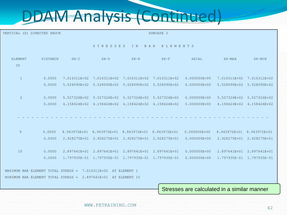
VERTICAL (Z) DIRECTED SHOCK SUBCASE 3
S T R E S S E S I N B A R E L E M E N T S
ELEMENT DISTANCE SX-C SX-D SX-E SX-F AXIAL SX-MAX SX-MIN
ID
1 0.0000 7.016311E+02 7.016311E+02 7.016311E+02 7.016311E+02 0.000000E+00 7.016311E+02 7.016311E+02
0.0000 5.528090E+02 5.528090E+02 5.528090E+02 5.528090E+02 0.000000E+00 5.528090E+02 5.528090E+02
2 0.0000 5.527326E+02 5.527326E+02 5.527326E+02 5.527326E+02 0.000000E+00 5.527326E+02 5.527326E+02
0.0000 4.158424E+02 4.158424E+02 4.158424E+02 4.158424E+02 0.000000E+00 4.158424E+02 4.158424E+02
- - - - - - - - - - - - - - - - - - - - - - - - - - - - - - - - - - - - - - - - - - - - - - - - - - - - -
9 0.0000 8.943972E+01 8.943972E+01 8.943972E+01 8.943972E+01 0.000000E+00 8.943972E+01 8.943972E+01
0.0000 2.928275E+01 2.928275E+01 2.928275E+01 2.928275E+01 0.000000E+00 2.928275E+01 2.928275E+01
10 0.0000 2.897641E+01 2.897641E+01 2.897641E+01 2.897641E+01 0.000000E+00 2.897641E+01 2.897641E+01
0.0000 1.797935E-01 1.797935E-01 1.797935E-01 1.797935E-01 0.000000E+00 1.797935E-01 1.797935E-01
MAXIMUM BAR ELEMENT TOTAL STRESS = 7.016311E+02 AT ELEMENT 1
MINIMUM BAR ELEMENT TOTAL STRESS = 2.897641E+01 AT ELEMENT 10
Stresses are calculated in a similar manner
WWW.FETRAINING.COM
DDAM Analysis (Continued)
43
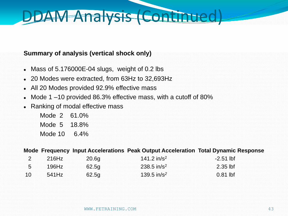
Summary of analysis (vertical shock only)
Mass of 5.176000E-04 slugs, weight of 0.2 lbs20 Modes were extracted, from 63Hz to 32,693HzAll 20 Modes provided 92.9% effective massMode 1 –10 provided 86.3% effective mass, with a cutoff of 80%Ranking of modal effective mass
Mode 2 61.0%Mode 5 18.8%Mode 10 6.4%
Mode Frequency Input Accelerations Peak Output Acceleration Total Dynamic Response2 216Hz 20.6g 141.2 in/s2 -2.51 lbf5 196Hz 62.5g 238.5 in/s2 2.35 lbf
10 541Hz 62.5g 139.5 in/s2 0.81 lbf
WWW.FETRAINING.COM

DDAM Analysis (Continued)
44
Modes 2, 5 and 10 are the only modes to show displacement in the vertical plane
Mode 2
Mode 5 Mode 10
Summary of analysis (vertical shock only)
WWW.FETRAINING.COM

DDAM Analysis (Continued)
45
Summary of analysis (vertical shock only)
T O T A L B A S E R E A C T I O N
COMPONENT MAXIMUM REACTION SRSS NRL SUM MODE
1 8 0.000000E+00 0.000000E+00 0.000000E+002 1 0.000000E+00 0.000000E+00 0.000000E+003 2 2.509431E+00 2.488521E+00 4.997952E+00 4 0 0.000000E+00 0.000000E+00 0.000000E+005 2 1.831502E+01 5.077361E+00 2.339238E+01 6 1 0.000000E+00 0.000000E+00 0.000000E+00
The Total Base Reaction Table confirms there are no contributions from other component directions other than 3 and 5 (vertical and pitch) and that mode 2 response is maximum in both.
The total vertical reaction is 5 lbf, 50% from the peak mode value and 50% from the SRSS of the other modes.
The total pitch reaction is 23.4 lbf -in , 18.3 lbf-in from the peak, 5.1 lbf -in from the SRSS of the other modes
WWW.FETRAINING.COM

46
Peak Bending Moment Diagram
Maximum value 23 lbf-in at root
Peak Shear Force Diagram
Maximum value 5 lbf at root
NEiNASTRANModeler Results Subcase 3
Summary of analysis (vertical shock only)
DDAM Analysis (Continued)
WWW.FETRAINING.COM

47
MODAL EFFECTIVE MASS THEORY
DDAM BACKGROUND.
SIMPLE DDAM ANALYSIS
MODAL DATABASE USAGE
BRACKET DDAM ANALYSIS – CHASING MODAL EFFECTIVE MASS
MODESET USAGE
ENGINE DECK CRADLE - LARGE SCALE ANALYSIS
DDAM STRESSES
AGENDA
WWW.FETRAINING.COM

48
Modal Database Usage
• Simple Modal Data save and re-use option• Contains Modes, Frequencies, PF’s, MEM’s – all modal data• Very big savings in CPU time are possible with all Modal based
response methods as the main burden is always the calculation of the Modal data
• Parameter:
MODALDATABASE, optionwhere option is
DELETE = Modal database is deletedSTORE = Modal database is storedFETCH = Modal database is retrieved(default is DELETE)
The data is stored in a file called jobname.mdb (may be specified using MODALDATFILE directive)
WWW.FETRAINING.COM
49
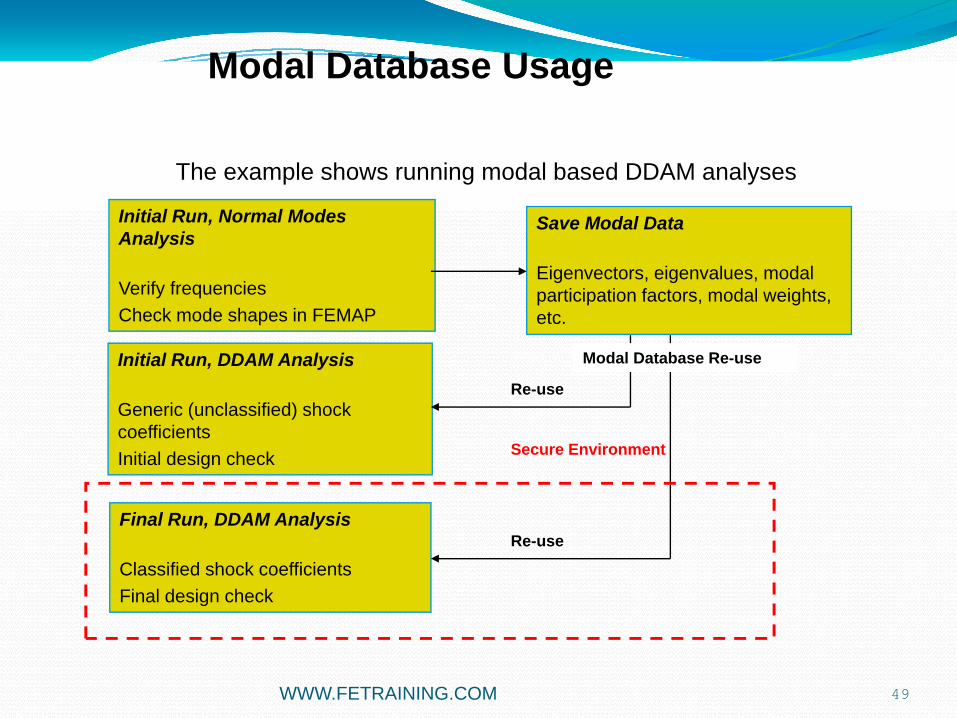
The example shows running modal based DDAM analyses
Initial Run, Normal Modes Analysis
Verify frequenciesCheck mode shapes in FEMAP
Save Modal Data
Eigenvectors, eigenvalues, modal participation factors, modal weights, etc.
Initial Run, DDAM Analysis
Generic (unclassified) shock coefficientsInitial design check
Re-use
Final Run, DDAM Analysis
Classified shock coefficientsFinal design check
Re-use
Secure Environment
Modal Database Re-use
Modal Database Usage
WWW.FETRAINING.COM

Multi Phase DDAM
50
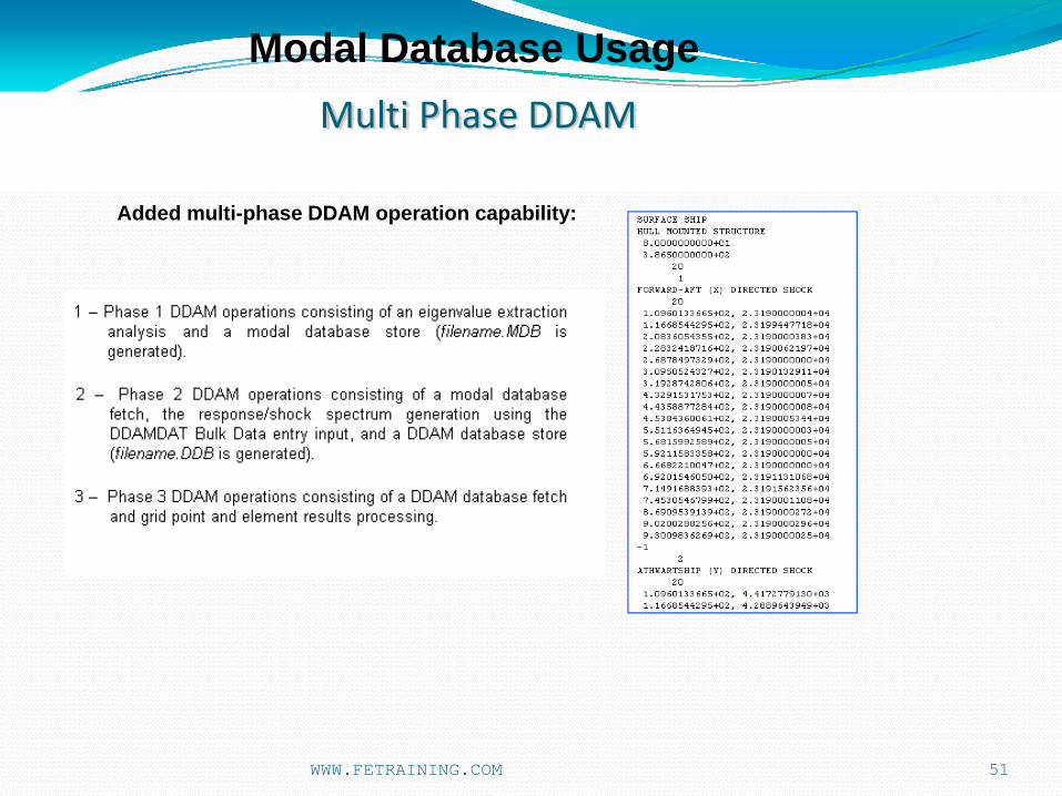
Added multi-phase DDAM operation capability:
A multi-phase DDAM operation capability has been added to improve productivity in a mixed secured and unsecured environment.
The integrity of the DDAM coefficients is essential and this feature preserves this, while allowing the user more flexibility.
A new parameter controls which phase of a DDAM analysis is to be run.
This allows an initial (phase 1) DDAM checkout run to be carried out in an unsecured environment; the run can then be restarted in a secure environment using the Modal database (phase 2).
A new DDAM database has been created which allows storage of the shock input G versus frequency spectra calculated from the DDAM coefficients.
This is the only file which needs to be exported from the secure environment, and is easily verifiable for content. The final phase, phase 3 , is then to calculate the DDAM responses in the unsecured environment.
Modal Database Usage
WWW.FETRAINING.COM
Multi Phase DDAM
51
Added multi-phase DDAM operation capability:
Modal Database Usage
WWW.FETRAINING.COM

Multi Phase DDAM
52
Added multi-phase DDAM operation capability:
PHASE 1Initial Run, Normal Modes Analysis
Verify frequenciesCheck mode shapes in FEMAP
PHASE 2DDAM Automatic Analysis re-start
Input Classified shock coefficients
Re-use
PHASE 3 DDAM Automatic Analysis re-start
Full DDAM Response calculations
Re-use
Secure Environment
Modal Database .MDB
(E-vectors, PF, MEM etc.)
DDAM Database .DDB
(Input Accn vs Freq)
MODESET if required
Modal Database Usage
WWW.FETRAINING.COM

WWW.FETRAINING.COM 53
Enhanced DDAM output –shock curve
Enhanced DDAM output for shock curve ( Acceleration vs Frequency):
Initialization setting in the Editor
Auxiliary output to .BDF file

54
Shock curves available in .FNO file
Can be read into FEMAP for plotting and export
Enhanced DDAM output –shock curve
WWW.FETRAINING.COM

55
INPUT G VALUES
0
20
40
60
80
100
120
140
160
180
200
0 50 100 150 200 250 300 350 400
FREQUENCY (HZ)
X DIRECTION INPUT GX DIR VO TERMX DIR A0 TERM
Calculated Input shock curve versus V0 and A0 calculation
Enhanced DDAM output –shock curve
WWW.FETRAINING.COM

56
MODAL EFFECTIVE MASS THEORY
DDAM BACKGROUND.
SIMPLE DDAM ANALYSIS
MODAL DATABASE USAGE
BRACKET DDAM ANALYSIS – CHASING MODAL EFFECTIVE MASS
MODESET USAGE
ENGINE DECK CRADLE - LARGE SCALE ANALYSIS
DDAM STRESSES
AGENDA
WWW.FETRAINING.COM

WWW.FETRAINING.COM 57
For a simple model, a few modes are adequate to represent > 80% Effective Mass.
In a complex model like the one shown here we have many more DOF’s and many more available modes.
How many modes are required to achieve 80% Effective Mass?
vert
athwart
f/a
Bulkhead attachment
Effective Mass

DIRECTION TOTAL MASS MODAL EFF MASS PERCENT
1 Fore Aft 50.74 34.20 67.402 Athwart 50.74 10.85 21.383 Vertical 50.74 46.33 91.31
58
Results of a DDAM analysis with 100 Modes
The Frequency range is given by Mode 1 at 13.9 Hz to Mode 100 at 267 Hz
The vertical direction is well represented. Inspection of the modes shows that the cantilever bending of each web dominates.
Fore Aft direction modes are rich in back panel bending.
Athwartship modes are limited to swaying/shearing modes of the webs
WWW.FETRAINING.COM

59
T1 Effective Mass
0.1
1
10
100
1 6 11 16 21 26 31 36 41 46 51 56 61 66 71 76 81 86 91 96 101
T2 Effective Mass
0.1
1
10
1 6 11 16 21 26 31 36 41 46 51 56 61 66 71 76 81 86 91 96 101
T3 Effective Mass
0.1
1
10
100
1 8 15 22 29 36 43 50 57 64 71 78 85 92 99
The dominant Modes are shown in red
The distribution of Effective Mass for each direction can be seen on the log/lin scale
Effective Mass (Continued)
T1 Effective Mass
T3 Effective MassT2 Effective Mass
WWW.FETRAINING.COM

T2 Cumulative Effective Mass
0
2
4
6
8
10
12
0 20 40 60 80 100 120
T3 Cumulative Effective Mass
30
32
34
36
38
40
42
44
46
48
50
0 10 20 30 40 50 60 70 80 90 100
T1 Cumulative Effective Mass
0
5
10
15
20
25
30
35
40
0 20 40 60 80 100 120
60
Another way to look at it...
Effective Mass
T1 Cumulative Effective Mass
T2 Cumulative Effective Mass T3 Cumulative Effective Mass
WWW.FETRAINING.COM

61
What the Modes Look Like
Mode 1 dominates in the vertical direction as each web bends
Mode 1
WWW.FETRAINING.COM

62
Mode 46 dominates in the athwart direction as the back plate is distorted in bending
Mode 46
What the Modes Look Like (Continued)
WWW.FETRAINING.COM
63
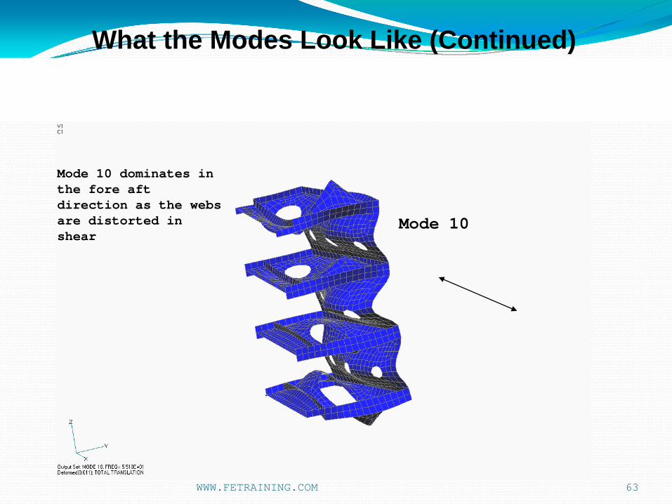
Mode 10 dominates in the fore aft direction as the webs are distorted in shear
Mode 10
What the Modes Look Like (Continued)
WWW.FETRAINING.COM

64
Mode 2 Mode 4
Mode 5Mode 11
Other Dominant Modes
WWW.FETRAINING.COM

65
Mode 18 Mode 19
Mode 38
Other Dominant Modes (Continued)
WWW.FETRAINING.COM

66
DDAM ANALYSIS OF A DECK MOUNTED STRUCTURE ON A SURFACE SHIP
FORWARD-AFT (X) DIRECTED SHOCK SUBCASE 1
M O D A L E F F E C T I V E W E I G H T
MODE CYCLES PARTICIPATION MODAL CUMULATIVE NUMBER FACTOR WEIGHT PERCENT WEIGHT PERCENT 46 1.431045E+02 5.650084E+00 1.233841E+04 62.9119 1.233841E+04 62.9119 10 5.510104E+01 8.530688E-01 2.812662E+02 1.4341 1.261968E+04 64.3460 40 1.256555E+02 -5.315739E-01 1.092136E+02 0.5569 1.272889E+04 64.9029 18 7.438546E+01 4.891139E-01 9.246331E+01 0.4715 1.282136E+04 65.3744 11 5.952799E+01 3.548671E-01 4.867220E+01 0.2482 1.287003E+04 65.6225 31 1.079753E+02 -3.448361E-01 4.595947E+01 0.2343 1.291599E+04 65.8569 43 1.357897E+02 -3.143244E-01 3.818613E+01 0.1947 1.295417E+04 66.0516 37 1.232318E+02 -2.934976E-01 3.329344E+01 0.1698 1.298747E+04 66.2213 4 3.986048E+01 -2.397935E-01 2.222410E+01 0.1133 1.300969E+04 66.3346 51 1.534952E+02 2.377015E-01 2.183802E+01 0.1113 1.303153E+04 66.4460 96 2.557597E+02 -2.289278E-01 2.025566E+01 0.1033 1.305178E+04 66.5493 2 3.226531E+01 2.279338E-01 2.008016E+01 0.1024 1.307186E+04 66.6517 56 1.605290E+02 -2.071893E-01 1.659145E+01 0.0846 1.308846E+04 66.7363 47 1.474133E+02 1.992237E-01 1.534022E+01 0.0782 1.310380E+04 66.8145 14 6.732457E+01 1.856066E-01 1.331485E+01 0.0679 1.311711E+04 66.8824
--- (DATA CONTINUES) ---
Formal Numbers from the DDAM Analysis
Fore - Aft
WWW.FETRAINING.COM

67
M O D A L E F F E C T I V E W E I G H T
MODE CYCLES PARTICIPATION MODAL CUMULATIVE NUMBER FACTOR WEIGHT PERCENT WEIGHT PERCENT 10 5.510104E+01 -2.355943E+00 2.145255E+03 10.9384 2.145255E+03 10.9384 11 5.952799E+01 -1.247536E+00 6.015278E+02 3.0671 2.746783E+03 14.0055 18 7.438546E+01 -1.198498E+00 5.551678E+02 2.8307 3.301951E+03 16.8362 4 3.986048E+01 7.313262E-01 2.067149E+02 1.0540 3.508666E+03 17.8902 2 3.226531E+01 -7.159604E-01 1.981196E+02 1.0102 3.706785E+03 18.9004 46 1.431045E+02 6.491813E-01 1.628851E+02 0.8305 3.869670E+03 19.7309 100 2.666761E+02 3.760780E-01 5.466448E+01 0.2787 3.924335E+03 20.0097 14 6.732457E+01 -3.588405E-01 4.976824E+01 0.2538 3.974103E+03 20.2634 6 4.682373E+01 -3.539971E-01 4.843383E+01 0.2470 4.022537E+03 20.5104 98 2.579296E+02 -3.434915E-01 4.560175E+01 0.2325 4.068139E+03 20.7429 16 6.944919E+01 2.627076E-01 2.667440E+01 0.1360 4.094813E+03 20.8789 20 7.943116E+01 2.350775E-01 2.135854E+01 0.1089 4.116172E+03 20.9878 39 1.253063E+02 -1.805027E-01 1.259264E+01 0.0642 4.128764E+03 21.0520 81 2.243995E+02 1.415805E-01 7.747412E+00 0.0395 4.136512E+03 21.0915 8 5.115970E+01 -1.406313E-01 7.643871E+00 0.0390 4.144156E+03 21.1305 13 6.648926E+01 -1.396246E-01 7.534826E+00 0.0384 4.151690E+03 21.1689 80 2.168292E+02 -1.173435E-01 5.321909E+00 0.0271 4.157012E+03 21.1960
--- (DATA CONTINUES) ---
Athwart
Formal Numbers from the DDAM Analysis (Continued)
WWW.FETRAINING.COM

68
M O D A L E F F E C T I V E W E I G H T
MODE CYCLES PARTICIPATION MODAL CUMULATIVE NUMBER FACTOR WEIGHT PERCENT WEIGHT PERCENT
1 1.398901E+01 5.918081E+00 1.353665E+04 69.0216 1.353665E+04 69.0216 5 4.399860E+01 1.883970E+00 1.371821E+03 6.9947 1.490847E+04 76.0163 19 7.682255E+01 -1.738562E+00 1.168234E+03 5.9567 1.607671E+04 81.9730 38 1.245205E+02 8.206635E-01 2.603033E+02 1.3273 1.633701E+04 83.3002 48 1.475497E+02 6.772558E-01 1.772780E+02 0.9039 1.651429E+04 84.2041 12 6.315209E+01 -6.491054E-01 1.628471E+02 0.8303 1.667714E+04 85.0345 71 1.989739E+02 -5.210544E-01 1.049339E+02 0.5350 1.678207E+04 85.5695 82 2.250989E+02 -4.529868E-01 7.930867E+01 0.4044 1.686138E+04 85.9739 49 1.515428E+02 -4.510805E-01 7.864255E+01 0.4010 1.694002E+04 86.3749 88 2.369557E+02 -4.424514E-01 7.566250E+01 0.3858 1.701568E+04 86.7607 35 1.202262E+02 -4.396944E-01 7.472251E+01 0.3810 1.709041E+04 87.1417 92 2.419596E+02 -4.190874E-01 6.788264E+01 0.3461 1.715829E+04 87.4878
--- (DATA CONTINUES) ---
Vertical
Formal Numbers from the DDAM Analysis (Continued)
WWW.FETRAINING.COM
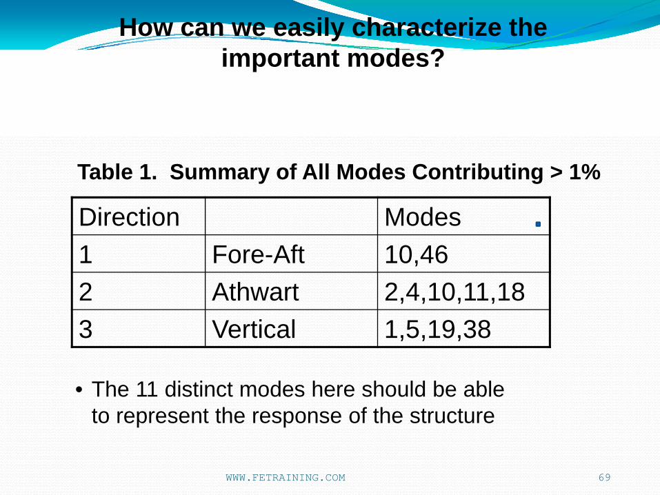
Direction Modes1 Fore-Aft 10,462 Athwart 2,4,10,11,183 Vertical 1,5,19,38
69
• The 11 distinct modes here should be able to represent the response of the structure
Table 1. Summary of All Modes Contributing > 1%
How can we easily characterize the important modes?
WWW.FETRAINING.COM

Direction Modes1 Fore Aft 46,10,40,18,11,31,43,37,4,512 Athwart 10,11,18,4,2,46,100,14,6,983 Vertical 1,5,19,38,48,12,71,82,49,88
70
• The 25 distinct modes ensure a good spread of modes from each direction. It will avoid elimination of directions with low total effective mass.
Table 2. Summary of Modes Contributing Top 10 Effective Mass in Each Direction
How can we easily characterize the important modes?
WWW.FETRAINING.COM

71
MODAL EFFECTIVE MASS THEORY
DDAM BACKGROUND.
SIMPLE DDAM ANALYSIS
MODAL DATABASE USAGE
BRACKET DDAM ANALYSIS – CHASING MODAL EFFECTIVE MASS
MODESET USAGE
ENGINE DECK CRADLE - LARGE SCALE ANALYSIS
DDAM STRESSES
AGENDA
WWW.FETRAINING.COM

NEiNASTRANimplementation now allows simplification of modes used in DDAM (and all Modal Response Analysis) using these ideas
Options:
Automatically select top n effective modes in each direction. (User defines n). The result is as Table 1.
Automatically select all modes contributing > xx % Effective Mass in any direction. (user defines xx). The result is as Table 2.
User Picks individual modes to be used in the analysis (requires user skill and verification)
72
MODESET Enhancement
WWW.FETRAINING.COM

The user is able to select the modes that will be included in a DDAM analysis (or any modal solution)This is via the following options:
User specifies a collection of mode id’s to be used on a SET entry ( less than or equal to no of modes on EIGRL)
User specifies the top N modes for each direction sorted by modal contribution (default 20 or max modes on EIGRL card).
User specifies a maximum % contribution to modal effective mass. Only those modes that equal or exceed this value will be used.
The options 2 and 3 allow for quick specification of modes in a general case and will avoid the need for manual inspection of all of the modes.
73
MODESET Enhancement
WWW.FETRAINING.COM
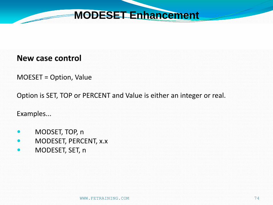
New case control
MOESET = Option, Value
Option is SET, TOP or PERCENT and Value is either an integer or real.
Examples...
MODSET, TOP, nMODESET, PERCENT, x.xMODESET, SET, n
74
MODESET Enhancement
WWW.FETRAINING.COM

This enhancement to selectively choose Modes for a DDAM analysis was requested by NAVSEA for a different purpose.
But is very applicable to general usage with large complex models.
75
MODESET Enhancement
WWW.FETRAINING.COM

76
MODESET Enhancement
Added EXCLUDE and INCLUDE options to the MODESET Case Control command:
Primarily for use in DDAM analysis, but with applications in all response analysis, this feature allows a user to quickly isolate a few important modes from a large number of modes and test the response.
Combined with the Modal Database restart feature, it becomes a fast and powerful investigation tool.
Added an EXCLUDE option to the MODESET Case Control command. EXCLUDE allows the specification of a SET of modes that are to be excluded from the extracted set.
Also, added an INCLUDE option which is functionally the same as SET.
WWW.FETRAINING.COM

DDAM analysis models will get bigger and bigger.
Large models versus modes required to achieve target Effective Mass will continue to be debated.
MODESET is very powerful, particularly when used with the Modal Database
77
MODESET Enhancement
WWW.FETRAINING.COM

78
MODAL EFFECTIVE MASS THEORY
DDAM BACKGROUND.
SIMPLE DDAM ANALYSIS
MODAL DATABASE USAGE
BRACKET DDAM ANALYSIS – CHASING MODAL EFFECTIVE MASS
MODESET USAGE
3010 SDOF EXAMPLE
ENGINE DECK CRADLE - LARGE SCALE ANALYSIS
DDAM STRESSES
AGENDA
WWW.FETRAINING.COM

7979
• Original DDAM research work and development at NRL in the early 1960’s by O’Hara et al.
• Original NAVSEA report version released in May 1976
• formalized original work
• all calculations carried out by hand
• The ‘bible’ for DDAM analysis is current NAVSEA report 9098-LP-000-3010 Rev.1 Sept. 1995
• Scope of Analysis had increased significantly over this period. 1995 document reflected this and introduced discussion on:
• Closely Spaced Modes
• Multi-Directional Response
• Dynamic Reduction Techniques
• Mode Selection Criteria
Guidance Documentation
WWW.FETRAINING.COM

8080
• However modeling techniques presented in 1995 were very different from current methodologies
• Lumped mass representation
• Allowed simple ‘manual’ assumptions to be made
• 50% base mass contribution is prime example
• Eliminated local modes due to distributed mass
• Bar stiffness representation
• Frames, girders etc. all heavily idealized
• Removed many local modes present in shell (or solid!) idealizations
• Small Models
• Small number of modes
• DDAM criteria of high contributing mass (MEM) readily achievable
Guidance Documentation
WWW.FETRAINING.COM

8181
• Two FEM examples available in current NAVSEA report 9098-LP-000-3010 Rev.1 Sept. 1995
• Simple cabinet on foundation – single degree of freedom
• Equipment rack multi degree of freedom
• Stated purpose is to illustrate some concepts, not to provide examples of best practice
Guidance Documentation
WWW.FETRAINING.COM
8282
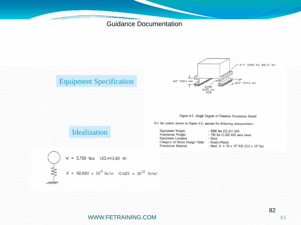
Equipment Specification
Idealization
Guidance Documentation
WWW.FETRAINING.COM

8383
Equipment SpecificationIdealization
Guidance Documentation
WWW.FETRAINING.COM

WWW.FETRAINING.COM 84
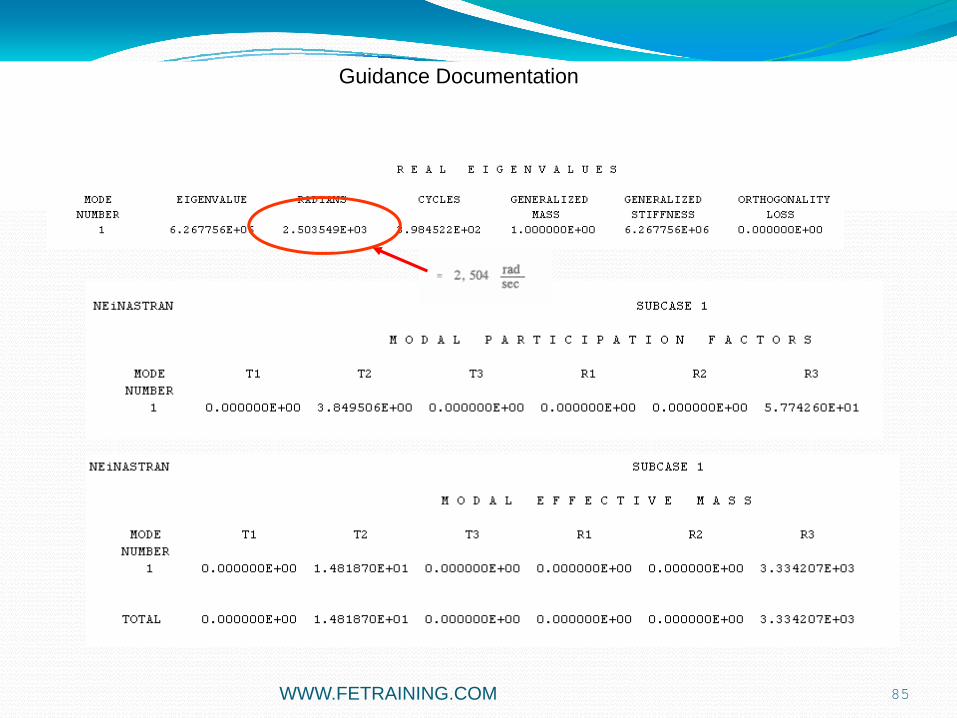
Guidance Documentation
WWW.FETRAINING.COM 85
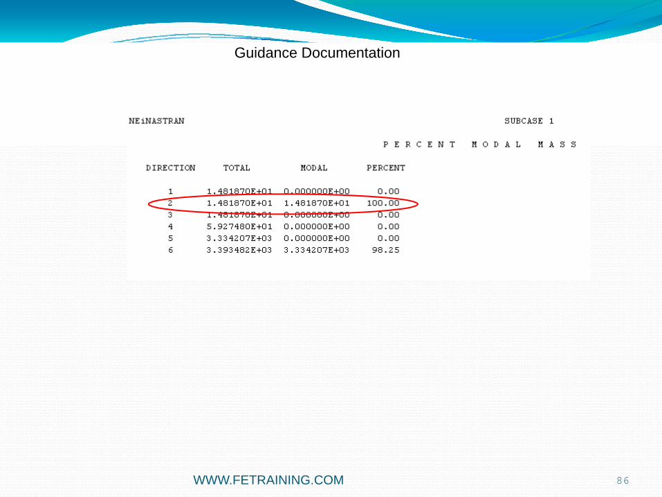
Guidance Documentation
WWW.FETRAINING.COM 86
Guidance Documentation

WWW.FETRAINING.COM 87
Guidance Documentation
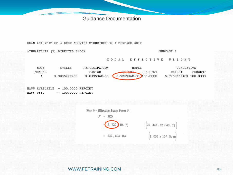
WWW.FETRAINING.COM 88
Guidance Documentation
WWW.FETRAINING.COM 89
Guidance Documentation

WWW.FETRAINING.COM 90
Guidance Documentation
91
MODAL EFFECTIVE MASS THEORY
DDAM BACKGROUND.
SIMPLE DDAM ANALYSIS
MODAL DATABASE USAGE
BRACKET DDAM ANALYSIS – CHASING MODAL EFFECTIVE MASS
MODESET USAGE
RACK EXAMPLE
ENGINE DECK CRADLE - LARGE SCALE ANALYSIS
DDAM STRESSES
AGENDA
WWW.FETRAINING.COM

92
RACK EXAMPLE
WWW.FETRAINING.COM

93
MODAL EFFECTIVE MASS THEORY
DDAM BACKGROUND.
SIMPLE DDAM ANALYSIS
MODAL DATABASE USAGE
BRACKET DDAM ANALYSIS – CHASING MODAL EFFECTIVE MASS
MODESET USAGE
3010 SDOF EXAMPLE
ENGINE DECK CRADLE - LARGE SCALE ANALYSIS
DDAM STRESSES
AGENDA
WWW.FETRAINING.COM
94
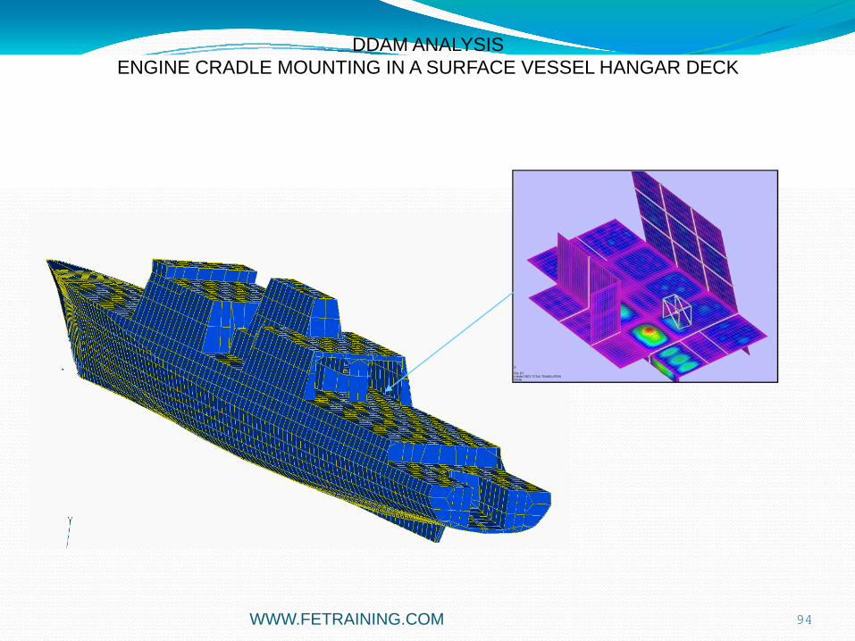
DDAM ANALYSISENGINE CRADLE MOUNTING IN A SURFACE VESSEL HANGAR DECK
WWW.FETRAINING.COM

95
DDAM ANALYSISENGINE CRADLE MOUNTING IN A SURFACE VESSEL HANGAR DECK
• DDAM analysis carried out on Cradle Mounting
• ‘Vanilla’ coefficients used
• Accelerations Measured
• Three levels of idealization used
• Cradle in Isolation
• Cradle mounted on local deck structure
• Cradle assembled in Hangar structure
• Comparison of Modeling Accuracy and DDAM results in each case
• How much backing structure should be modeled?
WWW.FETRAINING.COM

96
CRADLE
LOCAL DECKHANGAR
The three levels of idealization used
WWW.FETRAINING.COM

97
CRADLE IN ISOLATION
Lumped mass 4000 lbs
Runners assumedfully fixed to deck
Rigid interconnection to frame points
WWW.FETRAINING.COM

98
FORWARD-AFT (X) DIRECTED SHOCK SUBCASE 1
MODE CYCLES PARTICIPATION RESPONSE INPUT
NUMBER FACTOR ACCELERATION REACTION ACCELERATION SOURCE
2 8.330861E+01 3.307479E+00 1.832549E+04 6.061118E+04 1.433538E+01 VELOCITY
ATHWARTSHIP (Z) DIRECTED SHOCK SUBCASE 2
MODE CYCLES PARTICIPATION RESPONSE INPUT
NUMBER FACTOR ACCELERATION REACTION ACCELERATION SOURCE
1 1.067862E+01 3.313163E+00 7.683225E+03 2.545578E+04 6.000000E+00 MINIMUM-G
VERTICAL (Y) DIRECTED SHOCK SUBCASE 3
MODE CYCLES PARTICIPATION RESPONSE INPUT
NUMBER FACTOR ACCELERATION REACTION ACCELERATION SOURCE
8 1.031109E+02 -3.250511E+00 2.446288E+04 -7.951686E+04 1.947181E+01 VELOCITY
Modal Input and Response from DDAM
• Each dominant mode drives a shock response direction
• No coupling
CRADLE IN ISOLATION
WWW.FETRAINING.COM

99
P E R C E N T M O D A L M A S S
DIRECTION TOTAL MODAL PERCENT
1 1.128501E+01 1.104935E+01 97.91
2 1.128501E+01 1.088630E+01 96.47
3 1.128501E+01 1.098078E+01 97.30
4 3.065230E+06 2.984946E+06 97.38
5 9.623747E+07 9.364481E+07 97.31
6 9.859524E+07 9.515650E+07 96.51
FORWARD-AFT (X)MODE 2
ATHWARTSHIP (Z)MODE 8
VERTICAL (Y)MODE 1
CRADLE IN ISOLATION• High Modal Mass achieved with 15 modes, little noise
WWW.FETRAINING.COM

100
FORWARD-AFT (X)PEAK ACCN 10,734 IN/S^227.8g
ATHWARTSHIP (Z)PEAK ACCN 2,799 IN/S^27.3g
VERTICAL (Y)PEAK ACCN 12,916 IN/S^233.43g
DDAM peak accelerations
CRADLE IN ISOLATION
WWW.FETRAINING.COM

WWW.FETRAINING.COM 101
CRADLE PLUS LOCAL DECK
Cradle
Deck
Support Beams
All Deck Boundaries Simply Supported

WWW.FETRAINING.COM 102
P E R C E N T M O D A L M A S S
DIRECTION TOTAL MODAL PERCENT
1 1.393104E+01 1.133629E+01 81.37 2 1.393104E+01 1.309284E+01 93.98 3 1.393104E+01 1.132716E+01 81.31 4 3.714471E+06 3.130420E+06 84.28 5 1.188631E+08 9.659414E+07 81.27 6 1.217118E+08 1.140065E+08 93.67
CRADLE PLUS LOCAL DECK
• High Modal Mass achieved little noise
• 25 Modes would be sufficient to achieve 80%
• frequencies significantly lowered
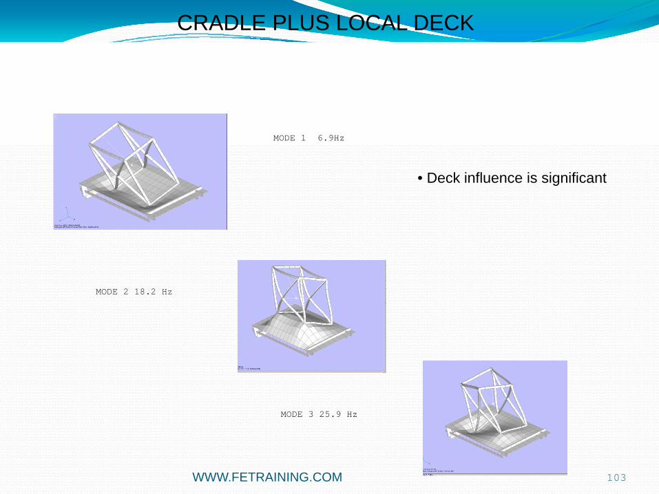
WWW.FETRAINING.COM 103
MODE 1 6.9Hz
MODE 2 18.2 Hz
MODE 3 25.9 Hz
• Deck influence is significant
CRADLE PLUS LOCAL DECK
WWW.FETRAINING.COM 104
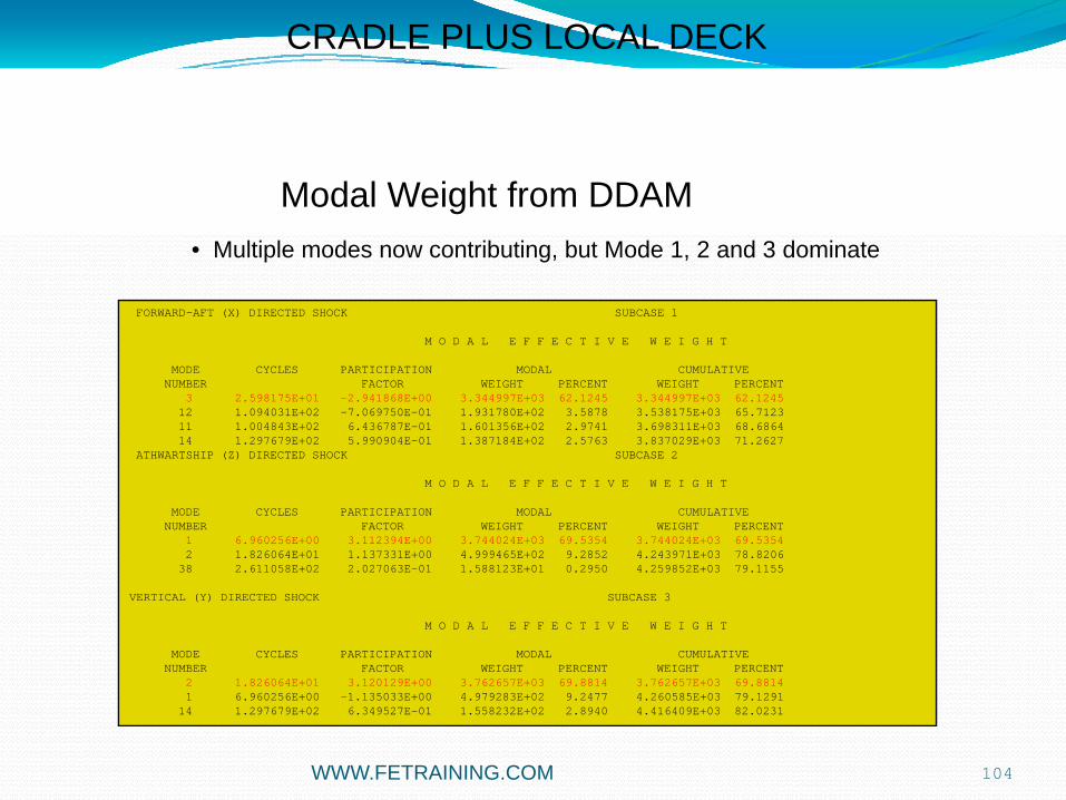
FORWARD-AFT (X) DIRECTED SHOCK SUBCASE 1
M O D A L E F F E C T I V E W E I G H T
MODE CYCLES PARTICIPATION MODAL CUMULATIVE NUMBER FACTOR WEIGHT PERCENT WEIGHT PERCENT
3 2.598175E+01 -2.941868E+00 3.344997E+03 62.1245 3.344997E+03 62.124512 1.094031E+02 -7.069750E-01 1.931780E+02 3.5878 3.538175E+03 65.7123 11 1.004843E+02 6.436787E-01 1.601356E+02 2.9741 3.698311E+03 68.6864 14 1.297679E+02 5.990904E-01 1.387184E+02 2.5763 3.837029E+03 71.2627
ATHWARTSHIP (Z) DIRECTED SHOCK SUBCASE 2
M O D A L E F F E C T I V E W E I G H T
MODE CYCLES PARTICIPATION MODAL CUMULATIVE NUMBER FACTOR WEIGHT PERCENT WEIGHT PERCENT
1 6.960256E+00 3.112394E+00 3.744024E+03 69.5354 3.744024E+03 69.53542 1.826064E+01 1.137331E+00 4.999465E+02 9.2852 4.243971E+03 78.8206
38 2.611058E+02 2.027063E-01 1.588123E+01 0.2950 4.259852E+03 79.1155
VERTICAL (Y) DIRECTED SHOCK SUBCASE 3
M O D A L E F F E C T I V E W E I G H T
MODE CYCLES PARTICIPATION MODAL CUMULATIVE NUMBER FACTOR WEIGHT PERCENT WEIGHT PERCENT
2 1.826064E+01 3.120129E+00 3.762657E+03 69.8814 3.762657E+03 69.88141 6.960256E+00 -1.135033E+00 4.979283E+02 9.2477 4.260585E+03 79.1291
14 1.297679E+02 6.349527E-01 1.558232E+02 2.8940 4.416409E+03 82.0231
Modal Weight from DDAM• Multiple modes now contributing, but Mode 1, 2 and 3 dominate
CRADLE PLUS LOCAL DECK

WWW.FETRAINING.COM 105
• Modal Effective Mass charts clearly show this
CRADLE PLUS LOCAL DECK
WWW.FETRAINING.COM 106
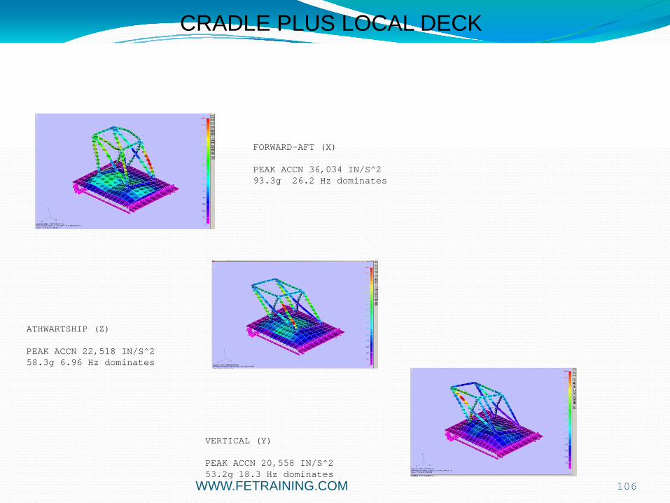
FORWARD-AFT (X)
PEAK ACCN 36,034 IN/S^293.3g 26.2 Hz dominates
ATHWARTSHIP (Z)
PEAK ACCN 22,518 IN/S^258.3g 6.96 Hz dominates
VERTICAL (Y)
PEAK ACCN 20,558 IN/S^253.2g 18.3 Hz dominates
CRADLE PLUS LOCAL DECK

107
• Formal DDAM approach is probably to use only ½ of local deck mass plus full cradle mass
• parametric study carried out
• small frequency shift, drop in MEM
10.5
11
11.5
12
12.5
13
0 50 100 150 200 250 300 350 400
1/2 base massfull base mass1/4 base mass
CRADLE PLUS LOCAL DECK
Frequency (Hz)
Cum
ulat
ive
Eff
Mas
s
Mode 1 identical
WWW.FETRAINING.COM
108
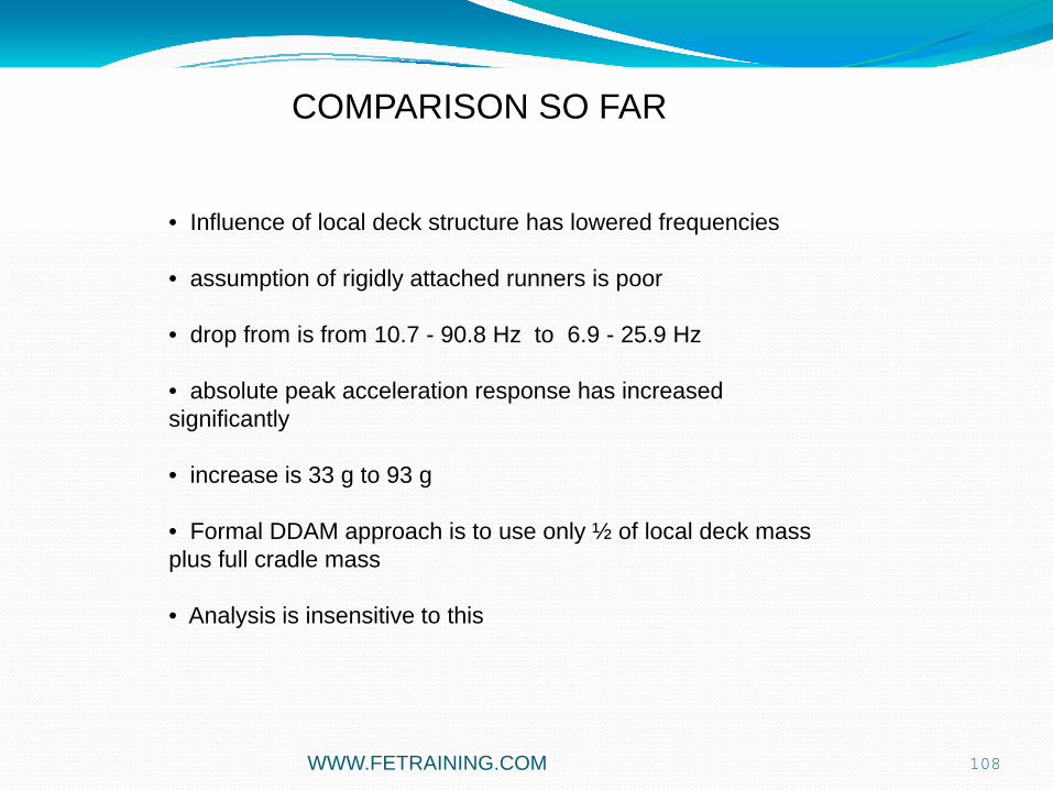
COMPARISON SO FAR
• Influence of local deck structure has lowered frequencies
• assumption of rigidly attached runners is poor
• drop from is from 10.7 - 90.8 Hz to 6.9 - 25.9 Hz
• absolute peak acceleration response has increased significantly
• increase is 33 g to 93 g
• Formal DDAM approach is to use only ½ of local deck mass plus full cradle mass
• Analysis is insensitive to this
WWW.FETRAINING.COM

109
CRADLE PLUS HANGAR
hull
Outer wallMain Deck
Inner walls
Cradle
bulkhead
WWW.FETRAINING.COM

110
FORWARD-AFT (X)
ATHWARTSHIP (Z)
VERTICAL (Y)
CRADLE PLUS HANGAR
• Peak Accelerations from DDAM
WWW.FETRAINING.COM

111
0%
5%
10%
15%
20%
25%
30%
35%
40%
45%
0 20 40 60 80 100 120
CRADLE PLUS HANGAR
Frequency Hz
Per
cent
age
Eff
Mod
al M
ass
• Modal Effective mass count 400 modes
WWW.FETRAINING.COM
112
0%
10%
20%
30%
40%
50%
60%
70%
80%
90%
0 50 100 150 200 250 300 350 400 450
CRADLE PLUS HANGAR
Frequency Hz
Per
cent
age
Eff
Mod
al M
ass
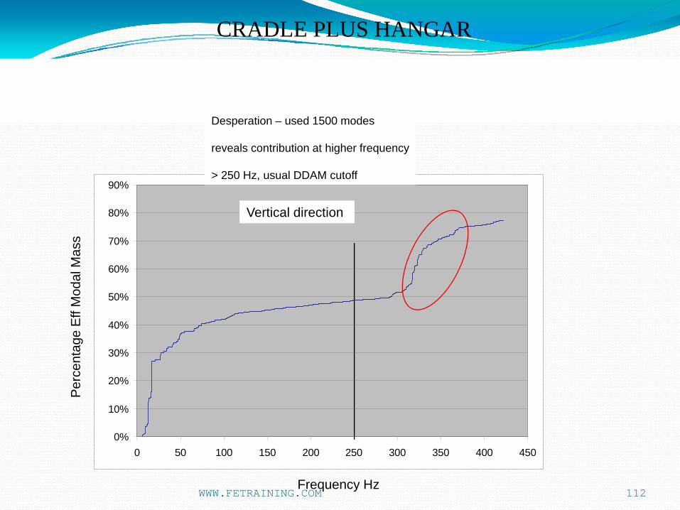
Desperation – used 1500 modes
reveals contribution at higher frequency
> 250 Hz, usual DDAM cutoff
Vertical direction
WWW.FETRAINING.COM

113
CRADLE PLUS HANGAR
Total Mode Numbers Used
Acc
eler
atio
n in
/s^2
‘MODESET’ feature used with modal database re-use makes multiple DDAM runs cheap and fast
Peak acceleration increases in 286 – 352 hz bandBase acceleration Increases in 352 – 422 hz band
Vertical direction Peak Cradle Acceleration
0
10000
20000
30000
40000
50000
60000
70000
80000
90000
0 200 400 600 800 1000 1200 1400 1600
peakbase
WWW.FETRAINING.COM

114
COMPARISON OF 3 IDEALIZATION LEVELS
• cradle model in isolation is too stiff at base
• cradle needs local deck structure for accurate natural frequency calculations
• low overall Modal effective Mass and low acceleration input for DDAM with hangar included unless very high mode count used
• increasing the complexity of the surrounding structure is a trade off
• more accurate frequencies
versus
• impossible to assign Modal Effective Mass to cradle contribution from overall response
• using mode count in DDAM as a filter re-using a modal database may be feasible
WWW.FETRAINING.COM
115
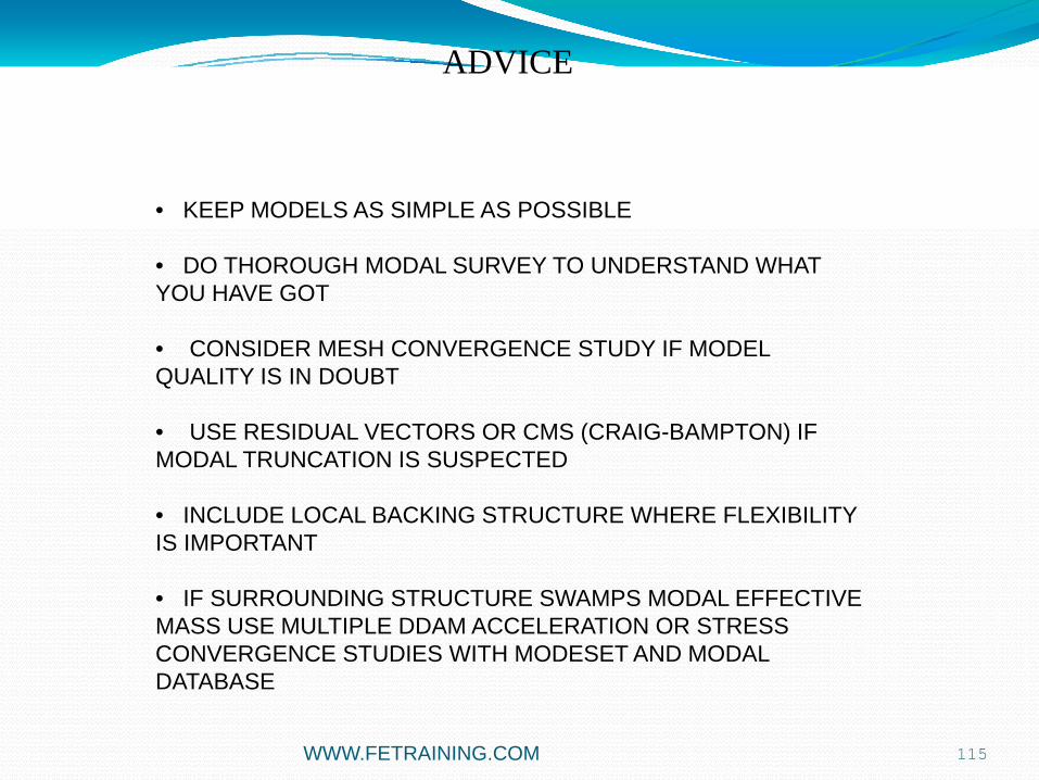
ADVICE
• KEEP MODELS AS SIMPLE AS POSSIBLE
• DO THOROUGH MODAL SURVEY TO UNDERSTAND WHAT YOU HAVE GOT
• CONSIDER MESH CONVERGENCE STUDY IF MODEL QUALITY IS IN DOUBT
• USE RESIDUAL VECTORS OR CMS (CRAIG-BAMPTON) IF MODAL TRUNCATION IS SUSPECTED
• INCLUDE LOCAL BACKING STRUCTURE WHERE FLEXIBILITY IS IMPORTANT
• IF SURROUNDING STRUCTURE SWAMPS MODAL EFFECTIVE MASS USE MULTIPLE DDAM ACCELERATION OR STRESS CONVERGENCE STUDIES WITH MODESET AND MODAL DATABASE
WWW.FETRAINING.COM

116
MODAL EFFECTIVE MASS THEORY
DDAM BACKGROUND.
DDAM PROCEDURE
SIMPLE DDAM ANALYSIS
MODAL DATABASE USAGE
BRACKET DDAM ANALYSIS – CHASING MODAL EFFECTIVE MASS
MODESET USAGE
ENGINE DECK CRADLE - LARGE SCALE ANALYSIS
DDAM STRESSES
AGENDA
WWW.FETRAINING.COM

117
DDAM STRESSES
Enhanced DDAM von Mises output stress in bars, beams and shells:As requested by the DDAM community, a new model parameter, EQVSTRESSTYPE now controls the von Mises stress calculation.
When set to 2 in linear solutions this will output membrane only von Mises stress in bar, beam, and shell elements.
The default setting of 0 will output membrane and bending von Mises stress.
The beam and bar von Mises calculation has been completely updated to include both transverse shear terms and the torsional shear stress term.
The effective section shear area is used to calculate the former. The latter uses either a user supplied effective torsional radius, or the appropriate dimension if the user inputs a section via a PBEAML or PBARL.
WWW.FETRAINING.COM

118
DDAM STRESSES
WWW.FETRAINING.COM

119
DDAM STRESSES
Enhanced DDAM von Mises output stress in bars, beams and shells:
WWW.FETRAINING.COM