dcu 305 r2 installation manual - auto-maskin
TRANSCRIPT

DCU 305 R2
Installation Manual
Diesel Engine Control Unit


DCU 305 R2 Installation Manual Document information • 1
Contents
Document information 3
Introduction 4
ABOUT THIS MANUAL 4
ABOUT THE DCU 305 R2 5
CLASSIFIED SYSTEM 5
SYSTEM OVERVIEW 6
CONFIGURATION OVERVIEW 7
TECHNICAL SPECIFICATIONS 7
Cable connection 9
GENERAL 9
GROUNDING 9
CONNECTION ORDER 9
POWER SUPPLY 10
START- AND STOP RELAY OUTPUTS 11
PICKUP SENSORS 11
SWITCH INPUT CHANNELS 12
ANALOGUE INPUT CHANNELS 13
MISCELLANEOUS CONNECTION 15
THE AUTOMATIC FUSES ON THE RK-66 R2 MODULE 17
BACKUP SYSTEM CONFIGURATION 17
BUILT-IN ALARMS 20
ADJUSTING THE LCD SCREEN 20
OVERSPEED TEST 22
Optional expansion modules 23
RELAY CARDS MK-6 AND MK-14 23
ANALOGUE CARD AK-6 26
Communication 28

2 • Document information DCU 305 R2 Installation Manual
PROTOCOL AND PIN-CONFIGURATION 28
MULTIDROP COMMUNICATION 29
RETRIEVE THE LOG TO A PC 29
Schematic Drawings 31
SAMPLE SCHEMATIC PAGE 1 31
SAMPLE SCHEMATIC PAGE 2 32
OPTIONAL RELAY CARD MK-6 33
OPTIONAL ANALOGUE CARD AK-6 34
CABLE SPECIFICATION 34
CABLE SPECIFICATION 35
WIRE TERMINAL TABLE, RK-66 R2 36
WIRE TERMINAL TABLE, RELAY CARD MK-6 AND MK-14 38
WIRE TERMINAL TABLE, ANALOGUE CARD AK-6 40
Appendix 41
ORDERING INFORMATION 41
DEC-TO-HEX TABLE 42

DCU 305 R2 Installation Manual Document information • 3
Document information
Document revisions
Date Revision
October 2002 Created
April 2004 Describes the new layout of the RK-66 R2 module
Copyright © Auto-Maskin AS, 2008
Information given in this document may change without prior notice. This document should not be copied without written permission from Auto-Maskin.
Title: DCU 305 R2 Installation Manual
Document article #: 06325
This Revision: January 2006
All trademarks acknowledged.
Related articles
§ DCU 305 R2 User’s Manual Article 06322
§ DCU 305 R2 Communication Manual. Article 06324
§ DCU 305 R2 Slave Panel. Article 75290
§ Rudolf R2 User’s Manual, English. Article 09326
§ Rudolf R2 Configuration Software. Article 75270
Auto-Maskin AS
Sophie Radichs Vei 7 N-2003 LILLESTRØM Norway Telephone (+47) 64 84 52 00 Telefax (+47) 64 84 52 12 E-mail [email protected] Internet www.auto-maskin.no

4 • Introduction DCU 305 R2 Installation Manual
Introduction
About this manual
This manual has been published primarily for professionals and qualified personnel. A person using this material is assumed to have basic knowledge in marine systems, and be able to carry out related electrical work.
Work on the boats low-tension circuit should only be carried out by qualified and experienced persons. Installation or work on the shore power equipment must only be carried out by electricians authorised to work with such installations.
It is the sole responsibility of the installer to ensure that the installation work is carried out in a satisfactorily manner, that it is operationally in good order, that the approved material and accessories are used and that the installation meet all applicable rules and regulations.
Note: Auto-Maskin continuously upgrades its products and reserves the right to make changes and improvements without prior notice.
All information in this manual is based upon information at the time of printing.
For updated information, please contact your dealer.
Assumptions
Control units
This document describes the DCU 305 R2 A and the DCU 305 R2 P control units. The DCU 305 R2 A is for auxiliary and emergency projects, whereas the DCU 305 R2 P is for propulsion engine projects.
Installation and operation of the two is similar, and this manual will point out the areas where they differ.
The two units will commonly be referred to as the Control Unit.
Voltages
When referring to voltages, we always assume DC-voltages. When referring to AC-voltages it will be mentioned explicitly.

DCU 305 R2 Installation Manual Introduction • 5
About the DCU 305 R2
The DCU 305 R2™ is an electronic control unit for control and monitoring of diesel engines used as propulsion engines or gensets.
Switches and senders from the engines are connected to the control unit on the wire terminal card RK-66 R2.
The DCU 305 R2 can be connected directly to a printer for output of all alarms and events, or it can be connected to a slave panel in a network of control units.
Each project is unique, which is why the DCU 305 R2 is customised using a configuration tool for Windows®, the Rudolf R2™ software.
Classified system
The DCU 305 R2 is classified by the following classification societies with their respective certificate number as follows:
Classification Society Certificate Number
Det norske Veritas, DnV A-7403, A-7404, A-7998
Lloyd’s Register of Shipping, LR 01/00050, SWC 0100001
Germanischer Lloyds, GL 42 526 – 02 HH
Bureau Veritas, BV 10747/A0 BV
Russian Maritime Register of Shipping, RS 01.013.262
Registro Italiano Navale, RINA MAC/38901CS1
American Bureau of Shipping, ABS 02-OS-8785-PTA
Other certificates and approvals may exist. Please see www.auto-maskin.no for latest update.

6 • Introduction DCU 305 R2 Installation Manual
System Overview
The control unit and the wire terminal card with cables make a complete genset monitoring system. Optional analogue cards and relay cards may be added to further enhance the functionality and flexibility.
The control unit is configured using a laptop PC with the configuration software Rudolf™ installed. The configuration can be printed and stored on disk.
RS232
Basic delivery
The DCU 305 R2 and the RK-66 R2 is part of the standard delivery that makes a complete system. The other items are optional.
Slave panels
The optional Slave Panels can be added any time, as it communicates directly towards the DCU 305 R2.
Several Slave panels can be used towards the same DCU 305 R2, or one Slave Panel can be used towards several DCU 305 R2 panels.
External
signals
RS-232Comli
RS-232Modbus
§ Project specific printout
§ Commissioning overview
§ Backup
§ Etc.
AK-6 Analog expansion
MK-14 Relay expansion
Genset
J1939 CAN
J1587
MK-6 Relay expansion
E615
Slave Panel 2
RSP 305 /
E615
Slave Panel 1
Modbus
Rudolf R2
Laptop PC with config. software
RK-66 R2 Wire terminal card
DCU 305 R2
Control Unit
Standard
Optional

DCU 305 R2 Installation Manual Introduction • 7
A PC with the Rudolf ™ parameter program is used to customize
the DCU 305 R2.
Configuration overview
The control unit is fully customised using the Rudolf™ configuration program. For safety reasons, no parameters are adjustable without using the configuration tool Rudolf.
No settings are necessary in the DCU 305 R2, nor in Rudolf, to connect and use the Rudolf program. Just connect the cable between your laptop PC and port P3 on the control unit.
Discussion of the Rudolf configuration software is beyond the scope of this manual. For more information, please see the Rudolf R2 User’s
Manual.
Technical Specifications
Part Value
Overall dimensions (1) 160 x 250 x 35mm (H x W x D)
Cut-out dimensions 146 x 230mm (H x W)
Overall depth inc. cables 105mm
Supply voltage (2) 24V smoothed, (18– 32VDC)
Power consumption (3) Typical: 500mA @ 24V DC
Maximum: 700mA @ 24VDC
Weight Control unit: 1250g
Protection level Front panel:
Back panel:
IP54
IP30
8 • Introduction DCU 305 R2 Installation Manual
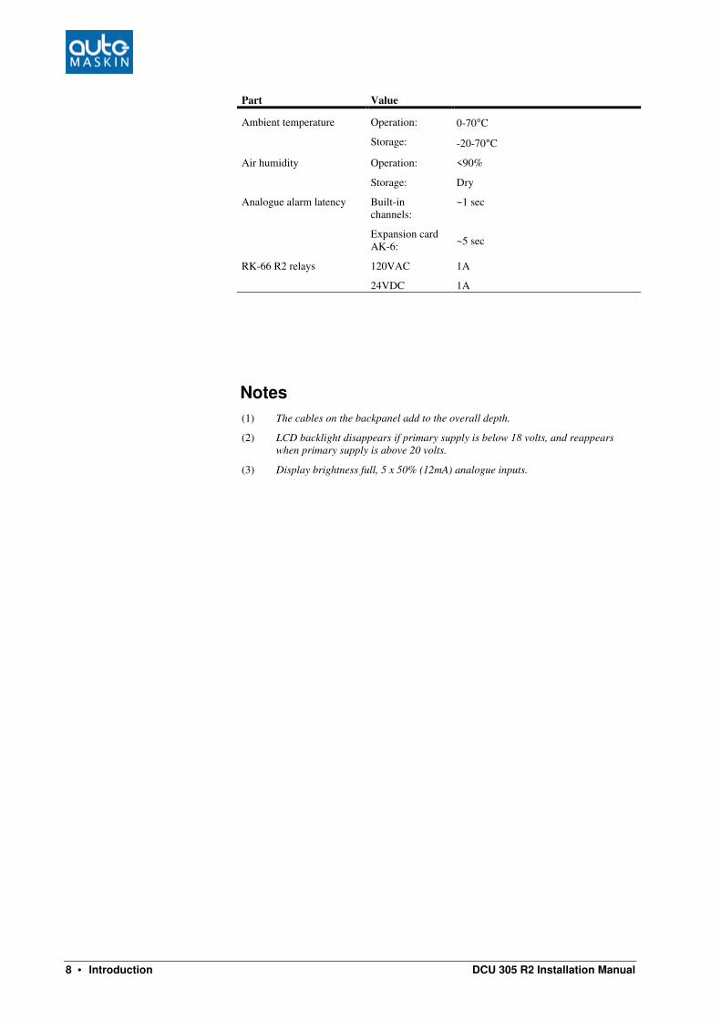
Part Value
Ambient temperature Operation:
Storage:
0-70°C
-20-70°C
Air humidity Operation:
Storage:
<90%
Dry
Analogue alarm latency Built-in channels:
Expansion card AK-6:
~1 sec
~5 sec
RK-66 R2 relays
120VAC
24VDC
1A
1A
Notes
(1) The cables on the backpanel add to the overall depth.
(2) LCD backlight disappears if primary supply is below 18 volts, and reappears
when primary supply is above 20 volts.
(3) Display brightness full, 5 x 50% (12mA) analogue inputs.

DCU 305 R2 Installation Manual Cable connection • 9
Cable connection
General
To protect against EMC noise, we recommend that all cables be screened.
The screen of all cables shall be connected to ground, not to 0V! Some cables are to be grounded in one end only, others in both ends.
Some cables shall be separate – for instance pickup signal. Others can be in a multicable with screen.
See the example schematics and cable specification for details.
Grounding
Please keep ground and 0V separated!
Please observe the
difference between Ground
and 0 volt!
In marine installations, ground and 0 volt should not be connected together. In a ship installation, the hull is the “ground” whilst the battery minus is the 0V.
In the DCU 305 R2 system, +24V and 0V are filtered to ground using special filter components. This is done to avoid noise in the system. If ground and 0V is connected together, these filters do not work properly.
In general, all switches should be referenced to 0V.
Connection order
All connections are made on the RK-66 terminal card. The only exception is communication cables, and analogue/relay expansion cables, which are connected directly on the backpanel.
Start by connecting the ground cable to terminal 60 on the RK-66 R2 terminal board. Terminal 60 is connected to the groundplane (not to 0V) on the RK-66 R2 card.

10 • Cable connection DCU 305 R2 Installation Manual
The RK-66 R2 wire terminal card
Now, connect the rest of the wires and complete the installation by connecting power to the supply inputs.
Terminals 1 and 2 are for the start battery supply, and terminals 3 and 4 are from the auxiliary supply.
Switch setting
By removing the rubber lid on the front of the RK-66, four dip-switches numbered 1-4 will appear.
Switch Purpose Factory
Setting
1 When ON, start is enabled. This is the same as connecting a jumper over terminals 39 and 40.
When OFF, no starts are possible! Now, a jumper between terminals 39 and 40 will enable start.
ON
2 When ON, bypasses the return path diode to start-battery negative (terminal 2), which in some installations may reduce noise interference.
Increases the measured battery voltage by 0.3V.
OFF
3 Noise filter between terminal 1 and 3 to ground.
Set the switch to ON to enable the filter.
OFF
4 Noise filter between terminal 2 and 4 to ground.
Set the switch to ON to enable the filter.
OFF
Power supply
24V supply
Use a twisted pair wire to minimize the effect of noise on the cable.
The start battery power must be connected to terminal 1 and 2. This is the primary supply. The secondary (or auxiliary) supply is connected to terminal 3 and 4.
Note: In a classified system, a redundant supply must be connected to terminals 3 and 4.
Connect the two
cables between the
RK-66 R2 and the
control unit.

DCU 305 R2 Installation Manual Cable connection • 11
The control unit uses the highest voltage available. The primary voltage is constantly monitored and displayed on the LCD.
The control unit alarms if the primary supply is below the configured value, or when the secondary supply is below 12V (fixed setpoint).
The LCD light disappears when the primary voltage drops below 18V, and reappear when the primary voltage rises above 20V.
12V supply
The DCU 305 R2 is a 24V system, but can be used in 12V systems using an external DC/DC converter. The configuration in Rudolf must be switched to a 12V system.
Connect the start battery to the primary input at terminal 1 and 2 as above. This voltage is not high enough to make the control panel work, but it measures the battery voltage.
Connect a 12/24V DC/DC converter to the 12V start battery, and connect the 24V output to the secondary input, terminal 3 and 4.
Start- and Stop Relay Outputs
Connect auxiliary relays for Start (cranking), Stop, Run solenoid and Shutdown solenoid.
Observe polarity if the relay coils are fitted with voltage suppressor diodes.
Coil resistance on auxiliary relays must be in the range 250ohm-2kohm.
Pickup sensors
Connect the pickup 1 between terminal 5 and 6. Please verify that the signal strength is between 2.5-30Vpp.
Note: The pickup cable must be shielded to ground, NOT to 0V.
Two pickups
If two pickups are being used, connect the second pickup to terminal 65 and 66. If the rpm differs >100rpm for 20 seconds, there will be an alarm on the pickup with the lowest rpm.
The signal from pickup 1 has precedence, unless the frequency from pickup 2 is >100rpm higher than pickup 1, where pickup 2 will be used.
Note: Two Pickups must be enabled in Rudolf before it can be used.

12 • Cable connection DCU 305 R2 Installation Manual
Switch Input Channels
The control unit has 12 on/off inputs. All 12 inputs can be fully customised with text, delays and instructions to give a Warning, Alarm or Shutdown.
Channel 1 2 3 4 5 6 7 8 9 10 11 12
Terminal # 7 8 9 10 11 12 13 14 15 16 17 18
Switch Input Channels and their corresponding wire terminal number on the RK-66 R2
wire terminal card.
Inputs are connected to the Wire Terminal Card RK-66 as in the above table.
The six first switch input channels can detect a broken wire situation, and utilizes a backup system for shutdown purposes. See page 17 for more information on the backup system.
Note: In a classified system, all shutdown switches must be connected to switch inputs 1-6.
The following table illustrates the capabilities of the switch input channels.
Channel Broken Wire
Detection possibility
Backup on
Shutdown channels
Warning, Alarm and
Shutdown possibility
1-6 Yes Yes Yes
7-12 No No Yes
Note: Do not connect +24V to the switch inputs! All input switches must be connected via its corresponding wire terminal to 0V, not to ground. Please see the schematic drawing page 31.
Connecting the Switches
Connect the warning, alarm and/or shutdown switches according to the project documentation and drawings. All switches must be connected between a wire terminal (7-18) and 0V.
An open (not connected) input is pulled ‘high’ internally. The external switch must pull the input ‘low’ (0V).
Example: Switch channel 1 might be the Oil Pressure Low Shutdown. The switch is then connected between Terminal 7 and 0V.

DCU 305 R2 Installation Manual Cable connection • 13
Wire break detection
Channel 1-6 has the ability to detect wire break. This is useful in conjunction with the channel being used as a shutdown channel.
A 10k resistor (10 000 ohm) must be connected in parallel with the switch. The resistor must withstand 1/8W (0.125W) or more.
Note: The Wire Break Detection feature must be enabled in Rudolf for each of the channels 1-6 that are being used. Otherwise, there will not be a Broken Wire alarm.
The control panel will now issue a “Broken Wire” alarm if the wire into the control panel is broken. The alarm is delayed 5 seconds (fixed time).
An alarm is displayed as:
* Broken Wire [T9]
Here, there is a broken wire on T9, terminal 9. Terminal 9 is switch channel 3.
Considerations when using wire break detection
Make sure the return-path from the external switch is connected to 0V (terminal 29) close to the connection card RK-66 R2, not at the engine.
The reason being that the control unit measures voltage differences, and there could be a substantial voltage difference between 0V at the RK-66 R2 card, and 0V at the engine.
Too great voltage difference may trigger the “Broken Wire” alarm erroneously.
Analogue Input Channels
The control unit has five industrial-standard 4-20mA inputs. These may or may not be used, and – if used – are displayed on the LCD as horizontal bars.
Note: An optional expansion card, the AK-6, is available to expand the number of analogue inputs from 5 to 11. Please see page 23 for details.
Using Rudolf, all 11 analogue channels can be configured as a 0-20mA or 4-20mA type. Channel 1 only can in addition be configured as 0-10V.
Note: If channel 1 is used as 0-10V, use a separate shielded cable for this signal as the 0-10V signal is highly susceptible to noise.
All analogue channels can be customised with text and delays and whether to issue a Warning, Alarm or Shutdown.
Note: Analogue channel one only, can be configured as a 0-10V channel. The dipswitch J12 inside the unit must be set as follows:

14 • Cable connection DCU 305 R2 Installation Manual
0-20mA / 4-20mA
0-10V
Please note that this is applicable for analogue channel one only! Default setting is 0-20mA / 4-20mA.
Analogue channel setpoints
In the display, the following markers are used to distinguish between different types of setpoints:
None No setpoint
Warning Dashed line
Alarm Single line
Shutdown Double line
The alarm Analogue Sensor Failure appears if an enabled analogue input is not connected, or if the signal strength is too low (<2mA).
Instead of a value to the right of the bargraph, the sign “----“ will be displayed, for instance like this:
Oil Pressure OP1
---- Bar
If 0-10V or 0-20mA is selected, the Analogue Sensor Failure alarm will not appear.
Connecting the Analogue Sensors
Connect the sensors according to the project documentation and drawings. All five analogue input channels are 0/4-20mA or 0-10V (channel 1 only).
For PT100 and PT1000 sensors, an appropriate signal converter must be used.
RK-66 R2 terminal number
Analogue
Channel
+24V supply to
sensor
Analogue input
1 19 20
2 21 22
3 23 24
4 25 26
5 27 28
Analogue Input Channels and the corresponding wire
terminal number on RK-66 R2

DCU 305 R2 Installation Manual Cable connection • 15
Terminal 19, 21, 23, 25 and 27 are all +24V supply outputs. These outputs are fused with a common, internal, automatic fuse (F3). The fuse is located on the RK-66 R2 card.
The fuse will automatically reset when the overload or short circuit is removed. An alarm is given if the fuse blows and the alarm stays activated as long as the short circuit is present.
For fuse sizes and characteristics, please see page 17.
Example: Analogue channel 1 might be the Oil Pressure sensor. The sensor is then connected between terminal 19 (+24V supply) and terminal 20 (4-20mA input).
Miscellaneous connection
Please also refer to the schematics, page 31, for the following connections.
Remote Start
Remote Start works as the local Start Button.
Connect terminal 31 to terminal 30 to engage.
Remote Stop
Remote Stop works as the local Stop Button, except it is immediate
Connect terminal 32 to terminal 30 to engage.
Note: For safety reasons, local and remote Start and Stop works regardless of the Manual and Standby setting.
Remote Reset (Acknowledge)
Connect terminal 37 to terminal 36 to activate Remote Reset.
This works as the local reset button on the frontpanel, and reset all the current alarms.
Blackout Start
When the control unit is set to Standby and receives this signal, it will initiate the Automatic Start procedure. The number of start attempts is configured in Rudolf.
Connect terminal 34 to terminal 33 to activate. See the schematics on page 31.
When the engine has started, the signal can be removed. The engine will not stop if the signal is removed.
16 • Cable connection DCU 305 R2 Installation Manual
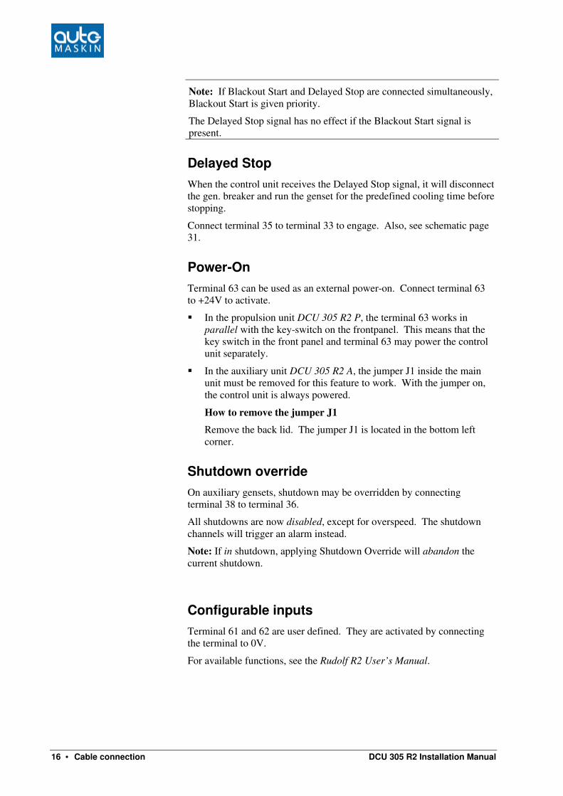
Note: If Blackout Start and Delayed Stop are connected simultaneously, Blackout Start is given priority.
The Delayed Stop signal has no effect if the Blackout Start signal is present.
Delayed Stop
When the control unit receives the Delayed Stop signal, it will disconnect the gen. breaker and run the genset for the predefined cooling time before stopping.
Connect terminal 35 to terminal 33 to engage. Also, see schematic page 31.
Power-On
Terminal 63 can be used as an external power-on. Connect terminal 63 to +24V to activate.
§ In the propulsion unit DCU 305 R2 P, the terminal 63 works in parallel with the key-switch on the frontpanel. This means that the key switch in the front panel and terminal 63 may power the control unit separately.
§ In the auxiliary unit DCU 305 R2 A, the jumper J1 inside the main unit must be removed for this feature to work. With the jumper on, the control unit is always powered.
How to remove the jumper J1
Remove the back lid. The jumper J1 is located in the bottom left corner.
Shutdown override
On auxiliary gensets, shutdown may be overridden by connecting terminal 38 to terminal 36.
All shutdowns are now disabled, except for overspeed. The shutdown channels will trigger an alarm instead.
Note: If in shutdown, applying Shutdown Override will abandon the current shutdown.
Configurable inputs
Terminal 61 and 62 are user defined. They are activated by connecting the terminal to 0V.
For available functions, see the Rudolf R2 User’s Manual.

DCU 305 R2 Installation Manual Cable connection • 17
The automatic fuses on the RK-66 R2 module
The RK-66 R2 wire terminal card has six automatic fuses.
§ Fuses F1, F2 and F5 are used by the DCU 305 R2 to secure internal circuits.
These fuses are of type Raychem Polyswitch™ type RXE090. Maximum load must be less than 1.4A.
§ Fuse F6 secures the +24V power for the analogue channels at terminal 19, 21, 23, 25 and 27. Fuse F3 secures power for the relays connected to terminal 41-44. See the schematics on page 31.
§ Fuse F4 secures the 0V on terminals 29, 30, 33 and 36.
The fuses F3, F4 and F6 are of type Raychem Polyswitch™ type RXE050. Maximum load must be less than 0.8A.
If the values are exceeded, the fuse will eventually blow. When the overload is removed, the fuse repairs itself. Typical recovery time is 15-20sec at 20°C ambient temperature.
Backup system configuration
Overview
In the unlikely event of failure in the DCU 305 R2 main microcontroller, the built-in backup system will detect this, and set the common alarm output relay.
Likewise, if the backup system fails, the main microcontroller will issue the “Backup System Failure” alarm.
Note: The backup system setting is calculated automatically by Rudolf R2.
Set the DIP-switches according to the Rudolf R2 recommendation.
Note: The backup system activates if the main microcontroller fails only. When the control panel is working normally, the backup system is enabled, but not activated.
The working of the backup system can be observed on the back panel as a slowly flashing (~1Hz) green LED. If the LED is flashing quickly, (~4Hz) the backup system has detected a main microcontroller failure and is activated.
The backup system monitors all of the enabled switch inputs channels 1-6, and overspeed. These are the only channels on which the backup system can act.

18 • Cable connection DCU 305 R2 Installation Manual
How it works
If the backup system is activated and a genuine shutdown appears, it activates the Stop and Shutdown outputs on terminal 42 and 44.
These outputs are held active for 2 minutes before being released.
Configuration of dipswitches
All configurations of the backup system is done using switch S1-S4 on the back-panel. There are three settings to be made:
• Set pulses/revolution using hex-switch S1 and S2.
• Set the overspeed setpoint using hex-switch S3.
• Enable shutdown switch channels by setting dipswitch S4.
Pulses/Revolution, S1 and S2
Set the pulses/revolution on pickup #1 (connected to terminals 5 and 6) by switching the two rotary hex-switches S1 and S2 to the correct value.
See the Appendix page 41 for details.
MS is the most significant value whereas LS is the least significant value.
Example: A pickup issues 165 pulses/revolution. 165 decimal = A5 hex.
A is the MS; 5 is the LS.
Set S1 = A Set S2 = 5
Overspeed, S3
Note: The Backup System measures rpm from pickup 1 only.
Set correct overspeed setpoint by turning the hex-switch as follows:
Switch S3 Value [rpm] Switch S3 Value [rpm]
0 Disabled 8 1800
1 480 9 1885
2 670 A 2010
3 1025 B 2030
4 1370 C 2120
5 1670 D 2340
6 1720 E 2430
7 1760 F 2730

DCU 305 R2 Installation Manual Cable connection • 19
Select the next value that is above the Rudolf R2 overspeed setting.
Example: If the main configuration overspeed is set to 1740, then set the S3 switch to 7, ie. 1760 rpm.
Shutdown channels, S4
There is a dipswitch in combination with each of the first six switch channels.
The DIP-settings are for selection of the shutdown channels. All of the channels 1-6 that are configured as shutdown must have its corresponding DIP set to ON.
In the example below, channels 1, 2 and 6 are set as shutdown channels.
Note: The backup settings MUST correspond with the Rudolf R2 configuration.
When the DIP is set to ON, it means these channels will be monitored by the backup system.
In the backup system, there is a four second delay before pulling the stop-solenoid. Once activated, the stop-solenoid remains activated for 2 minutes to allow the engine to completely stop. The stop-solenoid then deactivates.
Shutdowns
Overspeed
Puls/Rev LS
Puls/Rev MS
Example of Backup System setting.
The above example is a system with shutdowns on channel 1, 2 and 6, overspeed set to
1760 rpm and 165 pulses/revolution (see text above)
In the above example, channel 1, 2 and 6 are shutdown channels. Here, channels 3, 4 and 5 may be configured as Warning or Alarm channels, or may not be in use.
A 5 7 ¯ ¯ _ _ _ ¯
S1 S2 S3 S4

20 • Cable connection DCU 305 R2 Installation Manual
Built-in Alarms
The control unit has a number of internal alarms. These are always displayed – in the language selected by Rudolf.
The following is a list of the built-in alarms.
Alarm text Comment
Low battery voltage Low voltage at the start battery.
The alarm is interlocked during starting (cranking) and stopping.
Secondary battery low voltage
Low voltage at the secondary battery source.
Overspeed Engine running faster than the overspeed setpoint.
Engine Stopped Engine stopped for no known reason.
Engine failed to stop 60 seconds after issuing the stop command, the engine has still not stopped.
Start Failure Engine failed to start after the last start attempt.
Pickup failure Unable to read the pickup signal while engine is running.
Output circuit overload Short circuit in one of the +24V outputs.
The outputs are secured with fuse F3 that makes an automatic reset. Remove the overload to correct the problem.
For details, see page 17.
Analogue sensor failure [A7]
Detailed information on which analogue channel that is below 2mA. Here channel 7.
Broken wire [T7 T9 T44] Information on which terminal has a broken wire. Here on terminal 7, 9 and 44.
Adjusting the LCD screen
The control unit uses a graphical Liquid Crystal Display.
The optical performance of the display changes with temperature, light conditions and age.
There is a built-in automatic compensation for temperature changes. Still, from time to time, it may be necessary to adjust the display.
Automatic Backlight Shutoff
To preserve LCD lifetime, the display automatically shuts off after the predefined amount of time, if no action has been observed in that period.
The display turns on again at any key press, or if an event occurs in the system.

DCU 305 R2 Installation Manual Cable connection • 21
Note: The terminals 61 and 62 can be configured as LCD Backlight On. 0V on the terminal will trigger the LCD Backlight On.
Contrast
Contrast is automatically compensated for with temperature.
If however the display seems dim or unclear, it may be necessary to adjust it. This is done by pressing and holding the Lamptest button, and then pressing the Up- or Down arrows,5/6.
The Up arrow gives a lighter display (less contrast); the Down arrow gives a darker display (more contrast).
The new setting is automatically stored in internal memory, and stays resident regardless of future power loss.
Brightness
It is possible to change between half and full light intensity.
This is done by pressing and holding the Lamptest button, and then pressing the Ackn. button. Each press of the Ackn. button now toggles between half and full display intensity.
This setting is NOT stored. After a power loss, the control unit starts over with full light intensity again.
Day / Night mode
In the DCU 305 R2 P propulsion unit only, day or night light conditions can be selected.
Pressing the Buzzer Off button for ~1 second toggles the selection. The middle status field will indicate the selection with the text “Day” or “Night”.
Day mode
This is the standard operation mode. LCD backlight is on and LEDs are on. The timeout for the LCD backlight is as configured in Rudolf.
Night mode
In normal situations, LCD backlight is off and LEDs are off.
If a Warning condition occurs, only the Warning LED will flash. The LCD will remain dark.
In an Alarm or Shutdown situation, the LCD backlight is set to half bright and LEDs are powered.
The LCD and LEDs turns off 5 seconds after acknowledge.

22 • Cable connection DCU 305 R2 Installation Manual
Overspeed test
This section describes how to enter the RPM-test mode. In test mode, the Overspeed Setpoint (typically 1725 rpm) is reduced to Nominal Setpoint (typically 1500 rpm).
Note: The actual setpoints may vary from the above example. Consult the Rudolf configuration.
How to enter the RPM test mode
Follow these steps to enter the RPM-test mode:
§ Enter the Information view by pressing Info (top right button) for 2 seconds.
§ In the Information view, press and hold Lamptest (bottom right button) for 20 seconds – until a beep is heard.
The Overspeed Setpoint is now reduced to the Nominal Setpoint. The bottom left status field displays “RPM TEST ” to indicate and remind of this.
Note: The test automatically times out after 4 minutes. To leave the test earlier, press Lamptest once in the Info view.
It is not possible to enter the RPM TEST mode unless the control unit is in the Ready state.

DCU 305 R2 Installation Manual Optional expansion modules • 23
Optional expansion modules
Relay cards MK-6 and MK-14
In addition to the nine relays found on the RK-66 terminal board, an optional relay card may be connected.
The relay cards are available in two sizes – 6 and 14 relays – named MK-6 and MK-14 respectively. Only one relay card may be connected.
The optional MK-6 and MK-14 relay cards, that add six or 14 relay channels to the DCU
305 R2. The function on each relay is configured using the configuration tool Rudolf.
All relays can be given any function from an extensive signal pool.
The relay card is connected to the control unit with a shielded 15-pin D-SUB connector cable, and is then ready for use.
The relays are rated 220V/5A.
For connections, please see page 38.

24 • Optional expansion modules DCU 305 R2 Installation Manual
Available signals to the relay cards
These are all the available signals in the DCU 305 R2 that can be routed to any of the relays on the relay cards.
Relay K7 and K9 on the terminal card RK-66 R2 are configurable in the same manner.
Signal Comment
Acknowledge button Manual press of the Acknowledge button.
Analogue sensor failure
An analogue input (4-20mA) is defined but the signal is less than 2mA.
Backup system failure
The backup system is not working.
Buzzer active Buzzer is activated.
Buzzer off button Manual press of the Buzzer Off button.
Common analogue input current overload
The sensor fuse is blown. The fuse resets itself when the short circuit is removed.
Common shutdown Sum of all shutdown channels.
Common warning Sum of all warning channels
Cooling state The genset is cooling and running at no load.
Cranking state The Control Unit signals the start motor. The genset is cranking. On between start attempts also.
Delayed stop activated
The Control Unit has received signal saying the genset will eventually stop.
Disconnect gen breaker relay activated
The generator circuit breaker relay is activated.
Downloading parameters
A new configuration is being transmitted to the control unit.
Engine started The Control Unit detects the engine is running but no start signal has been detected.
Engine stopped for unknown reason
The engine stopped for no known reason.
First start attempt failed
The first of several start attempts failed during automatic start.
Local mode LOCAL mode is selected, and no remote commands will work.
Lamptest button Manual press of the Lamptest button.
Manual mode The Control Unit is set to Manual mode.
Manual stop Manual Stop button, local or remote.
Overspeed Engine speed too high. Stays until Acknowledged.
Pickup failure Unable to detect a valid pickup signal. Dependent upon at least one defined Additional RUN Detection.

DCU 305 R2 Installation Manual Optional expansion modules • 25
Signal Comment
Sum of pickup 1 and 2.
Preheat Preheating before and during start attempts. Stays on until engine has started or failed to start.
Ready to start The genset is ready to start.
Ready to take load The engine has reached the in Rudolf predefined rpm-setting.
Running state The genset is running. On as long as the engine is running. Same as green LED in the Start button.
Secondary battery failure
The secondary battery is not connected or its voltage is below 12V. Terminal 3 and 4.
Shutdown override on
The Control Unit is disabling shutdowns, except overspeed.
Shutdown override off
The Control Unit has all configured shutdowns enabled.
Standby mode The Control Unit is set to Standby mode. Automatic starts can take place.
Start battery low voltage
The engines start battery has low voltage. Terminal 1 and 2.
Start command externally
Same as the Blackout signal, e.g. from main switchboard. Terminal 34.
Start disabled The Control Unit is disabling local and remote start attempts, also when set to Standby.
Start failure The engine did not start after final start attempt.
Stop failure A stop signal was given but after 40 seconds, the engine is still running.
Stopped state The engine has stopped. Engine speed is less than 5rpm.
Stopping state The engine is about to stop.
All channels – analogue or switch – configured as a warning, alarm or shutdown can be routed to any relay.
A screenshot from the configuration tool Rudolf R2, where signals
are selected to the relays.

26 • Optional expansion modules DCU 305 R2 Installation Manual
Analogue card AK-6
The analogue card AK-6 connects directly into the DCU 305 R2. Another six analogue channels are then available in the control unit, to make 11 channels.
The card has two 15-pin D-SUB connectors. One connects directly to the control unit. The other connects to the optional relay expansion cards MK-6 or MK-14, if used.
If any of the analogue channels 6-11 are activated in Rudolf, the control unit assumes the AK-6 card is connected.
All input channels on the AK-6 are of type 4-20mA.
Note: The update time for the six expansion channels is longer than for the five standard channels. The standard channel 5 will also have longer update intervals when AK-6 is used. We recommend connection of “slow” media to the AK-6 card, eg. temp. transmitters.
Note: When using the AK-6 card and the MK-14 card together, the last three channels (channel 12, 13 and 14) on the MK-14 are unavailable.
The optional AK-6 analogue card, which adds six 4-20mA channels to the DCU 305 R2.

DCU 305 R2 Installation Manual Optional expansion modules • 27
Connections
The fifth analogue input on the RK-66 R2 card (terminal 27 and 28) becomes the first analogue input on the AK-6 card.
If there is a connection at terminal 27 and 28 on the RK-66 card, move these to terminal 1 and 2 on the AK-6 card.
Consider the following table when using the AK-6 analogue expansion card.
RK-66 terminal # AK-6 terminal #
Channel +24V 4-20mA +24V 4-20mA Screen
1 19 20 1
2 21 22 1
3 23 24 1
4 25 26 1
5 27 28 1 2 1
6 3 4 2
7 5 6 2
8 7 8 2
9 9 10 2
10 11 12 2
11 13 14 2
For further connection information, please see the schematic.
On the AK-6, connect terminal 27, 28 and 29 directly to terminal 27, 28 and 29 on the RK-66.
Terminal 29 on the AK-6 is a 0V that can be connected to sensors that need a +24V and a 0V connection. Otherwise, disregard it.
Terminals 15 and 16 on the AK-6 are not in use.
Displaying the analogue values
As illustrated in the table above, channel 1-5 will be displayed in the first analogue screen, along with the battery voltage (standard).
Screen 2 displays channels 6-11. Screen 2 is not available if none of the channels 6-11 are in use.

28 • Communication DCU 305 R2 Installation Manual
Communication
The information from sensors and switches connected to the DCU 305 R2 can be remotely monitored by utilising the built-in communication channel.
Any common supervision system like Factory Link®, InTouch®, etc. that supports the Comli or Modbus
1RTU protocols can be used.
When connected, most data available on the DCU 305 R2 display is available in the supervision system. In addition, commands such as Start, Stop and Acknowledge alarms can be done.
Protocol and pin-configuration
The DCU 305 R2 has the Comli and Modbus RTU communication protocols built-in. It communicates at 9600 baud on its RS-232 communication port.
In order to communicate, the control units ID-number must be known. This ID-number may be any number in the range 1-239. The printout documentation from Rudolf includes the ID-number.
Please refer to the DCU 305 R2 Communication Interface for a complete reference when communicating to the control panel.
The control panel has a 9-pin D-SUB male connector outlined as follows:
Pin # Description
2 RxD
3 TxD
4 DTR
5 SG
7 RTS
8 CTS
1 Modbus is available from firmware 4.25.

DCU 305 R2 Installation Manual Communication • 29
Multidrop communication
Several DCU 305 R2 units may be connected together in what is known as a multidrop network.
For this to work correctly, each of the connected units must have its unique ID-number in the range 1-239. This is done using the parameter program Rudolf R2.
Further, the multidrop net must be an RS-422 net. This means that RS-232/RS-422 converter units, for instance the Phoenix PSM-ME RS-232/RS-422 unit, must be connected close to the communication port of each DCU 305 R2 unit. We recommend using a screened twisted pair cable with two pairs of at least 0.22 mm2, and capacity lower than 60pF/m.
Please contact your dealer or Auto-Maskin for correct dip setting and cabling of these units in a network.
Retrieve the log to a PC
The built-in event log in the control unit can be retrieved with simple means. In Rudolf R2, select Communication – Retrieve Log…
If Rudolf R2 is not available, a laptop with a terminal program like Hyperterm or similar can be used.
Connect and set up communication parameters
Start the terminal program and adjust the communication parameters as follows:
§ 9600 baud
§ 8 databits
§ 1 stopbit
§ Odd parity
Connect the Rudolf R2 cable, or use a cable with the following outline:
Laptop PC, COM 1
9 pin female D-SUB
DCU 305 R2, P3
9 pin female D-SUB
2 3
3 2
5 5

30 • Communication DCU 305 R2 Installation Manual
Functions
When the cable is connected and the communication parameters of the terminal-program are adjusted, proceed here.
Note: The syntax is <ESC> + <Character>.
The <ESC> key must be followed by an UPPERCASE <character> within 3 seconds.
The following functions are available:
Function Press
Retrieve the complete log with timestamped events. The log is uploaded with the last event first.
<ESC> + L
Retrieve all counters (running hours, etc) <ESC> + C
Retrieve information (text that describes the installation/project) <ESC> + I
The uploaded information can be stored on your laptop for future reference.

DCU 305 R2 Installation Manual Schematic Drawings • 31
Schematic Drawings
Sample schematic page 1

32 • Schematic Drawings DCU 305 R2 Installation Manual
Sample schematic page 2

DCU 305 R2 Installation Manual Schematic Drawings • 33
Optional relay card MK-6

34 • Schematic Drawings DCU 305 R2 Installation Manual
Optional analogue card AK-6

DCU 305 R2 Installation Manual Schematic Drawings • 35
Cable Specification
Terminal Function Cable specifications Comment
1-2 Primary 24VDC supply Twisted pair 1.5 mm2
3-4 Secondary 24VDC supply Twisted pair 1.5 mm2
5-6 Pickup 1 Shielded cable 2 x 0.5
mm2
Separate cable
Shield to be connected to GND at both ends
7-18 Digital inputs Shielded cable 0.5 mm2 Shield to be
connected to GND at both ends
19-20 Analogue input 1
Shielded cable 0.5 mm2
Separate cable if used as
0-10VDC
Shield to be connected to GND at both ends
21-29 Analogue input 2 - 5 Shielded cable 0.5 mm2 Shield to be
connected to GND at both ends
30-32 Remote Start Remote Stop
Shielded cable 0.5 mm2 Shield to be
connected to GND at both ends
33-35 Blackout Start Delayed Stop
Shielded cable 0.5 mm2 Shield to be
connected to GND at both ends
36-38 Remote Acknowledge Shutdown Override
Shielded cable 0.5 mm2 Shield to be
connected to GND at both ends
39-40 Remote Keyswitch Shielded cable 0.5 mm2 Shield to be
connected to GND at both ends
41-44 Relays for Start/Stop Shielded cable 0.5 mm2
45-59 Relay outputs Unshielded cable max 2.5
mm2
60 GND Unshielded 2.5 mm2
GND cable
Connect to noise-free earth. L<1m
61-62 Configurable inputs Shielded cable 0.5 mm2 Shield to be
connected to GND at both ends
63 External power-on Shielded cable 0.5 mm2 Shield to be
connected to GND at both ends
64 Spare input - Not in use 65-66 Pickup 2 Shielded cable 2x0.5 mm
2
Separate cable
Shield to be connected to GND at both ends
DSUB P3
- Rudolf Configuration - Comli/Modbus communication
Shielded cable 0.20 mm2
Separate cable
Shield to be connected to DSUB housing at DCU 305 R2 end only
DSUB P7
AK-6, MK-6, MK-14, C1-C2-C3 cable Expansion port
Shielded cable 0.20 mm2
Separate cable
Shield to be connected to DSUB housing at DCU 305 R2 end only
DSUB P9
J1708, J1587 Shielded cable 0.20 mm2
Separate cable
Shield to be connected to DSUB housing at DCU 305 R2 end only
DSUB P10
CAN, J1939 Shielded cable 0.20 mm2
Separate cable
Shield to be connected to DSUB housing at DCU 305 R2 end only

36 • Schematic Drawings DCU 305 R2 Installation Manual
Wire Terminal Table, RK-66 R2
# DCU 305 R2 A DCU 305 R2 P Comment
1 +24V +24V
2 0V 0V
Primary supply. Connect to start battery.
3 +24V +24V
4 0V 0V
Secondary supply. Connect to auxiliary supply.
5 Pickup 1 Pickup 1
6 Pickup 1 Pickup 1
Used when one pickup only.
2.5 - 30Vpp.
7 Switch input 1 Switch input 1 Referenced to 0V, terminal 29
8 Switch input 2 Switch input 2 Referenced to 0V, terminal 29
9 Switch input 3 Switch input 3 Referenced to 0V, terminal 29
10 Switch input 4 Switch input 4 Referenced to 0V, terminal 29
11 Switch input 5 Switch input 5 Referenced to 0V, terminal 29
12 Switch input 6 Switch input 6 Referenced to 0V, terminal 29
13 Switch input 7 Switch input 7 Referenced to 0V, terminal 29
14 Switch input 8 Switch input 8 Referenced to 0V, terminal 29
15 Switch input 9 Switch input 9 Referenced to 0V, terminal 29
16 Switch input 10 Switch input 10 Referenced to 0V, terminal 29
17 Switch input 11 Switch input 11 Referenced to 0V, terminal 29
18 Switch input 12 Switch input 12 Referenced to 0V, terminal 29
19 +24V +24V Output, protected by fuse F6
20 Analogue input 1,
4-20mA
Analogue Input 1,
4-20mA
21 +24V +24V Output, protected by fuse F6
22 Analogue Input 2,
4-20mA
Analogue Input 2,
4-20mA
23 +24V +24V Output, protected by fuse F6
24 Analogue Input 3,
4-20mA
Analogue Input 3,
4-20mA
25 +24V +24V Output, protected by fuse F6
26 Analogue Input 4,
4-20mA
Analogue Input 4,
4-20mA
27 +24V +24V Output, protected by fuse F6
28 Analogue Input 5,
4-20mA
Analogue Input 5,
4-20mA
29 0V 0V Common 0V
30 0V 0V Common 0V
31 Remote Start Remote Start Connect to terminal 30 to activate
32 Remote Stop Remote Stop Connect to terminal 30 to activate
33 0V 0V Common 0V
34 Blackout Start - Connect to terminal 33 to activate

DCU 305 R2 Installation Manual Schematic Drawings • 37
# DCU 305 R2 A DCU 305 R2 P Comment
35 Delayed Stop - Connect to terminal 33 to activate
36 0V 0V Common 0V
37 Remote Reset Remote Reset Connect to terminal 36 to activate
38 Shutdown Override - Connect to terminal 36 to activate
39 Keyswitch Start Disable
Keyswitch Start Disable
40 Keyswitch Start Disable
Keyswitch Start Disable
Connect a wire between terminal 39 and 40 to enable start.2.
If the wire is removed, start is inhibited.
Set switch SW1 to jumper across terminal 39 and 40.
41 To Start Solenoid To Start Solenoid Relay K1.
+24V supply to auxiliary start relay
42 To Stop Solenoid, +24V
To Stop Solenoid, +24V
Relay K2.
+24V supply to auxiliary stop relay
43 To Run Solenoid, +24V
To Run Solenoid, +24V
Relay K3.
+24V supply to auxiliary run relay
44 To Shutdown Solenoid
To Shutdown Solenoid
Relay K4.
+24V supply to auxiliary shutdown solenoid.
45 Common Alarm, NO
Common Alarm, NO
46 Common Alarm, C Common Alarm, C
47 Common Alarm, NC
Common Alarm, NC
Relay K5.
The Common Alarm relay.
48 Common Shutdown, NO
Common Shutdown, NO
49 Common Shutdown, C
Common Shutdown, C
50 Common Shutdown, NC
Common Shutdown, NC
Relay K6.
The common Shutdown relay.
51 K7, NO Config relay, NO
52 K7, C Config relay, C
53 K7, NC Config relay, NC
Relay K7.
Configurable relay.
54 Ready to Start, NO Ready to Start, NO
55 Ready to Start, C Ready to Start, C
56 Ready to Start, NC Ready to Start, NC
Relay K8.
Activates when ready to start, and not in LOCAL mode or MANUAL mode.
57 K9, NO Config relay, NO
58 K9, C Config relay, C
59 K9, NC Config relay, NC
Relay K9.
Configurable relay.
60 GND – chassis – hull
GND – chassis – hull
Connect to the hull.
61 Config input 1 Config input Configurable input.
62 Config input 2 Config input Configurable input.
2 The wire terminal card has a switch (SW1) connected over terminal 39 and 40. The switch is accessible from underneath the rubber seal on top of the RK-66 R2 terminal card.

38 • Schematic Drawings DCU 305 R2 Installation Manual
# DCU 305 R2 A DCU 305 R2 P Comment
63 Power-on3 Power-on Connect to +24V to power-on in parallel with the keyswitch found on DCU 305 R2 P.
64 Reserved input Reserved input For future expansion
65 Pickup 2 Pickup 2
66 Pickup 2 Pickup 2
For pickup 2.
Use Pickup 1 inputs if there is one pickup only. 2.5-30Vpp.
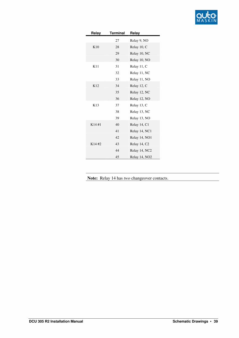
Wire terminal table, relay card MK-6 and MK-14
The functions on these optional relays are user defined using the Rudolf configuration tool.
Relay Terminal Relay
K1 1 Relay 1, C
2 Relay 1, NC
3 Relay 1, NO
K2 4 Relay 2, C
5 Relay 2, NC
6 Relay 2, NO
K3 7 Relay 3, C
8 Relay 3, NC
9 Relay 3, NO
K4 10 Relay 4, C
11 Relay 4, NC
12 Relay 4, NO
K5 13 Relay 5, C
14 Relay 5, NC
15 Relay 5, NO
K6 16 Relay 6, C
17 Relay 6, NC
18 Relay 6, NO
K7 19 Relay 7, C
20 Relay 7, NC
21 Relay 7, NO
K8 22 Relay 8, C
23 Relay 8, NC
24 Relay 8, NO
K9 25 Relay 9, C
26 Relay 9, NC
3 In the DCU 305 R2 A, this feature has no effect unless internal jumper J1 is removed.
MK-6 limit
DCU 305 R2 Installation Manual Schematic Drawings • 39
Relay Terminal Relay
27 Relay 9, NO
K10 28 Relay 10, C
29 Relay 10, NC
30 Relay 10, NO
K11 31 Relay 11, C
32 Relay 11, NC
33 Relay 11, NO
K12 34 Relay 12, C
35 Relay 12, NC
36 Relay 12, NO
K13 37 Relay 13, C
38 Relay 13, NC
39 Relay 13, NO
K14 #1 40 Relay 14, C1
41 Relay 14, NC1
42 Relay 14, NO1
K14 #2 43 Relay 14, C2
44 Relay 14, NC2
45 Relay 14, NO2
Note: Relay 14 has two changeover contacts.

40 • Schematic Drawings DCU 305 R2 Installation Manual
Wire terminal table, analogue card AK-6
Please note that when using the optional AK-6 card, analogue channel 5 is moved from the RK-66 to the AK-6 card.
Terminal AI channel Signal type
1 5 +24V supply
2 à 4-20mA input
3 6 +24V supply
4 à 4-20mA input
5 7 +24V supply
6 à 4-20mA input
7 8 +24V supply
8 à 4-20mA input
9 9 +24V supply
10 à 4-20mA input
11 10 +24V supply
12 à 4-20mA input
13 11 +24V supply
14 à 4-20mA input
15 - NC
16 - NC
27 *) Connect to RK-66 terminal 27
28 *) Connect to RK-66 terminal 28
29 *) Connect to RK-66 terminal 29
*) Connect these three wires between RK-66 R2 and AK-6.

DCU 305 R2 Installation Manual Appendix • 41
Appendix
Ordering information
Article Description Comment
06400 DCU 305 R2 A, Complete with wire terminal
card RK-66R2 and cables
Complete auxiliary/emergency unit
06401 DCU 305 R2 P, Complete with wire terminal
card RK-66 R2 and cables
Complete Propulsion unit
06405 DCU 305 R2 A CU
Control unit only
Main auxiliary/emergency unit only
06406 DCU 305 R2 P CU
Control Unit only
Main propulsion unit only
75410 RK-66 R2
Wire Terminal card
The standard wire terminal card
75262 MK-6
Relay Card with 6 relays, w/ 200cm cable
Relay functions are configured using Rudolf
75263 MK-14
Relay Card with 14 relays, w/ 200cm cable
Relay functions are configured using Rudolf
75268 AK-6
Analogue Card with six 4-20mA analogue input
channels and 200cm cable
Channels are configured using Rudolf
06500 RSP 305
Remote Slave Panel with the look and feel of the
DCU 305.
Configures itself automatically.
For up to four DCU 305 units.
08334 PT100/1000/NICRNI – 4-20mA converter
Configurable
Converts signal into 4-20mA signal
09059 Exhaust Temp monitoring, 8 cylinders Interfaced with the DCU 305 R2. Communicates with the slave panel.
09060 Exhaust Temp monitoring, 12 cylinders Interfaced with the DCU 305 R2. Communicates with the slave panel.

42 • Appendix DCU 305 R2 Installation Manual
Article Description Comment
09061 Exhaust Temp monitoring, 16 cylinders Interfaced with the DCU 305 R2. Communicates with the slave panel.
75270 Rudolf R2 Parameter Program
Configuration tool
Delivered on a CD
(Manual included; article 09326)
75225
Rudolf R2 configuration cable
200cm
Cable has female D-SUB 9 connectors
09326 Rudolf R2 User’s Manual, English The configuration tool manual
06322 DCU 305 R2 User’s Manual, English User’s Manual
06323 DCU 305 R2 User’s Manual, Norwegian User’s Manual, native language
06324 DCU 305 R2 Communication Manual For communication purposes
06325 DCU 305 R2 Installation Manual This document
Dec-to-Hex table
Use this table to configure the built-in backup system. Alternatively, use the values set by Rudolf.
Dec Hex
1 01
2 02
3 03
4 04
5 05
6 06
7 07
8 08
9 09
10 0A
11 0B
12 0C
13 0D
14 0E
15 0F
16 10
17 11
18 12
19 13
20 14
21 15
22 16
23 17
24 18
25 19
26 1A
27 1B
Dec Hex
28 1C
29 1D
30 1E
31 1F
32 20
33 21
34 22
35 23
36 24
37 25
38 26
39 27
40 28
41 29
42 2A
43 2B
44 2C
45 2D
46 2E
47 2F
48 30
49 31
50 32
51 33
52 34
53 35
54 36
Dec Hex
55 37
56 38
57 39
58 3A
59 3B
60 3C
61 3D
62 3E
63 3F
64 40
65 41
66 42
67 43
68 44
69 45
70 46
71 47
72 48
73 49
74 4A
75 4B
76 4C
77 4D
78 4E
79 4F
80 50
81 51

2 • Appendix DCU 305 R2 Installation Manual
Dec Hex
82 52
83 53
84 54
85 55
86 56
87 57
88 58
89 59
90 5A
91 5B
92 5C
93 5D
94 5E
95 5F
96 60
97 61
98 62
99 63
100 64
101 65
102 66
103 67
104 68
105 69
106 6A
107 6B
108 6C
109 6D
110 6E
111 6F
112 70
113 71
114 72
115 73
116 74
117 75
118 76
119 77
120 78
121 79
122 7A
123 7B
124 7C
125 7D
126 7E
127 7F
128 80
129 81
130 82
131 83
Dec Hex
132 84
133 85
134 86
135 87
136 88
137 89
138 8A
139 8B
140 8C
141 8D
142 8E
143 8F
144 90
145 91
146 92
147 93
148 94
149 95
150 96
151 97
152 98
153 99
154 9A
155 9B
156 9C
157 9D
158 9E
159 9F
160 A0
161 A1
162 A2
163 A3
164 A4
165 A5
166 A6
167 A7
168 A8
169 A9
170 AA
171 AB
172 AC
173 AD
174 AE
175 AF
176 B0
177 B1
178 B2
179 B3
180 B4
181 B5
Dec Hex
182 B6
183 B7
184 B8
185 B9
186 BA
187 BB
188 BC
189 BD
190 BE
191 BF
192 C0
193 C1
194 C2
195 C3
196 C4
197 C5
198 C6
199 C7
200 C8
201 C9
202 CA
203 CB
204 CC
205 CD
206 CE
207 CF
208 D0
209 D1
210 D2
211 D3
212 D4
213 D5
214 D6
215 D7
216 D8
217 D9
218 DA
219 DB
220 DC
221 DD
222 DE
223 DF
224 E0
225 E1
226 E2
227 E3
228 E4
229 E5
230 E6
231 E7

DCU 305 R2 Installation Manual Appendix • 3
Dec Hex
232 E8
233 E9
234 EA
235 EB
236 EC
237 ED
238 EE
239 EF
Dec Hex
240 F0
241 F1
242 F2
243 F3
244 F4
245 F5
246 F6
247 F7
Dec Hex
248 F8
249 F9
250 FA
251 FB
252 FC
253 FD
254 FE
255 FF
<END>