dc enerium 906211132 ed7 bd planches - chauvin arnoux · display with graphics (fresnel, gauges,...
TRANSCRIPT

Multi-energy power monitors
Multi-energy metering
(electricity, water, gas, etc.)
LV/MV/HV network monitoring
Energy quality
ENERIUM®
yyyyyyyyyyyyyy

Preventive maintenance�� �Installation operating time
�� �Operating time of monitored equipment
Quick programming�� �Current transformer ratios and communication parameters can
be set on the front panel or remotely
�� �Possibility of protection by password
Harmonic analysis�� �Measurement of THD per phase
on U, I and In
�� �Spectral analysis per phase up to the 50th order on U, I and In
Recording
�� � Indices, consumption curves (1) (electricity, water, gas, etc.) and temperature curves (1)
�� �Critical parameters with triggering according to 3 different modes (date, alarm, on-off input) and possibility of pre/post trigger (2)
(1) Load curves. (2) Trend curves.
2 3
FunctionsSimple, intuitive and customizable interface for quick access to the information that you need.
Customizable screens�� �3 screens with 4 display lines each to organize the information
as you wish
Indication of connection errorsbefore operation begins
Validation and navigation keys via drop-down menus
Real-time display of instantaneous, average, min and max values.
Time/date-stamped recording of min and max values
Alarms �� �16 programmable alarms on
instantaneous, average, min and max values, as well as analogue and on-off inputs (e.g. circuit-breaker status)
�� �Recording of the last 64 events (values, dates, times, durations)
�� �Flashing display if there is an alarm
Graphics for easier data analysis
� Checking of connections, unbalance measurement and display of phase shift
�� Monitoring of load factor (display of V, U, I and P)
Local access via USB cable/ optical head for:- programming- reading the data- upgrading the firmware
Qualimetry
� Statistical analysis graphs as per EN50160
� Log of the last 1024 events (dips, outages, overvoltages, overcurrents) Waveform capture (V-U-I-In)
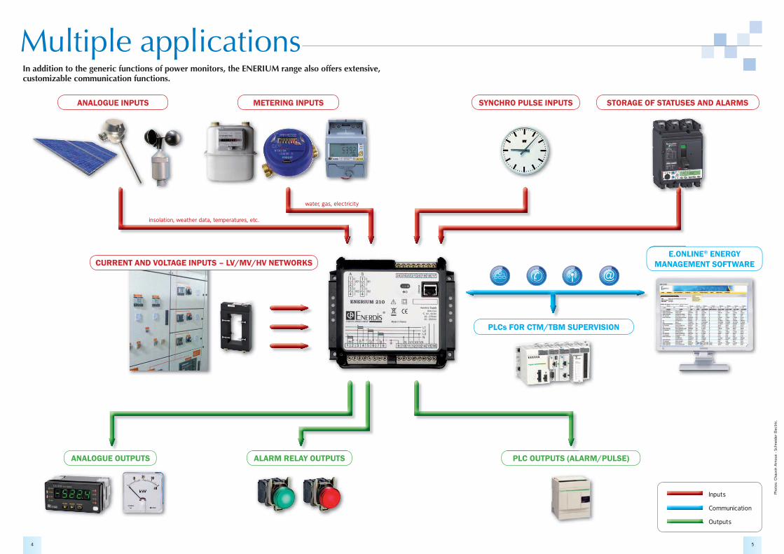
Inputs
Communication
Outputs
Phot
os:
Cha
uvin
Arn
oux
- Sch
neid
er E
lect
ric.
PLCs FOR CTM/TBM SUPERVISION
E.ONLINE® ENERGY MANAGEMENT SOFTWARE
PLC OUTPUTS (ALARM/PULSE)
SYNCHRO PULSE INPUTS STORAGE OF STATUSES AND ALARMS
4 5
Multiple applicationsIn addition to the generic functions of power monitors, the ENERIUM range also offers extensive, customizable communication functions.
insolation, weather data, temperatures, etc.
water, gas, electricity
ANALOGUE INPUTS
CURRENT AND VOLTAGE INPUTS – LV/MV/HV NETWORKS
ANALOGUE OUTPUTS ALARM RELAY OUTPUTS
METERING INPUTS
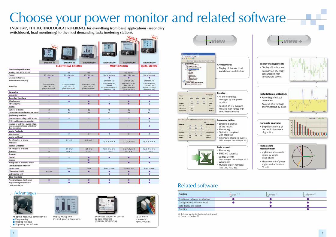
ENERIUM 30 ENERIUM 50 ENERIUM 150 ENERIUM 100 ENERIUM 200 ENERIUM 300ELECTRICAL ENERGY MULTI-ENERGY QUALIMETRY
���������� ����������Accuracy class (IEC61557-12) 1 0.5 0.5 0.5 0.5 ou 0.2 0.2Format 96 x 96 mm 96 x 96 mm 96 x 96 mm 144 x 144 mm 144 x 144 mm 144 x 144 mmGraphic LCD screen � � � � � �
Version without display – – – Enerium 110 Enerium 210 Enerium 310
MountingFlush-mounted,
DIN rail* or plate-mounted*
Flush-mounted, DIN rail* or
plate-mounted*
Flush-mounted, DIN rail* or
plate-mounted*
Flush-mounted, DIN rail*
or plate-mounted* (Enerium 110)
Flush-mounted, DIN rail* or
plate-mounted* (Enerium 210)
Flush-mounted, DIN rail* or
plate-mounted* (Enerium 310)
HarmonicsMax. order – 25 50 25 50 50
Recording functions8 load curves – � � – � �
4 trend curves – – � � � 1
AlarmsNumber of alarms 2 16 16 16 16 16Time/date-stamped events recorded – 64 64 64 64 64
Qualimetry functionsQualimetry according to EN50160 – – – – – �
V, U, I and In waveform capture – – – – – 16Storage of last 1024 events (dips, outages, overvoltages) with time/date-stamping
– – – – – �
Inputs / outputsMax. number 1 2 2 8 8 8
Inputs (optional)On-off (pulses or alarm) – 0,1 or 2 0,1 ou 2
0, 2, 4, 6 or 8 0, 2, 4, 6 or 8 0, 2, 4, 6 or 8Analogue – – –
Outputs (optional)On-off (pulses or alarm) 1 0,1 or 2 0,1 or 2 0, 2, 4, 6, or 8 0, 2, 4, 6, or 8 0, 2, 4, 6, or 8Analogue 0 0 or 2 0 or 2 0.2 or 4 0.2 or 4 0.2 or 4
GraphicsFresnel – – � � � �
Gauges � – � – – –Histograms of harmonic orders – – � – � �
Communication interfaceOptical / USB – Front Front Front or rear Front or rear Front or rear
Ethernet or RS485 RS485 � � � � �
Metrological LED – – – � � �
Other functionsProgramming on front panel � � � � � �
Programming via software – � � � � �
* With mounting kit
Choose your power monitor and related software
Related software
(1) delivered as standard with each instrument(2) Except on Enerium 30
Functions
Creation of network architecture �� �� �� �
Configuration (remote or local) �� �� �
Data display and export � �� �
Graphics � � �
(1) (2) (2) (2)
Architecture:
����������� ������� ����� installation's architecture
A
Summary tables :
������������������� of the results�������������� �� ����������� � with EN50160�������� ��� ��������� � (dips, outages, overvoltages, etc.)
S
Display :
������ ������ � ���� managed by the power monitor
���������������!������! min and max values with time/date-stamping
D
Data export :�������������"#$%�&%�� �� �����+�� ������� �� (dips, outages, overvoltages, etc.)��7���������;�� ������<��� ����� ��=� .csv, .xls, .txt, etc.
Installation monitoring :
������������������ ���� parameters
����������������������� after triggering by alarm
Energy management :
���������������������
��>������������������ consumption with temperature curves
Harmonic analysis :
���������������������� the results by means of graphics
Phase shift measurement :
��?������� �������� easier by simple visual check
��;�������� ��������� angles and unbalance (V, U, I)
6 7
ENERIUM®, THE TECHNOLOGICAL REFERENCE for everything from basic applications (secondary switchboard, load monitoring) to the most demanding tasks (metering station).
Display with graphics (Fresnel, gauges, harmonics)
i l i h hi �Screenless version for DIN-rail or plate mounting (ENERIUM 110/210/310)
Up to 8 on-off or analogue inputs/outputs
U t 8 ffAn optical head/USB connection for :�� �Programming�� �Reading the data�� �Upgrading the software
S l i f DI
ENERIUM 50
Advantages
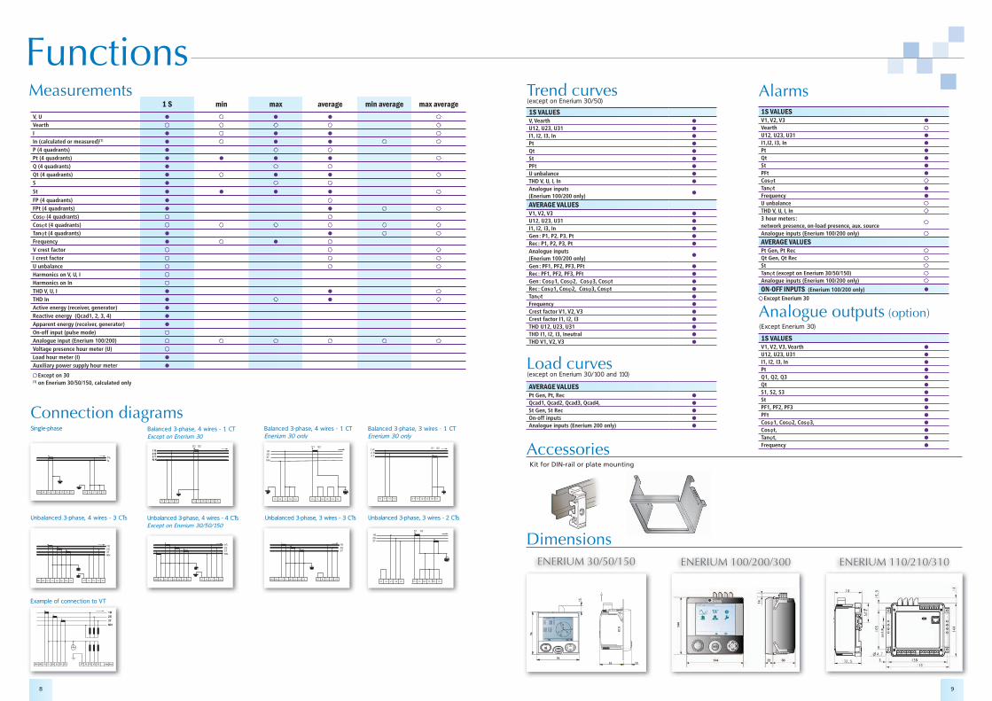
Trend curves Alarms
Analogue outputs (option)
(except on Enerium 30/100 and 110)
(except on Enerium 30/50)
Load curves
Dimensions
Accessories
ENERIUM 30/50/150 ENERIUM 100/200/300 ENERIUM 110/210/310
8 9
FunctionsMeasurements
Connection diagrams
Unbalanced 3-phase, 3 wires - 2 CTs
PhN
Single-phase Balanced 3-phase, 4 wires - 1 CTEnerium 30 only
Balanced 3-phase, 4 wires - 1 CTExcept on Enerium 30
Unbalanced 3-phase, 3 wires - 3 CTs
IN+ IN- I1+ I1- I2+ I2- I3+ I3- VT N V1 V2 V3
1R
2S
3T
NN
Aux Aux
Example of connection to VT
Unbalanced 3-phase, 4 wires - 3 CTs
Balanced 3-phase, 3 wires - 1 CTEnerium 30 only
Unbalanced 3-phase, 4 wires - 4 CTsExcept on Enerium 30/50/150
1 S min max average min average max averageV, U � � �
VearthI � � �
In (calculated or measured)(1) � � �
P (4 quadrants) �
Pt (4 quadrants) � � � �
Q (4 quadrants) �
Qt (4 quadrants) � � �
S �
St � � � �
FP (4 quadrants) �
FPt (4 quadrants) � �
Cos��(4 quadrants)Cos�t�(4 quadrants)Tan�t�(4 quadrants) � �
Frequency � �
V crest factorI crest factorU unbalanceHarmonics on V, U, IHarmonics on InTHD V, U, I � �
THD In � �
Active energy (receiver, generator) �
Reactive energy (Qcad1, 2, 3, 4) �
Apparent energy (receiver, generator) �
On-off input (pulse mode)Analogue input (Enerium 100/200)Voltage presence hour meter (U)Load hour meter (I) �
Auxiliary power supply hour meter �
Except on 30(1) on Enerium 30/50/150, calculated only
Except Enerium 30
1S VALUESV, Vearth �
U12, U23, U31 �
I1, I2, I3, In �
Pt �
Qt �
St �
PFt �
U unbalance �
THD V, U, I, In �
Analogue inputs�
(Enerium 100/200 only)
AVERAGE VALUESV1, V2, V3 �
U12, U23, U31 �
I1, I2, I3, In �
Gen : P1, P2, P3, Pt �
Rec : P1, P2, P3, Pt �
Analogue inputs�
(Enerium 100/200 only)Gen : PF1, PF2, PF3, PFt �
Rec : PF1, PF2, PF3, PFt �
Gen : Cos�1, Cos�2, Cos�3, Cos�t �
Rec : Cos�1, Cos�2, Cos�3, Cos�t �
Tan�t �
Frequency �
Crest factor V1, V2, V3 �
Crest factor I1, I2, I3 �
THD U12, U23, U31 �
THD I1, I2, I3, Ineutral �
THD V1, V2, V3 �
1S VALUESV1, V2, V3 �
VearthU12, U23, U31 �
I1,I2, I3, In �
Pt �
Qt �
St �
PFt �
Cos�tTan�t �
Frequency �
U unbalanceTHD V, U, I, In3 hour meters : network presence, on-load presence, aux. sourceAnalogue inputs (Enerium 100/200 only)
AVERAGE VALUESPt Gen, Pt RecQt Gen, Qt Rec StTan�t (except on Enerium 30/50/150)Analogue inputs (Enerium 100/200 only)
ON-OFF INPUTS (Enerium 100/200 only) �
1S VALUESV1, V2, V3, Vearth �
U12, U23, U31 �
I1, I2, I3, In �
Pt �
Q1, Q2, Q3 �
Qt �
S1, S2, S3 �
St �
PF1, PF2, PF3 �
PFt �
Cos�1, Cos�2, Cos�3, �
Cos�t, �
Tan�t, �
Frequency �
AVERAGE VALUESPt Gen, Pt, Rec �
Qcad1, Qcad2, Qcad3, Qcad4, �
St Gen, St Rec �
On-off inputs �
Analogue inputs (Enerium 200 only) �
(Except Enerium 30)
Kit for DIN-rail or plate mounting
10 11
�����������ENERIUM 30
Class 1ENERIUM 50/150
Class 0.5 sENERIUM 100/200
Class 0.5 sENERIUM 200
Class 0.2 sENERIUM 300
Class 0.2 s
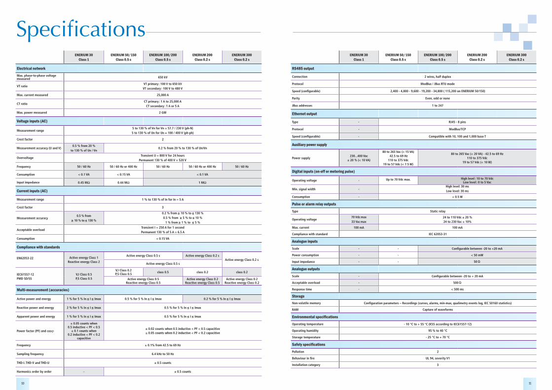
Electrical network
Max. phase-to-phase voltage measured 650 kV
VT ratioVT primary : 100 V to 650 kV VT secondary : 100 V to 480 V
Max. current measured 25,000 A
CT ratioCT primary : 1 A to 25,000 A
CT secondary : 1 A or 5 A
Max. power measured 2 GW
Voltage inputs (AC)
Measurement range5 to 130 % of Vn for Vn = 57.7 / 230 V (ph-N)5 to 130 % of Un for Un = 100 / 400 V (ph-ph)
Crest factor 2
Measurement accuracy (U and V)0.5 % from 20 %
to 130 % of Un / Vn0.2 % from 20 % to 130 % of Un/Vn
OvervoltageTransient U = 800 V for 24 hours
Permanent 130 % of 400 V = 520 V
Frequency 50 / 60 Hz 50 / 60 Hz or 400 Hz 50 / 60 Hz 50 / 60 Hz or 400 Hz 50 / 60 Hz
Consumption < 0.1 VA < 0.15 VA < 0.1 VA
Input impedance 0.45 MJ 0.44 MJ 1 MJ
Current inputs (AC)
Measurement range 1 % to 130 % of In for In = 5 A
Crest factor 3
Measurement accuracy 0.5 % from
≥ 10 % to ≤ 130 %
0.2 % from ≥ 10 % to ≤ 130 % 0.5 % from ≥ 5 % to ≤ 10 %
1 % from ≥ 1 % to ≤ 5 %
Acceptable overloadTransient I = 250 A for 1 secondPermanent 130 % of 5 A = 6.5 A
Consumption < 0.15 VA
Compliance with standards
EN62053-22 Active energy Class 1Reactive energy Class 2
Active energy Class 0.5 s Active energy Class 0.2 sActive energy Class 0.2 s
Active energy Class 0.5 s
IEC61557-12 PMD SD/SS
V,I Class 0.5P,S Class 0.5
V,I Class 0.2 P,S Class 0.5 class 0.5 class 0.2 class 0.2
Active energy Class 0.5 Reactive energy Class 0.5
Active energy Class 0.2Reactive energy Class 0.5
Active energy Class 0.2Reactive energy Class 0.2
Multi-measurement (accuracies)
Active power and energy 1 % for 5 % In ≤ I ≤ Imax 0.5 % for 5 % In ≤ I ≤ Imax 0.2 % for 5 % In ≤ I ≤ Imax
Reactive power and energy 2 % for 5 % In ≤ I ≤ Imax 0.5 % for 5 % In ≤ I ≤ Imax
Apparent power and energy 1 % for 5 % In ≤ I ≤ Imax 0.5 % for 5 % In ≤ I ≤ Imax
Power factor (PF) and cos�
± 0.05 counts when 0.5 inductive < PF < 0.5
± 0.1 counts when 0.2 inductive < PF < 0.2
capacitive
± 0.02 counts when 0.5 inductive < PF < 0.5 capacitive ± 0.05 counts when 0.2 inductive < PF < 0.2 capacitive
Frequency ± 0.1% from 42.5 to 69 Hz
Sampling frequency 6.4 kHz to 50 Hz
THD-I. THD-V and THD-U ± 0.5 counts
Harmonics order by order – ± 0.5 counts
ENERIUM 30Class 1
ENERIUM 50/150Class 0.5 s
ENERIUM 100/200Class 0.5 s
ENERIUM 200Class 0.2 s
ENERIUM 300Class 0.2 s
RS485 output
Connection 2 wires, half duplex
Protocol ModBus / JBus RTU mode
Speed (configurable) 2,400 - 4,800 - 9,600 - 19,200 - 34,800 ( 115,200 on ENERIUM 50/150)
Parity Even, odd or none
JBus addresses 1 to 247
Ethernet output
Type - RJ45 - 8 pins
Protocol - ModBus/TCP
Speed (configurable) - Compatible with 10, 100 and 1,000 base T
Auxiliary power supply
Power supply 230...400 Vac
± 20 % (< 10 VA)
80 to 265 Vac (< 15 VA) 42.5 to 69 Hz110 to 375 Vdc
19 to 57 Vdc (< 7.5 W)
80 to 265 Vac (< 20 VA) - 42.5 to 69 Hz110 to 375 Vdc
19 to 57 Vdc (< 10 W)
Digital inputs (on-off or metering pulse)
Operating voltage - Up to 70 Vdc max. High level : 10 to 70 Vdc Low level : 0 to 5 Vac
Min. signal width -High level: 30 msLow level: 30 ms
Consumption - < 0.5 W
Pulse or alarm relay outputs
Type Static relay
Operating voltage70 Vdc max33 Vac max
24 to 110 Vdc ± 20 %24 to 230 Vac ± 10%
Max. current 100 mA 100 mA
Compliance with standard IEC 62053-31
Analogue inputs
Scale - - Configurable between -20 to +20 mA
Power consumption - - < 50 mW
Input impedance - - 50 Ω
Analogue outputs
Scale - Configurable between -20 to + 20 mA
Acceptable overload - 500 Ω
Response time - < 500 ms
StorageNon-volatile memory Configuration parameters – Recordings (curves, alarms, min-max, qualimetry events log, IEC 50160 statistics)
RAM Capture of waveforms
������������� ����������
Operating temperature - 10 °C to + 55 °C (K55 according to IEC61557-12)
Operating humidity 95 % to 40 °C
Storage temperature - 25 °C to + 70 °C
������� ����������
Pollution 2
Behaviour in fire UL 94, severity V1
Installation category 3
FRANCEEnerdis16, rue Georges Besse - Silic 4492182 ANTONY CedexTél : +33 1 75 60 10 30Fax : +33 1 46 66 62 [email protected]
UNITED KINGDOMChauvin Arnoux LtdUnit 1 Nelson Ct, Flagship Sq, Shaw Cross Business PkDewsbury, West Yorkshire - WF12 7THTel: +44 1924 460 494Fax: +44 1924 455 [email protected]
MIDDLE EAST Chauvin Arnoux Middle East P.O. BOX 60-1541241 2020 JAL EL DIB - LEBANONTel: +961 1 890 425Fax: +961 1 890 [email protected]
90
6 2
11 1
32 –
Ed.
7 –
12
/201
1 -
Non
-con
trac
tual
do
cum
ent
– Pl
ease
con
firm
spe
cific
atio
ns w
hen
orde
ring.
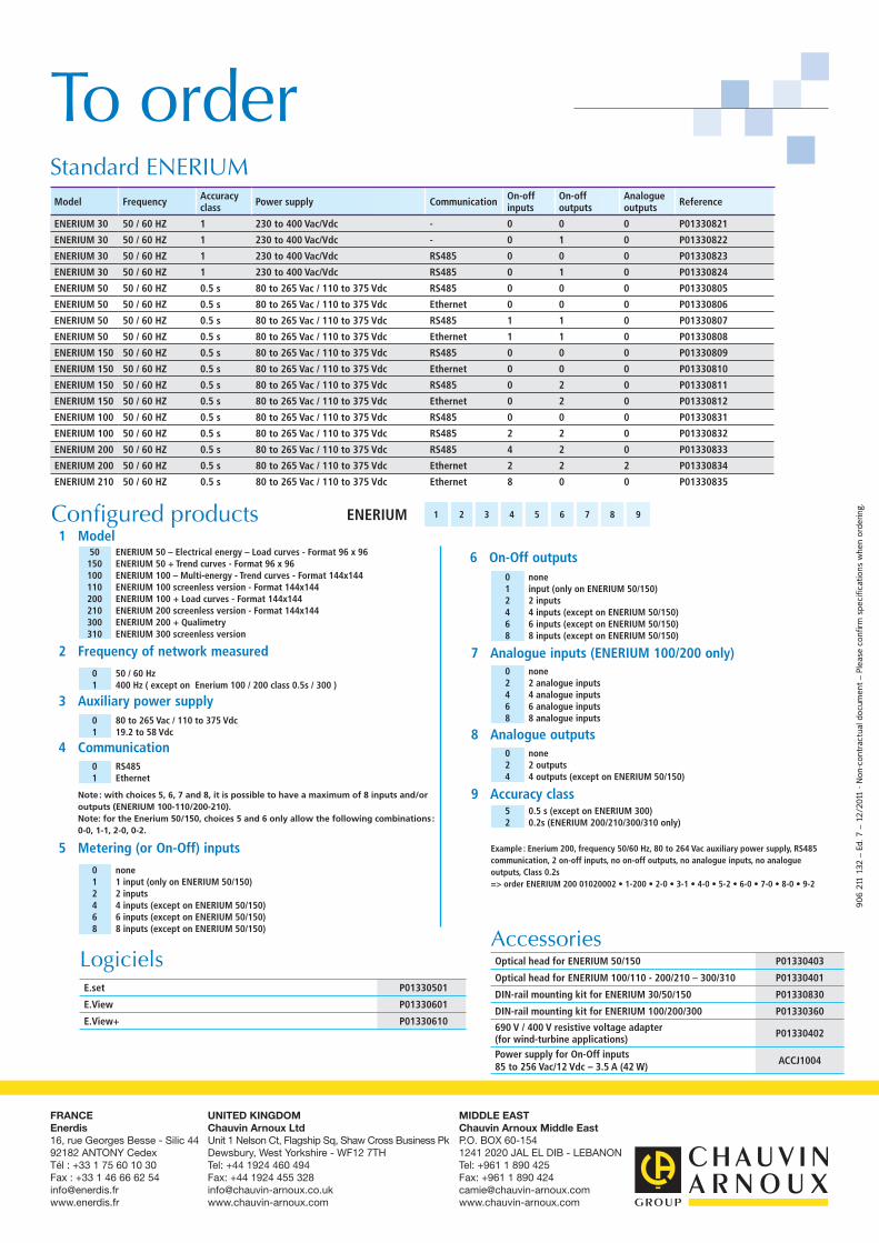
To orderStandard ENERIUM
��������������
Model Frequency Accuracy class Power supply Communication On-off
inputsOn-offoutputs
Analogue outputs Reference
ENERIUM 30 50 / 60 HZ 1 230 to 400 Vac/Vdc - 0 0 0 P01330821
ENERIUM 30 50 / 60 HZ 1 230 to 400 Vac/Vdc - 0 1 0 P01330822
ENERIUM 30 50 / 60 HZ 1 230 to 400 Vac/Vdc RS485 0 0 0 P01330823
ENERIUM 30 50 / 60 HZ 1 230 to 400 Vac/Vdc RS485 0 1 0 P01330824
ENERIUM 50 50 / 60 HZ 0.5 s 80 to 265 Vac / 110 to 375 Vdc RS485 0 0 0 P01330805
ENERIUM 50 50 / 60 HZ 0.5 s 80 to 265 Vac / 110 to 375 Vdc Ethernet 0 0 0 P01330806
ENERIUM 50 50 / 60 HZ 0.5 s 80 to 265 Vac / 110 to 375 Vdc RS485 1 1 0 P01330807
ENERIUM 50 50 / 60 HZ 0.5 s 80 to 265 Vac / 110 to 375 Vdc Ethernet 1 1 0 P01330808
ENERIUM 150 50 / 60 HZ 0.5 s 80 to 265 Vac / 110 to 375 Vdc RS485 0 0 0 P01330809
ENERIUM 150 50 / 60 HZ 0.5 s 80 to 265 Vac / 110 to 375 Vdc Ethernet 0 0 0 P01330810
ENERIUM 150 50 / 60 HZ 0.5 s 80 to 265 Vac / 110 to 375 Vdc RS485 0 2 0 P01330811
ENERIUM 150 50 / 60 HZ 0.5 s 80 to 265 Vac / 110 to 375 Vdc Ethernet 0 2 0 P01330812
ENERIUM 100 50 / 60 HZ 0.5 s 80 to 265 Vac / 110 to 375 Vdc RS485 0 0 0 P01330831
ENERIUM 100 50 / 60 HZ 0.5 s 80 to 265 Vac / 110 to 375 Vdc RS485 2 2 0 P01330832
ENERIUM 200 50 / 60 HZ 0.5 s 80 to 265 Vac / 110 to 375 Vdc RS485 4 2 0 P01330833
ENERIUM 200 50 / 60 HZ 0.5 s 80 to 265 Vac / 110 to 375 Vdc Ethernet 2 2 2 P01330834
ENERIUM 210 50 / 60 HZ 0.5 s 80 to 265 Vac / 110 to 375 Vdc Ethernet 8 0 0 P01330835
ENERIUM 1 2 3 4 5 6 7 8 9
1 Model
2 Frequency of network measured
3 Auxiliary power supply
4 Communication8 Analogue outputs
9 Accuracy class
5 Metering (or On-Off) inputs
6 On-Off outputs
7 Analogue inputs (ENERIUM 100/200 only)
50 ENERIUM 50 – Electrical energy – Load curves - Format 96 x 96 150 ENERIUM 50 + Trend curves - Format 96 x 96 100 ENERIUM 100 – Multi-energy - Trend curves - Format 144x144 110 ENERIUM 100 screenless version - Format 144x144200 ENERIUM 100 + Load curves - Format 144x144210 ENERIUM 200 screenless version - Format 144x144300 ENERIUM 200 + Qualimetry310 ENERIUM 300 screenless version
0 50 / 60 Hz1 400 Hz ( except on Enerium 100 / 200 class 0.5s / 300 )
0 80 to 265 Vac / 110 to 375 Vdc1 19.2 to 58 Vdc
0 RS4851 Ethernet
0 none2 2 outputs4 4 outputs (except on ENERIUM 50/150)
5 0.5 s (except on ENERIUM 300)2 0.2s (ENERIUM 200/210/300/310 only)
0 none1 1 input (only on ENERIUM 50/150)2 2 inputs4 4 inputs (except on ENERIUM 50/150)6 6 inputs (except on ENERIUM 50/150)8 8 inputs (except on ENERIUM 50/150)
0 none1 input (only on ENERIUM 50/150)2 2 inputs4 4 inputs (except on ENERIUM 50/150)6 6 inputs (except on ENERIUM 50/150)8 8 inputs (except on ENERIUM 50/150)
0 none2 2 analogue inputs4 4 analogue inputs6 6 analogue inputs8 8 analogue inputs
AccessoriesOptical head for ENERIUM 50/150 P01330403
Optical head for ENERIUM 100/110 - 200/210 – 300/310 P01330401
DIN-rail mounting kit for ENERIUM 30/50/150 P01330830
DIN-rail mounting kit for ENERIUM 100/200/300 P01330360
690 V / 400 V resistive voltage adapter (for wind-turbine applications) P01330402
Power supply for On-Off inputs 85 to 256 Vac/12 Vdc – 3.5 A (42 W)
ACCJ1004
Note : with choices 5, 6, 7 and 8, it is possible to have a maximum of 8 inputs and/or outputs (ENERIUM 100-110/200-210).Note: for the Enerium 50/150, choices 5 and 6 only allow the following combinations : 0-0, 1-1, 2-0, 0-2.
Example : Enerium 200, frequency 50/60 Hz, 80 to 264 Vac auxiliary power supply, RS485 communication, 2 on-off inputs, no on-off outputs, no analogue inputs, no analogue outputs, Class 0.2s
LogicielsE.set P01330501
E.View P01330601
E.View+ P01330610