davide tommasini nb3sn versus nbti in heii thermomag-07, paris 19 november 2007 typical insulations...
TRANSCRIPT

Davide Tommasini Nb3Sn versus NbTi in HeII THERMOMAG-07, Paris 19 November 2007
Typical insulations for Rutherford cablesTypical insulations for Rutherford cables
Heat transfer modelHeat transfer model
Heat flux comparison same operating Heat flux comparison same operating conditions conditions specific operating specific operating conditionsconditionsPotential for enhanced insulation for NbTiPotential for enhanced insulation for NbTi
Porosity checkerPorosity checker
Preliminary resultsPreliminary results
ConclusionsConclusions
NbNb33Sn vs NbTi in HeIISn vs NbTi in HeII

Davide Tommasini Nb3Sn versus NbTi in HeII THERMOMAG-07, Paris 19 November 2007
Typical Cable Typical Cable InsulationsInsulations
The first barrier to the removal of The first barrier to the removal of the heat generated in a coil is the the heat generated in a coil is the electrical insulation:electrical insulation:
~100-200 V between adjacent turns~100-200 V between adjacent turns
~5 kV to ground~5 kV to ground
up to 200 MPaup to 200 MPaNb-Ti:Nb-Ti:
All polyimide insulation: semi-All polyimide insulation: semi-permeablepermeable
to He IIto He II
NbNb33Sn (wind & react):Sn (wind & react):mineral fiber cloth wrapping & mineral fiber cloth wrapping &
EpoxyEpoxyresin impregnation: resin impregnation:
impermeable to impermeable to He IIHe II
Courtesy of F. Rondeaux (CEA)

Davide Tommasini Nb3Sn versus NbTi in HeII THERMOMAG-07, Paris 19 November 2007
NbTi : all PINbTi : all PI

Davide Tommasini Nb3Sn versus NbTi in HeII THERMOMAG-07, Paris 19 November 2007
Nb3Sn : S2 glass Nb3Sn : S2 glass +resin+resin
G.Dambrosio G.Dambrosio & &
D.Chichili D.Chichili

Davide Tommasini Nb3Sn versus NbTi in HeII THERMOMAG-07, Paris 19 November 2007
Heat Transfer ModelHeat Transfer Model
No He II reaches the strands No He II reaches the strands
Heat goes through solid Heat goes through solid conduction first, then to He II conduction first, then to He II
R InsulationKapton
R Kapitza Kapt.-He II.
Cab
le, T
c=T
b+T
He
II b
ath,
Tb=
1.9
1) Qa Vs Qb depends on insulation porosity2)Qa & Qb are non linear3)Qb has saturation level
R Kapitza Cu-He II
He II is in direct contact with the strandsHe II is in direct contact with the strands
Heat flux is shared by two parallel paths (Heat flux is shared by two parallel paths (aa & & bb). ).
Nb-Ti (porous insulation)Nb-Ti (porous insulation)
NbNb33Sn (sealed insulation)Sn (sealed insulation)
He I
I ch
an
nels
QQaa:: Solid Conduction
TTbb
TTCC
TTbb
TTCC
QQbb:: Superfluid Conduct.
QQaa
QQbb
R He IIChannel
Cab
le,
Tc=
Tb+
T
He
II b
ath,
Tb=
1.9
R insulationEp.+G.Fiber
R Kapitza Epoxy.-He II.
Q: Solid Conduction
a
b
Davide Tommasini Nb3Sn versus NbTi in HeII THERMOMAG-07, Paris 19 November 2007
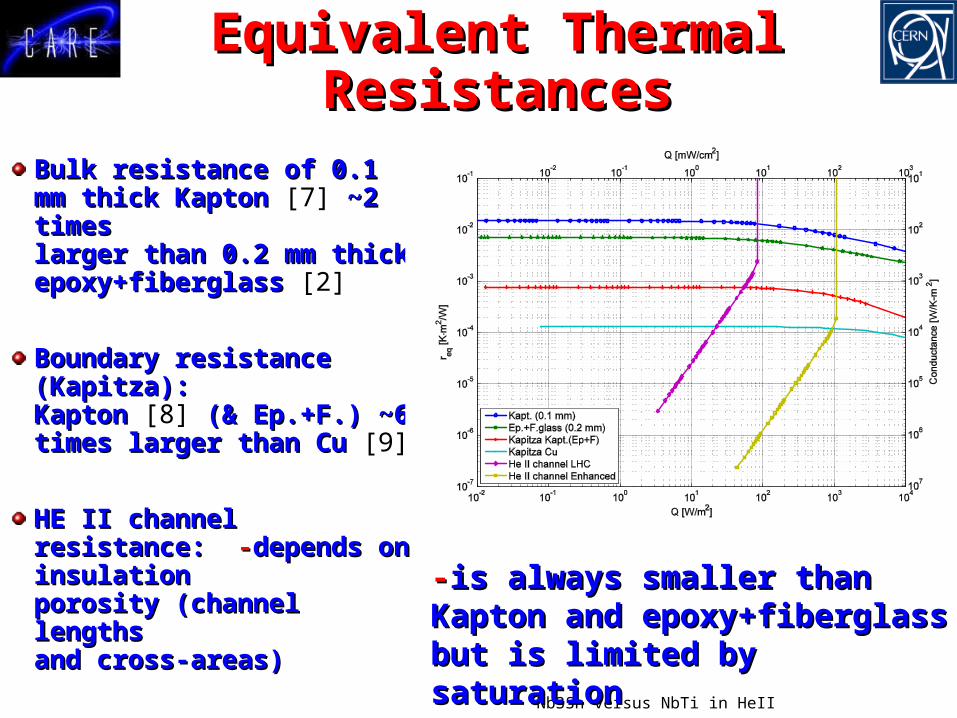
Equivalent Thermal Equivalent Thermal ResistancesResistances
Bulk resistance of 0.1 Bulk resistance of 0.1 mm thick Kapton mm thick Kapton [7] ~2 ~2 times times larger than 0.2 mm larger than 0.2 mm thick epoxy+fiberglass thick epoxy+fiberglass [2]
Boundary resistanceBoundary resistance(Kapitza):(Kapitza):Kapton Kapton [8] (& Ep.+F.) (& Ep.+F.) ~6~6times larger than Cu times larger than Cu [9]
HE II channel HE II channel resistance: resistance: --depends depends on insulationon insulationporosity (channel porosity (channel lengthslengthsand cross-areas)and cross-areas)
--is always smaller than is always smaller than Kapton and Kapton and epoxy+fiberglass but is epoxy+fiberglass but is limited by saturationlimited by saturation

Davide Tommasini Nb3Sn versus NbTi in HeII THERMOMAG-07, Paris 19 November 2007
Experimental Experimental (B. Baudouy et al (B. Baudouy et al
Cryogenics 39, 921 (1999)
SSC dipole
LHC dipole
SolidConductionSuperfluid
Conduction
Predominance:

Davide Tommasini Nb3Sn versus NbTi in HeII THERMOMAG-07, Paris 19 November 2007
Comparison for Operating Comparison for Operating Conditions:Conditions:
SameSame or or SpecificSpecific
1.1. We consider two coils in a He II bath (We consider two coils in a He II bath (TTbb=1.9=1.9) :) :1.1. NbNb33Sn with Sn with sealed sealed insulationinsulation
2.2. Nb-Ti with Nb-Ti with porous porous insulationinsulation
2.2. We impose the We impose the samesame eng-eng-ineering current density ineering current density JJengeng
and operative peak field and operative peak field BB
3.3. We get the temperature margin We get the temperature margin T=TT=Tcc-T-Tbb we we combine it with the heat transfer correlations combine it with the heat transfer correlations and we obtain the corresponding heat fluxand we obtain the corresponding heat flux
2.2. We impose We impose JJ and and BBultult
specificspecific of their of their practical usepractical use

Davide Tommasini Nb3Sn versus NbTi in HeII THERMOMAG-07, Paris 19 November 2007
0 0.5 1 1.5 2 2.5 3 3.57
7.5
8
8.5
9
9.5
10
10.5
11
11.5
12
T Nb-Ti [K]
T
Nb 3S
n [K
]Temperature Margin (T=T
c-T
b) Comparison for 9 T Peak Field
J c,en
g [A
/mm
2 ]
0
103
205
307
409
511
613
715
817
919
Temperature Margin Temperature Margin Comparison for Comparison for Same B (9T) Same B (9T)
and Jand Jengeng
Tb=1.9
Cu/ScNb-Ti 1.5Nb3Sn 1

Davide Tommasini Nb3Sn versus NbTi in HeII THERMOMAG-07, Paris 19 November 2007
Maximum Heat Flux for Maximum Heat Flux for Same B (9T) and JSame B (9T) and Jengeng
0 500 1000 1500 2000 2500 30000
50
100
150
200
250
300
350
Jeng
[A/mm2]
Q [
W/m
]
IR Quad
LHC MainEnhanced
Bare
Nb3Sn
Cu/ScNb-Ti 1.5Nb3Sn 1
Bare cable asymptotic limit
Nb3 Sn Enhanced
SSC dipole
LHC dipole
SSC dipoleLHC dipoleEnhancedBare cableNb3Sn

Davide Tommasini Nb3Sn versus NbTi in HeII THERMOMAG-07, Paris 19 November 2007
Maximum Heat Flux for Maximum Heat Flux for SpecificSpecific ConditionsConditions
0 0.2 0.4 0.6 0.8 10
20
40
60
80
100
120
140
160
180
200
220
J/Jc(T
b,B
ult) [A/mm2]
Q [
W/m
]
Bare
cab
le a
symp
totic lim
it
Nb3 Sn
Enhanced
SSCLHC MainJ/Jc (Tb,Bult)
B= 9 T for NbTiB= 9 T for NbTi
B= 13.5 T for Nb3SnB= 13.5 T for Nb3Sn

Davide Tommasini Nb3Sn versus NbTi in HeII THERMOMAG-07, Paris 19 November 2007
it corresponds to ~ 220 mW/m per it corresponds to ~ 220 mW/m per cable cable
it corresponds to ~830 mW/m it corresponds to ~830 mW/m per cable per cable

Davide Tommasini Nb3Sn versus NbTi in HeII THERMOMAG-07, Paris 19 November 2007
Enhanced porosityEnhanced porosity

Davide Tommasini Nb3Sn versus NbTi in HeII THERMOMAG-07, Paris 19 November 2007
Porosity checker/1Porosity checker/1
Air enters the stack of cable longitudinally (A) and can Air enters the stack of cable longitudinally (A) and can exit longitudinally (C), without crossing the insulation exit longitudinally (C), without crossing the insulation or radially (B) crossing the insulation. or radially (B) crossing the insulation.
Insulation porosity is evaluated from the Insulation porosity is evaluated from the comparison between radial and longitudinalcomparison between radial and longitudinalflowflow
A C
BB
Flow out (B)
Flow in (A)
Flow out (C)

Davide Tommasini Nb3Sn versus NbTi in HeII THERMOMAG-07, Paris 19 November 2007
Porosity checker/2Porosity checker/2

Davide Tommasini Nb3Sn versus NbTi in HeII THERMOMAG-07, Paris 19 November 2007
Tests Results/1Tests Results/1
Vertical compression 10 MPa

Davide Tommasini Nb3Sn versus NbTi in HeII THERMOMAG-07, Paris 19 November 2007
Tests Results/2Tests Results/2
Davide Tommasini Nb3Sn versus NbTi in HeII THERMOMAG-07, Paris 19 November 2007
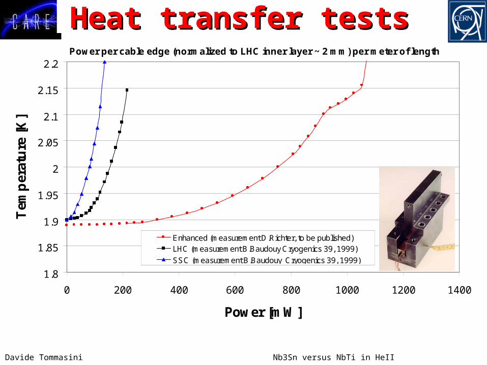
Heat transfer testsHeat transfer testsPower per cable edge (normalized to LHC inner layer ~ 2 mm) per meter of length
1.8
1.85
1.9
1.95
2
2.05
2.1
2.15
2.2
0 200 400 600 800 1000 1200 1400
Power [mW]
Tem
per
ature
[K
]
Enhanced (measurement D.Richter, to be published)LHC (measurement B.Baudouy Cryogenics 39, 1999)
SSC (measurement B.Baudouy Cryogenics 39, 1999)

Davide Tommasini Nb3Sn versus NbTi in HeII THERMOMAG-07, Paris 19 November 2007
ConclusionsConclusions For same For same BB and and JJengeng, Nb, Nb33Sn coils made by Rutherford Sn coils made by Rutherford
cables can draw one order of magnitude more heat than cables can draw one order of magnitude more heat than typical Nb-Ti coils typical Nb-Ti coils
For the same margin to critical surface (specific For the same margin to critical surface (specific operating conditions), Nboperating conditions), Nb33Sn coils made by Rutherford Sn coils made by Rutherford cables can draw three times more heat than typical LHC cables can draw three times more heat than typical LHC Nb-Ti coils Nb-Ti coils
……however…however…there is a large potential to increase the dimension of there is a large potential to increase the dimension of the cooling channels thus moving their saturation at the cooling channels thus moving their saturation at
higher heat fluxeshigher heat fluxes
The use of this potential in HeII provides a The use of this potential in HeII provides a spectacular increase of heat evacuation spectacular increase of heat evacuation
capabilities of NbTi coils competing/exceeding capabilities of NbTi coils competing/exceeding NbNb33Sn @ fields below 9 TSn @ fields below 9 T

Davide Tommasini Nb3Sn versus NbTi in HeII THERMOMAG-07, Paris 19 November 2007
ReferencesReferences
1. C. Meuris, B. Baudouy, D. Leroy, B. Slezess, Heat transfer in electrical insulation of LHC cables cooled with superfluid Helium, Cryogenics 39, 921 (1999)
2. L. Imbasciati et al.,Thermo-mechanical Characterization of Insulated and Epoxy-Impregnated Nb3Sn composites, IEEE Trans. on Appl. Supercond., Vol. 13, Issue 2, 1788 (2003)
3. D.S. Matsumoto, C.L. Reynolds Jr., A.C. Anderson, Thermal Boundary Resistance at Metal Epoxy Interfaces, Phys. Rev. B, Vol. 16 n.8, 15 Oct. 1977.
4. F. Rondeaux, P. Bredy, J.M. Rey, Thermal Conductivity Measurements of Epoxy Systems at Low Temperatures, Adv. Cryo. Eng. 48A (Materials), 197 (2002)
5. J. Gorter, J. H. Mellink, On the Irreversible Processes in Liquid Helium II, Physica 15, 285 (1949)
6. V. Arp, Heat transport through Helium II, Cryogenics 10, 96 (1970)7. J. Lawrence, A.B. Paterl, J.G. Brisson, The Thermal Conductivity of Kapton HN between
0.5 and 5 K, Cryogenics 40, 203 (2000)8. B. Baudouy, Kapitza Resistance and Thermal Conductivity of Kapton in Superfluid Helium,
Cryogenics 43, 667 (2003) 9. A. Kashani, S.W. Van Sciver, Kapitza Conductance of Technical Copper with Several
Different Surface Preparations, Cryogenics 25, 238 (1985)10. E. Todesco, J.P. Koutchouk, Scaling Laws for * in the LHC Interaction Regions, CARE
Workshop LUMI-06, 17th October 2006, Valencia, Spain.11. N. Kimura et al., Heat Transfer from Insulated Rutherford Type Cables Immersed in
Pressurized He II, Adv. Cryo. Eng. 43