datacad 12 smart entities tutorial
TRANSCRIPT

Smart Entities Tutorial
Smart Entities Tutorial ............................................................................. 1
Getting Ready to Draw ............................................................................ 2
Working with Smart Walls ....................................................................... 4
Customize the Exterior Walls ............................................................................................... 4
Draw the Exterior Walls ........................................................................................................ 6
Draw the Interior Walls ......................................................................................................... 8
Working with Smart Doors .................................................................... 10
Customizing and Installing the Entry Door ..................................................................... 11
Installing Office and Drying/Storage Room Doors .......................................................... 12
Selecting and Installing the Studio Door ........................................................................... 14
Working with Smart Windows ............................................................... 16
Customizing and Installing Studio Windows .................................................................. 17
Installing Other Windows ................................................................................................... 18
Making Changes .................................................................................... 23

2
Smart Entities Tutorial This tutorial introduces you to the concepts and advantages of using DataCAD’s smart entities to create the walls, doors, and windows in your design project.
We will design a studio for an artist who specializes in oil portraits and still life studies. He needs abundant light, a northern exposure, space to store his supplies, a place to safely dry his finished work, and an area where clients can pose comfortably. Basically, he needs to get away from the distractions of his young family, but wants to be close enough to respond in an emergency. Since cost is a major consideration, he prefers using stock material rather than custom doors and windows as much as possible.
Getting Ready to Draw We will start a new file for the studio, select an input mode (coordinate system), and establish layers.
Start DataCAD and begin the drawing file:
1. Click on Start, Programs, DataCAD 12 to display the DataCAD 12 program group.
2. Click on DataCAD 12. The program opens.
Shortcut: If you have a DataCAD 12 icon on your desktop, you can simply double-click on that to start the program.
3. Select New from the File pull-down menu. A dialog box appears. Notice that DataCAD automatically supplies a generic entry in the File name field to make sure all your creations will be saved even if you forget to give it a distinctive title.
4. Highlight the existing file name and type Artist Studio in the File name field.
5. Click on Create or press [Enter]. Your file name appears on the title bar above the standard toolbars, menu options, and a blank drawing window.
Figure 1 New File Dialog

3
Set the input mode:
Figure 2 Set the input mode via the tools pull-down menu
Highlight Input Mode in the Tools pull-down menu, slide to the right, and click on Direction/Distance.
Or press [Insert] several times until the message on the Attention toolbar says Current input mode = Direction, Distance.
Figure 3 Input Mode Drop-down List
Or select Dir. Distance from the Status toolbar located above your drawing window.
Establish layers for your drawing:
1. Open the Layer Manager, using one of the following methods:
• Select Layer Manager from the Tools pull-down menu.
• Or press [Ctrl] + [L].
• Or select Layers from the Utility menu and click on Manage.
• Or click on the Layer Manager button on the Status toolbar.
2. Rename the first layer by double-clicking on Layer001, typing Walls, and pressing [Enter].
Hint: Smart walls must be on the same layer so that the intersections will clean. If you put exterior walls and interior walls on separate layers, the intersections cannot clean.
3. Create two new layers (in addition to the one that DataCAD supplies) by clicking on the New icon, typing 2 in the input field, and pressing [Enter].
4. Name the new layers Doors and Windows.
5. Click on the All On icon to set all three layers on.

4
6. Make sure the green light is on for the Walls layer. If it isn’t, highlight the Walls layer and click on Set Active.
7. Make sure all layers are unlocked. If the red padlock appears for any layer, just click on the icon to unlock it.
Figure 4 Layer Manager
8. Click on OK when your Layer Manager looks like this example.
Save your settings:
Select Save from the File pull-down menu.
Or press [Ctrl] + [S].
Save your work when you are satisfied with what you accomplished while you are developing your design. This will make recovery a less daunting task if you make a mistake along the way. It’s wise to save often just in case there’s a power surge or your office temporarily loses electricity.
Working with Smart Walls We will work with two basic types of walls for the artist’s studio: exterior and interior. First, we will make modifications, save our changes with a distinctive name, load our wall, and set it active. Next, we will draw the customized exterior walls. Finally, we will add interior walls using the default wall DataCAD supplied.
Customize the Exterior Walls Load the exterior walls:
1. Select Architect from the Edit menu.
2. Toggle on Auto 3D in the Walls menu.

5
3. Select Manage in the Walls menu. This opens the Wall Type Manager.
4. Highlight 2x4_Clapboard and click on Load. The formerly greyed-out
wall, line, display/rendering, caps, and openings options are now available for you to customize.
Customize exterior wall options and save your settings:
1. Leave the wall properties, line properties, and caps and openings options alone.
2. Change the Material in the Display/Rendering Attributes section of the Wall Type Manager for Line 1:
• Make sure 1 appears in the Line field in the Line Properties portion.
• Make sure Outside appears in the Control Line field. This means that you will be drawing the exterior wall based on the outside line, not the inside one.
• Click on Load. The Load Material File dialog box appears.
• Display the Wood Siding folder in the Look in field. To reach this folder, double-click on Siding from the Materials folder, then double-click on Wood in the Siding folder, and finally double-click on BarnBoard100.ini. Notice that BarnBoard100 is now shown in the Material field.
3. Change the Color and Material in the Display/Rendering Attributes section of the Wall Type Manager for Line 2:
• Select 2 from the Line pull-down menu in the Line Properties portion of the Wall Type Manager. The options for line 2 appear in the Wall Type Manager.
Notice that the Offset from previous line can be changed. For a 2-line wall such as this, the line 2 offset is equal to the width in the Wall Properties section. If you change the value in the Offset field, the width will change to that value, too.
• Clear the Use current settings box (make sure there is no check mark in the box). This lets you make decisions about Display/Rendering Attributes. If you leave this box checked, your interior wall drawing line will be the same as your layer’s color (in this case, white).
• Select Green from the pull-down Color menu. The line used in the 2D drawing will now be green, instead of white.
• Click on Load. The Load Material File dialog box appears.

6
• Display the Yellow folder in the Look in field. To reach this folder, click on the Up One Level icon until you see Materials in the Look in field. Double-click on Matte from the Materials folder, then double-click on Yellow in the Matte folder, and finally double-click on Deco_Peach_Matte.ini. Notice that Deco_Peach_Matte is now shown in the Material field. Look in the preview window to get an idea of what the exterior wall will look like in your drawing.
4. Save the customized exterior wall type:
• Click on Save As . . . to open the Enter wall type filename dialog box. The Wall Types folder appears in the Save in field.
• Type AS Exterior Wall in the File name field.
• Click on Save or press [Enter] to save AS Exterior Wall to the hard drive. DataCAD saves the changes to the AS Exterior Wall type definition file on the hard drive, and automatically loads it in the current drawing and sets it active.
Figure 5 Wall Type Manager
5. Click on OK to exit the Wall Type Manger.
Draw the Exterior Walls Set trim and clean options:
1. Make sure the Architect/Walls menu is displayed.
2. Make sure Auto 3D is toggled on.
3. Make sure Trim In is toggled on to automatically trim interior lines at intersections.
4. Make sure Clean is toggled on to automatically clean walls at intersections.
Draw the exterior walls of the artist’s studio:
1. Make sure you are on the Walls layer and that Dir. Distance is the input method shown in the Status toolbar.

7
2. Select AS Exterior Wall from the Types toolbar.
3. Place your cursor in the drawing window (about an inch in from the left
and in inch down from the top) and click your left mouse button once.
4. Move your cursor toward the right and press [Spacebar]. This confirms that you want to draw the first wall going from the left to the right. You are prompted to Enter relative distance.
5. Type 16 and press [Enter]. DataCAD extends the wall to 16 feet to the right of where you were in step 3. You are prompted to Click a point to define the inside of the wall.
6. Click below the line. Notice that the line has changed into a 2-line wall. The upper (exterior) line is yellow and the interior (lower) line is green, just as we defined the attributes of AS Exterior Wall.
The 2-line wall is attached to the end of your cursor. As you move your mouse (and, by extention, your cursor), you are dragging the wall around at the same time. If you click the left mouse button, the wall acquires a corner. If you click the right mouse button, the wall is released from the cursor and DataCAD ends the wall. If you toggled Cap on, there would be a cap at each end of the wall; if you toggled Clean on, there would be no cap at each end of the wall.
7. Move your cursor downward at a 90-degree angle, press [Spacebar], type 24, and press [Enter]. This completes the second wall.
8. Move your cursor toward the left at a 90-degree angle, press [Spacebar], type 16, and press [Enter]. This completes the third wall.
9. Move your cursor upward at a 90-degree angle, press [Spacebar], type 24, and press [Enter]. This completes the fourth wall.
10. Right-click once to end the exterior walls.

8
11. Save your drawing by pressing [Ctrl] + [S]. File save (BACKUP) complete
appears on the Attention toolbar.
Draw the Interior Walls We will use the default 2-line wall DataCAD provides for the interior walls. The studio will be on the north (top) portion of the building. The rooms on the south (bottom) end will be used for drying paintings, office space, and storage.
Select the default 2-line wall:
1. Make sure Auto 3D is toggled on in the Architect/Walls menu.
2. Make sure Trim In and Clean are toggled on.
3. Select 2 Line (Default) from the pull-down menu beside the Wall Type Manager button on the Types toolbar.
Draw the first interior wall, dividing the building in half:
1. Move your cursor down along the green line (inside) of the left wall until you see the dynamic snap indicator for Midpoint.
2. Snap to the Midpoint of the green line using the middle mouse button or the [N] key on the keyboard to start your interior wall.
3. Slide your cursor to the right until you get to the green line on the right side of the building.

9
4. Snap to the midpoint of this wall to end the interior wall which divides the room in half. You are prompted to Click a point to define the inside of the wall.
5. Click once below the line.
6. Right-click to end the interior wall. This releases the 2 Line (Default) wall from your cursor.
Divide the lower half of the building into two rooms:
1. Move your cursor to the Midpoint dynamic snap indicator of the interior wall you just drew.
2. Snap to the Midpoint of the default interior wall.
3. Slide your cursor downward at a 90-degree angle until you get to the green line on the bottom of the building.
4. Snap to the midpoint of this wall. You are prompted to Click a point to define the inside of the wall.
5. Click once to the left of the line.
6. Right-click to end the interior wall and release the 2 Line (Default) wall from your cursor.
Divide the lower right room into two portions:
1. Insert a reference mark at the bottom right corner of the building:
• Place your cursor at the bottom right corner of the building on the endpoint of the green lines.
• Press the [`] key (just below the [Esc] key on most keyboards).
• Toggle Draw Marks on in the Ref. Point menu. You are prompted to Click reference point.
• Snap to the inside bottom right corner where the green lines meet. DataCAD places a tiny X at that point and prompts you to Indicate the reference angle.
• Slide your cursor up the right green line and press the left mouse button to indicate that you want to use a 90-degree angle. (You will see a: 90-0’ on the Coordinates/Hints toolbar.)
• Press [Spacebar], type 8 when prompted to Enter relative distance, and press [Enter]. This places the cursor 8 feet above the inner right corner to let you start drawing your wall.
2. Slide your cursor straight across toward the left. Stop when you reach the wall that divides the bottom of the building into two rooms.
3. Click once to stop drawing the wall segment. You are prompted to Click a point to define the inside of the wall.
4. Click once below the line.
5. Right-click to end the interior wall.

10
Working with Smart Doors Now that the smart walls are up, it’s time to add some doors to the building. We will begin with a customized entry door. Then, we will add doors to the office (the smallest room), the drying/storage room, and the studio.
We will place all the doors on the Doors layer. Corresponding openings will automatically be inserted in the smart walls that are located on the Walls layer.
Before we work with the doors, let’s change the scale and the snap grid.
Change the scale:
1. Go to the Status toolbar and click on the pull-down menu beside the Layer search icon.
2. Select 3/8” from the Scale pull-down menu. Notice that the artist’s studio that you drew at 1/4” scale is now larger. You can use your arrow keys to reposition the larger image so that it fits in your drawing window.
Switch to the Doors layer:
1. Select Doors from the pull-down menu beside the Layer Manager button on the Status toolbar.
Change the snap grid:
1. Go to the Utility menu and click on Grids.
2. Click on Grid Size in the Grids menu.
3. Click on Set Snap in the Grid Size menu.

11
4. Select 1” from the Set Snap menu. Snap grid setting: grid size = 1” by 1” appears in the Attention toolbar.
5. Press [A] to display the Walls menu again.
Customizing and Installing the Entry Door Customize the entry door:
1. Open the Door Types Manager by clicking on the Open Door Type Manager button on the Types toolbar. The Door Type Manager appears.
If this is the first time you are using DataCAD’s smart doors, the 3068 (Default) door may be the only option in the menu. Make sure there is a checkmark in Display External Types box. Then click on the File folder, double-click on Door Types from the Support Files folder, click on Hinged from the Frenchwood subfolders, and click on OK. The Frenchwood hinged doors appear in the Door Type Manager.
2. Select the basic door you want to customize:
• Scroll down and highlight FWH3168A.
• Click on Load. As DataCAD loads the Door Type into the drawing, it also sets it active, as indicated by the red text.
3. Change Knob characteristics:
• Click on the Knob tab.
• Make sure Use Symbol is toggled on.
• Click on the Folder button under Use Symbol. From the Symbols folder, select Door Types, choose Door Knobs, and double-click on Neptune2.dsf.
4. Change Swing characteristics:
• Click on the Swing tab.

12
• Toggle Match Door Color off (no checkmark) and select Magenta from the Color pull-down menu.
• Change Swing Angle 2D to 60.
• Change Swing Angle 3D to 60.
5. Select Save As . . ., type AS Entry Door in the File name field, and press
[Enter]. The door you customized is now included in the available list of doors. It is also loaded into the drawing and set active.
6. Click on OK. This closes the Door Type Manager and opens the Doors menu. “Active Door Type: AS Entry Door” appears on the Attention toolbar.
Place the AS Entry Door into the building:
1. Make sure the Doors menu is open.
2. Toggle off Sides. Make sure Center Point, Cut Wall, At Sill, and Any Layer are toggled on. You are prompted to Click center of door.
3. Hover your cursor along the right exterior wall by the hallway portion until you see the dynamic snap indicator for Midpoint.
4. Snap to the Midpoint. The door appears in the smart wall. You are prompted to Click the strike side of the door and indicate direction of door swing.
5. Click outside the building to make the door swing outward.
Installing Office and Drying/Storage Room Doors For these two rooms, we will use the default door customized with a lever-type door knob.

13
Add a lever-type door knob to the default door:
1. Make sure you are on the Doors layer (look at your Status toolbar, next to the Layer Manager button). If you aren’t, select Doors from the pull-down menu on the Status toolbar.
2. Open the Door Types Manager by clicking on the button on the Types toolbar. The Door Type Manager appears.
3. Click on 3068 (Default).
4. Select the Knob tab.
5. Toggle on Use Symbol. The list of available door knob symbols appears. (If it doesn’t appear automatically, just click on the folder below the check box.)
6. Highlight Neptune.dsf in the Symbols\Door Types\Door Knobs folder and press [Enter].
7. Select Save As . . ., type AS Interior Door in the File name field, and press [Enter].
8. Click on OK.
Install the door by its center into the drying/storage room:
1. Make sure Sides is toggled off in the Doors menu. You are prompted to Click center of door.
2. Snap to the midpoint of the wall at the end of the hallway. The door appears in the smart wall. You are prompted to Click direction of door swing.
3. Click inside the drying/storage room so the door hinge opens into the room.
Install the door by its sides into the office:
1. Toggle on Sides in the Doors menu. You are prompted to Click hinge side of door.
2. Click at the end of the hallway just a little to the right on the top office wall. The door appears in the smart wall. You are prompted to Click strike side of door and indicate direction of door swing.
3. Click inside the office.

14
Since the interior door to the drying/storage room is too big to fit in the wall, let’s change the properties of the door type.
Change the properties of the AS Interior Door:
1. Go back to the Door Type Manager.
2. Make sure AS Interior Door is active and display the Unit tab.
3. Change the Fixed Width of the unit to 2.4 and click OK. Notice that both doors (the one to drying/storage and the one to the office) change because they both use the same type definition.
Selecting and Installing the Studio Door Let’s make this door a little fancier than the other interior doors.
Select and load the studio door:
1. Click on the Door Manager button on the Types toolbar. The Door Type Manager appears.
1. Click on the folder just above the New button. The Door types folder opens.
2. Highlight Gliding (instead of Hinged) and click OK. The gliding doors appear in the Door Type Manager.
3. Highlight FWG5068 and click Load.
4. Click on Save As . . ., type AS Gliding Door, and press [Enter].
5. Click OK.
15
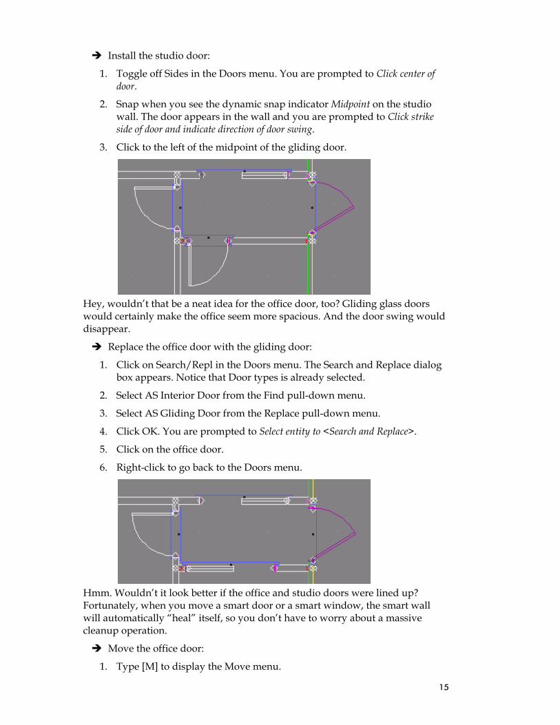
Install the studio door:
1. Toggle off Sides in the Doors menu. You are prompted to Click center of door.
2. Snap when you see the dynamic snap indicator Midpoint on the studio wall. The door appears in the wall and you are prompted to Click strike side of door and indicate direction of door swing.
3. Click to the left of the midpoint of the gliding door.
Hey, wouldn’t that be a neat idea for the office door, too? Gliding glass doors would certainly make the office seem more spacious. And the door swing would disappear.
Replace the office door with the gliding door:
1. Click on Search/Repl in the Doors menu. The Search and Replace dialog box appears. Notice that Door types is already selected.
2. Select AS Interior Door from the Find pull-down menu.
3. Select AS Gliding Door from the Replace pull-down menu.
4. Click OK. You are prompted to Select entity to <Search and Replace>.
5. Click on the office door.
6. Right-click to go back to the Doors menu.
Hmm. Wouldn’t it look better if the office and studio doors were lined up? Fortunately, when you move a smart door or a smart window, the smart wall will automatically “heal” itself, so you don’t have to worry about a massive cleanup operation.
Move the office door:
1. Type [M] to display the Move menu.

16
2. Select Drag and toggle on Entity. You are prompted to Select entity to <MOVE>.
3. Click on the left edge of the sliding door to the office. The door becomes a set of dashed lines. You are prompted to Click the point to drag from.
4. Click on the sliding door again. Notice that it is now attached to your cursor, so you can move it anywhere. You are prompted to Click new position for this entity.
5. Move your cursor to the right along the wall until you have lined up the office and studio doors; then click. The smart wall has cleaned itself up around the repositioned sliding door.
6. Right-click twice to exit the Drag and Move menus.
Look at your building in the Object Viewer:
1. Select the colored cube in the Viewer toolbar. The Object Viewer opens.
2. Twirl the building around, peek into the rooms, and click X when you’re
finished. Note that door openings can have different representations in 2D and 3D.
Save those walls and doors:
1. Press [Ctrl-S].
Working with Smart Windows

17
If there’s one thing artists want, it’s plenty of light – especially from the north! One of the artist’s friends owns a window distribution outlet and is willing to give him a tremendous discount, so our client can afford to get as many windows as he wants.
Customizing and Installing Studio Windows Select the window that you want to customize:
1. Make sure the Windows layer is the active layer by selecting Windows from the Layer Manager pull-down menu on the Status toolbar.
2. Make sure Auto 3D is toggled on in the Architect/Walls menu.
3. Select Windows from the Walls menu.
4. Select Manage from the Windows menu. The Window Type Manager appears.
5. Click on the folder below the list of windows.
6. Click on Window Types, select Fixed, and click OK. The fixed windows appear in the Window Type Manager.
7. Highlight P5060 and click on Load.
8. Select the Unit tab.
9. Change Height to 7.0, change Head Height to 7.6, and press [Tab] to move to the next field on the panel. Notice that Sill Height automatically changes to 0.6 based on the Unit Height and Head Height settings.
10. Select Save As . . ., type AS Fixed Window in the File name field, and press [Enter].
11. DataCAD saves out the Window Type file, hen automatically loads it in the drawing and sets it active. Click on OK to dismiss the Window Type Manager.
Install the customized window into the north wall of the studio:
1. Select AS Fixed Window from the pull-down menu beside the Window Type button on the Types toolbar. Active Window type: AS Fixed Window appears on the Attention toolbar.

18
2. Toggle off Sides in the Windows menu.
3. Toggle on Center Point, Cut Wall, and Any Layer. You are prompted to Click center of window.
4. Put your cursor near the Midpoint of the north wall of the studio. Notice that the Dynamic snap indicator finds the midpoint and displays the tooltip. Snap to this point. The window appears in the middle of the north wall.
Installing Other Windows Load casement windows for the studio:
1. Select Manage from the Windows menu. The Window Type Manager appears.
2. Click on the folder below the list of windows.
3. Select Casement from the Window Types folder and click OK.
4. Highlight CX14 and click on Load.
5. Select Casement from the Unit Type pull-down menu.
6. Select the Glass tab and change Thickness to 0.0.1/2, Horizontal Panes to
2, and Vertical Panes to 3.
7. Click on Save As…, name the window AS CX14.win, and press [Enter].
8. DataCAD saves out the Window Type file, loads it into the drawing, and sets it active. Click on OK to dismiss the Window Type Manager.

19
Install AS CX14 casement windows in the studio walls:
1. Make sure you are on the Windows layer.
2. Make sure AS CX14 is the active window type.
3. Make sure Sides is toggled off. Toggle on Center Point, Cut Wall, and Any Layer. You are prompted to Click center of window.
4. Find the Midpoint on the north wall to the left of the fixed window. Snap once to install the AS CX14 casement window.
5. Find the Midpoint on the north wall to the right of the fixed window. Snap once to install the AS CX14 casement window.
6. Find the Midpoint on the left wall of the studio. Snap once to install the AS CX14 casement window.
7. Install the AS CX14 casement window at the Midpoint on the left wall above and below the window you just installed.
Use Mirror to copy the windows from the left wall to the right wall:
1. Press [Alt-M] to open the Mirror menu. You are prompted to Click first point along the line of reflection.
2. Snap to the Midpoint on the north wall. You are prompted to Click second point along the line of reflection.
3. Drag your cursor straight downward and click again. A dashed grey line divides the drawing.
4. Toggle on And Copy in the Mirror menu.
5. Toggle on Area in the Mirror menu. You are prompted to Select first corner of area to <MIRROR>.

20
6. Click just above the top of the three windows on the left wall. You are prompted to Click second corner of area to <MIRROR>.
7. Drag downward and to the right until the rubberband surrounds all three windows on the left wall.
8. Click when you finish drawing the rubberband. The windows are copied
onto the right wall.

21
9. Right-click to leave the Mirror menu. The reflection line disappears and
you are back in DataCAD’s Windows menu.
Install awning windows in the drying/storage room:
1. Select Manage from the Windows menu to open the Window Type Manager.
2. Click on the folder below the list of windows.
3. Select Awning from the Window Types folder and click OK.
4. Highlight AN281 click on Load.
5. Click on OK to dismiss the Window Type Manager.
6. Install three AN281 windows on the left wall much like the CX14 ones by snapping to the middle of the wall, then above and below the central window.
7. Install two more AN281 windows on the lower storage room wall.

22
Install CW24 casement windows in the office:
1. Make sure Center Point, Cut Wall, and Any Layer are toggled on in the Windows menu. Toggle off Sides.
2. Open the Window Type Manager, click the folder above the New button, select Casement from the Window types folder, and press click OK. The casement windows appear in the Window Type Manager.
3. Highlight CW24, click on Load, and make sure Casement is selected from the Unit Type pull-down menu on the Unit tab.
4. Click OK. You are prompted to Click center of window.
5. Snap to the midpoint on the lower office wall. The window appears on the lower wall.
6. Snap to the midpoint on the right office wall. The window appears on the right wall.
Save your drawing:
1. Press [Ctrl-S] to save everything to the Artist Studio file.

23
Making Changes Hmm . . . That office looks awfully teensy weensy, doesn’t it? How can our client fit his desk, chair, bookcase, and file cabinet in something that small? Let’s give him some more leg room.
Erase the office windows:
1. Press [E] to display the Erase menu.
2. Toggle on Entity and Layer Search. You are prompted to Select entity to <ERASE>.
3. Click on each window in the office. As each window disappears, the walls become whole again.
4. Right-click to get out of the Erase menu.
Enlarge the office:
1. Make sure you are on the Walls layer. If not, select Walls from the pull-down menu beside the Layer Manager button on the Status toolbar.
2. Make sure Auto 3D, Trim In, and Clean are toggled on in the Architect/Walls menu.
Although you can draw smart walls on any layer, they will clean only if they are on the Walls layer.

24
3. Select Edit Walls from the Walls menu.
4. Add nodes to the exterior office wall so they are 1’ from the current T intersections:
• Select Add Node from the Edit Walls menu. You are prompted to Select wall edge to add node to.
• Select the bottom wall of the office.
• Put your cursor near the lower corner (inside the office, near the intersection of the default and AS Exterior Wall), press [`] to add a reference point, press [N] or click the middle mouse button to position the reference point in the corner, drag your cursor to the right and click to show that you want a 0-degree angle, press [Spacebar], type 1, and press [Enter]. The new node appears.
• Select the right wall of the office.
• Put your cursor near the upper corner (inside the office, near the intersection of the default and AS Exterior Wall), press [`] to add a reference point, press [N] or click the middle mouse button to position the reference point in the corner, drag your cursor downward and click to show that you want a 270-degree angle, press [Spacebar], type 1, and press [Enter]. The new node appears.
5. Drag the exterior office walls to make the room bigger:
• Press [M] to open the Move menu, select Drag, and toggle on Entity and Multiple in the Drag menu.
• Click on the lower exterior wall near the right corner, then click on the right exterior wall near the right corner. These wall segments are now grey dashed lines.
25
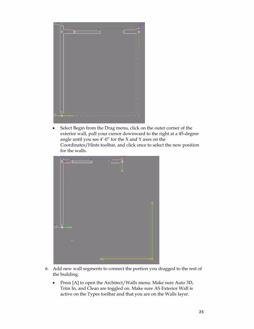
• Select Begin from the Drag menu, click on the outer corner of the
exterior wall, pull your cursor downward to the right at a 45-degree angle until you see 4’-0” for the X and Y axes on the Coordinates/Hints toolbar, and click once to select the new position for the walls.
6. Add new wall segments to connect the portion you dragged to the rest of
the building.
• Press [A] to open the Architect/Walls menu. Make sure Auto 3D, Trim In, and Clean are toggled on. Make sure AS Exterior Wall is active on the Types toolbar and that you are on the Walls layer.

26
• Click near the endpoint of the outer right wall, pull your cursor upward until the control line is almost opposite the node where you broke the original exterior office wall, click once.
• Drag your cursor to the left of the control line and click to indicate the inside of the wall.
• Drag your cursor to the left to continue the wall after the corner. Click when the control line almost meets the original exterior office wall.
• Right-click to stop drawing the wall.
7. Join the new wall segments to the existing walls:
• To fix the L intersection, select Cleanup from the Edit menu and choose L Intersect; click near the lower junction of the two segments, drag the area box diagonally upward to the right above the segments, and click again to end the box.
• To join the broken straight wall segments, right-click to return to the Cleanup menu and select Weld Wall; click outside near the lower wall segment, drag the area box diagonally upward to the left above the upper wall segment, and click again to end the box.
Warning: If you were not on the Walls layer when you drew the wall segments, the L intersection and Weld functions will not clean properly.

27
• Follow the same principle to connect the lower office wall segment to
the original exterior office wall.
Let’s put four windows in those new office walls. To save time, we’re just going to “eyeball” their positions and place them by their sides. (You can move the windows if they don’t look good.)
Add windows to the expanded office:
1. Press [A] to go to the Architect/Walls menu. Make sure Auto 3D, Trim In, and Clean are toggled on.
2. Make sure you are on the Windows layer.

28
3. Select AS CX14 from the pull-down menu beside the Window Manager button on the Types toolbar.
4. Select Windows from the Walls menu.
5. Toggle on Sides, Cut Wall, and Any Layer. You are prompted to Click one jamb of window.
6. Place the windows in the new exterior walls:
• Click slightly to the right of the bottom left corner. Then click farther to the right to show where the second jamb should go.
• Click slightly to the left of the bottom right corner. Then click farther to the left to show where the second jamb should go.
• Click slightly below the upper right corner of the exterior office wall. Then click farther down to show where the second jamb should go.
• Click slightly above the bottom right corner. Then click farther up to show where the second jamb should go.
Save your drawing:
1. Press [Ctrl-S].

29
Your Artist Studio should now look like this in its 2D version:
Just select the colorful cube from the Viewer toolbar to open the Object Viewer. The 3D version of your drawing should look like this:

30
This completes the DataCAD 12 Smart Entities Tutorial.