data architecture reference model - wiscorp.com · this data architecture reference model document...
TRANSCRIPT
Data Architecture Reference Model
Whitemarsh Information Systems Corporation2008 Althea Lane
Bowie, Maryland 20716 Tele: 301-249-1142
Email: [email protected]: www.wiscorp.com
Data Architecture Reference Model
Table of Contents
1.0 Introduction . . . . . . . . . . . . . . . . . . . . . . . . . . . . . . . . . . . . . . . . . . . . . . . . . . . . . . . . . . . . . . . 1
2.0 Establishing the Right Data Architecture Terminology . . . . . . . . . . . . . . . . . . . . . . . . . . 2
3.0 The Whitemarsh Data Architecture Reference Model Components . . . . . . . . . . . . . . . . 43.1 Data Element Model . . . . . . . . . . . . . . . . . . . . . . . . . . . . . . . . . . . . . . . . . . . . . . . 73.2 Specified Data Model . . . . . . . . . . . . . . . . . . . . . . . . . . . . . . . . . . . . . . . . . . . . . . 93.3 Implemented Data Model . . . . . . . . . . . . . . . . . . . . . . . . . . . . . . . . . . . . . . . . . . 103.4 Operational Data Model . . . . . . . . . . . . . . . . . . . . . . . . . . . . . . . . . . . . . . . . . . . . 113.5 View Data Model . . . . . . . . . . . . . . . . . . . . . . . . . . . . . . . . . . . . . . . . . . . . . . . . . 133.6 XML Schema Data Model . . . . . . . . . . . . . . . . . . . . . . . . . . . . . . . . . . . . . . . . . . 14
4.0 Deployment of Data Architecture Models within Business Information SystemDevelopment . . . . . . . . . . . . . . . . . . . . . . . . . . . . . . . . . . . . . . . . . . . . . . . . . . . . . . . . . . 15
Copyright 2013, Whitemarsh Information Systems CorporationProprietary Data, All Rights Reserved
ii
Data Architecture Reference Model
1.0 Introduction
First things first: what is a reference model? From Wikipedia, a reference model is a model insystems, enterprise, and software engineering is an abstract framework or domain-specificontology consisting of an interlinked set of clearly defined concepts produced by an expert orbody of experts in order to encourage clear communication.
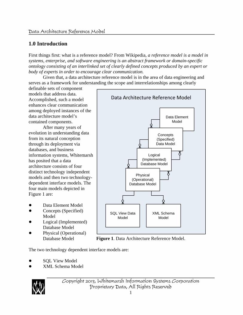
Given that, a data architecture reference model is in the area of data engineering andserves as a framework for understanding the scope and interrelationships among clearlydefinable sets of componentmodels that address data.Accomplished, such a modelenhances clear communicationamong deployed instances of thedata architecture model’scontained components.
After many years ofevolution in understanding datafrom its natural conceptionthrough its deployment viadatabases, and businessinformation systems, Whitemarshhas posited that a dataarchitecture consists of fourdistinct technology independentmodels and then two technology-dependent interface models. Thefour main models depicted inFigure 1 are:
! Data Element Model! Concepts (Specified)
Model! Logical (Implemented)
Database Model! Physical (Operational)
Database Model
The two technology dependent interface models are:
! SQL View Model! XML Schema Model
Data Element Model
Concepts (Specified)Data Model
Logical (Implemented)
Database Model
Physical (Operational)
Database Model
SQL View Data Model
XML Schema Model
Data Architecture Reference Model
Figure 1. Data Architecture Reference Model.
Copyright 2013, Whitemarsh Information Systems CorporationProprietary Data, All Rights Reserved
1
Data Architecture Reference Model
2.0 Establishing the Right Data Architecture Terminology
The data management industry, as a whole, commonly refers to the first grouping of models as:
! Conceptual! Logical! Physical
The problem with this generally accepted industry understanding is that is it presumes that thesemodels are three different forms of a same instance, that is, a Data Model. That is, for a givendata model for example, Marketing, there is the Marketing data model’s Conceptual Form, andthereafter, the Marketing data model’s Logical Form, and finally, the Marketing Model’sPhysical form.
A saying from H. L. Mencken comes to mind: For every complex problem there is ananswer that is clear, simple, and wrong. The problems with this understanding are:
! There is no concept of re-use of data-specified components within and across datamodels. Re-use is however very common.
! Because of this lack of re-use, there is a redundant set of design activities for the samedata-specified component across a multitude of the enterprise’s data models thatinevitably leads to unnecessary semantic differences, which, in turn, cause “dataproblems” that have plagued us for scores of years..
! There is a generally accepted relationship of one-to-many between Conceptual to Logicalto Physical. Not only is this inefficient and simply not born out in facts.
Because of the very closeness of the terminology,
Whitemarsh Data Component Data Management Industry Data Component
Concepts Conceptual Data Model
Logical Database Model Logical Data Model
Physical Database Model Physical Data Model
the terminology closeness inevitably leads to a conclusion of a “difference without distinction.”The distinctions that are both clear and significant include:
Copyright 2013, Whitemarsh Information Systems CorporationProprietary Data, All Rights Reserved
2

Data Architecture Reference Model
First the industry term, Conceptual Data Model is completely misleading within Whitemarshbecause the data management industry a Conceptual Data Model is a conceptual form of a datamodel. In Whitemarsh, a concept data model is simply the data model of an encapsulatingconcept. Thus, commonly existing within the data management industry, there would be aconceptual data model for Marketing that would contain whole collections of entities related toall the different aspects of marketing such as customers, locations including countries, states, andcities, marketing organizations including national, regional, districts, and the like, campaigns forsales and promotions, staffing results, contacts, products, and the like. Such a conceptual datamodel for Marketing could easily embrace several hundred entities.
In contrast, within Whitemarsh, a concept data model is simply the data model of aconcept. An example might be Address. There might be two subtypes for commercial andresidential. Another concept might be person name which would be Title, First Name, MiddleName, Last Name, and Name Suffix. These two examples illustrate that there is quite asignificant difference in scope and intent.
Second, the industry commonly employed terms, Logical and Physical Data Model, inaddition to being just two different development forms of the same “thing” (that is a data model),are without regard to the encapsulating concept, Database. A database is encapsulated in aSchema which is a “hard boundary” relationship mechanism that precludes syntacticallyexpressible relationships between tables in different schemas.
In addition to the “database” difference, within Whitemarsh, the terms Logical andPhysical connote technology independency differences. A Logical Database is without regards tothe technology dependancy on a DBMS vendor (i.e., Sybase vs DB2 vs Oracle). In contrast, a Physical Database is dependent on such bindings and/or restrictions.
In this regard, the ISO/ANSI standard for SQL is the controlling mechanism for LogicalDatabase model components while, for example, Sybase, DB2 or Oracle might be the controllingmechanism for Physical Database model components. This can be a difference with verydramatic distinctions as anyone knows who’s been acquainted withe SQL standards acrossSQL:1986 , SQL:1989 , SQL:1992 , SQL:1999 , SQL:2003 , SQL:2008, and SQL:2012.
The most dramatic difference is that first three SQL standard conformed more than not tothe relational model while there was a dramatic departure from the relational model starting withSQL:1999. Because of all these differences, Whitemarsh refers in all its materials as follows:
Data Model Type Whitemarsh Term
Concepts
Is referred to as the
Specified Data Model,
Logical Database Model Implemented DatabaseModel
Physical Database Model Operational DatabaseModel
Copyright 2013, Whitemarsh Information Systems CorporationProprietary Data, All Rights Reserved
3
Data Architecture Reference Model
3.0 The Whitemarsh Data Architecture Reference Model Components
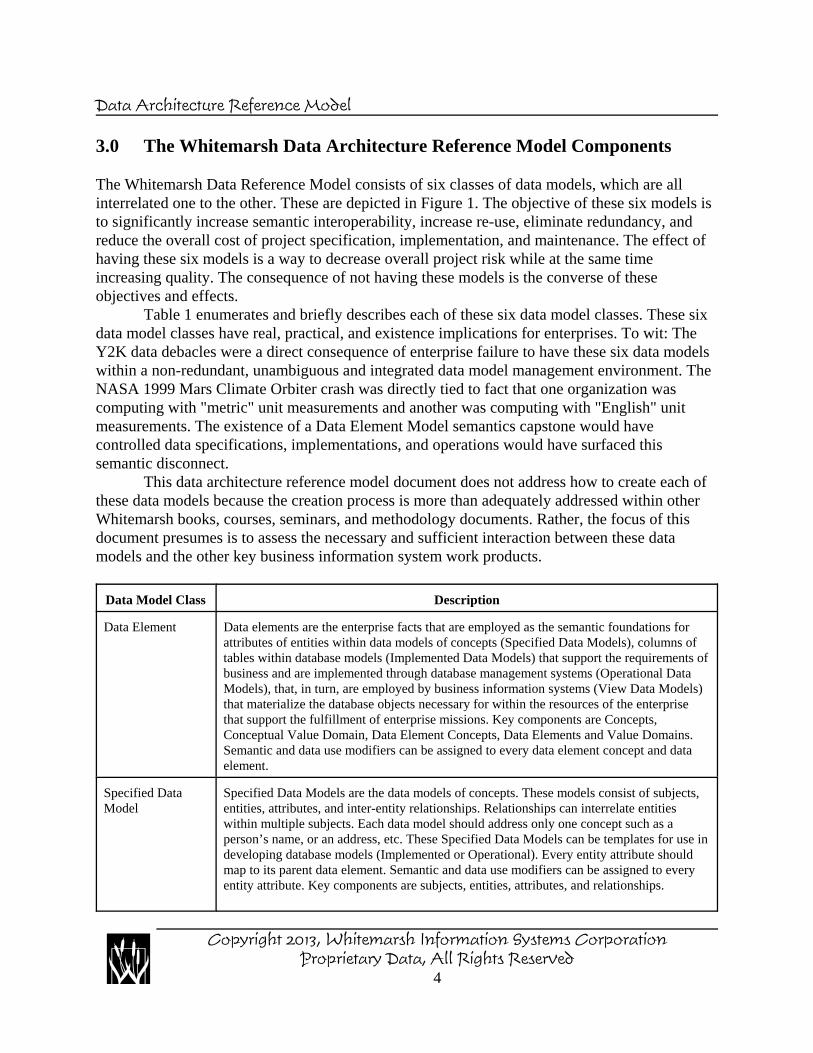
The Whitemarsh Data Reference Model consists of six classes of data models, which are allinterrelated one to the other. These are depicted in Figure 1. The objective of these six models isto significantly increase semantic interoperability, increase re-use, eliminate redundancy, andreduce the overall cost of project specification, implementation, and maintenance. The effect ofhaving these six models is a way to decrease overall project risk while at the same timeincreasing quality. The consequence of not having these models is the converse of theseobjectives and effects.
Table 1 enumerates and briefly describes each of these six data model classes. These sixdata model classes have real, practical, and existence implications for enterprises. To wit: TheY2K data debacles were a direct consequence of enterprise failure to have these six data modelswithin a non-redundant, unambiguous and integrated data model management environment. TheNASA 1999 Mars Climate Orbiter crash was directly tied to fact that one organization wascomputing with "metric" unit measurements and another was computing with "English" unitmeasurements. The existence of a Data Element Model semantics capstone would havecontrolled data specifications, implementations, and operations would have surfaced thissemantic disconnect.
This data architecture reference model document does not address how to create each ofthese data models because the creation process is more than adequately addressed within otherWhitemarsh books, courses, seminars, and methodology documents. Rather, the focus of thisdocument presumes is to assess the necessary and sufficient interaction between these datamodels and the other key business information system work products.
Data Model Class Description
Data Element Data elements are the enterprise facts that are employed as the semantic foundations forattributes of entities within data models of concepts (Specified Data Models), columns oftables within database models (Implemented Data Models) that support the requirements ofbusiness and are implemented through database management systems (Operational DataModels), that, in turn, are employed by business information systems (View Data Models)that materialize the database objects necessary for within the resources of the enterprisethat support the fulfillment of enterprise missions. Key components are Concepts,Conceptual Value Domain, Data Element Concepts, Data Elements and Value Domains.Semantic and data use modifiers can be assigned to every data element concept and dataelement.
Specified DataModel
Specified Data Models are the data models of concepts. These models consist of subjects,entities, attributes, and inter-entity relationships. Relationships can interrelate entitieswithin multiple subjects. Each data model should address only one concept such as aperson’s name, or an address, etc. These Specified Data Models can be templates for use indeveloping database models (Implemented or Operational). Every entity attribute shouldmap to its parent data element. Semantic and data use modifiers can be assigned to everyentity attribute. Key components are subjects, entities, attributes, and relationships.
Copyright 2013, Whitemarsh Information Systems CorporationProprietary Data, All Rights Reserved
4
Data Architecture Reference Model
Data Model Class Description
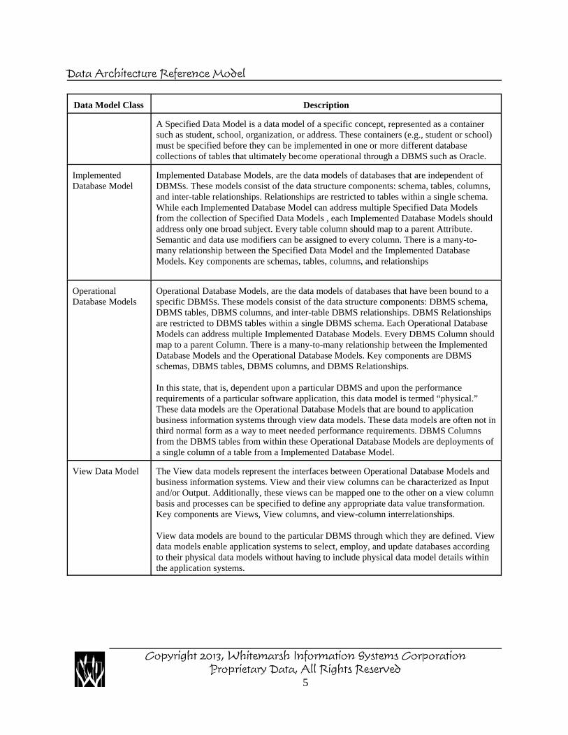
A Specified Data Model is a data model of a specific concept, represented as a containersuch as student, school, organization, or address. These containers (e.g., student or school)must be specified before they can be implemented in one or more different databasecollections of tables that ultimately become operational through a DBMS such as Oracle.
ImplementedDatabase Model
Implemented Database Models, are the data models of databases that are independent ofDBMSs. These models consist of the data structure components: schema, tables, columns,and inter-table relationships. Relationships are restricted to tables within a single schema.While each Implemented Database Model can address multiple Specified Data Modelsfrom the collection of Specified Data Models , each Implemented Database Models shouldaddress only one broad subject. Every table column should map to a parent Attribute.Semantic and data use modifiers can be assigned to every column. There is a many-to-many relationship between the Specified Data Model and the Implemented DatabaseModels. Key components are schemas, tables, columns, and relationships
OperationalDatabase Models
Operational Database Models, are the data models of databases that have been bound to aspecific DBMSs. These models consist of the data structure components: DBMS schema,DBMS tables, DBMS columns, and inter-table DBMS relationships. DBMS Relationshipsare restricted to DBMS tables within a single DBMS schema. Each Operational DatabaseModels can address multiple Implemented Database Models. Every DBMS Column shouldmap to a parent Column. There is a many-to-many relationship between the ImplementedDatabase Models and the Operational Database Models. Key components are DBMSschemas, DBMS tables, DBMS columns, and DBMS Relationships.
In this state, that is, dependent upon a particular DBMS and upon the performancerequirements of a particular software application, this data model is termed “physical.”These data models are the Operational Database Models that are bound to applicationbusiness information systems through view data models. These data models are often not inthird normal form as a way to meet needed performance requirements. DBMS Columnsfrom the DBMS tables from within these Operational Database Models are deployments ofa single column of a table from a Implemented Database Model.
View Data Model The View data models represent the interfaces between Operational Database Models andbusiness information systems. View and their view columns can be characterized as Inputand/or Output. Additionally, these views can be mapped one to the other on a view columnbasis and processes can be specified to define any appropriate data value transformation.Key components are Views, View columns, and view-column interrelationships.
View data models are bound to the particular DBMS through which they are defined. Viewdata models enable application systems to select, employ, and update databases accordingto their physical data models without having to include physical data model details withinthe application systems.
Copyright 2013, Whitemarsh Information Systems CorporationProprietary Data, All Rights Reserved
5
Data Architecture Reference Model
Data Model Class Description
XML InterfaceData Models
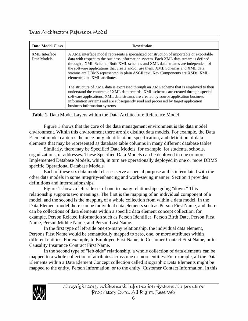
A XML interface model represents a specialized construction of importable or exportabledata with respect to the business information system. Each XML data stream is definedthrough a XML Schema. Both XML schemas and XML data streams are independent ofthe software applications that create and/or use them. XML Schemas and XML datastreams are DBMS represented in plain ASCII text. Key Components are XSDs, XMLelements, and XML attributes.
The structure of XML data is expressed through an XML schema that is employed to thenunderstand the contents of XML data records. XML schemas are created through specialsoftware applications. XML data streams are created by source application businessinformation systems and are subsequently read and processed by target applicationbusiness information systems.
Table 1. Data Model Layers within the Data Architecture Reference Model.
Figure 1 shows that the core of the data management environment is the data modelenvironment. Within this environment there are six distinct data models. For example, the DataElement model captures the once-only identification, specification, and definition of dataelements that may be represented as database table columns in many different database tables.
Similarly, there may be Specified Data Models, for example, for students, schools,organizations, or addresses. These Specified Data Models can be deployed in one or moreImplemented Database Models, which, in turn are operationally deployed in one or more DBMSspecific Operational Database Models.
Each of these six data model classes serve a special purpose and is interrelated with theother data models in some integrity-enhancing and work-saving manner. Section 4 providesdefinitions and interrelationships.
Figure 1 shows a left-side set of one-to-many relationships going "down." Thisrelationship supports two meanings. The first is the mapping of an individual component of amodel, and the second is the mapping of a whole collection from within a data model. In theData Element model there can be individual data elements such as Person First Name, and therecan be collections of data elements within a specific data element concept collection, forexample, Person Related Information such as Person Identifier, Person Birth Date, Person FirstName, Person Middle Name, and Person Last Name.
In the first type of left-side one-to-many relationship, the individual data element,Persons First Name would be semantically mapped to zero, one, or more attributes withindifferent entities. For example, to Employee First Name, to Customer Contact First Name, or toCausality Insurance Contract First Name.
In the second type of "left-side" relationship, a whole collection of data elements can bemapped to a whole collection of attributes across one or more entities. For example, all the DataElements within a Data Element Concept collection called Biographic Data Elements might bemapped to the entity, Person Information, or to the entity, Customer Contact Information. In this
Copyright 2013, Whitemarsh Information Systems CorporationProprietary Data, All Rights Reserved
6
Data Architecture Reference Model
case, the mapping of the data elements, Person Identifier, Person First Name, etc., is mapped to acorresponding set of attributes within one or more entities.
On the right-side of Figure 1, there is also a set of one-to-many relationships. This set,like the left-side one-to-many relationships has two meanings: individual component, and wholecollections. The meanings of the right-side one-to-many relationship are different from theleft-side one-to-many. The first type of right-side relationship, the mapping of an individualcomponent is not one-to-many, but one-to-one. Thus, an individual DBMS Column, for example,EmpFrstNam can be inherited from only one higher level component, for example, the singlecolumn, EmployeeFirstName.
The second type of right-side relationship, the mapping of collections can beone-to-many. That is, one collection can map to one set of columns within one table of a singleImplemented Database Model while another collection from the same Implemented DatabaseModel can be mapped to a different collection within a different Implemented Database Model.Hence, the collections can be seen as "from" one Implemented Database Model to zero, one, ormore Implemented Database Model.
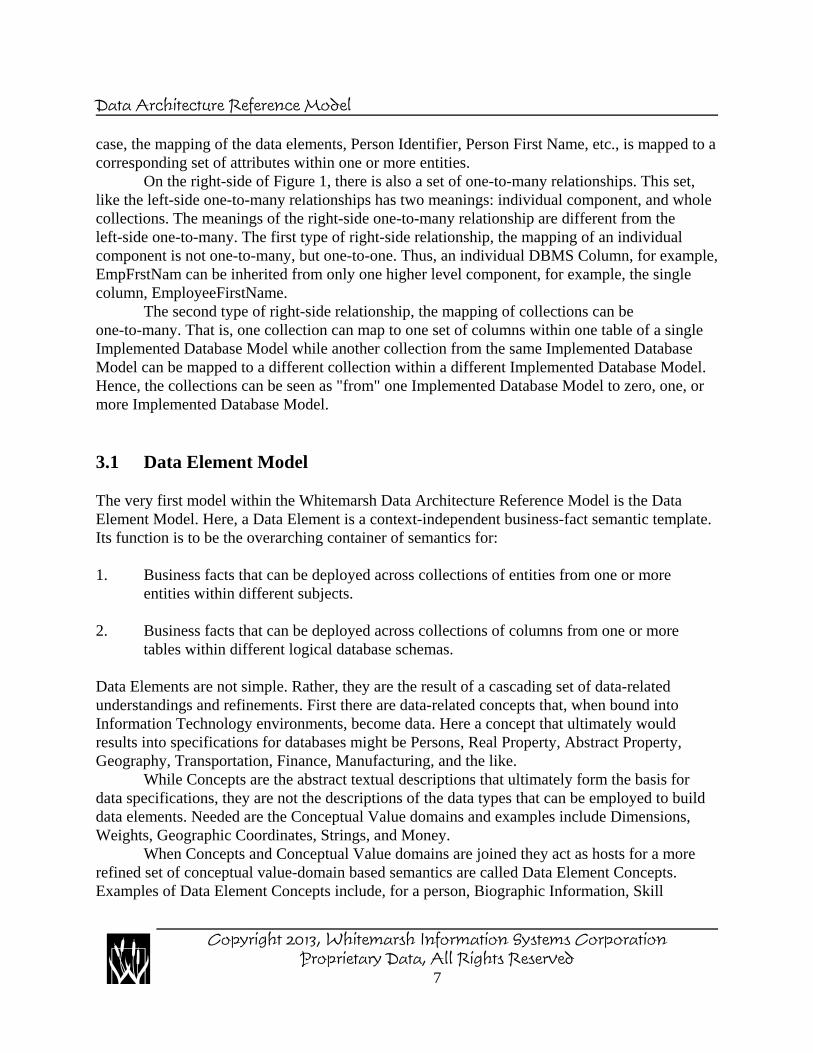
3.1 Data Element Model
The very first model within the Whitemarsh Data Architecture Reference Model is the DataElement Model. Here, a Data Element is a context-independent business-fact semantic template.Its function is to be the overarching container of semantics for:
1. Business facts that can be deployed across collections of entities from one or moreentities within different subjects.
2. Business facts that can be deployed across collections of columns from one or moretables within different logical database schemas.
Data Elements are not simple. Rather, they are the result of a cascading set of data-relatedunderstandings and refinements. First there are data-related concepts that, when bound intoInformation Technology environments, become data. Here a concept that ultimately wouldresults into specifications for databases might be Persons, Real Property, Abstract Property,Geography, Transportation, Finance, Manufacturing, and the like.
While Concepts are the abstract textual descriptions that ultimately form the basis fordata specifications, they are not the descriptions of the data types that can be employed to builddata elements. Needed are the Conceptual Value domains and examples include Dimensions,Weights, Geographic Coordinates, Strings, and Money.
When Concepts and Conceptual Value domains are joined they act as hosts for a morerefined set of conceptual value-domain based semantics are called Data Element Concepts.Examples of Data Element Concepts include, for a person, Biographic Information, Skill
Copyright 2013, Whitemarsh Information Systems CorporationProprietary Data, All Rights Reserved
7
Data Architecture Reference Model
Data Element
Value Domain
Conceptual Value
Domain
Conceptual Value Domain
Structure
Conceptual Value Domain Structure Type
Data Element Concept Structure
Data Element Concept
Structure TypeData Element
Concept
Value Domain Structure
Value Domain Structure Type
Value Domain Data
Type
Concept ConceptStructure
Concept Structure
Type
Data Element & Meta Category
Value
Meta Category Value
Data Element Classification
Structure
Data Element Classification
Structure Type
Data Element Classification
Data Element & Data Element Classification
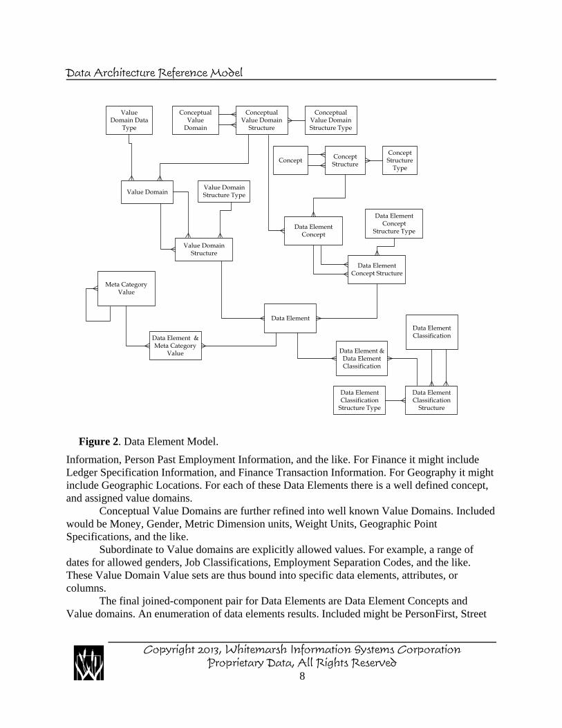
Figure 2. Data Element Model.
Information, Person Past Employment Information, and the like. For Finance it might includeLedger Specification Information, and Finance Transaction Information. For Geography it mightinclude Geographic Locations. For each of these Data Elements there is a well defined concept,and assigned value domains.
Conceptual Value Domains are further refined into well known Value Domains. Includedwould be Money, Gender, Metric Dimension units, Weight Units, Geographic PointSpecifications, and the like.
Subordinate to Value domains are explicitly allowed values. For example, a range ofdates for allowed genders, Job Classifications, Employment Separation Codes, and the like.These Value Domain Value sets are thus bound into specific data elements, attributes, orcolumns.
The final joined-component pair for Data Elements are Data Element Concepts andValue domains. An enumeration of data elements results. Included might be PersonFirst, Street
Copyright 2013, Whitemarsh Information Systems CorporationProprietary Data, All Rights Reserved
8
Data Architecture Reference Model
Name, House Number, Financial Instrument Identifier, Financial Instrument Amount, RealProduct Name, and the like.
Once the Data Elements are determined, they are ready to be employed as semantictemplates for use in Specified, Implemented, and Operational Data Models.
3.2 Specified Data Model
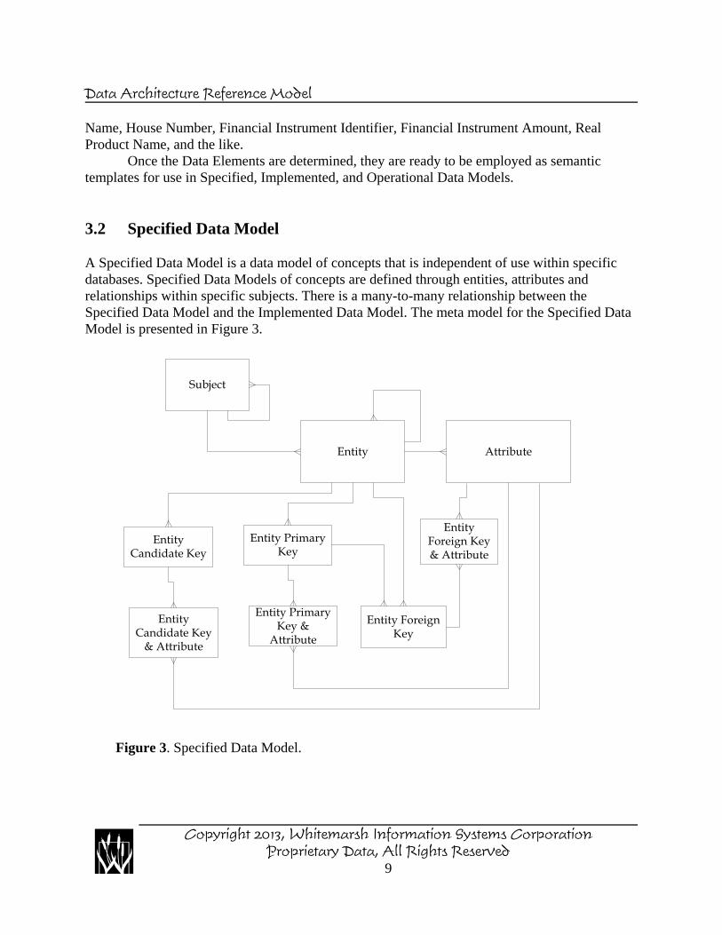
A Specified Data Model is a data model of concepts that is independent of use within specificdatabases. Specified Data Models of concepts are defined through entities, attributes andrelationships within specific subjects. There is a many-to-many relationship between theSpecified Data Model and the Implemented Data Model. The meta model for the Specified DataModel is presented in Figure 3.
AttributeEntity
Subject
Entity Primary Key
Entity Primary Key &
Attribute
Entity Foreign Key
Entity Foreign Key & Attribute
Entity Candidate Key
Entity Candidate Key
& Attribute
Figure 3. Specified Data Model.
Copyright 2013, Whitemarsh Information Systems CorporationProprietary Data, All Rights Reserved
9
Data Architecture Reference Model
In Specified Data Models, entities can have subtypes to any depth. An example might befor education which might have a common set of attributes for all classes of education, andsubtypes for each different education class such as high school, college, or trade school.
Attributes represent the deployment of data elements within entities. Because of this one-to-many relationship between data element and attribute, users can see which attributes employ adata element’s semantics regardless of the entity or subject.
Attributes can also be assigned various meaning modifier semantics and data usesemantics. This enables automatic name construction for attributes. Automatic definitions andabbreviations are also enabled because there is a persistent relationship between the assignedsemantic and the attribute. This too enables finding and reporting attributes regardless of entityand subject on the basis of either a semantic or data use modifier.
There can also be relationships among the entities within one subject, and there can berelationships between entities across subjects. If this were just a data model in a conceptual form,there could not be relationships across different subject-based data models. Each conceptual datamodel would be a stove-pipe that could only be transformed into a logical stove pipe data modeland thereafter into a physical stove pipe data model.
Again, Specified Data Models are not conceptual forms of a data model. Rather, they arewell-developed data models in their own right. Each entity within a Specified Data Model shouldbe in third normal form. Specified Data Models are persistent. Their form remains as defined. Itsstructures, that is, the data models of the concepts, are available as templates for the constructionof one or more Implemented Data Models.
3.3 Implemented Data Model
Implemented Data Models are models of databases that are independent of any particular DBMSsuch as Oracle or DB2. In the Whitemarsh Metabase System, Implemented Data Models can beexported to SQL DDL.
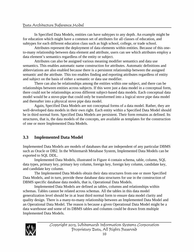
Implemented Data Models, illustrated in Figure 4 contain schema, table, column, SQLdata types, primary key, primary key column, foreign key, foreign key column, candidate key,and candidate key column.
The Implemented Data Models obtain their data structures from one or more SpecifiedData Models, and in turn, provide these database data structures for use in the construction ofDBMS specific database data models, that is, Operational Data Models.
Implemented Data Models are defined as tables, columns and relationships withinschemas. Tables cannot be related across schemas. All the tables in this data modelgeneralization level should be in at least third normal form to ensure data model clarity andquality design. There is a many-to-many relationship between an Implemented Data Model andan Operational Data Model. The reason is because a given Operational Data Model might be adata warehouse and some of its DBMS tables and columns could be drawn from multipleImplemented Data Models.
Copyright 2013, Whitemarsh Information Systems CorporationProprietary Data, All Rights Reserved
10
Data Architecture Reference Model
There can be relationships among the tables within one schema as well as data types,assigned value domains and other appropriate metadata for complete data models. There can alsobe assigned semantic modifiers, data use modifiers, and value domains assigned in theImplemented Data Model. Thus, as with the Specified Data Model there can be automatic name,definition, and abbreviation construction. Because the Implemented Data Model comes from ametadata management system database, any semantic assignment conflicts between the Specifiedand Implemented Data Models are immediately discovered and prevented. If the semantics
Table Primary Key
Column
Table
Table Primary Key & Column
Table Foreign Key
Table Foreign Key & Column
Schema
SQL Data Type
TableCandidate Key
TableCandidate Key
& Column
Figure 4. Implemented Data Model.
Copyright 2013, Whitemarsh Information Systems CorporationProprietary Data, All Rights Reserved
11
Data Architecture Reference Model
already assigned to attributes of entities within the Specified Data Model are sufficient, these areautomatically inherited by columns of tables in the Implemented Data Model.
Each table may be constructed through the deployment of a collection of attributes from asingle Specified Data Model entity, or collections of attributes from multiple Specified DataModel entities within one or more subjects. An entity or sub-collection of attributes from oneentity can be used to form different data structures in multiple tables. The relationship betweenthe Specified Data Model and the Implemented Data Model is thus, many-to-many, as it exists inreal-world data modeling environments.
Tables in the Implemented Data Model can be subtyped. Columns can also be complex tosupport nested structures of arbitrary depth. The data types assigned to an Implemented DataModel are those allowed by the ANSI SQL standard.
Finally, because the Implemented Data Model is built from a foundation of the datamodels of concepts from the Specified Data Model, a complete cross reference between the twoclasses of models is easily reported.
3.4 Operational Data Model
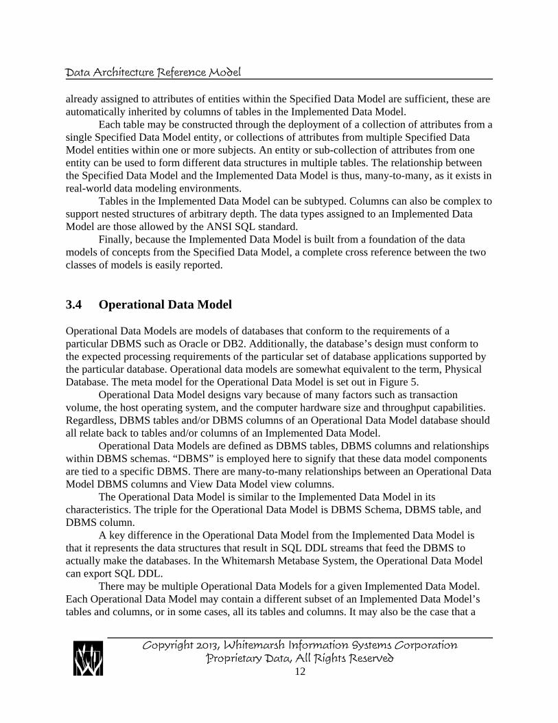
Operational Data Models are models of databases that conform to the requirements of aparticular DBMS such as Oracle or DB2. Additionally, the database’s design must conform tothe expected processing requirements of the particular set of database applications supported bythe particular database. Operational data models are somewhat equivalent to the term, PhysicalDatabase. The meta model for the Operational Data Model is set out in Figure 5.
Operational Data Model designs vary because of many factors such as transactionvolume, the host operating system, and the computer hardware size and throughput capabilities.Regardless, DBMS tables and/or DBMS columns of an Operational Data Model database shouldall relate back to tables and/or columns of an Implemented Data Model.
Operational Data Models are defined as DBMS tables, DBMS columns and relationshipswithin DBMS schemas. “DBMS” is employed here to signify that these data model componentsare tied to a specific DBMS. There are many-to-many relationships between an Operational DataModel DBMS columns and View Data Model view columns.
The Operational Data Model is similar to the Implemented Data Model in itscharacteristics. The triple for the Operational Data Model is DBMS Schema, DBMS table, andDBMS column.
A key difference in the Operational Data Model from the Implemented Data Model isthat it represents the data structures that result in SQL DDL streams that feed the DBMS toactually make the databases. In the Whitemarsh Metabase System, the Operational Data Modelcan export SQL DDL.
There may be multiple Operational Data Models for a given Implemented Data Model.Each Operational Data Model may contain a different subset of an Implemented Data Model’stables and columns, or in some cases, all its tables and columns. It may also be the case that a
Copyright 2013, Whitemarsh Information Systems CorporationProprietary Data, All Rights Reserved
12
Data Architecture Reference Model
complete set of a table’s columns are transformed into differently named columns. For example,there might have been an Implemented Data Model table for telephone numbers that, in theOperational Data Model, are transformed into TelephoneNumber-1 through TelephoneNumber-5. This is a kind of Operational Data Model denormalization may be created to improveperformance.
There may also have been multiple Implemented Data Models for a given OperationalData Model. This commonly occurs in data warehouse data model designs where the OperationalData Model for the data warehouse is sourced from multiple Implemented Data Models.
Database
DBMS DBMS Schema
DBMS Column
DBMS Table
DBMS Data Type
DBMS Table Primary Key
DBMS Table Primary Key & DBMS Column
DBMS Table Foreign Key &
Column
DBMS Table Foreign Key
Database Architecture Class
DBMS Table CandidateKey & DBMS Column
DBMS Table Candidate Key
DBMS Table Secondary Key
DBMS Table Secondary Key & DBMS Column
Figure 5. Operational Data Model.
Copyright 2013, Whitemarsh Information Systems CorporationProprietary Data, All Rights Reserved
13
Data Architecture Reference Model
The Operational Data Model can contain subtyped DBMS tables, and substructures inDBMS Columns. It can also have an assigned value domain and the data types reflect that of thecontaining DBMS.
3.5 View Data Model
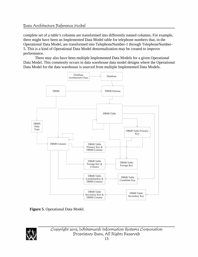
View Data Models are the Business Information System and Operational Data Modelintersection mechanisms. View data models, depicted in Figure 6, contain the followingcomponents: View, View Column, View Column & Compound Data Element, View Column &Derived Data Element, View Column & DBMS Column, View Column Structure, View ColumnStructure Process, and View Column Structure Type
View
View Column
View Column & Compound Data
Element
View Column & Derived Data
Element
View Column & DBMS Column
View Column Structure
View Column Structure TypeView Column
Structure Process
Figure 6. View Data Model.
Copyright 2013, Whitemarsh Information Systems CorporationProprietary Data, All Rights Reserved
14
Data Architecture Reference Model
View data models consist of views and view columns. They are also related to thebusiness information systems that are the sources or targets of the database data. Views arespecifically tied to specific DBMSs and view columns from a source view may be mapped to theview columns of a target view. Finally, view columns may be computed or derived.
View data models give applications a flat “record set” for processing. Included in viewscan be rename clauses and on-the-fly calculations. View columns not only map to DBMScolumns but also, as appropriate, to compound data elements and derived data elements.
3.6 XML Schema Data Model
A XML interface model represents a specialized construction of importable or exportable datawith respect to the business information system. Each XML data stream is defined through aXML Schema. Both XML schemas and XML data streams are independent of the softwareapplications that create and/or use them. XML Schemas and XML data streams are DBMSrepresented in plain ASCII text. Key Components are XSDs, XML elements, and XMLattributes.
The structure of XML data is expressed through an XML schema that is employed tothen understand the contents of XML data records. XML schemas are created through specialsoftware applications. XML data streams are created by source application business informationsystems and are subsequently read and processed by target application business informationsystems.
4.0 Deployment of Data Architecture Models within Business InformationSystem Development
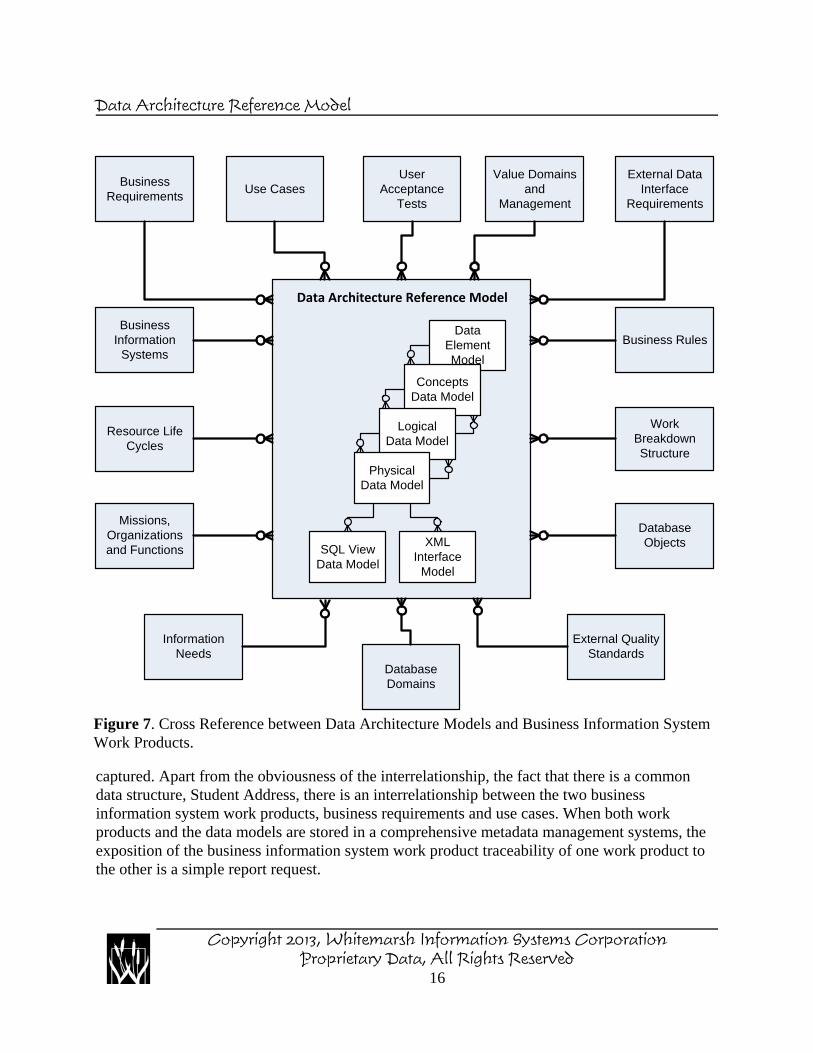
We are all familiar with the collection of work products that are identified, engineered, created,evolved and maintained during the life cycle of business information systems. While there can bean endless array of names for some of these work products, they generally fall into the workproduct categories that are listed in column one of Table 2. A depiction of the interrelationshipsof the data models and of the work products is presented in Figure 7. Table 2 also shows thecross reference between the Data Architecture reference model data models and the typical workproducts of a business information system effort.
Business Information System Work Products, for example, Business Requirements,shown in Figure 7 can have a one-to-many relationship between one or more different businessinformation system work products and zero, one or more of the data models. When two or morebusiness information system work products are interrelated with one or more of the data models,there may exist relationship between those two business information system work productsthrough artifacts contained in the data models. For example, there is a business requirement tocapture student addresses. Additionally, there is a use case through which a student's address is
Copyright 2013, Whitemarsh Information Systems CorporationProprietary Data, All Rights Reserved
15
Data Architecture Reference Model
captured. Apart from the obviousness of the interrelationship, the fact that there is a commondata structure, Student Address, there is an interrelationship between the two businessinformation system work products, business requirements and use cases. When both workproducts and the data models are stored in a comprehensive metadata management systems, theexposition of the business information system work product traceability of one work product tothe other is a simple report request.
Data Element Model
Concepts Data Model
Logical Data Model
Physical Data Model
SQL View Data Model
XML Interface
Model
Data Architecture Reference Model
Business Requirements
External Quality Standards
Database Objects
Work Breakdown Structure
Business Rules
External Data Interface
Requirements
Resource Life Cycles
Business Information
Systems
Value Domains and
Management
User Acceptance
TestsUse Cases
Missions, Organizations and Functions
Information Needs
Database Domains
Figure 7. Cross Reference between Data Architecture Models and Business Information SystemWork Products.
Copyright 2013, Whitemarsh Information Systems CorporationProprietary Data, All Rights Reserved
16
Data Architecture Reference Model
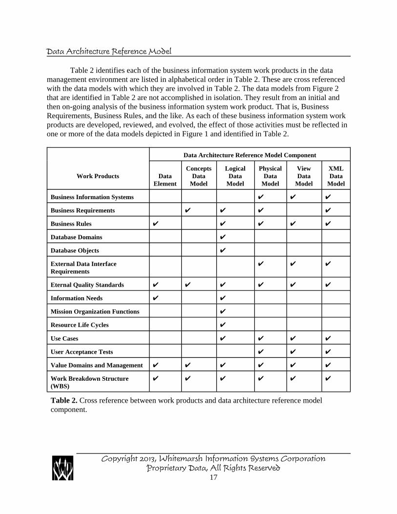
Table 2 identifies each of the business information system work products in the datamanagement environment are listed in alphabetical order in Table 2. These are cross referencedwith the data models with which they are involved in Table 2. The data models from Figure 2that are identified in Table 2 are not accomplished in isolation. They result from an initial andthen on-going analysis of the business information system work product. That is, BusinessRequirements, Business Rules, and the like. As each of these business information system workproducts are developed, reviewed, and evolved, the effect of those activities must be reflected inone or more of the data models depicted in Figure 1 and identified in Table 2.
Work Products
Data Architecture Reference Model Component
DataElement
ConceptsData
Model
LogicalData
Model
PhysicalData
Model
ViewData
Model
XMLData
Model
Business Information Systems U U U
Business Requirements U U U U
Business Rules U U U U U
Database Domains U
Database Objects U
External Data InterfaceRequirements
U U U
Eternal Quality Standards U U U U U U
Information Needs U U
Mission Organization Functions U
Resource Life Cycles U
Use Cases U U U U
User Acceptance Tests U U U
Value Domains and Management U U U U U U
Work Breakdown Structure(WBS)
U U U U U U
Table 2. Cross reference between work products and data architecture reference modelcomponent.
Copyright 2013, Whitemarsh Information Systems CorporationProprietary Data, All Rights Reserved
17

Data Architecture Reference Model
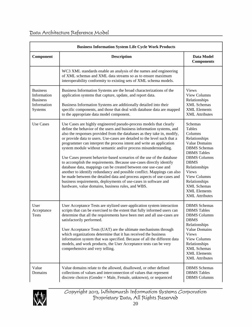
Each of the business information system work products are identified and described in Table 3.The last column of Table 3 enumerates the key data model artifacts that are involved with thework product. The data models that contain these artifacts are identified in Table 1.
This document does not address how to create each of these business information systemwork products because the creation process is more than adequately addressed within otherWhitemarsh books, courses, seminars, and methodology documents. Rather, the focus of thisdocument presumes is to assess the necessary and sufficient interaction among all the businessinformation system work products.
Business Information System Life Cycle Work Products
Component Description Data ModelComponents
BusinessRequirements
Business Requirements are the identification, specification, anddefinition of the components that must exist in the ultimate solutiondelivered by the contractor.
Business Requirements form the foundation upon which all componentsof are engineered, implemented, and maintained. Business requirementswill evolve over time. Thus, it is important to be able to track the initialand evolved requirements. It is unrealistic to initially have allrequirements because new and/or revised requirements are discoveredall during the project’s architecture, engineering, and implementation.
Subjects,EntitiesAttributesData ElementsDatabase DomainsDatabase Objects
BusinessRules
Business Rules are assertions of truth-states in the database. Eachbusiness rule includes the identification, name, description, and exactspecification of data-based rules that must either be true or that, after theexecution of an information system process, results in a state of truth.
There are two classes of Business Rules: data and process. Almostinvariably, business rules depend on existing data, reference or controldata, or data that is determined as a consequence of a process’sexecution. Almost all business rules are mappable to data, whetherpersistent or temporary.
Business rules are almost always discovered during design sessions, anduse-case walkthroughs. As business rules are discovered, the variousdata models need to be concurrently examined to determine whether thedatabase can support the rules. Since every business rule has a processcomponent, a key component of each rule is the specification of theprocess and a determination of where that rule is bound. That is, boundinto the data model component (e.g., Data Element, or DBMS column),a low-level application component, a mid-level application process, orin the user presentation layer.
Because of this multiplicity of possible bindings, business rules need tobe centrally defined and managed, but bound only into the data model
SchemaTablesColumnsDBMS SchemaDBMS TablesDBMS ColumnsValue Domains
Copyright 2013, Whitemarsh Information Systems CorporationProprietary Data, All Rights Reserved
18

Data Architecture Reference Model
Business Information System Life Cycle Work Products
Component Description Data ModelComponents
or business information system work product within which it isaccomplished.
WorkBreakdownStructure(WBS)
Work Breakdown Structures are hierarchical representations of twoclasses of effort: What, and How. The “what” type of WBS contains anaction phrase and a noun phrase that together describe what is to bedone, and the name of the work product creation or evolution.
The second class of WBS, the “how WBSs” are tuned to deliverablesbut to the actual techniques employed to accomplish the data model orbusiness information system work product.
Both the “What” WBS and the “How” WBSs need to be interlinked.Well developed metadata management systems include completeproject management so that work plans and progress against work planscan be directly tied to and integrated with accomplishments.
Subjects,EntitiesAttributesData ElementsDatabase DomainsDatabase ObjectsSchemaTablesColumnsDBMS SchemaDBMS TablesDBMS Columns
External datainterface DataRequirements
External data interface Requirements are the specifications of aninterface between an internal database data structure and some externaldata source. Each interface essentially consists of a fully defined datamodel that defines every field in the interface to the extent that asoftware module can be created to read the records represented by theinterface and take appropriate action against the database. Such actionscan be to insert, delete, or modify database records.
DBMS SchemasDBMS TablesDBMS ColumnsDBMSRelationshipsValue DomainsViewsView ColumnsRelationshipsXML SchemasXML ElementsXML Attributes
ExternalQualityStandards
External Quality Standards are de jure and de facto standards throughwhich data management products and/or processes can be judged.
The ISO Standard 11179 enables assessment of the adequacy andcompleteness of the metadata associated with data elements. Included inthis class of assessment are Concepts, Conceptual Value Domains, DataElement Concepts, Value Domains including mapping amongequivalent values, Data Element Classifications, and AdministrativeInformation (for Stewardship).
The ISO/ANSI SQL standard enables the assessment of SQL datastructures and languages employed in database designs and applicationprogram access.
SchemasTablesColumnsRelationshipsViewsView ColumnsRelationshipsXML SchemasXML ElementsXML Attributes
Copyright 2013, Whitemarsh Information Systems CorporationProprietary Data, All Rights Reserved
19
Data Architecture Reference Model
Business Information System Life Cycle Work Products
Component Description Data ModelComponents
WC3 XML standards enable an analysis of the names and engineeringof XML schemas and XML data streams so as to ensure maximuminteroperability conformity to existing sets of XML schema models.
BusinessInformationBusinessInformationSystems
Business Information Systems are the broad characterizations of theapplication systems that capture, update, and report data.
Business Information Systems are additionally detailed into theirspecific components, and those that deal with database data are mappedto the appropriate data model component.
ViewsView ColumnsRelationshipsXML SchemasXML ElementsXML Attributes
Use Cases Use Cases are highly engineered pseudo-process models that clearlydefine the behavior of the users and business information systems, andalso the responses provided from the databases as they take in, modify,or provide data to users. Use-cases are detailed to the level such that aprogrammer can interpret the process intent and write an applicationsystem module without semantic and/or process misunderstanding.
Use Cases present behavior-based scenarios of the use of the databaseto accomplish the requirements. Because use-cases directly identifydatabase data, mappings can be created between one use-case andanother to identify redundancy and possible conflict. Mappings can alsobe made between the detailed data and process aspects of use-cases andbusiness requirements, deployments of use-cases in software andhardware, value domains, business rules, and WBS.
SchemasTablesColumnsRelationshipsValue DomainsDBMS SchemasDBMS TablesDBMS ColumnsDBMSRelationshipsViewsView ColumnsRelationshipsXML SchemasXML ElementsXML Attributes
UserAcceptanceTests
User Acceptance Tests are stylized user-application system interactionscripts that can be exercised to the extent that fully informed users candetermine that all the requirements have been met and all use-cases aresatisfactorily performed.
User Acceptance Tests (UAT) are the ultimate mechanisms throughwhich organizations determine that it has received the businessinformation system that was specified. Because of all the different datamodels, and work products, the User Acceptance tests can be verycomprehensive and very telling.
DBMS SchemasDBMS TablesDBMS ColumnsDBMSRelationshipsValue DomainsViewsView ColumnsRelationshipsXML SchemasXML ElementsXML Attributes
ValueDomains
Value domains relate to the allowed, disallowed, or other definedcollections of values and interconnection of values that representdiscrete choices (Gender = Male, Female, unknown), or sequenced
DBMS SchemasDBMS TablesDBMS Columns
Copyright 2013, Whitemarsh Information Systems CorporationProprietary Data, All Rights Reserved
20
Data Architecture Reference Model
Business Information System Life Cycle Work Products
Component Description Data ModelComponents
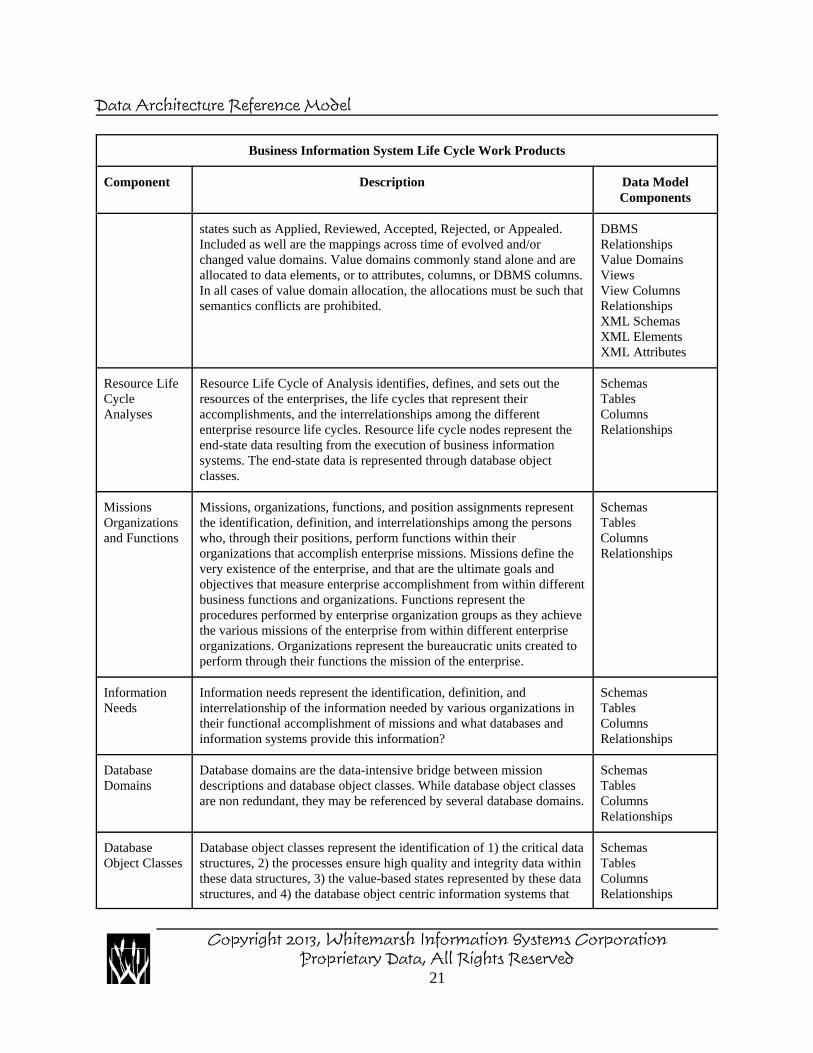
states such as Applied, Reviewed, Accepted, Rejected, or Appealed.Included as well are the mappings across time of evolved and/orchanged value domains. Value domains commonly stand alone and areallocated to data elements, or to attributes, columns, or DBMS columns.In all cases of value domain allocation, the allocations must be such thatsemantics conflicts are prohibited.
DBMSRelationshipsValue DomainsViewsView ColumnsRelationshipsXML SchemasXML ElementsXML Attributes
Resource LifeCycleAnalyses
Resource Life Cycle of Analysis identifies, defines, and sets out theresources of the enterprises, the life cycles that represent theiraccomplishments, and the interrelationships among the differententerprise resource life cycles. Resource life cycle nodes represent theend-state data resulting from the execution of business informationsystems. The end-state data is represented through database objectclasses.
SchemasTablesColumnsRelationships
MissionsOrganizationsand Functions
Missions, organizations, functions, and position assignments representthe identification, definition, and interrelationships among the personswho, through their positions, perform functions within theirorganizations that accomplish enterprise missions. Missions define thevery existence of the enterprise, and that are the ultimate goals andobjectives that measure enterprise accomplishment from within differentbusiness functions and organizations. Functions represent theprocedures performed by enterprise organization groups as they achievethe various missions of the enterprise from within different enterpriseorganizations. Organizations represent the bureaucratic units created toperform through their functions the mission of the enterprise.
SchemasTablesColumnsRelationships
InformationNeeds
Information needs represent the identification, definition, andinterrelationship of the information needed by various organizations intheir functional accomplishment of missions and what databases andinformation systems provide this information?
SchemasTablesColumnsRelationships
DatabaseDomains
Database domains are the data-intensive bridge between missiondescriptions and database object classes. While database object classesare non redundant, they may be referenced by several database domains.
SchemasTablesColumnsRelationships
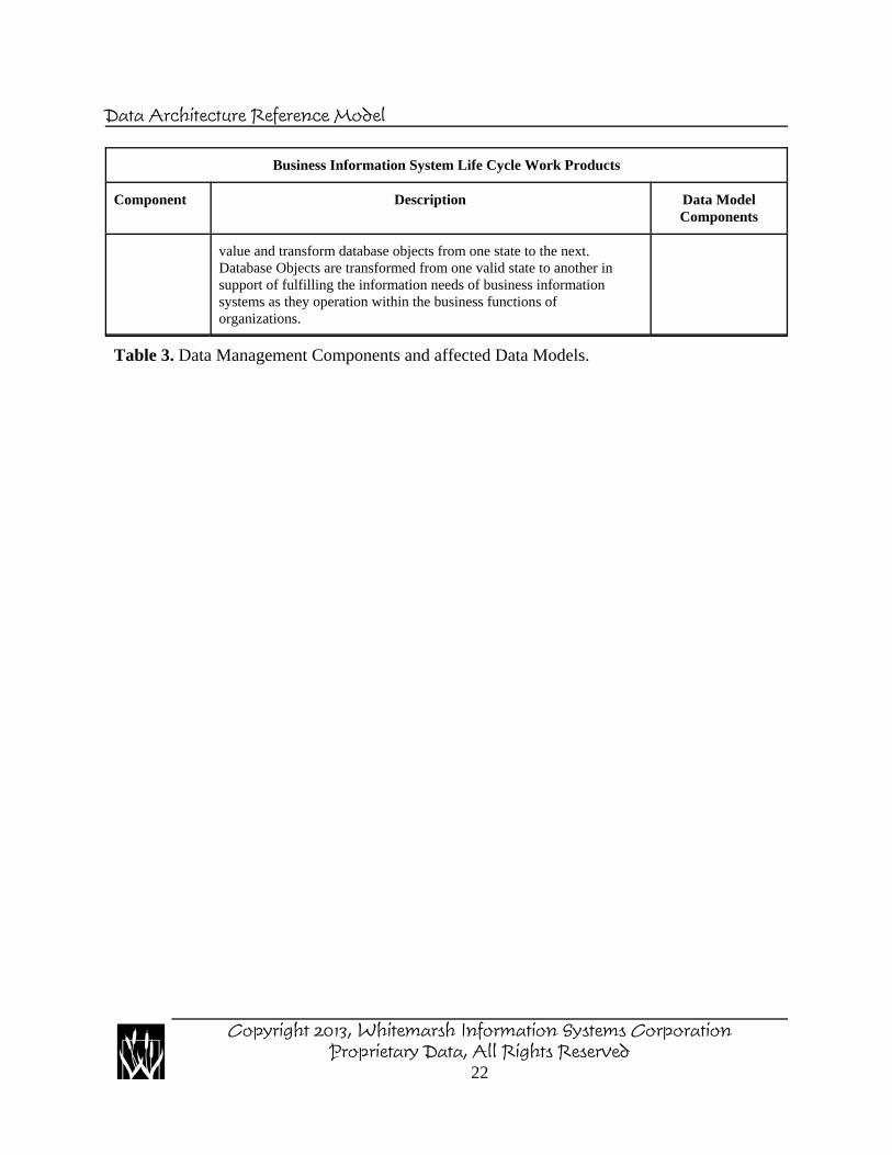
DatabaseObject Classes
Database object classes represent the identification of 1) the critical datastructures, 2) the processes ensure high quality and integrity data withinthese data structures, 3) the value-based states represented by these datastructures, and 4) the database object centric information systems that
SchemasTablesColumnsRelationships
Copyright 2013, Whitemarsh Information Systems CorporationProprietary Data, All Rights Reserved
21
Data Architecture Reference Model
Business Information System Life Cycle Work Products
Component Description Data ModelComponents
value and transform database objects from one state to the next.Database Objects are transformed from one valid state to another insupport of fulfilling the information needs of business informationsystems as they operation within the business functions oforganizations.
Table 3. Data Management Components and affected Data Models.
Copyright 2013, Whitemarsh Information Systems CorporationProprietary Data, All Rights Reserved
22