darwin-genie instrument definition study - summary report
TRANSCRIPT
Darwin-GENIEInstrument
DefinitionStudy
Doc. No: GDS-SR-01 Issue: 1 Date: 2 February 2005 File: SR_GENIE_01.doc Pages: 21
Title:
Summary Report
With contributions of: EADS Astrium GmbH
TNO-TPD
TU-Wien
Observatory Leiden
MPIA Heidelberg
Contract No.: ESTEC/Contract No. 17657/03/NL/HB
Darwin-GENIE Instrument Definition Study
Prepared by: R. Flatscher / EADS Astrium Dep. AED41 Date: 2 February 2005
Checked by: K. Ergenzinger O. Wallner Date: 31 January 2005
Project Management: R. Flatscher
Distribution: see Distribution List
Copying of this document, and giving it to others and the use or communication of the contents there-of, are forbidden without express
authority. Offenders are liable to the payment of damages. All rights are reserved in the event of the grant of a patent or the registration of a
utility model or design.

Distribution List
Darwin-GENIEInstrument
DefinitionStudy
Doc. No: GDS-SR-01 Issue: 1 Date: 2 February 2005 File: SR_GENIE_01.doc Page A-I
Quantity Name Company / Department
20 P. Gondoin ESTEC
1 E. Boslooper TNO-TPD
1 Prof. W. Leeb TU-Wien
1 Prof. A. Quirrenbach Observatory Leiden
1 U. Graser MPIA Heidelberg
1 R. Flatscher EADS Astrium GmbH
Change Record
Darwin-GENIEInstrument
DefinitionStudy
Doc. No: GDS-SR-01 Issue: 1 Date: 2 February 2005 File: SR_GENIE_01.doc Page B-I
Issue Date Sheets Description of Change Release
1
2 February 2005
all
initial issue
1

Register of Changes
Darwin-GENIEInstrument
DefinitionStudy
Doc. No: GDS-SR-01 Issue: 1 Date: 2 February 2005 File: SR_GENIE_01.doc Page C-I
Issue 1 2 3 4 5 6 7 8 Issue 1 2 3 4 5 6 7 8
Dat
e
Dat
e
Sheet Sheet
Darwin-GENIE Instrument
Definition Study
Doc. No: GDS-SR-01 Issue: 1 Date: 2 February 2005 File: SR_GENIE_01.doc Page i
Table of Contents
1 SCIENTIFIC AND PROGRAMMATIC BACKGROUND 1
2 PROJECT TEAM AND RESPONSIBILITIES 2
3 GENIE OBJECTIVES AND TECHNICAL REQUIREMENTS 3
4 GENIE CONCEPTS 4
4.1 Bracewell Concept as Baseline 4
4.2 Optional Split Pupil Nuller (Internal Phase Chopping) 6
4.3 Conceptual Layout of GENIE and Proposed Implementation 9
5 GENIE KEY COMPONENTS 15
5.1 Detectors 15
5.2 Beam Splitters 16
5.3 Wavefront Filter 16
5.4 Phase Shifter 16
5.5 Main Delay Line and Related Air Mass 17
5.6 Control Loops 17
6 PERFORMANCE ESTIMATE 18
7 CONCLUSIONS AND RECOMMENDATION 21

Darwin-GENIE Instrument
Definition Study
Doc. No: GDS-SR-01 Issue: 1 Date: 2 February 2005 File: SR_GENIE_01.doc Page ii

Darwin-GENIE Instrument
Definition Study
Doc. No: GDS-SR-01 Issue: 1 Date: 2 February 2005 File: SR_GENIE_01.doc Page 1
1 SCIENTIFIC AND PROGRAMMATIC BACKGROUND
Darwin-GENIE (Ground-based European Nulling Interferometer Experiment) is a technology demonstrator conceived to test on ground at system level some of the key technologies required to accomplish the Darwin InfraRed Space Interferometer mission. It is also designed to provide the European astronomers with a scientifically useful instrument exploiting the nulling interferometry technique.
Darwin is one of the most challenging space projects ever considered by the European Space Agency (ESA). It aims to detect Earth-like planets around nearby stars and to characterise their atmospheres. The Darwin mission uses an optical nulling interferometry technique, which coherently combines the light beams collected by telescopes on board of independent spacecrafts. The technological challenge is twofold. Firstly, the deployment and remote operations of a flotilla of spacecrafts have to be developed and demonstrated with very high position accuracy. Secondly, the nulling combination of the wavefront signals from independent telescopes has to be proven with the efficiency necessary to retrieve a dim planet signal from the overwhelming brightness of its parent star. Darwin-GENIE aims to demonstrate and test the principle of nulling interferometry using ground-based telescopes and Darwin-representative technologies.
A dedicated laboratory nulling breadboard, with star-planet simulators, was recently demonstrated by Astrium Germany within the frame of the ESA TRP programme. The emphasis in the design of this breadboard has been put on the demonstration of deep nulling in a narrow, near IR band rather than on a more representative system, operating in the mid-IR atmospheric spectral bands where specific detector, optical and cryogenics technology bring additional cost and complexity. Based on the performance of these laboratory breadboards, the next step is to adapt their design to mid-IR operations and to test them on astronomical targets using a ground based interferometer. This task will be achieved by developing a nulling breadboard to test the Darwin nulling technique using the existing infrastructure of the Very Large Telescope Interferometer (VLTI) at the European Southern Observatory (ESO). The prioritised objectives of the ground-based nulling demonstrator, Darwin-GENIE, are as follows.
! to gain experience on the design, manufacture and operation of a nulling interferometer using Darwin representative concepts and technology
! to prepare the Darwin science programme through a systematic survey of Darwin candidate targets
! to perform Darwin related science, as achievable from ground, including spectroscopy of exo-zodiacal dust clouds around Darwin targets and low-mass companions around nearby stars
! to provide the astronomical community with a scientifically useful instrument which will promote the use of the nulling interferometry technique in space.

Darwin-GENIE Instrument
Definition Study
Doc. No: GDS-SR-01 Issue: 1 Date: 2 February 2005 File: SR_GENIE_01.doc Page 2
2 PROJECT TEAM AND RESPONSIBILITIES
EADS Astrium Germany has been awarded one of the two instrument definition studies contracted by ESA. The study team was composed of the subcontractors TNO, Technische Universität Wien, MPIA Heidelberg, and Observatory Leiden. Astrium, TNO, and TU-Wien were already involved in the nulling breadboard activity (Multi Aperture Imaging Interferometer) which could be finished in early 2003 with great success. The elegant OPD stabilisation used there was brought in to the GENIE definition study as one key element.
In parallel Astrium has been awarded with the "Single Mode Fibres for Darwin" activity aiming at the design, manufacturing, and testing of single-mode fibres. This special fibre is used as wavefront filter in any interferometric instrument and forms the second key element for the GENIE device. Astrium recently demonstrated (September 2004) the feasibility of single mode fibres based on drawn chalcogenide glasses and extruded poly-crystalline silver halide fibres. The first technology can be immediately used in the GENIE wavelength range whereas the latter technology is tailored to the full Darwin wavelength range. This successful hardware project was led by Astrium with ART-Photonics, and TU-Wien as subcontractors. The single mode demonstration at a wavelength of 10.6 µm was a world premiere. The mode suppression capability of the wavefront filter has been confirmed by using a Mach Zehnder test interferometer.
The responsibilities of the team members within the GENIE instrument definition study were as follows
! EADS Astrium Germany concept definition and trade-off, key components and specifications, interfaces and implementation plan, performance and error budgets on top level, and functional requirements
! TNO-TPD preliminary and consolidated design error budget on component level
! Technische Universität Wien performance simulation and error budgets on subsystem level
! MPIA Heidelberg support concerning VLTI interfaces and detector technology experience of mid-infrared operational MIDI instrument
! Observatory Leiden support concerning targets and scenarios consultancy related to phase modulation
The basic funding was provided by ESA but substantial internal funding has been added by Astrium and TNO to increase the study's output and to investigate in detail all promising concepts.
Darwin-GENIE Instrument
Definition Study
Doc. No: GDS-SR-01 Issue: 1 Date: 2 February 2005 File: SR_GENIE_01.doc Page 3
3 GENIE OBJECTIVES AND TECHNICAL REQUIREMENTS
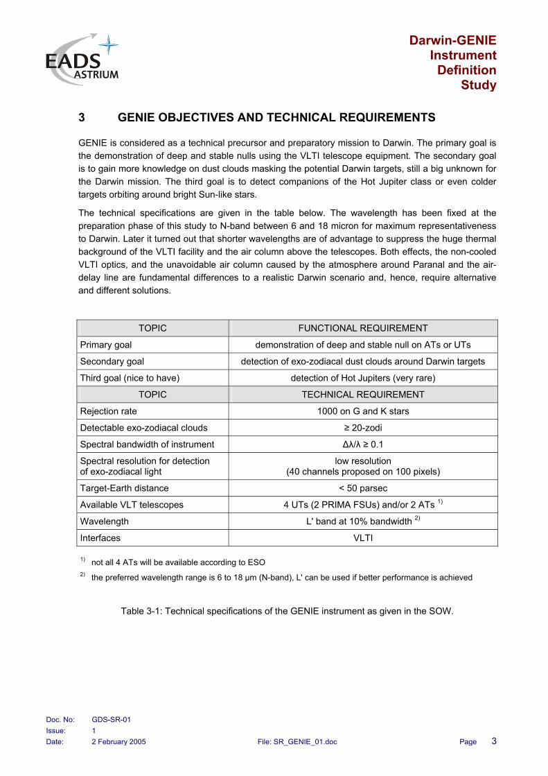
GENIE is considered as a technical precursor and preparatory mission to Darwin. The primary goal is the demonstration of deep and stable nulls using the VLTI telescope equipment. The secondary goal is to gain more knowledge on dust clouds masking the potential Darwin targets, still a big unknown for the Darwin mission. The third goal is to detect companions of the Hot Jupiter class or even colder targets orbiting around bright Sun-like stars.
The technical specifications are given in the table below. The wavelength has been fixed at the preparation phase of this study to N-band between 6 and 18 micron for maximum representativeness to Darwin. Later it turned out that shorter wavelengths are of advantage to suppress the huge thermal background of the VLTI facility and the air column above the telescopes. Both effects, the non-cooled VLTI optics, and the unavoidable air column caused by the atmosphere around Paranal and the air-delay line are fundamental differences to a realistic Darwin scenario and, hence, require alternative and different solutions.
TOPIC FUNCTIONAL REQUIREMENT
Primary goal demonstration of deep and stable null on ATs or UTs
Secondary goal detection of exo-zodiacal dust clouds around Darwin targets
Third goal (nice to have) detection of Hot Jupiters (very rare)
TOPIC TECHNICAL REQUIREMENT
Rejection rate 1000 on G and K stars
Detectable exo-zodiacal clouds ≥ 20-zodi
Spectral bandwidth of instrument ∆λ/λ ≥ 0.1
Spectral resolution for detection of exo-zodiacal light
low resolution (40 channels proposed on 100 pixels)
Target-Earth distance < 50 parsec
Available VLT telescopes 4 UTs (2 PRIMA FSUs) and/or 2 ATs 1)
Wavelength L' band at 10% bandwidth 2)
Interfaces VLTI
1) not all 4 ATs will be available according to ESO 2) the preferred wavelength range is 6 to 18 µm (N-band), L' can be used if better performance is achieved
Table 3-1: Technical specifications of the GENIE instrument as given in the SOW.

Darwin-GENIE Instrument
Definition Study
Doc. No: GDS-SR-01 Issue: 1 Date: 2 February 2005 File: SR_GENIE_01.doc Page 4
4 GENIE CONCEPTS
Several different instrument concepts have been studied and traded including internal and inherent phase modulation and using in-band as well as out-band fringe tracking. Internal metrology is partly required to keep stable the optical paths between fringe tracker and nulling core.
Two special concepts have been selected for further investigation:
! standard Bracewell configuration as baseline using two UT or AT telescopes
! optional split pupil nuller as extension to the standard Bracewell for exo-zodical dust detection
The baseline concept uses virtual chopping to subtract the background radiation still masking the scientific signal even in L' band.
The split pupil nuller employs internal phase chopping to extract a significant signal related to the zodiacal light. The huge thermal background signal is almost perfectly subtracted forming the difference of both phase modulator outputs.
Both finally selected concepts offer an elegant layout with low complexity and utilise both an in-band grey fringe tracker. Hence, no internal laser metrology is needed anymore as the central beam combiner is used for both functions: scientific nulling and fringe tracking, now in the same band.
4.1 Bracewell Concept as Baseline
The site architecture is shown in Fig. 4.1-1 showing a map of the UT locations at Paranal. The shorter the baseline the less is the stellar leakage. Hence, UT2-UT3 is the preferred architecture giving a baseline of 46.648 m. Other baselines can be used as well providing a better angular resolution but suffering under increased stellar leakage. ATs are proposed for commissioning and descoped scientific measurements but the preferred UTs deliver 20 times more optical power and are mandatory for exo-zodiacal measurements.
The generic beam recombination scheme is shown in Fig. 4.1-2 using UTs in this figure. The two interferometer arms are combined on a single beam combiner.
Virtual chopping is proposed to subtract the huge thermal background radiation.

Darwin-GENIE Instrument
Definition Study
Doc. No: GDS-SR-01 Issue: 1 Date: 2 February 2005 File: SR_GENIE_01.doc Page 5
Fig. 4.1-1: Site architecture for standard Bracewell baseline using UTs only.
UT1 UT2 UT3 UT4UT1
D
C
NULLER 1
DET
Fig. 4.1-2: Generic recombination scheme of standard Bracewell concept employing UTs.

Darwin-GENIE Instrument
Definition Study
Doc. No: GDS-SR-01 Issue: 1 Date: 2 February 2005 File: SR_GENIE_01.doc Page 6
4.2 Optional Split Pupil Nuller (Internal Phase Chopping)
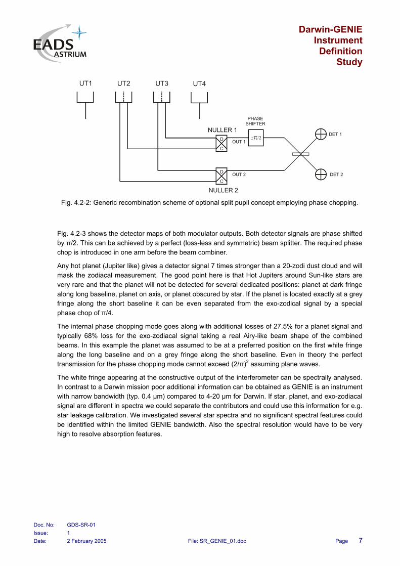
This concept is thought as a low-effort extension of the baseline Bracewell configuration. The thermal background is subtracted by forming the difference of both phase modulator outputs. This almost perfect background cancelling makes this option a good candidate for zodiacal dust detection. Zodiacal signals are the weakest signals we expect and require always telescopes of maximum size. Fig. 4.2-1 shows the accommodation on the VLTI and Fig. 4.2-2 sketches the generic recombination scheme. Now, two sub-interferometers are formed from two telescopes by pupil splitting. We need two nulling devices and both nulling outputs are fed to a phase modulator chopping the phase. The central star is always nulled in both outputs but the amount of zodiacal light can be varied by adjusting the phase jump.
Detector DET1 gives e.g. the sum of star leakage, planet signal, exo-zodiacal signal, and the dominating background signal. Detector DET2 now provides the planet leakage, the zodiacal leakage signal, and again the masking background signal. Forming the difference DET1-DET2 yields the zodiacal signal, the planetary signal, and the star leakage. Careful calibration of stellar leakage and planetary signal finally gives the zodiacal signal alone. This signal is the big unknown in current Darwin scenarios and needs further investigation before Darwin is launched. It is a second priority goal of the ground-based GENIE instrument.
Fig. 4.2-1: Site architecture for optional split pupil nuller as an extension to the standard Bracewell baseline.
Darwin-GENIE Instrument
Definition Study
Doc. No: GDS-SR-01 Issue: 1 Date: 2 February 2005 File: SR_GENIE_01.doc Page 7
UT2 UT3 UT4UT1
D
C
D
C
NULLER 1
NULLER 2
OUT 1
OUT 2 DET 2
DET 1
PHASESHIFTER
Fig. 4.2-2: Generic recombination scheme of optional split pupil concept employing phase chopping.
Fig. 4.2-3 shows the detector maps of both modulator outputs. Both detector signals are phase shifted by π/2. This can be achieved by a perfect (loss-less and symmetric) beam splitter. The required phase chop is introduced in one arm before the beam combiner.
Any hot planet (Jupiter like) gives a detector signal 7 times stronger than a 20-zodi dust cloud and will mask the zodiacal measurement. The good point here is that Hot Jupiters around Sun-like stars are very rare and that the planet will not be detected for several dedicated positions: planet at dark fringe along long baseline, planet on axis, or planet obscured by star. If the planet is located exactly at a grey fringe along the short baseline it can be even separated from the exo-zodical signal by a special phase chop of π/4.
The internal phase chopping mode goes along with additional losses of 27.5% for a planet signal and typically 68% loss for the exo-zodiacal signal taking a real Airy-like beam shape of the combined beams. In this example the planet was assumed to be at a preferred position on the first white fringe along the long baseline and on a grey fringe along the short baseline. Even in theory the perfect transmission for the phase chopping mode cannot exceed (2/π)2 assuming plane waves.
The white fringe appearing at the constructive output of the interferometer can be spectrally analysed. In contrast to a Darwin mission poor additional information can be obtained as GENIE is an instrument with narrow bandwidth (typ. 0.4 µm) compared to 4-20 µm for Darwin. If star, planet, and exo-zodiacal signal are different in spectra we could separate the contributors and could use this information for e.g. star leakage calibration. We investigated several star spectra and no significant spectral features could be identified within the limited GENIE bandwidth. Also the spectral resolution would have to be very high to resolve absorption features.

Darwin-GENIE Instrument
Definition Study
Doc. No: GDS-SR-01 Issue: 1 Date: 2 February 2005 File: SR_GENIE_01.doc Page 8
DET1 map DET2 map
DET1-DET2 map
Fig. 4.2-3: Detector signals as a function of angular offset (maps) showing a signifi-cant exo-zodiacal signal after subtraction of both modulator outputs.

Darwin-GENIE Instrument
Definition Study
Doc. No: GDS-SR-01 Issue: 1 Date: 2 February 2005 File: SR_GENIE_01.doc Page 9
4.3 Conceptual Layout of GENIE and Proposed Implementation
The conceptual layout of the GENIE instrument is shown in Fig. 4.3-1 and is based on four control loops stabilising OPD (red), intensity (blue), dynamic atmospheric longitudinal dispersion (green), and beam alignment (purple). The practical implementation is given in Fig. 4.3-2.
The OPD is stabilised with the aid of a grey fringe tracker working in-band. One half of the available power is split off by polarisation decoupling. A quarter waveplate in one arm together with polarisers behind the beam combiner performs the required decoupling. For symmetry reasons one λ/8 waveplate in each arm is proposed with the main axis rotated by 90 degrees. The intensity of each arm is used as well to normalise the control signal and to make it independent on the level of the input signal. The fringe tracker locks on half of the intensity of the full constructive signal and that is why it is called grey fringe tracker.
The intensity is stabilised by sensing a small portion (10%) of each beam in front of the beam combiner.
The longitudinal atmospheric dispersion is composed of a big static component coming from the VLTI's main delay line operating in air and a small dynamic component originating mainly from the different water vapour content in both air columns above the main telescopes. This in-band dynamic contribution is compensated by an own control loop deriving its control signal from the dispersed OPD control signal. Static and dynamic dispersion compensation is performed by dispersive wedges acting as a first order compensation. The static dispersion is adjusted by an accurate atmospheric model including temperature, pressure, and humidity, all parameters measured in the delay line tunnel. The dispersive wedges are used as well to maintain the required differential phase shift of 3π/4 (UT and most AT pairs) respectively -π/4 (special AT pairs) depending on the telescope pair used. Together with the quarter wave plate a total differential phase shift of π is established.
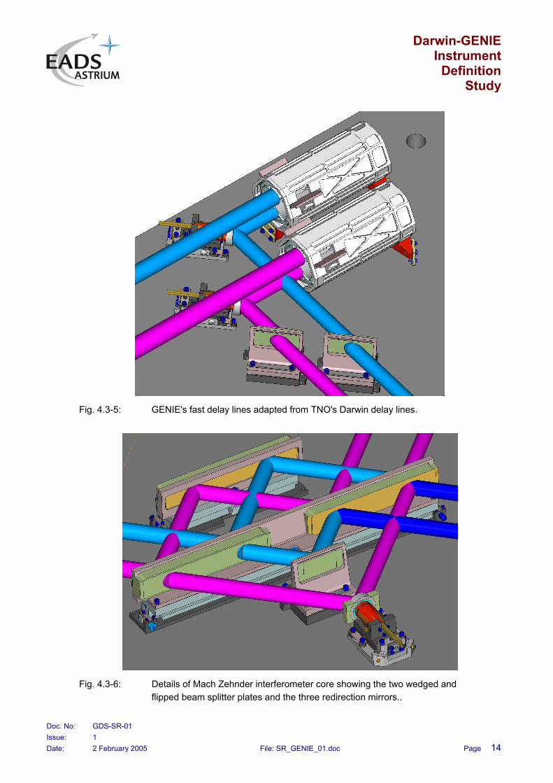
The beam combiner is built around a highly symmetric and autobalancing Mach-Zehnder interferometer core. It uses two identical but flipped beam splitter plates. Each beam experiences one transmission and one reflection on the beam splitter and makes the system insensitive to splitting layer variations. The achromatic output of the Mach Zehnder combiner is characterised by zero internal phase shift and needs an external phase shifter provided by the dispersive wedges as described before.
The beam alignment is actively controlled using a different wavelength (J-band). It compensates any misalignment coming from the VLTI itself, the pupil derotator at the input, the moving dispersive wedges, and GENIE's internal fast delay lines.
All detectors are equipped with single mode fibres for wavefront filtering. The scientific and some of the control signals are spectrally dispersed with prisms. Two detectors are foreseen, one fast control detector operating at a sampling frequency of 12 kHz maximum and a slow scientific detector read out typically once every second. Only the detectors themselves, the spectrometer prisms, and the final part of the single mode fibres are cryogenically cooled by liquid nitrogen in a Dewar. We use two identical Hawaii-I RG detectors from Rockwell. Both devices are read out by the approved standard IRACE hardware.

Darwin-GENIE Instrument
Definition Study
Doc. No: GDS-SR-01 Issue: 1 Date: 2 February 2005 File: SR_GENIE_01.doc Page 10
CONSTRUCTIVEOUTPUTS
INTENSITYMEASUREMENT
ARM 2
FILTER
POLARIZERLENS
PZT
FAST OPD CONTROL
UT 2
UT 3
BEAMSCRATCHER
NULLINGOUTPUTS
INTENSITYMEASUREMENT
ARM 1
CALIBRATIONSHUTTERS
CCDINTENSITYCONTROL
NULLER UNITL'-BAND
OPD CONTROLL'-BAND
LDC 1 + 3 /4 PHASE
SHIFTERπ
λ/8 PLATES
10%
10%
SM-FIBREBUNDLES
POLARIZINGCUBES
DYNAMICDISPERSION
CONTROL
PUPILDEROTATOR
BRACEWELL MODEVIRTUAL CHOPPING
REMOVABLEFLIP MIRROR
SUBAPERTURESELECTION
PZT
PHASECHOPPING
PHASEMODULATOR 1
ZODIACAL MODEMODULATOR OUTPUT 1
MODULATOROUTPUT 2
SUBAPERTURESELECTION
PZT
PHASECHOPPING
PHASEMODULATOR 2
MODULATOROUTPUT 3
MODULATOROUTPUT 4
LDC 2 + 3 /4 PHASE
SHIFTERπ
DISPERSIONMODEL
ANGLETRACKER
J-BAND
Fig. 4.3-1: Conceptual GENIE layout including the Bracewell baseline and the optional split pupil nuller dedicated for exo-zodiacal light from dust clouds.

Darwin-GENIE Instrument
Definition Study
Doc. No: GDS-SR-01 Issue: 1 Date: 2 February 2005 File: SR_GENIE_01.doc Page 11
The split pupil nuller option is added to the baseline Bracewell configuration by flipping in a redirection mirror behind the central beam combiner and reutilising the grey fringe tracker for the common beam path up to the combiner. The pupil is split behind the central beam combiner and a final phase modulating stage is added. Phase chopping is accomplished by periodically moving a piezo mounted mirror and wobbling the OPD in one arm. Both arms of the sub interferometers are finally combined at a symmetric beam combiner and form the two outputs shifted in phase by 90 degree. All outputs from the baseline Bracewell (2 nulling outputs and 2 constructive outputs) and from the split pupil extension are used to maximise the total efficiency. The common optical path up to the first Mach Zehnder beam combiner is stabilised by the grey fringe tracker. The remaining optical path from the common beam combiner up to the phase modulator beam combiner is not actively controlled as the beams are routed parallel and the path lengths are short. Nevertheless a residual OPD error exists and is included in the error budget. This error contribution can be reduced by increasing the integration time.
We finally arrived at an elegant design with reduced complexity as no internal laser metrology is needed. The split pupil nuller is designed as an add-on option and can be realised in a later stage during the realisation of GENIE.
The dominating thermal background radiation is subtracted by virtual chopping in the baseline Bracewell mode and is almost perfectly cancelled by the phase chopping technique of the split pupil nuller mode. 14 scientific single mode fibres and 12 background sensing single mode fibres are foreseen as wavefront filters.
The fast GENIE delay line is composed around TNO's Darwin delay line with modifications to cover the required high bandwidth. It uses a cat's eye delay line slowly moved as a whole and equipped with magnetic bearings. The fast MACAO residuals are compensated by a fast section of the delay line. The secondary flat mirror of the cat's eye is mounted on a piezo stack. This concept is best suited up to a bandwidth of more more than 20 kHz and this has been confirmed by Astrium in the course of the past nulling breadboard activity.
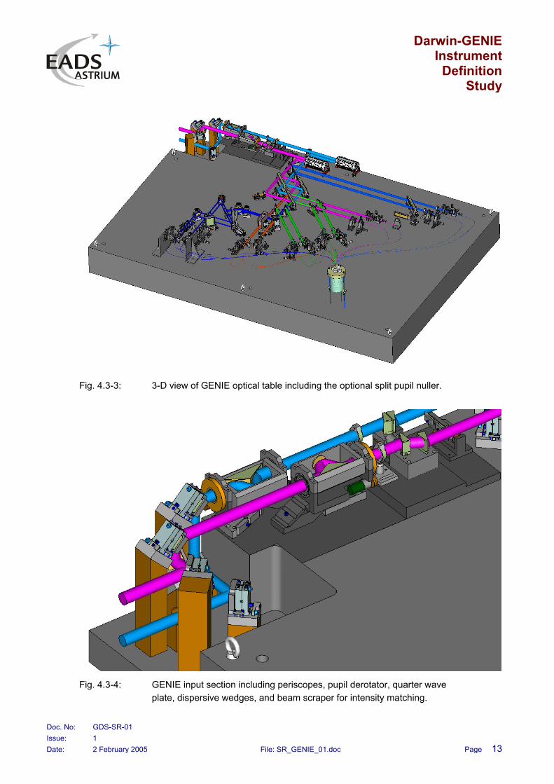
Fig. 4.3-3 to Fig. 4.3-6 show 3-dimensional drawings of the entire optical table, the GENIE input section, the fast delay lines, and the Mach Zehnder core. The dimensions of the table are 240 cm in length and 181 cm on width.

Darwin-GENIE Instrument
Definition Study
Doc. No: GDS-SR-01 Issue: 1 Date: 2 February 2005 File: SR_GENIE_01.doc Page 12
Intensity measurement
fibres function nr = signal + backgrndBracewellsplit pupil null 4 = 4 + 0constructive 4 = 2 + 2OPD/LDC control 6 = 4 + 2intensity control 6 = 2 + 4
total nr. of fibers 26
null 6 = 2 + 4
Delay lines
Pupil derotators Intensity
matcher
Beam angle sensor
10% splitters
Phaseshifter
Alignmentmirrors
λ /8 plates
MirrorPolarizerBrewsterplateλ /8 plateLens
Beam splitterBeam combinerTranslation actuatorPrism mirrorOut of plane folding mirrorsMask
Tip-tilt actuator
Cold box
high dispersion
low dispersion
spectral band filterHawaii-1 RG
Fig. 4.3-2: Proposed implementation of conceptual GENIE layout including the Bracewell baseline and the optional split pupil nuller.
Darwin-GENIE Instrument
Definition Study
Doc. No: GDS-SR-01 Issue: 1 Date: 2 February 2005 File: SR_GENIE_01.doc Page 13
Fig. 4.3-3: 3-D view of GENIE optical table including the optional split pupil nuller.
Fig. 4.3-4: GENIE input section including periscopes, pupil derotator, quarter wave plate, dispersive wedges, and beam scraper for intensity matching.
Darwin-GENIE Instrument
Definition Study
Doc. No: GDS-SR-01 Issue: 1 Date: 2 February 2005 File: SR_GENIE_01.doc Page 14
Fig. 4.3-5: GENIE's fast delay lines adapted from TNO's Darwin delay lines.
Fig. 4.3-6: Details of Mach Zehnder interferometer core showing the two wedged and flipped beam splitter plates and the three redirection mirrors..
Darwin-GENIE Instrument
Definition Study
Doc. No: GDS-SR-01 Issue: 1 Date: 2 February 2005 File: SR_GENIE_01.doc Page 15
5 GENIE KEY COMPONENTS
5.1 Detectors
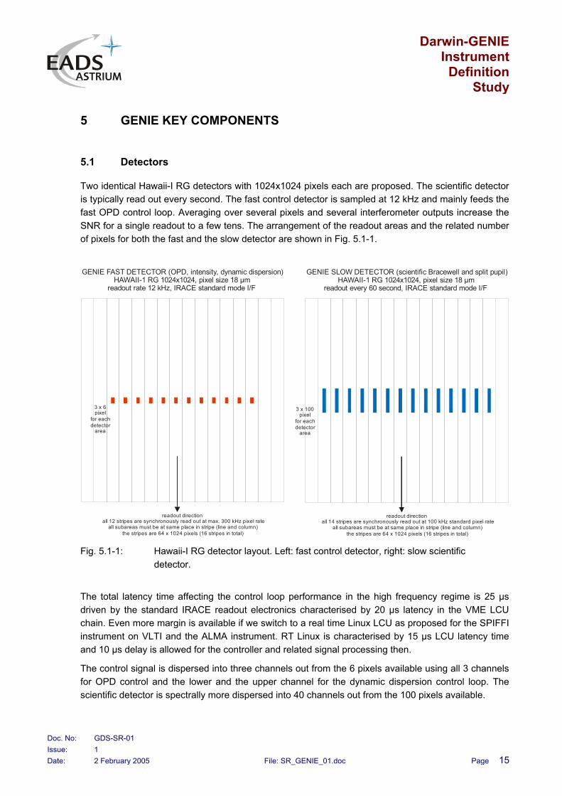
Two identical Hawaii-I RG detectors with 1024x1024 pixels each are proposed. The scientific detector is typically read out every second. The fast control detector is sampled at 12 kHz and mainly feeds the fast OPD control loop. Averaging over several pixels and several interferometer outputs increase the SNR for a single readout to a few tens. The arrangement of the readout areas and the related number of pixels for both the fast and the slow detector are shown in Fig. 5.1-1.
3 x 6pixel
for eachdetector
area
readout directionall 12 stripes are synchronously read out at max. 300 kHz pixel rate
all subareas must be at same place in stripe (line and column)the stripes are 64 x 1024 pixels (16 stripes in total)
GENIE FAST DETECTOR (OPD, intensity, dynamic dispersion)HAWAII-1 RG 1024x1024, pixel size 18 µm
readout rate 12 kHz, IRACE standard mode I/F
3 x 100pixel
for eachdetector
area
readout directionall 14 stripes are synchronously read out at 100 kHz standard pixel rate
all subareas must be at same place in stripe (line and column)the stripes are 64 x 1024 pixels (16 stripes in total)
GENIE SLOW DETECTOR (scientific Bracewell and split pupil)HAWAII-1 RG 1024x1024, pixel size 18 µm
readout every 60 second, IRACE standard mode I/F
Fig. 5.1-1: Hawaii-I RG detector layout. Left: fast control detector, right: slow scientific detector.
The total latency time affecting the control loop performance in the high frequency regime is 25 µs driven by the standard IRACE readout electronics characterised by 20 µs latency in the VME LCU chain. Even more margin is available if we switch to a real time Linux LCU as proposed for the SPIFFI instrument on VLTI and the ALMA instrument. RT Linux is characterised by 15 µs LCU latency time and 10 µs delay is allowed for the controller and related signal processing then.
The control signal is dispersed into three channels out from the 6 pixels available using all 3 channels for OPD control and the lower and the upper channel for the dynamic dispersion control loop. The scientific detector is spectrally more dispersed into 40 channels out from the 100 pixels available.

Darwin-GENIE Instrument
Definition Study
Doc. No: GDS-SR-01 Issue: 1 Date: 2 February 2005 File: SR_GENIE_01.doc Page 16
The preamplifiers for both Hawaii detectors is cooled too and feed standard and approved 14-bit ADCs sampled at 500 kHz maximum. One VME card provides already 16 channels and is sufficient for GENIE.
The tip-tilt angle sensor is based on an InGaAs CCD with 256x256 pixels operating in J band. It is thermo-electrically cooled by a Peltier device. Pixel interpolation by a factor 20 is applied to obtain the design resolution of 0.5 arcsec rms.
5.2 Beam Splitters
The Mach Zehnder core forms the heart of the GENIE instrument and needs two identical but flipped splitter plates. The plates made of ZnSe need a wedge angle of 4 arcsec to avoid ghost images on the detectors. The splitting and AR layers are not critical as auto-balancing is ensured by design. The layers must be identical on both plates for perfect symmetry and one manufacturing process with subsequent bi-section is recommended.
Two Mach Zehnder cores are required: one for the interferometer and an identical device is part of the source simulator used for testing and adjusting. The source simulator is based on the amplitude division principle and delivers two intensity balanced output beams from one source beam. The principle has been successfully verified during Astrium's nulling breadboard activity.
The phase modulator for the split pupil nuller option needs a beam combiner with inherent phase shift of 90 degrees. This is ensured only for perfectly loss-less and symmetric combiners. We propose to use an FTIR splitter with an airgap of nearly λ/8 between two identical bulk plates made of ZnSe. It has to be wedged as well to avoid ghosts. It is loss-less as no absorbing splitter layer is required and symmetric by design. The principle has been successfully used in the BLINC device for the MMT and LBT.
5.3 Wavefront Filter
EADS Astrium recently demonstrated single mode behaviour in chalcogenide glass fibres (GAST). The required mode suppression has been verified in a test interferometer. Special immersion coating is required to strip off all cladding modes. We measured an attenuation of 5 dB/m and further improvements are expected by optimising the manufacturing process. The fibre can be drawn and good core geometry and arbitrary lengths are obtained. The facets need to be AR-coated to reduce the Fresnel losses (n = 2.87).
5.4 Phase Shifter
The Mach Zehnder core is a highly symmetric two-plate beam combiner and provides no phase shift for the achromatic outputs. Hence, we need an external and achromatic phase shift of π to get destructive interference. The quarter waveplate used to decouple fringe tracker and scientific signal at orthogonal polarisations introduces already a phase shift of π/4. The remaining phase shift of 3π/4 is provided by dispersive plates arranged as first order system. Perfect phase match can be achieved at two distinct wavelengths designed at 7% of the total bandwidth. A null depth of better than 3x10⁻⁶ is
Darwin-GENIE Instrument
Definition Study
Doc. No: GDS-SR-01 Issue: 1 Date: 2 February 2005 File: SR_GENIE_01.doc Page 17
achieved then over the 10% operating bandwidth of GENIE. Off-zenith looking of the instrument introduces another asymmetry in both interferometer arms due to the air mass of the main delay line. This additional dispersion is different from the ZnSe material and yields a higher order system with even better star suppression than the zenith looking scenario as a worst case.
Special AT configurations using one telescope from the northern and one from the southern VLTI area are characterised by an inherent phase shift of π coming from a periscope in the VLTI beam train. Then the required phase shift is -π/4 to achieve destructive interference. Also negative phase shifts can be adjusted as the practical implementation uses two moveable wedges in each arm.
The dispersive phase shifter always introduce a static residual OPD error amounting to 2.6 nm for the zenith looking system and including the error from the quarter waveplate. This error is accounted for in GENIE's error budget.
5.5 Main Delay Line and Related Air Mass
The VLTI is equipped with delay lines operating in normal air and the resulting longitudinal static atmospheric dispersion must be compensated by the dispersive wedge phase shifter system as well. We propose an open loop correction by atmospheric model. Pressure, temperature, relative humidity, and zenith angle serve as input to the model and must be permanently monitored.
5.6 Control Loops
Four different control loops are implemented. Most of them are single-stage PI-controllers (OPD and tip-tilt) but also more sophisticated three-stage controllers (intensity and dispersion control loop). The latter controllers are designed as a basic PI-stage cascaded with two integrator stages. Sufficient phase margin must be provided at high frequencies to suppress the residual noise by the aid of high open loop gain. In particular for near target stars all external noise contributors can be reasonably suppressed and the sensor noise dominates the performance. Typical instrument transmissions are given in the table below. A quantum efficiency of 65% has been assumed for the detectors.
The sampling rates of the digital control loops have been optimised with GENIEsim and yielded typically 12 kHz for the fast OPD controller, 290 Hz for the intensity control loop, 200 Hz for the dispersion control loop, and 55 Hz for the tip-tilt controller.
INSTRUMENT TRANSMISSION - SCIENCE CHANNELS
Bracewell mode 3.2%
Split pupil mode planet: 1 % zodi: 0.5%
INSTRUMENT TRANSMISSION - CONTROL CHANNELS
Intensity 0.5%
OPD 2.2%
Dynamic dispersion 0.7%

Darwin-GENIE Instrument
Definition Study
Doc. No: GDS-SR-01 Issue: 1 Date: 2 February 2005 File: SR_GENIE_01.doc Page 18
6 PERFORMANCE ESTIMATE
Extensive performance simulations have been carried out and the key figures describing GENIE's performance were gained. We used in-house simulation tools and GENIEsim provided by ESA for this study and widely used in the community. We calculated the SNR and included photon noise, instrumental (transmission) noise, calibration noise, and detector noise.
In particular the calibration noise is a principle performance limit and cannot be improved by longer integration times. In contrast, instrumental noise can be reduced over time very well. All signal contributions need proper calibration and these errors for zodiacal light, stellar leakage, and background light put a fundamental limit on the obtainable SNR.
The most important result is shown in Fig. 6-1. A SNR of 5 is achieved within minutes of integration time for the baseline Bracewell mode. The split pupil nuller needs already hours to obtain the same performance. The reason for that is the additional OPD error between Mach Zehnder beam combiner (baseline section of GENIE) and the phase modulator and beam combiner within the split pupil nuller section. We decided for the option to avoid any internal laser metrology in return to an elegant design with reduced complexity.
We also simulated the performance of the split pupil nuller with internal laser metrology included and the required integration times are comparable then to the baseline solution.
We established an error budget for the GENIE instrument including static errors coming from star leakage, all four control loops, beam rotation, lateral pupil shift, differential polarisation, and dispersive phase shifter. Dynamic errors like fluctuations in OPD, dispersion, intensity, and beam tip-tilt are added in a second step. The overall performance has been evaluated for 10% and 20% bandwidth of GENIE with a little advantage for the narrow-banded system.
We showed that Hot Jupiters can be detected around Sun-like stars up to a distance of 38 pc (mL' = 6). Hot planets may be observed within minutes, far-distance planets require integration times of hours.
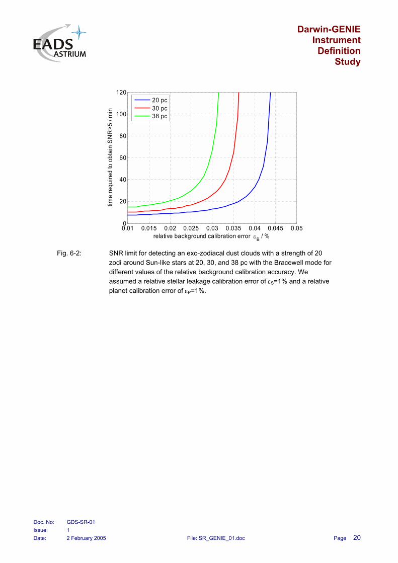
We also estimated the required background calibration accuracy for the baseline Bracewell mode with the result that an accuracy better than 0.4% is typically needed (see Fig. 6-2).

Darwin-GENIE Instrument
Definition Study
Doc. No: GDS-SR-01 Issue: 1 Date: 2 February 2005 File: SR_GENIE_01.doc Page 19
Bracewell mode Split-pupil mode
SNR for long integration time
10 15 20 25 30 35 400
10
20
30
40
50
60
70
distance / pc
SN
R li
mit
20 zodi30 zodi40 zodi50 zodi100 zodi
10 15 20 25 30 35 400
10
20
30
40
50
60
70
distance / pc
SN
R li
mit
20 zodi30 zodi40 zodi50 zodi100 zodi
Bracewell mode Split-pupil mode
Required integration time for SNR > 5
10 15 20 25 30 35 400
2
4
6
8
10
12
14
16
distance / pc
time
requ
ired
to o
btai
n S
NR
>5 /
min
20 zodi30 zodi40 zodi50 zodi100 zodi
10 15 20 25 30 35 400
2
4
6
8
10
12
distance / pc
time
requ
ired
to o
btai
n S
NR
>5 /
h
20 zodi30 zodi40 zodi50 zodi100 zodi
Fig. 6-1: SNR limit and required integration time for detecting exo-zodiacal dust clouds with the Bracewell and the split-pupil mode mode. We assumed a relative stellar leakage calibration error of εS=1% and a relative planet calibration error of εP=1%. For the Bracewell mode we assumed a relative background calibration accuracy of εB=0.01%. For the split-pupil mode we assumed 100 nm internal rms OPD error. Please note the different time scaling in the bottom graphs.
Darwin-GENIE Instrument
Definition Study
Doc. No: GDS-SR-01 Issue: 1 Date: 2 February 2005 File: SR_GENIE_01.doc Page 20
0.01 0.015 0.02 0.025 0.03 0.035 0.04 0.045 0.050
20
40
60
80
100
120
relative background calibration error εB / %
time
requ
ired
to o
btai
n S
NR
>5 /
min
20 pc30 pc38 pc
Fig. 6-2: SNR limit for detecting an exo-zodiacal dust clouds with a strength of 20 zodi around Sun-like stars at 20, 30, and 38 pc with the Bracewell mode for different values of the relative background calibration accuracy. We assumed a relative stellar leakage calibration error of εS=1% and a relative planet calibration error of εP=1%.

Darwin-GENIE Instrument
Definition Study
Doc. No: GDS-SR-01 Issue: 1 Date: 2 February 2005 File: SR_GENIE_01.doc Page 21
7 CONCLUSIONS AND RECOMMENDATION
The GENIE instrument proposed by EADS Astrium is able to detect 20-zodi dust clouds within a reasonable time and SNR greater than 1 can be achieved. We demonstrated that both the baseline Bracewell as well as the optional split pupil nuller extension can deliver the same measurement results. The baseline version provides the results faster as the additional and not corrected OPD error of the split pupil nuller extension needs more integration time for the same performance.
We also simulated the scenario with internal laser metrology up to the split pupil nulling beam combiner and got comparable results to the Bracewell baseline configuration. The integration times to achieve the same SNR are very similar then.
Concluding we can say that the split pupil nuller option does not give better or new results but we can save with this approach the background calibration and its residual error. On the other hand the added complexity of a split pupil nuller with phase chopper is remarkable. Hence, we propose to continue with the baseline solution, a 2-telescope Bracewell with in-band grey fringe tracker for OPD stabilisation.