d3.3 report “integrating hydrogen in existing refuelling infrastructure”
TRANSCRIPT
WP3 DELIVERABLE D3.3 - “Integrating hydrogen in existing refuelling infrastructure”
Final Report |Dissemination level: PU
Page 1 of 7
D3.3 Report “Integrating hydrogen
in existing refuelling infrastructure”
Final Report
Dissemination level: PU
WP3 DELIVERABLE D3.3 - “Integrating hydrogen in existing refuelling infrastructure”
Final Report |Dissemination level: PU
Page 2 of 7
WP3 Deliverable D3.3
“Integrating hydrogen in existing refuelling infrastructure”
As part of the FCH-JU supported demonstration project, H2 MOVES Scandinavia an effort has been
conducted in identifying a site for a new hydrogen refuelling station (HRS) in Oslo and ensure optimal
integration with the existing network of HRS’s in the City.
This report provides the results of the extensive analysis conducted in selection the site as well as
placing of the HRS at the site. The report acts as the outcome of the deliverable D3.3 in the project.
1. Background, the Scandinavian & Oslo HRS network
The new Oslo HRS would become part of the growing HRS network in Scandinavia. The site process in
Oslo could therefore was build on the many experiences from past HRS placements in Scandinavia.
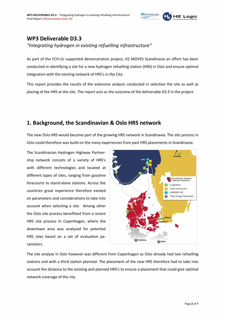
The Scandinavian Hydrogen Highway Partner-
ship network consists of a variety of HRS’s
with different technologies and located at
different types of sites, ranging from gasoline
forecourts to stand-alone stations. Across the
countries great experience therefore existed
on parameters and considerations to take into
account when selecting a site. Among other
the Oslo site process benefitted from a recent
HRS site process in Copenhagen, where the
downtown area was analysed for potential
HRS sites based on a set of evaluation pa-
rameters.
The site analyse in Oslo however was different from Copenhagen as Oslo already had two refuelling
stations and with a third station planned. The placement of the new HRS therefore had to take into
account the distance to the existing and planned HRS’s to ensure a placement that could give optimal
network coverage of the city.
WP3 DELIVERABLE D3.3 - “Integrating hydrogen in existing refuelling infrastructure”
Final Report |Dissemination level: PU
Page 3 of 7
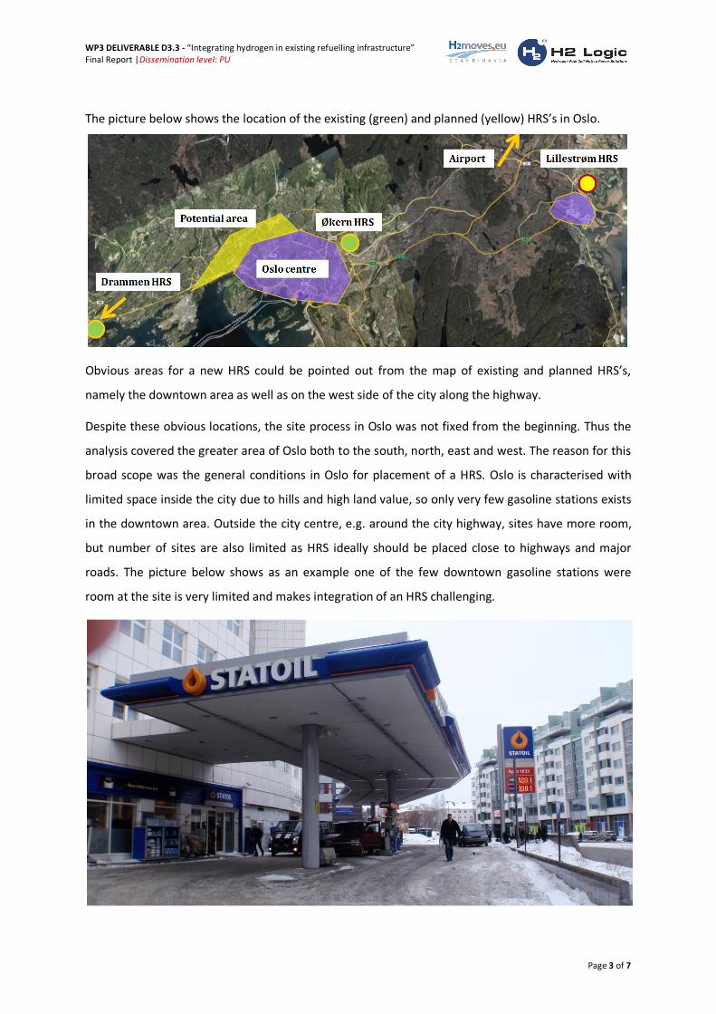
The picture below shows the location of the existing (green) and planned (yellow) HRS’s in Oslo.
Obvious areas for a new HRS could be pointed out from the map of existing and planned HRS’s,
namely the downtown area as well as on the west side of the city along the highway.
Despite these obvious locations, the site process in Oslo was not fixed from the beginning. Thus the
analysis covered the greater area of Oslo both to the south, north, east and west. The reason for this
broad scope was the general conditions in Oslo for placement of a HRS. Oslo is characterised with
limited space inside the city due to hills and high land value, so only very few gasoline stations exists
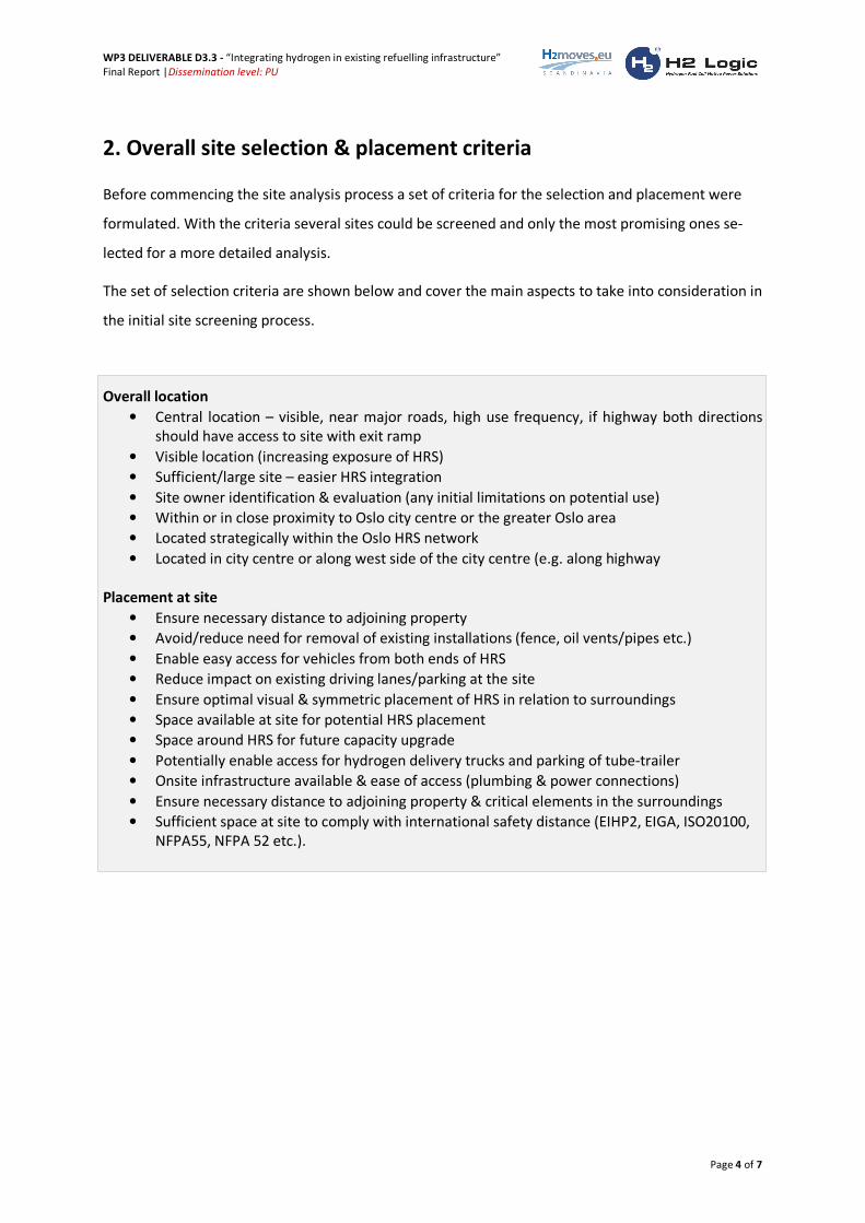
in the downtown area. Outside the city centre, e.g. around the city highway, sites have more room,
but number of sites are also limited as HRS ideally should be placed close to highways and major
roads. The picture below shows as an example one of the few downtown gasoline stations were
room at the site is very limited and makes integration of an HRS challenging.
WP3 DELIVERABLE D3.3 - “Integrating hydrogen in existing refuelling infrastructure”
Final Report |Dissemination level: PU
Page 4 of 7
2. Overall site selection & placement criteria
Before commencing the site analysis process a set of criteria for the selection and placement were
formulated. With the criteria several sites could be screened and only the most promising ones se-
lected for a more detailed analysis.
The set of selection criteria are shown below and cover the main aspects to take into consideration in
the initial site screening process.
Overall location
• Central location – visible, near major roads, high use frequency, if highway both directions
should have access to site with exit ramp
• Visible location (increasing exposure of HRS)
• Sufficient/large site – easier HRS integration
• Site owner identification & evaluation (any initial limitations on potential use)
• Within or in close proximity to Oslo city centre or the greater Oslo area
• Located strategically within the Oslo HRS network
• Located in city centre or along west side of the city centre (e.g. along highway
Placement at site
• Ensure necessary distance to adjoining property
• Avoid/reduce need for removal of existing installations (fence, oil vents/pipes etc.)
• Enable easy access for vehicles from both ends of HRS
• Reduce impact on existing driving lanes/parking at the site
• Ensure optimal visual & symmetric placement of HRS in relation to surroundings
• Space available at site for potential HRS placement
• Space around HRS for future capacity upgrade
• Potentially enable access for hydrogen delivery trucks and parking of tube-trailer
• Onsite infrastructure available & ease of access (plumbing & power connections)
• Ensure necessary distance to adjoining property & critical elements in the surroundings
• Sufficient space at site to comply with international safety distance (EIHP2, EIGA, ISO20100,
NFPA55, NFPA 52 etc.).
WP3 DELIVERABLE D3.3 - “Integrating hydrogen in existing refuelling infrastructure”
Final Report |Dissemination level: PU
Page 5 of 7
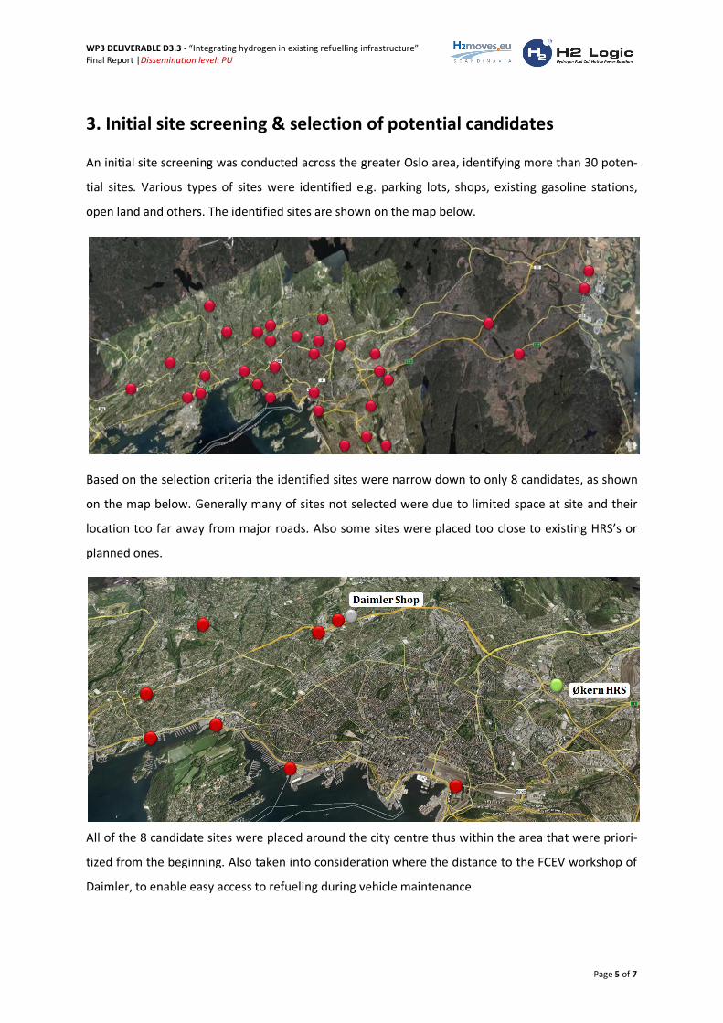
3. Initial site screening & selection of potential candidates
An initial site screening was conducted across the greater Oslo area, identifying more than 30 poten-
tial sites. Various types of sites were identified e.g. parking lots, shops, existing gasoline stations,
open land and others. The identified sites are shown on the map below.
Based on the selection criteria the identified sites were narrow down to only 8 candidates, as shown
on the map below. Generally many of sites not selected were due to limited space at site and their
location too far away from major roads. Also some sites were placed too close to existing HRS’s or
planned ones.
All of the 8 candidate sites were placed around the city centre thus within the area that were priori-
tized from the beginning. Also taken into consideration where the distance to the FCEV workshop of
Daimler, to enable easy access to refueling during vehicle maintenance.
WP3 DELIVERABLE D3.3 - “Integrating hydrogen in existing refuelling infrastructure”
Final Report |Dissemination level: PU
Page 6 of 7
4. Detailed analysis of candidate sites & selection of final
Each of the 8 candidate sites were analysed in detail, still using the overall selection criteria, but now
also looking into details of e.g. potential placement of the HRS at the site.
In particular sites were analysed for their ability to enable a convenient placement of the HRS whilst
taking into consideration the safety distances. This proved to be a challenge at many sites as an ideal
placement of the HRS with regards to easy vehicle access often required space, which again was lim-
ited and thus compliance with safety distances became difficult.
Also considerations on distance to city centre and existing HRS’s were analyzed for each site as well
as their location with respected too easy access from major roads.
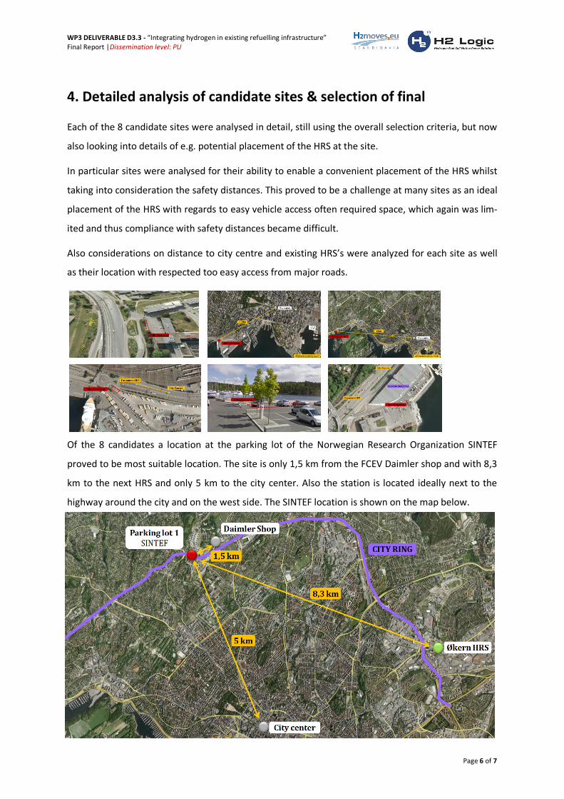
Of the 8 candidates a location at the parking lot of the Norwegian Research Organization SINTEF
proved to be most suitable location. The site is only 1,5 km from the FCEV Daimler shop and with 8,3
km to the next HRS and only 5 km to the city center. Also the station is located ideally next to the
highway around the city and on the west side. The SINTEF location is shown on the map below.
WP3 DELIVERABLE D3.3 - “Integrating hydrogen in existing refuelling infrastructure”
Final Report |Dissemination level: PU
Page 7 of 7
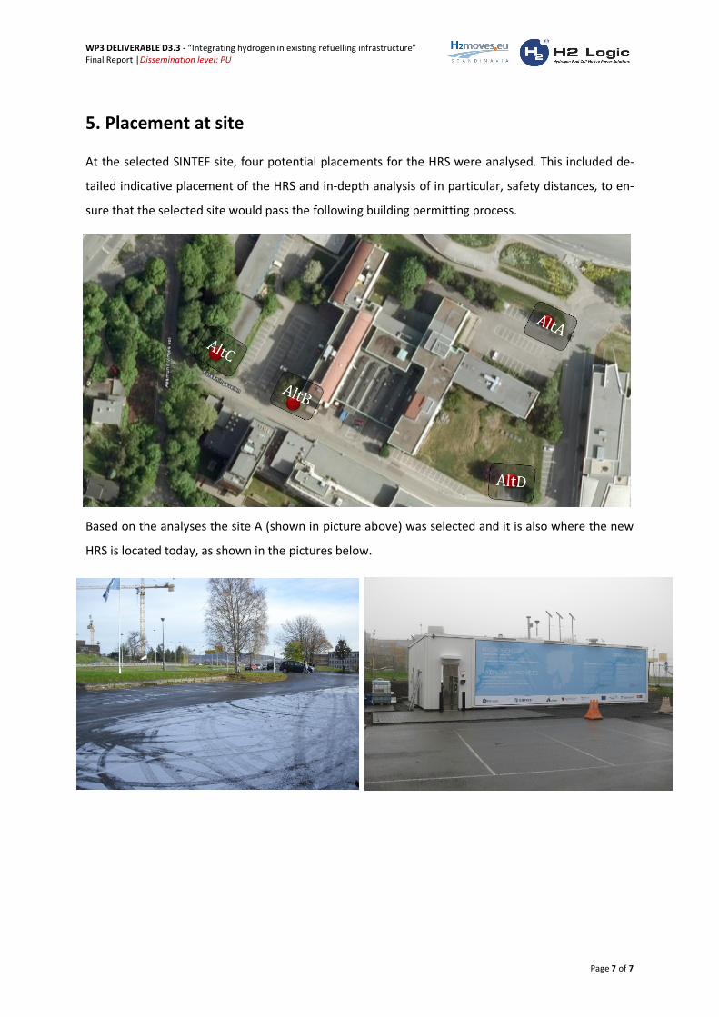
5. Placement at site
At the selected SINTEF site, four potential placements for the HRS were analysed. This included de-
tailed indicative placement of the HRS and in-depth analysis of in particular, safety distances, to en-
sure that the selected site would pass the following building permitting process.
Based on the analyses the site A (shown in picture above) was selected and it is also where the new
HRS is located today, as shown in the pictures below.