d2.6 wireless consist network report
TRANSCRIPT

D2.6 – Wireless Consist Network Report
Project number: 826073
Project acronym: Safe4RAIL-2
Project title: SAFE architecture for Robust distributed
Application Integration in rolling stock 2
Start date of the project: 1st October 2018
Duration: 34 months
Programme: H2020-S2RJU-OC-2018
Deliverable type: Report
Deliverable reference number: ICT-826073 / D2.6/ 1.0
Work package WP 2
Due date: July 2021 – M34
Actual submission date: 29th July 2021
Responsible organisation: IKL
Editor: Aitor Arriola
Dissemination level: Public
Revision: 1.0
Abstract: State of the Art review of wireless technologies for WLCN
Keywords: WLCN, communication technologies, wireless
This project has received funding from the European Union’s Horizon 2020 research and innovation programme under grant agreement No. 826073. The information and views set out in this document are those of the author(s) and do not necessarily reflect the official opinion of Shift2Rail Joint Undertaking. The JU does not guarantee the accuracy of the data included in this article. Neither the JU nor any person acting on the JU’s behalf may be held responsible for the use which may be made of the information contained therein.
Ref. Ares(2021)4851402 - 29/07/2021

D2.6 – Wireless Consist Network Report
Safe4RAIL-2 D2.6 Page II
Editor
Aitor Arriola (IKL)
Contributors (ordered according to beneficiary numbers)
Aitor Arriola (IKL)
Pedro Aljama (IKL)
Cristina Cruces (IKL)
Iñaki Val (IKL)
Disclaimer
The information in this document is provided “as is”, and no guarantee or warranty is given that the information is fit for any particular purpose. The content of this document reflects only the author’s view – the Joint Undertaking is not responsible for any use that may be made of the information it contains. The users use the information at their sole risk and liability.

D2.6 – Wireless Consist Network Report
Safe4RAIL-2 D2.6 Page III
Executive Summary
This deliverable presents a survey of wireless technologies for the Wireless Consist Network (WLCN), as well as the results of a wireless TSN demonstrator. In the technology survey each wireless technology is analysed in terms of bit rate, time performance and robustness, and both currently-available and more advanced solutions are considered. The main conclusion of this analysis is that none of the current technologies is able to cover all the traffic types of the WLCN, either due to their low bit rate (e.g. ZigBee, WirelessHART, ECHORING, WSAN/WISA), high latency (e.g. LTE), or non-deterministic medium access (e.g. WiFi). Some of these technologies could be suitable for specific types of TCMS traffic, but in order to cover all traffic types in the WLCN a combination of several wireless technologies would be needed. On the other hand, more advanced technologies, such as Ultra-Reliable and Low-Latency Communications (URLLC) provided by 5G, or deterministic extensions of the MAC layer of WiFi, represent a promising solution for the WLCN. One of these technologies (SHARP) combined with a wired TSN card from Safe4RAIL-2 WP1 has been used to build a wireless TSN demonstrator. This demonstrator has proven bounded latencies for Real-Time traffic as low as 510 µs with six TSN hops including wired and wireless segments.

D2.6 – Wireless Consist Network Report
Safe4RAIL-2 D2.6 Page IV
Contents
Chapter 1 Introduction ........................................................................................ 1
1.1 Scope ............................................................................................................... 1
1.2 WLCN Architecture .......................................................................................... 1
Chapter 2 State-of-the-Art .................................................................................. 3
2.1 LTE (Long Term Evolution) .............................................................................. 3
2.1.1 Bit rate ................................................................................................................... 3
2.1.2 Time considerations ............................................................................................... 3
2.1.3 Robustness/Interferences ...................................................................................... 4
2.1.4 Network Dimensions .............................................................................................. 5
2.1.5 Additional considerations ....................................................................................... 5
2.1.6 LTE in unlicensed spectrum ................................................................................... 6
2.1.7 LTE-U .................................................................................................................... 7
2.1.8 LAA ........................................................................................................................ 7
2.1.9 LWA ....................................................................................................................... 8
2.1.10 MulteFire .......................................................................................................... 8
2.2 ZigBee ............................................................................................................. 9
2.2.1 Bit rate ................................................................................................................... 9
2.2.2 Time considerations ............................................................................................... 9
2.2.3 Robustness/Interferences .....................................................................................10
2.2.4 Network Dimensions .............................................................................................11
2.2.5 Additional considerations ......................................................................................11
2.3 WirelessHART ............................................................................................... 11
2.3.1 Bit rate ..................................................................................................................11
2.3.2 Time considerations ..............................................................................................11
2.3.3 Robustness/Interferences .....................................................................................13
2.3.4 Network Dimensions .............................................................................................13
2.3.5 Additional considerations ......................................................................................14
2.4 UWB (Ultra Wide Band) ................................................................................. 14
2.4.1 Bit rate ..................................................................................................................14
2.4.2 Time considerations ..............................................................................................14
2.4.3 Robustness/Interferences .....................................................................................14
2.4.4 Network Dimensions .............................................................................................15
2.4.5 Additional considerations ......................................................................................16
2.5 Wi-Fi .............................................................................................................. 16
2.5.1 Bit rate ..................................................................................................................16

D2.6 – Wireless Consist Network Report
Safe4RAIL-2 D2.6 Page V
2.5.2 Time considerations ..............................................................................................16
2.5.3 Robustness/Interferences .....................................................................................18
2.5.4 Network Dimensions .............................................................................................19
2.5.5 Additional considerations ......................................................................................19
2.6 ECHORING ................................................................................................... 19
2.6.1 Bit rate ..................................................................................................................19
2.6.2 Time considerations ..............................................................................................20
2.6.3 Robustness/Interferences .....................................................................................21
Cooperative ARQ .........................................................................................................21
Evolved Failure Tolerance Mechanisms .......................................................................21
Adaptation of Error Handling Strategy ..........................................................................21
2.6.4 Network Dimensions .............................................................................................22
2.6.5 Additional considerations ......................................................................................22
2.7 WISA (Wireless Interface for Sensors Actuators) .......................................... 22
2.7.1 Bit rate ..................................................................................................................22
2.7.2 Time considerations ..............................................................................................23
2.7.3 Robustness/Interferences .....................................................................................23
2.7.4 Network Dimensions .............................................................................................23
2.7.5 Additional considerations ......................................................................................23
Chapter 3 Future technologies ........................................................................ 24
3.1 SHARP .......................................................................................................... 24
3.2 LTE Release 15/16 (5G) ................................................................................ 28
3.3 WirelessHP .................................................................................................... 31
3.4 Wi-Fi 6 (IEEE 802.11ax) ................................................................................ 34
Chapter 4 Technology Summary ..................................................................... 39
Chapter 5 Wireless TSN Demonstrator ........................................................... 44
5.1 Architecture .................................................................................................... 44
5.2 TSN Configuration ......................................................................................... 45
5.3 Measurement Results .................................................................................... 45
5.3.1 RT Traffic E2E latency ..........................................................................................46
5.3.2 BE Throughput Capacity .......................................................................................46
Chapter 6 Conclusions ..................................................................................... 48
Chapter 7 List of Abbreviations ....................................................................... 49
Chapter 8 References ....................................................................................... 55
Chapter 9 Annex LTE ........................................................................................ 60

D2.6 – Wireless Consist Network Report
Safe4RAIL-2 D2.6 Page VI
9.1 LTE – M and NB-IoT ...................................................................................... 63
Chapter 10 Annex ZigBee ................................................................................... 65
Chapter 11 Annex WirelessHART ...................................................................... 69
Chapter 12 Annex UWB (Ultra Wide Band) ....................................................... 70
Chapter 13 Annex Wi-Fi ...................................................................................... 72
Chapter 14 Annex ECHORING ........................................................................... 77
Chapter 15 Annex WISA ..................................................................................... 78

D2.6 – Wireless Consist Network Report
Safe4RAIL-2 D2.6 Page VII
List of Figures
Figure 1. Proposed architecture for WLCN ............................................................................ 1
Figure 2 Throughput comparative with/without femtocell [8] .................................................. 5
Figure 3 Unlicensed LTE options [11] .................................................................................... 6
Figure 4 CSAT algorithm ....................................................................................................... 7
Figure 5 Maximum Channel Occupancy Times based on access priority [13] ....................... 8
Figure 6 Latency vs. Network size (25 byte payload) [15] ...................................................... 9
Figure 7 Latency vs. Network size (50 byte payload) [15] .....................................................10
Figure 8 WirelessHART Stack [16] .......................................................................................12
Figure 9 TDMA scheme of WirelessHART ............................................................................12
Figure 10 Frequency hopping technique of WirelessHART [19] ............................................13
Figure 11 UWB pulse [21] ....................................................................................................14
Figure 12 Coexistence of UWB with narrowband and wideband signals [22] ........................15
Figure 13 UWB Emission limit [23] .......................................................................................15
Figure 14 Superframe structure [26, 27] ...............................................................................17
Figure 15. IEEE 802.11 vs IEEE 802.11e comparison [27] ...................................................18
Figure 16 Gaming application with IEEE 802.11ac [29] ........................................................18
Figure 17 Set up of a real demonstrator (ECHORING technology) .......................................20
Figure 18 Cooperative ARQ (ECHORING) [31] ....................................................................21
Figure 19 SHARP description ...............................................................................................24
Figure 20 SHARP topology [34] ............................................................................................25
Figure 21 SHARP Super-Frame ...........................................................................................25
Figure 22 IEEE 802.11g DL waveform (3 frames) ................................................................26
Figure 23 SHARP DL waveform (3 subframes) ....................................................................27
Figure 24 UL waveform (SHARP) .........................................................................................27
Figure 25 5G timeline [36] ....................................................................................................28
Figure 26 KPI summary 5G [38] ...........................................................................................29
Figure 27 NR Frame structure [40] .......................................................................................30
Figure 28 Flexible slot configuration NR [41] ........................................................................30
Figure 29 OFDM overheads in data symbols for IEEE 802.11g (with 20 MHz bandwidth) and 802.11ac (160 MHz) [42]. .............................................................................................32
Figure 30 Simulated packet transmission time in WirelessHP [42]........................................32
Figure 31 Comparison between IEEE 802.11 and WirelessHP (L= 100bits) (Packet time vs Raw data rate) [42]. ......................................................................................................33
Figure 32 Comparison between IEEE 802.11 and WirelessHP (Number of samples) [42]. ...33

D2.6 – Wireless Consist Network Report
Safe4RAIL-2 D2.6 Page VIII
Figure 33 OFDMA gain in the overlapped network scenario [43] ..........................................34
Figure 34 OFDM vs OFDMA [44] .........................................................................................35
Figure 35 HE SU PPDU format [46] ......................................................................................36
Figure 36 HE-MU (Multiple User) format [46] ........................................................................36
Figure 37 HE_EXT_SU format [46].......................................................................................36
Figure 38 HE TB PPDU format [46] ......................................................................................36
Figure 39 OBSS example .....................................................................................................37
Figure 40 BSS coloring .........................................................................................................37
Figure 41. Architecture of the Wireless TSN demonstrator ...................................................44
Figure 42. Configuration of the TSN windows in Ethernet TSN and w-SHARP .....................45
Figure 43. Safe4RAIL-2 Wireless TSN Demonstrator ...........................................................46
Figure 44 LTE releases [48] .................................................................................................60
Figure 45. OFDMA and SC-FDMA [50] ................................................................................61
Figure 46 LTE frame structure Type 1 (FDD) [51] .................................................................61
Figure 47 LTE frame structure Type 2 (TDD) [51] .................................................................62
Figure 48 Frame configuration [52] .......................................................................................62
Figure 49 CA data pipe LTE [53] ..........................................................................................63
Figure 50 CA timeline [54] ....................................................................................................63
Figure 51 NB-IoT spectrum deployment [56] ........................................................................64
Figure 52 ZigBee protocol layers [58] ...................................................................................65
Figure 53 Superframe structure IEEE 802.15.4 [60] .............................................................66
Figure 54 ZigBee devices: Coordinator (black), Routers (red), End Devices (white) [61] ......66
Figure 55 Star topology [62] .................................................................................................67
Figure 56 Tree topology [62].................................................................................................67
Figure 57 Mesh topology [62] ...............................................................................................67
Figure 58 WirelessHART topology [16] .................................................................................69
Figure 59 UWB PHY frame format [64] .................................................................................70
Figure 60 Structure of a UWB symbol [64] ............................................................................70
Figure 61 Star and peer-to-peer networks IEEE 802.15.4a ..................................................71
Figure 62 Stack protocol IEEE 802.11 ..................................................................................72
Figure 63. IEEE 802.11 general frame format ......................................................................72
Figure 64 Wi-Fi Infrastructure Mode [66] ..............................................................................73
Figure 65 BSS diagram [66] .................................................................................................73
Figure 66 ESS diagram [66] .................................................................................................73
Figure 67 Ad Hoc mode (Wi-Fi) [67]. ....................................................................................73
Figure 68 Token ring topology ..............................................................................................77
Figure 69. ECHORING evaluation kit. ..................................................................................77

D2.6 – Wireless Consist Network Report
Safe4RAIL-2 D2.6 Page IX
Figure 70 WISA frame structure [69] ....................................................................................78
Figure 71 WISA frame definition [70] ....................................................................................78
Figure 72 WISA devices [33] ................................................................................................79
Figure 73 WISA topology [69] ...............................................................................................79

D2.6 – Wireless Consist Network Report
Safe4RAIL-2 D2.6 Page 1 of 79
Chapter 1 Introduction
1.1 Scope
In the scope of Safe4Rail-2 activities, a State-of-Art wireless technology for a Wireless Consist Network (WLCN) is demanded. The main goal of the present report is to analyse the main wireless technologies which have been considered by the partners as real options to be integrated in the WLCN. This analysis is presented in Chapter 2, where key features of each wireless technology (bit rate, time, robustness/interferences) are summarized. This analysis has been completed with annexes where the more general features of each technology are described. Technologies for the future application on the WLCN are also presented in Chapter 3, and a summary including all analyzed technologies is done in Chapter 5. A demonstrator has also been built which includes a hybrid wired/wireless Time Sensitive Networking (TSN) topology; a description of this demonstrator as well as performance results are presented in Chapter 6.
1.2 WLCN Architecture
The architecture proposed by CONNECTA-2 for the WLCN is depicted in Figure 1.
Figure 1. Proposed architecture for WLCN
It is based on the IEC 61375 standard and on topology solutions provided by CONNECTA and Roll2Rail projects which defined the next generation communication network (NG-TCN) architecture. This architecture is made of two redundant wireless networks, each of them having one Wireless Access Point (WAP) per vehicle. Wireless End Devices (WEDs) will be

D2.6 – Wireless Consist Network Report
Safe4RAIL-2 D2.6 Page 2 of 79
connected to a WAP, except the Safe Wireless End Devices (WED-S), which will be connected to two WAPs (which is a safety related design approach), each one from a different wireless network, and therefore will require two wireless interfaces. On the other hand, all WAPs will be connected to Consist Switches (CS), which will be interconnected via a wired Ethernet Consist Network (ECN).
This is a suitable solution for the NG-TCN, because it eases the integration of different wireless technologies. In the future, architectures with a complete wireless CN (Consist Network) could be achieved; this would require deterministic and reliable communication for both non-safe and safe end devices.

D2.6 – Wireless Consist Network Report
Safe4RAIL-2 D2.6 Page 3 of 79
Chapter 2 State-of-the-Art
In this chapter the features of different wireless technologies will be described, focusing on three aspects that are critical for the WLCN: bit rate, time considerations and robustness. On the other hand, the general description of each technology will be included as an annex.
2.1 LTE (Long Term Evolution)
2.1.1 Bit rate
LTE-Advanced (LTE Release 10) and beyond support Carried Aggregation (CA), as detailed in Annex LTE. This is an approach for obtaining wider transmission bandwidths (up to 100 MHz) and higher data rates. CA can be used either for FDD and TDD modes, and for both Uplink and Downlink.
Regarding the bit rate, the concept of UE (User Equipment) Category must be considered. The UE category defines the combination of Uplink and Downlink performance capabilities. In LTE technical specification Release 14 (see [1]), the UE categories and their maximum data rates are detailed as follows:
UE Category Max Up Link data rate (Mbps) Max Down link data rate (Mbps)
1 ~ 5 ~ 10
2 ~ 25 ~ 51
3 ~ 51 ~ 102
4 ~ 51 ~ 150
5 ~ 75 ~ 300
6 ~ 51 ~ 301
7 ~ 102 ~ 301
8 ~ 1500 ~3000
9 ~ 51 ~ 450
10 ~ 102 ~ 450
11 ~ 51 ~ 600
12 ~ 102 ~600
Table 1 UE device categories Bit Rate[1]
UE Category 4 has been highlighted, as it is the most extended one in the market. This category implies a maximum bit rate of 51 Mbps for Uplink and 150 Mbps for Downlink.
2.1.2 Time considerations
LTE makes use of the QCI (QoS Class identifier) parameter for the management of data traffic in a network. This value specifies the order of the packets (priority), packet delay and packet loss.
In Table 2 there is an example of a QCI table, divided in GBR (Guaranteed Bit Rate) applications, where in case of congestion a minimum data rate must be guaranteed, and Non-

D2.6 – Wireless Consist Network Report
Safe4RAIL-2 D2.6 Page 4 of 79
GBR (Non-Guaranteed Bit Rate) applications, where packet losses may occur in case of congestion. This table indicates latencies between 50ms and 300ms.
Table 2 QCI example (LTE) [2, 3]
2.1.3 Robustness/Interferences
Functions for Self-Optimisation Network (SON) were included in Release 10 (LTE- Advanced)
and beyond in order to enable the nodes in the network to automatically configure, optimize
and heal themselves. Some of these functions related to network robustness are:
1. Mobility Load Balancing (MLB): it is a function for optimisation of coverage and
capacity, where those cells suffering congestion can transfer load to other cells. It
includes load reporting between base stations to exchange information about load level
and available capacity.
2. Mobility Robustness Optimization (MRO): it is a solution for automatic detection and
correction of errors in the mobility configuration. In Release 10 the focus is on errors
causing Radio Link Failure (RLF) due to a late handover, early handover, or handover
to an incorrect cell [4].

D2.6 – Wireless Consist Network Report
Safe4RAIL-2 D2.6 Page 5 of 79
2.1.4 Network Dimensions
Regarding network sizing, LTE supports 200-300 users per cell [2, 5] and covers an estimated distance of 387,80 m. This communication distance has been calculated using typical transmitter power and receiver sensitivity values, and applying the intra-consist path loss model from [6].
Transmission Power (dBm) 23
Receiver Sensitivity (dBm) -90
Link Margin (dB) 113
Communication Distance (m) 387,80
Table 3 Network dimensions (LTE)
2.1.5 Additional considerations
Alternatively, to the use of eNodeBs (Macro Cells), which can imply a high cost, solutions based on Femtocells also exist in the market. These are small and low power LTE base stations which are typically designed for small spaces. The different types of wireless cells are detailed in Table 4.
Cell Type
Typical Cell Radius
Transmitted Power (Typical values)
Macro > 1 km 20 W – 160 W (40 W)
Micro 250 m – 1 km 2 W – 20 W (5W)
Pico 100 m – 300 m 250 mW – 2W
Femto 10 m – 50 m 10 mW – 200 mW
Table 4 Wireless cells classification [7]
In [8], an analysis about the indoor use of femtocells is presented. Figure 2 shows the improvement in terms of throughput when users are connected to an indoor femtocell, compared to the performance when connected to an outdoor eNodeB.
Figure 2 Throughput comparative with/without femtocell [8]

D2.6 – Wireless Consist Network Report
Safe4RAIL-2 D2.6 Page 6 of 79
As an example, Table 5 shows the features of commercial femtocells from Fujitsu.
Features Residential Femtocell Semi-Public / Enterprise Femtocell
Product Series LS100 series LS200 series
Target Area Home Stadium / Office
Number of Users 8 32
Access Technology 3GPP LTE LTE
Wi-Fi - IEEE 802.11 a / b / g / n / ac
- 2.4 / 5G
Size 0.7L / 700g 2.5L / 2500g
Antenna 2 Branches 2 Branches
Max Tx power 50 mW 125 mW
Bandwidth 5 / 10 / 15 MHz 5 / 10 / 15 / 20 MHz
Table 5 Fujitsu femtocell specifications [9]
On the other hand, operation on LTE bands requires the use of a license, what implies a dependency from operators or buying a license with a high cost. Alternatively, there are extensions of the LTE standard, known as LTE-U, which propose the use of the ISM band in 5 GHz. They are described in the following sections.
2.1.6 LTE in unlicensed spectrum
In June 2014, the discussion about the use of LTE over unlicensed bands started in 3GPP [10]. The latest trends can be summarized in four different alternatives: LTE-U (LTE Unlicensed), LAA (License Assisted Access), LWA (LTE Wi-Fi Aggregation) and MulteFire, as detailed in Figure 3.
Figure 3 Unlicensed LTE options [11]

D2.6 – Wireless Consist Network Report
Safe4RAIL-2 D2.6 Page 7 of 79
2.1.7 LTE-U
In LTE-U an eNodeB has access to licensed spectrum (called Primary Cell or PC) and unlicensed spectrum (called Secondary Cell or SC). In case of unlicensed spectrum, it works on the frequency bands 5150-5250 MHz and 5725-5850 MHz. Hence, LTE-U and Wi-Fi share the spectrum. In order to enhance the coexistence between LTE and Wi-Fi, three mechanisms have been implemented.
1. Carrier Selection: the unlicensed spectrum is scanned at the initial power-up process in order to find a free channel without interferences. Besides, the spectrum is periodically observed to select the most suitable channel when available.
2. On-Off switching: when the demand of traffic is low, transmissions are only done in licensed spectrum. As a consequence, the amount of interference with Wi-Fi is reduced.
3. Carrier Sensing Adaptive Transmission (CSAT): in a dense spectrum there exists the possibility that no free channel is available. In this case, LTE-U can share the spectrum with Wi-Fi or another LTE system using CSAT algorithms. LTE SC senses the activity in the medium for a long time (longer than the time used by CSMA-CA in W-Fi) and according to the activity observed, the SC will adjust its transmissions. During a period of time the SC will be on and the rest of time it will be off, and the channel will be shared with Wi-Fi (see Figure 4) [12].
Figure 4 CSAT algorithm
2.1.8 LAA
LAA (Licensed Assisted Access) introduces changes in the frame structure (frame structure Type 3) for working on unlicensed spectrum. Frame structure Type 3 is similar to frame structure Type 1 defined for TDD (see Annex LTE). Frame Type 3 has a duration of 10 ms and consists of 20 slots, each slot having 0.5 ms. LAA uses LBT (Listen Before Talk) as mechanism for accessing the unlicensed spectrum. This is a technique where a radio transmitter must sense its environment before starting the transmission. There are two different modes for the eNodeB to transmit in Unlicensed Spectrum: transmitting the PDSCH (Physical Downlink Shared Channel), where the information contained has its origin in upper layers, and transmitting a DRS (Discovery Reference Signal), where the information is not generated in upper layers:
In PDSCH mode, if any device wants to access to the unlicensed spectrum, the medium must be sensed for a certain period. Based on LBT, in LAA the eNodeB generates a CW (Contention Windows) to identify the period of time for which it must see the medium free before transmission. The size of the CW (CWmin, CWmax) is variable and depends on the access priority class (p), which is defined by the standard. The eNodeB
listens the channel for an additional time of 9 s. If the channel is not used during this time, the transmission can start during a maximum time which ranges between 2 ms and 10 ms depending on the priority channel class (Tm cot,p) (see Figure 5). If the channel is busy during any period of time, the eNodeB continues sensing the channel during a
time which is between 25 and 79 s, and the process starts again.

D2.6 – Wireless Consist Network Report
Safe4RAIL-2 D2.6 Page 8 of 79
Figure 5 Maximum Channel Occupancy Times based on access priority [13]
In the case of DRS, the eNodeB senses the channel for a period of 25 s. If the channel is not busy for the whole time, the eNodeB can transmit for a maximum of 1 ms. The frame structure is also Type 3 and carries the following signals: Primary Synchronization Signal (PSS), secondary synchronization signal (SSS) and cell specific signal (CRS) [12].
2.1.9 LWA
Standardized in Release 13, LWA (LTE-WLAN Aggregation) technology combines Wi-Fi and LTE. Wi-Fi is scheduled in unlicensed bands and LTE in licensed bands. LTE data payload is split, with some traffic tunnelled over Wi-Fi, and some transmitted over LTE. The LTE data is tunnelled to the Wi-Fi infrastructure over a new interface (Xw), and the data is sent using an IEEE 802.11 (Wi-Fi) link. It does not need additional hardware in the LTE infrastructure; however, it requires an upgrade of Wi-Fi infrastructure [14].
2.1.10 MulteFire
It was proposed in 2015 for small LTE cells. MulteFire Alliance is formed by Qualcomm, Nokia, Ericsson and Intel, and it was set up in December 2015.
MulteFire relies only on the unlicensed spectrum and can provide service to users with or without USIM (Universal Subscriber Identity Module) card. It combines the advantages of LTE and Wi-Fi. MulteFire specifies two different architectures: Public Land Mobile Network (PLMN) access mode, which allows mobile network operators to extend their coverage into the unlicensed band, and Neutral Host Network (NHN) access mode, which is similar to Wi-Fi.
Because of transmitting in an unlicensed band, LBT requirements needed to be adhered (see
LAA). In MulteFire, a DRS is transmitted from the eNodeB (similar to LAA) but introducing
changes in the symbols structure. Furthermore, the frame structure is dynamic and adaptable
according to the traffic load.
On the other hand, the Uplink uses B-IFDMA (Block Interleaved FDMA), where the bandwidth
is subdivided into N interlaces, and each interlace consists of 10 equally-spaced physical
resource blocks. The MulteFire physical layer supports carrier bandwidths of 10 MHz and 20
MHz.

D2.6 – Wireless Consist Network Report
Safe4RAIL-2 D2.6 Page 9 of 79
2.2 ZigBee
2.2.1 Bit rate
Table 6 shows the bit rates for the different frequency bands of ZigBee. These bit rates are relatively low.
Operating Frequency (MHz) 868 (Europe) 915 (North America) 2400 (Worldwide)
Channel Bandwith (MHz) 0.6 1.2 2
Maximum Data Rate (kbps) 20 40 250
Number of Channels 1 10 16
Table 6 ZigBee Bit rates
2.2.2 Time considerations
ZigBee uses IEEE 802.15.4 (CSMA-CA) as medium access control, which is non-deterministic. This limits the deployment of ZigBee in applications that have stringent requirements for latency and reliability.
Regarding the latencies obtained with ZigBee, [15] shows the performance of a ZigBee mesh network in real conditions. In this work they performed the tests in a facility with dimensions 36m x 60m. Although they do not specifically address system interferences, the testing rooms shared space with more than 100 Wi-Fi AP and 300 extra ZigBee nodes used for normal lighting control. Therefore, it can be considered a realistic scenario from the point of view of interferences. ZigBee testing was done with 5, 25, and 50-byte payloads with a broadcast transmission interval of 3 seconds for several network sizes (24, 48, 96, 144 and 192 nodes). The obtained latencies are plotted in Figure 6 and Figure 7 for different payload length, network size and percentage of received packets.
Figure 6 Latency vs. Network size (25 byte payload) [15]

D2.6 – Wireless Consist Network Report
Safe4RAIL-2 D2.6 Page 10 of 79
Figure 7 Latency vs. Network size (50 byte payload) [15]
These results indicate that the best performance corresponds with latencies over 50 ms (25-byte payload) and 80 ms (50-byte payload).
2.2.3 Robustness/Interferences
ZigBee works on unlicensed bands; therefore, it is subject to uncontrollable interferences, even though it uses DSSS (Direct Sequence Spread Spectrum) to reduce these interferences. In DSSS, the original BB (Base Band) is multiplied by a pseudo random sequence (Spreading Sequence). The final signal is spread over a wider bandwidth, being more robust against interferences and multipath.
At network layer, ZigBee uses a routing protocol called AODV (ad hoc On-Demand Distance vector protocol). In this protocol, routes are only created on demand and maintained as long as they are needed by the source. Therefore, changes in the network topology are detected and the routes are dynamically adapted according to them. Because of being a reactive protocol, it tends to reduce the control traffic messages. Besides, it does not need any central administrative system to handle the routing process, so it is more robust when a link breaks. However, it is possible that a valid route expires because it has not been used for a certain time, and building a new route takes a long time, therefore affecting latency.

D2.6 – Wireless Consist Network Report
Safe4RAIL-2 D2.6 Page 11 of 79
2.2.4 Network Dimensions
Regarding network sizing, ZigBee supports up to 65000 users per cell and covers an estimated distance of 123,53 m. This communication distance has been calculated using typical transmitter power and receiver sensitivity values, and applying the intra-consist path loss model from [6].
Transmission Power (dBm) 12,3
Receiver Sensitivity (dBm) -85
Link Margin (dB) 97,3
Communication Distance (m) 123,53
Table 7 Network dimensions (ZigBee)
2.2.5 Additional considerations
ZigBee IP is an enhancement of IEEE 802.15.4 which offers IP connectivity. Another
alternative is 6LoWPAN (IPv6 over Low-Power Engineering Task Force), which is an open
standard protocol (RFC 4944 specification) which allows the communication between IPv6
networks over IEEE 802.15.4.
2.3 WirelessHART
2.3.1 Bit rate
Table 8 shows the operating frequency and bit rate of WirelessHART.
Operating Frequency 2.4 GHz
Data Rate 250 kbps
Table 8 WirelessHART
2.3.2 Time considerations
Figure 8 shows the stack of WirelessHART, which is based on IEEE 802.15.4. However, it has a protocol called TSMP (Time Synchronized Mesh Protocol) at MAC layer, which uses Time-Division Multiple Access (TDMA) for deterministic channel access, and allows also channel hopping and blacklisting.

D2.6 – Wireless Consist Network Report
Safe4RAIL-2 D2.6 Page 12 of 79
Figure 8 WirelessHART Stack [16]
The TDMA scheme used by WirelessHART consists of a superframe, which is divided in slots of 10 ms where both data and acknowledgements are exchanged (see Figure 9). The size of the superframe may vary and all devices in the network need to agree on it. Each timeslot can be allocated to a specific node, or it can be shared by several nodes by means of a CSMA/CA mechanism. Whenever an acknowledgment is not received, the message is sent again through alternative paths, and always in a different frequency channel.
Figure 9 TDMA scheme of WirelessHART
Table 9 shows an example of the maximum latency obtained with WirelessHART depending on the network size.
Max Devices Max Latency (sec)
50 15
100 60
Table 9 WirelessHART latency [17]
These extremely high latencies are related to the large size of the superframe, which is due to the large number of devices. Regarding latencies for smaller networks, in [18] a performance evaluation of WirelessHART was done for nine devices and one gateway in an industrial

D2.6 – Wireless Consist Network Report
Safe4RAIL-2 D2.6 Page 13 of 79
environment, obtaining a latency of 2 seconds. In this case, due to the size of the superframe (150 slots of 10 ms), any given link between two devices in the network could only communicate every 1.5 seconds. Considering the retransmissions and other effects which affect the delay, latencies of these magnitudes can be expected.
2.3.3 Robustness/Interferences
WirelessHART operates in an unlicensed band (2.4GHz); therefore, it is subject to uncontrollable interferences. In order to reduce interferences, DSSS and a channel hopping technique is used (see Figure 10). Using this technique, data transfer happens at different frequencies in different periods of time. WirelessHART supports up to 15 channels.
Figure 10 Frequency hopping technique of WirelessHART [19]
WirelessHART also provides channel blacklisting, a process of avoiding channels with interferences.
2.3.4 Network Dimensions
Regarding network sizing, WirelessHART supports hundreds of users per cell and covers an estimated distance of 104,47 m. This communication distance has been calculated using typical transmitter power and receiver sensitivity values, and applying the intra-consist path loss model from [6].
Transmission Power (dBm) 10
Receiver Sensitivity (dBm) -85
Link Margin (dB) 95
Communication Distance (m) 104,47
Table 10 Network dimensions (WirelessHART)

D2.6 – Wireless Consist Network Report
Safe4RAIL-2 D2.6 Page 14 of 79
2.3.5 Additional considerations
The HART technology was enhanced with HART IP, which allows running over IP (Internet Protocol).
2.4 UWB (Ultra Wide Band)
2.4.1 Bit rate
Table 11 summarizes the data rates provided by UWB.
Operating Frequency (MHz) 250 – 750 3244 – 4742 5944 - 10234
Data Rate
110 kb/s 851 kb/s (mandatory)
6.81 Mb/s 27.24 Mb/s
Table 11 UWB data rate [20]
2.4.2 Time considerations
The medium access is non-deterministic. No relevant information has been found about latencies.
2.4.3 Robustness/Interferences
The transmission in UWB is done with pulses of short duration (see Figure 11), normally less than 1 ns, what reduces multipath effect and fading, as the reflected pulse has an extremely short window to collide with the transmitted pulse.
Figure 11 UWB pulse [21]
As a consequence of the short pulse duration, UWB uses a large bandwidth (~500 MHz) (see Figure 12) and low-level transmission powers, what reduces interferences with other systems as it transmits under their noise floor. Figure 13 shows the transmission mask specified by the FCC for UWB, where it can be observed that the transmitted power must be below -41 dBm/MHz [22].

D2.6 – Wireless Consist Network Report
Safe4RAIL-2 D2.6 Page 15 of 79
Figure 12 Coexistence of UWB with narrowband and wideband signals [22]
Figure 13 UWB Emission limit [23]
The mandatory MAC technique defined in the IEEE 802.15.4a is ALOHA, where any node accessing the medium transmits without checking whether it is busy or not. Because of that, the MUI effect (Multi-user interference) provokes collisions of packets, reducing the throughput. In order to overcome this issue, CSMA/CA is also allowed as medium access technique; in this case, the medium is sensed before transmitting, and as a consequence collisions are reduced and throughput improved.
2.4.4 Network Dimensions
Regarding network sizing, UWB covers an estimated distance of 18,18 m. This communication distance has been calculated using typical transmitter power and receiver sensitivity values, and applying the intra-consist path loss model from [6] .
Transmission Power (dBm) -14
Receiver Sensitivity (dBm) -85
Link Margin (dB) 71
Communication Distance (m) 18,18
Table 12 Network dimensions (UWB)

D2.6 – Wireless Consist Network Report
Safe4RAIL-2 D2.6 Page 16 of 79
2.4.5 Additional considerations
In 2018 the UWB Alliance was established in order to develop UWB technology, and IEEE 802.15.4z is to be completed in 2022-2024. This standard shall define PHY improvements in UWB devices using LRP (Low-Rate Pulse repetition frequency) and HRP (High rate Pulse repetition) mechanisms in order to securely prove the distance measured between devices. The founding members of the Alliance are companies like Apple, Hyundai, Kia, Zebra, Decawave, Alteros, Novelda and Ubisense among others.
2.5 Wi-Fi
2.5.1 Bit rate
The following table summarizes the bit-rate of the IEEE 802.11 standard (PHY and MAC layer of Wi-Fi), depending on its protocol version [24]:
Protocol Frequency
(GHz) Channel Width (MHz) MIMO
Maximum Data Rate (Theoretical)
802.11ax (Wi-Fi 6) 2.4 or 5 20, 40, 80, 160 MU-MIMO 4.8 Gbps4
2.4 Gbps1
802.11ac wave2 5 20, 40, 80, 160 MU-MIMO 1.73 Gbps2
802.11ac wave1 5 20, 40, 80 SU-MIMO 866.7 Mbps2
802.11n 2.4 or 5 20, 40 SU-MIMO 450 Mbps3
802.11g 2.4 20 N/A 54 Mbps
802.11a 5 20 N/A 54 Mbps
802.11b 2.4 20 N/A 11 Mbps
Legacy 802.11 2.4 20 N/A 2 Mbps
Table 13. IEEE 802.11 Wi-Fi protocol summary [24] [25]
2.5.2 Time considerations
IEEE 802.11 uses CSMA/CA medium access technique, which is non-deterministic, and therefore does not allow real time requirements like low jitter in cyclic operations or bounded latency on specific types of packets. However, IEEE 802.11e introduced mechanisms to improve the QoS (Quality of Service) in the MAC layer, as will be detailed below.
Conventional IEEE 802.11 defines two modes for medium access: DCF (Distributed Coordination Function), which is mandatory, and PCF (Point Coordination Function), which is optional:
DCF is based on CSMA/CA, data are transmitted if the channel is free during a period of time which must be greater than a specific time called DIFS (Distributed Inter-Frame Space). If the medium is not free, it avoids the transmission. In essence, it works like a FIFO (first-in-first-out) transmission queue; it means that DCF gives the same priority to each service. EDCF (Enhanced DCF) was developed in IEEE 802.11e, which differentiates
1 Two spatial streams with 1024-QAM modulation. 2 Two spatial streams with 256-QAM modulation 3 Three spatial streams with 64-QAM modulation. 4 Eight spatial streams with 1024-QAM modulation

D2.6 – Wireless Consist Network Report
Safe4RAIL-2 D2.6 Page 17 of 79
between high and low priority services. Thanks to this, services with highest priority use periods of time larger than the lowest priority such as VoIP or video.
PCF: works over DCF and only with infrastructure networks. With PCF, an AP coordinates the access through a polling scheme. In this configuration, the superframe (i.e. CFP repetition Interval) is structured in the following periods, as depicted in Figure 14:
- Contention Free Period (CFP): in this period the AP gives the opportunity to transmit to each device.
- Contention Period (CP): same behaviour as in DCF. Although PCF could be considered as a deterministic medium access technique, as the opportunity to transmit is guaranteed, it presents the following disadvantages:
- Low throughput because of the polling scheme. - Medium access time is not guaranteed. There is a variable delay due to the
busy medium (see Figure 14). - No commercial chipsets solutions based on this configuration have been found. - Low temporal granularity.
Figure 14 Superframe structure [26, 27]
IEEE 802.11e also introduced HCCA (Hybrid Coordination Function Controlled Channel Access), which can be considered as an enhancement of the PCF configuration: during the CFP, each device informs about the type of packets which are available to transmit (priority services).
In [27] an evaluation of the QoS improvements of IEEE 802.11e in comparison to conventional IEEE 802.11 is shown. It can be observed in Figure 15 that the maximum delay of video services is lower when IEEE 802.11e is applied (i.e. HCF, EDCF).

D2.6 – Wireless Consist Network Report
Safe4RAIL-2 D2.6 Page 18 of 79
Figure 15. IEEE 802.11 vs IEEE 802.11e comparison [27]
Apart from the traditional medium access method, IEEE 802.11s introduced an optional method referred to as MDA (Medium Deterministic Access). In this method, an MP (Mesh Point) device which supports IEEE 802.11s protocol can reserve timeslots for future transmissions. To do so, MP devices have the ability to establish a communication among them without the use of an AP (Access Point), contrary to the traditional mode. It works as follows:
1. Devices exchange management frames for setting-up an MDAOP (MDA Opportunity of transmission) in order to reserve the medium.
2. If the rest of devices accept the request, the owner of an MDAOP accesses the medium with highest priority, while the rest of the devices remain in an idle state, avoiding collisions.
Thanks to this access method, the contention is widely reduced. However, it still has an underlying CSMA-CA mechanism, so medium access can still be blocked by non-IEEE 802.11s devices. As a consequence, IEEE 802.11s cannot be strictly considered as a deterministic protocol.
As a reference for latency values obtained with IEEE 802.11, in [28] the latency of a gaming application was measured. User commands (small packets) were sent from a Wi-Fi AP (Access Point) to an STA (a laptop with IEEE 802.11ac), as depicted in Figure 16. With this setup, the average latency observed was relatively low (1.22 ms); however, the worst-case latency was more than 20 ms.
Figure 16 Gaming application with IEEE 802.11ac [29]
2.5.3 Robustness/Interferences
Because of working in unlicensed bands (ISM 2.4 and 5 GHz), Wi-Fi is subject to uncontrollable interferences, as a lot of devices are working in these bands. In IEEE 802.11h, Dynamic Frequency Selection (DFS) was included in order to avoid interferences in the 5 GHz ISM band. Because of being a shared band with radar services, when DFS is supported the AP scans the air to verify if a radar service is using or not a specific channel. If the AP detects a

D2.6 – Wireless Consist Network Report
Safe4RAIL-2 D2.6 Page 19 of 79
service, then that channel will be automatically excluded from the available channel list for 30 minutes, after which it will be re-checked and evaluated.
2.5.4 Network Dimensions
Regarding network sizing, Wi-Fi supports hundreds of users per cell and covers an estimated distance of 216,49 m. This communication distance has been calculated using typical transmitter power and receiver sensitivity values, and applying the intra-consist path loss model from [6].
Transmission Power (dBm) 20
Receiver Sensitivity (dBm) -85
Link Margin (dB) 105
Communication Distance (m) 216,49
Table 14 Network dimensions (Wi-Fi)
2.5.5 Additional considerations
Due to the extended use of Wi-Fi, it is simple to have compatibility with customer equipment. Because of that, Wi-Fi is a good choice for the “Customer Oriented Services Network”. Furthermore, because of working on public bands, a cheaper solution could be implemented.
Additionally, IEEE 802.11h includes TPC (Transmit Power Control) for efficient energy consumption control. It works as follows: in response to a TPC Request frame from an AP (Access Point), a TPC Report frame is sent by the STA, which contains a Transmit Power field and a Link Margin field. The Transmit Power field specifies the power used to transmit the TPC Report frame and the Link Margin field specifies the ratio between the received signal strength of the TPC Request frame and the minimum received power needed by the station for the target data rate. When an AP receives a frame with the TPC report, it estimates the path loss with the RSSI and the Transmit Power value contained in the TPC Report. Consequently, the Transmit Power is adjusted and an energetic-efficient link is obtained [30].
2.6 ECHORING
2.6.1 Bit rate
In ECHORING’s website [31] a calculator is available which, depending on the networking parameters (i.e. latency, minimum data rate, and targeted robustness), calculates the maximum number of nodes of a network.
Making use of this tool, and for fixed values of latency and PLR (Packet Loss Rate), the obtained results are:
Minimum latency: 5 ms Targeted robustness: 10-3 PLR
Bit Rate Number of nodes
10 Kbit/s 9
100 Kbit/s 9
1 Mbit/s 6
5 Mbit/s 2
Table 15 Bit Rate and number of nodes (ECHORING)

D2.6 – Wireless Consist Network Report
Safe4RAIL-2 D2.6 Page 20 of 79
2.6.2 Time considerations
ECHORING is a decentralised and deterministic technology where each station transmits only when the token is received and only during a delimited timeslot (THT: token holding time). Setting PLR and Bit Rate parameters, the network supports the following timing features:
Bit Rate: 1 Mbit/s Targeted robustness: 10-3 PLR
Minimum Latency
Number of nodes
1 ms 6
10 ms 9
50 ms 11
200 ms 11
Table 16 Latency and number of nodes (ECHORING)
Similarly, setting latency and Bit Rate, the network supports the following PLR features:
Bit Rate: 1 Mbit/s Minimum latency: 5 ms
PLR Number of nodes
10-2 7
10-3 6
10-4 5
10-6 4
10-8 3
Table 17 PLR and number of nodes (ECHORING)
Apart from this information, obtained with the calculator, BOMBARDIER supplied the following results (Table 18) obtained from a real demonstrator. Measurements were carried out in the scenario described in Figure 17.
Maximum latency: 50 ms Number of nodes: 4 data-exchanging nodes + 1 relay node
Bit Rate Packet Length
Robustness (PLR) Test Time
500 Kbit/s 750B 10-3 2.5 h
753 Kbit/s 900B 3*10-4 10 min
Table 18 ECHORING results from a real demonstrator
Figure 17 Set up of a real demonstrator (ECHORING technology)
It can be observed that these measured results are not fully comparable to the results obtained with the ECHORING calculator: on the one hand, in the case of the calculator, parameters like packet size cannot be configured, and the distinction between relay and normal nodes is not done. Furthermore, the latency is associated with the minimum value instead of the maximum value.
D2.6 – Wireless Consist Network Report
Safe4RAIL-2 D2.6 Page 21 of 79
Measured results indicate that in order to cover a consist which is 30 meters long with a bit rate of 500 kbps, a maximum latency of 50 ms, and a PLR lower than 10-3, 5 nodes are needed (4 data-exchanging nodes + 1 relay node), with a separation lower than 8 meters among them. However, these results will depend on the packet length. On the other hand, the duration of the second test seems to be extremely short in comparison to the first one, which might also have impact on the results.
2.6.3 Robustness/Interferences
ECHORING operates on unlicensed bands (2.4 and 5 GHz), so it can be interfered by other devices. However, it incorporates a dynamic frequency hopping technique which allows avoiding the use of busy channels: when an interference is detected in a channel, the transmission moves to another free channel automatically. Apart from that, in comparison to other token passing protocols, ECHORING incorporates two main mechanisms of cooperation and one fault tolerant recovery process: Cooperative ARQ (Automatic Repeat Request), Evolved Failure Tolerance Mechanisms, and Adaptation of Error Handling Strategy.
Cooperative ARQ
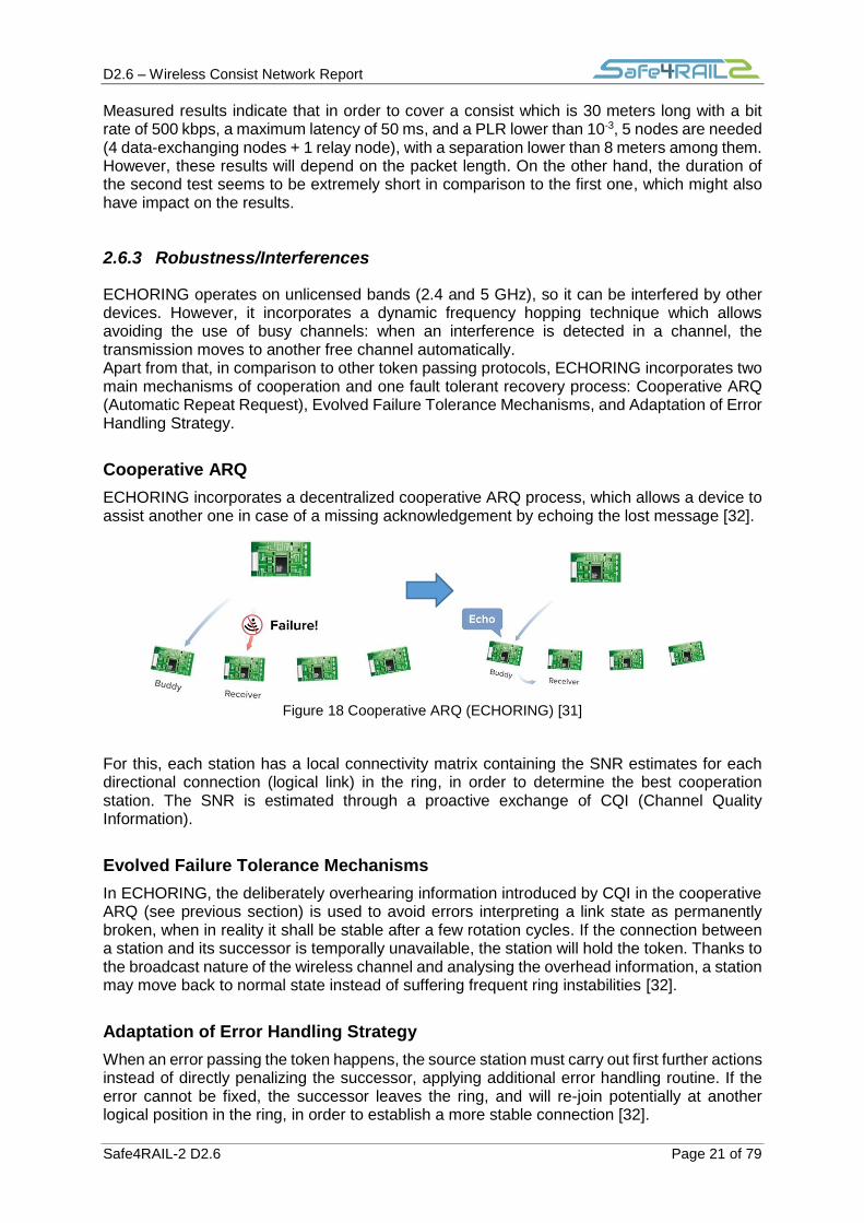
ECHORING incorporates a decentralized cooperative ARQ process, which allows a device to assist another one in case of a missing acknowledgement by echoing the lost message [32].
Figure 18 Cooperative ARQ (ECHORING) [31]
For this, each station has a local connectivity matrix containing the SNR estimates for each directional connection (logical link) in the ring, in order to determine the best cooperation station. The SNR is estimated through a proactive exchange of CQI (Channel Quality Information).
Evolved Failure Tolerance Mechanisms
In ECHORING, the deliberately overhearing information introduced by CQI in the cooperative ARQ (see previous section) is used to avoid errors interpreting a link state as permanently broken, when in reality it shall be stable after a few rotation cycles. If the connection between a station and its successor is temporally unavailable, the station will hold the token. Thanks to the broadcast nature of the wireless channel and analysing the overhead information, a station may move back to normal state instead of suffering frequent ring instabilities [32].
Adaptation of Error Handling Strategy
When an error passing the token happens, the source station must carry out first further actions instead of directly penalizing the successor, applying additional error handling routine. If the error cannot be fixed, the successor leaves the ring, and will re-join potentially at another logical position in the ring, in order to establish a more stable connection [32].

D2.6 – Wireless Consist Network Report
Safe4RAIL-2 D2.6 Page 22 of 79
In order to evaluate the three mechanisms explained earlier, in the following table a comparison can be seen between ECHORING and other token-ring technologies in terms of instability. These results indicate that ECHORING performs better than other technologies for small rings (i.e. lower PLR and lower instabilities).
Table 19 Comparison between ECHORING and other token-ring technologies [32]
2.6.4 Network Dimensions
Regarding network sizing, ECHORING supports 11 nodes as maximum and covers a distance of 30 m according to Table 16.
2.6.5 Additional considerations
Two risks exist about this technology: its lack of maturity (first prototype: November 2017), and the unavailability of multiple sources/vendors (proprietary technology by R3 Communications). Regarding technical performance, the results obtained for bit rate and latency indicate that the number of devices can be a limiting factor for this technology.
2.7 WISA (Wireless Interface for Sensors Actuators)
2.7.1 Bit rate
The bit rate of WISA is summarized in Table 20.
Operating Frequency 2.4 GHz
Bit Rate 1 Mbps (DL)
4x1 Mbps (UL)
Table 20 WISA Bit Rate [33]

D2.6 – Wireless Consist Network Report
Safe4RAIL-2 D2.6 Page 23 of 79
2.7.2 Time considerations
The latencies of WISA are summarized in Table 21.
Latency
Nominal (ms) 2
Typical (ms) 5
Worst-case (ms) 20
Density (slave / master) ≤120
Table 21 WISA latencies [33]
2.7.3 Robustness/Interferences
WISA uses frequency hopping mechanism, which is applied after superframe transmission with a carrier spacing of 1 MHz. It also provides blacklisting to exclude channels which exhibit large interference, to enable coexistence with other systems.
2.7.4 Network Dimensions
Regarding network sizing, WISA supports 120 users per cell and covers an estimated distance of 50,41 m. This communication distance has been calculated using typical transmitter power and receiver sensitivity values, and applying the intra-consist path loss model from [6].
Transmission Power (dBm) 0
Receiver Sensitivity (dBm) -85
Link Margin (dB) 85
Communication Distance (m) 50,41
Table 22 Network dimensions (WSAN/WISA)
2.7.5 Additional considerations
WISA is a proprietary technology from company ABB. On the other hand, the references found in literature about WISA go back to the late 2000s.

D2.6 – Wireless Consist Network Report
Safe4RAIL-2 D2.6 Page 24 of 79
Chapter 3 Future technologies
In this chapter several wireless technologies will be presented, which are either in development or in the research field, and which overcome some of the limitations of current wireless technologies for the WLCN. In this sense, SHARP, WirelessHP and Wi-Fi 6 improve the performance of current Wi-Fi solutions (especially SHARP and WirelessHP, in terms of deterministic medium access). On the other hand, LTE Releases 15/16 (5G) improve the latency values of current LTE solutions.
For these technologies, all details have been included in this chapter (not in annexes).
3.1 SHARP
SHARP (Synchronous and Hybrid Architecture for Real-time Performance) is a proprietary protocol developed by IKERLAN specially designed for industrial automation where Ultra-Reliable and Low Latency Communications (URLLC) are demanded. SHARP includes a physical layer based on IEEE 802.11g and a Time Division Multiple Access (TDMA) MAC layer on top of it (see Figure 19):
The PHY layer is a modification of IEEE 802.11g, maintaining compatibility with legacy standards.
Determinism and high reliability are guaranteed because of the MAC layer based on a TDMA scheme. In order to maintain determinism over Ethernet, SHARP makes use of the TSN (Time Sensitive Network) standard defined by IEEE Time-Sensitive Networking task group.
Figure 19 SHARP description
Network Topology
A tree topology is used in SHARP technology. This topology is formed by (see Figure 20):
1. A Network Control centre, which is normally a Programmable Logic Controller (PLC).
2. A wired TSN network.
3. SHARP Access Points (APs) connected to the TSN network.
4. Several nodes connected to each of the SHARP APs. These nodes can be Real-Time (RT) nodes (i.e. SHARP nodes), or conventional IEEE 802.11 nodes. Some nodes can also be directly connected to the wired segment of SHARP.

D2.6 – Wireless Consist Network Report
Safe4RAIL-2 D2.6 Page 25 of 79
Figure 20 SHARP topology [34]
MAC Layer
The TDMA Super-Frame used in SHARP is split into two periods (see Figure 21):
1. RT (Real Time) period: reserved to SHARP traffic (i.e. only SHARP traffic is allowed in this period).
2. Legacy period: used by IEEE 802.11 legacy stations to transmit non-RT traffic (i.e. only legacy IEEE 802.11 traffic is allowed during this period).
Figure 21 SHARP Super-Frame
This is the detailed structure of the SHARP superframe:
1. CTS (Clear-To-Send): a communication cycle always starts with a CTS frame, which is used to block the transmission of legacy nodes during the RT period. This is done by indicating the legacy nodes that the channel will be busy for a time equal to the duration of the RT period.
2. RT DL (Real-Time Downlink): the SHARP AP transmits frames to the slave nodes during the RT DL period. Once RT DL frame is transmitted, slave node must return an ACK if the reception has been correct.
3. DL RTX/CC (Downlink Retransmission / Control Channel): if the AP does not receive an ACK from all nodes in the RT DL period, it sends a retransmission RTX packet during the DL RTX/CC period until it receives all ACKs, or until the DL RTX/CC period is over.
4. RT UL (Real-Time Uplink): RT Packets from the slave nodes to SHARP AP are transmitted during RT UL period. As the slave nodes are only allowed to transmit in the time slots preassigned by the AP, there is no need of ACK in the UL period.

D2.6 – Wireless Consist Network Report
Safe4RAIL-2 D2.6 Page 26 of 79
5. UL RTX (Uplink Retransmission): similar to the DL RTX/CC period, if an RT frame from the RT UL period is lost, the AP must send at the start of UL RTX period an RTX frame to the slave nodes.
6. BE Period: when the Uplink retransmissions are finished (or when RT UL duration is over), the remaining time is used by IEEE 802.11 nodes to transmit legacy frames, ensuring compatibility with IEEE 802.11 standards. During this period, legacy nodes must gain access to the medium through CSMA/CA medium access scheme. In order to ensure that no legacy node invades the RT period and causes interferences, the BE period is divided into two parts:
a. NCP (Non Controlled Phase), where every IEEE 802.11 node is free to transmit
b. CP (Controlled Phase), where the AP takes control of the channel as soon as possible in order to prepare the RT period. In order to guarantee that the AP is able to take the channel, the maximum legacy frame size must be small enough. Two mechanisms are used for this:
i. Fix IEEE 802.11 basic rate configuration: the AP forces the nodes to use a minimum MCS (e.g. MCS = 2) to improve the network mean bitrate. This configuration reduces the maximum frame length.
ii. Fix Maximum Transmission Unit (MTU) size at link layer: MTU defines the maximum packet length in bytes that can be encapsulated into MAC frames. The MTU size configuration must be done manually in every legacy node.
PHY layer
SHARP’s PHY is based on IEEE 802.11g, which uses OFDM as modulation scheme because of its spectrum efficiency and robustness in time dispersive channels. SHARP is able to provide bit rate values up to 54 Mbps. In this sense, although IEEE 802.11ac provides higher bitrates by using MIMO and higher bandwidth, in applications where short frames are demanded (e.g. industrial applications) the frame rate is similar to IEEE 802.11g. Therefore, if no MIMO is used, the most efficient OFDM-based PHY for transmitting short packets is IEEE 802.11g.
However, the PHY layer of IEEE 802.11g presents inefficiencies when transmitting short packets, which increase transmission time. This is due to the length of the preamble and due to the zeros which are added in the last OFDM symbols [34]. In order to reduce the transmission time for short packets and increase the packet rate, two different waveforms have been defined in SHARP for DL and UL frames.
- DL Waveform: as can be observed in Figure 22, the frame structure of IEEE 802.11g PHY is formed by the fields Short Training Field (STF), Long Training Field (LTF), SIGNAL and Payload.
Figure 22 IEEE 802.11g DL waveform (3 frames)
The solution proposed in SHARP uses PHY frame aggregation (see Figure 23). A SHARP AP may send several DL packets in a row during DL period; therefore, an efficient way to transmit packets is joining together one preamble (i.e. LTF + STF), one SIGNAL and all the OFDM symbols generated in the modulation process of each payload. Thanks to this aggregation, transmission time is vastly reduced because the transmission only requires one preamble.

D2.6 – Wireless Consist Network Report
Safe4RAIL-2 D2.6 Page 27 of 79
Figure 23 SHARP DL waveform (3 subframes)
- UL Waveform:
Contrary to the DL waveform, where a long preamble is effective because of using the aggregation frame technique, in UL frames cannot be aggregated because frames are sent from different nodes to the AP. Therefore, the most efficient waveform is achieved using short packets. To do so, it is assumed that the channel remains invariant during all the communication cycle. The values present in [34] show that the channel variation over time in industrial environments is normally slower than the communication cycle (10-30 ms and 0.5 – 2 ms, respectively). The format of UL frames is shown in Figure 24.
Figure 24 UL waveform (SHARP)
Performance evaluation (OMNeT++ simulation)
In [34, 35], an evaluation of SHARP performance was done in OMNeT++ 5.0 simulator for uplink and downlink periods. The results provide information about MAC to MAC minimum and maximum delay of RT frames (deterministic traffic) (see Table 23). As it can be observed, there is a relation between the delay, number of nodes, and the modulation scheme (MCS: Modulation and Coding Scheme). Based on these results, it can be
confirmed that the maximum delay is less than 550 sec in all scenarios.
Channel UL UL UL DL DL DL
MCS 0 2 4 0 2 4
Number of nodes 11 15 20 11 15 20
Max Delay (s) 426 394 371 497 526 549
Min Delay (s) 26 22 18 26 22 18
Table 23 MAC to MAC delay (SHARP simulation)
Network Dimensions
Regarding network sizing, SHARP supports 20 users per cell and covers an estimated
distance of 216,49 m. This communication distance has been calculated using typical
transmitter power and receiver sensitivity values, and applying the intra-consist path loss
model from [6].
Transmission Power (dBm) 20
Receiver Sensitivity (dBm) -85
Link Margin (dB) 105
Communication Distance (m) 216,49
Table 24 Network dimensions (SHARP)

D2.6 – Wireless Consist Network Report
Safe4RAIL-2 D2.6 Page 28 of 79
3.2 LTE Release 15/16 (5G)
The release timeline for 5G, as specified by 3GPP, is depicted in Figure 25. 3GPP defined NR (New Radio) as the new technology for the fifth generation of mobile networks, with the following data rate values: 20Gb/s for DL (Downlink), and 10 Gb/s for UL (uplink).
Figure 25 5G timeline [36]
The ITU (International Telecommunication Union) has classified 5G services in three categories: URLLC (Ultra-Reliable Low Latency Communications), mMTC (massive machine-type communications) and eMBB (enhanced Mobile Broadband). Among these categories, the design of URLLC is the most challenging one because of the requirements of low latency and ultra-high reliability. Considering the fact that the current radio cannot support these services, 3GPP introduced NR in order to support them.
To address this situation, in the migration process to 5G, two modes of operation have been defined: NSA (Non standalone), where LTE is used for initial access and mobility handling, and SA (standalone), where the NR makes use of a new core and will be completely independent of the LTE core network [37].
NR 5G Technology
Figure 26 shows a KPI (Key Performance Indicator) comparison between current devices categories (see Section 2.1.1) and 5G NR-NSA [38]. These results show that the throughput could reach a bit rate more than 2 times the current values and latency could be reduced to the half.

D2.6 – Wireless Consist Network Report
Safe4RAIL-2 D2.6 Page 29 of 79
Figure 26 KPI summary 5G [38]
NR PHY layer overview
Waveform
NR adopts OFDM with CP as waveform for both Uplink and Downlink, while LTE only uses OFDM-CP for Downlink (see Chapter 9). On the other hand, NR supports different types of subcarrier spacing (LTE uses 15kHz), as shown in Table 25.
Subcarrier spacing (KHz) Slot duration Slots per subframe
15 1 ms 1
30 500 µs 2
60 250 µs 4
120 125 µs 8
240 62,5 µs 16
Table 25 NR subcarrier spacing
Frequency considerations
CA (Carrier Aggregation, see Chapter 9) tools are also developed to work in millimetre bands. These tools also support the possibility of having an NR carrier and an LTE carrier overlapping with each other in frequency, thereby enabling dynamic sharing of spectrum between NR and LTE. NR supports operation in two spectrum bands or Frequency Ranges (FR): FR1 from 450 MHz up to 6 GHz, and FR2 (or millimetre waves) from 24.5 GHz up to 52.6 GHz.
Bit Rate
In FR1, the maximum bit data rate for Downlink and Uplink are 578 Mbps and 620 Mbps, respectively [39].
D2.6 – Wireless Consist Network Report
Safe4RAIL-2 D2.6 Page 30 of 79
Frame structure and Duplexing modes
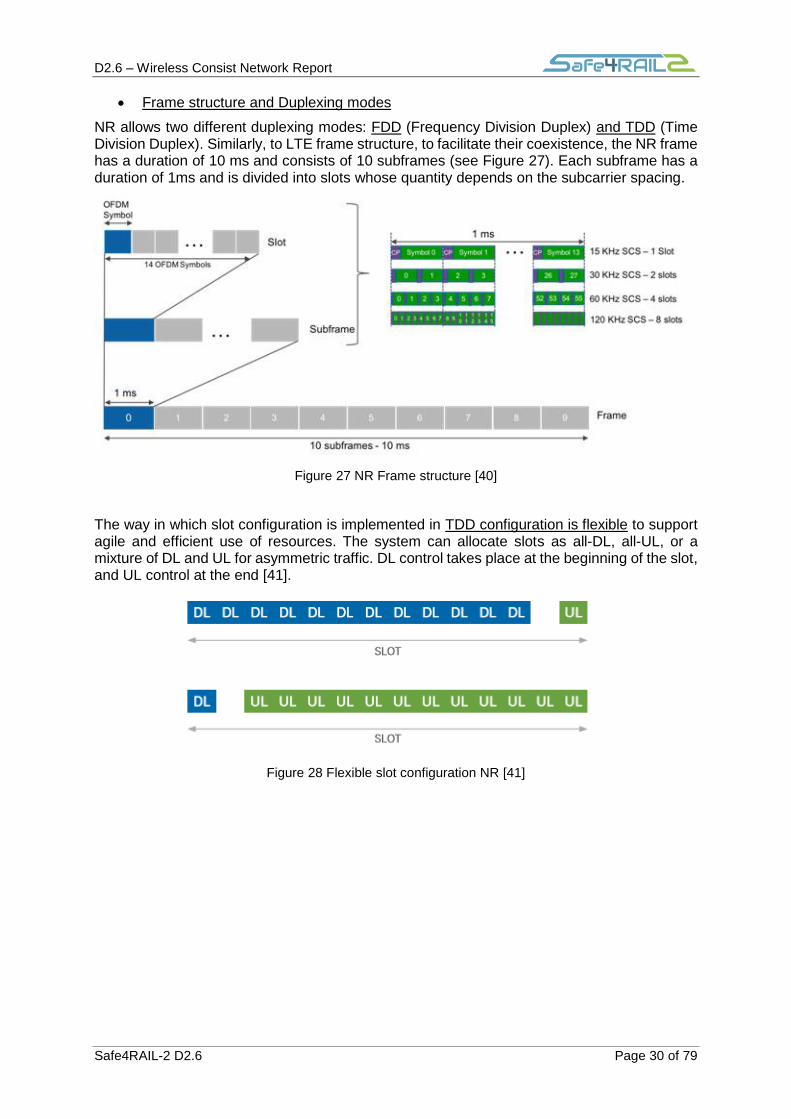
NR allows two different duplexing modes: FDD (Frequency Division Duplex) and TDD (Time Division Duplex). Similarly, to LTE frame structure, to facilitate their coexistence, the NR frame has a duration of 10 ms and consists of 10 subframes (see Figure 27). Each subframe has a duration of 1ms and is divided into slots whose quantity depends on the subcarrier spacing.
Figure 27 NR Frame structure [40]
The way in which slot configuration is implemented in TDD configuration is flexible to support agile and efficient use of resources. The system can allocate slots as all-DL, all-UL, or a mixture of DL and UL for asymmetric traffic. DL control takes place at the beginning of the slot, and UL control at the end [41].
Figure 28 Flexible slot configuration NR [41]

D2.6 – Wireless Consist Network Report
Safe4RAIL-2 D2.6 Page 31 of 79
Network Dimensions
Regarding network sizing, 5G supports 200 users per cell and covers an estimated
distance of 387,80 m. This communication distance has been calculated using typical
transmitter power and receiver sensitivity values, and applying the intra-consist path loss
model from [6].
Transmission Power (dBm) 23
Receiver Sensitivity (dBm) -90
Link Margin (dB) 113
Communication Distance (m) 387,80
3.3 WirelessHP
In the scope of the next industrial wireless technologies which will require extremely low
latency, ultra-high reliability and high data rates, ABB realized a PHY layer called WirelessHP
(High Performance), with the target of reducing the latency through the minimization of the
packet transmission time using short-packet communications (i.e. payloads shorter than 100
bits). The design of the WirelessHP PHY layer is based on the IEEE 802.11 standard,
modifying the PHY layer preamble and waveform (OFDM parameters) [42].
PHY layer:
Based on IEEE 802.11 PHY layer, WirelessHP uses OFDM as basic waveform, where the
preamble has a huge impact on the size of the entire packet. For instance, with a packet size
of 100 bits and a modulation order of 8 (M=8), 83% of the transmitted samples are used for
the preamble. In that sense, reducing the preamble implies a reduction of packet transmission
time. However, the customized preamble must support the main functions that the IEEE 802.11
original preamble offers, which are: packet detection and timing synchronization, frequency
offset estimation, channel estimation and information about length and coding. For that
purpose, some assumptions are done considering specific characteristics of industrial
environments, which are: predictability of traffic patterns, low temporal variability of the
industrial wireless channel, and the fact that the messages exchanged in industrial control
applications have a predefined length.
Apart from the overhead produced by the preamble, there are other three causes of overhead
which affect the efficiency of OFDM communications for short-packets, and therefore must be
taken into account:
1. Cyclic prefixes: which are contained in every data symbol.
2. Unused carriers: a set of subcarriers reserved for an especial use, like pilot subcarriers
for correcting residual phase errors, or guard subcarriers at the edges of the symbols.
3. Padding bits: the total number of subcarriers does not always coincide with the
information mapped, and therefore the exceeding subcarriers are padded with zeros
(Figure 29).

D2.6 – Wireless Consist Network Report
Safe4RAIL-2 D2.6 Page 32 of 79
Figure 29 OFDM overheads in data symbols for IEEE 802.11g (with 20 MHz bandwidth) and 802.11ac (160 MHz) [42].
The solution adopted by WirelessHP is a reduced preamble of 1 symbol and an optimal use of the OFDM parameters in order to minimize the total packet transmission time. Finding the optimal combination of the OFDM parameters results in a programming problem with specific constraints, which is widely developed in [42].
Network Topology:
A star topology is assumed as the most suitable one for developing this technology, with a controller at the centre of the network.
Performance of the WirelessHP PHY layer optimized in a simulation environment:
A performance evaluation was carried out assuming the following parameters in an industrial environments: L (packet size) of 100 bits (a representative value for critical control applications), low modulation orders (M=2, 4, 8) to achieve highly-reliable communications, and no MIMO to maintain a simple structure. On the other hand, OFDM parameters were selected to be as close as possible to IEEE 802.11 standard. In Figure 30, simulated packet transmission times are reported for different values of bandwidth and modulation orders, indicating that lower transmission times are obtained for higher modulation orders.
Figure 30 Simulated packet transmission time in WirelessHP [42].

D2.6 – Wireless Consist Network Report
Safe4RAIL-2 D2.6 Page 33 of 79
The efficiency with respect to the IEEE 802.11 standard is also increased according to Figure 31 and Figure 32, where the overhead reduction can be observed, which means less packet data time and less latency. In Figure 32 the modulation order is fixed to M=2. As an example, for a bit rate of 160 Mbps, IEEE 802.11 requires 6940 overhead samples, while WirelessHP needs only 371. As can be seen in Figure 31, a maximum bit rate of 480 Mbps is reached for
a packet transmission time of 1 sec.
Figure 31 Comparison between IEEE 802.11 and WirelessHP (L= 100bits) (Packet time vs Raw data rate) [42].
Figure 32 Comparison between IEEE 802.11 and WirelessHP (Number of samples) [42].
As a summary, it can be observed that WirelessHP is not a sufficiently mature technology, as only software implementations have been found in literature (i.e. Matlab implementations with USRP boards).
Network Dimensions
Regarding network sizing, WirelessHP covers a maximum distance of 25m according to the results from [42].

D2.6 – Wireless Consist Network Report
Safe4RAIL-2 D2.6 Page 34 of 79
3.4 Wi-Fi 6 (IEEE 802.11ax)
IEEE 802.11ax, also called High-Efficiency Wireless (HEW) and marketed as Wi-Fi 6, introduces significant changes on the PHY layer in comparison to its predecessors, maintaining at the same time backward compatibility. Developed by IEEE 802.11 Task Group, it is focused on offering mechanisms to support more clients in dense environments and provide a better experience in terms of throughput for typical wireless LAN networks. Based on IEEE 802.11ac, IEEE 802.11ax extends the Multi-User (MU) communications capabilities [25].
The main feature of IEEE 802.11ax is the adoption of OFDMA (Orthogonal Frequency Division Multiple Access) as modulation scheme. With OFDMA, subchannels are composed of groups of subcarriers called RUs (Resource Units). An AP (Access Point) can choose the best RU for each particular receiver, enabling parallel transmissions. Thanks to OFDMA, higher throughputs are provided with respect to the legacy DCF (see Section 2.5.2); in Figure 33 the improvement in terms of throughput is shown for 37 STAs (station) located at several distances from the AP.
OFDMA is similar to LTE (Long Term Evolution), as it uses Resource Units in a similar way as LTE uses Resource Blocks (see Figure 34); however, OFDMA in IEEE 802.11ax works on top of the legacy DCF (Distributed Coordination Function), which is similar to CSMA (see Section 2.5.2) and is coordinated by the AP. Hence, the AP dictates how many RUs are used within a 20 MHz channel and the different combinations that can be used. However, the rules of medium contention still apply, and the AP needs to compete for a transmission opportunity (TXOP). Once this opportunity is achieved, the AP is under control up to nine IEEE 802.11ax clients per either downlink or uplink transmission within a 20 MHz channel. The number of RUs used can vary in a per TXOP basis.
Figure 33 OFDMA gain in the overlapped network scenario [43]

D2.6 – Wireless Consist Network Report
Safe4RAIL-2 D2.6 Page 35 of 79
Figure 34 OFDM vs OFDMA [44]
PHY layer
New modulation techniques are introduced in IEEE 802.11ax. In addition to legacy BPSK (Binary Phase Shift Keying), 16-QAM (Quadrature Amplitude Modulation), 64-QAM and 256-QAM, there is the optional 1024-QAM. The number of subcarriers is augmented up to 256-tone OFDM and an increment in the OFDM symbol duration together with a longer Guard Interval (GI) is included, being more robust to propagation effects. Similarly to IEEE 802.11ac, a channelization of 160 MHz is supported in a continuous way (or 80+80 MHz in a non-continuous way). An 80+80 MHz channelization is combined from two non-adjacent 80 MHz channels. In Table 26 a comparison between IEEE 802.11ac (previous release) and IEEE 802.11ax is shown in terms of physical layer.
IEEE 802.11ac IEEE 802.11ax
Channel Bandwidth (MHz) 20,40,80,80+80,160 20,40,80,80+80,160
Subcarrier Spacing (KHz) 312,5 78,125
Symbol Time (µs) 3,2 12,8
Cyclic Prefix (µs) 0,8 – 0,4 0,8 – 1,6 – 3,2
MU-MIMO Downlink Uplink and Downlink
Modulation OFDM OFDM, OFDMA
Data Subcarrier Modulation BPSK, QPSK, 16-QAM, 64-QAM, 256-QAM
BPSK, QPSK, 16-QAM, 64-QAM, 256-QAM, 1024-QAM
Table 26 Comparison of IEEE 802.11ac, and IEEE 802.11ax [45].
PHY Format Frame
In order to support MU (Multiple User) transmissions, IEEE 802.11ax introduces the new PDDU (Packet Protocol Data Unit):
HE SU PPDU format (High Efficiency Single User): used when a single user is transmitting (Figure 35).
HE-MU (Multiple User): enables simultaneous transmission among MUs via OFDMA and/or MU-MIMO (Figure 36). The HE-SIG_B field is used to distinguish between single or multiple users.

D2.6 – Wireless Consist Network Report
Safe4RAIL-2 D2.6 Page 36 of 79
Figure 35 HE SU PPDU format [46]
Figure 36 HE-MU (Multiple User) format [46]
HE_EXT_SU (HE Extended Range PPDU): only for a single user, transmitted in 20 MHz channel bandwidths and with limited configurations, is intended for a user that may be further away from the AP, such as in outdoor scenarios. The HE-SIG-A field has a repetition of each symbol and a power-boosted preamble for reliable performance with longer coverage (Figure 37).
Figure 37 HE_EXT_SU format [46]
HE TB PPDU (HE Trigger-Based PPDU): users transmit simultaneously after receiving a trigger frame according to the resource allocation information. This PPDU format is identical to the HE SU PPDU format except that it uses a longer HE STF field in the HE preamble portion. Instead of using the HE-SIG-B field, the information required for the UL MU transmission from one or more STAs is carried by the trigger frame that initiates this transmission.
Figure 38 HE TB PPDU format [46]
BSS Coloring (Spatial Reuse)
In dense environments where plenty of IEEE 802.11 devices want to transmit at the same time and in the same channels, co-channel interferences are produced. As a consequence, IEEE 802.11 radios will defer transmissions if they hear the physical preamble of another BSS (Basic Service Set, see Chapter 13) trying to transmit in the same channel.
For example, in Figure 39, AP-1 desires to transmit in Channel 6; however, it detects the preamble of AP-2 in Channel 6, desiring to transmit as well, and AP-1 will defer its transmission in order to avoid collisions. This situation or issue is called OBSS (Overlapping Basic Service Set) interference or CCI (Co-Channel Interference). To increase the capacity in this type of dense environments, BSS coloring is introduced in IEEE 802.11ax. This mechanism implies a modification in the frame of IEEE 802.11ax; hence, only devices which use IEEE 802.11ax standard are able to interpret this technique (Figure 40).

D2.6 – Wireless Consist Network Report
Safe4RAIL-2 D2.6 Page 37 of 79
Figure 39 OBSS example
In this technique, when an IEEE 802.11ax radio listens the medium and hears a preamble, it checks the color bit of the transmitting radio. Depending on the color detected, the channel access method will be as follows:
1. If the detected color bit is the same as its own color (intra-BSS), then the transmission will be deferred.
2. If the detected color bit is different from its own color (inter-BSS), then the medium is considered as busy only during this period of detection.
Figure 40 BSS coloring
Depending on the BSS from which the traffic is generated, the receiving station can use different sensitive thresholds to transmit or defer. This means that it is possible to make use of adaptative clear channel assessment (CA), increasing the sensitivity threshold for inter-BSS frames and decreasing for intra-BSS. With this mechanism, BSS coloring can potentially decrease the channel contention problem.
Network Dimensions
Regarding network sizing, Wi-Fi 6 supports hundreds of users per cell and covers an estimated distance of 216,49 m. This communication distance has been calculated using typical transmitter power and receiver sensitivity values, and applying the intra-consist path loss model from [6] .

D2.6 – Wireless Consist Network Report
Safe4RAIL-2 D2.6 Page 38 of 79
Transmission Power (dBm) 20
Receiver Sensitivity (dBm) -85
Link Margin (dB) 105
Communication Distance (m) 216,49
Table 27 Network dimensions (Wi-Fi 6)
The Wi-Fi certified 6 certification program
Wi-Fi certified is defined as an international seal which approves a product (or a group of them) indicating that they have met industry-agreed standards for interoperability, security and a range of application specific protocols. In that sense, during the development process of the present report the Wi-Fi 6 certified program from Wi-Fi alliance was finalized. Therefore, the first Wi-Fi 6 certified products are the following (figures from September 16, 2019) [47]:
- Broadcom® BCM4375 - Broadcom® BCM43698 - Broadcom® BCM43684 - Cypress CYW 89650 Auto-Grade Wi-Fi 6 Certified - Intel® Wi-Fi 6 (Gig+) AX200 (for PCs) - Intel® Home Wi-Fi Chipset WAV600 Series (for routers and gateways) - Marvell 88W9064 (4x4) Wi-Fi 6 Dual-Band STA - Marvell 88W9064 (4x4) + 88W9068 (8x8) Wi-Fi 6 Concurrent Dual-Band AP - Qualcomm® Networking Pro 1200 Platform - Qualcomm® FastConnect 6800 Wi-Fi 6 Mobile Connectivity Subsystem - Ruckus R750 Wi-Fi 6 Access Point

D2.6 – Wireless Consist Network Report
Safe4RAIL-2 D2.6 Page 39 of 79
Chapter 4 Technology Summary
In order to define the most suitable technology for WLCN, in Table 28 and Table 29 a comparison is done between key requirements demanded by CONNECTA-2 for WLCN and the features offered by each technology. These tables are split in two parts, and must be interpreted as follows:
On the left side (grey background), key requirements are grouped in six sections:
1. Maximum Bit Rate and Maximum Latency depending on the type of WLCN
traffic.
2. Medium Access
3. Communication Range
4. Maximum number of nodes
5. Protection against interferences
6. TSN roadmap
On the right side, the parameters for each technology are specified. The parameters
which pass the requirements are marked in green, while those which don’t are marked
in red.
These key requirements have been obtained from the lower layer requirements of the WLCN. Overall, three categories have been defined for WLCN requirements, with the following colour code:
Lower Layer Requirements: requirements which are related with MAC and PHY layer.
Upper Layer Requirements: requirements which belong to upper layers (third layer and beyond)
Other Requirements: rest of requirements which cannot be classified in the others two categories.
For Table 28 and Table 29, a subset of the lower layer requirements has been used. For currently available wireless technologies, the results shown in these tables indicate that there is no single technology that covers all the requirements of the WLCN. The following analysis can be made on both current and future wireless technologies:
1. LTE provides a deterministic medium access and supports a wide range of data rate
requirements, although it only covers the traffic types which are under 100 Mbps. On
the other hand, it does not meet the low latencies of 4 ms and 8 ms required by Process
Data and Supervisory Data.
2. ZigBee and WirelessHART do not cover any of the bit rate requirements of the WLCN.
Regarding latencies, ZigBee covers all requirements except Process Data and
Supervisory Data, and WirelessHART presents a huge latency in comparison with the
rest of technologies and does not cover any of the latency requirements of the WLCN.
As a summary, neither ZigBee nor WirelessHART can be considered as suitable
wireless technologies for the WLCN.
3. UWB does not meet the high throughput values required by Process Data and Video
Streaming in the WLCN. On the other hand, it does not have a deterministic medium
access, and it is designed for short indoor coverage (room-coverage), as it is mainly
used in ranging applications. Therefore, it cannot be considered as an option for the
WLCN.
4. Wi-Fi is able to achieve the high data rates and low latencies required by all types of
traffic, but its medium access technique is non-deterministic.

D2.6 – Wireless Consist Network Report
Safe4RAIL-2 D2.6 Page 40 of 79
5. ECHORING provides low latency values, but only for small networks (i.e. 6-9 nodes),
and the obtained bit rates are only suitable for Audio Streaming applications. On the
other hand, the low number of nodes is a limiting factor for this technology.
6. WISA is a suitable technology in terms of deterministic medium access and low
latencies (only Time Sensitive Process Data cannot be covered). However, due to its
low data rate (1 Mbps) it is not applicable for the WLCN. On the other hand, only
outdated references have been found in literature.
7. SHARP presents extremely low latencies (below 1 ms) with a medium bit rate and a hybrid medium access (deterministic and non-deterministic). It presents also compatibility with IEEE 802.11g and TSN synchronization. However, the number of nodes is not enough for the WLCN.
8. 5G improves the features of its predecessor (LTE) by increasing the bit rate and covering all WLCN traffics, and reducing latencies down to 10 ms. This minimum latency value is theoretical and it should be checked against real implementations of 5G devices, especially to check the impact of the software dependency of the protocol.
9. WirelessHP presents optimal PHY features in terms of data rate, covering all traffic types required in the WLCN (except Video Streaming). However, the MAC layer has not been implemented yet, so it cannot be fully evaluated in terms of latency. On the other hand, only software implementations of WirelessHP have been found in literature.
10. Wi-Fi 6 provides very high data rates which cover the requirements of WLCN. No latency figures have been found in literature, but it is expected to overperform the low latencies provided by IEEE 802.11ac. However, the medium access layer is still non-deterministic.
Therefore, the following recommendations can be made for the WLCN:
1. ZigBee, WirelessHART and UWB are unsuitable technologies for the WLCN. WirelessHP cannot be used either, due to the lack of a MAC layer implementation.
2. ECHORING could be used for low-latency traffic, but WLCN data rate requirements should be relaxed. In addition, several ECHORING networks should be deployed to cover all nodes in the WLCN.
3. WISA could fit in the same category as ECHORING, but it should be further checked with ABB due to the lack of recent updates on this technology.
4. Wi-Fi could be used for non-critical and high-data-rate WLCN traffic, such as Audio/Video Data Streaming and Best Effort Data, as it is a high performance and non-deterministic technology. In order to use Wi-Fi for critical traffic, a deterministic MAC layer should be added, as has been done in SHARP.
5. LTE, in spite of providing a deterministic access, does not provide enough data rate for Streaming Data traffic, and it does not provide sufficiently low latency for Process Data and Supervisory Data traffic in the WLCN. 5G could be explored as an alternative, but further experimentation would be required to confirm the specified latency values.

D2.6 – Wireless Consist Network Report
Safe4RAIL-2 D2.6 Page 41 of 79
Table 28. Current wireless technologies for WLCN TECHNOLOGY FEATURES
ID Requirement WLCN REQUIREMENTS LTE ZigBee WirelessHART UWB
CTA2-NWK-03
CTA2-D1.1-18
CTA2-D1.1-28
CTA2-D1.1-29
Traffic Type Max Bit Rate Max Latency 50 Mbps (UL)
150 Mbps (DL) 50-300 ms 250 kbps
80 ms
(25-50 nodes) 250 kbps
15-60s
(50-100 nodes) 27 Mbps N/Ad
Process Data (Time Sensitive) 100 Mbps 4 ms N/Ad
Process Data (Normal) 100 Mbps 8 ms N/Ad
Message Data (Normal) 10 Mbps 250 ms N/Ad
Supervisory Data 10 Mbps 8 ms N/Ad
Streaming Data (Audio) 2 Mbps 100 ms N/Ad
Streaming Data (Video) 512 Mbps 100 ms N/Ad
Best Effort Data 10 Mbps Not Relevant - - - -
WLCN_WAP_23 Medium Access Deterministic Deterministic Non-Deterministic Deterministic Non-Deterministic
CTA2-GEN-03
WLCN_WAP_002
WLCN_WAP_003
WLCN_WED_002
WLCN_WED_003
Communication Range 30 m (1 car) 400 ma 100 ma 100 ma 20 ma
CTA2-D1.1-23
CTA2-D1.1-22
CTA2-D1.1-19
CTA2-D1.1-30
WLCN_WAP_21
Max. number of nodes 40 nodes / car 300/cell 65000 Hundreds N/Ad
CTA2-GEN-01
WLCN_WAP_22
Protection against
interferences -
Dedicated band +
MROc DSSS
DSSS +
Frequency Hopping
Wideband
Transmission
CTA2-D1.1-07
CTA2-D1.1-09
CTA2-COM-01
CTA2-D1.1-31
TSN Technology supports TSN
TSN in roadmap No No No No

D2.6 – Wireless Consist Network Report
Safe4RAIL-2 D2.6 Page 42 of 79
TECHNOLOGY FEATURES
ID Requirement WLCN REQUIREMENTS Wi-Fi ECHORING WSAN/WISA
CTA2-NWK-03
CTA2-D1.1-18
CTA2-D1.1-28
CTA2-D1.1-29
Traffic Type Max Bit Rate Max Latency 1.73 Gbps
1 – 20 ms
100 kbps (9 nodes)
1 Mbps (6 nodes)
5 Mbps (2 nodes)
1-10 ms
(6 – 9 nodes)
50-200 ms
(11 nodes)
4 x 1 Mbps (UL)
1 Mbps (DL)
5 ms
(typ)
Process Data (Time Sensitive) 100 Mbps 4 ms
Process Data (Normal) 100 Mbps 8 ms
Message Data (Normal) 10 Mbps 250 ms
Supervisory Data 10 Mbps 8 ms
Streaming Data (Audio) 2 Mbps 100 ms
Streaming Data (Video) 512 Mbps 100 ms
Best Effort Data 10 Mbps Not Relevant - - -
WLCN_WAP_23 Medium Access Deterministic Non-Deterministic Deterministic Deterministic
CTA2-GEN-03
WLCN_WAP_002
WLCN_WAP_003
WLCN_WED_002
WLCN_WED_003
Communication Range 30 m (1 car) 200 ma 30 mb 50 ma
CTA2-D1.1-23
CTA2-D1.1-22
CTA2-D1.1-19
CTA2-D1.1-30
WLCN_WAP_21
Max. number of nodes 40 nodes / car Hundreds 11
(Simulated) 120
CTA2-GEN-01
WLCN_WAP_22
Protection against
interferences - 802.11h: DFS (5 GHz)
Frequency Hopping +
Cooperative ARQ +
Evolved Failure Tolerance Mechanisms +
Adaptation of Error Handling Strategy
FDD + Frequency Hopping
CTA2-D1.1-07
CTA2-D1.1-09
CTA2-COM-01
CTA2-D1.1-31
TSN Technology supports TSN
TSN in roadmap No No No
a. Estimated from transmitter output power, receiver sensitivity, and intra-consist path loss model [6]
b. Measured value c. Mobility Robustness Optimization

D2.6 – Wireless Consist Network Report
Safe4RAIL-2 D2.6 Page 43 of 79
d. N/A: Not Available
Table 29 Future wireless technologies for WLCN
TECHNOLOGY FEATURES
ID Requirement WLCN REQUIREMENTS SHARP 5G WirelessHP Wi-Fi 6
CTA2-NWK-03
CTA2-D1.1-18
CTA2-D1.1-28
CTA2-D1.1-29
Traffic Type Max Bit Rate Max Latency 54 Mbps 550 sec 620 Mbps (UL)
578 Mbps (DL) 10-300 ms 480 Mbps
N/Ad 4.8 Gbps N/Ad
Process Data (Time Sensitive) 100 Mbps 4 ms N/Ad N/Ad
Process Data (Normal) 100 Mbps 8 ms N/Ad N/Ad
Message Data (Normal) 10 Mbps 250 ms N/Ad N/Ad
Supervisory Data 10 Mbps 8 ms N/Ad N/Ad
Streaming Data (Audio) 2 Mbps 100 ms N/Ad N/Ad
Streaming Data (Video) 512 Mbps 100 ms N/Ad N/Ad
Best Effort Data 10 Mbps Not Relevant - - - -
WLCN_WAP_23 Medium Access Deterministic Deterministic Deterministic N/Ad Non-Deterministic
CTA2-GEN-03
WLCN_WAP_002
WLCN_WAP_003
WLCN_WED_002
WLCN_WED_003
Communication Range 30 m (1 car) 200 ma 400 ma 25 me 200 ma
CTA2-D1.1-23
CTA2-D1.1-22
CTA2-D1.1-19
CTA2-D1.1-30
WLCN_WAP_21
Max. number of nodes 40 nodes / car 20 300/cell N/Ad N/Ad
CTA2-GEN-01
WLCN_WAP_22
Protection against
interferences - No
Dedicated Band +
MROc No BSS Coloring
CTA2-D1.1-07
CTA2-D1.1-09
CTA2-COM-01
CTA2-D1.1-31
TSN Technology supports TSN
TSN in roadmap Yes No No No
a Estimated from transmitter output power, receiver sensitivity, and intra-consist path loss model [6] b. Measured value
c. Mobility Robustness Optimization d. N/A: Not Available
e. Taken from [42]

D2.6 – Wireless Consist Network Report
Safe4RAIL-2 D2.6 Page 44 of 79
Chapter 5 Wireless TSN Demonstrator
In this chapter the Wireless TSN demonstrator done in Safe4RAIL-2 is described, which combines a SHARP deterministic wireless network from IKERLAN with a wired TSN endpoint from TTTech.
5.1 Architecture
Figure 41 shows the architecture of the Wireless TSN demonstrator. It consists of the following elements:
1. A wireless SHARP4 (w-SHARP) wireless network made of two STAs and one WAP.
2. A TSN wired network with three nodes:
a. The SHARP access point, which has a TSN IP by SoC-e for the wired part. This specific TSN IP was chosen due to its compatibility with IKERLAN’s Xilinx FPGA platforms.
b. A TSN switch with SoC-e’s TSN IP, based also on a Xilinx platform.
c. A TSN EndPoint (EP) consisting of a computer with TTTech’s TSN PCIe card.
Figure 41. Architecture of the Wireless TSN demonstrator
The key element of this architecture is the domain translator included in the SHARP Access Point. This domain translator features an Ethernet TSN interface and a w-SHARP interface, and its main task is to perform the transition from/to Ethernet TSN to/from w-SHARP. It has two main functions:
1. It acts as a boundary clock, extending the Ethernet TSN clock synchronization to the wireless domain.
2. It performs the traffic translation and routing between Ethernet TSN and w-SHARP.
In addition, the MAC of the w-SHARP protocol has been inspired by the 802.1Qbv standard and it enables TSN-like time windows synchronized to the network global time. Therefore, the w-SHARP and Ethernet TSN time windows can be easily time-synchronized, enabling the traffic translation between domains.
4 More details on SHARP technology can be found in Section 3.1

D2.6 – Wireless Consist Network Report
Safe4RAIL-2 D2.6 Page 45 of 79
5.2 TSN Configuration
The application built over the demonstrator is as follows. Every TSN cycle, the application senses a generic physical variable using an Analog-to-Digital Converter (ADC) built in the w-SHARP STA 1, which is sent to the Ethernet TSN EP. The Ethernet TSN EP generates a replica of that value that is sent to the w-SHARP STA 2. Finally, the application performs the corresponding actuation in the w-SHARP STA 2 through a Digital-to-Analog Converter (DAC), closing the control loop. In essence, the signal regenerated by the w-SHARP STA 2 is a delayed version of the one captured by the w-SHARP STA 1.
The TSN cycle Ts has been set to 500 µs. Two TSN flows have been considered to transport the application data through the Hybrid TSN network. The TSN Flow 1 transports the data from the w-SHARP STA 1 to the Ethernet TSN EP and the TSN Flow 2 performs the opposite operation.
TSN Flow 1 is as follows:
1. First, the ADC takes a sample at 120 µs. 2. The sample is sent through the w-SHARP network at 130 µs. 3. The w-SHARP frame is received at the domain translator, then it is translated, and sent
through the TSN interface at 200 µs. 4. Finally, the Ethernet TSN switch receives the TSN frame and delivers it to the Ethernet
TSN EP at 250 µs.
TSN Flow 2 is as follows:
1. The Ethernet TSN EP generates and sends a data frame to the Ethernet TSN switch at 400 µs.
2. The switch forwards the frame to the domain translator at 450 µs. 3. The domain translator receives the frame from the TSN interface, translates, and
forwards the frame to the w-SHARP interface. The w-SHARP interface sends the data at 500 µs.
4. Finally, the w-SHARP STA 2 receives the frame and places the data in the DAC interface, which converts the received data into an electrical signal at 630 µs.
This configuration provides an End-to-End (E2E) latency between the sensing to the actuation of 510 µs. The configuration of the Ethernet TSN and w-SHARP windows to meet the designed TSN flows is provided in Figure 42.
Figure 42. Configuration of the TSN windows in Ethernet TSN and w-SHARP
5.3 Measurement Results
Two types of tests have been done on this demonstrator: E2E latency measurements with Real-Time (RT) traffic, and throughput measurements of the Ethernet TSN and w-SHARP segments with Best Effort (BE) traffic. Figure 43 shows the platforms used to perform these tests, including their correspondence with the setup described in Figure 41.
RT DL
RT 2 BE 1
TSN Cycle n. Cycle n+1.
RT DL RT UL BE
Eth. TSN
w-SHARP
RT 1 BE 2 RT 2 BE 1 …
…0 130 200 500
450 150

D2.6 – Wireless Consist Network Report
Safe4RAIL-2 D2.6 Page 46 of 79
Figure 43. Safe4RAIL-2 Wireless TSN Demonstrator
5.3.1 RT Traffic E2E latency
This subsection presents the E2E latency evaluation along different segments of the network. The network has been programmed with the TSN flows described in Section 5.2. The latency has been measured in terms of mean value (µ) and jitter (σ). Table 30 summarizes the most relevant results obtained in these measurements. It can be observed that the latency provided by the network is in the range of 100 µs for both segments, which enables latency-demanding closed-loop control applications. It can also be observed that the domain translator is able to convert the frames between the domains with a guaranteed latency of less than 2 µs. Finally, the E2E latencies for TSN flow 1 and 2 equal 143.3 µs (63.1µs +0.7µs +79.5µs) and 202.9 µs (63.2µs + 1.3µs + 138.4µs) respectively. These results demonstrate that the implemented Hybrid TSN network can provide minimum and guaranteed latency.
TSN flow Source Destination Latency
µ [µs] 𝝈 [ns]
TSN flow 1
w-SHARP STA 1 w-SHARP AP
domain translator 63.1 18.4
w-SHARP AP domain translator
Eth. TSN. domain translator
0.7 0
Eth. TSN. domain translator
Eth. TSN EP 79.5 1030
TSN flow 2
Eth. TSN EP Eth. TSN.
domain translator 63.2 21.3
Eth. TSN. Domain translator w-SHARP AP domain translator 1.3 0
w-SHARP AP domain translator w-SHARP STA 2 138.4 17.3
Table 30. E2E latency of the RT traffic through the network
5.3.2 BE Throughput Capacity
A set of experiments have been performed to evaluate the BE throughput for TSN cycles of 500, 1000, and 2000 µs. First a 10 GByte file has been transferred between two Ethernet TSN devices; then, a 10 MByte file has been transferred from the w-SHARP AP to an STA. The results of these experiments for the three considered TSN cycles are summarized in Table 31.

D2.6 – Wireless Consist Network Report
Safe4RAIL-2 D2.6 Page 47 of 79
It can be noted that the BE throughput of each segment strongly depends on the configured TSN cycle. This result is expected since the BE throughput depends on the BE windows size, which is enlarged for larger TSN cycle durations. Also, we can highlight that the attainable traffic in Ethernet TSN is around three orders of magnitude higher than in the case of w-SHARP. This result is also expected because of the theoretical throughput of Ethernet TSN (1 Gbps) is much higher than w-SHARP (54 Mbps).
TSN Cycle [µs] Eth. TSN BE Throughput [Mbps]
w-SHARP BE Throughput [kbps]
500 µs 680 352
1000 µs 840 990
2000 µs 880 1320
Table 31. Ethernet TSN and w-SHARP BE throughput

D2.6 – Wireless Consist Network Report
Safe4RAIL-2 D2.6 Page 48 of 79
Chapter 6 Conclusions
In this deliverable a detailed survey of wireless technologies have been presented in order to analyze their suitability for a Wireless Consist Network (WLCN). This survey has concluded that some of these technologies could be suitable for specific types of traffics of the WLCN, but in order to cover all traffic types a combination of several wireless technologies would be needed. It has also been concluded that advanced wireless technologies such as the Ultra-Reliable and Low-Latency Communications (URLLC) services provided by 5G or deterministic extensions of the MAC layer of WiFi would be needed in order to meet the strict timing requirements of the WLCN. In order to prove this, one of these advanced technologies (SHARP) has been integrated in a wireless TSN demonstrator together with a wired TSN card from Safe4RAIL-2 WP1. This demonstrator has proven the interoperability between the TSN solutions of two providers, and has achieved bounded latencies for Real-Time traffic as low as 510 µs with six TSN hops including wired and wireless segments.

D2.6 – Wireless Consist Network Report
Safe4RAIL-2 D2.6 Page 49 of 79
Chapter 7 List of Abbreviations
Table 32 List of Abbreviations
Abbreviation Translation
3GPP 3rd Generation Partnership Project
5G Fifth generation cellular network technology
AODV Ad hoc On-Demand Distance Vector
AP Access Point
ARQ Automatic Repeat Request
AURLLC Ultra-Reliable and Low-Latency Communications
BB Base Band
BE Best Effort
BI Beacon Interval
B-IFDMA Block Interleaved FDMA
BPM Burst Position Modulation
BPSK Binary Phase Shift Keying
BSS Basic Service Set
CA Carrier Aggregation
CAP Contention Access Period
CC Component Carrier
CC Control Channel
CCI Co-Channel Interference
CFP Contention Free Period
CN Consist Network
CP Contention Period
CRS Cell Specific Signal
CS Consist Switch
CSAT Carrier Sensing Adaptative Transmission

D2.6 – Wireless Consist Network Report
Safe4RAIL-2 D2.6 Page 50 of 79
Abbreviation Translation
CTS Clear-To-Send
CW Contention Windows
DCF Distributed Coordination Function
DFS Dynamic Frequency Selection
DFT Discrete Fourier Transform
DIFS Distributed Inter-Frame Space
DL Downlink
DRS Discovery Reference Signal
DS Distribution System
DSSS Direct Sequence Spread Spectrum
ECN Ethernet Consist Network
EDCF Enhanced DCF
EP EndPoint
EPID Extended PAN ID
ESS Extended Service Set
FCC Federal Communications Commission
FDD Frequency Division Duplexing
FH Frequency Hopping
FR Frequency Ranges
GBR Guaranteed Bit Rate
GI Guard Interval
GSM Global System for Mobile communications
GTS Guaranteed Timeslots
HCCA Hybrid Coordination Function Controlled Access
HEW High-Efficiency Wireless
IEEE Institute of Electrical and Electronics Engineers
IP Internet Protocol

D2.6 – Wireless Consist Network Report
Safe4RAIL-2 D2.6 Page 51 of 79
Abbreviation Translation
ISI Inter-Symbol-Interference
ISM Industrial, Scientific and Medical Radio Bands
ITU International Telecommunication Union
KPI Key Performance Indicator
LAA License Assisted Access
LAN Local Area Networks
LBT Listen Before Talk
LTE Long Term Evolution
LTE-U Unlicensed LTE
LTF Long Training field
LWA LTE Wi-Fi Aggregation
MAC Medium Access Control
MCS Modulation and Coding Scheme
MLB Mobility Load Balancing
mMTC Massive Machine-Type Communications
MRO Mobility Robustness Optimization
MTU Maximum Transmission Unit
MUI Multi-user interference
MU-MIMO Multi-user Multiple-Input-Multiple-Output
N/A Not Available
NB Narrow Band
NHN Neutral Host Network
Non-GBR Non-Guaranteed Bit Rate
NR New Radio
NSA Non standalone
OBSS Overlapping Basic Service Set
OFDM Orthogonal Frequency Division Multiple

D2.6 – Wireless Consist Network Report
Safe4RAIL-2 D2.6 Page 52 of 79
Abbreviation Translation
OFDMA Orthogonal Frequency Division Multiple Access
OFDMA-CP Cyclic-Prefix Orthogonal Frequency Division Multiplexing
OSI Open System Interconnection
PA Power Amplifier
PAN Personal Area Networks
PAPR Peak Average Power Ratio
PCF Point Coordination Function
PDDU Packet Protocol Data Unit
PDSCH Physical Downlink Shared Channel
PHY Physical
PLMN Public Land Mobile Network
PLR Packet Loss Rate
PSS Primary Synchronization Signal
P TX Transmission Power
PURLLC Periodic URLLC
QAM Quadrature Amplitude Modulation
QCI QoS Class identifier
RFC Request for Comments
RLF Radio Link Failure
RSSI Received Signal Strength Indicator
RT Real Time
RTX Retransmission
RU Resource Unit
SA Standalone
SC Secondary Cell
SC-FDMA Single Carrier Frequency Division Multiple Access
SFD Start of Frame Delimiter

D2.6 – Wireless Consist Network Report
Safe4RAIL-2 D2.6 Page 53 of 79
Abbreviation Translation
SHARP Synchronous and Hybrid Architecture for Real-time Performance
SHR Synchronization Header
SNR Signal Noise Ratio
SO macSuperframeOrder
SON Self-Optimisation Network
SS Spread Spectrum
SSS Secondary Synchronization Signal
STA Station
STF Short Training Field
SU-MIMO Single-user Multiple-Input-Multiple-Output
TDD Time Division Duplexing
TDMA Time Division Multiple Access
THT token holding time
TPC Transmit Power Control
TSMP Time Synchronized Mesh Protocol
TSN Time Sensitive Network
TXOP Transmission Opportunity
UE User Equipment
UL Uplink
UMTS Universal Mobile Telecommunications System
URLLC Ultra-Reliable and Low Latency Communications
USIM Universal Subscriber Identity Module
USRP Universal Software Radio Peripheral
UWB Ultra-Wide Band
WAP Wireless Access Point
WDIO Wireless Devices I/O module
WED-S Safe Wireless End Device

D2.6 – Wireless Consist Network Report
Safe4RAIL-2 D2.6 Page 54 of 79
Abbreviation Translation
WISA Wireless Interface for Sensors Actuators
WLCN Wireless Consist Network
WMN Wireless Mesh Networking
WSAN Wireless Sensor and Actor Networks
WSIX Wireless Sensor Interface for proximity services
WSP Wireless Sensor Pad

D2.6 – Wireless Consist Network Report
Safe4RAIL-2 D2.6 Page 55 of 79
Chapter 8 References
1. ETSI. LTE; Evolved Universal Terrestrial Radio Access (E-UTRA); User Equipment (UE) radio access capabilities (3GPP TS 36.306 version 14.2.0 Release 14). Available from: https://www.etsi.org/deliver/etsi_ts/136300_136399/136306/14.02.00_60/ts_136306v140200p.pdf.
2. 3GPP. Digital cellular telecommunications system (Phase 2+) (GSM); Universal Mobile Telecommunications System (UMTS); LTE; Policy and charging control architecture (3GPP TS 23.203 version 14.6.0 Release 14). Available from: https://www.etsi.org/deliver/etsi_ts/123200_123299/123203/14.06.00_60/ts_123203v140600p.pdf.
3. Tektronix. LTE Networks: Evolution and Technology Overview. Available from: http://commsforce.com.au/_literature_97479/LTE_Networks_Whitepaper_-_Evolution_and_Technology_Overview.
4. 3GGP. Self-Organizing Networks. Available from: https://www.3gpp.org/technologies/keywords-acronyms/105-son.
5. ETSI. LTE; Requirements for further advancements for Evolved Universal Terrestrial Radio Access (E-UTRA) (LTE-Advanced) (3GPP TR 36.913 version 10.0.0 Release 10). Available from: https://www.etsi.org/deliver/etsi_tr/136900_136999/136913/10.00.00_60/tr_136913v100000p.pdf.
6. Roll2Rail, D2.2 - Characterisation of the Railway Environment for Radio Transmission. 2016.
7. Fujitsu. High-Capacity Indoor Wireless Solutions: Picocell or Femtocell? ; Available from: https://www.fujitsu.com/us/Images/High-Capacity-Indoor-Wireless.pdf.
8. Dakuri Chiranjeevi, B.R., M Devender, B Kira. Performance Evaluation of Lte Femtocell in an Indoor Cellular Network. Available from: http://www.iraj.in/journal/journal_file/journal_pdf/1-109-142286778620-23.pdf.
9. Fujitsu. FUJITSU Network BroadOne LTE Femtocell Product Lineup. Available from: https://www.fujitsu.com/global/products/network/products/femto-spec/index.html.
10. Flore, D. 3GPP & unlicensed spectrum. 2015; Available from: https://www.3gpp.org/ftp/Information/presentations/presentations_2015/2015_01_3GPP_unlicensed_Dino_Flore.pdf.
11. Qualcomm. MulteFire Technology Progress and Benefits, and How It Enables A New Breed of Neutral Hosts Available from: https://www.qualcomm.com/media/documents/files/multefire-technology.pdf.
12. Mina Labib, V.M., Jeffrey H. Reed, Amir I. Zaghlou. Extending LTE into the Unlicensed Spectrum: Technical Analysis of the Proposed Variants. 2017; Available from: https://arxiv.org/pdf/1709.04458.pdf.
13. Keysight-Technologies. 4G LTE-A in Unlicensed Band – Use Cases and Test Implications. Available from: http://literature.cdn.keysight.com/litweb/pdf/5992-2705EN.pdf.
14. INTEL. Alternative LTE Solutions in Unlicensed Spectrum: Overview of LWA, LTE-LAA and Beyond. Available from: https://www.intel.com/content/dam/www/public/us/en/documents/white-papers/unlicensed-lte-paper.pdf.

D2.6 – Wireless Consist Network Report
Safe4RAIL-2 D2.6 Page 56 of 79
15. Silicon-Labs. AN1138: Zigbee Mesh Network Performance. Available from: https://www.silabs.com/documents/login/application-notes/an1138-zigbee-mesh-network-performance.pdf.
16. M.S. Costa, J.L.M.A. Analysis of wireless industrial automation standards: ISA-100.11a and WirelessHART. Available from: https://www.isa.org/standards-publications/isa-publications/intech-magazine/2012/december/web-exclusive-analysis-wireless-industrial-automation-standards-isa-100-11a-wirelesshart/.
17. Siemens. Wireless HART Siemens - Innovative Technology and Products for Process Industry. Available from: https://w5.siemens.com/web/at/de/industry/ia_dt/aktuelles/veranstaltungen/wireless-days2011/Documents/02_WirelessHART_ProductPresentation_en.pdf.
18. Stig Petersen, S.C. Performance Evaluation of WirelessHART for Factory Automation. Available from: https://people.eecs.berkeley.edu/~pister/290Q/Papers/HART/Petersen%20WirelessHART.PDF.
19. Phoenix-Contact. Wireless Hart solutions Available from: http://www.phoenixcontact.net/microsites/wireless-hart/895.htm.
20. E. Karapistoli, F.-N.P. An Overview of the IEEE 802.15.4a Standard. Available from: http://newton.ee.auth.gr/pavlidou/papers/J075.pdf.
21. BLUFLUX. What Happened to Ultra-Wideband (UWB) Technology? ; Available from: https://www.bluflux.com/what-happened-to-ultra-wideband-uwb-technology/.
22. informIT. Introduction to Ultra-Wideband Communications. Available from: http://www.informit.com/articles/article.aspx?p=433381&seqNum=5.
23. Yang, O. Introduction to Ultra Wideband (UWB). Available from: http://www2.ece.rochester.edu/projects/wcng/meetings/YangSp07.
24. INTEL. IEEE 802.11 Wi-Fi protocol summary. Available from: https://www.intel.com/content/www/us/en/support/articles/000005725/network-and-i-o/wireless-networking.html#legacy.
25. CISCO. IEEE 802.11ax: The Sixth Generation of Wi-Fi. Available from: https://www.cisco.com/c/dam/en/us/products/collateral/wireless/white-paper-c11-740788.pdf.
26. IEEE. IEEE Standard for Information technology. Telecommunications and information exchange between systems. Local and metropolitan area networks. Specific requirements. Part 11: Wireless LAN Medium Access Control(MAC) and Physical Layer (PHY) Specifications. Available from: http://www.di-srv.unisa.it/~vitsca/RC-0809I/IEEE-802-11.pdf.
27. António Grilo, M.N. PERFORMANCE EVALUATION OF IEEE 802.11E Available from: http://www.ee.sunysb.edu/~xwang/public/readings/grilo02performance.pdf.
28. Dave Cavalcanti, M.R., Laurent Cariou, Ganesh Venkatesan, Robert Stacey. Controlling latency in 802.11. Available from: https://mentor.ieee.org/802.11/dcn/18/11-18-1160-00-0wng-controlling-latency-in-802-11.pptx.
29. Xiaolin Jiang, H.S.-G., Gabor Fodor, Eytan Modiano, Zhibo Pang,Michele Zorzi, Carlo Fischione, Low-Latency Networking: Where Latency Lurks and How to Tame It. Proceedings of the IEEE. 107(2).
30. Choi, D.Q.S. IEEE 802.11h: Technology and Application. Available from: https://pdfs.semanticscholar.org/50fb/591f6027f5e381c3774b0235ff2c1f64ca5e.pdf.

D2.6 – Wireless Consist Network Report
Safe4RAIL-2 D2.6 Page 57 of 79
31. ECHORING. ECHORING website, by R3 communications. Available from: https://echoring.com/.
32. Christian Dombrowski, J.G. EchoRing: A Low-Latency, Reliable Token-Passing MAC Protocol for Wireless Industrial Networks. Available from: http://www.jamesgross.org/wp-content/uploads/2016/01/CRV_EchoRing.pdf.
33. Richard Steigmann, A.S.-K.G., Germany Jan Endresen, ABB Corporate Research, Norway Introduction to WISA - White Paper - Wireless Interface for Sensors and Actuators 2006; Available from: http://www.millennialnet.com/MillennialNet/media/Resources_Media/WhitePapers/WhitePaper_IntroductiontoWISA_V2.pdf.
34. Óscar Seijo, Z.F., Iñaki Val, Jesús A. López-Fernández, SHARP: Towards the Integration of Time-Sensitive Communications in Legacy LAN/WLAN, in IEEE Globecom Workshops. 2018: Abu Dhabi, United Arab Emirates.
35. Óscar Seijo, Z.F., Iñaki Val, Jesús A. López-Fernández SHARP: A novel hybrid architecture for industrial wireless sensor and actuator networks in 14th IEEE International Workshop on Factory Communication Systems (WFCS) 2018: Imperia, Italy.
36. Qualcomm. Making 5G NR a reality. Available from: https://www.qualcomm.com/media/documents/files/whitepaper-making-5g-nr-a-reality.pdf.
37. Hyoungju Ji, S.P., Jeongho Yeo, Younsun Kim, Juho Lee, and Byonghyo Shim Ultra-Reliable and Low-Latency Communications in 5G Downlink: Physical Layer Aspects.
38. Qualcomm. Predicting real-world performance of 5G NR mobile networks and devices Available from: https://www.qualcomm.com/news/onq/2018/03/07/predicting-real-world-5g-performance.
39. Rohde&Schwarz. 3GPP categories and data rates up to Release 15. Available from: https://www.mobilewirelesstesting.com/wp-content/uploads/2018/11/3GPP_categories_and_data_rates_up_to_Rel_15_po_en_folded_5216-3943-82_v0100.pdf.
40. ElectronicsMaker. 5G New Radio: The Next Step in Mobile Communications. Available from: https://electronicsmaker.com/5g-new-radio-the-next-step-in-mobile-communications.
41. National-Instruments. 5G New Radio: Introduction to the Physical Layer. Available from: http://www.digitimes.com.tw/seminar/ni_20180627/5G.pdf.
42. Michele Luvisotto, Z.P., Dacfey Dzung,Ming Zhan,Xiaolin Jiang, Physical Layer Design of High Performance Wireless Transmission for Critical Control Applications. IEEE Transactions on Industrial Informatics, 2017. 13(6): p. 2844-2854.
43. Evgeny Khorov, A.K., Andrey Lyakhov, Giuseppe Bianchiz, A Tutorial on IEEE 802.11ax High Efficiency WLANs. IEEE Communications Surveys & Tutorials, 2019. 21(1): p. 197-216.
44. National-Instruments. Introduction to 802.11ax High-Efficiency Wireless. Available from: http://www.ni.com/es-es/innovations/white-papers/16/introduction-to-802-11ax-high-efficiency-wireless.html.
45. Rohde&Schwarz. IEEE 802.11ax Technology Introduction White Paper. Available from: https://scdn.rohde-schwarz.com/ur/pws/dl_downloads/dl_application/application_notes/1ma222/1MA222_1e_IEEE80211ax.pdf.
46. Der-Jiunn Deng, Y.-P.L., Xun Yang, Jun Zhu, Yun-Bo Li, Jun Luo, and Kwang-Cheng Chen, IEEE 802.11ax: Highly Efficient WLANs for Intelligent Information Infrastructure.

D2.6 – Wireless Consist Network Report
Safe4RAIL-2 D2.6 Page 58 of 79
47. WiFi-Alliance. Wi-Fi CERTIFIED 6™ delivers new Wi-Fi® era Available from: https://www.wi-fi.org/news-events/newsroom/wi-fi-certified-6-delivers-new-wi-fi-era.
48. Qualcomm. Understanding 3GPP – starting with the basics Available from: https://www.qualcomm.com/news/onq/2017/08/02/understanding-3gpp-starting-basics.
49. Qualcomm. INTRODUCTION TO SINGLE CARRIER FDMA. Available from: https://www.eurasip.org/Proceedings/Eusipco/Eusipco2007/Papers/d3l-a01.pdf.
50. OFDM and SC-FDMA. Available from: https://blog.3g4g.co.uk/2009/02/ofdm-and-sc-fdma.html.
51. Agilent-Technologies. 3GPP Long Term Evolution: System Overview, Product Development, and Test Challenges. Available from: https://literature.cdn.keysight.com/litweb/pdf/5989-8139EN.pdf?id=1431418.
52. ShareTechnote. LTE TDD Overview Available from: https://www.sharetechnote.com/html/LTE_TDD_Overview.html.
53. Symmetry-Electronics. LTE EVOLUTION. Available from: https://www.semiconductorstore.com/blog/2018/From-Digi-How-to-Pick-the-Right-4G-LTE-Technology-for-Your-Business-Needs-and-Applications/3442/.
54. Qorvo. Carrier Aggregation - What’s New in Mobile CA? . Available from: https://www.qorvo.com/resources/d/qorvo-carrier-aggregation-brochure.
55. Tabbane, S. Session 5: NB-IoT Networks ITU Asia-Pacific Centre of Excellence Training On Traffic engineering and advanced wireless network planning. Available from: https://www.itu.int/en/ITU-D/Regional-Presence/AsiaPacific/SiteAssets/Pages/ITU-ASP-CoE-Training-on-/Session5_NB_IoT%20networks%20web.pdf.
56. Keysight-Technologies, LPWAN Technologies. Feb 2019.
57. Hillman, M. An Overview of ZigBee Networks; A ghuide for implementers and security testers. Available from: https://www.mwrinfosecurity.com/assets/Whitepapers/mwri-zigbee-overview-finalv2.pdf.
58. ZigBee / IEEE 802.15.4. Available from: https://fenix.tecnico.ulisboa.pt/downloadFile/3779579626799/Zigbee-sintese.pdf.
59. Adil Sheraz, W.U.K., Javed Iqbal Bangash, Syed Irfan Ullah, Abdus Salam, Abdul Waheed Khan, Sheeraz Ahmed. Impact of Beacon Order and Superframe Order on IEEE 802.15.4 for Nodes Association in WBAN. Available from: https://pdfs.semanticscholar.org/3b05/ba9ccede7fcdc3da40b1d2fbf2772429be7f.pdf?_ga=2.225634458.1401276536.1577974294-1312875266.1529587849.
60. Francesco, M.D. The IEEE 802.15.4 Standard and the ZigBee Specifications. Available from: http://www.cse.tkk.fi/fi/opinnot/T-110.5111/2014/luennot-files/ieee-802.15.4-zigbee.pdf.
61. Dung Nguyen, P.H.P. A Reliable and Efficient Wireless Sensor Network System for Water Quality Monitoring. Available from: https://ecommons.udayton.edu/cgi/viewcontent.cgi?article=1135&context=cps_fac_pub.
62. Assured-Systems. What is a ZigBee Network? A Concise Overview. Available from: https://www.assured-systems.com/uk/news/article/what-is-a-zigbee-network/.
63. FCC. FIRST REPORT AND ORDER ; Before the Federal Communications Commission Washington, D.C. 20554. Available from: https://transition.fcc.gov/Bureaus/Engineering_Technology/Orders/2002/fcc02048.pdf.

D2.6 – Wireless Consist Network Report
Safe4RAIL-2 D2.6 Page 59 of 79
64. Alberts, M. ANALYSIS OF THE IEEE 802.15.4A ULTRA WIDEBAND PHYSICAL LAYER THROUGH WIRELESS SENSOR NETWORK SIMULATIONS IN OMNET++. Available from: https://pdfs.semanticscholar.org/70a3/47d93960f103cbd59c9646a8c3f5b20865c6.pdf.
65. Ville Niemelä, M.H., Jari Iinatti. Improved Usage of Time Slots of the IEEE 802.15.4a UWB System Model Available from: http://www.ee.oulu.fi/~mattih/WPMC2011_FEELIT.pdf.
66. Rabbit. An Introduction to Wi-Fi (Product Manual). Available from: http://ftp1.digi.com/support/documentation/0190170_b.pdf.
67. Réussir-son-CCNA. Architecture WiFi. Available from: https://reussirsonccna.fr/architecture-wifi/.
68. Aqsa Malik, J.Q., Basharat Ahmad, Kok-Lim Alvin Yau, Ubaid Ullah. QoS in IEEE 802.11-based Wireless Networks: A Contemporary Survey 2014; Available from: https://arxiv.org/abs/1411.2852.
69. Delphine Christin, P.S.M., Matthias Hollick. Survey on Wireless Sensor Network Technologies for Industrial Automation: The Security and Quality of Service Perspectives. Available from: https://www.mdpi.com/1999-5903/2/2/96/pdf.
70. Thomas Gallenkamp, E.E., Stephan Pfletschinger, Stephan Sand, Paul Unterhuber, Christophe Gransart, Marion Berbineau, Iñaki Val, Aitor Arriola, Cyril Adrian, Martin Mayr, Luis Mesa, D2.3 – State of the Art in Radio Technologies and Recommendation of Suitable Technologies.

D2.6 – Wireless Consist Network Report
Safe4RAIL-2 D2.6 Page 60 of 79
Chapter 9 Annex LTE
LTE (Long-term evolution) is the evolution of UMTS (Universal Mobile Telecommunication System) and is developed and maintained by the 3GPP (the Third Generation Partnership Project). The first release of LTE (Release 8) was done in December 2008, and it is considered as the basis for the following releases. The release timeline is detailed in Figure 44.
Figure 44 LTE releases [48]
The main features of LTE technology can be summarized as follows:
LTE is based on SC-FDMA (Single Carrier Frequency Division Multiple Access) scheme for Uplink, and OFDMA-CP (Cyclic-Prefix Orthogonal Frequency Division Multiplexing) for Downlink [49] (see Figure 45):
- OFDMA: it is a multicarrier modulation technique that uses orthogonal subcarriers to convey information. The bandwidth of a subcarrier is designed to be smaller than the coherence bandwidth of the channel, so that each subchannel sees a flat fading channel, reducing equalizer complexity in the receiver and making it an attractive option for downlink transmission. Furthermore, by splitting a high-rate data stream in lower-rate streams transmitted in parallel, the ISI (Inter-Symbol-Interference) is minimised. However, OFDM has the following disadvantages: high sensitivity to frequency offset, a need for data coding schemes to overcome loss of data due to spectral nulls in the channel (flat fading), and high peak-to-average power ratio (PAPR). The high PAPR is due to the fact that several subcarriers are summed up in OFDMA. As each subcarrier has a different phase, the peak value of the signal can be very large in comparison to the average signal. On the other hand, in order to avoid inter symbol interference (ISI), in OFDMA-CP the last part of the OFDM symbol is appended at the start of the OFDM symbol as a guard interval called Cyclic Prefix (CP). The length of this CP must be larger than the delay spread of the channel.
- SC-FDMA: it can be considered as an OFDMA modulation where time-domain data symbols are transformed to frequency domain by DFT before going through OFDMA modulation. The use of a single-carrier modulation in the uplink is due to the lower peak-to-average ratio of the transmitted signal (i.e. PAPR is inherently low compared to OFDM), increasing the battery life of the devices and simplifying the design of power amplifiers. On the other hand, the equalization required to correct the distortion of a single-carrier signal due to frequency-selective fading is not an issue in the uplink as there are fewer restrictions in signal-processing resources at the base station compared to the mobile terminal.

D2.6 – Wireless Consist Network Report
Safe4RAIL-2 D2.6 Page 61 of 79
Figure 45. OFDMA and SC-FDMA [50]
LTE has two different full duplex modes: FDD (Frequency Division Duplexing) and TDD (Time Division Duplexing). Frame structure Type 1 is defined for FDD, and frame structure Type 2 is defined for TDD:
- Frame structure Type 1 (FDD): DL and UL operate in different frequencies (full duplex). Each radio frame is 10 ms long and consists of 10 subframes. Each subframe is formed by two slots, and uplink and downlink have the same frame structure (Figure 46).
Figure 46 LTE frame structure Type 1 (FDD) [51]
- Frame structure Type 2 (TDD): each radio frame is 10 ms long. The frame consists of two "half-frames" of equal length, with each half-frame consisting of either 10 slots or 8 slots. Each slot is 0.5 ms in length and two consecutive slots form exactly one subframe (see Figure 47). The allocation of the uplink-downlink subframes depends on the frame configuration (see Figure 48).

D2.6 – Wireless Consist Network Report
Safe4RAIL-2 D2.6 Page 62 of 79
Figure 47 LTE frame structure Type 2 (TDD) [51]
Figure 48 Frame configuration [52]
LTE is spectrally efficient thanks to a scalable bandwidth between 1.4 and 20 MHz (Release 8). Besides, from Release 10 (LTE Advanced) and beyond, the concept of CA (Carrier Aggregation) was defined for both FDD and TDD. This is a technique used to combine multiple LTE signals called Component Carriers (CC) across the available spectrum in order to support wider bandwidth and increase data rates. Each CC can have a bandwidth of 1.4, 3, 5, 10, 15 or 20 MHz, and initially a maximum of five CC components can be combined, hence obtaining a maximum aggregated bandwidth of 100 MHz (Figure 49). From LTE Release 10 (LTE- A) onwards, the number of maximum CCs that can be combined is reaching higher values, therefore increasing data throughput, as shown in Figure 50 for LTE-A Pro, which allows up to 32 CC.

D2.6 – Wireless Consist Network Report
Safe4RAIL-2 D2.6 Page 63 of 79
Figure 49 CA data pipe LTE [53]
Figure 50 CA timeline [54]
LTE supports SU-MIMO (single-user multiple input/multiple output) and MU-MIMO (multiple-user multiple input/multiple output) antenna configurations. MIMO systems utilizes multiple antennas in order to send and receive multiple data streams at once. MIMO makes use of multipath fading. Due to a coherent combination of the multiple signal received, the SNR (Signal Noise Ratio) is enhanced, increasing bit rate.
9.1 LTE – M and NB-IoT
In the scope of the Internet of things (IoT), LTE introduced in Release 13 new specifications related to low power wide area (LPWA) networks in licensed spectrum, with the following features:
1. Low power consumption, which implies devices operating for many years on a single charge.
2. Low device cost.
3. Improved indoor and outdoor coverage compared with existing wide area technologies.
4. Optimised data transfer for small, intermittent blocks of data.
5. Network scalability for capacity upgrade.
Contrary to other emerging wireless technologies, LTE-M is compatible with LTE networks already available (interoperability). Only a software upgrade is necessary to support the latest standards. However, NB-IoT is a non-backwards compatible version of LTE targeted for cellular-based IoT applications [55]. The features of both technologies are summarized in Table 33.

D2.6 – Wireless Consist Network Report
Safe4RAIL-2 D2.6 Page 64 of 79
LTE – Cat M NB-IoT
Spectrum LTE licensed bands
(In band)
Standalone
LTE (In-Band, guard-band)
Data Rates and Modulation
1Mbps
16-64 QAM
250 Kbps
pi/4 QPSK
pi/2 BPSK
8 PSK
Bandwidth 1.4 MHz 200 KHz
Battery life >10 years >10 years
Table 33 LTE – Cat M and NB-IoT features [56]
The deployment of LTE-M is carried out in band, within a normal LTE carrier, while NB-IoT can be deployed in three different ways (see Figure 51):
1. Standalone, in a dedicated spectrum replacing a GSM carrier. 2. In an LTE carrier’s guard band. 3. In band, within a normal LTE carrier.
Figure 51 NB-IoT spectrum deployment [56]

D2.6 – Wireless Consist Network Report
Safe4RAIL-2 D2.6 Page 65 of 79
Chapter 10 Annex ZigBee
ZigBee is a standard for WPANs (Wireless Personal Area Networks) which operates in the
Industrial, Scientific and Medical (ISM) bands of 868 MHz (Europe), 915 MHz (North America)
and 2.4 GHz (Worldwide) [57]. The main features of ZigBee technology can be summarized
as follows:
Medium Access Control (MAC) and Physical (PHY) layers of ZigBee are based on IEEE 802.15.4 standard. Upper layers are defined by the ZigBee Alliance, and include Network, Security and Application Interfaces (see Figure 52).
Figure 52 ZigBee protocol layers [58]
ZigBee uses CSMA-CA as medium access control technique, which is non-deterministic. The MAC layer has a superframe structure split into two sections (see Figure 53): CAP (Contention Access Period) which is mandatory and uses a slotted CSMA-CA protocol, and CFP (Contention Free Period) which is optional and without CSMA-CA. In the CFP section, each device willing to transmit has a guaranteed time during the GTS (Guaranteed Timeslots) intervals. The use of GTS is suitable for applications with certain bandwidth and low latency requirements. However, the maximum number of GTS which can be allocated in a superframe is only seven, what is a limiting factor.
The duty cycle operation is adjusted and depends on two parameters: BO
(macBeaconOrder) and SO (macSuperframeOrder). The superframe duration (SD),
which is divided in 16 time slots, and the Beacon Interval (BI) depends on
aBaseSuperFrameDuration (i.e. the minimum superframe duration). In [59] an analysis
of the impact of BO and SO on IEEE 802.15.4 is done. The standard sets the value of
aBaseSuperFrameDuration to 960 symbols (32 µsec).

D2.6 – Wireless Consist Network Report
Safe4RAIL-2 D2.6 Page 66 of 79
Figure 53 Superframe structure IEEE 802.15.4 [60]
ZigBee Device Types: there are three kinds of nodes in ZigBee (see Figure 54):
- Coordinator: there must be one Coordinator in a ZigBee network. This node
initialises the rest of the network, selecting the frequency, the PAN ID (Personal
Area Network Identifier) and allowing other nodes to join the network. It also
acts as a trusted centre for security.
- Routers: they are responsible for relaying messages to other nodes. These
devices are not mandatory in all network topologies.
- End devices: these are simple nodes that send/receive messages and have no
other relevant function in the network.
Figure 54 ZigBee devices: Coordinator (black), Routers (red), End Devices (white) [61]
ZigBee Network Topologies: there are three network topologies in ZigBee. The
network topology affects how messages are routed and which devices talk to each
other:
- Star topology (Figure 55): all devices are connected to a single coordinator
which centralizes all messages. As a negative point, if the coordinator fails, the
whole network fails. If there are router devices, they act as simple end devices.

D2.6 – Wireless Consist Network Report
Safe4RAIL-2 D2.6 Page 67 of 79
Figure 55 Star topology [62]
- Tree topology (Figure 56): in this topology, the coordinator is the root of a tree
of child nodes. Direct communication only can occur between a child node and
its parent, but all nodes can communicate together by messages traversing up
the tree to a common ancestor, and then down to the target node. If a router
fails, a part of the network is isolated.
Figure 56 Tree topology [62]
- Mesh topology (Figure 57): this is the most flexible topology, as there are
different routes to reach a node through different routers.
Figure 57 Mesh topology [62]
HW Device types: devices can be classified according to their physical capabilities as:
Reduced Function Devices (RFDs), which are often battery powered and go into sleep

D2.6 – Wireless Consist Network Report
Safe4RAIL-2 D2.6 Page 68 of 79
between transmissions; and Full Function Devices (FFDs), which are always powered
and do not sleep.
Device Identity: ZigBee devices have two individual addresses:
- MAC address, which is the same address used in Ethernet (64-bit address). It
must be unique and established by the manufacturer.
- NwkAddr (Network Address), also called short address (16-bit address), which
is unique and individual in a ZigBee network. The coordinator always has the
address 0x0000.
Network Identity: ZigBee networks can be identified according to the PAN ID
(Personal Area Network Identifier) or the EPID (Extended PAN ID). PAN ID is a 16-bit
identifier randomly selected by the coordinator of the network on start-up. EPID,
contrary to PAN ID (from IEEE 802.15.4), is a ZigBee concept. This is a 64-bit identifier
and is unique.

D2.6 – Wireless Consist Network Report
Safe4RAIL-2 D2.6 Page 69 of 79
Chapter 11 Annex WirelessHART
WirelessHART, developed in 2007 by the HART Communication Foundation, is a subset of
the HART 7 standard.
Protocol Stack (see Section 2.3.2).
Device Types [19]: there are three types of WirelessHART devices (see Figure 58):
- Gateway: it is the brain of the network, controlling the mesh links and managing
the security and authentication of the rest of devices. It also optimizes the traffic
through the network.
- Adapter: it is used to connect an existing wired HART device to a wireless
network. It is the device which links wired and wireless devices.
- Device: it has measurement and monitoring capabilities.
Figure 58 WirelessHART topology [16]
Regarding network topologies, WirelessHART supports both star and mesh
topologies. All nodes in a WirelessHART network are routing devices; this means that
each device has multiple redundant communication paths (i.e. if a path fails, there is
always an alternative).

D2.6 – Wireless Consist Network Report
Safe4RAIL-2 D2.6 Page 70 of 79
Chapter 12 Annex UWB (Ultra Wide Band)
UWB was initially developed for military applications, such as radar systems. In 2002, the FCC (Federal Communications Commission) incorporated UWB in the frequency band of 3.1 – 10.6 GHz for commercial applications. UWB was formally defined by FFC as follows:
“ …the Commission proposed to define a UWB device as any device where the fractional bandwidth is greater than 0.25 or occupies 1.5 GHz or more of spectrum. The formula proposed by the Commission for calculating fractional bandwidth is 2(fH-fL)/(fH+fL) where fH is the upper frequency of the –10 dB emission point and fL is the lower frequency of the –10 dB emission point. The centre frequency of the transmission was defined as the average of the upper and lower –10 dB points, i.e., (fH+fL)/2” [63]
PHY layer
UWB is one of the alternative PHY layers of IEEE 802.15.4 standard, included in IEEE 802.15.4a. The frame format in UWB consists of three parts (see Figure 59): SHR (Synchronization Header), which is split into SYNC (Synchronizations) and SFD (Start of Frame Delimiter), PHR (Physical Header) and Data Field. SHR and PHR are used by the receiver for synchronization and packet decoding.
Figure 59 UWB PHY frame format [64]
The modulation adopted by UWB is a combination of BPM (Burst Position Modulation) and BPSK (Binary Phase-Shift Keying). The symbol structure is shown in Figure 60. It is divided in four parts: the first and third parts are useful, while the second and fourth parts are guard intervals to limit the inter-symbol interference. Therefore, in a BPM-BPSK modulation scheme, a symbol is able to carry two bits of information. If the transmitted bit is zero, the transmission is happening in the first part; if it is one, in the third part. If there is another bit to transmit in the same symbol, the phase of the same burst is modulated multiplying it by either 1 or -1 [65].
Figure 60 Structure of a UWB symbol [64]
Network Devices & Topologies
IEEE 802.15.4a supports all types of devices and network topologies specified in IEEE 802.15.4 standard in its MAC layer. In a network based on IEEE 802.15.4a two types of devices can be supported, depending on their functionality:

D2.6 – Wireless Consist Network Report
Safe4RAIL-2 D2.6 Page 71 of 79
- FFDs (Full Function Devices): devices which can support all network functionalities.
- RFDs (Reduced Function Devices): devices which only support a reduced set of functionalities (typically sensor nodes), like measuring physical parameters and executing simple commands.
RFDs and FFDs are organized in PANs (Personal Area Networks), as shown in Figure 61. The common configuration is the star topology, where a node acts as the master. Nodes of the network will only be able to exchange information through the master. A PAN also can adopt a peer-to-peer topology where FDDs can communicate directly. Because of its limitations, RFDs can only connect with the PAN coordinator [20].
Figure 61 Star and peer-to-peer networks IEEE 802.15.4a

D2.6 – Wireless Consist Network Report
Safe4RAIL-2 D2.6 Page 72 of 79
Chapter 13 Annex Wi-Fi
The Wi-Fi alliance, which is the organization that promotes Wi-Fi technology and certifies
Wi-Fi products, defines Wi-Fi devices as “any WLAN products that are based on the IEEE
802.11”. The original standard IEEE 802.11 or Legacy mode was released in 1997. Since
then, several versions have supplemented and increasing its functionalities (see Table 34).
The main features are summarized below:
IEEE 802.11 defines the Physical and MAC layers of the OSI model (Figure 62).
Figure 62 Stack protocol IEEE 802.11
It uses two medium access techniques based on CSMA/CA: DCF and PCF (see
Section 2.5.2).
IEEE 802.11 defines 3 types of MAC frames: control, data and management, whose
general format is as follow:
Figure 63. IEEE 802.11 general frame format
Each frame consists of the following fields: Frame Control (FC), Duration, Address, Sequence Control information, a variable length Data Field, and a Frame Check Sequence (FCS) which contains a 32-bit Cyclic Redundancy Code (CRC).
IEEE 802.11 supports two operation modes: Infrastructure and Ad-Hoc [66]:
In infrastructure mode (Figure 64), the STAs (devices with wireless networking
interface, also called Stations), communicate among them through the AP (Access
Point). The AP provides access to its associated STAs to what is called the Distribution
System (DS), an architectural component that allows communication among APs.
Basically, an AP is an STA with extra functionalities. Additionally, a BSS (Basic Service
Set) is a group of STAs (see Figure 65).

D2.6 – Wireless Consist Network Report
Safe4RAIL-2 D2.6 Page 73 of 79
Figure 64 Wi-Fi Infrastructure Mode [66]
Figure 65 BSS diagram [66]
When a common DS and two or more BSSs are linked, they create what is called ESS (Extended Service Set). This enables mobility in a Wi-Fi network by a method of tracking the physical location of STAs. It means that a wireless STA can move anywhere within the coverage area of an ESS without its connection being interrupted (see Figure 66).
Figure 66 ESS diagram [66]
In Ad-Hoc mode (see Figure 67), STAs communicate directly without an AP (i.e. peer-
to-peer model) In this mode a STA is isolated, so it has no access to a network.
Figure 67 Ad Hoc mode (Wi-Fi) [67].
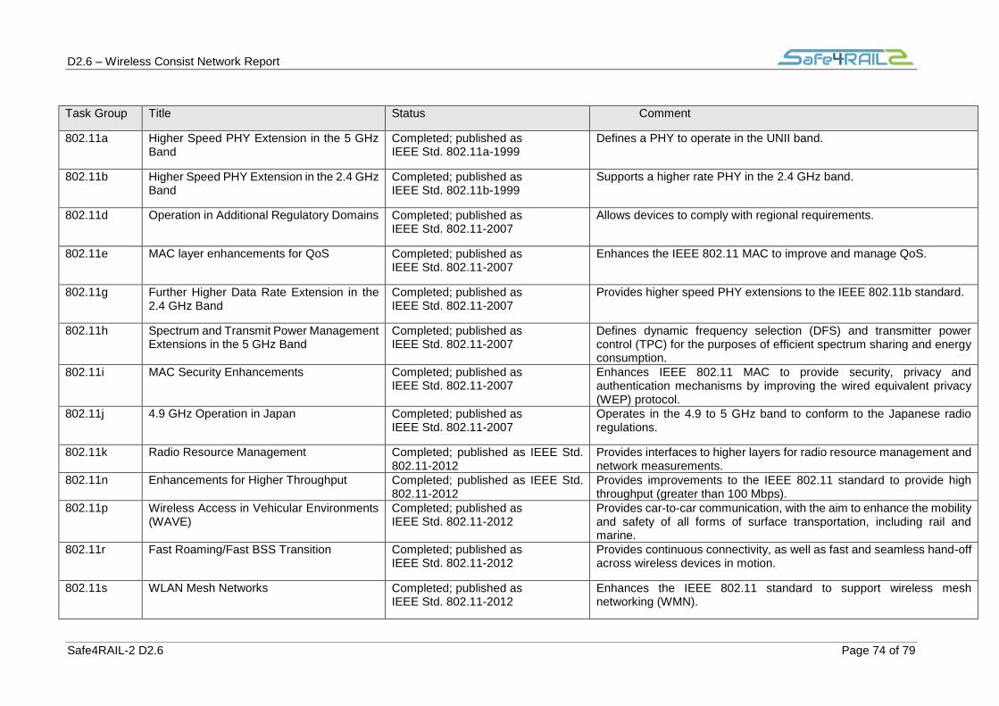
D2.6 – Wireless Consist Network Report
Safe4RAIL-2 D2.6 Page 74 of 79
Task Group Title Status Comment
802.11a Higher Speed PHY Extension in the 5 GHz Band
Completed; published as IEEE Std. 802.11a-1999
Defines a PHY to operate in the UNII band.
802.11b Higher Speed PHY Extension in the 2.4 GHz Band
Completed; published as IEEE Std. 802.11b-1999
Supports a higher rate PHY in the 2.4 GHz band.
802.11d Operation in Additional Regulatory Domains Completed; published as IEEE Std. 802.11-2007
Allows devices to comply with regional requirements.
802.11e MAC layer enhancements for QoS Completed; published as IEEE Std. 802.11-2007
Enhances the IEEE 802.11 MAC to improve and manage QoS.
802.11g Further Higher Data Rate Extension in the 2.4 GHz Band
Completed; published as IEEE Std. 802.11-2007
Provides higher speed PHY extensions to the IEEE 802.11b standard.
802.11h Spectrum and Transmit Power Management Extensions in the 5 GHz Band
Completed; published as IEEE Std. 802.11-2007
Defines dynamic frequency selection (DFS) and transmitter power control (TPC) for the purposes of efficient spectrum sharing and energy consumption.
802.11i MAC Security Enhancements Completed; published as IEEE Std. 802.11-2007
Enhances IEEE 802.11 MAC to provide security, privacy and authentication mechanisms by improving the wired equivalent privacy (WEP) protocol.
802.11j 4.9 GHz Operation in Japan Completed; published as IEEE Std. 802.11-2007
Operates in the 4.9 to 5 GHz band to conform to the Japanese radio regulations.
802.11k Radio Resource Management Completed; published as IEEE Std. 802.11-2012
Provides interfaces to higher layers for radio resource management and network measurements.
802.11n Enhancements for Higher Throughput Completed; published as IEEE Std. 802.11-2012
Provides improvements to the IEEE 802.11 standard to provide high throughput (greater than 100 Mbps).
802.11p Wireless Access in Vehicular Environments (WAVE)
Completed; published as IEEE Std. 802.11-2012
Provides car-to-car communication, with the aim to enhance the mobility and safety of all forms of surface transportation, including rail and marine.
802.11r Fast Roaming/Fast BSS Transition Completed; published as IEEE Std. 802.11-2012
Provides continuous connectivity, as well as fast and seamless hand-off across wireless devices in motion.
802.11s WLAN Mesh Networks Completed; published as IEEE Std. 802.11-2012
Enhances the IEEE 802.11 standard to support wireless mesh networking (WMN).

D2.6 – Wireless Consist Network Report
Safe4RAIL-2 D2.6 Page 75 of 79
Task Group Title Status Comment
802.11u Interworking with External Networks Completed; published as IEEE Std. 802.11-2012
Provides convergence to IEEE 802.11 and GSM by allowing multi-mode phones to join an IEEE 802.11 WLAN.
802.11v Wireless Network Management Completed; published as IEEE Std. 802.11-2012
Extends the IEEE 802.11 PHY and MAC layers to provide network management for STAs.
802.11w Protected Management Frames Completed; published as IEEE Std. 802.11-2012
Defines security mechanisms for management frames.
802.11y Contention-based Protocol Completed; published as IEEE Std 802.11y-2008
Provides contention-based protocols for operation in the 3.65 GHz band in the USA.
802.11z Extensions to Direct Link Setup Completed; published as IEEE Std 802.11z-2010
Provides an AP-independent direct link setup.
802.11aa Video Transport Stream Completed; published as IEEE Std 802.11z-2010
Defines various MAC enhancements for robust audio video streaming.
802.11ac Very High Throughput WLAN Completed; published as IEEE Std 802.11ac-2013
Provides high throughput (greater than 1 Gbps) operation in bands below 6 GHz.
802.11ad Very High Throughput WLAN operating in 60 GHz
Completed; published as IEEE Std 802.11ad-2012
Provides high throughput (greater than 1 Gbps) operation in 60 GHz
band.
802.11ae Prioritization of Management Frames Completed; published as IEEE Std 802.11ae-2012
Defines mechanisms for prioritizing IEEE 802.11 management frames using existing mechanisms for medium access.
802.11af Wireless LAN in the TV White Space Completed; published as IEEE Std 802.11af-2013
Defines legal requirements for channel access and coexistence in the TV white space.
802.11m IEEE 802.11 Standard Maintenance and
Revision
Active; published as IEEE Std 802.11-2012
Provides maintenance for the IEEE 802.11 standard by rolling published amendments into revisions of the IEEE 802.11 standard.
802.11ah Operation in Sub 1 GHz Frequencies Active Supports applications that benefit from range extension, such as smart meters.
802.11ai Fast Initial Link Set-up Active Reduces time for a WLAN client to securely setup an association in less than 100ms.
802.11aj Very High Throughput Active Operates in the millimetre-wave bands in China.

D2.6 – Wireless Consist Network Report
Safe4RAIL-2 D2.6 Page 76 of 79
Task Group Title Status Comment
802.11ak Enhancements for Transit Links Within
Bridged Networks
Approved Provides protocols and procedures to enhance the ability of IEEE 802.11 media through bridging by using IEEE 802.1 mechanisms across an IEEE 802.11 link.
802.11aq Pre-association Discovery (PAD) Approved Defines modifications to the IEEE 802.11 standard, including layers above the PHY layer, in order to enable delivery of pre-association service discovery information by IEEE 802.11 stations.
802.11ax High-efficiency Wireless LAN Approved Improving spectrum efficiency, area throughput and real-world performance in indoor and outdoor deployments.
Table 34 IEEE 802.11 task groups with completed specifications [68]

D2.6 – Wireless Consist Network Report
Safe4RAIL-2 D2.6 Page 77 of 79
Chapter 14 Annex ECHORING
ECHORING is a technology developed by R3 Communications. This is a MAC layer
communication protocol based on the token passing protocols.
Overview: a token passing method is a MAC (Medium Access Control) scheme which
has been used in several standards (e.g.: IEEE 802.4 or 802.5). The main principle of
a token ring topology relies on granting the access to the ring to all stations (see Figure
68). This “right” is forwarded among the stations by means of a token packet. Therefore,
every station has a successor and predecessor and can only access the token for a
limited period of time (namely, Token Holding Time (THT)).
Figure 68 Token ring topology
As this scheme allows obtaining bounded latencies, token ring protocols are a potential candidate for industrial trends. However, transmission errors (payload packet) or station failures (ring instabilities) are two of the biggest issues which must be addressed in token protocols. ECHORING introduces mechanisms to face these issues (see Section 2.6), such as: cooperative communication, evolved failure tolerance mechanisms, and adaptation of error handling strategy.
ECHORING is developed over chipsets from TI (Texas Instruments). It runs on the WiLink 8 modules.
Figure 69. ECHORING evaluation kit.

D2.6 – Wireless Consist Network Report
Safe4RAIL-2 D2.6 Page 78 of 79
Chapter 15 Annex WISA
Protocol Stack: WISA is based on Based on IEEE 802.15.1 (Bluetooth). The medium
access technique is TDMA (Time division multiple access) with FDD (Frequency
Division Duplex). The use of FDD implies that the communication from base station to
sensor (Downlink) and from sensors to base station (Uplink) occurs at different
frequencies:
- Downlink (i.e. from base station to sensors) is always active in order to establish frame and slot synchronization, enabling the device to quickly find its own timeslot and manage the TDMA scheme [33].
- Uplink is composed of 4 channels/frequencies which are only active when data is available. Data is transmitted in parallel for each channel, as depicted in Figure 70. Because of that, the base station is equipped with a transceiver able to receive up to four channels at the same time (Figure 71). These channels are divided into superframes of 2048 µs composed of 30 timeslots, able to support packets up to 64 bits. Furthermore, in order to avoid interference and enhance reliability, Frequency Hopping (FH) is additionally applied after each superframe with a carrier spacing of 1 MHz [69].
Figure 70 WISA frame structure [69]
Figure 71 WISA frame definition [70]

D2.6 – Wireless Consist Network Report
Safe4RAIL-2 D2.6 Page 79 of 79
Device Types [33]: a WISA network supports the following devices (see Figure 72):
- WSIX (Wireless Sensor Interface for proximity services). This is a sensor which
uses WISA technology and is connected to a WSP (Wireless Sensor Pad)
- A WSP is a WISA communication module which allows the connection of
several WSIX.
- The WIOP is a sensor distribution box which enables the connection between
WISA sensors (WSIX) and sensors from other technologies.
- The WDIO (Wireless Devices I/O module) has the role of connecting WISA
signals to a field bus.
Figure 72 WISA devices [33]
Regarding network topologies, WISA uses a star topology (see Figure 73); therefore,
there is a one-to-one connection between a wireless device and a base station. The
base stations are connected to the control network via a wired field bus.
Figure 73 WISA topology [69]