d2.6 final system test cases report
TRANSCRIPT

11/11/2014
Information and Communications Technologies Policy Support Programme (the “ICT PSP”) Information Society and Media Directorate-General Grant agreement no.: 325075 Pilot type A
D2.6 Final System Test Cases Report
Version number: Version 1.0 Main author: Frank Brennecke Dissemination level: PU Lead contractor: ERTICO – ITS Europe Due date: Delivery date: 11.11.2014 Delivery date updated document

D2.6 Final System Test Cases Report
22/10/2014 2 Version 1.0
Control sheet
Version history
Version Date Main author Summary of changes
0.1 04.02.2014 Frank Brennecke Template
0.2 11.11.2014 Frank Brennecke Input from MS
0.9 19.11.2014 Andy Rooke Review
1.0 19.11.2014 Frank Brennecke Added Ch 4.
Name Date
Prepared Frank Brennecke 22.10.2014
Reviewed Andy Rooke 03.12.2014
Authorized Andy Rooke 03.12.2014
Circulation
Recipient Date of submission
Project partners 03.12.2014
European Commission 03.12.2014

D2.6 Final System Test Cases Report
22/10/2014 3 Version 1.0
TABLE OF CONTENTS
1 TERMS AND ABBREVIATIONS ................................................................................................................... 6
1.1 TERMS ..................................................................................................................................................... 6
1.2 ABBREVIATIONS ...................................................................................................................................... 8
2 INTRODUCTION ..................................................................................................................................... 11
2.1 PURPOSE OF THIS DOCUMENT ............................................................................................................. 11
2.2 STRUCTURE OF DOCUMENT .................................................................................................................. 11
2.3 HEERO CONTRACTUAL REFERENCES ..................................................................................................... 11
3 IMPLEMENTATION OVERVIEW ............................................................................................................... 13
3.1 BELGIUM ............................................................................................................................................... 13
3.1.1 ECALL FLAG IN MOBILE NETWORK ................................................................................................ 13
3.1.2 FILTERING INSTANCE ..................................................................................................................... 13
3.1.3 PSAP IMPLEMENTATION ............................................................................................................... 13
3.2 BULGARIA .............................................................................................................................................. 14
3.2.1 ESTABLISHING ECALL ENVIRONMENT ........................................................................................... 14
3.2.2 ECALL TEST SERVICE IMPLEMENTATION ....................................................................................... 15
3.2.3 ADAPTATION OF THE EXISTING PSAP ............................................................................................ 15
3.3 DENMARK .............................................................................................................................................. 16
3.3.1 GENERAL OVERVIEW OF THE TECHNICAL SOLUTION .................................................................... 16
3.3.2 TEST SYSTEMS ............................................................................................................................... 17
3.3.3 IMPLEMENTATION ACTIVITIES PSAP ............................................................................................. 18
3.3.4 IMPLEMENTATION ACTIVITIES MNO ............................................................................................. 19
3.3.5 IMPLEMENTATION ACTIVITIES IVS ................................................................................................ 19
3.4 LUXEMBOURG ....................................................................................................................................... 20
3.4.1 THE CORE FUNCTIONALITY ............................................................................................................ 20
3.4.2 HARDWARE AND SOFTWARE REQUIRED ...................................................................................... 21
3.5 SPAIN ..................................................................................................................................................... 22
3.5.1 PUBLIC SAFETY ANSWERING POINT (PSAP) ................................................................................... 22
3.5.2 MOBILE NETWORK OPERATOR (MNO) .......................................................................................... 25
3.5.3 IN-VEHICLE SYSTEMS (IVS) ............................................................................................................. 26
3.5.4 P2W ............................................................................................................................................... 27
3.6 TURKEY .................................................................................................................................................. 33
3.6.1 MOBILE NETWORK ........................................................................................................................ 33
3.6.2 IVS.................................................................................................................................................. 33

D2.6 Final System Test Cases Report
22/10/2014 4 Version 1.0
3.6.3 PSAP .............................................................................................................................................. 33
3.6.4 FIXED NETWORK OPERATOR ......................................................................................................... 34
4 IMPLEMENTATION RESULTS .................................................................................................................. 35
4.1 IVS IMPLEMENTATION .......................................................................................................................... 35
4.2 PSAP IMPLEMENTATION ....................................................................................................................... 35
4.3 MNO IMPLEMENTATION ....................................................................................................................... 36

D2.6 Final System Test Cases Report
22/10/2014 5 Version 1.0
Figures
FIGURE 1: PSAP IMPLEMENTATION 14
FIGURE 2: SYSTEM OVERVIEW 17
FIGURE 3: SYSTEM UNDER TEST 18
FIGURE 4: LUXEMBOURG ECALL PSAP ARCHITECTURE 21
FIGURE 5: COORDCOM OPERATOR POSITION 23
FIGURE 6: PSAP DISPATCHING PROCESS 24
FIGURE 7: PROTOCOLS INVOLVED IN EMERGENCY MANAGEMENT 25
FIGURE 8: CTAG PILOT VEHICLES AND HMI INTEGRATION EXAMPLES. 26
FIGURE 9: CTAG TRACKING TOOL AND AUTOMATIC ECALL REMOTE TRIGGERING. CTAG DATA LOGGER. 26
FIGURE 10: P2W ECALL SYSTEM 28
FIGURE 11: MOTORBIKE FOR INCIDENT DETECTION 29
FIGURE 12: DAMAGED HELMET 31
FIGURE 13: P2W TEST ARCHITECTURE 32
FIGURE 14: P2W WITH IVS INSTALLED 32
Tables
TABLE 1 CTAG INTEROPERABILITY RESULTS IN ECALL#2 TESTFEST – ESSEN 2013 SUMMARY RESULTS .............. 27
TABLE 2 ECALL P2W HELMET USAGE .................................................................................................................... 30
TABLE 3 USAGE AND INCIDENTS LOGGED ............................................................................................................ 30
TABLE 4 ECALL P2W TEST RESULTS ....................................................................................................................... 33

D2.6 Final System Test Cases Report
22/10/2014 6 Version 1.0
1 Terms and abbreviations
1.1 Terms
TERM DESCRIPTION
112 single European emergency call number supporting
Teleservice 12 (ETSI TS 122 003)
Call Termination termination of call and freeing up of line (usually achieved by
hanging up the receiver or pressing ‘end call’ or similar on
screen)
Mobile network
Mobile radio network based on 3GPP standards for circuit
switched telephony, also known as GSM (2G) or UMTS (3G)
E112 emergency communications service using the single European
emergency call number, 112, which is enhanced with location
information of the calling user TS12
eCall emergency call generated either automatically via activation of
in-vehicle sensors or manually by the vehicle occupants; when
activated it provides notification and relevant location
information to the most appropriate Public Safety Answering
Point, by means of a mobile network, carries a defined
standardized minimum set of data (MSD) notifying that there
has been an incident that requires response from the
emergency services, and establishes an audio channel
between the occupants of the vehicle and the most appropriate
Public Safety Answering Point
eCall discriminator
one of two flags included in the emergency call set-up
message within the Service Category IE, that may be used by
the mobile network to filter and route automatically and
manually initiated eCalls to a designated PSAP term “identifier”
not used
eCall In-band Modem (eIM) Modem pair (consisting of transmitters and receivers at IVS
and PSAP) that operates full-duplex and allows reliable
transmission of eCall Minimum Set of Data from IVS to PSAP
via the voice channel of the emergency voice call through
cellular and PSTN networks.
eCall service
end-to-end emergency service to connect occupants of an
affected vehicle to the most appropriate PSAP via an audio link
across a PLMN together with the transfer of a minimum set of
data to the PSAP
eCall transaction
establishment of a mobile wireless communications session
across a public wireless communications network and the
transmission of a minimum set of data from a vehicle to a
D2.6 Final System Test Cases Report
22/10/2014 7 Version 1.0
public safety answering point and the establishment of an
audio channel between the vehicle and the PSAP
in-vehicle equipment
equipment within the vehicle that provides or has access to in-
vehicle data required for the minimum set of data and any
other data that is to be sent as part of or complementary to the
minimum set of data to effect the eCall transaction via a mobile
network providing a link between the vehicle and a means of
enacting the eCall service via a mobile network
in-vehicle system (IVS) in-vehicle equipment together with the means to trigger,
manage and effect the eCall transaction
Minimum Set of Data (MSD)
standardized data concept comprising data elements of
relevant vehicle generated data essential for the performance
of the eCall service
[EN 15722:2011]
most appropriate PSAP PSAP defined beforehand by responsible authorities to cover
emergency calls from a certain area or for emergency calls of a
certain type
network access device (NAD) device providing communications to a mobile wireless
communications network with homogeneous handover
between network access points
public safety answering point
(PSAP)
physical location working on behalf of the national authorities
where emergency calls are first received under the
responsibility of a public authority or a private organisation
recognised by the national government
D2.6 Final System Test Cases Report
22/10/2014 8 Version 1.0
1.2 Abbreviations
TERM DEFINITION
2G Second generation mobile network, based on 3GPP standards, also
called GSM
3G Third generation mobile network, based on 3GPP standards, also called
UMTS
3GPP Third generation partnership Project
ACK Acknowledgement
AIeC Automatic Initiated eCall
API application programming interface
AREU Azienda Regionale Emergenza Urgenza
AT Attention (part of modem instruction, e.g. to dial as specified in ETSI TS
127 007)
AVL Automatic Vehicle Location
BSC Base Station Controller
CAN Controller Area Network
CITA road traffic management centre (Luxembourg)
CRC Cyclic Redundancy Check
CLI Caller Location Information
CTI Computer Telephony Integration
DGT Traffic General Directorate (Spain)
DL Data Logger
ETSI European Telecommunications Standards Institute
ECC Emergency Control Centre
EPT Entreprise des Postes et Télécommunications (Luxembourg)
ESA European Space Agency
EUCARIS EUropean CAR and driving license Information System
GIS Geographic Information System
GMV Grupo Mecánica del Vuelo Sistemas, S.A.U.
GNSS Global Navigation Satellite System
GSM Global System for Mobile communications, also called 2G
HGV Heavy Goods Vehicle
HLAP High Level Application Requirements

D2.6 Final System Test Cases Report
22/10/2014 9 Version 1.0
HLR Home Location Registry
HMI Human Machine Interface
HPLMN Home Public Land Mobile Network
HW Hardware
ICT Information and Communications Technology
IMEI International Mobile Equipment Identity
IMSI International Mobile Subscriber Identity
ITS Intelligent Transportation System
IVR Interactive voice response
IVS In-Vehicle System
KPI Key performance indicator
LCV Light commercial vehicle
MIeC Manually Initiated eCall
MNO Mobile Network Operator
MSISDN Mobile Subscriber ISDN (integrated services digital network)
MSC Mobile Switching Centre
MSD Minimum Set of Data (EN 15722)
NAD Network Access Device (e.g. a GSM or UMTS module)
NRN Network Routing Number
OBD On-Board Diagnostics
OBU on-board-unit
OEM original equipment manufacturer
P2W Powered-two-wheel vehicles
PABX private automatic branch exchange
PER packed encoding rules (ASN.1)
PLMN Public Land Mobile Network
PSAP Public Safety Answering Point
PSTN public switched telephone network
SIM Subscriber Identity Module (GSM/3GPP)
SUT System Under Test
SW Software
TPS Third Party Service
TPSP third Party Service Provider

D2.6 Final System Test Cases Report
22/10/2014 10 Version 1.0
TS12 Teleservice 12 ETSI TS 122 003, see also 112
UMTS Universal Mobile Telecommunication System, also called 3G
USIM User Service Identity Module
VIN Vehicle Identification Number
VLR Visited Location Register

D2.6 Final System Test Cases Report
22/10/2014 11 Version 1.0
2 Introduction
2.1 Purpose of this Document
This deliverable document describes the Final System Test Cases Report and will report the
final implementation results also related to technical and operational upgrades. It will also
give an overview about the implementation of eCall in the different Member States. A full
description of the implementation is already available in the document D2.3 Hardware and
Software implementation
2.2 Structure of Document
This document describes the implementation results separately for each member state pilot
site. There is also a common chapter comparing the results.
2.3 HeERO Contractual References
HeERO is a Pilot type A of the ICT Policy Support Programme (ICT PSP), Competitiveness
and Innovation Framework Programme (CIP). It stands for Harmonised eCall European Pilot.
The Grant Agreement number is 325075 and project duration is 24 months, effective from 01
January 2013 until 31 December 2014. It is a contract with the European Commission, DG
CONNECT.
The principal EC Project Officer is:
Aude Zimmermann EUROPEAN COMMISSION DG CONNECT Office: BU 31 – 6/35 B - 1049 Brussels Tel: +32 296 2188 E-mail: [email protected]
One other Project Officer will follow the HeERO project:
Dimitrios AXIOTIS
Address to which all deliverables and reports have to be sent:
Aude Zimmermann EUROPEAN COMMISSION

D2.6 Final System Test Cases Report
22/10/2014 12 Version 1.0
DG CONNECT BU 31 – 6/35 B - 1049 Brussels Tel: +32 296 2188
By mail: [email protected]
Any communication or request concerning the grant agreement shall identify the grant
agreement number, the nature and details of the request or communication and be submitted
to the following addresses:
European Commission Communications Networks, Content and Technology B-1049 Brussels Belgium
By electronic mail: [email protected]
D2.6 Final System Test Cases Report
22/10/2014 13 Version 1.0
3 Implementation Overview
The paragraphs below describe the implementation for IVS, PSAP and Mobile Network
Providers - if applicable - on each pilot site.
3.1 Belgium
3.1.1 eCall flag in Mobile network
eCall flag implementation requirements 3.1.1.1
For the purpose of the HeERO pilot project in Belgium, the Mobistar mobile network was
used to verify the functioning of the public eCall implementation. For this purpose, the mobile
network was adapted to detect the eCall flag as part of the TS12 emergency call.
eCall pilot implementation plan 3.1.1.2
Prior to the real HeERO pilot, an internal Mobistar validation of the eCall function was
conducted in the Mobistar Lab environment. This was performed after the software upgrade
of the Mobistar MSC test platform had been carried out.
Once validated, the rollout of the software upgrade was performed and the eCall function
was activated in one operative MSC (covering the HeERO pilot site), for a limited amount of
time (during HeERO pilot).
3.1.2 Filtering instance
Belgium decided to have a special way of implementation of eCall a filtering instance was
created this route of implementation was selected owing to concerns over high volumes of
false or inappropriate calls flooding the PSAP. This filtering instance was implemented at
Touring on a dedicated server using the “eCall Router” software of OECON Product &
Services GmbH. According to the specifications Touring provided material in order to perform
the installation.
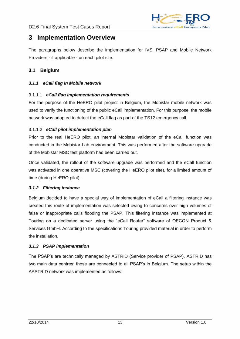
3.1.3 PSAP implementation
The PSAP’s are technically managed by ASTRID (Service provider of PSAP). ASTRID has
two main data centres; those are connected to all PSAP’s in Belgium. The setup within the
AASTRID network was implemented as follows:

D2.6 Final System Test Cases Report
22/10/2014 14 Version 1.0
Figure 1: PSAP implementation
The gateway software was created as a custom development for Belgium. This software
allows a redundant setup, which can connect to the filtering instance. Since the EN16102
protocol (TPSP protocol) was chosen for the connection to the filtering instance, this also
allows connections to private eCall providers.
3.2 Bulgaria
3.2.1 Establishing eCall environment
IVS development 3.2.1.1
ICOM
A prototype of eCall IVS by ICOM was based on common fleet management equipment,
manufactured by ICOM, where some extra features for eCall like in-band modem were
added. 10 vehicles have been equipped.
TUS
One prototype and one working module have been built by TUS. External hardware for the
IVS include: 12V power supply; GPS/GSM antennas; audio I/O connection; airbag
deployment indication connection.
eCall flag implementation 3.2.1.2
MNO provided a temporary workaround for "eCall flag" simulation – mainly a re-mapping of
the test number as call-routing in the mobile switching centre(s) to call PSAP/112 via a
dedicated number until real eCall flag implementation.
Astrid Backbone
3rd partyExtranet
CIC LAN
FW
Datacenter LAN
FW
DMZ
FW
FW
WEB+
DB
XMLGW
WKS
Datacenter LAN
FW
DMZ
FW
FW
WEB+
DB
XMLGW
EN-16102 (XML)
DB Update
Web/XML
Datacenter 1 Datacenter 2
D2.6 Final System Test Cases Report
22/10/2014 15 Version 1.0
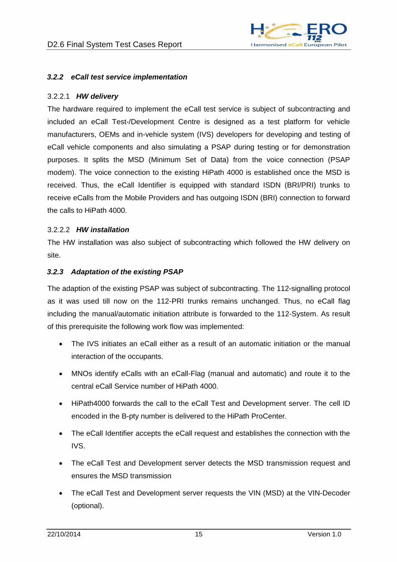
3.2.2 eCall test service implementation
HW delivery 3.2.2.1
The hardware required to implement the eCall test service is subject of subcontracting and
included an eCall Test-/Development Centre is designed as a test platform for vehicle
manufacturers, OEMs and in-vehicle system (IVS) developers for developing and testing of
eCall vehicle components and also simulating a PSAP during testing or for demonstration
purposes. It splits the MSD (Minimum Set of Data) from the voice connection (PSAP
modem). The voice connection to the existing HiPath 4000 is established once the MSD is
received. Thus, the eCall Identifier is equipped with standard ISDN (BRI/PRI) trunks to
receive eCalls from the Mobile Providers and has outgoing ISDN (BRI) connection to forward
the calls to HiPath 4000.
HW installation 3.2.2.2
The HW installation was also subject of subcontracting which followed the HW delivery on
site.
3.2.3 Adaptation of the existing PSAP
The adaption of the existing PSAP was subject of subcontracting. The 112-signalling protocol
as it was used till now on the 112-PRI trunks remains unchanged. Thus, no eCall flag
including the manual/automatic initiation attribute is forwarded to the 112-System. As result
of this prerequisite the following work flow was implemented:
The IVS initiates an eCall either as a result of an automatic initiation or the manual
interaction of the occupants.
MNOs identify eCalls with an eCall-Flag (manual and automatic) and route it to the
central eCall Service number of HiPath 4000.
HiPath4000 forwards the call to the eCall Test and Development server. The cell ID
encoded in the B-pty number is delivered to the HiPath ProCenter.
The eCall Identifier accepts the eCall request and establishes the connection with the
IVS.
The eCall Test and Development server detects the MSD transmission request and
ensures the MSD transmission
The eCall Test and Development server requests the VIN (MSD) at the VIN-Decoder
(optional).

D2.6 Final System Test Cases Report
22/10/2014 16 Version 1.0
Once the MSD + VIN data are received, the eCall Test and Development server
initiates a second voice call via its outbound trunks back to HiPath 4000 to a specific
service number.
Once the call taker accepts the call, the eCall Test and Development server connects
both calls and establishes an end-to-end voice connection between IVS and the call
taker. Instantly the call taker sees the covered area of the mobile antenna.
If necessary the call taker may trigger resend and call back functionalities of the eCall
Test and Development server by utilizing special buttons in the user interface.
3.3 Denmark
3.3.1 General overview of the technical solution
The routing of 112-calls is based on geographical dependencies by the four PLMNs in
Denmark. A 112-call will always be routed to the nearest PSAP.
The three PSAPs in Denmark are operated by the National Police (2 PSAPs) and the
Copenhagen Fire Brigade (1 PSAP).
The Copenhagen Fire Brigade (CFB) and the National Police make use of the same PBX
and Call Centre vendor, but the PBX-models are not the same, and each instance is
programmed very differently, as they have different needs.
Also the PSAP applications used by the two PSAP-operators are different proprietary legacy
solutions developed by their own group IT or by third party vendors according to
specifications.
The eCall service in Denmark will use the existing LIF-server infrastructure in the PSAP
network for mobile phones, and the recently launched 112-App.
As 112-calls are routed by the PLMNs to the nearest PSAP, all three PSAPs will be equipped
with an in-band modem solution making them able to extract the MSD-information and
placing it on the LIF-server. By end 2014 the implementation at National Police is not finished
due to a need for a total upgrade of the PBX-solution, therefore only the PSAP at the
Copenhagen Fire Brigade is ready to receive eCall following the decided national solution.

D2.6 Final System Test Cases Report
22/10/2014 17 Version 1.0
Figure 2: System overview
3.3.2 Test systems
PSAP-SUT 3.3.2.1
In order to test the eCall functionality without disrupting the running 112-service in Denmark
a test PSAP environment (PSAP-SUT) was established at the Copenhagen Fire Brigade.

D2.6 Final System Test Cases Report
22/10/2014 18 Version 1.0
Figure 3: System under test
The PSAP-SUT uses the same components as the final system in order to create an
environment as close to the real system as possible. The PSAP-SUT uses an ISDN PRI and
an in-band modem in conjunction with a modem server.
The ISDN PRI is a separate ISDN with its own pre designated number for test purposes only,
to avoid interfering with the ordinary 112-calls.
In order to keep trace of errors and to measure KPIs within the defined performance
framework a logging of relevant data was performed at the PSAP-SUT and at the Test IVS.
Test IVS 3.3.2.2
Three different IVS-vendors were selected for the Danish eCall pilot project, but only two
managed to deliver Dormant SIM (eCall-only) capable IVS-units. A test fleet of 10 vehicles
was equipped with IVS-systems from both vendors.
3.3.3 Implementation activities PSAP
Copenhagen Fire Brigade 3.3.3.1
In order to establish the testing facilities a number of prerequisites have been carried out.

D2.6 Final System Test Cases Report
22/10/2014 19 Version 1.0
Establishment of an ISDN PRI Flex with 8 channels, acquired through the
governmental framework agreement. The acquisition was made by the group IT at
CFB.
In order for the ISDN PRI to function an ISDN PRI card was inserted and configured
in the PBX located at the CFBs headquarters.
After configuring the ISDN PRI and testing that calls actually are received by the
PBX, IVR-functions for the eCall testing have been programmed in CFB’s call centre
solution Solidus eCare.
Finally the eCall PSAP modem was installed and configured.
The above tasks were carried out by CFBs service provider.
Parallel to the testing of the eCall functionality in the test environment the necessary changes
in the Copenhagen Fire Brigades PSAP application were carried out in order to support the
eCall service.
The necessary modifications in the PSAP application and subsequent testing were carried
out by group IT at CFB. The modification involves among other:
GIS-display
Enriched MSD-display
National Police 3.3.3.2
The test, and later on production environment will use a dedicated eCall LIF-server hosted by
the Danish National Police.
All three PSAPs will establish a connection to this server in order to set and retrieve MSD-
information.
This was the agreed plan however the National Police took the decision to leave the
consortium owing to technical difficulties. However once the difficulties are resolved the
identified plan will be resumed, but outside of the lifetime of this project (Q1 2015)
3.3.4 Implementation activities MNO
In order to pass the eCall flag, the Danish PLMNs will patch their AXEs. Each PLMNs
infrastructure is in the process of being upgraded, with verifications tests expected to be
carried out H1 2015.
3.3.5 Implementation activities IVS
The IVS-vendors selected for the Danish eCall pilot are Fujitsu-Ten and GMV.

D2.6 Final System Test Cases Report
22/10/2014 20 Version 1.0
The pilot has used refitted IVS-equipment in 10 vehicles from the Danish Ministry of
Transportation (Trafikstyrelsen) representing both vendors. SIM cards used were:
Normal domestic SIM Card connecting to one of the four PLMNs
Simulated Dormant SIM Card connecting to two of the other three PLMNs
Normal roaming SIM Card, actual PLMNs used are not known
3.4 Luxembourg
3.4.1 The core functionality
In Phase 1 the Luxembourg partners installed IVS units into a fleet of six test vehicles. These
triggered test eCalls both manually and automatically. The IVS units used were provided by
FICOSA, NXP and Fujitsu TEN. They comply with the CEN and ETSI standards. Special IVS
systems from FICOSA have been used in transporters to send the MSD with the extended
data set as defined in the CEN document on HGV eCall.
The eCalls were sent via the Luxembourg MNO partner in the project, POST Luxembourg.
POST Luxembourg implemented the eCall flag in the middle of 2014.
NB: It is important to note that POST Luxembourg discovered an important potential routing
problem after implementing the eCall flag in their switches (Ericsson). MNOs should
therefore verify that the specified eCall routing, through Bits 6 and 7, can be handled by their
switches. As Luxembourg only has ever had one PSAP there has never been a need to
implement a specific routing for 112 calls other than directly to this number. As the eCall
server solution in Luxembourg uses a long number interface calls could not be routed to this
number even though the eCall Flag was activated, because the Bit routing could not be
followed. A new version of the MSC software will be delivered in Q2 2015 that will correct
this problem.
The MNO will eventually deliver eCall messages to the designated entry points in the POST
Luxembourg network. The PSAP is connected via ISDN to the network.
At the PSAP entry point manual and automated eCalls are handled according to the
functional design. This does not yet include the connection with EUCARIS due to ongoing
discussions occasioned by Luxembourg’s strict privacy laws.
ECalls concerning HGV and transports of dangerous goods was also examined in
Luxembourg. Parallel ESA project dangerous goods tracking service is in the process of

D2.6 Final System Test Cases Report
22/10/2014 21 Version 1.0
being implemented as a prototype (DG-Trac service). The goal is to provide specific
information about potentially dangerous goods loaded in a vehicle to the operator in addition
to the MSD information. So far only recommendations have been made as to possible
specifications and standards.
3.4.2 Hardware and software required
PSAP (112) 3.4.2.1
In order not to disturb the operational processes in the Luxembourg PSAP, the pilot was
performed on separate systems which were however installed at the PSAP. ECall router and
server software were installed as a virtual machine on the standard PSAP server. An
ISDN/IP gateway was connected to the server via IP-based Ethernet and to 4 S0 interfaces
coming from the PSAP PBX.
The eCall infrastructure will be implemented into the Luxembourg PSAP as shown in the
following figure.
Figure 4: Luxembourg eCall PSAP architecture
For the operator a new separate PC will be installed on a separate desk in the PSAP. During
manual tests trained PSAP operators have operated this PC.

D2.6 Final System Test Cases Report
22/10/2014 22 Version 1.0
3.5 Spain
3.5.1 Public Safety Answering Point (PSAP)
Intermediate PSAP in DGT 3.5.1.1
The architecture chosen in Spanish eCall pilot is based on an intermediate PSAP, hosted by
the Traffic General Directorate (DGT). Mainly, this intermediate PSAP will have a filtering
function for every manual or automatic eCall before transferring it to the appropriate Regional
112 or discarding it. This pilot architecture might be different in some aspects from the one
which has been tested in the pilot, anyhow, and it is under discussion at present.
For this Spanish eCall pilot, two different HW and SW platforms were supplied for eCall
reception and handling: CoordCom (Ericsson) and SENECA (Telefónica). Some different
DGT information systems were integrated with both platforms, mainly DGT ATEX (Telematic
Access for External Organizations) and LINCE (DGT’s alert system)
3.5.1.1.1 Telefónica PSAP
PSAP is based on Telefónica emergency platform Séneca. This platform includes integration
bus based on OASIS EENA standards which allows an easy integration and interaction with
112 PSAPs, GIS system to improve eCall location, and Computer Telephony Integration
(CTI) through CISCO JTAPI with DGT corporate telephony.
Software adaptations for eCall and integrations with DGT systems were developed on the
platform in the pilot scope.
Hardware support for platform is based on VMWare virtual machines. Voice integration with
DGT Cisco CallManager PBX is obtained through trunk SIP linking Séneca MSD decoder.
Intermediate PSAP has available two agent workstations with Séneca software ready to use
for Spanish pilot activities.
3.5.1.1.2 Ericsson PSAP
The chosen system implementation for the Spanish eCall pilot was based on the following
HW Platform:
1 combined database/application/communication server, for intermediate DGT PSAP
system, comprising:
o 1 high availability HP Proliant DL 380p G8 server with redundancy in hard
disks, network interface cards, power supply and fans.

D2.6 Final System Test Cases Report
22/10/2014 23 Version 1.0
o 1 ISDN communication media board from Dialogic Corporation to handle
telephony and VoIP communication and thus, receive the eCall in the system
1 Client workstation, for intermediate PSAP Operator, based on HP Compaq 8200,
supplied with 3 monitors
Figure 5: CoordCom Operator position
The chosen SW platform was based on CoordCom 5.4 release. The eCall functionality was
introduced in CoordCom products starting from CoordCom 5.2 and it has been used in
HeERO1 Swedish and Croatian pilots. The platform includes a GIS module: ResQMap 3.2;
and the ISDN communication module where MSD is received and decoded without needing
additional HW. It communicates with external In-Vehicle Systems (IVS) according to the
eCall standard.
Regional 112 Pass 3.5.1.2
The integration between intermediate PSAP and regional 112 PSAP has been implemented
in order to allow real emergency eCalls to be transferred from intermediate PSAP to the right
geographical 112 PSAP.
Each Spanish region has its own 112 service, with its particular protocols, procedures and
systems to solve an incident. In the Spanish eCall pilot, a single interface has been defined
in order to make sure the intermediate PSAP in DGT always sends the same information, no
matter which geographical 112 PSAP is the recipient of the information.
The following figure illustrates the process involving the incident management made in the
112 PSAPs.

D2.6 Final System Test Cases Report
22/10/2014 24 Version 1.0
Figure 6: PSAP dispatching process
3.5.1.2.1 Regional 112 PSAP implementation strategy
From a technical point of view, the integration solution has been achieved using an
interoperability bus that coordinates and integrates the communications between the
intermediate PSAP and the regional 112 PSAP.
This interoperability bus uses models made with OASIS emergencies protocols based on
EDXL. The concrete protocol will be a Telefónica protocol ESAP for communication between
regional or national PSAPs. This protocol will provide:
Connectivity
Intelligent routing
Synchronous and asynchronous messaging
Transaction management
Information transformation
Safe communications
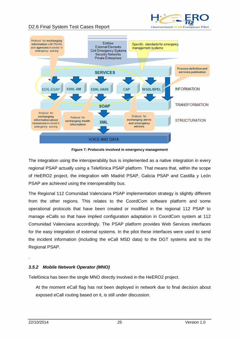
The following figure illustrates the different protocols and possible interactions within the
management of emergencies.
D2.6 Final System Test Cases Report
22/10/2014 25 Version 1.0
Figure 7: Protocols involved in emergency management
The integration using the interoperability bus is implemented as a native integration in every
regional PSAP actually using a Telefónica PSAP platform. That means that, within the scope
of HeERO2 project, the integration with Madrid PSAP, Galicia PSAP and Castilla y León
PSAP are achieved using the interoperability bus.
The Regional 112 Comunidad Valenciana PSAP implementation strategy is slightly different
from the other regions. This relates to the CoordCom software platform and some
operational protocols that have been created or modified in the regional 112 PSAP to
manage eCalls so that have implied configuration adaptation in CoordCom system at 112
Comunidad Valenciana accordingly. The PSAP platform provides Web Services interfaces
for the easy integration of external systems. In the pilot these interfaces were used to send
the incident information (including the eCall MSD data) to the DGT systems and to the
Regional PSAP.
.
3.5.2 Mobile Network Operator (MNO)
Telefónica has been the single MNO directly involved in the HeERO2 project.
At the moment eCall flag has not been deployed in network due to final decision about
exposed eCall routing based on it, is still under discussion.

D2.6 Final System Test Cases Report
22/10/2014 26 Version 1.0
3.5.3 In-Vehicle Systems (IVS)
CTAG IVS 3.5.3.1
CTAG has equipped 4 vehicles with CTAG IVS. The HMI has been integrated in the
instrument board of each vehicle.
Figure 8: CTAG Pilot Vehicles and HMI integration examples.
In addition, CTAG has developed a tool within the eCall tracking centre which allows
monitoring the tests remotely and generating events in real time during the operation phase
such as automatic eCall triggering through CTAG data logger, also installed within each
vehicle.
Figure 9: CTAG Tracking tool and automatic eCall remote triggering. CTAG data logger.

D2.6 Final System Test Cases Report
22/10/2014 27 Version 1.0
In order to ensure interoperability of CTAG IVS, the equipment was tested together with 22
IVS providers against 11 PSAP’s across Europe in the interoperability event eCall#2
Testfest – Essen 2013, obtaining excellent results.
Table 1 CTAG Interoperability results in eCall#2 Testfest – Essen 2013 summary results
FICOSA IVS 3.5.3.2
The FICOSA IVS implementation will consist of two major items:
IVS unit including HW and SW implementation
HMI unit including HW implementation
The strategy considered will be focused on autonomous installation, so there has not been a
vehicle integration (in terms of CAN connection and vehicle wiring harness); the installation
was detachable from vehicle and then able to be added potentially to a new different vehicle
if requested or for testing purposes is needed.
U-10A (GMV’s IVS) 3.5.3.3
GMV’s IVS is based on the on-board unit model U10, which was modified to comply with the
specifications and standards of pan-European eCall. Some Hardware modifications were
made in order to incorporate audio functionalities to GMV’s IVS. In particular, microphone
and speaker features have been added. Moreover, a new amplification stage has been
integrated before audio signals reach microphone and speaker elements. Also some
Software modifications included in the framework of HeERO2 project were devoted to the
implementation of a functional eCall application running on GMV’s IVS.
In order to ensure interoperability of GMV’s IVS, the equipment was tested against different
PSAPs across Europe in the interoperability event eCall#2 Testfest – Essen 2013 and
eCall#3 Testfest – Vigo 2014, obtaining excellent results.
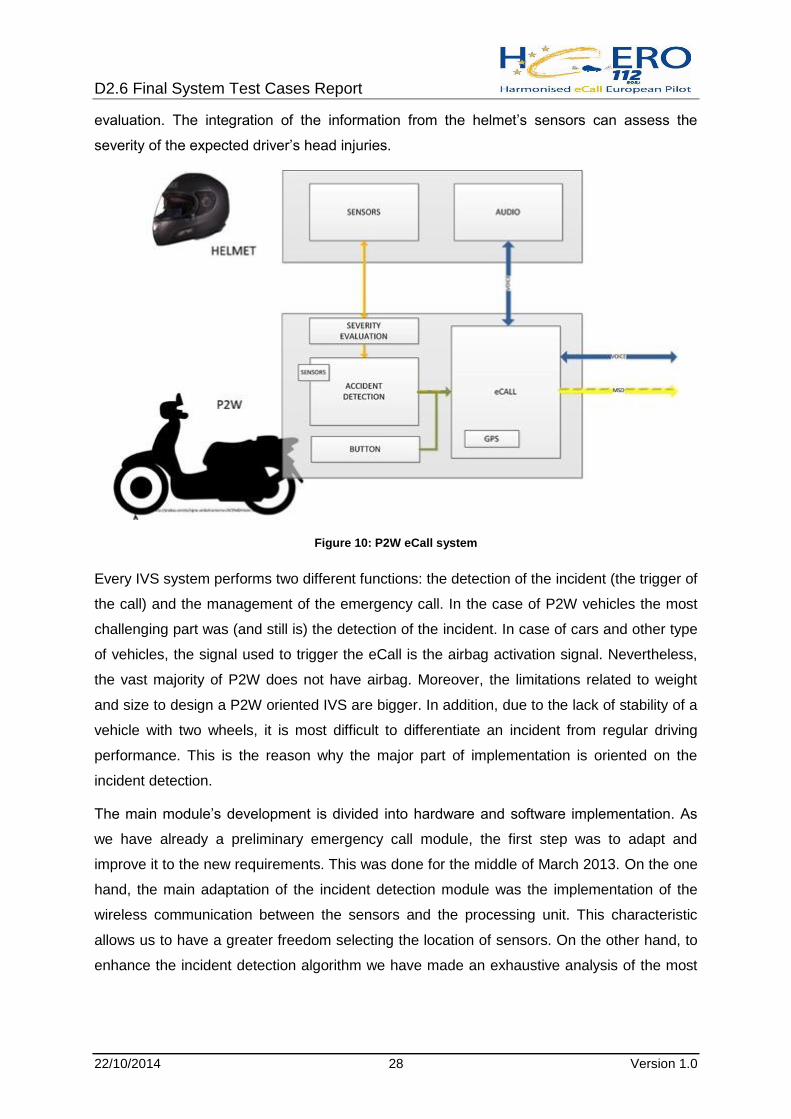
3.5.4 P2W
The implementation of the P2W eCall system is made up of two independent modules: the
on board module and the helmet’s module. The main module detects the incident and
manages the emergency call. The module in the helmet allows a more complete incident
Group OK NO OK NO
Mandatory 67 (98,5%) 1 (1,5%) 1232 (93,9 %) 80 (6,1%)
Optional_CFG_01 44 (100%) 0 (0,0%) 830 (93,5%) 58 (6,5%)
Optional_CFG_02 2 (100%) 0 (0,0%) 33 (89,2%) 4 (10,8%)
Total results of eCall eventCTAG IVS
D2.6 Final System Test Cases Report
22/10/2014 28 Version 1.0
evaluation. The integration of the information from the helmet’s sensors can assess the
severity of the expected driver’s head injuries.
Figure 10: P2W eCall system
Every IVS system performs two different functions: the detection of the incident (the trigger of
the call) and the management of the emergency call. In the case of P2W vehicles the most
challenging part was (and still is) the detection of the incident. In case of cars and other type
of vehicles, the signal used to trigger the eCall is the airbag activation signal. Nevertheless,
the vast majority of P2W does not have airbag. Moreover, the limitations related to weight
and size to design a P2W oriented IVS are bigger. In addition, due to the lack of stability of a
vehicle with two wheels, it is most difficult to differentiate an incident from regular driving
performance. This is the reason why the major part of implementation is oriented on the
incident detection.
The main module’s development is divided into hardware and software implementation. As
we have already a preliminary emergency call module, the first step was to adapt and
improve it to the new requirements. This was done for the middle of March 2013. On the one
hand, the main adaptation of the incident detection module was the implementation of the
wireless communication between the sensors and the processing unit. This characteristic
allows us to have a greater freedom selecting the location of sensors. On the other hand, to
enhance the incident detection algorithm we have made an exhaustive analysis of the most

D2.6 Final System Test Cases Report
22/10/2014 29 Version 1.0
common incident typology. We have concluded that if we are able to detect the collisions and
the leaving of the road we will detect the 80% of P2W incidents.
Regarding hardware implementation, the next step was the development of a new module to
integrate the communication with the helmet’s module. Next, the software of the module has
been implemented and finally the severity information was included in the main algorithm in
order to complete the MSD.
Hardware modifications on helmet electronics have been planned to have better and robust
connectors for all the sensors as well as new electronic functions to make the system fully
reliable. The system will be updated as well with new sensors to try to detect the incident,
and not only the head injury severity, from the helmet to act as a redundant detection and
triggering system since the IVS cannot detect at present all kind of incidents, this way the
incident detection can be improved.
P2W eCall systems were tested in real conditions in collaboration with Madrid PSAPs. The
tests have been divided in 2 main groups: communication with PSAP and incident detection,
additionally internal laboratory tests were carried out in order to integrate the whole system
(helmet and in vehicle system) with a PSAP emulator.
Incident detection tests 3.5.4.1
10 helmets equipped with the impact sensors delivered to “Cuna de Campeones” Race
School on 10th of June, 2014. Instructions on how to use the helmets were provided to the
School in order to make sure every user will handle the helmets in an appropriate way not to
lose any single incident data collection. Additional incident detection system was equipped in
a motorcycle.
Figure 11: Motorbike for incident detection

D2.6 Final System Test Cases Report
22/10/2014 30 Version 1.0
P2W test has been performed up to 2014/7/28 under supervision
Helmet nº On Board Unit Name (*) Age Category
6 CPV 6 Minimotos
1 1 MRC 9 MiniGP 110
3 y 5 HG 16 CEV
2 AI 11 MiniGP 140
4 AC 11 MiniGP 140
7 RS 13 MiniGP 140
Table 2 eCall P2W Helmet usage
Day Place Training schedule Helmet time use (h) Remarks
10/6/14 Kartódromo Chiva 18:30-20:00h 1
12/6/14 Kartódromo Chiva 18:30-20:00h 1 incident (1)
17/6/14 Kartódromo Chiva 18:30-20:00h 1
19/6/14 Karting Manises 18:30-20:30h 1,5
24/6/14 Kartódromo Chiva 18:30-20:00h 1
26/6/14 Karting Manises 18:30-20:30h 1,5
1/7/14 Kartódromo Chiva 18:30-20:00h 1
3/7/14 Karting Manises 18:30-20:30h 1,5
8/14 Kartódromo Chiva 18:30-20:00h 1
10/7/14 Karting Manises 18:30-20:30h 1,5
15/7/14 Kartódromo Chiva 18:30-20:00h 1
17/7/14 Karting Manises 18:30-20:30h 1,5
22/7/14 Kartódromo Chiva 18:30-20:00h 1
24/7/14 Karting Manises 18:30-20:30h 1,5
Table 3 Usage and Incidents Logged
Apart from the above reported tests, each rider performs extra tests on their own which are
not supervised but are suitable for the HeERO tests. In fact, the second incident reported
had place in a private test session held on 9/7/14 in Chiva circuit. The on board unit did not
register any incident.
In the first incident, the track grip was too low and bike sliced on a curve. The helmet did not
impact on the circuit; so any measurement could not be registered from helmet sensors.
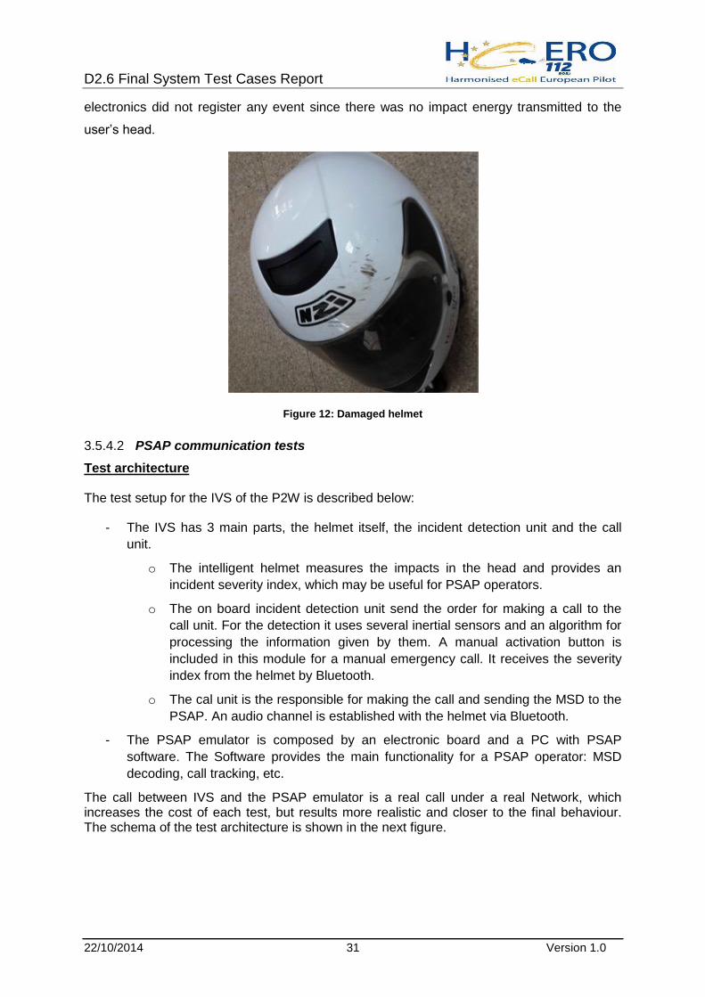
The second incident was caused by pilot inattention on a curve. Bike expelled the rider
above the handlebar and felt down impacting with the head on the floor. The impacted floor
was a gravel trap. Helmet shell and visor were scratched. NZI dismantled the helmet and
analysed the protective padding. Protective padding was not affected at all, showing that
there were not damages than outer scratches to the shell. The helmet impact detection
D2.6 Final System Test Cases Report
22/10/2014 31 Version 1.0
electronics did not register any event since there was no impact energy transmitted to the
user’s head.
Figure 12: Damaged helmet
PSAP communication tests 3.5.4.2
Test architecture
The test setup for the IVS of the P2W is described below:
- The IVS has 3 main parts, the helmet itself, the incident detection unit and the call
unit.
o The intelligent helmet measures the impacts in the head and provides an
incident severity index, which may be useful for PSAP operators.
o The on board incident detection unit send the order for making a call to the
call unit. For the detection it uses several inertial sensors and an algorithm for
processing the information given by them. A manual activation button is
included in this module for a manual emergency call. It receives the severity
index from the helmet by Bluetooth.
o The cal unit is the responsible for making the call and sending the MSD to the
PSAP. An audio channel is established with the helmet via Bluetooth.
- The PSAP emulator is composed by an electronic board and a PC with PSAP
software. The Software provides the main functionality for a PSAP operator: MSD
decoding, call tracking, etc.
The call between IVS and the PSAP emulator is a real call under a real Network, which increases the cost of each test, but results more realistic and closer to the final behaviour. The schema of the test architecture is shown in the next figure.

D2.6 Final System Test Cases Report
22/10/2014 32 Version 1.0
Figure 13: P2W Test architecture
Figure 14: P2W with IVS installed
Incident call +MSD PSAP emulator
Incident
Severity
Index
Voic

D2.6 Final System Test Cases Report
22/10/2014 33 Version 1.0
Test results
The test results can be shown in the next table, where calls has been divided in successful
calls (OK), Failed Calls and other where the voice connection has been established, but with
some errors in the MSD, usually related to positioning.
Type of call Total Calls OK Failed Calls Connected with MSD error
Manual 40 39 (97.5%) 0 (0%) 1 (2.5%)
Automatic 40 38 (95.0%) 0 (0%) 2 (5.0%)
Total 80 77 (96.25%) 0 (0%) 3 (3.75%)
Table 4 eCall P2W Test Results
3.6 Turkey
3.6.1 Mobile network
There are three mobile network operators in Turkey: TURKCELL, VODAFONE and AVEA. In
the Turkish pilot, eCall flag was implemented and tested only on TURKCELL network in
Antalya. There was no need for additional HW but a new SW had to be implemented on the
TURKCELL side. TURKCELL’s current test system in Istanbul was used for eCall flag related
IVS-MNO-PSAP integration tests, before field tests took place in Antalya.
TURKCELL uses ERICSSON switches in their infrastructure. In order to route the eCall
flagged emergency calls to the related eCall PSAP, new switch configuration was
implemented. SW updates and configurations were performed for this purpose.
3.6.2 IVS
Two types of eCall IVS equipment was used in the Turkish pilot; one from Civitronic
(RENAULT) and another one from Magneti Marelli (TOFAŞ).
Installations were done in four vehicles. Two vehicles were equipped with Civitronic devices;
the other two were equipped with Magneti Marelli devices.
RENAULT and TOFAŞ were responsible for the installation.
Both RENAULT and TOFAŞ tested manual eCalls.
3.6.3 PSAP
Tasks that were realized during the pilot project implementation:
A) Call centre part

D2.6 Final System Test Cases Report
22/10/2014 34 Version 1.0
Integration of PSAP in-band modem into the ASELSAN’s PSAP solution
Checking and handover of MSD information into the operator’s call taker
application
Checking voice connection with the vehicle
B) Application part
MSD handling
Presentation and visualization of MSD in call taker application
Visualization of incident location in GIS
Voice connection with the vehicle
Statistics and testing related developments in call taker application
3.6.4 Fixed Network Operator
Tasks that were realized during the pilot project implementation:
A) Interconnection of ASELSAN and TURKCELL test systems
a) Related hardware (ISDN PRI) installation
b) Routings and related network configuration
B) Interconnection of eCall PSAP with FNO network
a) Related hardware (ISDN PRI) installation
b) Routings and related network configuration
c) Routing of eCalls to the eCall PSAP
D2.6 Final System Test Cases Report
22/10/2014 35 Version 1.0
4 Implementation Results
During the project runtime the six WP2 Coordinators from the Member States regularly
updated a table with their implementation status. The table was created in August 2013 after
the regular implementation phase was finished. It was updated when the tests should have
been started according to the schedule. And it was updated again to create this document.
4.1 IVS Implementation
The IVS section of the Implementation Status was divided into three parts:
Information: General information about the device, the vendor (mostly their part of
the project), the model number and the number of installed devices.
Installation process contains information about the availability (some partners were
still developing their IVS’s when the project had started), about the actual installation
date and the installation mode (integrated or removable)
Initial testing showed if and when the IVS was tested and was ready for the
following HeERO test suite
In HeERO2 a total of 55 devices from 13 different vendors have been used for testing. Six of
them were integrated in the car, the other ones were removable. One device was designed
for the after-market in November 2013 85% of the devices was ready and installed. At the
scheduled start of testing 95% were ready. The latest tests have been performed with all
(100%) of the devices enabled. Thus test results will show the complete range of IVS.
4.2 PSAP Implementation
The PSAP implementation was a more centric part of the work in HeERO2. In addition to this
the partners have selected different ways of implementing eCall in their PSAP infrastructure,
so results are not as comparable as in the IVS section.
The PSAP section of the Implementation Status was divided into four parts:
PSAP Location (self-explaining)
Decision process: We knew from the first HeERO project that this was an
underestimated part of the project – decision and procurement took much longer than
primarily predicted. This is more a question of the political and financial decision
process than of the technical decision itself. So this part was much more on the focus

D2.6 Final System Test Cases Report
22/10/2014 36 Version 0.1
of the WP2 coordinator than before. In this part of the table the partners should fill in
their choice of system, the current status of their procurement process, the eCall
System Manufacturer and finally the (predicted) date of process termination.
The Installation process covered the eCall system installation itself, the interfaces to
the PBX and to the PSAP software and the (predicted) date of process termination.
Initial testing showed if and when the PSAP installation was tested and was ready
for the following HeERO test suite.
In HeERO2 a total of 13 PSAPs (with alone 5 in Spain) were upgraded and eCall-enabled. In
addition Belgium implemented a “filtering instance”, which was the first time this way of eCall
implementation was realised. It was also the first time the EN16102 interface definition was
ever used for eCall MSD transmission.
In November 2013 only 70% of the PSAPs were ready for testing, but all Member States had
at least one eCall-enabled PSAP in the starting blocks. The other PSAPs joined the tests one
after the other. In October 2014 the Belgium Filtering Instance passed the final tests (but had
been already online since March 2014).
Most of the partners used PSAP extensions already available on the market, which had
grown since the first HeERO project. Using these products made it much easier to upgrade
the PSAPs. Once a member state had finished the procurement process, the technical
upgrade was established very soon. Integration into the existing PSAP software is only
completed in some Member States, but this was not a mandatory objective anyhow. Some
MS have decided to update the complete software system later than 2014 and delayed the
eCall integration according to their schedule.
4.3 MNO Implementation
Mobile Network Providers have to setup the eCall discriminator flag into their systems. Once
this is only a minor software setup, but instead of attaching IVS devices to cars or to add
eCall technology to PSAPs, this step means to exchange a vital part of the operational
Mobile Network. Thus the MNOs are quite hesitant implementing this addition to their
network. It has to be integrated into their software enrolment plan.
In HeERO2 we find the same situation as in the earlier HeERO project. Some Member
States – mostly those with MNOs directly involved in the project – have enabled at least one
network with the eCall Flag. Other Member States have advised a Mobile Network with the
eCall flag at the start of the project, but at the end of 2014 the networks are still working with
D2.6 Final System Test Cases Report
22/10/2014 37 Version 1.0
non-eCall-flag software. Some partners tested their equipment under a special environment
or a work-around. So the result for this part of the implementation is only mixed. Fortunately
all MNOs have scheduled the eCall flag implementation until 2016.