d2.2 measurement procedures specification · 2017-05-19 · satellite technology for advanced...
TRANSCRIPT
This project has received funding from the European Union’s Horizon 2020 research and innovation program under grant agreement No. 687414
D2.2 Measurement Procedures Specification
Project acronym: STARS
Project full title: Satellite Technology for Advanced Railway Signalling
EC Contract No.: (H2020) 687414
Version of the document: 07
Protocol code: STR-WP2-D-ANS-047
Responsible partner: ANSALDO
Reviewing status: Issued
Delivery date: 15/12/16
Dissemination level: PUBLIC
SATELLITE TECHNOLOGY FOR ADVANCED RAILWAY SIGNALLING
STR-WP2-D-ANS-047-07 Page 2 of 59
CHANGE RECORDS
Version Date Changes Authors
01 31.06.16 First draft
N. Kassabian (ASTS), P. Kačmařík, (AŽD), L. Bažant (AŽD), A. Pazos (SIE), O. Richter (SIE), H. Ibendorf (SIE)
02 11.10.16 Updated chapter 2, extended Ground Truth information in section 2.3.1 and updated chapter 3, elaborated on chapter 4 and 5
N. Kassabian (ASTS), P. Kačmařík, (AŽD), L. Bažant (AŽD), A. Pazos (SIE), O. Richter (SIE), H. Ibendorf (SIE)
03 18.10.16 Implemented changes based on comments of WP2 member review
N. Kassabian (ASTS)
04 09.11.16 Included modifications according to WP2 members review and TMT review
N. Kassabian (ASTS)
05 30.11.16 Updated TBD and yellow entries and removed chapter 4 skeleton
N. Kassabian (ASTS)
06 15.12.16
Removed typo, empty section 3.1.4 entitled procedures related to data storage servers is related to post measurement campaign and will be clarified in WP3 and WP4
N. Kassabian (ASTS)
07 15.12.16 Final version after TMT approval A. Toma (DAPP)
SATELLITE TECHNOLOGY FOR ADVANCED RAILWAY SIGNALLING
STR-WP2-D-ANS-047-07 Page 3 of 59
TABLE OF CONTENTS
CHANGE RECORDS ...................................................................................................................... 2
1 INTRODUCTION ...................................................................................................................... 7
1.1 Executive summary .......................................................................................................... 7
1.2 Definitions and acronyms ................................................................................................. 7
2 MEASUREMENT EQUIPMENT AND MEASUREMENT DATA SYNCHRONISATION .......... 10
2.1 Measuring Equipment Arrangement ............................................................................... 10
2.1.1 Centralised measurement system .............................................................................................. 10
2.1.2 Distributed measurement system ............................................................................................... 11
2.2 Performance and Specifications of Standardised Equipment for GNSS Performance Assessment ............................................................................................................................... 19
2.2.1 GNSS/wideband antennas ......................................................................................................... 19
2.2.2 GNSS/SBAS Receivers .............................................................................................................. 20
2.2.3 GNSS RPS ................................................................................................................................. 22
2.2.4 Spectrum Analyser or high frequency digitizers ......................................................................... 22
2.2.5 Panoramic Camera for sky visibility ............................................................................................ 23
2.2.6 Description of Time Synchronisation Possibilities ...................................................................... 23
2.2.7 Reference Clock Source ............................................................................................................. 24
2.2.8 Data acquisition computer .......................................................................................................... 24
2.3 Techniques for assessment of GNSS position error ....................................................... 24
2.3.1 Performance of GT ..................................................................................................................... 24
2.3.2 GNSS position estimation ........................................................................................................... 29
2.3.3 GNSS position error estimation with respect to GT .................................................................... 31
2.3.4 GNSS position error assessment with GNSS dependent position reference ............................. 38
2.3.5 GNSS position error assessment based on particular GNSS signal quality and satellite geometry ................................................................................................................................................... 43
2.4 Performance and Specifications of Individual Line Equipment Mainly For GT Assessment 43
2.4.1 Eurobalise /Balise Transmission Module .................................................................................... 43
2.4.2 Magnetic Identification Balise (MIB) ........................................................................................... 43
2.4.3 Wheel Tachometer ..................................................................................................................... 44
2.4.4 RFID ............................................................................................................................................ 44
2.4.5 Optical Encoder .......................................................................................................................... 44
2.4.6 Doppler Radar Speedometer ...................................................................................................... 45
2.5 Railway Line Managed by ASTS .................................................................................... 46
2.6 Railway Line Managed by SIE ....................................................................................... 46
2.7 Railway Lines Managed by AZD .................................................................................... 46
3 MEASUREMENT PROCEDURES PRELIMINARY OPERATIONAL CONCEPT ................... 47
SATELLITE TECHNOLOGY FOR ADVANCED RAILWAY SIGNALLING
STR-WP2-D-ANS-047-07 Page 4 of 59
3.1 Measurement Acquisition ............................................................................................... 47
3.1.1 Procedures related to Time Synchronisation .............................................................................. 48
3.1.2 Procedures related to Real Time Processor ............................................................................... 48
3.1.3 Procedures related to data Acquisition Computer ...................................................................... 48
3.1.4 Data Format ................................................................................................................................ 48
3.1.5 Naming Conventions .................................................................................................................. 48
3.2 Procedures Related to Test Specific Data ...................................................................... 50
3.2.1 Test Vehicle Identification ........................................................................................................... 50
3.2.2 Test Track Identification .............................................................................................................. 51
3.2.3 Test Environment Conditions ...................................................................................................... 51
3.2.4 Weather Conditions .................................................................................................................... 51
3.2.5 Geo-referencing Considerations ................................................................................................. 51
3.2.6 GNSS Service Performance Forecast for Campaign Scheduling .............................................. 52
3.3 Procedures Related to Standardised Equipment for GNSS Performance Assessment .. 52
3.3.1 GNSS antennas .......................................................................................................................... 52
3.3.2 RF splitters .................................................................................................................................. 52
3.3.3 GNSS/SBAS receivers ............................................................................................................... 52
3.3.4 Spirent GNSS RPS or RF signal recorder .................................................................................. 52
3.3.5 VSA or Modern Real Time Spectrum Analyser Recorder .......................................................... 53
3.3.6 Camera or Video recorder .......................................................................................................... 54
3.4 Procedures Related to EGNOS Data ............................................................................. 54
3.4.1 EDAS Service ............................................................................................................................. 54
3.4.2 Access to EDAS service ............................................................................................................. 54
3.4.3 Data to be retrieved from EDAS service ..................................................................................... 55
3.4.4 Other parameters ........................................................................................................................ 55
3.5 Procedures Related to Individual Line Equipment for GT Assessment ........................... 56
3.5.1 Procedures related to Track Database ....................................................................................... 56
3.5.2 Procedures related to Eurobalises.............................................................................................. 56
3.5.3 Procedures related to Magnetic Identification Balise (MIB) ........................................................ 56
3.5.4 Procedures related to tachometer at wheel / rail system............................................................ 56
3.5.5 Procedures related to Optical Correlation Sensor ...................................................................... 57
3.5.6 Procedures related to Doppler radar sensor .............................................................................. 58
4 REFERENCES ....................................................................................................................... 59
SATELLITE TECHNOLOGY FOR ADVANCED RAILWAY SIGNALLING
STR-WP2-D-ANS-047-07 Page 5 of 59
LIST OF FIGURES
Figure 1: Centralised measurement system: set-up of sensors and real-time processor for time stamping (Eurobalise, optical encoder, wheel tachometer and GNSS receiver as a time reference) ............................................................................................................................... 10
Figure 2: Distributed measurement system: the system is divided into several autonomous sub-systems. The central part, the supervision processor, should ensure mainly controlling of sub-system (watch-dog feature) and remote access to the system but no synchronisation. The synchronisation is ensured with time-stamping to GPST individually (or to GPST provided form GNSS RX sub-system). .......................................................................................................... 11
Figure 3: SBF messages over time................................................................................................ 21
Figure 4: Key performance parameters of a ground truth system .................................................. 25
Figure 5: Ground Truth measurement scenarios ........................................................................... 27
Figure 6: Track Discrimination Scenario ........................................................................................ 28
Figure 7: Relationship between real train position, estimated GT, GNSS antenna location, and computed GNSS position (PVT) ............................................................................................. 38
Figure 8: Wheel tachometer mounted at cover at end of axis ........................................................ 57
Figure 9: Optical correlation sensor mounted at bogie of ICE1 ...................................................... 58
Figure 10: Placement conditions and SRRIII installation at ICE1 ................................................... 58
SATELLITE TECHNOLOGY FOR ADVANCED RAILWAY SIGNALLING
STR-WP2-D-ANS-047-07 Page 6 of 59
LIST OF TABLES
Table 1: Possible set of Measurement Equipment to be utilized in Measurement System of different trial sites ................................................................................................................................. 18
Table 2: GNSS/wideband Antennas .............................................................................................. 20
Table 3: GNSS/SBAS Receivers ................................................................................................... 21
Table 4: GNSS RPS ...................................................................................................................... 22
Table 5: Spectrum Analysers......................................................................................................... 22
Table 6: Panoramic Camera .......................................................................................................... 23
Table 7: Ground Truth requirements for different objectives .......................................................... 26
Table 8: GNSS position estimation techniques .............................................................................. 30
Table 9: GNSS PE estimation techniques relative to GNSS independent GT ................................ 37
Table 10: GNSS position error assessment with GNSS dependent reference position .................. 42
Table 11: Accuracy and Price of different optical encoders ........................................................... 45
Table 12: Measurement Acquisition aspects ................................................................................. 48
SATELLITE TECHNOLOGY FOR ADVANCED RAILWAY SIGNALLING
STR-WP2-D-ANS-047-07 Page 7 of 59
1 INTRODUCTION
1.1 EXECUTIVE SUMMARY
The purpose of this document is to present the results of all information collected by WP2 members for the definition of the procedures related to the STARS WP2 measurement campaign. This is related with the task 2.2 defined at the WP2 project planning. It should also be taken into consideration that the decisions taken in WP2 are linked to the future development of WP3 and WP4.
Chapter 2 lists the set of measurement equipment for GNSS performance assessment as well as techniques for Ground Truth estimation. Chapter 3 discusses the main aspects of the measurement acquisition system, and the procedures related to the measurement equipment to be deployed on the railway lines.
1.2 DEFINITIONS AND ACRONYMS
Acronym Meaning
AC Alternate Current
ADC Analog to Digital Converter
ARM Absolute Reference Measurement
BTM Balise Transmission Module
CMC Code Minus Carrier
COTS Commercial Off The Shelf
DC Direct Current
EDAS EGNOS Data Access Service
EGNOS European Geostationary Navigation Overlay System
EKF Extended Kalman Filter
EMC ElectroMagnetic Compatibility
ETCS European Train Control System
FE Front End
FFFIS Form Fit Functional Interface Specification
FTP File Transfer Protocol
GDOP Geometric Dilution Of Precision
GEO Geostationary Earth Orbit
GNSS Global Navigation Satellite System
SATELLITE TECHNOLOGY FOR ADVANCED RAILWAY SIGNALLING
STR-WP2-D-ANS-047-07 Page 8 of 59
GT Ground Truth
GPST GPS Time
HDOP Horizontal Dilution Of Precision
IF Intermediate Frequency
IGS International GNSS Service
IMU Inertial Measurement Unit
LHCP Left Hand Circular Polarisation
LNA Low Noise Amplifier
LOS Line Of Sight
MCMF Multiple Constellation Multiple Frequency
MCSF Multiple Constellation Single Frequency
MDB Minimum Detectable Bias
MIB Magnetic Identification Balise
MP MultiPath
NLOS Non-Line Of Sight
NTP Network Time Protocol
OCXO Oven Controlled Crystal Oscillator
PE Position Error
PDOP Position Dilution Of Precision
PPD Personal Privacy Devices
PPK Post-processed Kinematic
PPSDK Post Processing Software Development Kit
PSD Power Spectral Density
PVT Position, Velocity, Time
RAIM Receiver Autonomous Integrity Monitoring
RDM Relative Distance Measurement
RF Radio Frequency
SATELLITE TECHNOLOGY FOR ADVANCED RAILWAY SIGNALLING
STR-WP2-D-ANS-047-07 Page 9 of 59
RFI Radio Frequency Interference
RFID Radio Frequency Identification Device
RHCP Right Hand Circular Polarisation
RMS Root Mean Square
RPS Record and Playback System
RTK Real Time Kinetic
RTSA Real Time Spectrum Analyser
RX Receiver
SBAS Satellite Based Augmentation System
SBF Septentrio Binary Format
SDD Service Definition Document
SNR Signal to Noise Ratio
SSD Solid State Drive
SW Software
TDOP Time Dilution Of Precision
URE User Range Error
VDOP Vertical Dilution Of Precision
VSA Vector Signal Analyser
WLS Weighted Least Squares
SATELLITE TECHNOLOGY FOR ADVANCED RAILWAY SIGNALLING
STR-WP2-D-ANS-047-07 Page 10 of 59
2 MEASUREMENT EQUIPMENT AND MEASUREMENT DATA
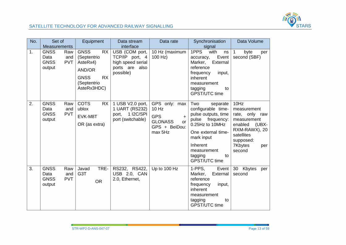
SYNCHRONISATION Based on the list of the measurements to be collected in D2.1 [4], this chapter proposes the type of instrumentation and measurements needed to cover various aspects of GNSS signal acquisition in the railway environment. The related interface of these instruments together with synchronisation capability, data rate and data volume are described in Table 1.
In essence, the core of the measurements is related to:
1. GNSS Raw Data (code and carrier phase measurements)
2. GNSS PVT output from sample receivers
3. GNSS RF samples (either at IF frequency or baseband)
4. In-band and out-of-band interference measurements
5. Environment related measurements (sky visibility, foliage, buildings…)
6. Train estimated position in 3D coordinates (Speed, distance, time stamp, accuracy and
confidence level of measurements) - where confidence level expresses the accuracy in
terms of trueness and precision as depicted in Figure 4.
2.1 MEASURING EQUIPMENT ARRANGEMENT
2.1.1 Centralised measurement system
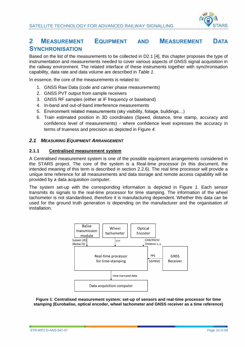
A Centralised measurement system is one of the possible equipment arrangements considered in the STARS project. The core of the system is a Real-time processor (in this document, the intended meaning of this term is described in section 2.2.6). The real time processor will provide a unique time reference for all measurements and data storage and remote access capability will be provided by a data acquisition computer.
The system set-up with the corresponding information is depicted in Figure 1. Each sensor transmits its signals to the real-time processor for time stamping. The information of the wheel tachometer is not standardised, therefore it is manufacturing dependent. Whether this data can be used for the ground truth generation is depending on the manufacturer and the organisation of installation.
Figure 1: Centralised measurement system: set-up of sensors and real-time processor for time stamping (Eurobalise, optical encoder, wheel tachometer and GNSS receiver as a time reference)
SATELLITE TECHNOLOGY FOR ADVANCED RAILWAY SIGNALLING
STR-WP2-D-ANS-047-07 Page 11 of 59
2.1.2 Distributed measurement system
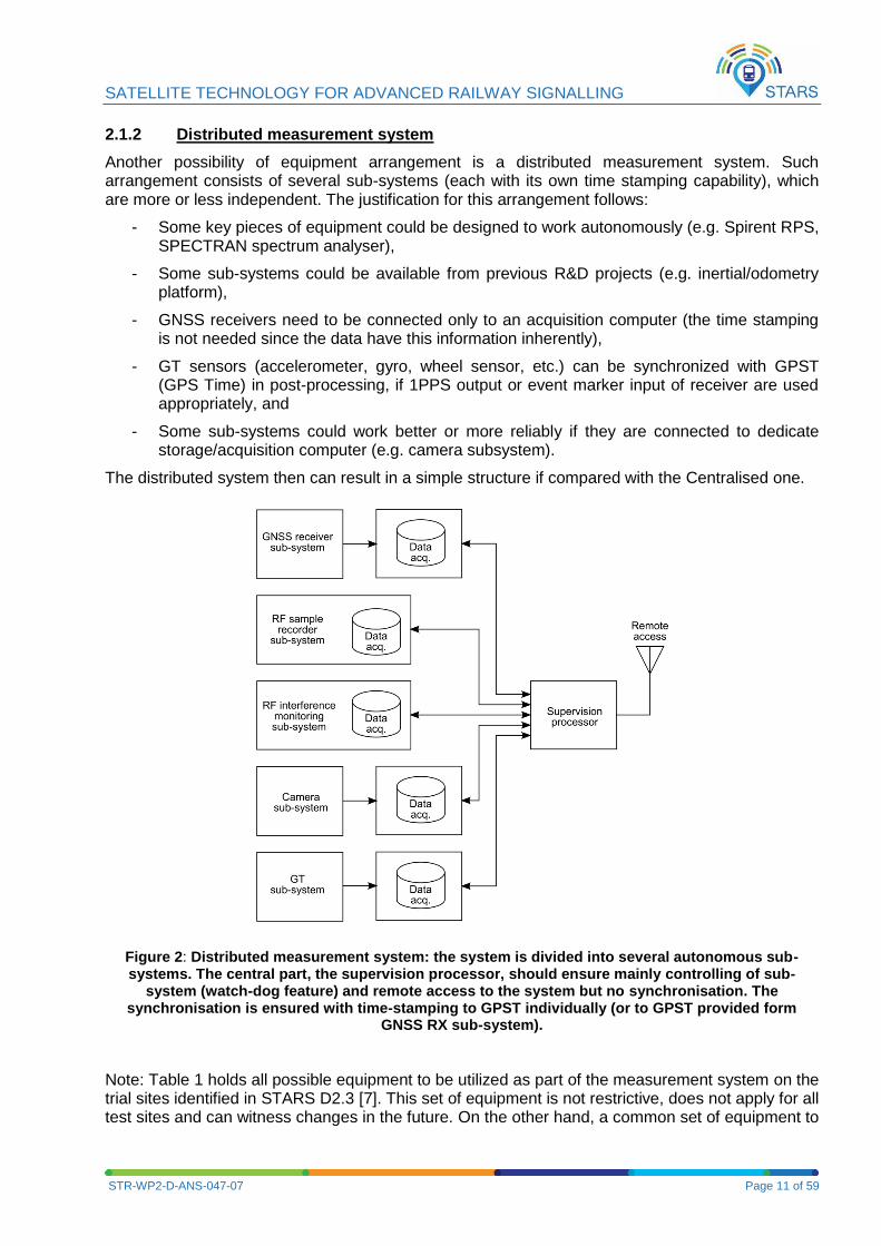
Another possibility of equipment arrangement is a distributed measurement system. Such arrangement consists of several sub-systems (each with its own time stamping capability), which are more or less independent. The justification for this arrangement follows:
- Some key pieces of equipment could be designed to work autonomously (e.g. Spirent RPS, SPECTRAN spectrum analyser),
- Some sub-systems could be available from previous R&D projects (e.g. inertial/odometry platform),
- GNSS receivers need to be connected only to an acquisition computer (the time stamping is not needed since the data have this information inherently),
- GT sensors (accelerometer, gyro, wheel sensor, etc.) can be synchronized with GPST (GPS Time) in post-processing, if 1PPS output or event marker input of receiver are used appropriately, and
- Some sub-systems could work better or more reliably if they are connected to dedicate storage/acquisition computer (e.g. camera subsystem).
The distributed system then can result in a simple structure if compared with the Centralised one.
Figure 2: Distributed measurement system: the system is divided into several autonomous sub-systems. The central part, the supervision processor, should ensure mainly controlling of sub-
system (watch-dog feature) and remote access to the system but no synchronisation. The synchronisation is ensured with time-stamping to GPST individually (or to GPST provided form
GNSS RX sub-system).
Note: Table 1 holds all possible equipment to be utilized as part of the measurement system on the trial sites identified in STARS D2.3 [7]. This set of equipment is not restrictive, does not apply for all test sites and can witness changes in the future. On the other hand, a common set of equipment to
SATELLITE TECHNOLOGY FOR ADVANCED RAILWAY SIGNALLING
STR-WP2-D-ANS-047-07 Page 12 of 59
be used on the three test sites have been identified in [8]. In addition, detailed technical information is provided in [8] for the motivation behind the use of such measurement equipment.
SATELLITE TECHNOLOGY FOR ADVANCED RAILWAY SIGNALLING
STR-WP2-D-ANS-047-07 Page 13 of 59
No. Set of Measurements
Equipment Data stream interface
Data rate Synchronisation signal
Data Volume
1. GNSS Raw Data and GNSS PVT output
GNSS RX (Septentrio AsteRx4)
AND/OR
GNSS RX (Septentrio AsteRx3HDC)
USB (COM port, TCP/IP port, 4 high speed serial ports are also possible)
10 Hz (maximum 100 Hz)
1PPS with ns accuracy, Event Marker, External reference frequency input, inherent measurement tagging to GPST/UTC time
1 byte per second (SBF)
2. GNSS Raw Data and GNSS PVT output
COTS RX ublox
EVK-M8T
OR (as extra)
1 USB V2.0 port, 1 UART (RS232) port, 1 I2C/SPI port (switchable)
GPS only: max 10 Hz
GPS + GLONASS or GPS + BeiDou: max 5Hz
Two separate configurable time-pulse outputs, time pulse frequency: 0.25Hz to 10MHz
One external time-mark input
Inherent measurement tagging to GPST/UTC time
10Hz measurement rate, only raw measurement enabled (UBX-RXM-RAWX), 20 satellites supposed: 7Kbytes per second
3. GNSS Raw Data and GNSS PVT output
Javad TRE-G3T
OR
RS232, RS422, USB 2.0, CAN 2.0, Ethernet,
Up to 100 Hz 1-PPS, Event Marker, External reference frequency input, inherent measurement tagging to GPST/UTC time
30 Kbytes per second
SATELLITE TECHNOLOGY FOR ADVANCED RAILWAY SIGNALLING
STR-WP2-D-ANS-047-07 Page 14 of 59
No. Set of Measurements
Equipment Data stream interface
Data rate Synchronisation signal
Data Volume
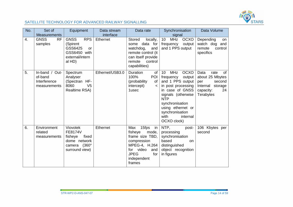
4. GNSS RF samples
GNSS RPS (Spirent GSS6425 or GSS6450 with external/internal HD)
Ethernet Stored locally, some data for watchdog, and remote control (it can itself provide remote control capabilities)
10 MHz OCXO frequency output and 1 PPS output
Depending on watch dog and remote control specifics
5. In-band / Out-of-band Interference measurements
Spectrum Analyser (Spectran HF-8060 V5 Realtime RSA)
Ethernet/USB3.0 Duration of 100% POI (probability of intercept) < 1usec
10 MHz OCXO frequency output and 1 PPS output in post processing in case of GNSS signals (otherwise NTP synchronisation using ethernet or synchronisation with internal OCXO clock)
Data rate of about 25 Mbytes per second Internal storage capacity: 24 Terabytes
6. Environment related measurements
Viovotek FE8174V fisheye fixed dome network camera (360° surround view)
Ethernet Max 15fps in fisheye mode, frame size TBD, compression MPEG-4, H.264 for video and JPEG for independent frames
NTP, post-processing synchronisation based on distinguished object recognition in figures
106 Kbytes per second
SATELLITE TECHNOLOGY FOR ADVANCED RAILWAY SIGNALLING
STR-WP2-D-ANS-047-07 Page 15 of 59
No. Set of Measurements
Equipment Data stream interface
Data rate Synchronisation signal
Data Volume
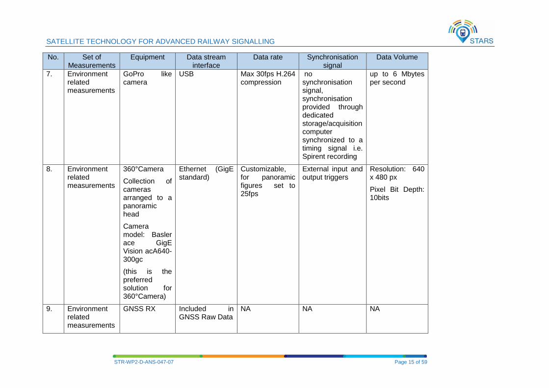
7. Environment related measurements
GoPro like camera
USB Max 30fps H.264 compression
no synchronisation signal, synchronisation provided through dedicated storage/acquisition computer synchronized to a timing signal i.e. Spirent recording
up to 6 Mbytes per second
8. Environment related measurements
360°Camera
Collection of cameras arranged to a panoramic head
Camera model: Basler ace GigE Vision acA640-300gc
(this is the preferred solution for 360°Camera)
Ethernet (GigE standard)
Customizable, for panoramic figures set to 25fps
External input and output triggers
Resolution: 640 x 480 px
Pixel Bit Depth: 10bits
9. Environment related measurements
GNSS RX Included in GNSS Raw Data
NA NA NA
SATELLITE TECHNOLOGY FOR ADVANCED RAILWAY SIGNALLING
STR-WP2-D-ANS-047-07 Page 16 of 59
No. Set of Measurements
Equipment Data stream interface
Data rate Synchronisation signal
Data Volume
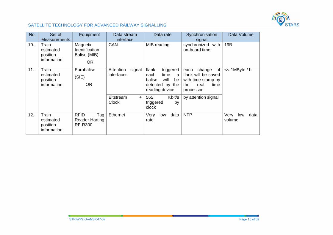
10. Train estimated position information
Magnetic Identification Balise (MIB)
OR
CAN MIB reading synchronized with on-board time
19B
11. Train estimated position information
Eurobalise
(SIE)
OR
Attention signal interfaces
flank triggered each time a balise will be detected by the reading device
each change of flank will be saved with time stamp by the real time processor
<< 1MByte / h
Bitstream + Clock
565 Kbit/s triggered by clock
by attention signal
12. Train estimated position information
RFID Tag Reader Harting RF-R300
Ethernet Very low data rate
NTP Very low data volume
SATELLITE TECHNOLOGY FOR ADVANCED RAILWAY SIGNALLING
STR-WP2-D-ANS-047-07 Page 17 of 59
No. Set of Measurements
Equipment Data stream interface
Data rate Synchronisation signal
Data Volume
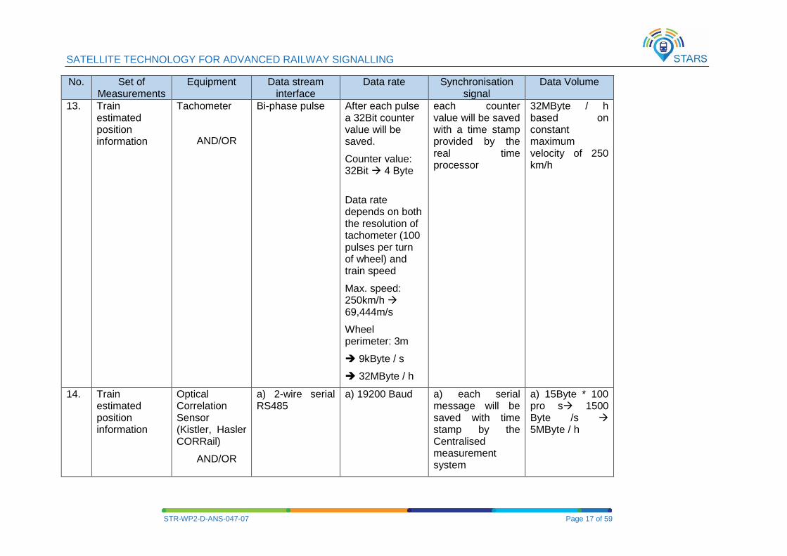
13. Train estimated position information
Tachometer
AND/OR
Bi-phase pulse After each pulse a 32Bit counter value will be saved.
Counter value: 32Bit 4 Byte
Data rate depends on both the resolution of tachometer (100 pulses per turn of wheel) and train speed
Max. speed: 250km/h 69,444m/s
Wheel perimeter: 3m
9kByte / s
32MByte / h
each counter value will be saved with a time stamp provided by the real time processor
32MByte / h based on constant maximum velocity of 250 km/h
14. Train estimated position information
Optical Correlation Sensor (Kistler, Hasler CORRail)
AND/OR
a) 2-wire serial RS485
a) 19200 Baud
a) each serial message will be saved with time stamp by the Centralised measurement system
a) 15Byte * 100 pro s 1500 Byte /s 5MByte / h
SATELLITE TECHNOLOGY FOR ADVANCED RAILWAY SIGNALLING
STR-WP2-D-ANS-047-07 Page 18 of 59
No. Set of Measurements
Equipment Data stream interface
Data rate Synchronisation signal
Data Volume
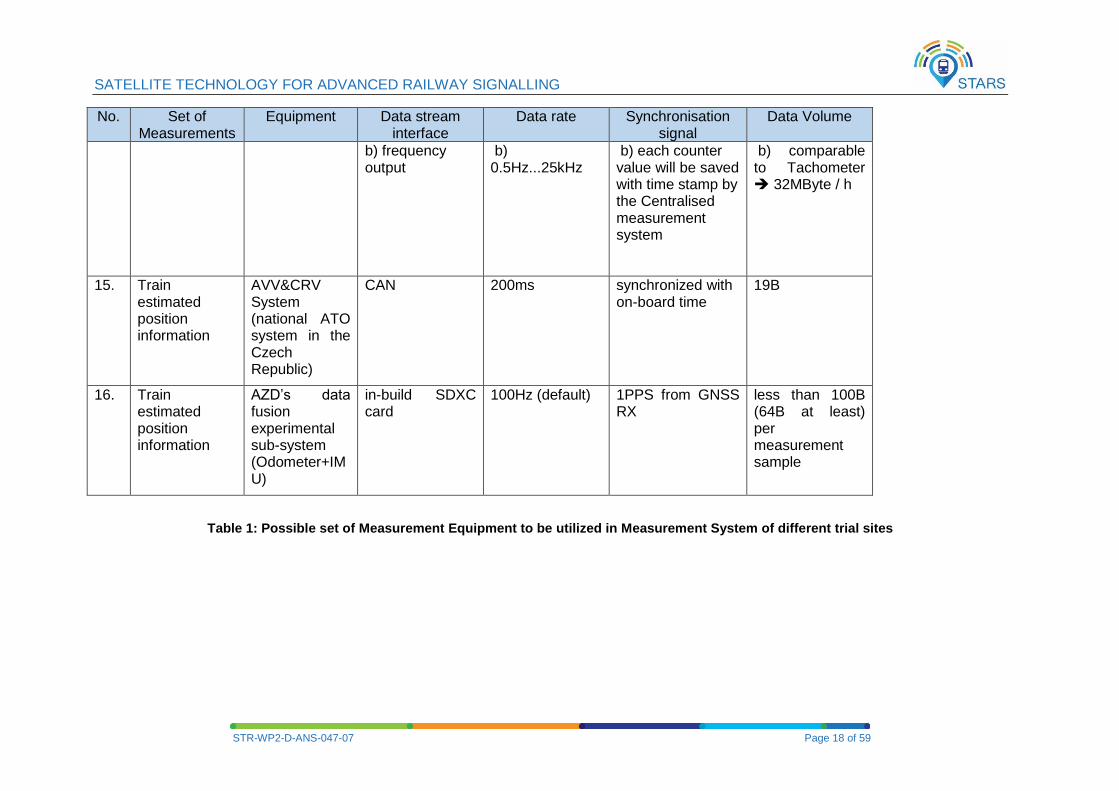
b) frequency output
b) 0.5Hz...25kHz
b) each counter value will be saved with time stamp by the Centralised measurement system
b) comparable to Tachometer 32MByte / h
15. Train estimated position information
AVV&CRV System (national ATO system in the Czech Republic)
CAN 200ms synchronized with on-board time
19B
16. Train estimated position information
AZD’s data fusion experimental sub-system (Odometer+IMU)
in-build SDXC card
100Hz (default) 1PPS from GNSS RX
less than 100B (64B at least) per measurement sample
Table 1: Possible set of Measurement Equipment to be utilized in Measurement System of different trial sites
SATELLITE TECHNOLOGY FOR ADVANCED RAILWAY SIGNALLING
STR-WP2-D-ANS-047-07 Page 19 of 59
Note: All sensors are pre-configured to send data in a continuous manner, equipment that need to be triggered to send data will be pointed out.
There will be an additional SW module that collects sensor data and database to convert in post-
processing the info into GT position in 3D coordinates.
It is planned that when applicable the data will be recorded in equipment specific format, which is usually a binary proprietary format. Before the data analysis in post-processing mode the data have to be converted to an appropriate format suitable for post-processing tools. A text format is supposed here. The reason for this choice is to save disk space in data acquisition computer(s) and also simplify the equipment setting (conversion will not be performed in real-time during the campaign).
Concerning GNSS receivers, apart from the RINEX format which is widely recognized standard for storing of raw data, binary files will be stored during the campaign (e.g. SBF for Septentrio, UBX for u-Blox). In addition to the mentioned reasons, the receiver’s binary formats can carry more information than RINEX format (e.g. information concerning actual multipath or RF interference is not supported in RINEX). Since such information is essential for STARS, such data shall be recorded in addition to RINEX data.
The specification of measurement information to be collected including RINEX version is found in [4]. On the other hand, the procedural guidelines to be followed on recording files are to use equipment specific format whenever possible, in addition to the RINEX format. Whenever this is not applicable, the conversion process from proprietary binary format to RINEX shall occur in post-processing.
2.2 PERFORMANCE AND SPECIFICATIONS OF STANDARDISED EQUIPMENT FOR GNSS
PERFORMANCE ASSESSMENT
The term standardised equipment used in this document is intended to indicate the same equipment that is adopted for all test lines considered in the STARS project. This equipment is mostly relative to GNSS signal performance assessment and is chosen to be similar in order to compare the results across different railway lines. Alternatively, similar equipment in terms of performance characteristics can be considered.
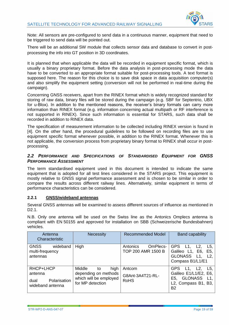
2.2.1 GNSS/wideband antennas
Several GNSS antennas will be examined to assess different sources of influence as mentioned in D2.1.
N.B. Only one antenna will be used on the Swiss line as the Antonics Omplecs antenna is compliant with EN 50155 and approved for installation on SBB (Schweizerische Bundesbahnen) vehicles.
Antenna Characteristic
Necessity Recommended Model Band capability
GNSS wideband multi-frequency antennas
High Antonics OmPlecs-TOP 200 AMR 1500 B
GPS L1, L2, L5, Galileo L1, E6, E5, GLONASS L1, L2, Compass B1/L1/E1
RHCP+LHCP antenna
dual Polarisation wideband antenna
Middle to high depending on methods which will be employed for MP detection
Antcom
G8Ant-3A4T21-RL-RoHS
GPS L1, L2, L5, Galileo E1/L1/E2, E6, E5, GLONASS L1, L2, Compass B1, B3, B2
SATELLITE TECHNOLOGY FOR ADVANCED RAILWAY SIGNALLING
STR-WP2-D-ANS-047-07 Page 20 of 59
Antenna Characteristic
Necessity Recommended Model Band capability
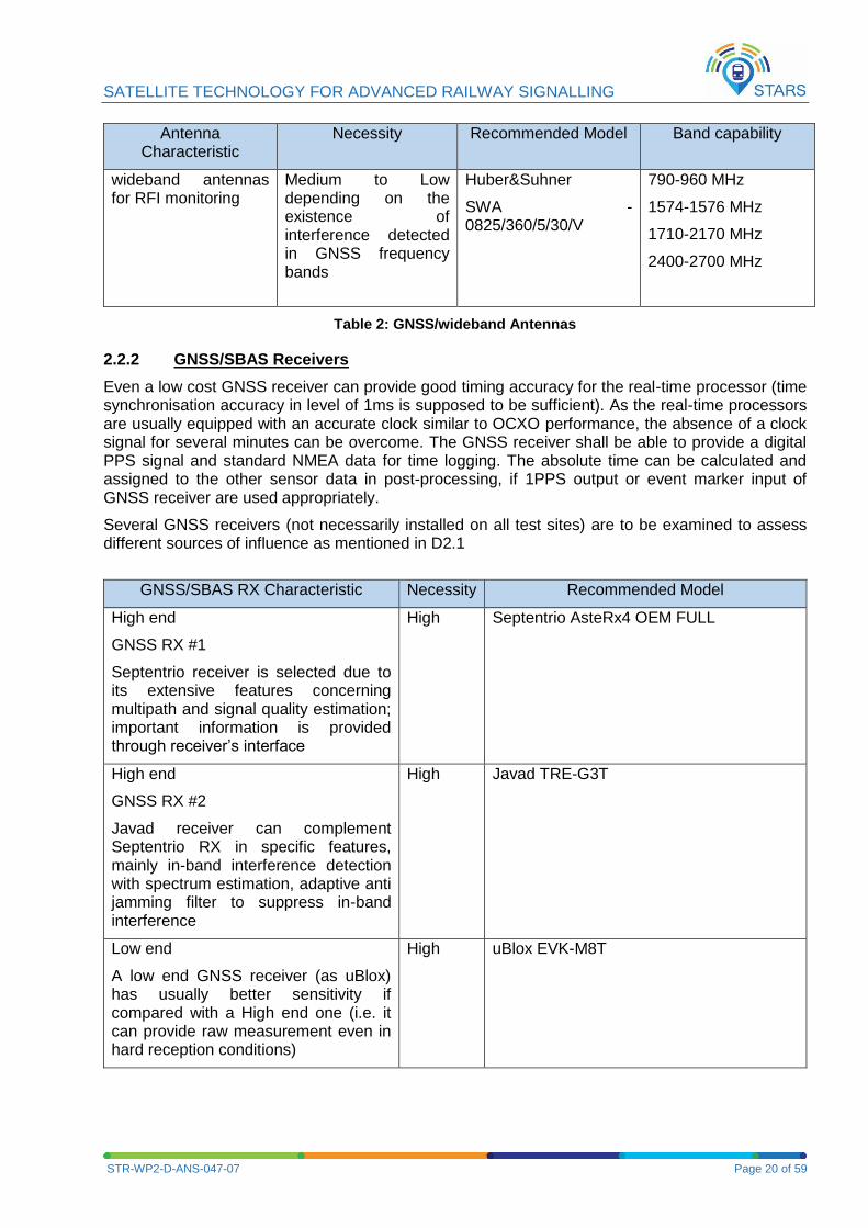
wideband antennas for RFI monitoring
Medium to Low depending on the existence of interference detected in GNSS frequency bands
Huber&Suhner
SWA - 0825/360/5/30/V
790-960 MHz
1574-1576 MHz
1710-2170 MHz
2400-2700 MHz
Table 2: GNSS/wideband Antennas
2.2.2 GNSS/SBAS Receivers
Even a low cost GNSS receiver can provide good timing accuracy for the real-time processor (time synchronisation accuracy in level of 1ms is supposed to be sufficient). As the real-time processors are usually equipped with an accurate clock similar to OCXO performance, the absence of a clock signal for several minutes can be overcome. The GNSS receiver shall be able to provide a digital PPS signal and standard NMEA data for time logging. The absolute time can be calculated and assigned to the other sensor data in post-processing, if 1PPS output or event marker input of GNSS receiver are used appropriately.
Several GNSS receivers (not necessarily installed on all test sites) are to be examined to assess different sources of influence as mentioned in D2.1
GNSS/SBAS RX Characteristic Necessity Recommended Model
High end
GNSS RX #1
Septentrio receiver is selected due to its extensive features concerning multipath and signal quality estimation; important information is provided through receiver’s interface
High Septentrio AsteRx4 OEM FULL
High end
GNSS RX #2
Javad receiver can complement Septentrio RX in specific features, mainly in-band interference detection with spectrum estimation, adaptive anti jamming filter to suppress in-band interference
High Javad TRE-G3T
Low end
A low end GNSS receiver (as uBlox) has usually better sensitivity if compared with a High end one (i.e. it can provide raw measurement even in hard reception conditions)
High uBlox EVK-M8T
SATELLITE TECHNOLOGY FOR ADVANCED RAILWAY SIGNALLING
STR-WP2-D-ANS-047-07 Page 21 of 59
GNSS/SBAS RX Characteristic Necessity Recommended Model
MCMF COTS GNSS Rx
PPSDK
Meteo sensor data included in SBF output (if connected to meteo sensor)
IMU sensor data included in SBF output (if connected to IMU sensor)
Septentrio AsteRx3HDC
Table 3: GNSS/SBAS Receivers
Septentrio AsteRx3HDC (or AsteRx4 OEM FULL) GNSS receiver
It can be connected to a PC via different interfaces:
- USB port
- Serial port,
- TCP/IP port,
It also accommodates for a meteo sensor and stores data in the SBF format.
It should be set appropriately to generate a pulse per second (PPS) that is aligned with either GPS, Galileo, GLONASS system time or with UTC. The interval between pulses can be set to 0.1, 0.2, 0.5, 1, 2, 5 or 10 seconds.
The recommended output format is SBF if it is desired to receive detailed information from the receiver. The benefit of SBF is compactness. The SBF converter tool can then convert the SBF data stream to RINEX, KML, GPX or ASCII.
It also gives indication of the signal quality in terms of RF input on a scale of 1 to 5
SBF data stream includes info on CPU load of the receiver which should stay below 80% in normal operation as higher loads may result in data loss.
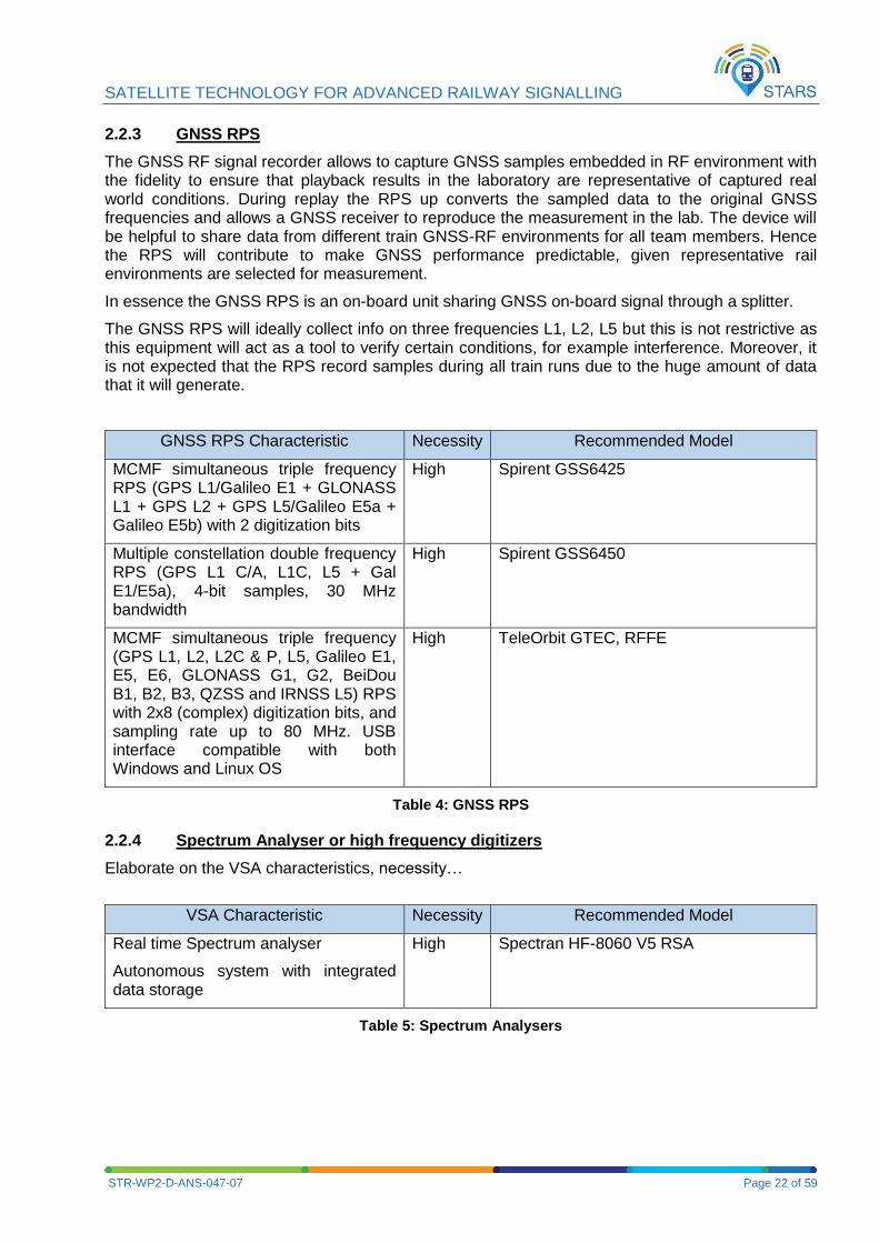
Below is a figure of SBF messages over time which includes all the measurements to be recorded as detailed in D2.1. It shows that not all data are outputted at every epoch (navigation data messages are outputted every time they are updated). In any case, it is possible to compute an average data rate of 5 byte/s with a desired 10 Hz output rate in terms of SBF data measurements (without IMU and meteo sensor data).
Figure 3: SBF messages over time
SATELLITE TECHNOLOGY FOR ADVANCED RAILWAY SIGNALLING
STR-WP2-D-ANS-047-07 Page 22 of 59
2.2.3 GNSS RPS
The GNSS RF signal recorder allows to capture GNSS samples embedded in RF environment with the fidelity to ensure that playback results in the laboratory are representative of captured real world conditions. During replay the RPS up converts the sampled data to the original GNSS frequencies and allows a GNSS receiver to reproduce the measurement in the lab. The device will be helpful to share data from different train GNSS-RF environments for all team members. Hence the RPS will contribute to make GNSS performance predictable, given representative rail environments are selected for measurement.
In essence the GNSS RPS is an on-board unit sharing GNSS on-board signal through a splitter.
The GNSS RPS will ideally collect info on three frequencies L1, L2, L5 but this is not restrictive as this equipment will act as a tool to verify certain conditions, for example interference. Moreover, it is not expected that the RPS record samples during all train runs due to the huge amount of data that it will generate.
GNSS RPS Characteristic Necessity Recommended Model
MCMF simultaneous triple frequency RPS (GPS L1/Galileo E1 + GLONASS L1 + GPS L2 + GPS L5/Galileo E5a + Galileo E5b) with 2 digitization bits
High Spirent GSS6425
Multiple constellation double frequency RPS (GPS L1 C/A, L1C, L5 + Gal E1/E5a), 4-bit samples, 30 MHz bandwidth
High Spirent GSS6450
MCMF simultaneous triple frequency (GPS L1, L2, L2C & P, L5, Galileo E1, E5, E6, GLONASS G1, G2, BeiDou B1, B2, B3, QZSS and IRNSS L5) RPS with 2x8 (complex) digitization bits, and sampling rate up to 80 MHz. USB interface compatible with both Windows and Linux OS
High TeleOrbit GTEC, RFFE
Table 4: GNSS RPS
2.2.4 Spectrum Analyser or high frequency digitizers
Elaborate on the VSA characteristics, necessity…
VSA Characteristic Necessity Recommended Model
Real time Spectrum analyser
Autonomous system with integrated data storage
High Spectran HF-8060 V5 RSA
Table 5: Spectrum Analysers
SATELLITE TECHNOLOGY FOR ADVANCED RAILWAY SIGNALLING
STR-WP2-D-ANS-047-07 Page 23 of 59
2.2.5 Panoramic Camera for sky visibility
Elaborate on panoramic camera characteristics, necessity…
Panoramic Camera Characteristic Necessity Recommended Model
IP Fisheye Network Camera
Camera internal time can be synchronized using NTP; in post-processing the data can be time tagged using distinguished objects in figures
High Vivotek FE8174
Commercial in-cabin solution
Low
GoPro or Samsung Gear 360 or 360fly Panoramic 360°
Table 6: Panoramic Camera
2.2.6 Description of Time Synchronisation Possibilities
As trains operate with high speeds, interface latency and sensor calculation time have a high impact on the confidence of the ground truth. This leads to the case that sensor data is not always recorded at the measured time by standard computers. Real-time processors buffer the collected data and transmit it to the data acquisition computer. One way to overcome this behaviour is to use a central real-time processor; another is to use several real-time processors and to align data in post-processing. In this way, all incoming data shall have a unique time reference.
A real-time processor is understood widely in this document, and not necessary represents a dedicated hardware component. Thus, the function of real-time processor can be implemented explicitly by hardware or software constituent or can be inherent part of specific equipment (sensor).
It was agreed that the time-tagging accuracy of a real-time processor should be in orders of milliseconds. If maximum speed of 300km/h is considered, the 1ms error corresponds to longitudinal error of 0.083m and ensure sufficient resolution for data indexing and data alignment from different sensors.
Here is a list of foreseen techniques which have a capability of real-time processor (i.e. can ensure data time tagging in a unique time frame):
Hardware solution based on common recording (logging) of sensor pulse waveforms together with regular pulse waveform generated by GNSS receiver. The recording device can be a logical analyser, which records mutual time relations of several logical inputs. If one of the inputs is 1PPS signal regularly generated by GNSS receiver (the NMEA $GPRMC message is an absolute time reference), the absolute time instance of edges of sensor pulses (e.g. from a wheel sensor) can be determined from this record. In fact, accuracy of the PPS signal is usually within a few nanoseconds, hence for this application it can be assumed as a true reference.
In the case of tests in GNSS denied environments or environments with strong interference the GNSS receiver may not provide the $GPRMC message anymore. The PPS signal will be maintained with an accuracy of the receiver clock or an OCXO clock. Usually GNSS receiver clocks will be accurate for at least a couple of minutes after losing track.
Hardware solution where a GNSS receiver is either utilized as a regular event trigger of a sensor (e.g. camera with external trigger of shutter) or as a capture device of asynchronous
SATELLITE TECHNOLOGY FOR ADVANCED RAILWAY SIGNALLING
STR-WP2-D-ANS-047-07 Page 24 of 59
pulses from a sensor (e.g. camera with free-running shutter and flash synchronisation output). GNSS receiver 1PPS output is used as a regular trigger, GNSS receiver event-marker is used as a capture input.
Some measurement sensors have time information inherently stored in their outputs. E.g., raw data (pseudo ranges) from GNSS receiver provide a time tag to each measurements if these data are processed with PVT algorithm, RF samples recorded in GNSS band carry time information in recorded GNSS signals (time tags are coded in Z-count in GPS case, and can be used for RF record time tagging after delay correction due to signal propagation)
Some sensors (e.g. Vivotek FE8174) or complex measurement equipment (RSA Spectran V5) enable to be their internal system time synchronized using NTP protocol. A NTP server, implemented as a part of on-board measurement system, has to be directly connected with GNSS receiver to ensure sufficient performance. Such technique is practically applicable only on these sensors/devices, which have an Ethernet interface.
Camera image inherently contains position information. A distinguished object taken with the camera has to be recognized in camera images. This object position translated to track axis has to be known (can be determined with surveying, reading from a map, etc.). The position on the track (position of the distinguished object translated to track axis) can be converted to time tag, if GNSS measurement (PVT information) is recorded simultaneously with camera images. Note, such technique can be applied only on instants when a train is moving. Since object recognition is not easy (and perhaps has to be done manually), the technique is supposed to be used just for a few frames (images) tagging, the rest of frames can be tagged with interpolation.
2.2.7 Reference Clock Source
Rubidium or OCXO clocks are specially indicated for RTSA and RF samples recording (Spirent already contains OCXO clock) while GNSS time which is inherent to GNSS receivers can be used as a time base for GT info recording.
2.2.8 Data acquisition computer
The data acquisition computer will save all data for later analysis. Therefore a standard industrial laptop is sufficient. Due to the measurement in areas with vibrations, shocks and high data rates, the data acquisition computer shall contain a solid state disk. As high data rates come with high data streams a large solid state disk (>1TB) shall be installed. The collected data has to be manually retrieved from the data acquisition computer when it is possible.
2.3 TECHNIQUES FOR ASSESSMENT OF GNSS POSITION ERROR
As stated out in D2.1, the ground truth (GT) is to provide a position reference to the GNSS measurement system under test. The ground truth is a position estimate itself, but typically based on a different technology independent of GNSS to satisfy metrology society best practice rules and avoid common cause errors. The GT shall be used to estimate GNSS position error and possible techniques are described in section 2.3.3 whereas GNSS position error estimation using GNSS dependent technology (described in sections 2.3.4 and 2.3.5) will be compared to the GNSS position error estimates using GT.
2.3.1 Performance of GT
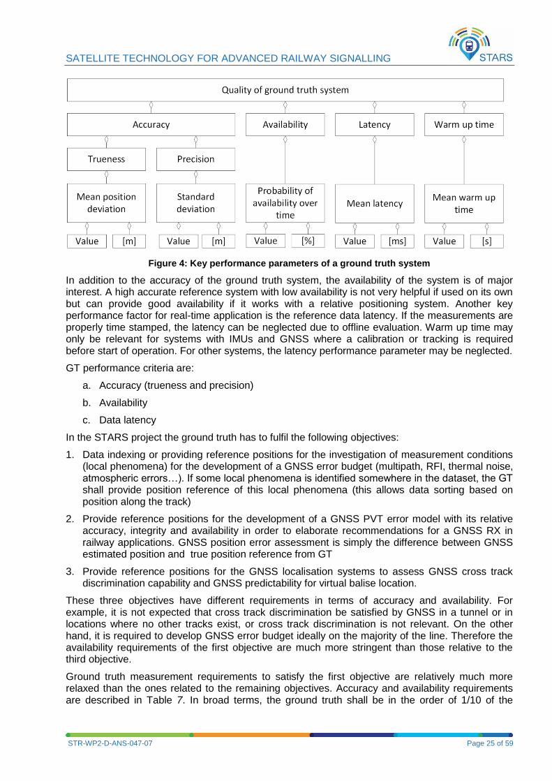
The key performance parameters of a ground truth system are depicted in Figure 4:
SATELLITE TECHNOLOGY FOR ADVANCED RAILWAY SIGNALLING
STR-WP2-D-ANS-047-07 Page 25 of 59
Figure 4: Key performance parameters of a ground truth system
In addition to the accuracy of the ground truth system, the availability of the system is of major interest. A high accurate reference system with low availability is not very helpful if used on its own but can provide good availability if it works with a relative positioning system. Another key performance factor for real-time application is the reference data latency. If the measurements are properly time stamped, the latency can be neglected due to offline evaluation. Warm up time may only be relevant for systems with IMUs and GNSS where a calibration or tracking is required before start of operation. For other systems, the latency performance parameter may be neglected.
GT performance criteria are:
a. Accuracy (trueness and precision)
b. Availability
c. Data latency
In the STARS project the ground truth has to fulfil the following objectives:
1. Data indexing or providing reference positions for the investigation of measurement conditions (local phenomena) for the development of a GNSS error budget (multipath, RFI, thermal noise, atmospheric errors…). If some local phenomena is identified somewhere in the dataset, the GT shall provide position reference of this local phenomena (this allows data sorting based on position along the track)
2. Provide reference positions for the development of a GNSS PVT error model with its relative accuracy, integrity and availability in order to elaborate recommendations for a GNSS RX in railway applications. GNSS position error assessment is simply the difference between GNSS estimated position and true position reference from GT
3. Provide reference positions for the GNSS localisation systems to assess GNSS cross track discrimination capability and GNSS predictability for virtual balise location.
These three objectives have different requirements in terms of accuracy and availability. For example, it is not expected that cross track discrimination be satisfied by GNSS in a tunnel or in locations where no other tracks exist, or cross track discrimination is not relevant. On the other hand, it is required to develop GNSS error budget ideally on the majority of the line. Therefore the availability requirements of the first objective are much more stringent than those relative to the third objective.
Ground truth measurement requirements to satisfy the first objective are relatively much more relaxed than the ones related to the remaining objectives. Accuracy and availability requirements are described in Table 7. In broad terms, the ground truth shall be in the order of 1/10 of the
SATELLITE TECHNOLOGY FOR ADVANCED RAILWAY SIGNALLING
STR-WP2-D-ANS-047-07 Page 26 of 59
estimated accuracy of the system under test. However, given that different objectives are covered by GT, these requirements are relaxed accordingly.
For example, as the capability to discriminate the track based on GNSS has to be verified in STARS, the GT measurement system must allow the measurement of values with an error suitable for such track discrimination. Therefore, the GT measurement system would have accuracy in the transversal direction better than approximately 1.5 m / 10 = 15 cm.
However, this means that at least one GT method should guarantee such accuracy. This method might be based on odometry, the use of physical linked balises, the track survey to georeference the physical balise, or the combination of these techniques.
On the other hand, assessing GNSS SIS error budget does not need such accuracy as the objective is to assess local phenomena by indexing the GNSS measurements in space. Finally, the GT second objective is to assess GNSS/SBAS position error in order to assess integrity. In this case, accurate GT position reference would allow assessing GNSS position error and computing integrity in a reliable way without having to include a margin of error.
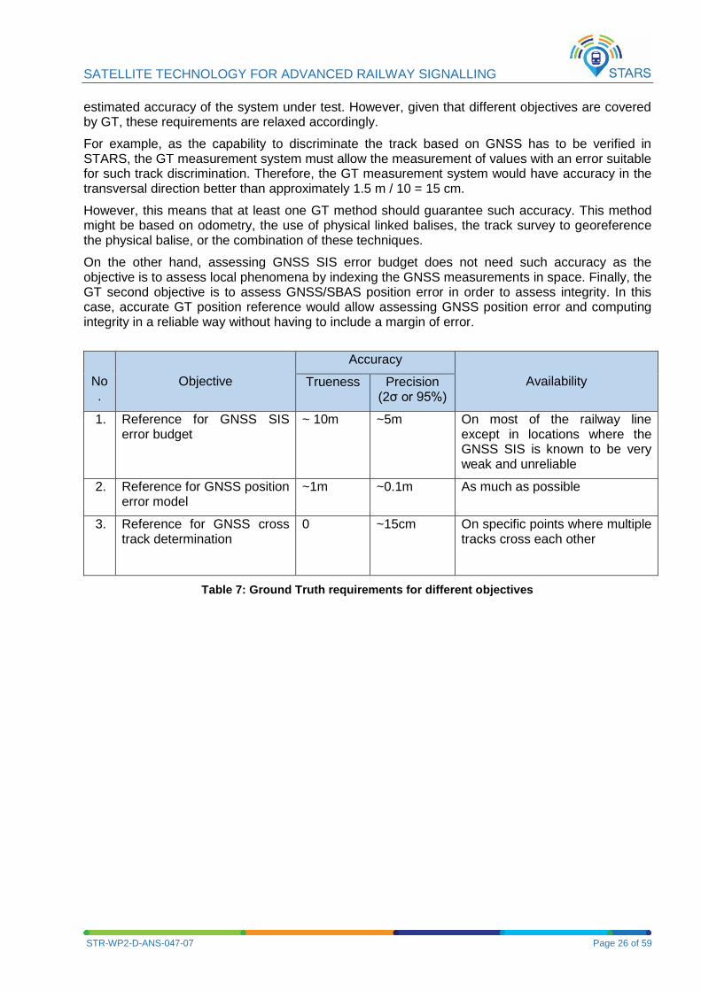
No.
Objective
Accuracy
Availability Trueness Precision (2σ or 95%)
1. Reference for GNSS SIS error budget
~ 10m ~5m On most of the railway line except in locations where the GNSS SIS is known to be very weak and unreliable
2. Reference for GNSS position error model
~1m ~0.1m As much as possible
3. Reference for GNSS cross track determination
0 ~15cm On specific points where multiple tracks cross each other
Table 7: Ground Truth requirements for different objectives
SATELLITE TECHNOLOGY FOR ADVANCED RAILWAY SIGNALLING
STR-WP2-D-ANS-047-07 Page 27 of 59
Absolute reference point (ARP)
N
N
+
1
Wheel tachometer
Absolute reference point reader
Optical correlation sensor
GNSS antenna
Mobile equipmentStationaire equipment
Geo referenced track data
*FIX
CERT
Relative distance
Re
lative
dis
tan
ce
err
or
Absolute
distance
Ab
so
lute
dis
tan
ce
err
or
Reset of distance at
absolute reference
points
Accuracy of absolute
reference point and
detection
Inertial measurement unit
Optical correlation sensor
Inertial measurement unit
Wheel tachometer
(at non free running axel)
D (ARP(N), t)
e (A
RP
(N),
t)
N
Absolute
distance
Ab
so
lute
dis
tan
ce
err
or
Accuracy of absolute
reference point and
detection
D (ARP(N), t)
e (A
RP
(N),
t)
Additional relative
distance errors
By post processing the max.
distance error occurs in the middel
between two absolute reference
points
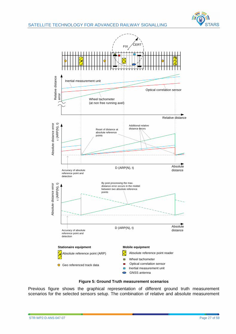
Figure 5: Ground Truth measurement scenarios
Previous figure shows the graphical representation of different ground truth measurement scenarios for the selected sensors setup. The combination of relative and absolute measurement
SATELLITE TECHNOLOGY FOR ADVANCED RAILWAY SIGNALLING
STR-WP2-D-ANS-047-07 Page 28 of 59
sensors will determine the distance errors obtained. It is possible to improve this performance in post-processing.
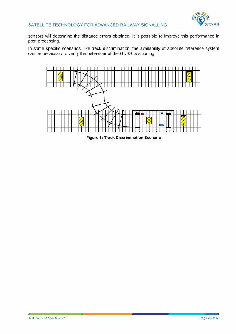
In some specific scenarios, like track discrimination, the availability of absolute reference system can be necessary to verify the behaviour of the GNSS positioning.
N
N
+
1
M
M
+
1
Figure 6: Track Discrimination Scenario
SATELLITE TECHNOLOGY FOR ADVANCED RAILWAY SIGNALLING
STR-WP2-D-ANS-047-07 Page 29 of 59
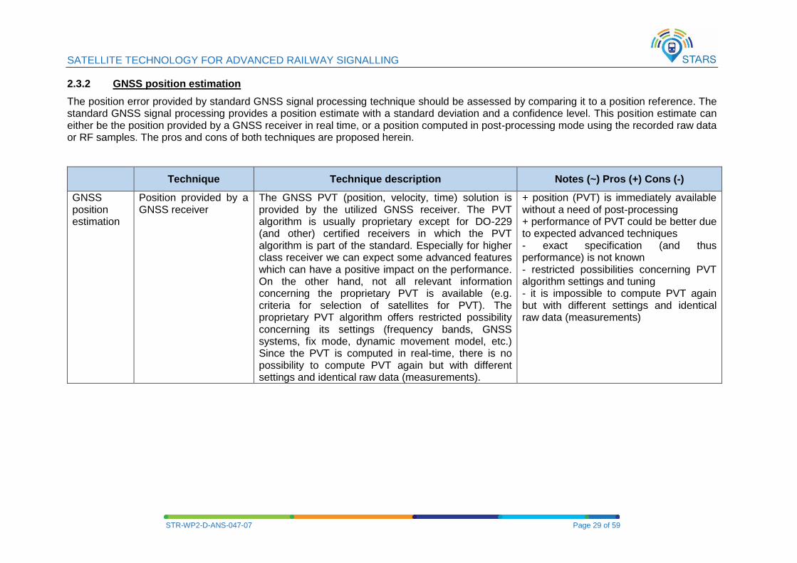
2.3.2 GNSS position estimation
The position error provided by standard GNSS signal processing technique should be assessed by comparing it to a position reference. The standard GNSS signal processing provides a position estimate with a standard deviation and a confidence level. This position estimate can either be the position provided by a GNSS receiver in real time, or a position computed in post-processing mode using the recorded raw data or RF samples. The pros and cons of both techniques are proposed herein.
Technique Technique description Notes (~) Pros (+) Cons (-)
GNSS position estimation
Position provided by a GNSS receiver
The GNSS PVT (position, velocity, time) solution is provided by the utilized GNSS receiver. The PVT algorithm is usually proprietary except for DO-229 (and other) certified receivers in which the PVT algorithm is part of the standard. Especially for higher class receiver we can expect some advanced features which can have a positive impact on the performance. On the other hand, not all relevant information concerning the proprietary PVT is available (e.g. criteria for selection of satellites for PVT). The proprietary PVT algorithm offers restricted possibility concerning its settings (frequency bands, GNSS systems, fix mode, dynamic movement model, etc.) Since the PVT is computed in real-time, there is no possibility to compute PVT again but with different settings and identical raw data (measurements).
+ position (PVT) is immediately available without a need of post-processing + performance of PVT could be better due to expected advanced techniques - exact specification (and thus performance) is not known - restricted possibilities concerning PVT algorithm settings and tuning - it is impossible to compute PVT again but with different settings and identical raw data (measurements)
SATELLITE TECHNOLOGY FOR ADVANCED RAILWAY SIGNALLING
STR-WP2-D-ANS-047-07 Page 30 of 59
Technique Technique description Notes (~) Pros (+) Cons (-)
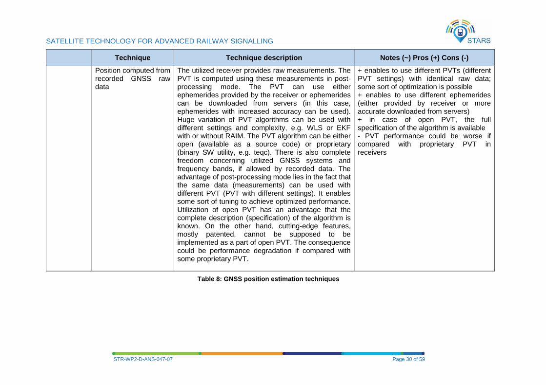
Position computed from recorded GNSS raw data
The utilized receiver provides raw measurements. The PVT is computed using these measurements in post-processing mode. The PVT can use either ephemerides provided by the receiver or ephemerides can be downloaded from servers (in this case, ephemerides with increased accuracy can be used). Huge variation of PVT algorithms can be used with different settings and complexity, e.g. WLS or EKF with or without RAIM. The PVT algorithm can be either open (available as a source code) or proprietary (binary SW utility, e.g. teqc). There is also complete freedom concerning utilized GNSS systems and frequency bands, if allowed by recorded data. The advantage of post-processing mode lies in the fact that the same data (measurements) can be used with different PVT (PVT with different settings). It enables some sort of tuning to achieve optimized performance. Utilization of open PVT has an advantage that the complete description (specification) of the algorithm is known. On the other hand, cutting-edge features, mostly patented, cannot be supposed to be implemented as a part of open PVT. The consequence could be performance degradation if compared with some proprietary PVT.
+ enables to use different PVTs (different PVT settings) with identical raw data; some sort of optimization is possible + enables to use different ephemerides (either provided by receiver or more accurate downloaded from servers) + in case of open PVT, the full specification of the algorithm is available - PVT performance could be worse if compared with proprietary PVT in receivers
Table 8: GNSS position estimation techniques
SATELLITE TECHNOLOGY FOR ADVANCED RAILWAY SIGNALLING
STR-WP2-D-ANS-047-07 Page 31 of 59
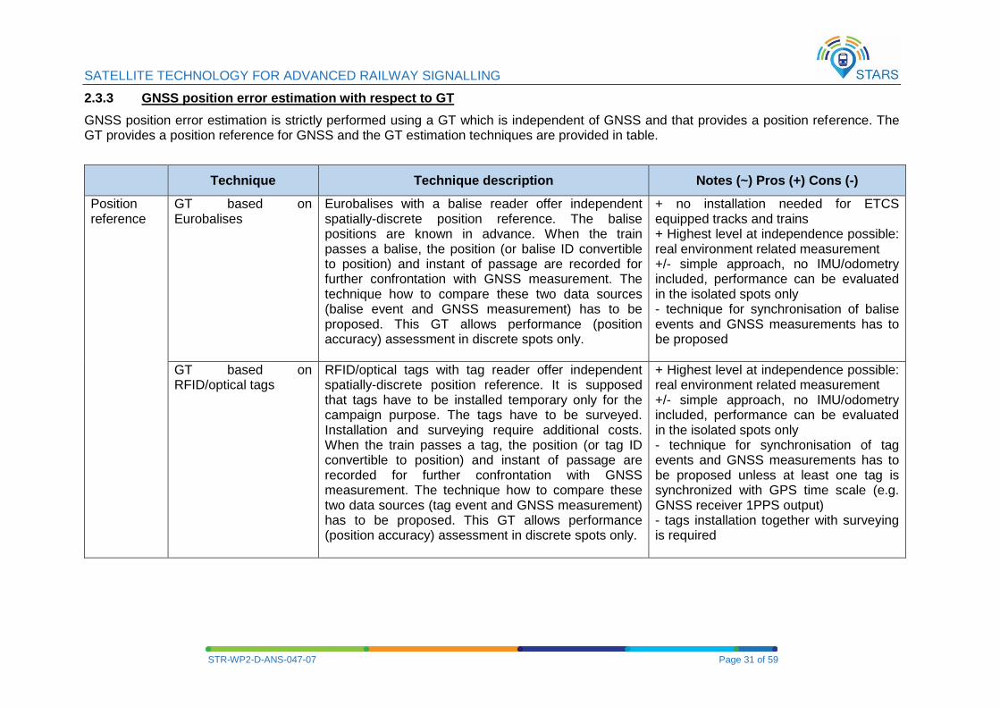
2.3.3 GNSS position error estimation with respect to GT
GNSS position error estimation is strictly performed using a GT which is independent of GNSS and that provides a position reference. The GT provides a position reference for GNSS and the GT estimation techniques are provided in table.
Technique Technique description Notes (~) Pros (+) Cons (-)
Position reference
GT based on Eurobalises
Eurobalises with a balise reader offer independent spatially-discrete position reference. The balise positions are known in advance. When the train passes a balise, the position (or balise ID convertible to position) and instant of passage are recorded for further confrontation with GNSS measurement. The technique how to compare these two data sources (balise event and GNSS measurement) has to be proposed. This GT allows performance (position accuracy) assessment in discrete spots only.
+ no installation needed for ETCS equipped tracks and trains + Highest level at independence possible: real environment related measurement +/- simple approach, no IMU/odometry included, performance can be evaluated in the isolated spots only - technique for synchronisation of balise events and GNSS measurements has to be proposed
GT based on RFID/optical tags
RFID/optical tags with tag reader offer independent spatially-discrete position reference. It is supposed that tags have to be installed temporary only for the campaign purpose. The tags have to be surveyed. Installation and surveying require additional costs. When the train passes a tag, the position (or tag ID convertible to position) and instant of passage are recorded for further confrontation with GNSS measurement. The technique how to compare these two data sources (tag event and GNSS measurement) has to be proposed. This GT allows performance (position accuracy) assessment in discrete spots only.
+ Highest level at independence possible: real environment related measurement +/- simple approach, no IMU/odometry included, performance can be evaluated in the isolated spots only - technique for synchronisation of tag events and GNSS measurements has to be proposed unless at least one tag is synchronized with GPS time scale (e.g. GNSS receiver 1PPS output) - tags installation together with surveying is required
SATELLITE TECHNOLOGY FOR ADVANCED RAILWAY SIGNALLING
STR-WP2-D-ANS-047-07 Page 32 of 59
Technique Technique description Notes (~) Pros (+) Cons (-)
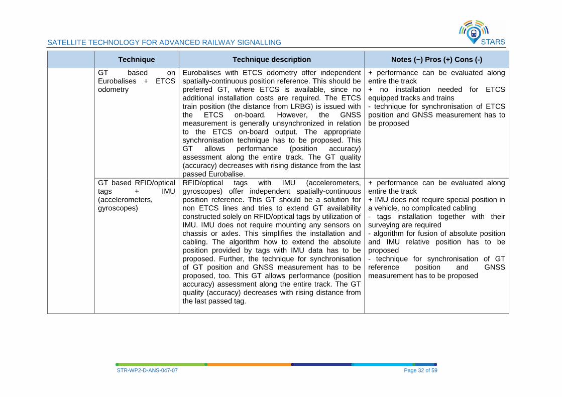
GT based on Eurobalises + ETCS odometry
Eurobalises with ETCS odometry offer independent spatially-continuous position reference. This should be preferred GT, where ETCS is available, since no additional installation costs are required. The ETCS train position (the distance from LRBG) is issued with the ETCS on-board. However, the GNSS measurement is generally unsynchronized in relation to the ETCS on-board output. The appropriate synchronisation technique has to be proposed. This GT allows performance (position accuracy) assessment along the entire track. The GT quality (accuracy) decreases with rising distance from the last passed Eurobalise.
+ performance can be evaluated along entire the track + no installation needed for ETCS equipped tracks and trains - technique for synchronisation of ETCS position and GNSS measurement has to be proposed
GT based RFID/optical tags + IMU (accelerometers, gyroscopes)
RFID/optical tags with IMU (accelerometers, gyroscopes) offer independent spatially-continuous position reference. This GT should be a solution for non ETCS lines and tries to extend GT availability constructed solely on RFID/optical tags by utilization of IMU. IMU does not require mounting any sensors on chassis or axles. This simplifies the installation and cabling. The algorithm how to extend the absolute position provided by tags with IMU data has to be proposed. Further, the technique for synchronisation of GT position and GNSS measurement has to be proposed, too. This GT allows performance (position accuracy) assessment along the entire track. The GT quality (accuracy) decreases with rising distance from the last passed tag.
+ performance can be evaluated along entire the track + IMU does not require special position in a vehicle, no complicated cabling - tags installation together with their surveying are required - algorithm for fusion of absolute position and IMU relative position has to be proposed - technique for synchronisation of GT reference position and GNSS measurement has to be proposed
SATELLITE TECHNOLOGY FOR ADVANCED RAILWAY SIGNALLING
STR-WP2-D-ANS-047-07 Page 33 of 59
Technique Technique description Notes (~) Pros (+) Cons (-)
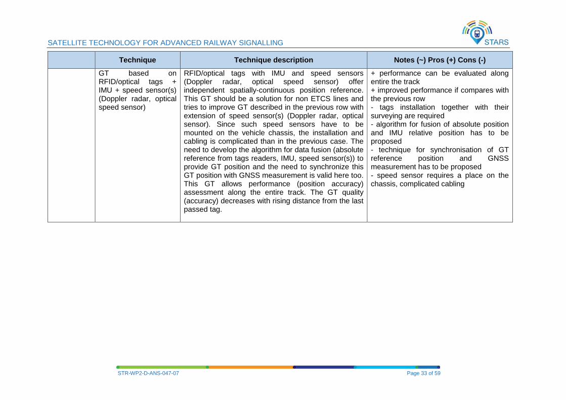
GT based on RFID/optical tags + IMU + speed sensor(s) (Doppler radar, optical speed sensor)
RFID/optical tags with IMU and speed sensors (Doppler radar, optical speed sensor) offer independent spatially-continuous position reference. This GT should be a solution for non ETCS lines and tries to improve GT described in the previous row with extension of speed sensor(s) (Doppler radar, optical sensor). Since such speed sensors have to be mounted on the vehicle chassis, the installation and cabling is complicated than in the previous case. The need to develop the algorithm for data fusion (absolute reference from tags readers, IMU, speed sensor(s)) to provide GT position and the need to synchronize this GT position with GNSS measurement is valid here too. This GT allows performance (position accuracy) assessment along the entire track. The GT quality (accuracy) decreases with rising distance from the last passed tag.
+ performance can be evaluated along entire the track + improved performance if compares with the previous row - tags installation together with their surveying are required - algorithm for fusion of absolute position and IMU relative position has to be proposed - technique for synchronisation of GT reference position and GNSS measurement has to be proposed - speed sensor requires a place on the chassis, complicated cabling
SATELLITE TECHNOLOGY FOR ADVANCED RAILWAY SIGNALLING
STR-WP2-D-ANS-047-07 Page 34 of 59
Technique Technique description Notes (~) Pros (+) Cons (-)
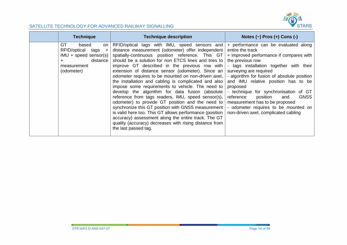
GT based on RFID/optical tags + IMU + speed sensor(s) + distance measurement (odometer)
RFID/optical tags with IMU, speed sensors and distance measurement (odometer) offer independent spatially-continuous position reference. This GT should be a solution for non ETCS lines and tries to improve GT described in the previous row with extension of distance sensor (odometer). Since an odometer requires to be mounted on non-driven axel, the installation and cabling is complicated and also impose some requirements to vehicle. The need to develop the algorithm for data fusion (absolute reference from tags readers, IMU, speed sensor(s), odometer) to provide GT position and the need to synchronize this GT position with GNSS measurement is valid here too. This GT allows performance (position accuracy) assessment along the entire track. The GT quality (accuracy) decreases with rising distance from the last passed tag.
+ performance can be evaluated along entire the track + improved performance if compares with the previous row - tags installation together with their surveying are required - algorithm for fusion of absolute position and IMU relative position has to be proposed - technique for synchronisation of GT reference position and GNSS measurement has to be proposed - odometer requires to be mounted on non-driven axel, complicated cabling
SATELLITE TECHNOLOGY FOR ADVANCED RAILWAY SIGNALLING
STR-WP2-D-ANS-047-07 Page 35 of 59
Technique Technique description Notes (~) Pros (+) Cons (-)
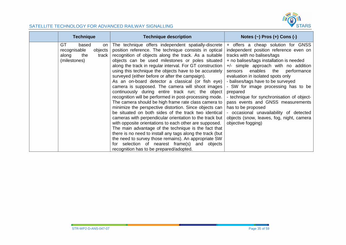
GT based on recognisable objects along the track (milestones)
The technique offers independent spatially-discrete position reference. The technique consists in optical recognition of objects along the track. As a suitable objects can be used milestones or poles situated along the track in regular interval. For GT construction using this technique the objects have to be accurately surveyed (either before or after the campaign). As an on-board detector a classical (or fish eye) camera is supposed. The camera will shoot images continuously during entire track run; the object recognition will be performed in post-processing mode. The camera should be high frame rate class camera to minimize the perspective distortion. Since objects can be situated on both sides of the track two identical cameras with perpendicular orientation to the track but with opposite orientations to each other are supposed. The main advantage of the technique is the fact that there is no need to install any tags along the track (but the need to survey those remains). An appropriate SW for selection of nearest frame(s) and objects recognition has to be prepared/adopted.
+ offers a cheap solution for GNSS independent position reference even on tracks with no balises/tags + no balises/tags installation is needed +/- simple approach with no addition sensors enables the performance evaluation in isolated spots only - balises/tags have to be surveyed - SW for image processing has to be prepared - technique for synchronisation of object-pass events and GNSS measurements has to be proposed - occasional unavailability of detected objects (snow, leaves, fog, night, camera objective fogging)
SATELLITE TECHNOLOGY FOR ADVANCED RAILWAY SIGNALLING
STR-WP2-D-ANS-047-07 Page 36 of 59
Technique Technique description Notes (~) Pros (+) Cons (-)
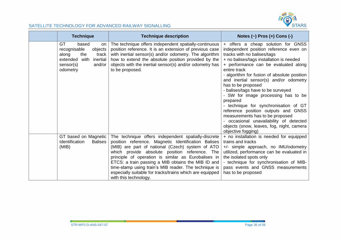
GT based on recognisable objects along the track extended with inertial sensor(s) and/or odometry
The technique offers independent spatially-continuous position reference. It is an extension of previous case with inertial sensor(s) and/or odometry. The algorithm how to extend the absolute position provided by the objects with the inertial sensor(s) and/or odometry has to be proposed.
+ offers a cheap solution for GNSS independent position reference even on tracks with no balises/tags + no balises/tags installation is needed + performance can be evaluated along entire track - algorithm for fusion of absolute position and inertial sensor(s) and/or odometry has to be proposed - balises/tags have to be surveyed - SW for image processing has to be prepared - technique for synchronisation of GT reference position outputs and GNSS measurements has to be proposed - occasional unavailability of detected objects (snow, leaves, fog, night, camera objective fogging)
GT based on Magnetic Identification Balises (MIB)
The technique offers independent spatially-discrete position reference. Magnetic Identification Balises (MIB) are part of national (Czech) system of ATO which provide absolute position reference. The principle of operation is similar as Eurobalises in ETCS: a train passing a MIB obtains the MIB ID and time-stamp using train’s MIB reader. The technique is especially suitable for tracks/trains which are equipped with this technology.
+ no installation is needed for equipped trains and tracks +/- simple approach, no IMU/odometry utilized, performance can be evaluated in the isolated spots only - technique for synchronisation of MIB-pass events and GNSS measurements has to be proposed
SATELLITE TECHNOLOGY FOR ADVANCED RAILWAY SIGNALLING
STR-WP2-D-ANS-047-07 Page 37 of 59
Technique Technique description Notes (~) Pros (+) Cons (-)
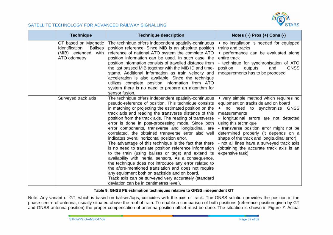
GT based on Magnetic Identification Balises (MIB) extended with ATO odometry
The technique offers independent spatially-continuous position reference. Since MIB is an absolute position reference of national ATO system the complete ATO position information can be used. In such case, the position information consists of travelled distance from the last passed MIB together with the MIB ID and time-stamp. Additional information as train velocity and acceleration is also available. Since the technique utilizes complete position information from ATO system there is no need to prepare an algorithm for sensor fusion.
+ no installation is needed for equipped trains and tracks + performance can be evaluated along entire track - technique for synchronisation of ATO position outputs and GNSS measurements has to be proposed
Surveyed track axis The technique offers independent spatially-continuous pseudo-reference of position. This technique consists in matching or projecting the estimated position on the track axis and reading the transverse distance of this position from the track axis. The reading of transverse error is done in post-processing mode. Since both error components, transverse and longitudinal, are correlated, the obtained transverse error also well indicates overall horizontal position error. The advantage of this technique is the fact that there is no need to translate position reference information to the train (using balises or tags) and extend its availability with inertial sensors. As a consequence, the technique does not introduce any error related to the afore-mentioned translation and does not require any equipment both on trackside and on board. Track axis can be surveyed very accurately (standard deviation can be in centimetres level).
+ very simple method which requires no equipment on trackside and on board + no need to synchronize GNSS measurements - longitudinal errors are not detected using this technique - transverse position error might not be determined properly (it depends on a shape of the track and longitudinal error) - not all lines have a surveyed track axis (obtaining the accurate track axis is an expensive task)
Table 9: GNSS PE estimation techniques relative to GNSS independent GT
Note: Any variant of GT, which is based on balises/tags, coincides with the axis of track. The GNSS solution provides the position in the phase centre of antenna, usually situated above the roof of train. To enable a comparison of both positions (reference position given by GT and GNSS antenna position) the proper compensation of antenna position offset must be done. The situation is shown in Figure 7. Actual

SATELLITE TECHNOLOGY FOR ADVANCED RAILWAY SIGNALLING
STR-WP2-D-ANS-047-07 Page 38 of 59
train tilt, track super elevation and antenna position height above a track have to be considered for the compensation. Position reference based on RTK (PPK) gives the reference positions in the common point with GNSS measurement, which is the phase centre of antenna. No compensation is needed in this case.
GNSS
antenna
GT
Calculated
GNSS based
Navigation
Solution
Figure 7: Relationship between real train position, estimated GT, GNSS antenna location, and computed GNSS position (PVT)
2.3.4 GNSS position error assessment with GNSS dependent position reference
The standard GNSS position (PVT) error can be examined through comparison with GNSS differential techniques (e.g. RTK) and position error performance can be derived. It should be mentioned that RTK network stations are supposed to be in a similar environment to that of the OBU GNSS receiver, so that they are affected by the same error sources. This is not fully compatible with the idea of rail hostile scenarios. In fact, any local phenomena will still be present at the user side. The aforementioned techniques are described in the following.
SATELLITE TECHNOLOGY FOR ADVANCED RAILWAY SIGNALLING
STR-WP2-D-ANS-047-07 Page 39 of 59
Technique Technique description Notes (~) Pros (+) Cons (-)
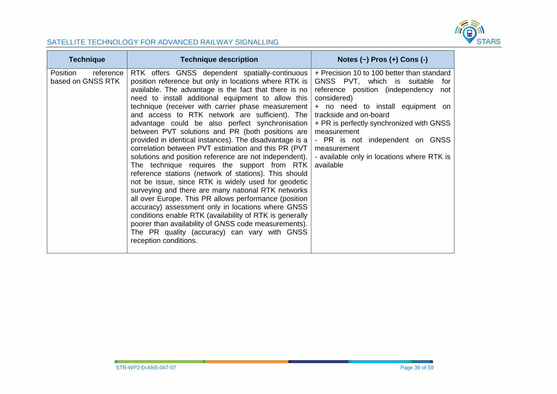
Position reference based on GNSS RTK
RTK offers GNSS dependent spatially-continuous position reference but only in locations where RTK is available. The advantage is the fact that there is no need to install additional equipment to allow this technique (receiver with carrier phase measurement and access to RTK network are sufficient). The advantage could be also perfect synchronisation between PVT solutions and PR (both positions are provided in identical instances). The disadvantage is a correlation between PVT estimation and this PR (PVT solutions and position reference are not independent). The technique requires the support from RTK reference stations (network of stations). This should not be issue, since RTK is widely used for geodetic surveying and there are many national RTK networks all over Europe. This PR allows performance (position accuracy) assessment only in locations where GNSS conditions enable RTK (availability of RTK is generally poorer than availability of GNSS code measurements). The PR quality (accuracy) can vary with GNSS reception conditions.
+ Precision 10 to 100 better than standard GNSS PVT, which is suitable for reference position (independency not considered) + no need to install equipment on trackside and on-board + PR is perfectly synchronized with GNSS measurement - PR is not independent on GNSS measurement - available only in locations where RTK is available
SATELLITE TECHNOLOGY FOR ADVANCED RAILWAY SIGNALLING
STR-WP2-D-ANS-047-07 Page 40 of 59
Technique Technique description Notes (~) Pros (+) Cons (-)
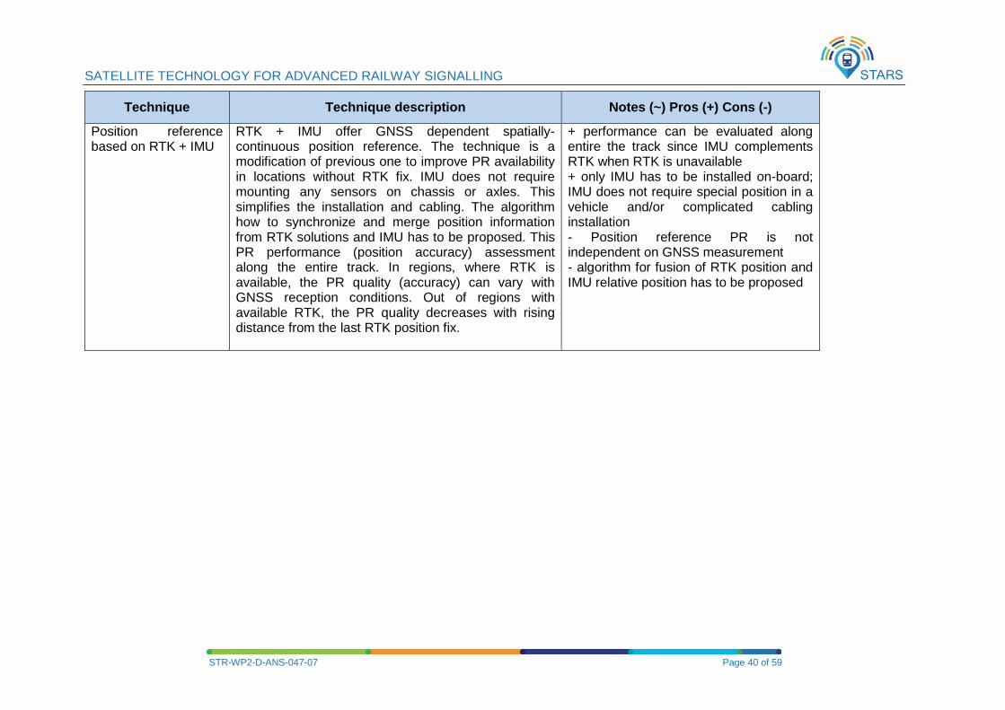
Position reference based on RTK + IMU
RTK + IMU offer GNSS dependent spatially-continuous position reference. The technique is a modification of previous one to improve PR availability in locations without RTK fix. IMU does not require mounting any sensors on chassis or axles. This simplifies the installation and cabling. The algorithm how to synchronize and merge position information from RTK solutions and IMU has to be proposed. This PR performance (position accuracy) assessment along the entire track. In regions, where RTK is available, the PR quality (accuracy) can vary with GNSS reception conditions. Out of regions with available RTK, the PR quality decreases with rising distance from the last RTK position fix.
+ performance can be evaluated along entire the track since IMU complements RTK when RTK is unavailable + only IMU has to be installed on-board; IMU does not require special position in a vehicle and/or complicated cabling installation - Position reference PR is not independent on GNSS measurement - algorithm for fusion of RTK position and IMU relative position has to be proposed
SATELLITE TECHNOLOGY FOR ADVANCED RAILWAY SIGNALLING
STR-WP2-D-ANS-047-07 Page 41 of 59
Technique Technique description Notes (~) Pros (+) Cons (-)
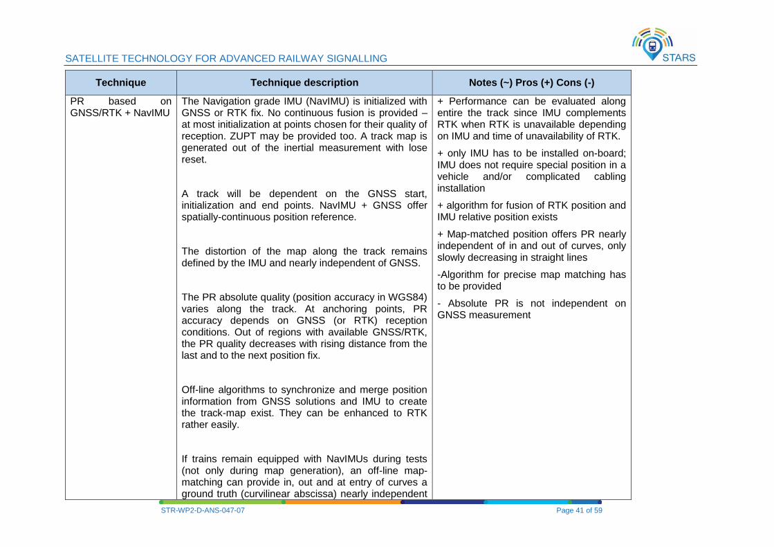
PR based on GNSS/RTK + NavIMU
The Navigation grade IMU (NavIMU) is initialized with GNSS or RTK fix. No continuous fusion is provided – at most initialization at points chosen for their quality of reception. ZUPT may be provided too. A track map is generated out of the inertial measurement with lose reset.
A track will be dependent on the GNSS start, initialization and end points. NavIMU + GNSS offer spatially-continuous position reference.
The distortion of the map along the track remains defined by the IMU and nearly independent of GNSS.
The PR absolute quality (position accuracy in WGS84) varies along the track. At anchoring points, PR accuracy depends on GNSS (or RTK) reception conditions. Out of regions with available GNSS/RTK, the PR quality decreases with rising distance from the last and to the next position fix.
Off-line algorithms to synchronize and merge position information from GNSS solutions and IMU to create the track-map exist. They can be enhanced to RTK rather easily.
If trains remain equipped with NavIMUs during tests (not only during map generation), an off-line map-matching can provide in, out and at entry of curves a ground truth (curvilinear abscissa) nearly independent
+ Performance can be evaluated along entire the track since IMU complements RTK when RTK is unavailable depending on IMU and time of unavailability of RTK.
+ only IMU has to be installed on-board; IMU does not require special position in a vehicle and/or complicated cabling installation
+ algorithm for fusion of RTK position and IMU relative position exists
+ Map-matched position offers PR nearly independent of in and out of curves, only slowly decreasing in straight lines
-Algorithm for precise map matching has to be provided
- Absolute PR is not independent on GNSS measurement
SATELLITE TECHNOLOGY FOR ADVANCED RAILWAY SIGNALLING
STR-WP2-D-ANS-047-07 Page 42 of 59
Technique Technique description Notes (~) Pros (+) Cons (-)
of GNSS, only slowly decreasing in quality in straight lines while the vehicle distance to the closest curve increases.
NAvIMU does not require mounting any sensors on chassis or axles. This simplifies the installation and cabling.
PR based on a stabilized GNSS receiver located nearby the measurement point
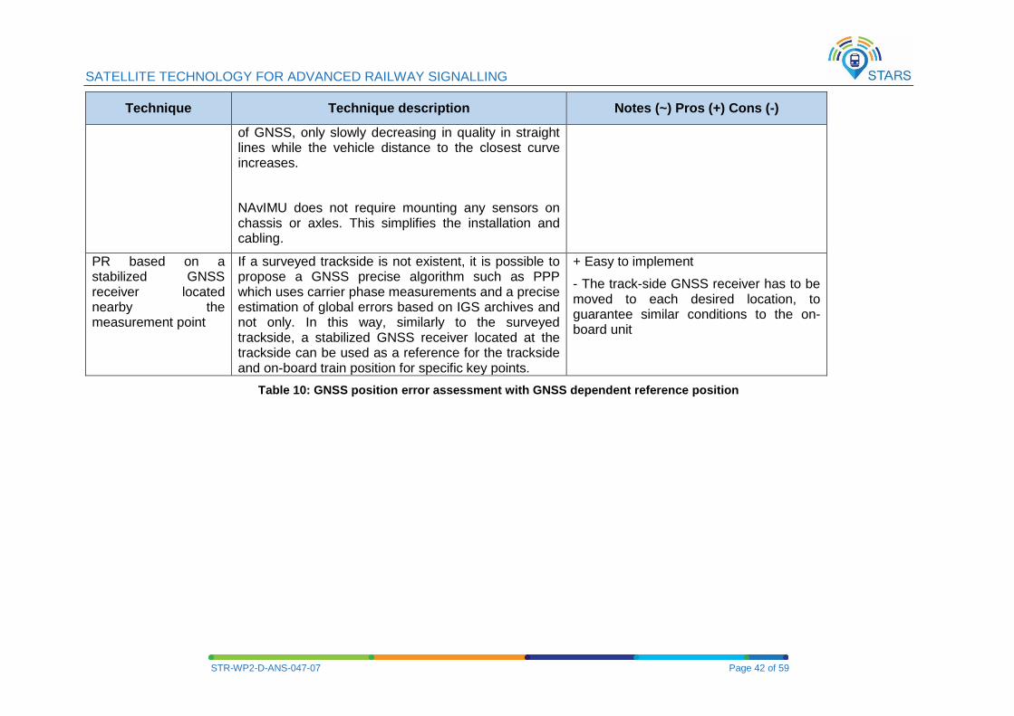
If a surveyed trackside is not existent, it is possible to propose a GNSS precise algorithm such as PPP which uses carrier phase measurements and a precise estimation of global errors based on IGS archives and not only. In this way, similarly to the surveyed trackside, a stabilized GNSS receiver located at the trackside can be used as a reference for the trackside and on-board train position for specific key points.
+ Easy to implement
- The track-side GNSS receiver has to be moved to each desired location, to guarantee similar conditions to the on-board unit
Table 10: GNSS position error assessment with GNSS dependent reference position
SATELLITE TECHNOLOGY FOR ADVANCED RAILWAY SIGNALLING
STR-WP2-D-ANS-047-07 Page 43 of 59
2.3.5 GNSS position error assessment based on particular GNSS signal quality and satellite geometry
The GNSS position (PVT) error assessment can be also based on different approach than the comparison of the reference position or the GT and the measured GNSS position. In its simplest form the approach can be described as follows. If the standard deviation for pseudo range measurement σURE is estimated and satellite geometry is known as GDOP (Geometric Dilution of Precision), then the standard deviations of position in all tree axes and standard deviation of time bias can be written:
√(σx2 + σy
2 + σz2 + σb
2) = GDOP σURE
- where σURE can be estimated from the signal quality indicator (C/N0, SNR), GDOP can be computed from GNSS receiver and GNSS satellites position.
Note that this is applicable only when GNSS signal reception is in LOS conditions. In case of NLOS signal reception conditions, the GDOP (computed with vectors pointing from user location to GNSS satellites) does not represent anymore the quality of the measure. Moreover, this approach relies on the assumption that pseudo range errors have a Gaussian distribution, which is not true in NLOS conditions.
2.4 PERFORMANCE AND SPECIFICATIONS OF INDIVIDUAL LINE EQUIPMENT MAINLY FOR GT
ASSESSMENT
In this section, the different absolute/relative positioning systems and possible combinations for the provision of GT are proposed for each railway line. Detailed information on the GT performance of such sensors (when possible) is given in terms of accuracy with confidence level and availability.
2.4.1 Eurobalise /Balise Transmission Module
A Eurobalise is a wayside Transmission Unit that uses the Magnetic Transponder Technology. Its main function is to transmit and/or receive signals through the air gap. The Balise is a single device mounted on the track, which communicates with a train passing over it. A Eurobalise fulfils the mandatory requirements of clauses 4 and 5 of the FFFIS for Eurobalise (UNISIG subset 036 [6]),
It is expected that Eurobalises are already installed on the railway tracks and purchase and installation of this equipment is out of the scope of the project. A Eurobalise complies with the standards defined in subset 036 [6] and is characterized (in case of vital purposes, meaning SIL4) by a location accuracy of +/-1m (clause 4.2.10.2 of subset 036 [6]). From the rules of the normally distributed data, SIL4 specification is equivalent to a confidence level of the order of 6-sigma to 7-sigma. Alternatively, a Eurobalise is characterized by a location accuracy of +/-16.66 cm with one-sigma confidence level. This is of the order of the highest required GT performance in Table 7 of § 2.3.1.
2.4.2 Magnetic Identification Balise (MIB)
A Magnetic Identification Balise (MIB) is wayside passive marker. Its principle and function is similar to Eurobalise. It is an important part of the national CRV&AVV (Central Register Regulator & Automatic Vehicle Guidance) systems for Automatic Train Operation (ATO), which is designed for railway network and metro application and which provides the absolute reference position for the on-board unit of ATO system.
MIB (MIB6) consists of a set of 8 permanent magnets which are arranged in the beam located on a track between the rails. Orientation of the magnets (i.e. their polarity) in the beam enables to achieve coding with Hamming distance H=8 and more than 30 000 different combinations.
MIBs are located with density approximately 2-3 MIBs per kilometre.
SATELLITE TECHNOLOGY FOR ADVANCED RAILWAY SIGNALLING
STR-WP2-D-ANS-047-07 Page 44 of 59
It is expected that Magnetic Identification Balises are already installed on selected railway track and purchase and installation of this equipment is out of the scope of the project. A Magnetic Identification Balise is characterized by location accuracy of +/-3cm (1sigma), both ends of a beam are surveyed. This is of the order of the highest required GT performance in Table 7 of § 2.3.1.
2.4.3 Wheel Tachometer
The wheel tachometer measures the rotation speed of a wheel. It is expressed in terms of revolutions per time interval. Based on the revolutions per time interval the travelled distance can be calculated. Due to the slip between the wheel and the tracks the distance error accumulates over time and distance. Thereby, the error is strongly dependent on the friction between the wheel and the rails, which in turn is strongly depending on environmental conditions. Hence, the error varies and it is very challenging to predict. The wheel tachometer can be mounted on a powered or free spinning. The free spinning wheel enables a higher accuracy due to reduced slip.
But due to lower accuracy of the wheel tachometer compared to the optical encoder it is questionable whether the minimal accuracy gain from this equipment justifies the expenditure. However, the wheel tachometer could perfectly serve as a backup sensor for the case of an optical encoder failure.
It is critical in which axel it is installed. This relative sensor can have problems of slip and slide of the wheel losing the precision considerably. It is recommended to have a protocol to measure the wheel diameter for the measurement campaign.
General info about confidence level that is expected to be reached by such sensors after synchronisation with GNSS data using GNSS receiver PPS.
2.4.4 RFID
A RFID tag is a passive wayside absolute position marker which will be installed in the centre of sleeper. The reason why this type of markers is included into the project is the fact that the regional line Číčenice-Volary (which has been selected for the measurement in the Czech Republic) has no suitable markers installed for GT construction. RFIDs will be installed just for this project purpose and corresponding on-board device (RFID reader) will be part of AZD’s measurement system only.
The Harting RFID technology has been selected. Particularly, the RF-R300 unit will be used as a RFID reader.
RFID tags will be installed in regular distance (500 meters) in entire line length of 56 km. Further, parallel tracks in stations will be deployed with additional RFIDs near the switches on both sides. Thus the parallel tracks can be easily distinguished.
It is not easy now to estimate complete positioning performance of this technology, since practical feeling is missing now. The RFID positions have been surveyed with 3cm accuracy (1σ). The complete positioning performance will be derived in post processing by the confrontation of RFID positions with PPK positioning technique. To minimise GNSS environment impact on the performance assessment the data from open sky environment will be used only.
2.4.5 Optical Encoder
Optical encoders measure speed, distance and sometimes acceleration by using an optical sensor and correlation algorithms. Similarly to the wheel tachometer, the error on distance measurements accumulates with the travel distance. A list of optical encoders that are available for railway applications is shown in Table 11. The non-contact Hasler CoRRail sensor offers a direct measurement of a rail vehicle velocity and direction of movement, using the railhead surface as a reference. The CoRRail provides high accuracy speed and distance measurement.
Some specific characteristics for the Hasler CoRRail 1000 sensor are included:
- Reference surface: Railhead
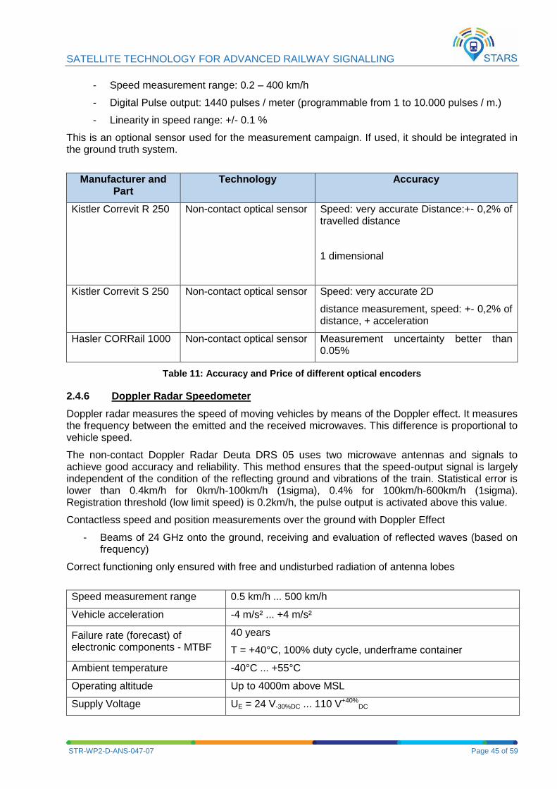
SATELLITE TECHNOLOGY FOR ADVANCED RAILWAY SIGNALLING
STR-WP2-D-ANS-047-07 Page 45 of 59
- Speed measurement range: 0.2 – 400 km/h
- Digital Pulse output: 1440 pulses / meter (programmable from 1 to 10.000 pulses / m.)
- Linearity in speed range: +/- 0.1 %
This is an optional sensor used for the measurement campaign. If used, it should be integrated in the ground truth system.
Manufacturer and Part
Technology Accuracy
Kistler Correvit R 250 Non-contact optical sensor Speed: very accurate Distance:+- 0,2% of travelled distance
1 dimensional
Kistler Correvit S 250 Non-contact optical sensor Speed: very accurate 2D
distance measurement, speed: +- 0,2% of distance, + acceleration
Hasler CORRail 1000 Non-contact optical sensor Measurement uncertainty better than 0.05%
Table 11: Accuracy and Price of different optical encoders
2.4.6 Doppler Radar Speedometer
Doppler radar measures the speed of moving vehicles by means of the Doppler effect. It measures the frequency between the emitted and the received microwaves. This difference is proportional to vehicle speed.
The non-contact Doppler Radar Deuta DRS 05 uses two microwave antennas and signals to achieve good accuracy and reliability. This method ensures that the speed-output signal is largely independent of the condition of the reflecting ground and vibrations of the train. Statistical error is lower than 0.4km/h for 0km/h-100km/h (1sigma), 0.4% for 100km/h-600km/h (1sigma). Registration threshold (low limit speed) is 0.2km/h, the pulse output is activated above this value.
Contactless speed and position measurements over the ground with Doppler Effect
- Beams of 24 GHz onto the ground, receiving and evaluation of reflected waves (based on frequency)
Correct functioning only ensured with free and undisturbed radiation of antenna lobes
Speed measurement range 0.5 km/h ... 500 km/h
Vehicle acceleration -4 m/s² ... +4 m/s²
Failure rate (forecast) of electronic components - MTBF
40 years
T = +40°C, 100% duty cycle, underframe container
Ambient temperature -40°C ... +55°C
Operating altitude Up to 4000m above MSL
Supply Voltage UE = 24 V-30%DC ... 110 V+40%DC
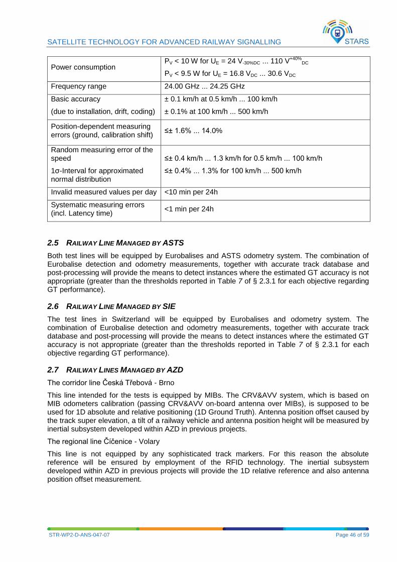
SATELLITE TECHNOLOGY FOR ADVANCED RAILWAY SIGNALLING
STR-WP2-D-ANS-047-07 Page 46 of 59
Power consumption PV < 10 W for UE = 24 V-30%DC ... 110 V+40%
DC
PV < 9.5 W for UE = 16.8 VDC ... 30.6 VDC
Frequency range 24.00 GHz ... 24.25 GHz
Basic accuracy
(due to installation, drift, coding)
± 0.1 km/h at 0.5 km/h ... 100 km/h
± 0.1% at 100 km/h ... 500 km/h
Position-dependent measuring errors (ground, calibration shift)
≤± 1.6% ... 14.0%
Random measuring error of the speed
1σ-Interval for approximated normal distribution
≤± 0.4 km/h ... 1.3 km/h for 0.5 km/h ... 100 km/h
≤± 0.4% ... 1.3% for 100 km/h ... 500 km/h
Invalid measured values per day <10 min per 24h
Systematic measuring errors (incl. Latency time)
<1 min per 24h
2.5 RAILWAY LINE MANAGED BY ASTS
Both test lines will be equipped by Eurobalises and ASTS odometry system. The combination of Eurobalise detection and odometry measurements, together with accurate track database and post-processing will provide the means to detect instances where the estimated GT accuracy is not appropriate (greater than the thresholds reported in Table 7 of § 2.3.1 for each objective regarding GT performance).
2.6 RAILWAY LINE MANAGED BY SIE
The test lines in Switzerland will be equipped by Eurobalises and odometry system. The combination of Eurobalise detection and odometry measurements, together with accurate track database and post-processing will provide the means to detect instances where the estimated GT accuracy is not appropriate (greater than the thresholds reported in Table 7 of § 2.3.1 for each objective regarding GT performance).
2.7 RAILWAY LINES MANAGED BY AZD
The corridor line Česká Třebová - Brno
This line intended for the tests is equipped by MIBs. The CRV&AVV system, which is based on MIB odometers calibration (passing CRV&AVV on-board antenna over MIBs), is supposed to be used for 1D absolute and relative positioning (1D Ground Truth). Antenna position offset caused by the track super elevation, a tilt of a railway vehicle and antenna position height will be measured by inertial subsystem developed within AZD in previous projects.
The regional line Číčenice - Volary
This line is not equipped by any sophisticated track markers. For this reason the absolute reference will be ensured by employment of the RFID technology. The inertial subsystem developed within AZD in previous projects will provide the 1D relative reference and also antenna position offset measurement.
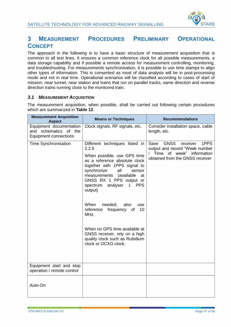
SATELLITE TECHNOLOGY FOR ADVANCED RAILWAY SIGNALLING
STR-WP2-D-ANS-047-07 Page 47 of 59
3 MEASUREMENT PROCEDURES PRELIMINARY OPERATIONAL
CONCEPT The approach in the following is to have a basic structure of measurement acquisition that is common to all test lines. It ensures a common reference clock for all possible measurements, a data storage capability and if possible a remote access for measurement controlling, monitoring, and troubleshooting. For measurements synchronisation, it is possible to use time stamps to align other types of information. This is consented as most of data analysis will be in post-processing mode and not in real time. Operational scenarios will be classified according to cases of start of mission, near tunnel, near station and trains that run on parallel tracks, same direction and reverse direction trains running close to the monitored train.
3.1 MEASUREMENT ACQUISITION
The measurement acquisition, when possible, shall be carried out following certain procedures which are summarized in Table 12.
Measurement Acquisition Aspect
Means or Techniques Recommendations
Equipment documentation and schematics of the Equipment connections
Clock signals, RF signals, etc. Consider installation space, cable length, etc.
Time Synchronisation Different techniques listed in 2.2.6
When possible, use GPS time as a reference absolute clock together with 1PPS signal to synchronize all sensor measurements (available at GNSS RX 1 PPS output or spectrum analyser 1 PPS output)
When needed, also use reference frequency of 10 MHz.
When no GPS time available at GNSS receiver, rely on a high quality clock such as Rubidium clock or OCXO clock.
Save GNSS receiver 1PPS output and record “Week number / Time of week” information obtained from the GNSS receiver
Equipment start and stop operation / remote control
Auto-On

SATELLITE TECHNOLOGY FOR ADVANCED RAILWAY SIGNALLING
STR-WP2-D-ANS-047-07 Page 48 of 59
Measurement Acquisition Aspect
Means or Techniques Recommendations
Auto-Off
Battery back-up
Data recovery and archiving
Hard disks, SSD
Remote troubleshooting and diagnostics
Modular Measurement
Software Core Approach
Test Specific data
Table 12: Measurement Acquisition aspects
3.1.1 Procedures related to Time Synchronisation
Time synchronisation will be ensured by the different techniques listed in 2.2.6
3.1.2 Procedures related to Real Time Processor
There are no requirements for the installation of the real-time system on board. If shocks are expected larger than allowed in the value written in the corresponding manual, shock absorbers have to be used. In highly dynamic test scenarios the usage of shock observers has proved to be helpful even if estimated shocks are less than the maximum allowed.
The real-time processor has to be provided with power. And shall be positioned at a position within the vehicle so that the cable length to the sensors is as short as possible.
3.1.3 Procedures related to data Acquisition Computer
The data acquisition computer shall be mounted close to the real-time processor. It has to be connected to the real-time processor and power.
3.1.4 Data Format
GNSS receivers proprietary file format
GNSS receivers raw data RINEX preferably 3.0
GNSS receivers PVT NMEA
3.1.5 Naming Conventions
The file naming convention is derived from RINEX version 3.02 and later and has been adapted to this project. The name of files should simplify sorting of data coming from various equipment and collected in different test sites.
The file name consists of following fields:
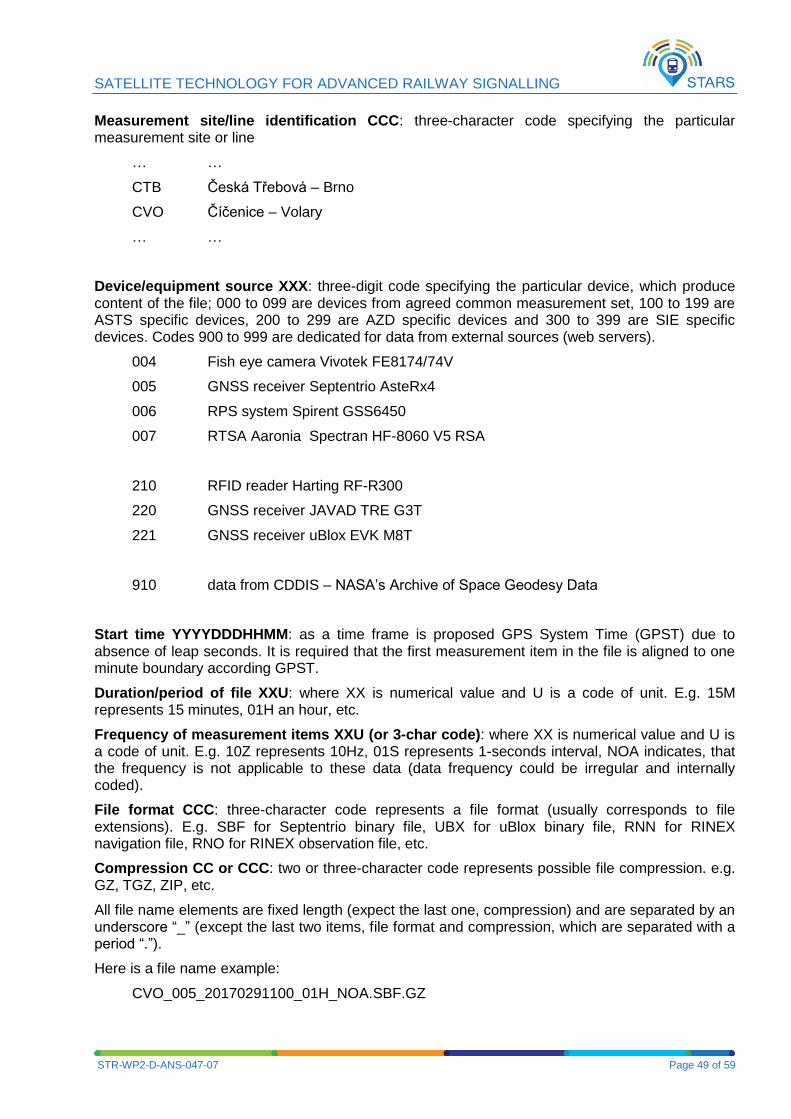
SATELLITE TECHNOLOGY FOR ADVANCED RAILWAY SIGNALLING
STR-WP2-D-ANS-047-07 Page 49 of 59
Measurement site/line identification CCC: three-character code specifying the particular measurement site or line
… …
CTB Česká Třebová – Brno
CVO Číčenice – Volary
… …
Device/equipment source XXX: three-digit code specifying the particular device, which produce content of the file; 000 to 099 are devices from agreed common measurement set, 100 to 199 are ASTS specific devices, 200 to 299 are AZD specific devices and 300 to 399 are SIE specific devices. Codes 900 to 999 are dedicated for data from external sources (web servers).
004 Fish eye camera Vivotek FE8174/74V
005 GNSS receiver Septentrio AsteRx4
006 RPS system Spirent GSS6450
007 RTSA Aaronia Spectran HF-8060 V5 RSA
210 RFID reader Harting RF-R300
220 GNSS receiver JAVAD TRE G3T
221 GNSS receiver uBlox EVK M8T
910 data from CDDIS – NASA’s Archive of Space Geodesy Data
Start time YYYYDDDHHMM: as a time frame is proposed GPS System Time (GPST) due to absence of leap seconds. It is required that the first measurement item in the file is aligned to one minute boundary according GPST.
Duration/period of file XXU: where XX is numerical value and U is a code of unit. E.g. 15M represents 15 minutes, 01H an hour, etc.
Frequency of measurement items XXU (or 3-char code): where XX is numerical value and U is a code of unit. E.g. 10Z represents 10Hz, 01S represents 1-seconds interval, NOA indicates, that the frequency is not applicable to these data (data frequency could be irregular and internally coded).
File format CCC: three-character code represents a file format (usually corresponds to file extensions). E.g. SBF for Septentrio binary file, UBX for uBlox binary file, RNN for RINEX navigation file, RNO for RINEX observation file, etc.
Compression CC or CCC: two or three-character code represents possible file compression. e.g. GZ, TGZ, ZIP, etc.
All file name elements are fixed length (expect the last one, compression) and are separated by an underscore “_” (except the last two items, file format and compression, which are separated with a period “.”).
Here is a file name example:
CVO_005_20170291100_01H_NOA.SBF.GZ
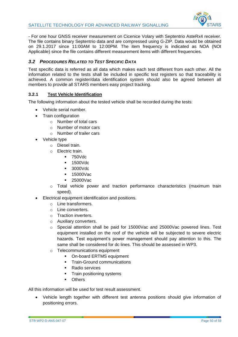
SATELLITE TECHNOLOGY FOR ADVANCED RAILWAY SIGNALLING
STR-WP2-D-ANS-047-07 Page 50 of 59
- For one hour GNSS receiver measurement on Cicenice Volary with Septentrio AsteRx4 receiver. The file contains binary Septentrio data and are compressed using G-ZIP. Data would be obtained on 29.1.2017 since 11:00AM to 12:00PM. The item frequency is indicated as NOA (NOt Applicable) since the file contains different measurement items with different frequencies.
3.2 PROCEDURES RELATED TO TEST SPECIFIC DATA
Test specific data is referred as all data which makes each test different from each other. All the information related to the tests shall be included in specific test registers so that traceability is achieved. A common register/data identification system should also be agreed between all members to provide all STARS members easy project tracking.
3.2.1 Test Vehicle Identification
The following information about the tested vehicle shall be recorded during the tests:
Vehicle serial number.
Train configuration
o Number of total cars
o Number of motor cars
o Number of trailer cars
Vehicle type
o Diesel train.
o Electric train.
750Vdc
1500Vdc
3000Vdc
15000Vac
25000Vac
o Total vehicle power and traction performance characteristics (maximum train
speed).
Electrical equipment identification and positions.
o Line transformers.
o Line converters.
o Traction inverters.
o Auxiliary converters.
o Special attention shall be paid for 15000Vac and 25000Vac powered lines. Test
equipment installed on the roof of the vehicle will be subjected to severe electric
hazards. Test equipment’s power management should pay attention to this. The
same shall be considered for dc lines. This should be assessed in WP3.
o Telecommunications equipment
On-board ERTMS equipment
Train-Ground communications
Radio services
Train positioning systems
Others
All this information will be used for test result assessment.
Vehicle length together with different test antenna positions should give information of
positioning errors.
SATELLITE TECHNOLOGY FOR ADVANCED RAILWAY SIGNALLING
STR-WP2-D-ANS-047-07 Page 51 of 59
A frequency management plan should be prepared for each vehicle in order to identify
possible intentional emitters within the vehicle.
For high speed vehicles pantograph bouncing and arc generation should be assessed. In this sense interfering signals could be generated in the pantograph-line contact.
3.2.2 Test Track Identification
The test tracks shall be identified and noted during the tests. The following lines should be covered, but should not be limited:
High speed lines
Urban lines
Topographically difficult lines (valleys, tunnels, forests)
The identification and definition process should be addressed in T2.3. Line specification with all geographical information including Eurobalises, geographical RFID tags, tunnels, bridges and possible obstacles such as roofs on a station should be covered.
3.2.3 Test Environment Conditions
Depending on the line and selected test tracks, the following items should be identified and noted for result assessment:
Presence of high/low buildings
Presence of natural obstacles
o Mountains
o Valleys
o Trees
o Others
Presence of man built obstacles
o Tunnels
o Electrified lines
o Others
Others
The test environment conditions should be identified on the test site itself and then related to the map. An updated map of the line should be used for the identification of any obstacles within the line. All these obstacles should be noted and characterised. A panoramic camera will help identify the test environment conditions. The following information could be useful:
GPS position of the obstacles, width, height and distance to the track.
Kilometric point within the line.
3.2.4 Weather Conditions
It is important to keep track of the atmospheric conditions during the tests. This is especially important since the weather conditions can directly affect propagation properties of the GNSS signals. The information related to the atmospheric conditions such as temperature, barometric pressure, humidity, altitude above sea level should be available together with the test results.
3.2.5 Geo-referencing Considerations
GPS and GLONASS use different reference frames: GPS uses WGS 84 and GLONASS PZ-90. This has to be taken into account if track cartography is going to be used. It is recommended to
SATELLITE TECHNOLOGY FOR ADVANCED RAILWAY SIGNALLING
STR-WP2-D-ANS-047-07 Page 52 of 59
stick to WGS 84. Geo-referencing of position is mandatory. Also, it has to be checked if cartography has been corrected with a local datum.
3.2.6 GNSS Service Performance Forecast for Campaign Scheduling
In order to optimise the effort, some GNSS service performance forecast will be carried out to set the most significant campaign testing periods and track locations. In this sense, GPS NAGUS should be consulted and EGNOS performance forecast reports should be requested from the ESSP for selected locations (e.g. to avoid, or be awared of, planned maintenance periods or expected service degradation events). Also some functionalities of EUROCONTROL AUGUR tool e.g. satellite visibility predictions tool (http://augur.ecacnav.com/augur/app/visibility) could be used. Also space weather forecasts could be obtained from http://www.swpc.noaa.gov/ (see http://www.swpc.noaa.gov/impacts/space-weather-and-gps-systems)
3.3 PROCEDURES RELATED TO STANDARDISED EQUIPMENT FOR GNSS PERFORMANCE
ASSESSMENT
The standardised equipment related to GNSS performance assessment includes:
1. GNSS antennas 2. GNSS splitters 3. GNSS RXs 4. GNSS RPS 5. VSA or modern spectrum analyser 6. Panoramic camera for sky visibility
3.3.1 GNSS antennas
GNSS antennas are to be placed in different locations on the train roof but have to satisfy installation standards.
3.3.2 RF splitters
RF splitters have to be checked in order to not filter the GNSS or desired frequencies in use. Depending on the equipment type (antenna, GNSS receiver, spectrum analyser, etc.) and RF splitters that are used (some inherently block DC), the use of DC blockers shall be evaluated in order not to damage equipment. It is recommended to close unused connections by a 50 Ohm resistance.
3.3.3 GNSS/SBAS receivers
GNSS receivers are mainly COTS/professional receivers and COTS modules to be connected to GNSS splitters. The navigation solutions should be relative to a specific reference frame.
The MCMF concept is still under development, compatibility and interoperability issues can pose uncertainties and can be not easy to handle. Therefore PVT information should be recorded using single constellations.
WAAS and SDCM do not cover EU territory
Configuration of Septentrio AsteRx4 professional GNSS receiver:
3.3.4 Spirent GNSS RPS or RF signal recorder
N.B. It is not possible to remotely turn on the Spirent GSS6425 RPS. You must always turn on the GSS6425 RPS using the front panel power button. For a step by step procedure of best use of this equipment refer to its datasheet.
SATELLITE TECHNOLOGY FOR ADVANCED RAILWAY SIGNALLING
STR-WP2-D-ANS-047-07 Page 53 of 59
a. Manually turn on the Spirent GNSS RPS and wait ten minutes before initiating the measurements in order for the OCXO clock to stabilize.
b. Connect one of the splitter outputs to the rear panel female SMA connector labelled “GNSS antenna” (make sure that only one equipment powers the active GNSS antenna, otherwise use DC blocks at the splitter output to avoid damage to other equipment)
c. Load the appropriate configuration file designed to record planned GNSS frequency bands (to include a citation to configuration files for GSS6425 and GSS6450 products)
3.3.5 VSA or Modern Real Time Spectrum Analyser Recorder
The on-board train electromagnetic environment has to be measured, in order to determine possible threats in terms of electromagnetic fields of the locomotive motors, AC/DC converter, catenary and/or sparks of the pantograph. In addition other external sources of malicious, uninformed or accidental jamming will be measured, such as but not limited to repeater devices or personal privacy devices (PPD-jammers).
The out-of-band interference spectrum monitoring with a wideband antenna (covering a range of 800 to 1900 MHz) as proposed in Test#5 from [3] covers in addition to the in-band interference test setup#4, jammers near or outside the GNSS frequency. It has to be noted that single frequency GNSS antennas have LNA with band-pass filters implemented, which will suppress most of the out-of-band interference. Therefore these out-of-band measurements are not representative for the interference effects to the GNSS receiver itself. On the other hand, multi-frequency GNSS antennas may be more exposed to such kind of out-of-band interference.
Installation rules:
For in-band interference measurements, the RTSA shall be connected to the OBU GNSS antennas through a power splitter covering the GNSS frequency range (not passing any DC signal). The splitter ensures the simultaneous recording of in-band interference measurements by the RTSA and GNSS info by GNSS receivers.
For out-of-band interference measurements, the RTSA shall be connected directly to the wideband antenna.
The spectrum analyser should collect recordings during the test movements along the test track.
The spectrum analyser should be able to scan parts of the spectrum between 1 GHz to 2 GHz, which includes GPS and Galileo L1, L5 frequency. The minimum signal levels to be detected should be at least -120.5 dBm. In the following, a resolution of 1000 sample / MHz per spectrum and an accuracy of the spectral power density better than +/-1dB are supposed.
GNSS frequencies in use should be configurable for in-band RFI measurement as proposed in test#4 from [3] for example:
GPS L1/Galileo E1, E1B, E1C Spectrum from 1.565 GHz to 1.585 GHz with 1.57542 GHz
GPS L1 center freq.
GPS L5/Galileo E5A&B from 1.164 GHz to 1.215 GHz with 1.17645 (E5A) and 1.20714
(E5B) centre
Galileo E6 from 1.260 GHz to 1.300 GHz with 1.27875 centre
Furthermore, the spectrum measurement should be compared to the ICAO interference mask, which characterizes the tolerable noise for standardised GPS receiver performance.
The spectrum measurements should be tagged with GPS time with a resolution of ms, in order to allow crosscheck for GPS-Signal-to-Noise influence. In order to time synchronize the spectrum analyser for each recorded spectrum data set, consisting of measurement {frequency, spectrum power} a time stamp should be recorded in order to geotag the spectrum data set. The TEKTRONIX RSA 306 seems to be suitable for the intended purpose to sample the spectrum (it
SATELLITE TECHNOLOGY FOR ADVANCED RAILWAY SIGNALLING
STR-WP2-D-ANS-047-07 Page 54 of 59
can also use the GNSS RX time reference clock or any reference clock input) and is able in post-processing to compare the spectrum data to a mask.
Interference data should only be recorded, if an interference mask is exceeded, in order to cope with the huge data volume (approx. 200MB/s)” E.g.: In order to get the interference detection false alarm rate of 1 event/day (ED114 requirement), resolution bandwidth should be chosen such that a margin of 17dB for measurement noise below the D0-229 interference mask of -120,5 dBm is reached. For this example, a resolution bandwidth of 3 KHz did reach this criterion. This matches also the intent to detect narrow band interference.
3.3.6 Camera or Video recorder
Information to assess any influence of the weather conditions [5] (e.g. weather on Earth: storms, snow, and space weather: solar wind, geomagnetic storms) needs to be gathered or downloaded from space weather prediction and monitoring centres. In addition to other data sources, a camera/video recorder allows to identify general weather phenomenon that may characterize the train environment. A video recorder may also be helpful to identify critical objects along the track and assess sky visibility. The video should be geotagged, or at least timed with UTC to be localizable via GNSS later.
3.4 PROCEDURES RELATED TO EGNOS DATA
In order to be in a position, if necessary one day, to adapt EGNOS algorithms to railway environment and expected service, and as documented in [4], it is necessary to capture all EGNOS information that could be needed to perform a replay with adapted EGNOS algorithms. For this purpose, it is necessary to record during the whole period of test:
- All (consolidated) GPS navigation messages received by EGNOS RIMS - All “raw measurements” made by all EGNOS RIMS A and RIMS B. This includes L1C/A,
L2P(Y) pseudo ranges as well as phase measurements, plus associated C/N0, plus other information
- All EGNOS generated corrections messages All this information shall be recorded at 1Hz. In order to be able to perform some replay, it is necessary to leave the necessary time for EGNOS algorithms to converge. For this purpose, it is necessary to start the EGNOS data capture at least 2 days before the experiment.
3.4.1 EDAS Service
One of the EGNOS services is the EDAS (EGNOS Data Access Service). This service, that requires a registration to be accessible allow retrieving all necessary information not older than two years. All information are available in RINEX 2.11 format. It is not necessary to perform the EDAS data collection in real-time, and in order to ease the coordination of activities, it is proposed to use the FTP access, few days after the on-board experiment.
3.4.2 Access to EDAS service
All necessary information is publicly available in EDAS Service Definition Document (SDD) which is available at version 2.1 by following this link: http://www.gsa.europa.eu/news/new-egnos-service-definition-document-released
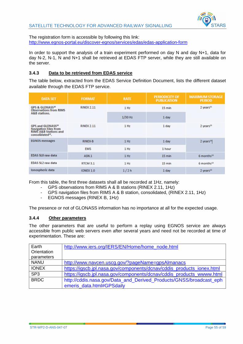
SATELLITE TECHNOLOGY FOR ADVANCED RAILWAY SIGNALLING
STR-WP2-D-ANS-047-07 Page 55 of 59
The registration form is accessible by following this link: http://www.egnos-portal.eu/discover-egnos/services/edas/edas-application-form In order to support the analysis of a train experiment performed on day N and day N+1, data for day N-2, N-1, N and N+1 shall be retrieved at EDAS FTP server, while they are still available on the server.
3.4.3 Data to be retrieved from EDAS service
The table below, extracted from the EDAS Service Definition Document, lists the different dataset
available through the EDAS FTP service.
From this table, the first three datasets shall all be recorded at 1Hz, namely: - GPS observations from RIMS A & B stations (RINEX 2.11, 1Hz) - GPS navigation files from RIMS A & B station, consolidated, (RINEX 2.11, 1Hz) - EGNOS messages (RINEX B, 1Hz)
The presence or not of GLONASS information has no importance at all for the expected usage.
3.4.4 Other parameters
The other parameters that are useful to perform a replay using EGNOS service are always accessible from public web servers even after several years and need not be recorded at time of experimentation. These are:
Earth Orientation parameters
http://www.iers.org/IERS/EN/Home/home_node.html
NANU http://www.navcen.uscg.gov/?pageName=gpsAlmanacs IONEX https://igscb.jpl.nasa.gov/components/dcnav/cddis_products_ionex.html SP3 https://igscb.jpl.nasa.gov/components/dcnav/cddis_products_wwww.html BRDC http://cddis.nasa.gov/Data_and_Derived_Products/GNSS/broadcast_eph
emeris_data.html#GPSdaily
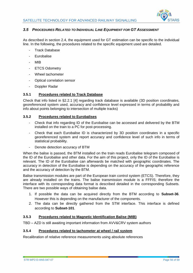
SATELLITE TECHNOLOGY FOR ADVANCED RAILWAY SIGNALLING
STR-WP2-D-ANS-047-07 Page 56 of 59
3.5 PROCEDURES RELATED TO INDIVIDUAL LINE EQUIPMENT FOR GT ASSESSMENT
As described in section 2.4, the equipment used for GT estimation can be specific to the individual line. In the following, the procedures related to the specific equipment used are detailed.
- Track Database
- Eurobalise
- MIB
- ETCS Odometry
- Wheel tachometer
- Optical correlation sensor
- Doppler Radar
3.5.1 Procedures related to Track Database
Check that info listed in §2.2.1 [4] regarding track database is available (3D position coordinates, georeferenced system used, accuracy and confidence level expressed in terms of probability and info about points belonging to intersection of multiple tracks)
3.5.2 Procedures related to Eurobalises
- Check that info regarding ID of the Eurobalise can be accessed and delivered by the BTM installed on the train to a PC for post-processing.
- Check that each Eurobalise ID is characterized by 3D position coordinates in a specific georeferenced system and report accuracy and confidence level of such info in terms of statistical probability.
- Denote detection accuracy of BTM
When the balise is passed, the BTM installed on the train reads Eurobalise telegram composed of the ID of the Eurobalise and other data. For the aim of this project, only the ID of the Eurobalise is relevant. The ID of the Eurobalise can afterwards be matched with geographic coordinates. The accuracy in detection of the Eurobalise is depending on the accuracy of the geographic reference and the accuracy of detection by the BTM.
Balise transmission modules are part of the European train control system (ETCS). Therefore, they are already installed on the trains. The balise transmission module is a FFFIS; therefore the interface with its corresponding data format is described detailed in the corresponding Subsets. There are two possible ways of obtaining balise data.
1. If possible the data can be acquired directly from the BTM according to Subset-36.
However this is depending on the manufacturer of the components.
2. The data can be directly gathered from the STM interface. This interface is defined
according to Subset-101.
3.5.3 Procedures related to Magnetic Identification Balise (MIB)
TBD – AZD is still awaiting important information from AVV&CRV system authors
3.5.4 Procedures related to tachometer at wheel / rail system
Recalibration of relative reference measurements using absolute references
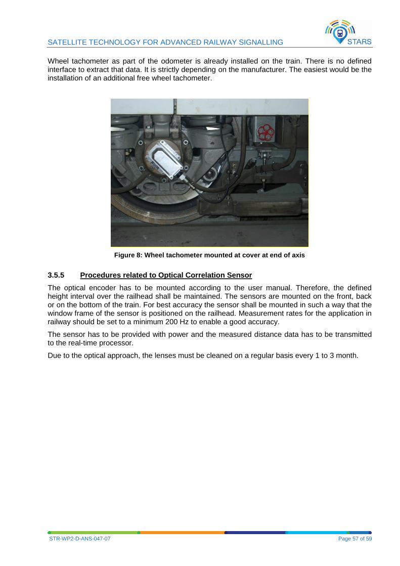
SATELLITE TECHNOLOGY FOR ADVANCED RAILWAY SIGNALLING
STR-WP2-D-ANS-047-07 Page 57 of 59
Wheel tachometer as part of the odometer is already installed on the train. There is no defined interface to extract that data. It is strictly depending on the manufacturer. The easiest would be the installation of an additional free wheel tachometer.
Figure 8: Wheel tachometer mounted at cover at end of axis
3.5.5 Procedures related to Optical Correlation Sensor
The optical encoder has to be mounted according to the user manual. Therefore, the defined height interval over the railhead shall be maintained. The sensors are mounted on the front, back or on the bottom of the train. For best accuracy the sensor shall be mounted in such a way that the window frame of the sensor is positioned on the railhead. Measurement rates for the application in railway should be set to a minimum 200 Hz to enable a good accuracy.
The sensor has to be provided with power and the measured distance data has to be transmitted to the real-time processor.
Due to the optical approach, the lenses must be cleaned on a regular basis every 1 to 3 month.
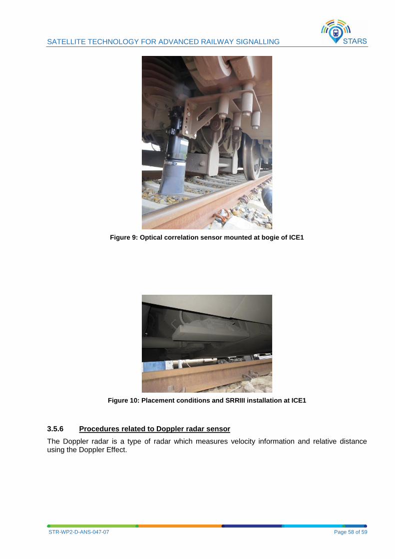
SATELLITE TECHNOLOGY FOR ADVANCED RAILWAY SIGNALLING
STR-WP2-D-ANS-047-07 Page 58 of 59
Figure 9: Optical correlation sensor mounted at bogie of ICE1
Figure 10: Placement conditions and SRRIII installation at ICE1
3.5.6 Procedures related to Doppler radar sensor
The Doppler radar is a type of radar which measures velocity information and relative distance using the Doppler Effect.
SATELLITE TECHNOLOGY FOR ADVANCED RAILWAY SIGNALLING
STR-WP2-D-ANS-047-07 Page 59 of 59
4 REFERENCES
[1] STARS Grant Agreement, Annex I - “Innovation Action”, 25th of November 2015.
[2] STARS Consortium Agreement of 6th November 2015.
[3] ERSAT EAV consortium, D3.1 - Test procedure and specification of the on-field measurement campaign ERSAT-EAV-A-4-000-02
[4] STARS D2.1 Specification of the Measurement Information STR-WP2-D-ANS-021-09 created on 11 November 2016
[5] STARS Sealed Proposal; Call:H2020-Galileo-2015-1, Proposal: 687414, 08/04/2015 16:22:43 CET
[6] UNISIG, “SUBSET-036 3.0.0 FFFIS for Eurobalise.” 2012
[7] STARS D2.3 Identification of the Representative Railway Lines/Sites STR-WP2-D-ANS-048-04 created on 06 October 2016
[8] STARS Technical note “Common Minimal Set of Equipment” STR-WP2-T-ANS-049-01 created on 10 October 2016