d-subminiature connectors catalog...2 d-submiiature connectors information industrial introduction...
TRANSCRIPT

belfuse.com/cinch
D-Subminiature Connectors Catalog
INDUSTRIAL

2
D-SUBMINIATURE CONNECTORS INFORMATION INDUSTRIALIntroduction
The D-subminiature is one of the most popular styles of connectors in the I/O category. It is used in
computer, telecom, datacom, medical, and test instrumentation applications as well as in the military and
aerospace fields.
Types of D-subminiature connectors manufactured by Cinch
� Printed Circuit Board connectors:• Vertical connectors for panel mounting with Dip Solder PC tails.
• Right-Angle connectors for board mounting with Dip Solder PC tails.
� Connectors for cable assemblies or wire harnesses:• Crimp and Poke.
• Solder Cup.
• Insulation Displacement (IDC) to terminate discrete wire.
• Wire Wrap.
How to read this section
� The information pages provide standard data common to all D-subminiature connectors. These include:• D-subminiature contact arrangements - see page 4.
• Panel mounting specifications/hardware - see page 5.
• D-subminiature shell dimensions - see page 6.
• PCB thickness chart and PCB layout dimensions - see page 7.
� D-subminiature pages are grouped by series. A series is a family of connectors with a similar performance level. Each series shares a set of features and specifications, from economical and commercial grade product to high-reliability and military connectors. Each series begins with a page outlining general features and specifications of connectors, followed by the pages on individual connectors with drawings or features specific to that connector. Drawings reflect clarifications of dimensions not called out in the information pages of this catalog.
� Accessories including backshells, junction shells, and hoods as well as hardware can be found on pages 34 thru 50.
� Termination tooling for Cinch connectors can be found at the end of the D-subminiature catalog.

3
belfuse.com/cinch
INDUSTRIALD-SUBMINIATURE CONNECTORS INFORMATION
General Information
� All connectors are intermateable with any Cinch D-subminiature of comparable pin count and density, or the D-sub connector of any other manufacturer complying dimensionally with MIL-C-24308.
� Solder terminations and boardlocks meet the requirements for solderability in accordance with MIL-STD-202, Method 208.
� DURABILITY• Mated connectors are subjected to cycles of insertions and withdrawals specified on the catalog page. After the prescribed
cycles the connectors will meet the Cinch requirements concerning insertion withdrawal force, individual contact insertion-
withdrawal force, and contact resistance.
� APPROVALS• Most Cinch connectors have UL recognition and CSA approval; however, the specific approvals are listed on the individual
catalog pages.
� CONTACTS• Cinch connector contacts are generally offered in Gold Flash or 30μin. gold plating for commercial product, and 50μin. gold
plating for M24308 Series Military D-subminiature connectors.
• Cinch connectors utilize economical stamped and formed contacts and/or screw machine contacts for enhanced perfor-
mance.
• Standard density connectors utilize size 20 contacts.
� METAL SHELLS• Commercial-grade steel shells are usually available in zinc plating with yellow or clear chromate finish or tin plating.
• Tin-plated plugs have grounding indents.
• Military grade M24308 Series connector shells are generally steel cadmium plating and yellow chromate finish.
• Insulator materials are glass-filled polyester, glass-filled nylon, and diallyl phthalate.
� The connectors are usually available in plugs and sockets in 9, 15, 25, 37, and 50 position sizes.
Introduction

4
D-SUBMINIATURE CONNECTORS INFORMATION INDUSTRIALIntroduction
Printed Circuit Board Connectors
� Cinch provides connectors in various footprints, contact diameters, and lengths in both vertical and right-angle PC mount styles with dip solder tails.
� Cinch PCB connectors have metal shells.
Connectors for Terminating Cable Wire
� Wire Wrap connectors are available in two tail lengths for two-wrap and three-wrap terminations. The contact is terminated by wrapping wire around it using a wire wrap gun. This connector is especially useful for prototyping since the wire can be unwrapped and rewrapped if necessary.
� Solder Cup connectors allow reliable long-term termination by soldering the wire directly into the connector contact. Cinch Solder Cups accommodate up to 20 AWG wire.
� Crimp and Poke connectors allow the wire to be terminated more economically than wire wrap or solder cup styles. Contacts are crimped and inserted into the connector. In our D*U Series, the contact is crimped around the conductor wire. Crimp and Poke connectors can be selectively loaded to save labor and material cost.
Standard Density Plug Inserts
4-5 Call Toll Free: 1 (800) 323-9612
4
D-subminiature ConnectorsInformation
IntroductionContact Arrangements
NOTE: Mating face of plug is shown; socket is mirror image.
Standard Density Plug Inserts
1.5 Density Plug Inserts
Contact Arrangements

5
belfuse.com/cinch
INDUSTRIALD-SUBMINIATURE CONNECTORS INFORMATIONIntroductionShells and Mounts
4-6
4
D-subminiature ConnectorsInformation
Panel Mounting Specifications
Dimensions
Mounting MethodShell Front/ A B C D E F HSize Positions Rear Panel in mm in mm in mm in mm in mm in mm in mm
Front 0.98 24.89 0.49 12.45 0.87 22.10 0.44 11.18 0.51 12.95 0.26 6.60 0.08 2.03E 9 Rear 0.98 24.89 0.49 12.45 0.81 20.57 0.40 10.16 0.45 11.43 0.23 5.84 0.13 3.30Front 1.31 33.27 0.66 16.76 1.10 27.94 0.60 15.24 0.51 12.95 0.26 6.60 0.08 2.03A 15 Rear 1.31 33.27 0.66 16.76 1.13 28.70 0.57 14.48 0.45 11.43 0.23 5.84 0.13 3.30Front 1.85 46.99 0.93 23.62 1.74 44.20 0.87 22.10 0.51 12.95 0.26 6.60 0.08 2.03B 25 Rear 1.85 46.99 0.93 23.62 1.67 42.42 0.84 21.34 0.45 11.43 0.23 5.84 0.13 3.30Front 2.50 63.50 1.25 31.75 2.39 60.71 1.20 30.48 0.51 12.95 0.26 6.60 0.08 2.03C 37 Rear 2.50 63.50 1.25 31.75 2.33 59.18 1.16 29.46 0.45 11.43 0.23 5.84 0.13 3.30Front 2.41 61.21 1.20 30.48 2.30 58.42 1.15 29.21 0.62 15.75 0.31 6.60 0.08 2.03D 50 Rear 2.41 61.21 1.20 30.48 2.22 56.39 1.11 28.19 0.56 14.22 0.28 5.84 0.13 3.30
PANEL MOUNTING HARDWARE: Aids in alignment of plug and receptacle.Float Bushing
Reverse Float Bushing
Floating Dual Bushing
4-40 Clinch Nut
Rear panel mounting
Rear panel mountingFront and rear panel mounting
Front panel mounting
IntroductionShells and Mounts
Call Toll Free: 1 (800) 323-9612
Panel Mounting Specifications
Dimensions
Mounting Method
Shell Size
Positions Front/Rear Panel
A B C D E F H
in mm in mm in mm in mm in mm in mm in mm
E 9 FrontRear
0.980.98
24.8924.89
0.490.49
12.4512.45
0.870.81
22.1020.57
0.440.40
11.1810.16
0.510.45
12.9511.43
0.260.23
6.605.84
0.080.13
2.033.30
A 15 FrontRear
1.311.31
33.2733.27
0.660.66
16.7616.76
1.101.13
27.9428.70
0.600.57
15.2414.48
0.510.45
12.9511.43
0.260.23
6.605.84
0.080.13
2.033.30
B 25 FrontRear
1.851.85
46.9946.99
0.930.93
23.6223.62
1.741.67
44.2042.42
0.870.84
22.1021.34
0.510.45
12.9511.43
0.260.23
6.605.84
0.080.13
2.033.30
C 37 FrontRear
2.502.50
63.5063.50
1.251.25
31.7531.75
2.392.33
60.7159.18
1.201.16
30.4829.46
0.510.45
12.9511.43
0.260.23
6.605.84
0.080.13
2.033.30
D 50 FrontRear
2.412.41
61.2161.21
1.201.20
30.4830.48
2.302.22
58.4256.39
1.151.11
29.2128.19
0.620.56
15.7514.22
0.310.28
6.605.84
0.080.13
2.033.30
PANEL MOUNTING HARDWARE: Aids in alignment of plug and receptacle.
Float Bushing
4-6
4
D-subminiature ConnectorsInformation
Panel Mounting Specifications
Dimensions
Mounting MethodShell Front/ A B C D E F HSize Positions Rear Panel in mm in mm in mm in mm in mm in mm in mm
Front 0.98 24.89 0.49 12.45 0.87 22.10 0.44 11.18 0.51 12.95 0.26 6.60 0.08 2.03E 9 Rear 0.98 24.89 0.49 12.45 0.81 20.57 0.40 10.16 0.45 11.43 0.23 5.84 0.13 3.30Front 1.31 33.27 0.66 16.76 1.10 27.94 0.60 15.24 0.51 12.95 0.26 6.60 0.08 2.03A 15 Rear 1.31 33.27 0.66 16.76 1.13 28.70 0.57 14.48 0.45 11.43 0.23 5.84 0.13 3.30Front 1.85 46.99 0.93 23.62 1.74 44.20 0.87 22.10 0.51 12.95 0.26 6.60 0.08 2.03B 25 Rear 1.85 46.99 0.93 23.62 1.67 42.42 0.84 21.34 0.45 11.43 0.23 5.84 0.13 3.30Front 2.50 63.50 1.25 31.75 2.39 60.71 1.20 30.48 0.51 12.95 0.26 6.60 0.08 2.03C 37 Rear 2.50 63.50 1.25 31.75 2.33 59.18 1.16 29.46 0.45 11.43 0.23 5.84 0.13 3.30Front 2.41 61.21 1.20 30.48 2.30 58.42 1.15 29.21 0.62 15.75 0.31 6.60 0.08 2.03D 50 Rear 2.41 61.21 1.20 30.48 2.22 56.39 1.11 28.19 0.56 14.22 0.28 5.84 0.13 3.30
PANEL MOUNTING HARDWARE: Aids in alignment of plug and receptacle.Float Bushing
Reverse Float Bushing
Floating Dual Bushing
4-40 Clinch Nut
Rear panel mounting
Rear panel mountingFront and rear panel mounting
Front panel mounting
IntroductionShells and Mounts
Call Toll Free: 1 (800) 323-9612
4-40 Clinch Nut
Rear panel mounting
Rear panel mounting

6
D-SUBMINIATURE CONNECTORS INFORMATION INDUSTRIAL
Two Holes.120 + .005 (3.05 + 0.13) Dia.
4
4-7
Mating Side Termination Side
A +.015" B +.010" B1 +.005" C +.005" D +.010" D1 +.010" E +.010"Shell Connector (0.38mm) (0.25mm) (0.13 mm) (0.13mm) (0.25mm) (0.25mm) (0.25mm)Size Positions Type in mm in mm in mm in mm in mm in mm in mm
E 9 Plug 1.213 30.81 -- -- .666 16.90 0.984 24.99 -- -- .329 8.40 .494 12.55Socket 1.213 30.81 .640 16.26 -- -- 0.984 24.99 .308 7.82 -- -- .494 12.55
A 15 Plug 1.541 39.14 -- --- .994 25.30 1.312 33.32 -- --- .329 8.40 .494 12.55Socket 1.541 39.14 .968 24.59 -- -- 1.312 33.32 .308 7.82 -- -- .494 12.55
B 25 Plug 2.088 53.04 -- -- 1.534 39.00 1.852 47.04 -- -- .329 8.40 .494 12.55Socket 2.088 53.04 1.508 38.30 -- -- 1.852 47.04 .308 7.82 -- -- .494 12.55
C 37 Plug 2.729 69.32 -- --- 2.182 55.40 2.500 63.50 -- --- .329 8.40 .494 12.55Socket 2.729 69.32 2.156 54.76 -- -- 2.500 63.50 .308 7.82 -- --- .494 12.55
D 50 Plug 2.635 66.93 -- -- 2.079 52.80 2.406 61.11 -- -- .436 11.07 .605 15.37Socket 2.635 66.93 2.062 52.34 -- -- 2.406 61.11 .420 10.67 -- -- .605 15.37
G +.010" H +.010" J +.010" K +.005" L +.010" M +.010"Shell Connector (0.25mm) (0.25mm) (0.25 mm) (0.25mm) (0.25mm) (0.25mm)Size Positions Type in mm in mm in mm in mm in mm in mm
E 9 Plug .759 19.28 .422 10.72 .030 0.76 .236 5.99 .045 1.14 .422 10.72Socket .759 19.28 .422 10.72 .030 0.76 .243 6.17 .045 1.14 .429 10.92
A 15 Plug 1.083 27.51 .422 10.72 .030 0.76 .236 5.99 .045 1.14 .422 10.72Socket 1.083 27.51 .422 10.72 .030 0.76 .253 6.17 .045 1.14 .429 10.92
B 25 Plug 1.625 41.27 .422 10.72 .039 0.99 .231 5.87 .060 1.52 .426 10.82Socket 1.625 41.27 .422 10.72 .030 0.76 .243 6.17 .045 1.14 .429 10.92
C 37 Plug 2.272 57.71 .422 10.72 .039 0.99 .231 5.87 .060 1.52 .426 10.82Socket 2.272 57.71 .422 10.72 .030 0.76 .243 6.17 .045 1.14 .429 10.92
D 50 Plug 2.178 55.32 .534 13.56 .039 0.99 .231 5.87 .060 1.52 .426 10.82Socket 2.178 55.32 .534 13.56 .030 0.76 .243 6.17 .045 1.14 .429 10.92
B and D are outside dimensions for socket. D and B are inside dimensions for plug.
D-subminiature ConnectorsInformation
IntroductionShells and Mounts
Call Toll Free: 1 (800) 323-9612
IntroductionShells and Mounts
A ± .015"(0.38mm)
B ± .010"(0.25mm)
B1 ± .005"(0.13mm)
C ± .005"(0.13mm)
D ± .010"(0.25mm)
D1 ± .010"(0.25mm)
E ± .010"(0.25mm)Shell
SizePositions Connector
Typein mm in mm in mm in mm in mm in mm in mm
E 9 PlugSocket
1.2131.213
30.8130.81
--.640
--16.26
.666--
16.90--
0.9840.984
24.9924.99
--.308
--7.82
.329--
8.40--
.494
.49412.5512.55
A 15 PlugSocket
1.5411.541
39.1439.14
--.968
--24.59
.994--
25.30--
1.3121.312
33.3233.32
--.308
--7.82
.329--
8.40--
.494
.49412.5512.55
B 25 PlugSocket
2.0882.088
53.0453.04
--1.508
--38.30
1.534--
39.00 1.8521.852
47.0447.04
--.308
--7.82
.329--
8.40--
.494
.49412.5512.55
C 37 PlugSocket
2.7292.729
69.3269.32
--2.156
--54.76
2.182--
55.40--
2.5002.500
63.5063.50
--.308
--7.82
.329--
8.40--
.494
.49412.5512.55
D 50 PlugSocket
2.6352.635
66.9366.93
--2.062
--52.34
2.079--
52.80--
2.4062.406
61.1161.11
--.420
--10.67
.436--
11.07--
.605
.60515.3715.37
G ± .010"(0.25mm)
H ± .010"(0.25mm)
J ± .010"(0.25mm)
K ± .005"(0.25mm)
L ± .010"(0.25mm)
M ± .010"(0.25mm)Shell
SizePositions Connector
Typein mm in mm in mm in mm in mm in mm
E 9 PlugSocket
.759
.75919.2819.28
.422
.42210.7210.72
0.300.30
0.760.76
.236
.2435.996.17
0.450.45
1.141.14
.422
.42910.7210.92
A 15 PlugSocket
1.0831.083
27.5127.51
.422
.42210.7210.72
0.300.30
0.760.76
.236
.2365.996.17
.045
.0451.141.14
.422
.42910.7210.92
B 25 PlugSocket
1.6251.625
41.2741.27
.422
.42210.7210.72
0.390.30
0.990.76
.231
.2435.876.17
.060
.0451.521.14
.426
.42910.8210.92
C 37 PlugSocket
2.2722.272
57.7157.71
.422
.42210.7210.72
0.390.30
0.990.76
.231
.2435.876.17
.060
.0451.521.14
.426
.42910.8210.92
D 50 PlugSocket
2.1782.178
55.3255.32
.534
.53413.5613.56
.039
.0300.990.76
.231
.2435.876.17
.060
.0451.521.14
.426
.42910.8210.92
Mating side Termination Side

7
belfuse.com/cinch
INDUSTRIALD-SUBMINIATURE CONNECTORS INFORMATIONIntroductionPrinted Circuit Board Layout Hole Dimensions
Standard Density D-subminiature
Mounting Dimensions Board Layouts
Footprints (Component side shown)
4
4-8
D-subminiature ConnectorsInformation
IntroductionPrinted Circuit BoardLayout Hole Dimensions
Standard Density D-subminiatureMounting Dimensions Board LayoutsFootprints (Component side shown)
9 PositionShell Size E
25 PositionShell Size B
15 PositionShell Size A
The footprints on this page are standard for all metalshell D-subminiature connectors.
On all right-angle D-subminiature connectors, the short row of contacts is positioned closest to the edge of the board.
PC Board Lead Hole Size
Terminal Dia. Hole Dia.in mm in mm
.040 1.02 .055 1.40
.030 0.76 .045 1.14
.024-.025 0.61-0.64 .039 0.99
Call Toll Free: 1 (800) 323-9612
15X
25X
9 Position Shell Size E
25 Position Shell Size B
15 Position Shell Size A
The footprints on this page are standard for all metal shell D-subminiature connectors.
On all right-angle D-subminiature connectors, the short row of contacts is positioned closest to the edge
of the board.
PC Board Lead Hole Size
Terminal in
Dia.
mm
Hole Dia.
in mm
.040 1.02 .055 1.40
.030 0.76 .045 1.14
.024-.025 0.61-0.64 .039 0.99

8
D-SUBMINIATURE CONNECTORS INFORMATION INDUSTRIALIntroductionPrinted Circuit Board Layout Hole Dimensions
Standard Density D-subminiature
Mounting Dimensions Board Layouts
Footprints (Component side shown)
4-9 Call Toll Free: 1 (800) 323-9612
4
D-subminiature ConnectorsInformation
IntroductionPrinted Circuit BoardLayout Hole Dimensions
50 PositionShell Size D
37 PositionShell Size C
Standard Density D-subminiatureMounting Dimensions Board LayoutsFootprints (Component side shown)
The footprints on this page are standard for all metalshell D-subminiature connectors.
On all right-angle D-subminiature connectors, the short row of contacts is positioned closest to the edge of the board.
PC Board Lead Hole Size
Terminal Dia. Hole Dia.in mm in mm
.040 1.02 .055 1.40
.030 0.76 .045 1.14
.024-.025 0.61-0.64 .039 0.99
37 Position Shell Size C
50 Position Shell Size D
The footprints on this page are standard for all metal shell
D-subminiature connectors.
On all right-angle D-subminiature connectors, the short row
of contacts is positioned closest to the edge of the board.
PC Board Lead Hole Size
Terminal in
Dia.
mm
Hole Dia.
in mm
.040 1.02 .055 1.40
.030 0.76 .045 1.14
.024-.025 0.61-0.64 .039 0.99

9
belfuse.com/cinch
INDUSTRIAL
Features
� Offered in 9, 15, 25, 37, and 50 position plugs and sockets
� Available with gold flash or 30μin. gold plating.
� Offered with 0.120 mounting holes and optional 4-40 clinch nuts.
� Approvals:• UL Recognized - Files E170218 (UL1977) and E130965 (UL1863).
• CSA Approved - File LR31996.
� See pages 5-6 for standard dimensions, contact arrangements, and panel mounting specifications.
4-26Call Toll Free: 1 (800) 323-9612
FEA
TURE
S
■ Offered in 9, 15, 25, 37, and 50 position plugs and sockets (except right-angle PCB connectors-9 , 15, and 25 positions).
■ Available with gold flash or 30µin. gold plating.■ Offered with .120 mounting holes, optional 4-40 clinch nuts, or dual float bushings (except right-
angle PCB connectors-mounting holes only).■ Approvals:
• UL Recognized - Files E170218 (UL1977) and E130965 (UL1863).• CSA Approved - File LR31996.
■ See pages 4-5 thru 4-10 for standard dimensions, contact arrangements, and panel mounting specifications.
MA
TERI
ALS
Insulator Material: Glass-filled nylon (black), UL 94 V-O ratedConnector Shell: Steel with zinc plating and yellow chromate
finish or tin plating (grounding indents on plug)
4-40 Clinch Nut: Steel with cadmium plating and yellowchromate finish
Dual Float Bushing: Stainless steel, passivated
ENV
IRO
NM
ENTA
L Operating Temperature: -65°C to + 125°CShock: 50G peak per MIL-STD-202, Method 213, Condition GVibration: 12 cycles in three perpendicular directions @
10-2000Hz, per MIL-STD-202, Method 204, Condition D
Moisture Resistance: 90-95% relative humidity @ 40°C for96 hours per MIL-STD-202, Method 103
ELEC
TRIC
AL
Withstanding Voltage: Minimum 1000V RMS @ sea level
Current Rating: 5 Amps
Contact Resistance: 2.7 milliohms maximum
Insulation Resistance: 5000 megohms maximum
(initial); 1000 megohms (minimum)
after environmental testing
MEC
HA
NIC
AL
Individual Contact Insertion and Separation Force (minimum/maximum): 0.7 oz./12 oz.
Durability: 500 mating cycles
D-subminiature Metal Shell Crimp and Poke, Right-Angle and Vertical PCBD*U Series
Materials
Insulator Material Glass-filled nylon (black), UL 94 V-O rated
Connector Shell Steel with zinc plating and yellow chromate finish or clear for RoHS or tin plating (grounding indents on plug)
4-40 Clinch Nut Steel with cadmium plating and yellow chromate finish
Dual Float Bushing Stainless steel, passivated
EnvironmentalOperating Temperature -65°C to +105°C
Shock 50G peak per MIL-STD-202, Method 213, Condition G
Vibration 12 cycles in three perpendicular directions @ 10-2000Hz, per MIL-STD-202, Method 204, Condition D
Moisture Resistance 90-95% relative humidity @ 40ºC for 96 hours per MIL-STD-202, Method 103
Electrical Withstanding Voltage Minimum 1000V RMS @ sea level
Current Rating 5 Amps
Contact Resistance 2.7 milliohms maximum
Insulation Resistance 5000 megohms minimum (initial); 1000 megohms (minimum) after environmental testing
MechanicalIndividual Contact Insertion and Separation Force
0.7 oz. minimum/12oz. maximum
Durability 500 mating cycles
D-SUBMINIATURE METAL SHELL CRIMP AND POKE
4-26Call Toll Free: 1 (800) 323-9612
FEA
TURE
S
■ Offered in 9, 15, 25, 37, and 50 position plugs and sockets (except right-angle PCB connectors-9 , 15, and 25 positions).
■ Available with gold flash or 30µin. gold plating.■ Offered with .120 mounting holes, optional 4-40 clinch nuts, or dual float bushings (except right-
angle PCB connectors-mounting holes only).■ Approvals:
• UL Recognized - Files E170218 (UL1977) and E130965 (UL1863).• CSA Approved - File LR31996.
■ See pages 4-5 thru 4-10 for standard dimensions, contact arrangements, and panel mounting specifications.
MA
TERI
ALS
Insulator Material: Glass-filled nylon (black), UL 94 V-O ratedConnector Shell: Steel with zinc plating and yellow chromate
finish or tin plating (grounding indents on plug)
4-40 Clinch Nut: Steel with cadmium plating and yellowchromate finish
Dual Float Bushing: Stainless steel, passivated
ENV
IRO
NM
ENTA
L Operating Temperature: -65°C to + 125°CShock: 50G peak per MIL-STD-202, Method 213, Condition GVibration: 12 cycles in three perpendicular directions @
10-2000Hz, per MIL-STD-202, Method 204, Condition D
Moisture Resistance: 90-95% relative humidity @ 40°C for96 hours per MIL-STD-202, Method 103
ELEC
TRIC
AL
Withstanding Voltage: Minimum 1000V RMS @ sea level
Current Rating: 5 Amps
Contact Resistance: 2.7 milliohms maximum
Insulation Resistance: 5000 megohms maximum
(initial); 1000 megohms (minimum)
after environmental testing
MEC
HA
NIC
AL
Individual Contact Insertion and Separation Force (minimum/maximum): 0.7 oz./12 oz.
Durability: 500 mating cycles
D-subminiature Metal Shell Crimp and Poke, Right-Angle and Vertical PCBD*U Series

10
INDUSTRIALD-SUBMINIATURE METAL SHELL CRIMP AND POKE D*U SERIES
INDUSTRIAL
� Machined contacts supplied loose with connector or can be ordered separately. Use with 20-24 AWG wire.
Termination Tooling
� Contact Insertion/Extraction: #CIET-20-HDB. See page 51.
� Loose Contact Crimp Tool:
Machined Contact - #M22520/2-01. See page 51.
For Positioner as required - EP-580. See page 51.
Materials
Contact Material Plug - Brass (stamped) or copper alloy (machined). Socket - Phosphor bronze (stamped) copper alloy (machined).
Contact Plating Machined Plugs and Sockets: Golf flash or 30μin. gold. All over nickel

11
belfuse.com/cinch
INDUSTRIAL
belfuse.com/cinch
INDUSTRIAL
4-28
4
Call Toll Free: 1 (800) 323-9612
D-subminiature Metal Shell Crimp and Poke D*U Series
Zinc-Plated Shell with Yellow Chromate FinishMounting Holes 4-40 Clinch Nuts Dual Float Bushings
Contacts Without Contacts Without Contacts Without Position Included Contacts Included Contacts Included Contacts
9 DEU-9S DEU-9S-FO DEUE-9S DEUE-9S-FO DEUY-9S DEUY-9S-FO 15 DAU-15S DAU-15S-FO DAUE-15S DAUE-15S-FO DAUY-15S DAUY-15S-FO25 DBU-25S DBU-25S-FO DBUE-25S DBUE-25S-FO DBUY-25S DBUY-25S-FO37 DCU-37S DCU-37S-FO DCUE-37S DCUE-37S-FO DCUY-37S DCUY-37S-FO 50 DDU-50S DDU-50S-FO DDUE-50S DDUE-50S-FO DDUY-50S DDUY-50S-FO
D*U Crimp and Poke Sockets
Tin-Plated Shell Mounting Holes 4-40 Clinch Nuts Dual Float Bushings
Contacts Without Contacts Without Contacts Without Position Included Contacts Included Contacts Included Contacts
9 DEU-9ST DEU-9ST-FO DEUE-9ST DEUE-9ST-FO DEUY-9ST DEUY-9ST-FO15 DAU-15ST DAU-15ST-FO DAUE-15ST DAUE-15ST-FO DAUY-15ST DAUY-15ST-FO25 DBU-25ST DBU-25ST-FO DBUE-25ST DBUE-25ST-FO DBUY-25ST DBUY-25ST-FO37 DCU-37ST DCU-37ST-FO DCUE-37ST DCUE-37ST-FO DCUY-37ST DCUY-37ST-FO50 DDU-50ST DDU-50ST-FO DDUE-50ST DDUE-50ST-FO DDUY-50ST DDUY-50ST-FO
Zinc-Plated Shell with Yellow Chromate FinishMounting Holes 4-40 Clinch Nuts Dual Float Bushings
Contacts Without Contacts Without Contacts Without Position Included Contacts Included Contacts Included Contacts
9 DEU-9P DEU-9P-FO DEUE-9-P DEUE-9P-FO DEUY-9P DEUY-9P-FO 15 DAU-15P DAU-15P-FO DAUE-15-P DAUE-15-P-FO DAUY-15P DAUY-15P-FO25 DBU-25P DBU-25P-FO DBUE-25-P DBUE-25P-FO DBUY-25P DBUY-25P-FO 37 DCU-37P DCU-37P-FO DCUE-37-P DCUE-37P-FO DCUY-37P DCUY-37P-FO50 DDU-50P DDU-50P-FO DDUE-50-P DDUE-50P-FO DDUY-50P DDUY-50P-FO
Tin-Plated Shell with Grounding IndentsMounting Holes 4-40 Clinch Nuts Dual Float Bushings
Contacts Without Contacts Without Contacts Without Position Included Contacts Included Contacts Included Contacts
9 DEU-9PTI DEU-9PTI-FO DEUE-9PTI DEUE-9PTI-FO DEUY-9PTI DEUY-9PTI-FO15 DAU-15PTI DAU-15PTI-FO DAUE-15PTI DAUE-15PTI-FO DAUY-15PTI DAUY-15PTI-FO25 DBU-25PTI DBU-25PTI-FO DBUE-25PTI DBUE-25PTI-FO DBUY-25PTI DBUY-25PTI-FO37 DCU-37PTI DCU-37PTI-FO DCUE-37PTI DCUE-37PTI-FO DCUY-37PTI DCUY-37PTI-FO50 DDU-50PTI DDU-50PTI-FO DDUE-50PTI DDUE-50PTI-FO DDUY-50PTI DDUY-50PTI-FO
D*U Crimp and Poke Plugs
Ordering Information
Yellow Chromate RoHS Compliant with Clear Chromate
Mounting Holes 4-40 Clinch Nuts Mounting Holes 4-40 Clinch Nuts
Positions Contacts Included
Without Contacts
Contacts Included
Without Contacts
Contacts Included
Without Contacts
Contacts Included
Without Contacts
9 DEU-9P DEU-9P-FO DEUE-9P DEUE-9P-FO DEUH-9P DEUH-9P-FO DEUEH-9P DEUEH-9P-FO
15 DAU-15P DAU-15P-FO DAUE-15P DAUE-15-P-FO DAUH-15P DAUH-15P-FO DAUEH-15P DAUEH-15P-FO
25 DBU-25P DBU-25P-FO DBUE-25P DBUE-25P-FO DBUH-25P DBUH-25P-FO DBUEH-25P DBUEH-25P-FO
37 DCU-37P DCU-37P-FO DCUE-37P DCUE-37P-FO DCUH-37P DCUH-37P-FO DCUEH-37P DCUEH-37P-FO
50 DDU-50P DDU-50P-FO DDUE-50P DDUE-50P-FO DDUH-50P DDUH-50P-FO DDUEH-50P DDUEH-50P-FO
Ordering Information
D*U Crimp and Poke Plugs
Tin-Plated Shell with Grounding IndentsMounting Holes 4-40 Clinch Nuts
Positions Contacts Included
Without Contacts
Contacts Included
Without Contacts
9 DEU-9PTI DEU-9PTI-FO DEUE-9-PTI DEUE-9PTI-FO
15 DAU-15PTI DAU-15PTI-FO DAUE-15-PTI DAUE-15PTI-FO
25 DBU-25PTI DBU-25PTI-FO DBUE-25-PTI DBUE-25PTI-FO
37 DCU-37PTI DCU-37PTI-FO DCUE-37-PTI DCUE-37PTI-FO
50 DDU-50PTI DDU-50PTI-FO DDUE-50-PTI DDUE-50PTI-FO
Yellow Chromate RoHS Compliant
Mounting Holes 4-40 Clinch Nuts Mounting Holes 4-40 Clinch Nuts
Positions Contacts Included
Without Contacts
Contacts Included
Without Contacts
Contacts Included
Without Contacts
Contacts Included
Without Contacts
9 DEU-9S DEU-9S-FO DEUE-9S DEUE-9S-FO DEUH-9S DEUH-9S-FO DEUEH-9S DEUEH-9S-FO
15 DAU-15S DAU-15S-FO DAUE-15S DAUE-15S-FO DAUH-15S DAUH-15S-FO DAUEH-15S DAUEH-15S-FO
25 DBU-25S DBU-25S-FO DBUE-25S DBUE-25S-FO DBUH-25S DBUH-25S-FO DBUEH-25S DBUEH-25S-FO
37 DCU-37S DCU-37S-FO DCUE-37S DCUE-37S-FO DCUH-37S DCUH-37S-FO DCUEH-37S DCUEH-37S-FO
50 DDU-50S DDU-50S-FO DDUE-50S DDUE-50S-FO DDUH-50S DDUH-50S-FO DDUEH-50S DDUEH-50S-FO
Tin-Plated ShellMounting Holes 4-40 Clinch Nuts
Positions Contacts Included
Without Contacts
Contacts Included
Without Contacts
9 DEU-9ST DEU-9ST-FO DEUE-9ST DEUE-9ST-FO
15 DAU-15ST DAU-15ST-FO DAUE-15ST DAUE-15ST-FO
25 DBU-25ST DBU-25ST-FO DBUE-25ST DBUE-25ST-FO
37 DCU-37ST DCU-37ST-FO DCUE-37ST DCUE-37ST-FO
50 DDU-50ST DDU-50ST-FO DDUE-50ST DDUE-50ST-FO
Zinc-Plated Shell with Chromate FInish
D*U Crimp and Poke Sockets
D-SUBMINIATURE METAL SHELL CRIMP AND POKE, D*U SERIES

12
INDUSTRIALD-SUBMINIATURE METAL SHELL CRIMP AND POKE CONTACTS D*U SERIES
4-29
4
Call Toll Free: 1 (800) 323-9612
D-subminiature Metal ShellCrimp and Poke ContactsD*U Series
Gold Flash 30µin. GoldPin 030-1952-000 030-1952-030Socket 030-1953-000 030-1953-030
Ordering Information
D*U Series Stamped Contacts on 10K Reels
Dimensions
A B C Max.Wire
Description AWG in mm in mm in mmPin #20, 22, 24 .066 1.67 .045 1.14 .537 13.64Socket #20, 22, 24 .066 1.67 .045 1.14 .523 13.28
Plug Socket
Ordering Information
D*U Series Loose-Piece Machined Contacts
Plug Socket
Machined Contacts • 20-24 AWG Wire
Stamped Contacts • 20-28 AWG Wire
Gold Flash 30µin. GoldPin BCL-1964-20P D110238-034Socket BCL-1963-20S D110238-035
DimensionsWire A B C Max.
Description AWG in mm in mm in mm
Pin #20, 22, 24 .066 1.67 .045 1.14 .537 13.64
Socket #20, 22, 24 .066 1.67 .045 1.14 .523 13.28
Machined Contacts • 20-24 AWG Wire
Ordering Information
D*U Series Loose-Piece Machined Contacts
Gold Flash 30µin. Gold
Pin 030-1952-000 030-1952-030
Socket 030-1953-000 030-1953-030
Plug Socket

13
belfuse.com/cinch
INDUSTRIAL
belfuse.com/cinch
D-SUBMINIATURE ALL PLASTIC IDC T* SERIES
4-34Call Toll Free: 1 (800) 323-9612
FEA
TURE
S
■ Offered in 9, 15, 25, and 37 position plugs and sockets.■ Available in Solder Cup and IDC (insulation displacement) terminations for discrete wire.■ Offered with .120 mounting holes.■ Approvals:
• UL Recognized - Files E170218 (UL1977) and E130965 (UL1863).• CSA Approved - File LR31996.
■ See pages 4-5 thru 4-10 for standard dimensions, contact arrangements, and panel mounting specifications.
MA
TERI
ALS
Insulator Material: Glass-filled polyester (black), UL 94 V-O ratedConnector Shell: Steel with zinc plating and yellow chromate finish or
tin plating (grounding indents on plug)Contact Material: Phosphor bronze (stamped)Contact Plating: Gold flash or 30µin. gold in mating area and gold
flash on the remainder. All over nickel.EN
VIR
ON
MEN
TAL Operating Temperature: -65°C to + 125°C
Shock: 50G peak per MIL-STD-202, Method 213, Condition G
Vibration: 12 cycles in three perpendicular directions @ 10-2000Hz, per MIL-STD-202, Method 204, Condition D
Moisture Resistance: 90-95% relative humidity @ 40°C for 96 hours perMIL-STD-202, Method 103
ELEC
TRIC
AL
Withstanding Voltage: Minimum 1000V RMS @ sea level
Current Rating: 3 Amps
Contact Resistance: 2.7 milliohms maximum
Insulation Resistance: 5000 megohms maximum (initial);1000 megohms (minimum) after environmental testing
MEC
HA
NIC
AL
Individual Contact Insertion and Separation Force (minimum/maximum): 0.7 oz./12 oz.
Durability: 500 mating cycles
D-subminiature Metal Shell and All PlasticSolder Cup and IDCT* Series
Features
� Offered in 9, 15, 25, and 37 position plugs and sockets.
� IDC (insulation displacement) terminations for discrete wire.
� Offered with .120 mounting holes.
� Approvals:• UL Recognized - Files E170218 (UL1977) and E130965 (UL1863).
• CSA Approved - File LR31996.
� See pages 5-6 for standard dimensions, contact arrangements, and panel mounting specifications.
Materials
Insulator Material Glass-filled polyester (black), UL 94 V-O rated
Contact Material Phosphor bronze (stamped)
Contact Plating Gold flash or 30μin. gold in mating area and gold flash on the remainder. All over nickel.
EnvironmentalOperating Temperature -65°C to +125°C
Shock 50G peak per MIL-STD-202, Method 213, Condition G
Vibration 12 cycles in three perpendicular directions @ 10-2000Hz, per MIL-STD-202, Method 204, Condition D
Moisture Resistance 90-95% relative humidity @ 40ºC for 96 hours per MIL-STD-202, Method 103
Electrical Withstanding Voltage Minimum 1000V RMS @ sea level
Current Rating 3 Amps
Contact Resistance 2.7 milliohms maximum
Insulation Resistance 5000 megohms minimum (initial); 1000 megohms (minimum) after environmental testing
MechanicalIndividual Contact Insertion and Separation Force
0.7 oz. minimum/12oz. maximum
Durability 500 mating cycles

14
INDUSTRIALD-SUBMINIATURE METAL SHELL IDC FOR DISCRETE CABLE WIRE T* SERIES
� Optional strain relief covers for connectors when backshell is not required.
Ordering Information
Positions Catalog No.
9 SSD-WC9
15 SSD-WC15
25 SSD-WC25
37 SSD-WC37
� One-piece cover for 9 contact size. Order one per connector. Two-piece cover for other sizes. Order two per connector.
� Cover fits both plug and socket.
4-37
4
Call Toll Free: 1 (800) 323-9612
D-subminiature Metal ShellIDC for Discrete Cable WireT* Series
• Optional strain relief covers for connectors when backshell is not required.
Positions Catalog No.9 SSD-WC9
15 SSD-WC1525 SSD-WC2537 SSD-WC37
• Auto-Clinch D Semi-Automatic Termination Tool #ACD-432: See page 4-100.• Certi-Clinch D Manual Termination Tool #SD-CCWN: For 24-26 AWG wire: See page 4-100.• Uni-Clinch D Single-Wire Hand Insertion Tool #SD-UC: See page 4-100.• Super D Manual Stay Band Tool #SD-MSBT: See page 4-100.
Ordering Information
• One-piece cover for 9 contact size. Order one per connector. Two-piece cover for other sizes. Order two per connector.• Cover fits both plug and socket.

15
belfuse.com/cinch
INDUSTRIAL
belfuse.com/cinch
D-SUBMINIATURE ALL-PLASTIC IDC FOR DISCRETE CABLE WIRE T* SERIES
� For use only with SDH Series Gray Backshell on page 41.
� Offered in 9, 15, 25, and 37 position plugs and sockets.
� Connector will accommodate 24-28 AWG wire.
� Offered with plain flanges with 0.120 mounting holes.
� Uni-Clinch D Single-Wire Hand Insertion Tool #SD-UC: See page 50.
� Super D Manual Stay Band Tool #SD-MSBT: See page 50.
4-38
4
Call Toll Free: 1 (800) 323-9612
• Auto-Clinch D Semi-Automatic Termination Tool #ACD-432: See page 4-100.• Certi-Clinch D Manual Termination Tool #SD-CC for 24-28 AWG wire: See page 4-100.• Uni-Clinch D Single-Wire Hand Insertion Tool #SD-UC: See page 4-100.• Super D Manual Stay Band Tool #SD-MSBT: See page 4-100.
D-subminiature All-Plastic IDC for Discrete Cable WireT* Series
Dimensions
A A B CP CS DPositions in mm in mm in mm in mm in mm in mm
9 1.209 30.71 1.309 33.25 .984 24.99 .668 16.96 .642 16.31 .592 15.0415 1.536 39.01 1.636 41.55 1.312 33.32 .995 25.28 .970 24.64 .918 23.3125 2.079 52.81 2.179 55.35 1.852 47.04 1.535 38.99 1.512 38.40 1.462 37.1337 2.724 69.19 2.824 71.73 2.500 63.50 2.183 55.45 2.158 54.81 2.114 53.70
• For use only with SDH Series Gray Backshell on pages 4-89 thru 4-90.• Offered in 9, 15, 25, and 37 position plugs and sockets.• Connector will accommodate 24-28 AWG wire.• Offered with plain flanges and .120 mounting holes, threaded bushings, latch blocks, or latch blocks and
threaded bushings.
Plug with Latching Blocks Socket with Latching Blocks
A A B CP CS D
Positions in mm in mm in mm in mm in mm in mm
9 1.209 30.71 1.309 33.25 .984 24.99 .668 16.96 .642 16.31 .592 15.04
15 1.536 39.01 1.636 41.55 1.312 33.32 .995 25.28 .970 24.64 .918 23.31
25 2.079 52.81 2.179 55.35 1.852 47.04 1.535 38.99 1.512 38.40 1.462 37.13
37 2.724 69.19 2.824 71.73 2.500 63.50 2.183 55.45 2.158 54.81 2.114 53.70
Dimensions
Ordering Information
IDC All-Plastic Plugs
Plain Flange
Mounting Holes
RoHS Compliant
Positions Gold Flash Gold Flash
9 TE-9P TEH9P
15 TA-15P TAH15P
25 TB-25P
Plain Flange
Mounting Holes
RoHS Compliant
Positions Gold Flash Gold Flash
9 TE-9S TEH9S
15 TA-15S TAH15S
25 TB-25S
IDC All-Plastic Sockets

16
INDUSTRIALD-SUBMINIATURE METAL SHELL SOLDER CUP, VERTICAL PCB MOUNT, AND WIRE WRAP BASIC D SERIES
Features
� Offered in Wire Wrap and Solder Cup styles for wire termination and vertical style for PCB mount.
� Offered with 0.120 mounting holes or 4-40 clinch nuts.
� Offered in 9, 15, 25, 37, and 50 position plugs and sockets.
� Gold flash contacts.
� Approvals:• UL Recognized - Files E170218 (UL1977) and E130965 (UL1863).
• CSA Approved - File LR31996.
� See pages 5-6 for standard dimensions, contact arrangements, and panel mounting specifications.
Materials
Insulator Material Glass-filled polyester (white), UL 94 V-O rated
Connector Shell Steel with zinc plating and yellow chromate finish, RoHS clear chromate or tin plating (grounding indents on plug)
4-40 Clinch Nut Steel with cadmium plating and yellow chromate finish
Dual Float Bushing Stainless Steel, passivated
EnvironmentalOperating Temperature -65°C to +125°C
Shock 50G peak per MIL-STD-202, Method 213, Condition G
Vibration 12 cycles in three perpendicular directions @ 10-2000Hz, per MIL-STD-202, Method 204, Condition D
Moisture Resistance 90-95% relative humidity @ 40ºC for 96 hours per MIL-STD-202, Method 103
Electrical Withstanding Voltage Minimum 1250V RMS @ sea level
Current Rating 5 Amps
Contact Resistance 2.7 milliohms maximum
Insulation Resistance 5000 megohms maximum (initial); 1000 megohms (minimum) after environmental testing
MechanicalIndividual Contact Insertion and Separation Force
0.7 oz. minimum/12oz. maximum
Durability 500 mating cycles
4-40Call Toll Free: 1 (800) 323-9612
FEA
TURE
S
■ Offered in Wire Wrap and Solder Cup styles for wire termination and vertical style for PCB mount.
■ Offered with .120 mounting holes, 4-40 clinch nuts, and dual float bushings.■ Offered in 9, 15, 25, 37, and 50 position plugs and sockets.■ Available with gold flash or 30µin. gold plating.■ Approvals:
• UL Recognized - Files E170218 (UL1977) and E130965 (UL1863).• CSA Approved - File LR31996.
■ See pages 4-5 thru 4-10 for standard dimensions, contact arrangements, and panel mounting specifications.
MA
TERI
ALS
Insulator Material: Glass-filled polyester (white), UL 94V-O rated
Connector Shell: Steel with zinc plating and yellow chromatefinish or tin plating (grounding indents on plug)
4-40 Clinch Nut: Steel with cadmium plating and yellow chromate finish
Dual Float Bushing: Stainless steel, passivated
ENV
IRO
NM
ENTA
L Operating Temperature: -65°C to + 125°C
Shock: 50G peak per MIL-STD-202, Method 213, Condition G
Vibration: 12 cycles in three perpendicular directions @ 10-2000Hz, per MIL-STD-202, Method 204, Condition D
Moisture Resistance: 90-95% relative humidity @ 40°C for 96 hours per MIL-STD-202, Method 103
ELEC
TRIC
AL
Withstanding Voltage: Minimum 1250V RMS @ sea level
Current Rating: 5 Amps
Contact Resistance: 2.7 milliohms maximum
Insulation Resistance: 5000 megohms maximum (initial);1000 megohms (minimum) after environmental testing
MEC
HA
NIC
AL
Individual Contact Insertion and Separation Force (minimum/maximum): 0.7 oz./12 oz.
Durability: 500 mating cycles
D-subminiature Metal ShellSolder Cup, Vertical PCB Mount, and Wire WrapBasic D Series

17
belfuse.com/cinch
INDUSTRIALD-SUBMINIATURE METAL SHELL SOLDER CUP BASIC D SERIES
� Stamped contacts.
� Will accommodate up to 20 AWG wire.
4-41
4
Call Toll Free: 1 (800) 323-9612
• Available with stamped or machined contacts.• Will accommodate up to 20 AWG wire.
Materials
• Contact Material: Copper Alloy
• Contact Plating:- Stamped contacts with gold flash or 30µin. gold in mating area, gold flash or tin/lead on remainder. All over nickel.- Screw machine contacts with gold flash or 30µin. gold. All over nickel.
D-subminiature Metal ShellSolder Cup Basic D Series
.312 (7.92)
.200 (5.08) REF.
Ordering Information
Stamped Contact with Gold Flash in Solder CupMounting Holes 4-40 Clinch Nuts Dual Float Bushings
Positions Gold Flash 30µin. Gold Gold Flash 30µin. Gold Gold Flash 30µin. Gold9 DE-9P DE-9P-30 DEE-9P DEE-9P-30 DEY-9P DEY-9P-30
15 DA-15P DA-15P-30 DAE-15P DAE-15P-30 DAY15P DAY-15P-3025 DB-25P DB-25P-30 DBE-25P DBE-25P-30 DBY-25P DBY-25P-3037 DC-37P DC-37P-30 DCE-37P DCE-37P-30 DCY-37P DCY-37P-3050 DD-50P DD-50P-30 DDE-50P DDE-50P-30 DDY-50P DDY-50P-30
Solder Cup Plugs
Stamped Contact with Tin/Lead in Solder CupMounting Holes 4-40 Clinch Nuts Dual Float Bushings
Positions Gold Flash 30µin. Gold Gold Flash 30µin. Gold Gold Flash 30µin. Gold9 DE-9P-II DE-9P-II-30 DEE-9P-II DEE-9P-II-30 DEY-9P-II DEY-9P-II-30
15 DA-15P-II DA-15P-II-30 DAE-15P-II DAE-15P-II-30 DAY-15P-II DAY-15-PII-3025 DB-25P-II DB-25P-II-30 DBE-25P-II DBE-25P-II-30 DBY-25P-II DBY-25-PII-3037 DC-37P-II DC-37P-II-30 DCE-37P-II DCE-37P-II-30 DCY-37-P-II DCY-37-PII-3050 DD-50P-II DD-50P-II-30 DDE-50P-II DDE-50P-II-30 DDY-50-P-II DDY-50-PII-30
Screw Machine ContactMounting Holes 4-40 Clinch Nuts Dual Float Bushings
Positions Gold Flash 30µin. Gold Gold Flash 30µin. Gold Gold Flash 30µin. Gold9 DE-9P-SM DE-9P-SM-30 DEE-9P-SM DEE-9P-SM-30 DEY-9P-SM DEY-9P-SM-30
15 DA-15P-SM DA-15P-SM-30 DAE-15P-SM DAE-15P-SM-30 DAY-15P-SM DAY-15P-SM-3025 DB-25P-SM DB-25P-SM-30 DBE-25P-SM DBE-25P-SM-30 DBY-25P-SM DBY-25P-SM-3037 DC-37P-SM DC-37P-SM-30 DCE-37P-SM DCE-37P-SM-30 DCY-37P-SM DCY-37P-SM-3050 DD-50P-SM DD-50P-SM-30 DDE-50P-SM DDE-50P-SM-30 DDY-50P-SM DDY-50P-SM-30
Zinc-Plated Shell with Yellow Chromate Finish
Ordering Information
Solder Cup Plugs
Zinc-Plated Shell with Chromate Finish
Stamped Contact with Gold Flash in Solder Cup
Yellow Chromate RoHS Compliant with Clear Chromate
Mounting Holes
Mounting Holes 4-40 Clinch Nuts
Positions Gold Flash Gold Flash Gold Flash Gold Flash
9 DE-9P DEE-9P DEH-9P DEEH-9P
15 DA-15P DAE-15P DAH-15P DAEH-15P
25 DB-25P DBE-25P DBH-25P DBEH-25P
37 DC-37P DCE-37P DCH-37P DCEH-37P
50 DD-50P DDE-50P DDH-50P DDEH-50P
Tin-Plated Shell with Ground Indents
Stamped Contact with Gold Flash in Solder Cup
Mounting Holes
4-40 Clinch Nuts
Dual Float Bushings
Positions Gold Flash Gold Flash Gold Flash
9 DE-9PTI DEE-9PTI DEY-9PTI
15 DA-15PTI DAE-15PTI DAY-15PTI
25 DB-25PTI DBE-25PTI DBY-25PTI
37 DC-37PTI DCE-37PTI DCY-37PTI
50 DD-50PTI DDE-50PTI DDY-50PTI
Materials
Contact Material Copper Alloy
Contact Plating Stamped contacts with gold flash in mating area, gold flash on remainder. All over nickel.

18
INDUSTRIALD-SUBMINIATURE METAL SHELL SOLDER CUP BASIC D SERIES
Ordering Information
Solder Cup Sockets
Zinc-Plated Shell with Chromate Finish
Stamped Contact with Gold Flash in Solder Cup
Yellow Chromate RoHS Compliant with Clear Chromate
Mounting Holes
4-40 Clinch Nuts
Mounting Holes
4-40 Clinch Nuts
Positions Gold Flash Gold Flash Gold Flash Gold Flash
9 DE-9S DEE-9S DEH-9S DEEH-9S
15 DA-15S DAE-15S DAH-15S DAEH-15S
25 DB-25S DBE-25S DBH-25S DBEH-25S
37 DC-37S DCE-37S DCH-37S DCEH-37S
50 DD-50S DDE-50S DDH-50S DDEH-50S
Tin-Plated Shell
Stamped Contact with Gold Flash in Solder Cup
Mounting Holes
4-40 Clinch Nuts
Positions Gold Flash Gold Flash
9 DE-9ST DEE-9ST
15 DA-15ST DAE-15ST
25 DB-25ST DBE-25ST
37 DC-37ST DCE-37ST
50 DD-50ST DDE-50ST

19
belfuse.com/cinch
INDUSTRIALD-SUBMINIATURE METAL SHELL VERTICAL DIP SOLDER PCB BASIC D SERIES
4-44
4
Call Toll Free: 1 (800) 323-9612
• .040" contact diameter.• Short rear insulator provides low profile on PCB.• Offered with .120 mounting holes, dual float bushings, or optional 4-40 clinch nuts.
Materials
• Contact Material: Socket - Phosphor bronze (machined), Plug - Brass (machined).• Contact Plating: Gold flash or 30µin. gold over nickel.
D-subminiature Metal ShellVertical Dip Solder PCB Basic D Series
.130 (3.30)
.104 (2.64)
.042 (1.07)
.038 (0.97)
.200 (5.08) REF.
Ordering InformationVertical PCB Plugs
Zinc-Plated Shell with Yellow Chromate FinishMounting Holes 4-40 Clinch Nuts Dual Float Bushings
Positions Gold Flash 30µin. Gold Gold Flash 30µin. Gold Gold Flash 30µin. Gold9 DE-9PV DE-9PV-30 DEE-9PV DEE-9PV-30 DEY-9PV DEY-9PV-30
15 DA-15PV DA-15PV-30 DAE-15PV DAE-15PV-30 DAY-15PV DAY-15PV-3025 DB-25PV DB-25PV-30 DBE-25PV DBE-25PV-30 DBY-25PV DBY-25PV-3037 DC-37PV DC-37PV-30 DCE-37PV DCE-37PV-30 DCY-37PV DCY-37PV-3050 DD-50PV DD-50PV-30 DDE-50PV DDE-50PV-30 DCY-50PV DDY-50PV-30
Tin-Plated Shell with Grounding IndentsMounting Holes 4-40 Clinch Nuts Dual Float Bushings
Positions Gold Flash 30µin. Gold Gold Flash 30µin. Gold Gold Flash 30µin. Gold9 DE-9PVTI DE-9PVTI-30 DEE-9PVTI DEE-9PVTI-30 DEY-9PVTI DEY-9PVTI-30
15 DA-15PVTI DA-15PVTI-30 DAE-15PVTI DAE-15PVTI-30 DAY-15PVTI DAY-15PVTI-3025 DB-25PVTI DB-25PVTI-30 DBE-25PVTI DBE-25PVTI-30 DBY-25PVTI DBY-25PVTI-3037 DC-37PVTI DC-37PVTI-30 DCE-37PVTI DCE-37PVTI-30 DCY-37PVTI DCY-37PVTI-3050 DD-50PVTI DD-50PVTI-30 DDE-50PVTI DDE-50PVTI-30 DCY-50PVTI DDY-50PVTI-30
Vertical PCB Sockets
Zinc-Plated Shell with Yellow Chromate FinishMounting Holes 4-40 Clinch Nuts Dual Float Bushings
Positions Gold Flash 30µin. Gold Gold Flash 30µin. Gold Gold Flash 30µin. Gold9 DE-9SV DE-9SV-30 DEE-9SV DEE-9SV-30 DEY-9SV DEY-9SV-30
15 DA-15SV DA-15SV-30 DAE-15SV DAE-15SV-30 DAY-15SV DAY-15SV-3025 DB-25SV DB-25SV-30 DBE-25SV DBE-25SV-30 DBY-25SV DBY-25SV-3037 DC-37SV DC-37SV-30 DCE-37SV DCE-37SV-30 DCY-37SV DCY-37SV-3050 DD-50SV DD-50SV-30 DDE-50SV DDE-50SV-30 DCY-50SV DDY-50SV-30
Tin-Plated ShellMounting Holes 4-40 Clinch Nuts Dual Float Bushings
Positions Gold Flash 30µin. Gold Gold Flash 30µin. Gold Gold Flash 30µin. Gold9 DE-9SVT DE-9SVT-30 DEE-9SVT DEE-9SVT-30 DEY-9SVT DEY-9SVT-30
15 DA-15SVT DA-15SVT-30 DAE-15SVT DAE-15SVT-30 DAY-15SVT DAY-15SVT-3025 DB-25SVT DB-25SVT-30 DBE-25SVT DBE-25SVT-30 DBY-25SVT DBY-25SVT-3037 DC-37SVT DC-37SVT-30 DCE-37SVT DCE-37SVT-30 DCY-37SVT DCY-37SVT-3050 DD-50SVT DD-50SVT-30 DDE-50SVT DDE-50SVT-30 DDY-50SVT DDY-50SVT-30
� .040" contact diameter.
� Short rear insulator provides low profile on PCB.
� Offered with .120 mounting holes, dual float bushings, or optional 4-40 clinch nuts.
Ordering Information
Vertical PCB Plugs
Zinc-Plated Shell with Yellow Chromate Finish
Mounting Holes
4-40 Clinch Nuts
Positions Gold Flash Gold Flash
9 DE-9PV DEE-9PV
15 DA-15PV DAE-15PV
25 DB-25PV DBE-25PV
37 DC-37PV DCE-37PV
50 DD-50PV DDE-50PV
Tin-Plated Shell with Grounding Indents
Mounting Holes
4-40 Clinch Nuts
Positions Gold Flash Gold Flash
9 DE-9PVTI DEE-9PVTI
15 DA-15PVTI DAE-15PVTI
25 DB-25PVTI DBE-25PVTI
37 DC-37PVTI DCE-37PVTI
50 DD-50PVTI DDE-50PVTI
Zinc-Plated Shell with Yellow Chromate Finish
Mounting Holes
4-40 Clinch Nuts
Positions Gold Flash Gold Flash
9 DE-9SV DEE-9SV
15 DA-15SV DAE-15SV
25 DB-25SV DBE-25SV
37 DC-37SV DCE-37SV
50 DD-50SV DDE-50SV
Tin-Plated Shell
Mounting Holes
4-40 Clinch Nuts
Positions Gold Flash Gold Flash
9 DE-9SVT DEE-9SVT
15 DA-15SVT DAE-15SVT
25 DB-25SVT DBE-25SVT
37 DC-37SVT DCE-37SVT
50 DD-50SVT DDE-50SVT
Vertical PCB Sockets
Materials
Contact Material Socket - Phosphor bronze (machined). Plug - Brass (machined).
Contact Plating Gold flash or 30μin. gold. All over nickel.

20
INDUSTRIALD-SUBMINIATURE METAL SHELL WIRE WRAP BASIC D SERIES
� Reliable wire wrap termination.
� Two contact lengths: .375" or .585".
� .025" square contact tails.
4-45
4
Call Toll Free: 1 (800) 323-9612
• Reliable wire wrap termination.
• Two contact lengths: .375" or .585".
• .025" square contact tails.
Materials
• Contact Material: Copper alloy (machined).
• Contact Plating: Gold flash or 30µin. gold. All over nickel.
D-subminiature Metal ShellWire WrapBasic D Series
.375 (9.53)
.585 (14.86)or
.200 (5.08) REF.
Ordering Information
Wire Wrap Plugs
.375" Tail Length
Zinc-Plated Shell with Yellow Chromate FinishMounting Holes 4-40 Clinch Nuts Dual Float Bushings
Positions Gold Flash 30µin. Gold Gold Flash 30µin. Gold Gold Flash 30µin. Gold9 DE-9P-F179 DE-9P-F179-30 DEE-9P-F179 DEE-9P-F179-30 DEY-9P-F179 DEY-9P-F179-30
15 DA-15P-F179 DA-15P-F179-30 DAE-15P-F179 DAE-15P-F179-30 DAY-15P-F179 DAY-15P-F179-3025 DB-25P-F179 DB-25P-F179-30 DBE-25P-F179 DBE-25P-F179-30 DBY-25P-F179 DBY-25P-F179-3037 DC-37P-F179 DC-37P-F179-30 DCE-37P-F179 DCE-37P-F179-30 DCY-37P-F179 DCY-37P-F179-3050 DD-50P-F179 DD-50P-F179-30 DDE-50P-F179 DDE-50P-F179-30 DDY-50P-F179 DDY-50P-F179-30
Tin-Plated Shell with Grounding IndentsMounting Holes 4-40 Clinch Nuts Dual Float Bushings
Positions Gold Flash 30µin. Gold Gold Flash 30µin. Gold Gold Flash 30µin. Gold9 DE-9PTI-F179 DE-9PTI-F179-30 DEE-9PTI-F179 DEE-9PTI-F179-30 DEY-9PTI-F179 DEY-9PTI-F179-30
15 DA-15PTI-F179 DA-15PTI-F179-30 DAE-15PTI-F179 DAE-15PTI-F179-30 DAY-15PTI-F179 DAY-15PTI-F179-3025 DB-25PTI-F179 DB-25PTI-F179-30 DBE-25PTI-F179 DBE-25PTI-F179-30 DBY-25PTI-F179 DBY-25PTI-F179-3037 DC-37PTI-F179 DC-37PTI-F179-30 DCE-37PTI-F179 DCE-37PTI-F179-30 DCY-37PTI-F179 DCY-37PTI-F179-3050 DD-50PTI-F179 DD-50PTI-F179-30 DDE-50PTI-F179 DDE-50PTI-F179-30 DDY-50PTI-F179 DDY-50PTI-F179-30
Ordering Information
Wire Wrap Plugs
.375" Tail Length
Zinc-Plated Shell with Chromate Finish
Yellow Chromate RoHS Compliant with Clear Chromate
Mounting Holes
4-40 Clinch Nuts
Mounting Holes
4-40 Clinch Nuts
Positions Gold Flash Gold Flash Gold Flash Gold Flash
9 DE-9P-F179 DEE-9P-F179 DEH-9P-F179 DEEH-9P-F179
15 DA-15P-F179 DAE-15P-F179 DAH-15P-F179 DAEH-15P-F179
25 DB-25P-F179 DBE-25P-F179 DBH-25P-F179 DBEH-25P-F179
37 DC-37P-F179 DCE-37P-F179 DCH-37P-F179 DCEH-37P-F179
50 DD-50P-F179 DDE-50P-F179 DDH-50P-F179 DDEH-50P-F179
Tin-Plated Shell with Grounding Indents
Mounting Holes 4-40 Clinch Nuts
Positions Gold Flash Gold Flash
9 DE-9PTI-F179 DEE-9PTI-F179
15 DA-15PTI-F179 DAE-15PTI-F179
25 DB-25PTI-F179 DBE-25PTI-F179
37 DC-37PTI-F179 DCE-37PTI-F179
50 DD-50PTI-F179 DDE-50PTI-F179
Materials
Contact Material Copper alloy (machined).
Contact Plating Gold flash. All over nickel.

21
belfuse.com/cinch
INDUSTRIALD-SUBMINIATURE METAL SHELL WIRE WRAP BASIC D SERIES
Ordering Information
Wire Wrap Plugs (Cont'd)
.585" Tail Length
Zinc-Plated Shell with Chromate Finish
Yellow Chromate RoHS Compliant with Clear Chromate
Mounting Holes 4-40 Clinch Nuts
Mounting Holes
4-40 Clinch Nuts
Positions Gold Flash Gold Flash Gold Flash Gold Flash
9 DE-9P-F179C DEE-9P-F179C DEH-9P-F179C DEEH-9P-F179C
15 DA-15P-F179C DAE-15P-F179C DAH-15P-F179C DAEH-15P-F179C
25 DB-25P-F179C DBE-25P-F179C DBH-25P-F179C DBEH-25P-F179C
37 DC-37P-F179C DCE-37P-F179C DCH-37P-F179C DCEH-37P-F179C
50 DD-50P-F179C DDE-50P-F179C DDH-50P-F179C DDEH-50P-F179C
Tin-Plated Shell with Grounding Indents
Mounting Holes 4-40 Clinch Nuts
Positions Gold Flash Gold Flash
9 DE-9PTI-F179C DEE-9PTI-F179C
15 DA-15PTI-F179C DAE-15PTI-F179C
25 DB-25PTI-F179C DBE-25PTI-F179C
37 DC-37PTI-F179C DCE-37PTI-F179C
50 DD-50PTI-F179C DDE-50PTI-F179C

22
INDUSTRIALD-SUBMINIATURE METAL SHELL WIRE WRAP BASIC D SERIES
Ordering Information
Wire Wrap Sockets
.375" Tail Length
Zinc-Plated Shell with Yellow Chromate Finish
RoHS Compliant with Clear Chromate
Mounting Holes 4-40 Clinch Nuts Mounting Holes 4-40 Clinch Nuts
Positions Gold Flash Gold Flash Gold Flash Gold Flash
9 DE-9S-F179 DEE-9S-F179 DEH-9S-F179 DEEH-9S-F179
15 DA-15S-F179 DAE-15S-F179 DAH-15S-F179 DAEH-15S-F179
25 DB-25S-F179 DBE-25S-F179 DBH-25S-F179 DBEH-25S-F179
37 DC-37S-F179 DCE-37S-F179 DCH-37S-F179 DCEH-37S-F179
50 DD-50S-F179 DDE-50S-F179 DDH-50S-F179 DDEH-50S-F179
Tin-Plated Shell
Mounting Holes 4-40 Clinch Nuts
Positions Gold Flash Gold Flash
9 DE-9ST-F179 DEE-9ST-F179
15 DA-15ST-F179 DAE-15ST-F179
25 DB-25ST-F179 DBE-25ST-F179
37 DC-37ST-F179 DCE-37ST-F179
50 DD-50ST-F179 DDE-50ST-F179
.585" Tail Length
Zinc-Plated Shell with Chromate Finish
Yellow Chromate RoHS Compliant with Clear Chromate
Mounting Holes 4-40 Clinch Nuts Mounting Holes 4-40 Clinch Nuts
Positions Gold Flash Gold Flash Gold Flash Gold Flash
9 DE-9S-F179C DEE-9S-F179C DEH-9S-F179C DEEH-9S-F179C
15 DA-15S-F179C DAE-15S-F179C DAH-15S-F179C DAEH-15S-F179C
25 DB-25S-F179C DBE-25S-F179C DBH-25S-F179C DBEH-25S-F179C
37 DC-37S-F179C DCE-37S-F179C DCH-37S-F179C DCEH-37S-F179C
50 DD-50S-F179C DDE-50S-F179C DDH-50S-F179C DDEH-50S-F179C
Tin Plated Shell
Mounting Holes 4-40 Clinch Nuts
Positions Gold Flash Gold Flash
9 DE-9ST-F179C DEE-9ST-F179C
15 DA-15ST-F179C DAE-15ST-F179C
25 DB-25ST-F179C DBE-25ST-F179C
37 DC-37ST-F179C DCE-37ST-F179C
50 DD-50ST-F179C DDE-50ST-F179C

23
belfuse.com/cinch
INDUSTRIALD-SUBMINIATURE METAL SHELL SOLDER CUP, SERIES 1 - HIGH RELIABILITY
Features
� Solder cup version for wire termination.
� Commercial version of M24308 military connectors with tin-plated or zinc-plated shell and 30μin. gold plating.
� Monoblock green diallyl phthalate insulator for improved electrical performance.
� Machined contacts for precision performance.
� Offered in 9, 15, 25, 37, and 50 position plugs and sockets.
� Offered with 0.120 mounting holes or 4-40 clinch nuts.
� Approvals:• UL Recognized - Files E170218 (UL1977)and E130965 (UL1863).
• CSA Approved - File LR31996.
� See pages 5-6 for standard dimensions, contact arrangements, and panel mounting specifications.
Materials
Insulator Material Glass-filled diallyl phthalate (green), UL 94 V-O rated
Connector Shell Steel with zinc plating and yellow chromate finish, RoHS clear chromate or tin plating (grounding indents on plug)
Contact Material Plug - Brass (machined), Socket - Phosphor bronze (machined)
Contact Plating 30μin gold over nickel
4-40 Clinch Nut Steel with cadmium plating and yellow chromate finish
Dual Float Bushing Stainless Steel, passivated
EnvironmentalOperating Temperature -65°C to +125°C
Shock 50G peak per MIL-STD-202, Method 213, Condition G
Vibration 12 cycles in three perpendicular directions @ 10-2000Hz, per MIL-STD-202, Method 204, Condition D
Moisture Resistance 90-95% relative humidity @ 40ºC for 96 hours per MIL-STD-202, Method 103
Electrical Withstanding Voltage Minimum 1250V RMS @ sea level
Current Rating 5 Amps
Contact Resistance 2.7 milliohms maximum
Insulation Resistance 5000 megohms maximum (initial); 1000 megohms (minimum) after environmental testing
MechanicalIndividual Contact Insertion and Separation Force
0.7 oz. minimum/12oz. maximum
Durability 500 mating cycles
4-48Call Toll Free: 1 (800) 323-9612
FEA
TURE
S
■ Available in vertical and right-angle dip solder PCB connectors and solder cup version for wire termination.
■ Commercial version of M24308 military connectors with tin-plated or zinc-plated shell and 30µin. gold plating.
■ Monoblock green diallyl phthalate insulator for improved electrical performance.■ Machined contacts for precision performance.■ Offered in 9, 15, 25, 37, and 50 (except right-angle version) position plugs and sockets.■ Offered with .120 mounting holes, 4-40 clinch nuts (except right-angle version), or dual
float bushings (except right-angle version).■ Approvals:
• UL Recognized - Files E170218 (UL1977)and E130965 (UL1863).• CSA Approved - File LR31996.
■ See pages 4-5 thru 4-10 for standard dimensions, contact arrangements, and panel mounting specifications.
MA
TERI
ALS
Insulator Material: Glass-filled diallyl phthalate (green) UL 94V-0 rated
Connector Shell: Steel with zinc plating and yellow chromate finish ortin plating (grounding indents on plug)
Contact Material: Plug - Brass (machined), Socket - Phosphor bronze (machined)
Contact Plating: 30µin. gold over nickel4-40 Clinch Nut: Steel with cadmium plating and yellow chromate finishDual Float Bushing: Stainless steel, passivated
ENV
IRO
NM
ENTA
L
Operating Temperature: -65°C to + 125°CShock: 50G peak per MIL-STD-202, Method 213, Condition GVibration: 12 cycles in three perpendicular directions @ 10-2000Hz, per
MIL-STD-202, Method 204, Condition DMoisture Resistance: 90-95% relative humidity @ 40°C for 96 hours per
MIL-STD-202, Method 103
ELEC
TRIC
AL
Withstanding Voltage: Minimum 1250V RMS @ sea levelCurrent Rating: 5 Amps
Contact Resistance: 2.7 milliohms maximumInsulation Resistance: 5000 megohms maximum (initial);
1000 megohms (minimum) after environmental testing
MEC
HA
NIC
AL
Individual Contact Insertion and Separation Force (minimum/maximum): 0.7 oz./12 oz.
Durability: 500 mating cycles
D-subminiature Metal Shell Solder Cup, Right-Angle, and Vertical PCBSeries 1 - High Reliability

24
INDUSTRIALD-SUBMINIATURE METAL SHELL SOLDER CUP SERIES 1 - HIGH RELIABILITY
4-49
4
Call Toll Free: 1 (800) 323-9612
Solder Cup Plugs
Zinc-Plated Shell with Yellow Chromate Finish Tin-Plated Shell with Grounding IndentsPositions Mounting Hole 4-40 Clinch Nut Dual Float Bushings Mounting Hole 4-40 Clinch Nut Dual Float Bushings
9 DEM-9P DEME-9P DEMY-9P DEM-9PTI DEME-9PTI DEMY-9PTI15 DAM-15P DAME-15P DAMY-15P DAM-15PTI DAME-15PTI DAMY-15PTI25 DBM-25P DBME-25P DBMY-25P DBM-25PTI DBME-25PTI DBMY-25PTI37 DCM-37P DCME-37P DCMY-37P DCM-37PTI DCME-37PTI DCMY-37PTI50 DDM-50P DDME-50P DDMY-50P DDM-50PTI DDME-50PTI DDMY-50PTI
Zinc-Plated Shell with Yellow Chromate Finish Tin-Plated ShellPositions Mounting Hole 4-40 Clinch Nut Dual Float Bushings Mounting Hole 4-40 Clinch Nut Dual Float Bushings
9 DEM-9S DEME-9S DEMY-9S DEM-9ST DEME-9ST DEMY-9ST15 DAM-15S DAME-15S DAMY-15S DAM-15ST DAME-15ST DAMY-15ST25 DBM-25S DBME-25S DBMY-25S DBM-25ST DBME-25ST DBMY-25ST37 DCM-37S DCME-37S DCMY-37S DCM-37ST DCME-37ST DCMY-37ST50 DDM-50S DDME-50S DDMY-50S DDM-50ST DDME-50ST DDMY-50ST
D-subminiature Metal Shell Solder CupSeries 1 - High Reliability
.390 (9.91)
.200 (5.08) REF.
Ordering Information
Solder Cup Sockets
• Will accommodate up to 20 AWG wire.
Ordering Information
Solder Cup Plugs
Zinc-Plated Shell with Chromate Finish
Yellow Chromate RoHS Compliant with Clear Chromate
Mounting Holes 4-40 Clinch Nuts
Mounting Holes
4-40 Clinch Nuts
Positions Gold Flash Gold Flash Gold Flash Gold Flash
9 DEM-9P DEME-9P DEMH-9P DEMEH-9P
15 DAM-15P DAME-15P DAMH-15P DAMEH-15P
25 DBM-25P DBME-25P DBMH-25P DBMEH-25P
37 DCM-37P DCME-37P DCMH-37P DCMEH-37P
50 DDM-50P DDME-50P DDMH-50P DDMEH-50P
� Will accommodate up to 20 AWG wire.
Solder Cup Sockets
Zinc-Plated Shell with Chromate Finish
Yellow Chromate RoHS Compliant with Clear Chromate
Mounting Holes 4-40 Clinch Nuts
Mounting Holes
4-40 Clinch Nuts
Positions Gold Flash Gold Flash Gold Flash Gold Flash
9 DEM-9S DEME-9S DEMH-9S DEMEH-9S
15 DAM-15S DAME-15S DAMH-15S DAMEH-15S
25 DBM-25S DBME-25S DBMH-25S DBMEH-25S
37 DCM-37S DCME-37S DCMH-37S DCMEH-37S
50 DDM-50S DDME-50S DDMH-50S DDMEH-50S

25
belfuse.com/cinch
INDUSTRIALD-SUBMINIATURE METAL SHELL CRIMP AND POKESERIES 3 - HIGH RELIABILITY
Features
� High-reliability in a commercial grade connector.
� Monoblock diallyl phthalate insulator for improved electrical performance.
� Offered in 9, 15, 25, 37, and 50 position plugs and sockets.
� Offered with .120 mounting holes and 4-40 clinch nuts.
� Commercial version of M24308 Military connectors with tin-plated or zinc-plated shell and 30μin. gold contact plating.
� Screw Machine Crimp and Poke contacts available as follows:• Note that all contacts are packed loose.
• Plating options: 30μin. gold.
• Can be included with the connector or purchased separately (FO part numbers).
� See pages 5-6 for standard dimensions, contact arrangements, and panel mounting specifications.
Materials
Insulator Material Glass fiber-filled diallyl phthalate (green), UL 94 V-O
Connector Shell Steel with zinc plating and yellow chromate finish, RoHS, clear chromate or tin plated
Contact Material Plug - Brass (machined), Socket - Phosphor bronze (machined)
Contact Plating 30μin gold over nickel
4-40 Clinch Nut Steel with cadmium plating and yellow chromate finish
Dual Float Bushing Stainless Steel, passivated
EnvironmentalOperating Temperature -65°C to +125°C
Shock 50G peak per MIL-STD-202, Method 213, Condition G
Vibration 12 cycles in three perpendicular directions @ 10-2000Hz, per MIL-STD-202, Method 204, Condition D
Moisture Resistance 90-95% relative humidity @ 40ºC for 96 hours per MIL-STD-202, Method 103
Electrical Withstanding Voltage Minimum 1250V RMS @ sea level
Current Rating 5 Amps
Contact Resistance 2.7 milliohms maximum
Insulation Resistance 5000 megohms maximum (initial); 1000 megohms (minimum) after environmental testing
MechanicalIndividual Contact Insertion and Separation Force
0.7 oz. minimum/12oz. maximum
Durability 500 mating cycles 4-70Call Toll Free: 1 (800) 323-9612
FEA
TURE
S
■ High-reliability in a commercial grade connector.■ Monoblock diallyl phthalate insulator for improved electrical performance.■ Offered in 9, 15, 25, 37, and 50 position plugs and sockets.■ Offered with .120 mounting holes, 4-40 clinch nuts, or dual float bushings.■ Commercial version of M24308 Military connectors with tin-plated or zinc-plated shell and
30µin. gold contact plating.■ Screw Machine Crimp and Poke contacts available as follows:
• Note that all contacts are packed loose.• Plating options: 30µin. gold.• Can be included with the connector or purchased separately (FO part numbers).
■ See pages 4-5 thru 4-10 for standard dimensions, contact arrangements, and panel mounting specifications.
MA
TERI
ALS
Insulator Material: Glass fiber-filled diallyl phthalate (green), UL 94V-0
Connector Shell: Steel with zinc plating and yellow chromate finishContact Material: Plug - Brass (machined), Socket - Phosphor
bronze (machined)Contact Plating: 30µin.gold over nickel4-40 Clinch Nut: Steel with cadmium plating and yellow
chromate finishDual Float Bushing: Stainless steel, passivated
ENV
IRO
NM
ENTA
L Operating Temperature: -65°C to + 125°CShock: 50G peak per MIL-STD-202, Method 213,
Condition GVibration: 12 cycles in three perpendicular directions @
10-2000Hz, per MIL-STD-202, Method 204, Condition DMoisture Resistance: 90-95% relative humidity @ 40°C for 96
hours per MIL-STD-202, Method 103
ELEC
TRIC
AL Withstanding Voltage: Minimum 1250V RMS @ sea level
Current Rating: 5 AmpsContact Resistance: 2.7 milliohms maximum
Insulation Resistance: 5000 megohms maximum (initial);1000 megohms (minimum) after environmental testing
MEC
HA
NIC
AL
Individual Contact Insertion and Separation Force (minimum/maximum): 0.7 oz./12 oz.
Durability: 500 mating cycles
D-subminiature Metal ShellCrimp and Poke Series 3 - High Reliability

26
INDUSTRIALD-SUBMINIATURE METAL SHELL CRIMP AND POKE SERIES 3 - HIGH RELIABILITY
4-71 Call Toll Free: 1 (800) 323-9612
Termination Tooling
• Contact Insertion/Extraction Tool: #CIET-20-HD (Military #M81969/39-01). See page 4-103.• Crimp Contact Hand Tool: Military #M22520/2-01. See page 4-103. Contact Positioner
(below) required.• Positioner for machine contacts for Hand Tool #M22520/2-01 (locates contact in the correct
position): #M22520/2-08. See page 4-103.
D-subminiature Metal ShellCrimp and Poke Series 3 - High Reliability
.375 (9.53) max.
Zinc-Plated Shell with Yellow Chromate FinishMounting Holes 4-40 Clinch Nuts Dual Float Bushings
30µin. Gold Without 30µin. Gold Without 30µin. Gold WithoutPositions Contacts Contacts Contacts Contacts Contacts Contacts
9 DEMA-9P DEMA-9P-FO DEMAE-9P DEMAE-9P-FO DEMAY-9P DEMAY-9P-FO15 DAMA-15P DAMA-15P-FO DAMAE-15P DAMAE-15P-FO DAMAY-15P DAMAY-15P-FO25 DBMA-25P DBMA-25P-FO DBMAE-25P DBMAE-25P-FO DBMAY-25P DBMAY-25P-FO37 DCMA-37P DCMA-37P-FO DCMAE-37P DCMAE-37P-FO DCMAY-37P DCMAY-37P-FO50 DDMA-50P DDMA-50P-FO DDMAE-50P DDMAE-50P-FO DDMAY-50P DDMAY-50P-FO
Ordering Information
Crimp and Poke - Plugs
Tin-Plated Shells with Grounding IndentsMounting Holes 4-40 Clinch Nuts Dual Float Bushings
30µin. Gold Without 30µin. Gold Without 30µin. Gold WithoutPositions Contacts Contacts Contacts Contacts Contacts Contacts
9 DEMA-9PTI DEMA-9PTI-FO DEMAE-9PTI DEMAE-9PTI-FO DEMAY-9PTI DEMAY-9PTI-FO15 DAMA-15PTI DAMA-15PTI-FO DAMAE-15PTI DAMAE-15PTI-FO DAMAY-15PTI DAMAY-15PTI-FO25 DBMA-25PTI DBMA-25PTI-FO DBMAE-25PTI DBMAE-25PTI-FO DBMAY-25PTI DBMAY-25PTI-FO37 DCMA-37PTI DCMA-37PTI-FO DCMAE-37PTI DCMAE-37PTI-FO DCMAY-37PTI DCMAY-37PTI-FO50 DDMA-50PTI DDMA-50PTI-FO DDMAE-50PTI DDMAE-50PTI-FO DDMAY-50PTI DDMAY-50PTI-FO
Termination Tooling
� Contact Insertion/Extraction Tool: #CIET-20-HD (Military #M81969/39-01). See page 51.
� Crimp Contact Hand Tool: Military #M22520/2-01. See page 51. Contact Positioner (below) required.
� Positioner for machine contacts for Hand Tool #M22520/2-01 (locates contact in the correct position): #M22520/2-08. See page 51.
Ordering Information
Crimp and Poke - Plugs
Zinc-Plated Shell with Chromate Finish
Yellow Chromate RoHS Compliant with Clear Chromate
Mounting Holes 4-40 Clinch Nuts Mounting Holes
4-40 Clinch Nuts
Positions 50µin. Gold Contacts
Without Contacts
50µin. Gold Contacts
Without Contacts
50µin. Gold Contacts
Without Contacts
9 DEMA-9P DEMA-9P-FO DEMAE-9P DEMAE-9P-FO DEMAH-9P DEMAEH-9P-FO
15 DAMA-15P DAMA-15P-FO DAMAE-15P DAMAE-15P-FO DAMAH-15P DAMAEH-15P-FO
25 DBMA-25P DBMA-25P-FO DBMAE-25P DBMAE-25P-FO DBMAH-25P DBMAEH-25P-FO
37 DCMA-37P DCMA-37P-FO DCMAE-37P DCMAE-37P-FO DCMAH-37P DCMAEH-37P-FO
50 DDMA-50P DDMA-50P-FO DDMAE-50P DDMAE-50P-FO DDMAH-50P DDMAEH-50P-FO
Tin-Plated Shells with Grounding Indents
Mounting Holes 4-40 Clinch Nuts
Positions 50µin. Gold Contacts
Without Contacts
50µin. Gold Contacts
Without Contacts
9 DEMA-9PTI DEMA-9PTI-FO DEMAE-9PTI DEMAE-9PTI-FO
15 DAMA-15PTI DAMA-15PTI-FO DAMAE-15PTI DAMAE-15PTI-FO
25 DBMA-25PTI DBMA-25PTI-FO DBMAE-25PTI DBMAE-25PTI-FO
37 DCMA-37PTI DCMA-37PTI-FO DCMAE-37PTI DCMAE-37PTI-FO
50 DDMA-50PTI DDMA-50PTI-FO DDMAE-50PTI DDMAE-50PTI-FO
27
belfuse.com/cinch
INDUSTRIALD-SUBMINIATURE METAL SHELL CRIMP AND POKE SERIES 3 - HIGH RELIABILITY
4-72
4
Call Toll Free: 1 (800) 323-9612
Zinc-Plated Shell with Yellow Chromate FinishMounting Holes 4-40 Clinch Nuts Dual Float Bushings
30µin. Gold Without 30µin. Gold Without 30µin. Gold WithoutPositions Contacts Contacts Contacts Contacts Contacts Contacts
9 DEMA-9S DEMA-9S-FO DEMAE-9S DEMAE-9S-FO DEMAY-9S DEMAY-9S-FO15 DAMA-15S DAMA-15S-FO DAMAE-15S DAMAE-15S-FO DAMAY-15S DAMAY-15S-FO25 DBMA-25S DBMA-25S-FO DBMAE-25S DBMAE-25S-FO DBMAY-25S DBMAY-25S-FO37 DCMA-37S DCMA-37S-FO DCMAE-37S DCMAE-37S-FO DCMAY-37S DCMAY-37S-FO50 DDMA-50S DDMA-50S-FO DDMAE-50S DDMAE-50S-FO DDMAY-50S DDMAY-50S-FO
Tin-Plated Shell Mounting Holes 4-40 Clinch Nuts Dual Float Bushings
30µin. Gold Without 30µin. Gold Without 30µin. Gold WithoutPositions Contacts Contacts Contacts Contacts Contacts Contacts
9 DEMA-9ST DEMA-9ST-FO DEMAE-9ST DEMAE-9ST-FO DEMAY-9ST DEMAY-9ST-FO15 DAMA-15ST DAMA-15ST-FO DAMAE-15ST DAMAE-15ST-FO DAMAY-15ST DAMAY-15ST-FO25 DBMA-25ST DBMA-25ST-FO DBMAE-25ST DBMAE-25ST-FO DBMAY-25ST DBMAY-25ST-FO37 DCMA-37ST DCMA-37ST-FO DCMAE-37ST DCMAE-37ST-FO DCMAY-37ST DCMAY-37ST-FO50 DDMA-50ST DDMA-50ST-FO DDMAE-50ST DDMAE-50ST-FO DDMAY-50ST DDMAY-50ST-FO
Crimp and Poke - Sockets
Ordering Information
Contacts
DescriptionPin M39029/64-369Socket M39029/63-368
D-subminiature Metal ShellCrimp and Poke Series 3 - High Reliability
Ordering Information
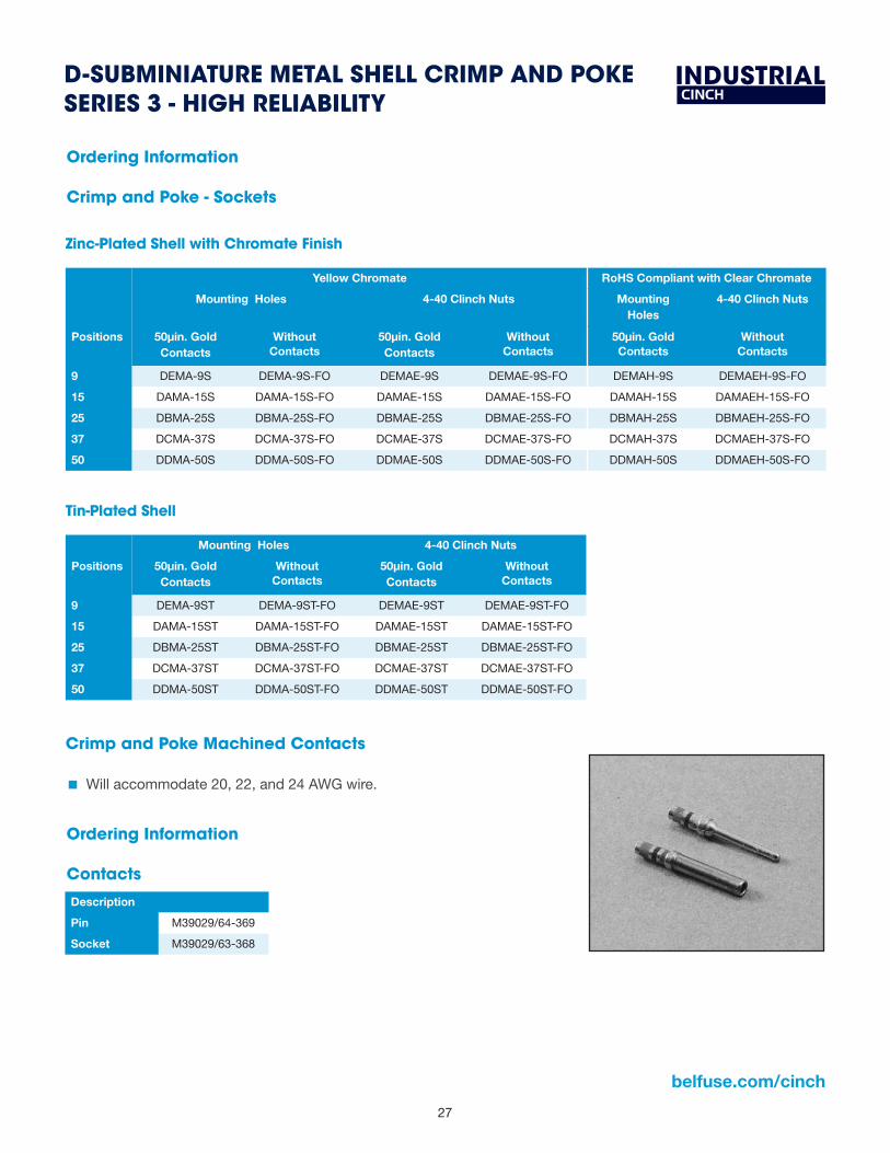
Crimp and Poke Machined Contacts
• Will accommodate 20, 22, and 24 AWG wire.
Ordering Information
Crimp and Poke - Sockets
Zinc-Plated Shell with Chromate Finish
Yellow Chromate RoHS Compliant with Clear Chromate
Mounting Holes 4-40 Clinch Nuts Mounting Holes
4-40 Clinch Nuts
Positions 50µin. Gold Contacts
Without Contacts
50µin. Gold Contacts
Without Contacts
50µin. Gold Contacts
Without Contacts
9 DEMA-9S DEMA-9S-FO DEMAE-9S DEMAE-9S-FO DEMAH-9S DEMAEH-9S-FO
15 DAMA-15S DAMA-15S-FO DAMAE-15S DAMAE-15S-FO DAMAH-15S DAMAEH-15S-FO
25 DBMA-25S DBMA-25S-FO DBMAE-25S DBMAE-25S-FO DBMAH-25S DBMAEH-25S-FO
37 DCMA-37S DCMA-37S-FO DCMAE-37S DCMAE-37S-FO DCMAH-37S DCMAEH-37S-FO
50 DDMA-50S DDMA-50S-FO DDMAE-50S DDMAE-50S-FO DDMAH-50S DDMAEH-50S-FO
Tin-Plated Shell
Mounting Holes 4-40 Clinch Nuts
Positions 50µin. Gold Contacts
Without Contacts
50µin. Gold Contacts
Without Contacts
9 DEMA-9ST DEMA-9ST-FO DEMAE-9ST DEMAE-9ST-FO
15 DAMA-15ST DAMA-15ST-FO DAMAE-15ST DAMAE-15ST-FO
25 DBMA-25ST DBMA-25ST-FO DBMAE-25ST DBMAE-25ST-FO
37 DCMA-37ST DCMA-37ST-FO DCMAE-37ST DCMAE-37ST-FO
50 DDMA-50ST DDMA-50ST-FO DDMAE-50ST DDMAE-50ST-FO
Crimp and Poke Machined Contacts
� Will accommodate 20, 22, and 24 AWG wire.
Ordering Information
Contacts
Description
Pin M39029/64-369
Socket M39029/63-368

28
INDUSTRIALD-SUBMINIATURE METAL SHELL MIL-C-24308 M24308 SERIES
Features
� Meets all MIL-C-24308 Class G specifications.
� Offered in Crimp and Poke and Solder Cup and PCB vertical and right-angle.
� Offered in 9, 15, 25, 37, and 50 position plugs and sockets except right-angle (9 to 37 positions).
� Monoblock green diallyl phthalate insulator for improved electrical performance.
� See pages 4-6 for standard dimensions, contact arrangements, and panel mounting specifications.
Materials
Insulator Material Glass-filled diallyl phthalate (green), per MIL-M-14, Type SDG-F
Connector Shell Steel with cadmium plating and yellow chromate finish
Contact Material Plug - Brass (machined), Socket - Phosphor bronze (machined)
Contact Plating 50μin gold over copper or nickel
4-40 Clinch Nut Steel with cadmium plating and yellow chromate finish
Dual Float Bushing Stainless Steel, passivated or non-magnetic brass
EnvironmentalOperating Temperature -65°C to +125°C
Shock 50G peak per MIL-STD-202, Method 213, Condition G
Vibration 12 cycles in three perpendicular directions @ 10-2000Hz, per MIL-STD-202, Method 204, Condition D
Moisture Resistance 90-95% relative humidity @ 40ºC for 96 hours per MIL-STD-202, Method 103
Electrical Withstanding Voltage Minimum 1250V RMS @ sea level
Current Rating 5 Amps
Contact Resistance 2.7 milliohms maximum
Insulation Resistance 5000 megohms maximum (initial); 1000 megohms (minimum) after environmental testing
MechanicalIndividual Contact Insertion and Separation Force
0.7 oz. minimum/12oz. maximum
Durability 500 mating cycles
4-74Call Toll Free: 1 (800) 323-9612
FEA
TURE
S
■■ Meets all MIL-C-24308 Class G specifications.■■ Offered in Crimp and Poke and Solder Cup and PCB vertical and right-angle.■■ Offered in 9, 15, 25, 37, and 50 position plugs and sockets except right-angle (9 to 37 positions).■■ Monoblock green diallyl phthalate insulator for improved electrical performance.■■ See pages 4-5 thru 4-10 for standard dimensions, contact arrangements, and panel
mounting specifications.
MA
TERI
ALS
Insulator Material: Glass-filled diallyl phthalate (green)per MIL-M-14, Type SDG-F
Connector Shell: Steel with cadmium plating and yellowchromate finish
Contact Material: Plug - Brass (machined), Socket - Phosphor bronze (machined)
Contact Plating: 50µin. gold over copper or nickelDual Float Bushing: Stainless steel, passivated or
non-magnetic brass
ENV
IRO
NM
ENTA
L Operating Temperature: -65°C to + 125°CShock: 50G peak per MIL-STD-202, Method 213, Condition GVibration: 12 cycles in three perpendicular directions @
10-2000Hz, per MIL-STD-202 Method 204, Condition D
Moisture Resistance: 90-95% relative humidity @ 40°C for 96 hours per MIL-STD-202, Method 103
ELEC
TRIC
AL
Withstanding Voltage: Minimum 1250V RMS @ sea level
Current Rating: 5 Amps
Contact Resistance: 2.7 milliohms maximum
Insulation Resistance: 5000 megohms maximum (initial);
1000 megohms (minimum) after
environmental testing
MEC
HA
NIC
AL
Individual Contact Insertion and Separation Force (minimum/maximum): 0.7 oz./12 oz.
Durability: 500 mating cycles
D-subminiature Metal ShellMIL-C-24308 M24308 Series

29
belfuse.com/cinch
INDUSTRIALD-SUBMINIATURE METAL SHELL MIL-C-24308 CRIMP AND POKE M24308 SERIES
� Available with .120 mounting holes, float bushings, or dual float bushings.
� Order with contacts included or separately.
� Order with contact Insertion/Extraction Tool included or order tool #CIET-20-HD separately. See page 51.
4-75 Call Toll Free: 1 (800) 323-9612
D-subminiature Metal ShellMIL-C-24308 Crimp and Poke M24308 Series
• Available with .120 mounting holes, float bushings, or dual float bushings.• Order with contacts included or separately.• Order with contact Insertion/Extraction Tool included or order tool #CIET-20-HD separately. See page 4-103.
Contacts Not Included. Insertion/Extraction Tool Not Included.Positions Mounting Holes Float Bushings Dual Float Bushings
9 M24308/4-259F M24308/4-324F M24308/4-457F15 M24308/4-260F M24308/4-325F M24308/4-458F25 M24308/4-261F M24308/4-326F M24308/4-459F37 M24308/4-262F M24308/4-327F M24308/4-460F50 M24308/4-263F M24308/4-328F M24308/4-461F
Steel Shell
Contacts Included. Insertion/Extraction Tool Not Included.Positions Mounting Holes Float Bushings Dual Float Bushings
9 M24308/4-1F M24308/4-302F M24308/4-435F15 M24308/4-2F M24308/4-303F M24308/4-436F25 M24308/4-3F M24308/4-304F M24308/4-437F37 M24308/4-4F M24308/4-305F M24308/4-438F50 M24308/4-5F M24308/4-306F M24308/4-439F
Contacts Included. Insertion/Extraction Tool Included.Positions Mounting Holes Float Bushings Dual Float Bushings
9 M24308/4-6F M24308/4-313F M24308/4-446F15 M24308/4-7F M24308/4-314F M24308/4-447F25 M24308/4-8F M24308/4-315F M24308/4-448F37 M24308/4-9F M24308/4-316F M24308/4-449F50 M24308/4-10F M24308/4-317F M24308/4-450F
Crimp and Poke Plugs
Ordering Information
Ordering Information
Crimp and Poke Plugs
Steel Shell
Contacts Included. Insertion/Extraction Tool Not Included.
Positions Mounting Holes Float Bushings Dual Float Bushings
9 M24308/4-1F M24308/4-302F M24308/4-435F
15 M24308/4-2F M24308/4-303F M24308/4-436F
25 M24308/4-3F M24308/4-304F M24308/4-437F
37 M24308/4-4F M24308/4-305F M24308/4-438F
50 M24308/4-5F M24308/4-306F M24308/4-439F
Contacts Included. Insertion/Extraction Tool Included.
Positions Mounting Holes Float Bushings Dual Float Bushings
9 M24308/4-6F M24308/4-313F M24308/4-446F
15 M24308/4-7F M24308/4-314F M24308/4-447F
25 M24308/4-8F M24308/4-315F M24308/4-448F
37 M24308/4-9F M24308/4-316F M24308/4-449F
50 M24308/4-10F M24308/4-317F M24308/4-450F
Contacts Included. Insertion/Extraction Tool Not Included.
Positions Mounting Holes Float Bushings Dual Float Bushings
9 M24308/4-259F M24308/4-324F M24308/4-457F
15 M24308/4-260F M24308/4-325F M24308/4-458F
25 M24308/4-261F M24308/4-326F M24308/4-459F
37 M24308/4-262F M24308/4-327F M24308/4-460F
50 M24308/4-263F M24308/4-328F M24308/4-461F

30
INDUSTRIALD-SUBMINIATURE METAL SHELL MIL-C-24308 CRIMP AND POKE M24308
Ordering Information
Crimp and Poke Sockets
Steel Shell
Contacts Included. Insertion/Extraction Tool Not Included.
Positions Mounting Holes Float Bushings Dual Float Bushings
9 M24308/2-1F M24308/2-23F M24308/2-342F
15 M24308/2-2F M24308/2-24F M24308/2-343F
25 M24308/2-3F M24308/2-25F M24308/2-344F
37 M24308/2-4F M24308/2-26F M24308/2-345F
50 M24308/2-5F M24308/2-27F M24308/2-346F
Contacts Included. Insertion/Extraction Tool Included.
Positions Mounting Holes Float Bushings Dual Float Bushings
9 M24308/2-6F M24308/2-34F M24308/2-353F
15 M24308/2-7F M24308/2-35F M24308/2-354F
25 M24308/2-8F M24308/2-36F M24308/2-355F
37 M24308/2-9F M24308/2-37F M24308/2-356F
50 M24308/2-10F M24308/2-38F M24308/2-357F
Contacts Included. Insertion/Extraction Tool Not Included.
Positions Mounting Holes Float Bushings Dual Float Bushings
9 M24308/2-281F M24308/2-292F M24308/2-482F
15 M24308/2-282F M24308/2-293F M24308/2-483F
25 M24308/2-283F M24308/2-294F M24308/2-484F
37 M24308/2-284F M24308/2-295F M24308/2-485F
50 M24308/2-285F M24308/2-296F M24308/2-486F

31
belfuse.com/cinch
INDUSTRIALD-SUBMINIATURE METAL SHELL MIL-C-24308 CRIMP AND POKE M24308 SERIES
Ordering Information
Tooling
� Contact Insertion/Extraction Tool: #CIET-20-HD (Military #M81969/39-01). See page 51.
� Wire termination hand tool: #M22520/2-01. See page 51.
� Positioner for machine contacts for hand tool #M22520/2-08 (locates contact in the correct position). See page 51.
Crimp and Poke Contacts
4-77
4
Call Toll Free: 1 (800) 323-9612
D-subminiature Metal ShellMIL-C-24308 Crimp and Poke M24308 Series
Ordering Information
Tooling
• Contact Insertion/Extraction Tool: #CIET-20-HD (Military #M81969/39-01). See page 4-103.• Wire termination hand tool: #M22520/2-01. See page 4-103.• Positioner for machine contacts for hand tool #M22520/2-08 (locates contact in the correct position). See page 4-103.
DescriptionPin M39029/64-369Socket M39029/63-368
Crimp and Poke Contacts
Ordering Information
• Will accommodate 20, 22, and 24 AWG wire.Ordering Information
� Will accommodate 20, 22, and 24 AWG wire.
Description
Pin M39029/64-369
Socket M39029/63-368

32
INDUSTRIALD-SUBMINIATURE METAL SHELL MIL-C-24308 SOLDER CUP M24308 SERIES
� Available with .120" mounting holes, float bushings, or dual float bushings.
� Will accommodate up to 20 AWG wire.
4-78
4
Call Toll Free: 1 (800) 323-9612
• Available with .120" mounting holes, float bushings, or dual float bushings.• Will accommodate up to 20 AWG wire.
D-subminiature Metal ShellMIL-C-24308 Solder Cup M24308 Series
Steel ShellPositions Mounting Holes Float Bushings Dual Float Bushings
9 M24308/3-1F M24308/3-12F M24308/3-17F15 M24308/3-2F M24308/3-13F M24308/3-18F25 M24308/3-3F M24308/3-14F M24308/3-19F37 M24308/3-4F M24308/3-15F M24308/3-20F50 M24308/3-5F M24308/3-16F M24308/3-21F
Brass Non-Magnetic ShellPositions Mounting Holes Float Bushings Dual Float Bushings
9 M24308/7-1F M24308/7-12F M24308/7-17F15 M24308/7-2F M24308/7-13F M24308/7-18F25 M24308/7-3F M24308/7-14F M24308/7-19F37 M24308/7-4F M24308/7-15F M24308/7-20F50 M24308/7-5F M24308/7-16F M24308/7-21F
Steel ShellPositions Mounting Holes Float Bushings Dual Float Bushings
9 M24308/1-1F M24308/1-12F M24308/1-23F15 M24308/1-2F M24308/1-13F M24308/1-24F25 M24308/1-3F M24308/1-14F M24308/1-25F37 M24308/1-4F M24308/1-15F M24308/1-26F50 M24308/1-5F M24308/1-16F M24308/1-27F
Brass Non-Magnetic ShellPositions Mounting Holes Float Bushings Dual Float Bushings
9 M24308/5-1F M24308/5-12F M24308/5-23F15 M24308/5-2F M24308/5-13F M24308/5-24F25 M24308/5-3F M24308/5-14F M24308/5-25F37 M24308/5-4F M24308/5-15F M24308/5-26F50 M24308/5-5F M24308/5-16F M24308/5-27F
Ordering Information
Solder Cup Plugs
Solder Cup Sockets
Ordering Information
Solder Cup Plugs
Steel Shell
Positions Mounting Holes Float Bushings Dual Float Bushings
9 M24308/3-1F M24308/2-12F M24308/2-17F
15 M24308/3-2F M24308/2-13F M24308/2-18F
25 M24308/3-3F M24308/2-14F M24308/2-19F
37 M24308/3-4F M24308/2-15F M24308/2-20F
50 M24308/3-5F M24308/2-16F M24308/2-21F
Brass Non-Magnetic Shell
Positions Mounting Holes Float Bushings Dual Float Bushings
9 M24308/7-1F M24308/7-12F M24308/7-17F
15 M24308/7-2F M24308/7-13F M24308/7-18F
25 M24308/7-3F M24308/7-14F M24308/7-19F
37 M24308/7-4F M24308/7-15F M24308/7-20F
50 M24308/7-5F M24308/7-16F M24308/7-21F
Solder Cup Sockets
Steel Shell
Positions Mounting Holes Float Bushings Dual Float Bushings
9 M24308/1-1F M24308/1-12F M24308/1-23F
15 M24308/1-2F M24308/1-13F M24308/1-24F
25 M24308/1-3F M24308/1-14F M24308/1-25F
37 M24308/1-4F M24308/1-15F M24308/1-26F
50 M24308/1-5F M24308/1-16F M24308/1-27F
Brass Non-Magnetic Shell
Positions Mounting Holes Float Bushings Dual Float Bushings
9 M24308/5-1F M24308/5-12F M24308/5-23F
15 M24308/5-2F M24308/5-13F M24308/5-24F
25 M24308/5-3F M24308/5-14F M24308/5-25F
37 M24308/5-4F M24308/5-15F M24308/5-26F
50 M24308/5-5F M24308/5-16F M24308/5-27F

33
belfuse.com/cinch
INDUSTRIALD-SUBMINIATURE METAL SHELL MIL-C-24308 PCB M24308 SERIES
Ordering Information
� .283" footprint requires minimal PCB space.
� Available with three contact tail lengths (.127" and .183") with .030" contact diameter.
� Offered with .120" mounting holes.
� Mounting bracket: Black nylon. Can be removed if necessary.
4-79
4
Call Toll Free: 1 (800) 323-9612
D-subminiature Metal ShellMIL-C-24308 PCBM24308 Series
Right-Angle Connector
• .283" footprint requires minimal PCB space.• Available with three contact tail lengths (.127", .158", and .183") with .030"
contact diameter.• Available with two contact tail lengths (.127" and .183") with .040"
contact diameter.• Offered with .120" mounting holes.• Mounting bracket: Black nylon. Can be removed if necessary.
0.396
0.340
0.283
Right-Angle PCB Plugs (Sockets not available)
Steel Shell.127 Tail Length .158 Tail Length .183 Tail Length .127 Tail Length .183 Tail Length
Positions .030 Contact Diameter .030 Contact Diameter .030 Contact Diameter .040 Contact Diameter .040 Contact Diameter9 M24308/24-25F M24308/24-31F M24308/24-49F M24308/24-37F M24308/24-55F
15 M24308/24-26F M24308/24-32F M24308/24-50F M24308/24-38F M24308/24-56F25 M24308/24-27F M24308/24-33F M24308/24-51F M24308/24-39F M24308/24-57F37 M24308/24-28F M24308/24-34F M24308/24-52F M24308/24-40F M24308/24-58F
Steel Shell.158 Tail Length .183 Tail Length .158 Tail Length .183 Tail Length
Positions .030 Contact Diameter .030 Contact Diameter .040 Contact Diameter .040 Contact Diameter 9 M24308/23-1F M24308/23-7F M24308/23-13F M24308/23-19F
15 M24308/23-2F M24308/23-8F M24308/23-14F M24308/23-20F25 M24308/23-3F M24308/23-9F M24308/23-15F M24308/23-21F37 M24308/23-4F M24308/23-10F M24308/23-16F M24308/23-22F50 M24308/23-5F M24308/23-11F M24308/23-17F M24308/23-23F
Steel Shell.158 Tail Length .183 Tail Length .158 Tail Length .183 Tail Length
Positions .030 Contact Diameter .030 Contact Diameter .040 Contact Diameter .040 Contact Diameter 9 M24308/24-1F M24308/24-7F M24308/24-13F M24308/24-19F
15 M24308/24-2F M24308/24-8F M24308/24-14F M24308/24-20F25 M24308/24-3F M24308/24-9F M24308/24-15F M24308/24-21F37 M24308/24-4F M24308/24-10F M24308/24-16F M24308/24-22F50 M24308/24-5F M24308/24-11F M24308/24-17F M24308/24-23F
Ordering Information
Right-Angle
Vertical
Vertical PCB Plugs
Vertical PCB Sockets
Vertical Connector
• Available with two contact tail lengths (.158" and .183") and two contactdiameters (.030" and .040").
• Offered with .120" mounting holes.
Ordering Information
See Chart
0.122 (2.84)
Ordering Information
Right-Angle PCB Plugs (Sockets not available)
Steel Shell
Positions .127 Tail Length .030 Contact Diameter
.183 Tail Length .030 Contact Diameter
9 M24308/24-25F M24308/24-49F
15 M24308/24-26F M24308/24-50F
25 M24308/24-27F M24308/24-51F
37 M24308/24-28F M24308/24-52F
Vertical Connector
� Available with two contact tail lengths (.158" and .183") with contact diameter .030".
� Offered with .120" mounting holes.
Ordering Information
Vertical PCB Plugs
Steel Shell
Positions .158 Tail Length .030 Contact Diameter
.183 Tail Length .030 Contact Diameter
9 M24308/24-1F M24308/24-7F
15 M24308/24-2F M24308/24-8F
25 M24308/24-3F M24308/24-9F
37 M24308/24-4F M24308/24-10F
50 M24308/24-5F M24308/24-11F
4-79
4
Call Toll Free: 1 (800) 323-9612
D-subminiature Metal ShellMIL-C-24308 PCBM24308 Series
Right-Angle Connector
• .283" footprint requires minimal PCB space.• Available with three contact tail lengths (.127", .158", and .183") with .030"
contact diameter.• Available with two contact tail lengths (.127" and .183") with .040"
contact diameter.• Offered with .120" mounting holes.• Mounting bracket: Black nylon. Can be removed if necessary.
0.396
0.340
0.283
Right-Angle PCB Plugs (Sockets not available)
Steel Shell.127 Tail Length .158 Tail Length .183 Tail Length .127 Tail Length .183 Tail Length
Positions .030 Contact Diameter .030 Contact Diameter .030 Contact Diameter .040 Contact Diameter .040 Contact Diameter9 M24308/24-25F M24308/24-31F M24308/24-49F M24308/24-37F M24308/24-55F
15 M24308/24-26F M24308/24-32F M24308/24-50F M24308/24-38F M24308/24-56F25 M24308/24-27F M24308/24-33F M24308/24-51F M24308/24-39F M24308/24-57F37 M24308/24-28F M24308/24-34F M24308/24-52F M24308/24-40F M24308/24-58F
Steel Shell.158 Tail Length .183 Tail Length .158 Tail Length .183 Tail Length
Positions .030 Contact Diameter .030 Contact Diameter .040 Contact Diameter .040 Contact Diameter 9 M24308/23-1F M24308/23-7F M24308/23-13F M24308/23-19F
15 M24308/23-2F M24308/23-8F M24308/23-14F M24308/23-20F25 M24308/23-3F M24308/23-9F M24308/23-15F M24308/23-21F37 M24308/23-4F M24308/23-10F M24308/23-16F M24308/23-22F50 M24308/23-5F M24308/23-11F M24308/23-17F M24308/23-23F
Steel Shell.158 Tail Length .183 Tail Length .158 Tail Length .183 Tail Length
Positions .030 Contact Diameter .030 Contact Diameter .040 Contact Diameter .040 Contact Diameter 9 M24308/24-1F M24308/24-7F M24308/24-13F M24308/24-19F
15 M24308/24-2F M24308/24-8F M24308/24-14F M24308/24-20F25 M24308/24-3F M24308/24-9F M24308/24-15F M24308/24-21F37 M24308/24-4F M24308/24-10F M24308/24-16F M24308/24-22F50 M24308/24-5F M24308/24-11F M24308/24-17F M24308/24-23F
Ordering Information
Right-Angle
Vertical
Vertical PCB Plugs
Vertical PCB Sockets
Vertical Connector
• Available with two contact tail lengths (.158" and .183") and two contactdiameters (.030" and .040").
• Offered with .120" mounting holes.
Ordering Information
See Chart
0.122 (2.84)
Positions .158 Tail Length .030 Contact Diameter
.183 Tail Length .030 Contact Diameter
9 M24308/23-1F M24308/23-7F
15 M24308/23-2F M24308/23-8F
25 M24308/23-3F M24308/23-9F
37 M24308/23-4F M24308/23-10F
50 M24308/23-5F M24308/23-11F
Vertical PCB Sockets
Steel Shell

34
INDUSTRIALD-SUBMINIATURE BACKSHELLS/JUNCTION SHELLS/HOODS ACCESSORIES
Features
Cinch backshells are offered in a variety of styles, each having a specific strength.
� Backshells have two-piece construction and are frequently used where appearance is a major factor. RFI/EMI shielding capability is also an option:• Plastic Backshells: No shielding.
• Metallized Plastic: Economical method of shielding.
• Diecast Backshells: Maximum shielding.
� Cinch SDH Series backshells utilize Cinch’s Latch-N-Lock™ system with quick release disconnect. Just squeeze the latch levers to release the connector. Also available with standard 4-40 mounting hardware.
� Junction Shells come in a variety of sizes and shapes including right-angle and low profile. They are generally of one-piece construction with an adjustable clamp, but there is no shielding.
� Hoods have an improved appearance versus junction shells but no shielding. They are all-plastic and come in right-angle or straight configurations.
� Hardware, in the form of adjustable grommets or strain relief clamps and 4-40 screws, is generally supplied with the product; however, a variety of optional hardware is also available in the accessories section of this catalog.
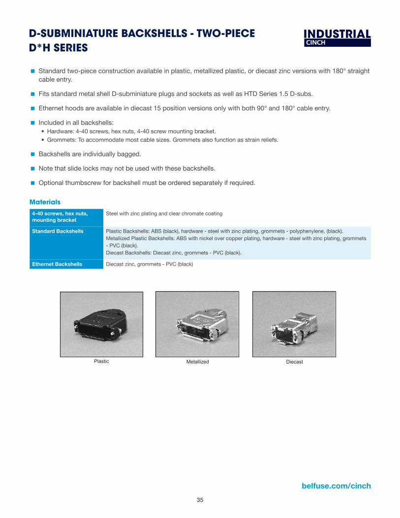
35
belfuse.com/cinch
INDUSTRIALD-SUBMINIATURE BACKSHELLS - TWO-PIECE D*H SERIES
� Standard two-piece construction available in plastic, metallized plastic, or diecast zinc versions with 180° straight cable entry.
� Fits standard metal shell D-subminiature plugs and sockets as well as HTD Series 1.5 D-subs.
� Ethernet hoods are available in diecast 15 position versions only with both 90° and 180° cable entry.
� Included in all backshells:• Hardware: 4-40 screws, hex nuts, 4-40 screw mounting bracket.• Grommets: To accommodate most cable sizes. Grommets also function as strain reliefs.
� Backshells are individually bagged.
� Note that slide locks may not be used with these backshells.
� Optional thumbscrew for backshell must be ordered separately if required.
4-82
4
Call Toll Free: 1 (800) 323-9612
• Standard two-piece construction available in plastic, metallized plastic, or diecast zinc versions with 180° straight cable entry.• Fits standard metal shell D-subminiature plugs and sockets as well as HTD Series 1.5 D-subs.• Ethernet hoods are available in diecast 15 position versions only with both 90° and 180° cable entry.• Included in all backshells:
- Hardware: 4-40 screws, hex nuts, 4-40 screw mounting bracket.- Grommets: To accommodate most cable sizes. Grommets also function as strain reliefs.
• Backshells are individually bagged.• Note that slide locks may not be used with these backshells.• Optional thumbscrew for backshell must be ordered separately if required.
Materials
• 4-40 screws, hex nuts, mounting bracket: Steel with zinc plating and clear chromate coating.• Standard Backshells:
- Plastic Backshells: ABS (black), hardware - steel with zinc plating, grommets - polyphenylene, (black).- Metallized Plastic Backshells: ABS with nickel over copper plating, hardware - steel with zinc plating,
grommets - PVC (black).- Diecast Backshells: Diecast zinc, grommets - PVC (black).
• Ethernet Backshells: Diecast zinc, grommets - PVC (black).
D-subminiature Backshells - Two-PieceD*H Series
Plastic
Ethernet Right-AngleEthernet Straight
DiecastMetallized
Materials
4-40 screws, hex nuts, mounting bracket
Steel with zinc plating and clear chromate coating
Standard Backshells Plastic Backshells: ABS (black), hardware - steel with zinc plating, grommets - polyphenylene, (black).Metallized Plastic Backshells: ABS with nickel over copper plating, hardware - steel with zinc plating, grommets - PVC (black).Diecast Backshells: Diecast zinc, grommets - PVC (black).
Ethernet Backshells Diecast zinc, grommets - PVC (black)

36
INDUSTRIALD-SUBMINIATURE BACKSHELLS - TWO-PIECE D*H SERIES
4-83
4
Call Toll Free: 1 (800) 323-9612
D-subminiature Backshells - Two-Piece D*H Series
Straight (180°) Standard Backshells
Plastic and Metallized Plastic Backshells
Dimensions
Shell A B C D E FSize in mm in mm in mm in mm in mm in mm
E 1.225 31.12 1.547 39.29 0.640 16.26 0.645 16.38 0.400 10.16 0.984 24.99A 1.540 39.12 1.516 38.51 0.640 16.26 0.645 16.38 0.400 10.16 1.312 33.32B 2.090 53.09 1.655 42.04 0.710 18.03 0.645 16.38 0.522 13.26 1.857 47.17C 2.730 69.34 1.830 46.48 0.906 23.01 0.645 16.38 0.725 18.42 2.500 63.50D 2.645 67.18 1.855 41.12 0.940 23.88 0.750 19.05 0.725 18.42 2.406 61.11
Straight (180º) Standard Backshells
Plastic and Metallized Plastic Backshells
A B C D E F
Shell Size in mm in mm in mm in mm in mm in mm
E 1.225 31.12 1.547 39.29 0.640 16.26 0.645 16.38 0.400 10.16 0.984 24.99
A 1.540 39.12 1.516 38.51 0.640 16.26 0.645 16.38 0.400 10.16 1.312 33.32
B 2.090 53.09 1.655 42.04 0.710 18.03 0.645 16.38 0.522 13.26 1.857 47.17
C 2.730 69.34 1.830 46.48 0.906 23.01 0.645 16.38 0.725 18.42 2.500 63.50
D 2.645 67.18 1.855 41.12 0.940 23.88 0.750 19.05 0.725 18.42 2.406 61.11
Dimensions

37
belfuse.com/cinch
INDUSTRIALD-SUBMINIATURE BACKSHELLS - TWO-PIECE D*H SERIES
4-84
4
Call Toll Free: 1 (800) 323-9612
D-subminiature Backshells - Two-PieceD*H Series
Dimensions
Shell A B C D E FSize in mm in mm in mm in mm in mm in mm
E 1.225 31.12 1.465 37.21 0.620 15.75 0.620 15.75 0.400 10.16 0.984 24.99A 1.540 39.12 1.600 40.64 0.620 15.75 0.620 15.75 0.400 10.16 1.312 33.32B 2.090 53.09 1.570 39.88 0.690 17.53 0.620 15.75 0.525 13.34 1.857 47.17C 2.730 69.34 1.810 45.97 0.862 21.89 0.620 15.75 0.725 18.42 2.500 63.50D 2.624 66.65 1.800 45.72 0.862 21.89 0.730 18.54 0.725 18.42 2.406 61.11
Ordering Information
D*H Two-Piece Backshells
Fits FitsShell Standard HTD 1.5 Cable Entry Cable Metallized Cable Diecast CableSize Density Density Style Plastic Dia. (in) Plastic Dia. (in) Metal Dia. (in)E 9 15 Straight (180°) DPH-E-001 .210-.320 DCH-E-001 .210-.350 DMH-E-001 .210-.320A 15 26 Straight (180°) DPH-A-001 .210-.320 DCH-A-001 .210-.350 DMH-A-001 .210-.320B 25 44 Straight (180°) DPH-B-001 .230-.450 DCH-B-001 .230-.450 DMH-B-001 .230-.450C 37 62 Straight (180°) DPH-C-001 .350-.650 DCH-C-001 .350-.640 DMH-C-001 .350-.650D 50 N/A Straight (180°) DPH-D-001 .350-.650 DCH-D-001 .350-.640 DMH-D-001 .350-.640
EMI/RFI Shielded Diecast BackshellsEMI/RFI Shielded Diecast Backshells
A B C D E F
Shell Size in mm in mm in mm in mm in mm in mm
E 1.225 31.12 1.465 37.21 0.620 15.75 0.620 15.75 0.400 10.16 0.984 24.99
A 1.540 39.12 1.600 40.64 0.620 15.75 0.620 15.75 0.400 10.16 1.312 33.32
B 2.090 53.09 1.570 39.88 0.690 17.53 0.620 15.75 0.525 13.34 1.857 47.17
C 2.730 69.34 1.810 45.97 0.862 21.89 0.620 15.75 0.725 18.42 2.500 63.50
D 2.624 66.65 1.800 45.72 0.862 21.89 0.730 18.54 0.725 18.42 2.406 61.11
Dimensions
Shell Size Fits Standard Density
Cable Entry Style
RoHS Compliant
Plastic
Cable Dia. (in)
RoHS Compliant Metallized
Plastic
Cable Dia. (in)
Diecast Metal
Cable Dia. (in)
E 9 Straight (180º) DPH-E-003 .210-.320 DCH-E-003 .210-.350 DMH-E-003 .210-.320
A 15 Straight (180º) .210-.320 DCH-A-003 .210-.350 DMH-A-003 .210-.320
B 25 Straight (180º) DPH-B-003 .230-.450 DCH-B-003 .230-.450 .230-.450
C 37 Straight (180º) .350-.650 DCH-C-003 .350-.640 .350-.650
Ordering Information
D*H Two-Piece Backshells
9 and 15 Position
25 Position
37 and 50 Position

38
INDUSTRIALD-SUBMINIATURE BACKSHELLS - SUPER D SDH SERIES
Features
� The Cinch Super D Interconnection System is a simple, fast, economical, and reliable way for mating connectors from cable to cable or cable to panel.
� Snap-on Super D plastic hoods captivate connectors providing positive, self-latching, audible mating with reliable retention and Latch-N-Lock quick release disconnect.
� Snap-on Super-D plastic hoods are also available with filler ends to utilize 4-40 mounting hardware.
� Black SDH backshells accommodate any standard metal shell IDC, solder cup, or crimp and poke D-subminiature connector.
� Gray SDH backshells accommodate the Cinch All-Plastic IDC T-Series connector on page 15.
� Each Super-D plastic hood includes a stay band to strain relief the cable wire. Stay band tool SD-MSBT is required.
Materials
Hood Modified phenylene oxide - black for metal shell connectors or gray for all-plastic IDC connectors
Latch Block Diecast zinc
Screws for Latching Blocks Steel with nickel plating
Stay Band Steel with zinc plating and clear chromate finish
4-86Call Toll Free: 1 (800) 323-9612
FEA
TURE
S
■ The Cinch Super D Interconnection System is a simple, fast, economical, and reliable way for mating connectors from cable to cable or cable to panel.
■ Snap-on Super D plastic hoods captivate connectors providing positive, self-latching, audible mating with reliable retention and Latch-N-Lock quick release disconnect.
■ Snap-on Super-D plastic hoods are also available with filler ends to utilize 4-40 mounting hardware.
■ Super D hoods are available:- Straight (180°) or Right-Angle (90°) cable entry.- Sizes: 9, 15, 25, and 37.- Sizes 15, 25, and 37 are available in standard or large cable openings.
■ Black SDH backshells accommodate any standard metal shell IDC, solder cup, or crimp and poke D-subminiature connector.
■ Gray SDH backshells accommodate the Cinch All-Plastic IDC T-Series connector on pages 4-38 thru 4-39.
■ Each Super-D plastic hood includes a stay band to strain relief the cable wire. Stay band tool SD-MSBT is required. Extra stay bands are available on page 4-90.
MA
TERI
ALS
Hood: Modified phenylene oxide - black for metal shell connectors or gray for all-plasticIDC connectors
Latch Block: Diecast zincScrews for Latching Blocks: Steel with nickel platingStay Band: Steel with zinc plating and clear chromate finish
D-subminiature Backshells - Super DSDH Series

39
belfuse.com/cinch
INDUSTRIALD-SUBMINIATURE BACKSHELLS - FOR USE WITH METAL SELL CONNECTORS SDH SERIESStraight (180º) Cable Entry Black Backshells for Metal Shell Connectors
4-87
4
Call Toll Free: 1 (800) 323-9612
D-subminiatureBackshells - For use with Metal Shell ConnectorsSDH Series
Straight (180°) Cable Entry Black Backshells for Metal Shell Connectors
Right-Angle (90°) Cable Entry Black Backshells for Metal Shell Connectors
Dimensions
A + .020" (.58mm) B +.020" (.58mm) C +.020" (.58mm) D +.020" (.58mm) E+.020" (.58mm)Positions in mm in mm in mm in mm in mm
9 1.47 37.34 .31 7.87 - - 1.94 49.21 1.25 31.7515 1.80 45.72 .31 7.87 .41 10.41 2.25 57.15 1.34 34.1325 2.35 59.69 .33 8.40 .47 11.94 2.94 74.61 1.50 38.1037 2.99 75.95 .37 9.40 .50 12.70 3.59 91.28 1.53 38.89
Adapter Hood with Filler Ends Adapter Hood with Latches
Right-Angle Adapter Hood
Right-Angle (90º) Cable Entry Black Backshells for Metal Shell Connectors
A ± .020" (.58mm) B ± .020" (.58mm) C ± .020" (.58mm) D ± .020" (.58mm) E ± .020" (.58mm)
Positions in mm in mm in mm in mm in mm
9 1.47 37.34 .31 7.87 - - 1.94 49.21 1.25 31.75
15 1.80 45.72 .31 7.87 .41 10.41 2.25 57.15 1.34 34.13
25 2.35 59.69 .33 8.40 .47 11.94 2.94 74.61 1.50 38.10
37 2.99 75.95 .37 9.40 .50 12.70 3.59 91.28 1.53 38.89
Dimensions
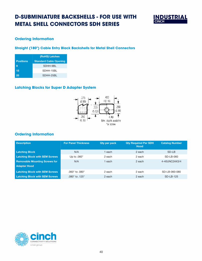
40
INDUSTRIALD-SUBMINIATURE BACKSHELLS - FOR USE WITH METAL SHELL CONNECTORS SDH SERIES
Ordering Information
Straight (180º) Cable Entry Black Backshells for Metal Shell Connectors
(RoHS) Latches
Positions Standard Cable Opening
9 SDHH-9BL
15 SDHH-15BL
25 SDHH-25BL
Latching Blocks for Super D Adapter System
4-88
4
Call Toll Free: 1 (800) 323-9612
D-subminiatureBackshells - For use with Metal Shell ConnectorsSDH Series
Straight (180°) Cable Entry Black Backshells for Metal Shell Connectors
Latching Blocks for Super D Adapter System
Latches Filler Ends Filler Ends w/4-40 ScrewsStandard Large Standard Large Standard Large
Positions Cable Opening Cable Opening Cable Opening Cable Opening Cable Opening Cable Opening9 SDH-9BL N/A SDH-9BF N/A SDH-9BFCS N/A
15 SDH-15BL SDH-15BLL SDH-15BF SDH-15BFL SDH-15BFCS SDH-15BFLCS25 SDH-25BL SDH-25BLL SDH-25BF SDH-25BFL SDH-25BFCS SDH-25BFLCS37 SDH-37BL SDH-37BLL SDH-37BF SDH-37BFL SDH-37BFCS SDH-37BFLCS
Ordering Information
Qty RequiredDescription For Panel Thickness Qty per pack Per SDH Hood Catalog NumberLatching Block N/A 1 each 2 each SD-LBLatching Block with SEM Screws Up to .060" 2 each 2 each SD-LB-060Removable Mounting Screws for Adapter Hood N/A 1 each 2 each 4-40UNC2AX3/4Latching Block with SEM Screws .060" to .080" 2 each 2 each SD-LB-060-080Latching Block with SEM Screws .080” to .125" 2 each 2 each SD-LB-125
Ordering Information
Ordering Information
LatchesStandard Cable Large Cable
Positions Opening Opening9 SDH-9RBL N/A
15 SDH-15RBL SDH-15RBLL25 SDH-25RBL SDH-25RBLL37 SDH-37RBL SDH-37RBLL
Right-Angle (90°) Cable Entry Black Backshells for Metal Shell Connectors
Ordering Information
Description For Panel Thickness Qty per pack Qty Required Per SDH Hood
Catalog Number
Latching Block N/A 1 each 2 each SD-LB
Latching Block with SEM Screws Up to .060" 2 each 2 each SD-LB-060
Removable Mounting Screws for
Adapter Hood
N/A 1 each 2 each 4-40UNC2AX3/4
Latching Block with SEM Screws .060" to .080" 2 each 2 each SD-LB-060-080
Latching Block with SEM Screws .080" to .125" 2 each 2 each SD-LB-125

41
belfuse.com/cinch
INDUSTRIALD-SUBMINIATURE BACKSHELLS - GRAY WITH ALL-PLASTIC CONNECTORS SDH SERIES
� Fits only T Series All-Plastic IDC connector on page 14.
Straight (180°) Cable Entry Gray Backshells for All-Plastic Connectors
4-89
4
Call Toll Free: 1 (800) 323-9612
D-subminiatureBackshells - Gray with All-Plastic ConnectorsSDH Series
Straight (180°) Cable Entry Gray Backshells for All-Plastic Connectors
Dimensions
A +.020" (.58mm) B +.020" (.58mm) C +.020" (.58mm)Positions in mm in mm in mm
9 1.47 37.34 .31 7.87 --- ---15 1.80 45.72 .31 7.87 .41 10.4125 2.35 59.69 .33 8.40 .47 11.9437 2.99 75.95 .37 9.40 .50 12.70
• Fits only T Series All-Plastic IDC connector on pages 4-38 thru 4-39.
Ordering Information
Straight (180°) Cable Entry Gray Backshells for All-Plastic Connectors
Latches Filler Ends Filler Ends w/4-40 ScrewsStandard Large Standard Large Standard Large
Positions Cable Opening Cable Opening Cable Opening Cable Opening Cable Opening Cable Opening9 SDH-9GL N/A SDH-9GF N/A SDH-9GFCS N/A
15 SDH-15GL SDH-15GLL SDH-15GF SDH-15GFL SDH-15GFCS SDH-15GFLCS25 SDH-25GL SDH-25GLL SDH-25GF SDH-25GFL SDH-25GFCS SDH-25GFLCS37 SDH-37GL SDH-37GLL SDH-37GF SDH-37GFL SDH-37GFCS SDH-37GFLCS
A ± .020" (.58mm) B ± .020" (.58mm) C ± .020" (.58mm)
Positions in mm in mm in mm
9 1.47 37.34 .31 7.87 - -
15 1.80 45.72 .31 7.87 .41 10.41
25 2.35 59.69 .33 8.40 .47 11.94
37 2.99 75.95 .37 9.40 .50 12.70
Dimensions
Ordering Information
Straight (180º) Cable Entry Gray Backshells for All-Plastic Connectors
Latches Filler Ends Filler Ends w/4-40 Screws
Positions Standard Cable Opening Standard Cable Opening Large Cable Opening
9 SDH-9GL SDH-9GF N/A
15 SDH-15GL SDH-15GF SDH-15GFLCS
25 SDH-25GL SDH-25GF SDH-25GFLCS
37 SDH-37GL SDH-37GF SDH-37GFLCS

42
INDUSTRIALD-SUBMINIATURE BACKSHELLS - GRAY USE WITH ALL-PLASTIC CONNECTORS SDH SERIESRight-Angle (90°) Cable Entry Gray Backshells for All-Plastic Connectors
� Fits only IDC connector on pages 15.
4-90
4
Call Toll Free: 1 (800) 323-9612
D-subminiatureBackshells - Gray use with All-Plastic ConnectorsSDH Series
Ordering Information
LatchesStandard Cable Large Cable
Positions Opening Opening9 SDH-9RGL N/A
15 SDH-15RGL SDH-15RGLL25 SDH-25RGL SDH-25RGLL37 SDH-37RGL SDH-37RGLL
Ordering Information
Accessories for Gray Backshells
Optional AdditionalPositions Strain Reliefs* Stay Bands**
9 SD-WC9 SD-9-15-SB15 SD-WC15 SD-9-15-SB25 SD-WC25 SD-25-37-SB37 SD-WC37 SD-25-37-SB
Screw for screwlocking connector assembly - (2 each required): 4-40UNC2AX3/4.
* Two each required per backshell.** Stay band tool #SD-MSBT required. See page 4-100..
Right-Angle (90°) Cable Entry Gray Backshells for All-Plastic Connectors• Fits only IDC connectors on pages 4-38 thru 4-39.
Dimensions
A +.020" (.58mm) B +.020" (.58mm) C +.020" (.58mm) D +.020" (.58mm)Positions in mm in mm in mm in mm
9 1.94 49.21 .31 7.87 -- --- 1.25 31.7515 2.25 57.15 .31 7.87 .41 10.41 1.34 34.1325 2.94 74.61 .33 8.40 .47 11.94 1.50 38.1037 3.59 91.28 .37 9.40 .50 12.70 1.53 38.89
See page 4-85 for latch block drawing.
Right-Angle (90°) Cable Entry Gray Backshells for All-Plastic Connectors
A ± .020" (.58mm) B ± .020" (.58mm) C ± .020" (.58mm) D ± .020" (.58mm)
Positions in mm in mm in mm in mm
9 1.94 49.21 .31 7.87 - - 1.25 31.75
15 2.25 57.15 .31 7.87 .41 10.41 1.34 34.13
25 2.94 74.61 .33 8.40 .47 11.94 1.50 38.10
37 3.59 91.28 .37 9.40 .50 12.70 1.53 38.89
Dimensions
Ordering Information
Right Angle (90º) Cable Entry Gray Backshells for All-Plastic Connectors
Latches
Positions Standard Cable Opening
9 SDH-9RGL
15 SDH-15RGL
25 SDH-25RGL
37 SDH-37RGL
Ordering Information
Accessories for Gray Backshells
Positions Optional Strain Reliefs* Additional Stay Bands**
9 SD-WC9 SD-9-15-SB
15 SD-WC15 SD-9-15-SB
25 SD-WC25 SD-25-37-SB
37 SD-WC37 SD-25-37-SB
* Two each required per backshell.
** Stay band tool #SD-MSBT required.
Screw for screwlocking connector assembly -(2 each required): 4-40UNC2ZX3/4.
4-90
4
Call Toll Free: 1 (800) 323-9612
D-subminiatureBackshells - Gray use with All-Plastic ConnectorsSDH Series
Ordering Information
LatchesStandard Cable Large Cable
Positions Opening Opening9 SDH-9RGL N/A
15 SDH-15RGL SDH-15RGLL25 SDH-25RGL SDH-25RGLL37 SDH-37RGL SDH-37RGLL
Ordering Information
Accessories for Gray Backshells
Optional AdditionalPositions Strain Reliefs* Stay Bands**
9 SD-WC9 SD-9-15-SB15 SD-WC15 SD-9-15-SB25 SD-WC25 SD-25-37-SB37 SD-WC37 SD-25-37-SB
Screw for screwlocking connector assembly - (2 each required): 4-40UNC2AX3/4.
* Two each required per backshell.** Stay band tool #SD-MSBT required. See page 4-100..
Right-Angle (90°) Cable Entry Gray Backshells for All-Plastic Connectors• Fits only IDC connectors on pages 4-38 thru 4-39.
Dimensions
A +.020" (.58mm) B +.020" (.58mm) C +.020" (.58mm) D +.020" (.58mm)Positions in mm in mm in mm in mm
9 1.94 49.21 .31 7.87 -- --- 1.25 31.7515 2.25 57.15 .31 7.87 .41 10.41 1.34 34.1325 2.94 74.61 .33 8.40 .47 11.94 1.50 38.1037 3.59 91.28 .37 9.40 .50 12.70 1.53 38.89
See page 4-85 for latch block drawing.
Right-Angle (90°) Cable Entry Gray Backshells for All-Plastic Connectors

43
belfuse.com/cinch
INDUSTRIALD-SUBMINIATURE JUNCTION SHELLS
Materials
Shell Material Zinc-plated low carbon steel with yellow chromate finish or RoHS clear chromate finish
Clamp Zinc-plated steel with yellow chromate finish
Screw Zinc-plated steel with yellow chromate finish
Stop Nut Zinc-plated brass with yellow chromate finish
4-92Call Toll Free: 1 (800) 323-9612
MA
TERI
ALS
■ Shell Material: Zinc-plated low carbon steel with yellow chromate finish.
■ Clamp: Zinc-plated steel with yellow chromate finish.
■ Screw: Zinc-plated steel with yellow chromate finish.
■ Stop Nut: Zinc-plated brass with yellow chromate finish.
Straight Clamp
D-subminiature Junction Shells
Round Clamp
Right-Angle Clamp
Shell A B C E F GSize Positions in mm in mm in mm in mm in mm in mm
A 15 1.531 38.89 .500 12.70 1.312 33.32 .296 7.52 .312 7.92 .640 16.26B 25 2.078 52.78 .500 12.70 1.852 47.04 .296 7.52 .796 20.22 .640 16.26C 37 2.718 69.04 .500 12.70 2.500 63.50 .296 7.52 .687 17.45 .640 16.26D 50 2.625 66.68 .609 15.47 2.406 61.11 .390 9.91 .687 17.45 .703 17.86
Shell A B C D E F GSize Positions in mm in mm in mm in mm in mm in mm in mm
A 15 1.531 38.89 .500 12.70 1.312 33.32 .406 10.31 .984 23.72 .125 3.18 1.031 26.19B 25 2.078 52.78 .500 12.70 1.852 47.04 .593 15.06 1.515 38.48 .187 4.75 1.062 26.97
Shell A B C E F G HSize Positions in mm in mm in mm in mm in mm in mm in mm
E 9 1.203 30.56 0.718 18.24 .984 24.99 .437 11.10 .437 11.10 .468 11.89 .281 7.14A 15 1.531 38.89 0.718 18.24 1.312 33.32 .437 11.10 .437 11.10 .468 11.89 .281 7.14B 25 2.078 52.78 0.968 24.59 1.852 47.04 .437 11.10 .625 15.88 .468 11.89 .281 7.14C 37 2.718 69.04 1.187 30.15 2.500 63.50 .437 11.10 .812 20.62 .468 11.89 .281 7.14D 50 2.625 66.68 1.250 31.75 2.406 61.11 .562 14.27 .906 23.01 .531 13.49 .343 8.71
E
Round Clamp
A B C D E F G
Shell Size Positions in mm in mm in mm in mm in mm in mm in mm
A 15 1.531 38.89 .500 12.70 1.312 33.32 .406 10.31 .984 23.72 .125 3.18 1.031 26.19
B 25 2.078 52.78 .500 12.70 1.852 47.04 .593 15.06 1.515 38.48 .187 4.75 1.062 26.97
4-92Call Toll Free: 1 (800) 323-9612
MA
TERI
ALS
■ Shell Material: Zinc-plated low carbon steel with yellow chromate finish.
■ Clamp: Zinc-plated steel with yellow chromate finish.
■ Screw: Zinc-plated steel with yellow chromate finish.
■ Stop Nut: Zinc-plated brass with yellow chromate finish.
Straight Clamp
D-subminiature Junction Shells
Round Clamp
Right-Angle Clamp
Shell A B C E F GSize Positions in mm in mm in mm in mm in mm in mm
A 15 1.531 38.89 .500 12.70 1.312 33.32 .296 7.52 .312 7.92 .640 16.26B 25 2.078 52.78 .500 12.70 1.852 47.04 .296 7.52 .796 20.22 .640 16.26C 37 2.718 69.04 .500 12.70 2.500 63.50 .296 7.52 .687 17.45 .640 16.26D 50 2.625 66.68 .609 15.47 2.406 61.11 .390 9.91 .687 17.45 .703 17.86
Shell A B C D E F GSize Positions in mm in mm in mm in mm in mm in mm in mm
A 15 1.531 38.89 .500 12.70 1.312 33.32 .406 10.31 .984 23.72 .125 3.18 1.031 26.19B 25 2.078 52.78 .500 12.70 1.852 47.04 .593 15.06 1.515 38.48 .187 4.75 1.062 26.97
Shell A B C E F G HSize Positions in mm in mm in mm in mm in mm in mm in mm
E 9 1.203 30.56 0.718 18.24 .984 24.99 .437 11.10 .437 11.10 .468 11.89 .281 7.14A 15 1.531 38.89 0.718 18.24 1.312 33.32 .437 11.10 .437 11.10 .468 11.89 .281 7.14B 25 2.078 52.78 0.968 24.59 1.852 47.04 .437 11.10 .625 15.88 .468 11.89 .281 7.14C 37 2.718 69.04 1.187 30.15 2.500 63.50 .437 11.10 .812 20.62 .468 11.89 .281 7.14D 50 2.625 66.68 1.250 31.75 2.406 61.11 .562 14.27 .906 23.01 .531 13.49 .343 8.71
E
Right-Angle Clamp
A B C E F G H
Shell Size Positions in mm in mm in mm in mm in mm in mm in mm
E 9 1.203 30.56 0.718 18.24 .984 24.99 .437 11.10 .437 11.10 .468 11.89 .281 7.14
A 15 1.531 38.89 0.718 18.24 1.312 33.32 .437 11.10 .437 11.10 .468 11.89 .281 7.14
B 25 2.078 52.78 0.968 24.59 1.852 47.04 .437 11.10 .625 15.88 .468 11.89 .281 7.14
C 37 2.718 69.04 1.187 30.15 2.500 63.50 .437 11.10 .812 20.62 .468 11.89 .281 7.14
D 50 2.625 66.68 1.250 31.75 2.406 61.11 .562 14.27 .906 23.01 .531 13.49 .343 8.71

44
INDUSTRIALD-SUBMINIATURE JUNCTION SHELLS
Deep Straight Clamp
4-93 Call Toll Free: 1 (800) 323-9612
Junction Shells - Metal
FitsShell Standard Straight Round Right-Angle Deep Straight SwitchingSize Density Clamp Clamp Clamp Clamp Shell
E 9 N/A N/A DE-19977-5 DE-24657 N/AA 15 DA-19678-1 DA-20961 DA-19977-1 DA-24658 DA-19678-6B 25 DB-19678-2 DB-20962 DB-19977-2 DB-24659 DB-19678-7C 37 DC-19678-3 N/A DC-19977-3 DC-24660 DC-19678-8D 50 DD-19678-4 N/A DD-19977-4 DD-24661 DD-19678-9
D-subminiature Junction Shells
Deep Straight Clamp
Switching Shell
Shell A B C D E F G HSize Positions in mm in mm in mm in mm in mm in mm in mm in mm
E 9 1.203 30.56 .484 12.29 0.984 24.99 .578 14.68 .375 9.53 .375 9.53 .750 19.05 1.219 30.96A 15 1.531 38.89 .484 12.29 1.312 33.32 .578 14.68 .713 18.11 .312 7.92 .750 19.05 1.250 31.75B 25 2.078 52.78 .484 12.29 1.852 47.04 .578 14.68 1.000 25.40 .312 7.92 1.000 25.40 1.531 38.89C 37 2.718 69.04 .484 12.29 2.500 63.50 .578 14.68 1.375 34.93 .312 7.92 1.000 25.40 1.531 38.89D 50 2.625 66.68 .593 15.06 2.406 61.11 .687 17.45 1.406 35.71 .406 10.31 1.125 28.58 1.656 42.06
Shell A B CSize Positions in mm in mm in mm
A 15 1.531 38.89 .500 12.70 1.312 33.32B 25 2.078 52.78 .500 12.70 1.852 47.04C 37 2.718 69.04 .500 12.70 2.500 63.50D 50 2.625 66.68 .609 15.47 2.406 61.11
Ordering Information
F ± .015
Shell Size
A B C D E F G H
Positions in mm in mm in mm in mm in mm in mm in mm in mm
E 9 1.203 30.56 .484 12.29 .984 24.99 .578 14.68 .375 9.53 .375 9.53 .750 19.05 1.219 30.96
A 15 1.531 38.89 .484 12.29 1.312 33.32 .578 14.68 .713 18.11 .312 7.92 .750 19.05 1.250 31.75
B 25 2.078 52.78 .484 12.29 1.852 47.04 .578 14.68 1.000 25.40 .312 7.92 1.000 25.40 1.531 38.89
C 37 2.718 69.04 .484 12.29 2.500 63.50 .578 14.68 1.375 34.93 .312 7.92 1.000 25.40 1.531 38.89
D 50 2.625 66.68 .593 15.06 2.406 61.11 .687 17.45 1.406 35.71 .406 10.31 1.125 28.58 1.656 42.06
Switching Shell
4-93 Call Toll Free: 1 (800) 323-9612
Junction Shells - Metal
FitsShell Standard Straight Round Right-Angle Deep Straight SwitchingSize Density Clamp Clamp Clamp Clamp Shell
E 9 N/A N/A DE-19977-5 DE-24657 N/AA 15 DA-19678-1 DA-20961 DA-19977-1 DA-24658 DA-19678-6B 25 DB-19678-2 DB-20962 DB-19977-2 DB-24659 DB-19678-7C 37 DC-19678-3 N/A DC-19977-3 DC-24660 DC-19678-8D 50 DD-19678-4 N/A DD-19977-4 DD-24661 DD-19678-9
D-subminiature Junction Shells
Deep Straight Clamp
Switching Shell
Shell A B C D E F G HSize Positions in mm in mm in mm in mm in mm in mm in mm in mm
E 9 1.203 30.56 .484 12.29 0.984 24.99 .578 14.68 .375 9.53 .375 9.53 .750 19.05 1.219 30.96A 15 1.531 38.89 .484 12.29 1.312 33.32 .578 14.68 .713 18.11 .312 7.92 .750 19.05 1.250 31.75B 25 2.078 52.78 .484 12.29 1.852 47.04 .578 14.68 1.000 25.40 .312 7.92 1.000 25.40 1.531 38.89C 37 2.718 69.04 .484 12.29 2.500 63.50 .578 14.68 1.375 34.93 .312 7.92 1.000 25.40 1.531 38.89D 50 2.625 66.68 .593 15.06 2.406 61.11 .687 17.45 1.406 35.71 .406 10.31 1.125 28.58 1.656 42.06
Shell A B CSize Positions in mm in mm in mm
A 15 1.531 38.89 .500 12.70 1.312 33.32B 25 2.078 52.78 .500 12.70 1.852 47.04C 37 2.718 69.04 .500 12.70 2.500 63.50D 50 2.625 66.68 .609 15.47 2.406 61.11
Ordering Information
F ± .015
A B C
Shell Size Positions in mm in mm in mm
A 15 1.531 38.89 .500 12.70 1.312 33.32
B 25 2.078 52.78 .500 12.70 1.852 47.04
C 37 2.718 69.04 .500 12.70 2.500 63.50
D 50 2.625 66.68 .609 15.47 2.406 61.11
Ordering Information
Junction Shells - Metal
Yellow Chromate RoHS Clear Chromate
Shell Size Fits Standard Density
Round Clamp Right-Angle Clamp
Deep Straight Clamp
Switching Shell Right-Angle Clamp
Deep Straight Clamp
E 9 N/A DE-19977-5 DE-24657 N/A DE-19977-30 DE-24657-30
A 15 DA-24658 DA-19678-6 DA-19977-31 DA-24658-31
B 25 DB-20962 DB-19977-2 DB-24659 DB-19678-7 DB-19977-32 DB-24659-32
C 37 N/A DC-24660 DC-24660-33

45
belfuse.com/cinch
INDUSTRIALD-SUBMINIATURE PLASTIC HOODS
Phenolic Hood
Shell Material: Phenolic (black).#4-40 Screws: Steel with nickel plating.
Ordering Information
Plastic HoodsShell Standard Phenolic Straight RightSize Density Hood Hood Angle
E 9 N/A DE-51218-1 N/AA 15 DA-51225-1 DA-51210-1 DA-51211-1B 25 DB-51226-1A DB-51212-1 DB-51213-1C 37 N/A N/A N/AD 50 N/A N/A N/A
All-Plastic Straight (180°) Hood
Shell Material: Nylon (gray).#4-40 Screws: Steel with nickel plating.
All-Plastic Right-Angle (90°) Hood
Shell Material: Nylon (gray).#4-40 Screws: Steel with nickel plating.
D-subminiature Plastic Hoods
Shell A B C D E F GSize Positions in mm in mm in mm in mm in mm in mm in mm
E 9 1.218 30.94 1.000 25.40 .984 23.72 .500 12.70 .562 14.27 .281 7.14 .218 7.14A 15 1.546 38.27 1.000 25.40 1.312 33.32 .500 12.70 .562 14.27 .360 9.14 .360 9.14B 25 2.093 53.16 1.250 31.75 1.852 47.04 .500 12.70 .562 14.27 .493 12.52 .360 9.14
Shell A B C D ESize Positions in mm in mm in mm in mm in mm
A 15 1.297 32.94 1.219 30.96 .266 6.76 1.312 33.32 1.641 41.68B 25 1.406 35.71 1.797 45.64 .328 8.33 1.852 47.04 2.203 55.96
Shell A B C D E FSize Positions in mm in mm in mm in mm in mm in mm
A 15 1.822 46.28 1.000 25.40 1.312 33.32 .500 12.70 .562 14.28 .360 9.14B 25 2.368 60.15 1.250 31.75 1.852 47.04 .500 12.70 .562 14.28 .360 9.14
Connector Not Included
Connector Not Included
4-94Call Toll Free: 1 (800) 323-9612
All-Plastic Straight (180º) Hood
Shell Material: Nylon (gray).
#4-40 Screws: Steel with nickel plating.
A B C D E F G
Shell Size Positions in mm in mm in mm in mm in mm in mm in mm
E 9 1.218 30.94 1.000 25.40 .984 23.72 .500 12.70 .562 14.27 .281 7.14 .218 7.14
A 15 1.546 38.27 1.000 25.40 1.312 33.32 .500 12.70 .562 14.27 .360 9.14 .360 9.14
B 25 2.093 53.16 1.250 31.75 1.852 47.04 .500 12.70 .562 14.27 .93 12.52 .360 9.14
Ordering Information
Plastic Hoods
Shell Size Standard Density
Straight
Hood
E 9 DE-51218-1
A 15 DA-51210-1
B 25 DB-51212-1

46
INDUSTRIAL
4-96Call Toll Free: 1 (800) 323-9612
Dust Caps
• For use with all Cinch D-subminiature connectors.• Used to protect connector contacts when connector is not mated.• Made of polyethylene (black).
Guide Pin Plates
• Aligns connectors before actual mating. Generally used in blind mate applications.• Male or female guide plates will accommodate Cinch male or female connectors.• Plate: Cold-rolled steel with cadmium plating and yellow chromate finish.• Guide pin (male): Stainless steel, passivated.• Screws, rivets (male plate), washers (male plate): Steel with cadmium plating and yellow chromate finish.
Ordering Information
FitsShell Standard A B C D F G KSize Density Plug Socket in mm in mm in mm in mm in mm in mm in mm
E 9 N/A N/A
A 15 DA-22213 DA-22214 2.281 57.93 1.000 25.40 1.312 33.32 .750 19.05 .898 22.81 1.663 42.24 1.906 48.41
B 25 DB-22255 DB-22254 2.820 71.63 1.000 25.40 1.852 47.04 .750 19.05 1.168 29.67 2.203 55.96 2.446 62.13
C 37 DC-22070 DC-22071 3.468 88.09 1.000 25.40 2.500 63.50 .750 19.05 1.492 37.90 2.851 72.42 3.094 78.59
D 50 DD-21962 DD-21961 3.375 85.73 1.125 28.58 2.406 61.112 .874 21.88 1.437 36.50 2.749 69.82 3.000 76.20
D-subminiature Accessories
Ordering Information
Fits FitsShell Standard A B C DSize Density Catalog No. Description in mm in mm in mm in mmE 9 DE-59-20 Socket .694 17.63 .627 15.93 .362 9.19 .295 7.49E 9 DE-60-20 Plug .749 19.02 .682 17.32 .412 10.46 .345 8.76A 15 DA-59-20 Socket 1.022 25.95 .955 24.25 .362 9.19 .295 7.49A 15 DA-60-20 Plug 1.077 27.36 1.010 25.65 .412 10.46 .345 8.76B 25 DB-59-20 Socket 1.562 39.67 1.495 37.97 .362 9.19 .295 7.49B 25 DB-60-20 Plug 1.635 41.52 1.568 39.83 .430 10.92 .363 9.22C 37 DC-59-20 Socket 2.210 56.13 2.143 54.43 .362 9.19 .295 7.49C 37 DC-60-20 Plug 2.283 57.99 2.216 56.29 .430 10.92 .363 9.22D 50 DD-59-20 Socket 2.116 53.75 2.049 52.04 .474 12.04 .407 10.34D 50 DD-60-20 Plug 2.179 55.35 2.112 53.64 .536 13.61 .469 11.91
Plug Socket
D-SUBMINIATURE ACCESSORIES
Dust Caps
� For use with all Cinch D-subminiature connectors.
� Used to protect connector contacts when connector is not mated.
� Made of polyethylene (black).
Fits Shell Size
Fits Standard Density Catalog No. Description
A B C D
in mm in mm in mm in mm
E 9 DE-59-20 Socket .694 17.63 .627 15.93 .362 9.19 .295 7.49
E 9 DE-60-20 Plug .749 19.02 .682 17.32 .412 10.46 .345 8.76
A 15 DA-59-20 Socket 1.022 25.95 .955 24.25 .362 9.19 .295 7.49
A 15 DA-60-60 Plug 1.077 27.36 1.010 25.65 .412 10.46 .345 8.76
B 25 DB-59-20 Socket 1.562 39.67 1.495 37.97 .362 9.19 .295 7.49
B 25 DB-60-20 Plug 1.635 41.52 1.568 39.83 .430 10.92 .365 9.22
C 37 DC-59-20 Socket 2.210 56.13 2.143 54.43 .362 9.19 .295 7.49
C 37 DC-60-20 Plug 2.283 57.99 2.216 56.29 .430 10.92 .363 9.22
D 50 DD-59-20 Socket 2.116 53.75 2.049 52.04 .474 12.04 .407 10.34
D 50 DD-60-20 Plug 2.179 55.35 2.112 53.64 .536 13.61 .469 11.91
Ordering Information

47
belfuse.com/cinch
INDUSTRIALD-SUBMINIATURE ACCESSORIES
Slide Lock Assemblies
� A slide lock assembly is a metal bracket offered with hardware necessary to mount into the standard connector mounting holes. It consists of the lock retainer plate, two screws, two washers, and two nuts. Two lock posts are required to fit into the mounting holes of the mating connector. These must be ordered separately.
� Compatible with all Cinch Backshells, Hoods, and Junction Shells except D*H Series, SDH Series, and phenolic hood.
� Compatible with all Cinch metal shell D-subminiature connectors.
Materials
Slide Lock Plate Stainless steel, passivated.
Slide Lock Hex Nut, Washer #4-40 Screw
Steel with zinc plating and yellow chromate finish
Lockpost, Washer, Lockwasher, and Hex Nut
Steel with zinc plating and yellow chromate finish
4-97
4
Call Toll Free: 1 (800) 323-9612
Slide Lock Assemblies
• A slide lock assembly is a metal bracket offered with hardware necessary to mount into the standard connector mounting holes. It consists of the lock retainer plate, two screws, two washers, and two nuts. Two lock posts are required to fit into the mounting holes of the mating connector. These must be ordered separately.
• Compatible with all Cinch Backshells, Hoods, and Junction Shells except D*H Series, SDH Series, and phenolic hood.• Compatible with all Cinch metal shell D-subminiature connectors.
Materials
• Slide Lock Plate: Stainless steel, passivated.• Slide lock hex nut, washer #4-40 screw: Steel with zinc plating and yellow chromate finish.• Lockpost, washer, lockwasher, and hex nut: Steel with zinc plating and yellow chromate finish.
D-subminiature Accessories
Consists of Lock Retainer and two lock posts (order separately).NOTE: Not compatible with D*H Series or SDH Series backshells.
Ordering Information
FitsShell Standard Lock A B CSize Density Retainer in mm in mm in mm
E 9 DE-51224-1 1.442 36.63 .500 12.70 0.984 24.99A 15 DA-51220-1 1.770 44.96 .500 12.70 1.312 33.27B 25 DB-51221-1 2.293 58.24 .500 12.70 1.852 47.04C 37 DC-51222-1 2.958 75.13 .500 12.70 2.500 63.50D 50 DD-51223-1 2.847 72.31 .609 15.47 2.406 62.48
Lock Post: #D53018. Two (2) required with each Slide Lock Assembly.
.145
Consists of Lock Retainer and two lock posts (order separately).
NOTE: Not compatible with D*H Series or SDH Series backshells.
Fits Shell Size
Fits Standard Density Lock Retainer
A B C
in mm in mm in mm
E 9 DE-51224-1 1.442 36.63 .500 12.70 0.984 24.99
A 15 DA-51220-1 1.770 44.96 .500 12.70 1.312 33.27
B 25 DB-51221-1 2.293 58.24 .500 12.70 1.852 47.04
C 37 DC-51222-1 2.958 75.13 .500 12.70 2.500 63.50
D 50 DD-51223-1 2.847 72.31 .609 15.47 2.406 62.48
Ordering Information
Lock Post: #D53018. Two (2) required with each Slide Lock Assembly.

48
INDUSTRIALD-SUBMINIATURE HARDWARE ACCESSORIES
Screwlocks
� Screwlocks are designed to retain the same size mated connectors together or to secure the connector to a rack/panel. Screwlocks may be used on plugs or sockets.
� Female screwlocks consist of one #4-40 screw with a #4-40 hole in the top, two flat washers to accommodate different panel thicknesses, one lockwasher, and one #4-40 nut. Military female screwlocks include three flat washers.
� Male screwlocks consist of one #4-40 slotted screw and a spring tension clip. Different sizes accommodate the various connector flange sizes and types of backshells or hoods (if applicable).
� Two screwlocks are required per connector.
� Military screwlocks meet all requirements of MIL-C-24308.
Materials
Commercial Screwlock Assemblies
Male Screwlock Assembly Clip and screw are steel with zinc plating and yellow chromate finish – RoHS has clear chromate finish
Female Screwlock Assembly Washers (2), lockwashers, hex nuts, and nuts are steel with zinc plating and yellow chromate finish – RoHS has clear chromate finish
M24308 Military Screwlock Assemblies
Male Screwlock Assembly Clip and screw are steel with cadmium plating and yellow chromate finish
Female Screwlock Assembly Washers (3), lockwashers, hex nuts, and nuts are steel with cadmium plating and yellow chromate finish
4-98
4
Call Toll Free: 1 (800) 323-9612
D-subminiature HardwareAccessories
Screwlocks
• Screwlocks are designed to retain the same size mated connectors together or to secure the connector to a rack/panel.Screwlocks may be used on plugs or sockets.
• Female screwlocks consist of one #4-40 screw with a #4-40 hole in the top, two flat washers to accommodate different panel thicknesses, one lockwasher, and one #4-40 nut. Military female screwlocks include three flat washers.
• Male screwlocks consist of one #4-40 slotted screw and a spring tension clip. Different sizes accommodate the various connector flange sizes and types of backshells or hoods (if applicable).
• Two screwlocks are required per connector.• Military screwlocks meet all requirements of MIL-C-24308.
Materials
Commercial Screwlock Assemblies:• Male Screwlock Assembly: Clip and screw are steel with zinc plating and yellow chromate finish.• Female Screwlock Assembly: Washers (2), lockwashers, hex nuts, and nuts are steel with zinc plating
and yellow chromate finish.
M24308 Military Screwlock Assemblies:• Male Screwlock Assembly: Clip and screw are steel with cadmium plating and yellow chromate finish.• Female Screwlock Assembly: Washers (3), lockwashers, hex nuts, and nuts are steel with cadmium plating and
yellow chromate finish.
Female Screwlock Male ScrewlockFemale Screwlock Male Screwlock

49
belfuse.com/cinch
INDUSTRIALD-SUBMINIATURE ACCESSORIES � Screwlock assemblies will not fit D*H or SDH Series backshells.
Male Screwlocks
4-99
4
Call Toll Free: 1 (800) 323-9612
D-subminiature Accessories
• Screwlock assemblies will not fit D*H or SDH Series backshells.
Male Screwlocks
Ordering Information
Shell Size E A B C DPositions 9 15 25 37 50
A Bin mm in mm
Commercial:D20419-0 0.250 56.35 0.033 0.84 P/S P/S S SD20419-16 0.250 56.35 0.048 1.22 S* S* P/S* P/S*D20419-21 0.281 63.34 0.059 1.50 P* P*D20420-0 0.250 56.35 0.033 0.84 SD20420-12 0.281 63.34 0.048 1.22 P/S*D20420-15 0.281 63.34 0.059 1.50 P*
Military MIL-C-24308:M24308/25-9F Per MIL spec P/S P/S P/S P/SM24308/25-10F Per MIL spec P/SNOTE: P = Plug, S= Socket
* Indicates use with junction shell
Female Screwlocks
Ordering Information
Shell Size E A B C DPositions 9 15 25 37 50
Ain mm
Commercial:D20418-2 0.312 70.32 P/S P/S P/S P/S P/SD20418-39 0.628 141.55 P/S P/S P/S P/S P/S
Military MIL-C-24308:M24308/26-1F Per MIL spec P/S P/S P/S P/S P/SM24308/26-2F Per MIL spec P/S P/S P/S P/S P/S
NOTE: P = Plug, S= Socket
Shell Size Positions
E A B C D RoHS
A B 9 15 25 37 50
Commercial: in mm in mm
D20419-46 0.250 56.35 0.048 1.22 S* S* P/S* P/S* X
D20419-40 0.250 56.35 0.033 0.84 P/S P/S S S X
D20419-0 0.250 56.35 0.033 0.84 P/S P/S S S
D20419-16 0.250 56.35 0.048 1.22 S* S* P/S* P/S*
D20419-21 0.281 63.34 0.059 1.50 P* P*
D20420-0 0.250 56.35 0.033 0.84 S
D20420-12 0.281 63.34 0.048 1.22 P/S*
D20420-42 0.281 63.34 0.048 1.22 P/S* X
Military MIL-C-24308
M24308/25-9F Per MIL spec P/S P/S P/S P/S
M24308/25-10F Per MIL spec P/S
NOTE: P=Plug, S=Socket
* Indicates use with junction shell
Ordering Information
Female Screwlocks
4-99
4
Call Toll Free: 1 (800) 323-9612
D-subminiature Accessories
• Screwlock assemblies will not fit D*H or SDH Series backshells.
Male Screwlocks
Ordering Information
Shell Size E A B C DPositions 9 15 25 37 50
A Bin mm in mm
Commercial:D20419-0 0.250 56.35 0.033 0.84 P/S P/S S SD20419-16 0.250 56.35 0.048 1.22 S* S* P/S* P/S*D20419-21 0.281 63.34 0.059 1.50 P* P*D20420-0 0.250 56.35 0.033 0.84 SD20420-12 0.281 63.34 0.048 1.22 P/S*D20420-15 0.281 63.34 0.059 1.50 P*
Military MIL-C-24308:M24308/25-9F Per MIL spec P/S P/S P/S P/SM24308/25-10F Per MIL spec P/SNOTE: P = Plug, S= Socket
* Indicates use with junction shell
Female Screwlocks
Ordering Information
Shell Size E A B C DPositions 9 15 25 37 50
Ain mm
Commercial:D20418-2 0.312 70.32 P/S P/S P/S P/S P/SD20418-39 0.628 141.55 P/S P/S P/S P/S P/S
Military MIL-C-24308:M24308/26-1F Per MIL spec P/S P/S P/S P/S P/SM24308/26-2F Per MIL spec P/S P/S P/S P/S P/S
NOTE: P = Plug, S= Socket
Shell Size Positions
E A B C D RoHS
A 9 15 25 37 50
Commercial: in mm
D20418-42 0.312 70.32 P/S P/S P/S P/S P/S X
D20418-39 0.628 141.55 P/S P/S P/S P/S P/S X
Military MIL-C-24308
M24308/26-1F Per MIL spec P/S P/S P/S P/S P/S
M24308/26-2F Per MIL spec P/S P/S P/S P/S P/S
NOTE: P=Plug, S=Socket
Ordering Information

50
INDUSTRIALD-SUBMINIATURE IDC TERMINATION TOOLS
Super D™ Manual Stay Band Tool
Designed for applying the steel stay band/strain relief to the cable before
termination of wires to the connector, the manual Stay Band Tool applies
both stay band sizes to the full range of cable sizes.
Part No. SD-MSBT
4-100Call Toll Free: 1 (800) 323-9612
D-subminiatureIDCTermination Tools
Auto-Clinch™ D Semi-Automatic Termination Tool
Auto Clinch D is a semi-automatic, pneumatically powered, and electricallycontrolled termination machine designed to terminate IDC D-subminiatureconnectors. It employs a selective programmer and a common nest for all four connector sizes and can be equipped to terminate metal shell connectors. It can also be optionally equipped with remote visual color code display for training sequences. It has a provision for omission of wires.
Part No.: ACD-432 Auto-Clinch D Tool
Certi-Clinch™ D Field Termination Tool*For 24-26 AWG Wire
Certi-Clinch D is designed for mass termination of individual wires, eliminating wire stripping, soldering, and crimping. It handles all four connector sizes, is readily portable, and requires no set-up time and littleoperator time. Rugged, all-metal construction affords trouble-free long life.
For metal shell IDC D-subminiature connectors.Part No. SD-CCWN
For all-plastic IDC D-subminiature connectors.Part No. SD-CC
Conversion nest for converting all-plastic type to metal shell.Part No. SD-CCN
Certi-Clinch D FieldTermination Tool
Uni-Clinch HandInsertion Tool
Uni-Clinch™ D Single-Wire Hand Insertion Tool
Designed to insert one 22-26 AWG wire at a time, Uni-Clinch D is usedas a field repair tool by field service engineers.
Part No. SD-UC
Super D™ Manual Stay Band Tool
Designed for applying the steel stay band/strain relief to the cable beforetermination of wires to the connector, the manual Stay Band Tool appliesboth stay band sizes to the full range of cable sizes.
Part No. SD-MSBT
NOTE: All termination tools on this page are used in conjunction with T* Series D-subminiature connectors.
Manual ToolManual Tool
4-100Call Toll Free: 1 (800) 323-9612
D-subminiatureIDCTermination Tools
Auto-Clinch™ D Semi-Automatic Termination Tool
Auto Clinch D is a semi-automatic, pneumatically powered, and electricallycontrolled termination machine designed to terminate IDC D-subminiatureconnectors. It employs a selective programmer and a common nest for all four connector sizes and can be equipped to terminate metal shell connectors. It can also be optionally equipped with remote visual color code display for training sequences. It has a provision for omission of wires.
Part No.: ACD-432 Auto-Clinch D Tool
Certi-Clinch™ D Field Termination Tool*For 24-26 AWG Wire
Certi-Clinch D is designed for mass termination of individual wires, eliminating wire stripping, soldering, and crimping. It handles all four connector sizes, is readily portable, and requires no set-up time and littleoperator time. Rugged, all-metal construction affords trouble-free long life.
For metal shell IDC D-subminiature connectors.Part No. SD-CCWN
For all-plastic IDC D-subminiature connectors.Part No. SD-CC
Conversion nest for converting all-plastic type to metal shell.Part No. SD-CCN
Certi-Clinch D FieldTermination Tool
Uni-Clinch HandInsertion Tool
Uni-Clinch™ D Single-Wire Hand Insertion Tool
Designed to insert one 22-26 AWG wire at a time, Uni-Clinch D is usedas a field repair tool by field service engineers.
Part No. SD-UC
Super D™ Manual Stay Band Tool
Designed for applying the steel stay band/strain relief to the cable beforetermination of wires to the connector, the manual Stay Band Tool appliesboth stay band sizes to the full range of cable sizes.
Part No. SD-MSBT
NOTE: All termination tools on this page are used in conjunction with T* Series D-subminiature connectors.
Manual Tool
Uni-Clinch™ D Single-Wire Hand Insertion Tool
Designed to insert one 22-26 AWG wire at a time, Uni-Cinch D is used as a field repair tool by field service engineers.
Part No.: SD-UC
NOTE: All termination tools on this page are used in conjunction with T* Series D-subminiature connectors.
Uni-Clinch Hand Insertion Tool

51
belfuse.com/cinch
INDUSTRIAL
Metal Shell Military Crimp and Poke Insertion/Extraction Tool
For inserting or extracting machined D*U, Series 3, or M24308 Crimp and Poke contacts.
Part No.: CIET-20-HD
Military Extraction Tip Only
For extracting high-reliability machined D*U, Series 3, or M24308 Crimp and Poke contacts.
Part No.: CET-20-11
4-103
4
Call Toll Free: 1 (800) 323-9612
D-subminiatureCrimp and PokeTermination Tools
Metal Shell High-Reliability Crimpand Poke Termination ToolHand crimping tool for high-reliabilitymachined D*U, Series 3, and M24308Crimp and Poke contacts.M22520/2-01
NOTE: Positioner required with crimping tool
Metal Shell Military Crimp and PokeInsertion/Extraction ToolFor inserting or extracting machined D*U,Series 3, or M24308 Crimp and Poke contacts.Part No.: CIET-20-HD
Coaxial and High-Voltage ContactExtraction ToolFor extracting co-axial and high-voltagecontacts from metal shell high-reliabilityconnectors.Part No.: CET-C6B
Pneumatic Bench Top Press forCrimping FerrulesThis lightweight, portable press is used to crimp the ferrules on the overmold shielding hardware kits. Crimp diesordered separately.
Part No.: 599-11-11-551Catalog No.: FCT-551
Hand Tool for Crimping Ferrulesand Coax ContactsUses same crimp dies as pneumatic tool.Part No.: 599-11-11-552Catalog No.: FCT-552
M22520/2-01
FCT-552
FCT-551
CET-C6B
CET-20-11
CIET-20-HD
Positioner--A device when attachedto a crimping tool that locates thecontact in the correct position.
Positioner for machined contactsD*U Series PositionerPart No.: 599-11-11-580Catalog No.: EP-580Series 3 and M24308 Connector PositionerPart No.: 598-98-97-618Catalog No.: M22520/2-08
Catalog Part Crimp Die Crimp DieNumber Number Type Part No. Catalog No.CF-51 462-44-22-451 1 598-98-97-607 CD-07CF-42 462-44-22-442 1 598-98-97-600 CD-00CF-43 462-44-22-443 1 598-98-97-601 CD-01CF-44 462-44-22-444 1 598-98-97-602 CD-02CF-45 462-44-22-445 1 598-98-97-603 CD-03CF-46 462-44-22-446 1 598-98-97-604 CD-04CF-47 462-44-22-447 2 598-98-97-605 CD-05CF-50 462-44-22-450 2 598-98-97-606 CD-06
Military Extraction Tip OnlyFor extracting high-reliability machinedD*U, Series 3, or M24308 Crimp and Pokecontacts.Part No.: CET-20-11
Crimp Ferrule
CIET-20-HD
CET-20-11
D-SUBMINIATURE CRIMP AND POKE TERMINATION TOOLS
4-103
4
Call Toll Free: 1 (800) 323-9612
D-subminiatureCrimp and PokeTermination Tools
Metal Shell High-Reliability Crimpand Poke Termination ToolHand crimping tool for high-reliabilitymachined D*U, Series 3, and M24308Crimp and Poke contacts.M22520/2-01
NOTE: Positioner required with crimping tool
Metal Shell Military Crimp and PokeInsertion/Extraction ToolFor inserting or extracting machined D*U,Series 3, or M24308 Crimp and Poke contacts.Part No.: CIET-20-HD
Coaxial and High-Voltage ContactExtraction ToolFor extracting co-axial and high-voltagecontacts from metal shell high-reliabilityconnectors.Part No.: CET-C6B
Pneumatic Bench Top Press forCrimping FerrulesThis lightweight, portable press is used to crimp the ferrules on the overmold shielding hardware kits. Crimp diesordered separately.
Part No.: 599-11-11-551Catalog No.: FCT-551
Hand Tool for Crimping Ferrulesand Coax ContactsUses same crimp dies as pneumatic tool.Part No.: 599-11-11-552Catalog No.: FCT-552
M22520/2-01
FCT-552
FCT-551
CET-C6B
CET-20-11
CIET-20-HD
Positioner--A device when attachedto a crimping tool that locates thecontact in the correct position.
Positioner for machined contactsD*U Series PositionerPart No.: 599-11-11-580Catalog No.: EP-580Series 3 and M24308 Connector PositionerPart No.: 598-98-97-618Catalog No.: M22520/2-08
Catalog Part Crimp Die Crimp DieNumber Number Type Part No. Catalog No.CF-51 462-44-22-451 1 598-98-97-607 CD-07CF-42 462-44-22-442 1 598-98-97-600 CD-00CF-43 462-44-22-443 1 598-98-97-601 CD-01CF-44 462-44-22-444 1 598-98-97-602 CD-02CF-45 462-44-22-445 1 598-98-97-603 CD-03CF-46 462-44-22-446 1 598-98-97-604 CD-04CF-47 462-44-22-447 2 598-98-97-605 CD-05CF-50 462-44-22-450 2 598-98-97-606 CD-06
Military Extraction Tip OnlyFor extracting high-reliability machinedD*U, Series 3, or M24308 Crimp and Pokecontacts.Part No.: CET-20-11
Crimp Ferrule
Metal Shell High-Reliability Crimp and Poke Termination Tool
Hand crimping tool for high-reliability machined D*U, Series 3, and M24308 Crimp and Poke contacts.
M22520/2-01NOTE: Positioner required with crimping tool
Positioner –– A device when attached to a crimping tool that locates the contact in the correct position.
Positioner for machined contacts
D*U Series Positioner
Part No.: 599-11-11-580
Catalog No.: EP-580
Series 3 and M24308 Connector Positioner
Part No.: 598-98-97-618
Catalog No.: M22520/2-08
M22520/2-01

© 2019 Cinch Connectivity Solutions
About Cinch Connectivity Solutions
In operation since 1917, Cinch supplies high quality, high performance connectors and cables globally to the Aerospace, Military/Defense, Commercial Transportation, Oil & Gas, High End Computer, and other markets. We provide custom solutions with our creative, hands on engineering and end to end approach.
Our diverse product offerings include: connectors, enclosures and cable assemblies utilizing multiple contact technologies including copper and fiber optics. Our product engineering and development activities employ cutting edge technologies for design and modeling, and our various technologies and expertise enable us to deliver custom solutions and products for our strategic partnerships.
For more information, please contact us:
North America+1 507.833.8822
Asia-Pacific+86 21 5442 7668
Europe, Middle East+44 (0) 1245 342060
belfuse.com/cinch.com
ca-CCS-IND-industrial-d-sub-catalog-12302019