d subminiature cable selection guide - farnell
TRANSCRIPT
Dimensions are shown in mm (inch)Dimensions subject to change30
D Subminiature Cable Selection Guide
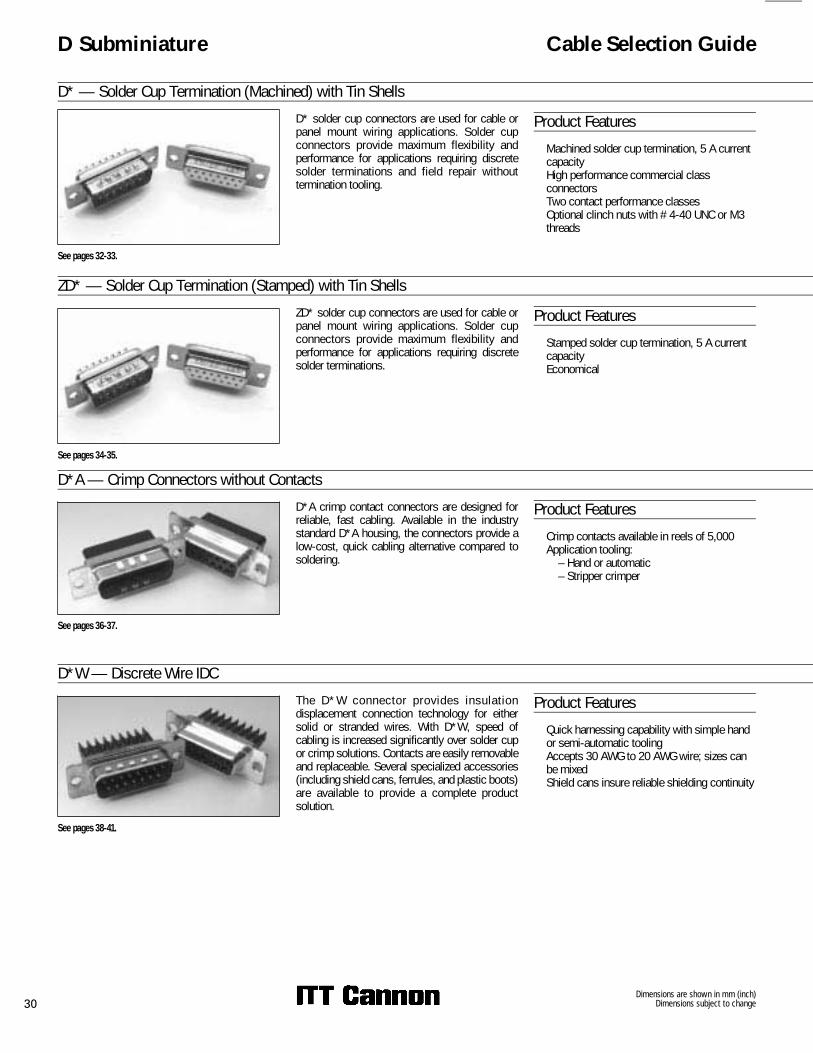
D* — Solder Cup Termination (Machined) with Tin ShellsD* solder cup connectors are used for cable orpanel mount wiring applications. Solder cupconnectors provide maximum flexibility andperformance for applications requiring discretesolder terminations and field repair withouttermination tooling.
Product Features� Machined solder cup termination, 5 A current
capacity� High performance commercial class
connectors� Two contact performance classes� Optional clinch nuts with #4-40 UNC or M3
threads
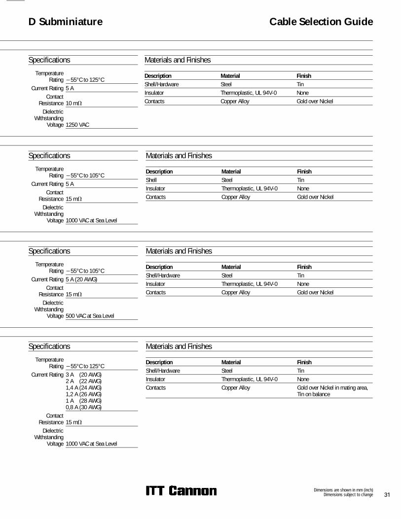
ZD* — Solder Cup Termination (Stamped) with Tin ShellsZD* solder cup connectors are used for cable orpanel mount wiring applications. Solder cupconnectors provide maximum flexibility andperformance for applications requiring discretesolder terminations.
Product Features� Stamped solder cup termination, 5 A current
capacity� Economical
D*A — Crimp Connectors without ContactsD*A crimp contact connectors are designed forreliable, fast cabling. Available in the industrystandard D*A housing, the connectors provide alow-cost, quick cabling alternative compared tosoldering.
Product Features� Crimp contacts available in reels of 5,000� Application tooling:
– Hand or automatic– Stripper crimper
D*W — Discrete Wire IDCThe D*W connector provides insulat iondisplacement connection technology for eithersolid or stranded wires. With D*W, speed ofcabling is increased significantly over solder cupor crimp solutions. Contacts are easily removableand replaceable. Several specialized accessories(including shield cans, ferrules, and plastic boots)are available to provide a complete productsolution.
Product Features� Quick harnessing capability with simple hand
or semi-automatic tooling� Accepts 30 AWG to 20 AWG wire; sizes can
be mixed� Shield cans insure reliable shielding continuity
See pages 32-33.
See pages 34-35.
See pages 36-37.
See pages 38-41.
Dimensions are shown in mm (inch)Dimensions subject to change 31
D Subminiature Cable Selection Guide
SpecificationsTemperature
Rating −55°C to 125°CCurrent Rating 5 A
ContactResistance 10 m�
DielectricWithstanding
Voltage 1250 VAC
Materials and Finishes
Description Material FinishShell/Hardware Steel TinInsulator Thermoplastic, UL 94V-0 NoneContacts Copper Alloy Gold over Nickel
SpecificationsTemperature
Rating −55°C to 105°CCurrent Rating 5 A
ContactResistance 15 m�
DielectricWithstanding
Voltage 1000 VAC at Sea Level
Materials and Finishes
Description Material FinishShell Steel TinInsulator Thermoplastic, UL 94V-0 NoneContacts Copper Alloy Gold over Nickel
SpecificationsTemperature
Rating −55°C to 105°CCurrent Rating 5 A (20 AWG)
ContactResistance 15 m�
DielectricWithstanding
Voltage 500 VAC at Sea Level
SpecificationsTemperature
Rating −55°C to 125°CCurrent Rating 3 A (20 AWG)
2 A (22 AWG)1,4 A (24 AWG)1,2 A (26 AWG)1 A (28 AWG)0,8 A (30 AWG)
ContactResistance 15 m�
DielectricWithstanding
Voltage 1000 VAC at Sea Level
Materials and Finishes
Description Material FinishShell/Hardware Steel TinInsulator Thermoplastic, UL 94V-0 NoneContacts Copper Alloy Gold over Nickel in mating area,
Tin on balance
Materials and Finishes
Description Material FinishShell/Hardware Steel TinInsulator Thermoplastic, UL 94V-0 NoneContacts Copper Alloy Gold over Nickel
Dimensions are shown in mm (inch)Dimensions subject to change32
D Subminiature D*
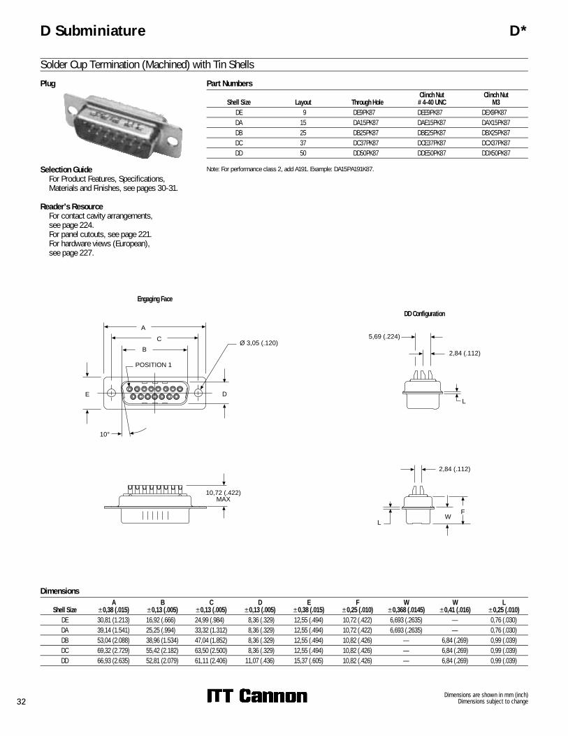
Solder Cup Termination (Machined) with Tin ShellsPart Numbers
Shell Size Layout Through HoleClinch Nut
#4-40 UNCClinch Nut
M3DE 9 DE9PK87 DEE9PK87 DEX9PK87DA 15 DA15PK87 DAE15PK87 DAX15PK87DB 25 DB25PK87 DBE25PK87 DBX25PK87DC 37 DC37PK87 DCE37PK87 DCX37PK87DD 50 DD50PK87 DDE50PK87 DDX50PK87
Note: For performance class 2, add A191. Example: DA15PA191K87.
Dimensions
Shell SizeA
±0,38 (.015)B
±0,13 (.005)C
±0,13 (.005)D
±0,13 (.005)E
±0,38 (.015)F
±0,25 (.010)W
±0,368 (.0145)W
±0,41 (.016)L
±0,25 (.010)DE 30,81 (1.213) 16,92 (.666) 24,99 (.984) 8,36 (.329) 12,55 (.494) 10,72 (.422) 6,693 (.2635) — 0,76 (.030)DA 39,14 (1.541) 25,25 (.994) 33,32 (1.312) 8,36 (.329) 12,55 (.494) 10,72 (.422) 6,693 (.2635) — 0,76 (.030)DB 53,04 (2.088) 38,96 (1.534) 47,04 (1.852) 8,36 (.329) 12,55 (.494) 10,82 (.426) — 6,84 (.269) 0,99 (.039)DC 69,32 (2.729) 55,42 (2.182) 63,50 (2.500) 8,36 (.329) 12,55 (.494) 10,82 (.426) — 6,84 (.269) 0,99 (.039)DD 66,93 (2.635) 52,81 (2.079) 61,11 (2.406) 11,07 (.436) 15,37 (.605) 10,82 (.426) — 6,84 (.269) 0,99 (.039)
Plug
Engaging Face
DD Configuration
5,69 (.224)
2,84 (.112)
L
2,84 (.112)
FW
L
Selection Guide� For Product Features, Specifications,
Materials and Finishes, see pages 30-31.
Reader’s Resource� For contact cavity arrangements,
see page 224.� For panel cutouts, see page 221.� For hardware views (European),
see page 227.
10°
DE
C
B
A
Ø 3,05 (.120)
POSITION 1
10,72 (.422)MAX

Dimensions are shown in mm (inch)Dimensions subject to change 33
D Subminiature D*
Solder Cup Termination (Machined) with Tin ShellsPart Numbers
Shell Size Layout Through HoleClinch Nut
#4-40 UNCClinch Nut
M3DE 9 DE9SA197 DEE9SA197 DEX9SA197DA 15 DA15SA197 DAE15SA197 DAX15SA197DB 25 DB25SA197 DBE25SA197 DBX25SA197DC 37 DC37SA197 DCE37SA197 DCX37SA197DD 50 DD50SA197 DDE50SA197 DDX50SA197
Note: For performance class 2, add A191. Example: DA15SA191A197.
Dimensions
Shell SizeA
±0,38 (.015)B
±0,13 (.005)C
±0,13 (.005)D
±0,13 (.005)E
±0,38 (.015)F
±0,25 (.010)W
±0,38 (.015)L
±0,25 (.010)DE 30,81 (1.213) 16,33 (.643) 24,99 (.984) 7,90 (.311) 12,55 (.494) 10,90 (.429) 6,94 (.273) 0,76 (.030)DA 39,14 (1.541) 24,66 (.971) 33,32 (1.312) 7,90 (.311) 12,55 (.494) 10,90 (.429) 6,94 (.273) 0,76 (.030)DB 53,04 (2.088) 38,38 (1.511) 47,04 (1.852) 7,90 (.311) 12,55 (.494) 10,90 (.429) 6,94 (.273) 0,76 (.030)DC 69,32 (2.729) 54,84 (2.159) 63,50 (2.500) 7,90 (.311) 12,55 (.494) 10,90 (.429) 6,94 (.273) 0,76 (.030)DD 66,93 (2.635) 52,42 (2.064) 61,11 (2.406) 10,74 (.423) 15,37 (.605) 10,90 (.429) 6,94 (.273) 0,76 (.030)
Receptacle
Engaging Face
5,69 (.224)
2,84 (.112)
L
DD Configuration
Selection Guide� For Product Features, Specifications,
Materials and Finishes, see pages 30-31.
Reader’s Resource� For contact cavity arrangements,
see page 224.� For panel cutouts, see page 221.� For hardware views (European),
see page 227.
10°
DE
C
B
A
Ø 3,05 (.120)
POSITION 1
9,91 (.390)MAX
2,84 (.112)
FW
L
Dimensions are shown in mm (inch)Dimensions subject to change34
D Subminiature ZD*
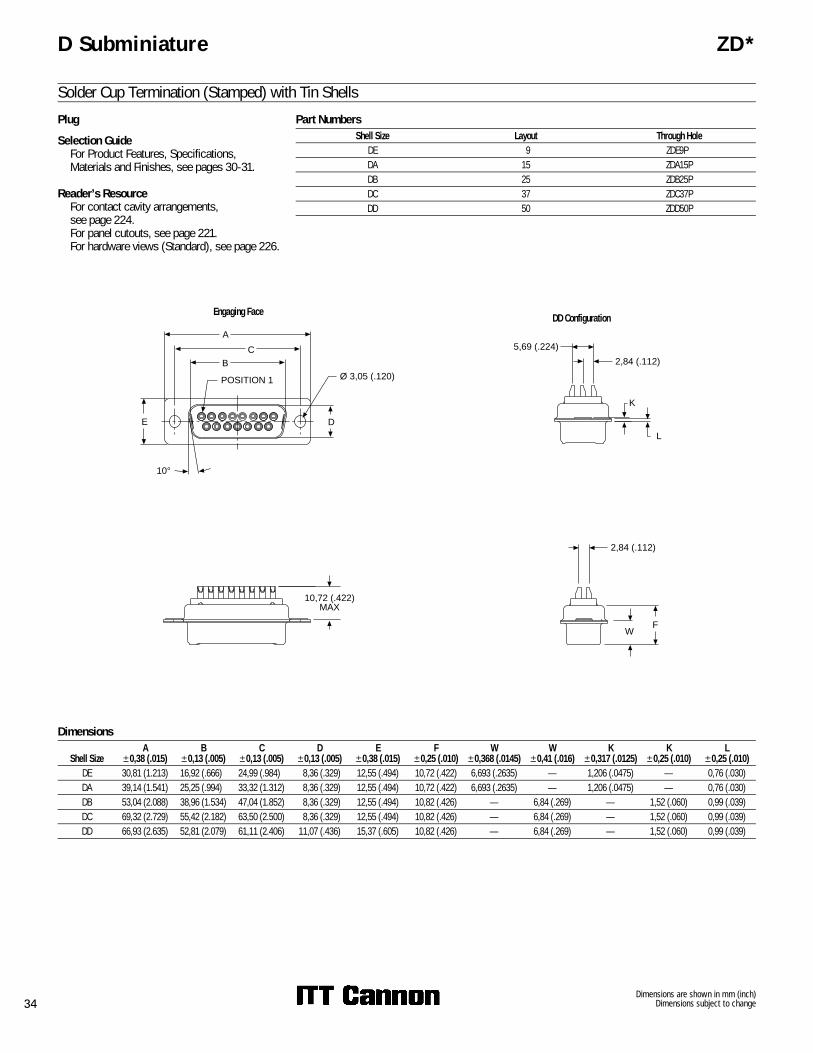
Solder Cup Termination (Stamped) with Tin ShellsPart Numbers
Shell Size Layout Through HoleDE 9 ZDE9PDA 15 ZDA15PDB 25 ZDB25PDC 37 ZDC37PDD 50 ZDD50P
Dimensions
Shell SizeA
±0,38 (.015)B
±0,13 (.005)C
±0,13 (.005)D
±0,13 (.005)E
±0,38 (.015)F
±0,25 (.010)W
±0,368 (.0145)W
±0,41 (.016)K
±0,317 (.0125)K
±0,25 (.010)L
±0,25 (.010)DE 30,81 (1.213) 16,92 (.666) 24,99 (.984) 8,36 (.329) 12,55 (.494) 10,72 (.422) 6,693 (.2635) — 1,206 (.0475) — 0,76 (.030)DA 39,14 (1.541) 25,25 (.994) 33,32 (1.312) 8,36 (.329) 12,55 (.494) 10,72 (.422) 6,693 (.2635) — 1,206 (.0475) — 0,76 (.030)DB 53,04 (2.088) 38,96 (1.534) 47,04 (1.852) 8,36 (.329) 12,55 (.494) 10,82 (.426) — 6,84 (.269) — 1,52 (.060) 0,99 (.039)DC 69,32 (2.729) 55,42 (2.182) 63,50 (2.500) 8,36 (.329) 12,55 (.494) 10,82 (.426) — 6,84 (.269) — 1,52 (.060) 0,99 (.039)DD 66,93 (2.635) 52,81 (2.079) 61,11 (2.406) 11,07 (.436) 15,37 (.605) 10,82 (.426) — 6,84 (.269) — 1,52 (.060) 0,99 (.039)
Plug
Engaging Face
Selection Guide� For Product Features, Specifications,
Materials and Finishes, see pages 30-31.
Reader’s Resource� For contact cavity arrangements,
see page 224.� For panel cutouts, see page 221.� For hardware views (Standard), see page 226.
2,84 (.112)
WF
DD ConfigurationA
CB
E D
Ø 3,05 (.120)
10°
POSITION 1
10,72 (.422)MAX
5,69 (.224)
L
2,84 (.112)
K
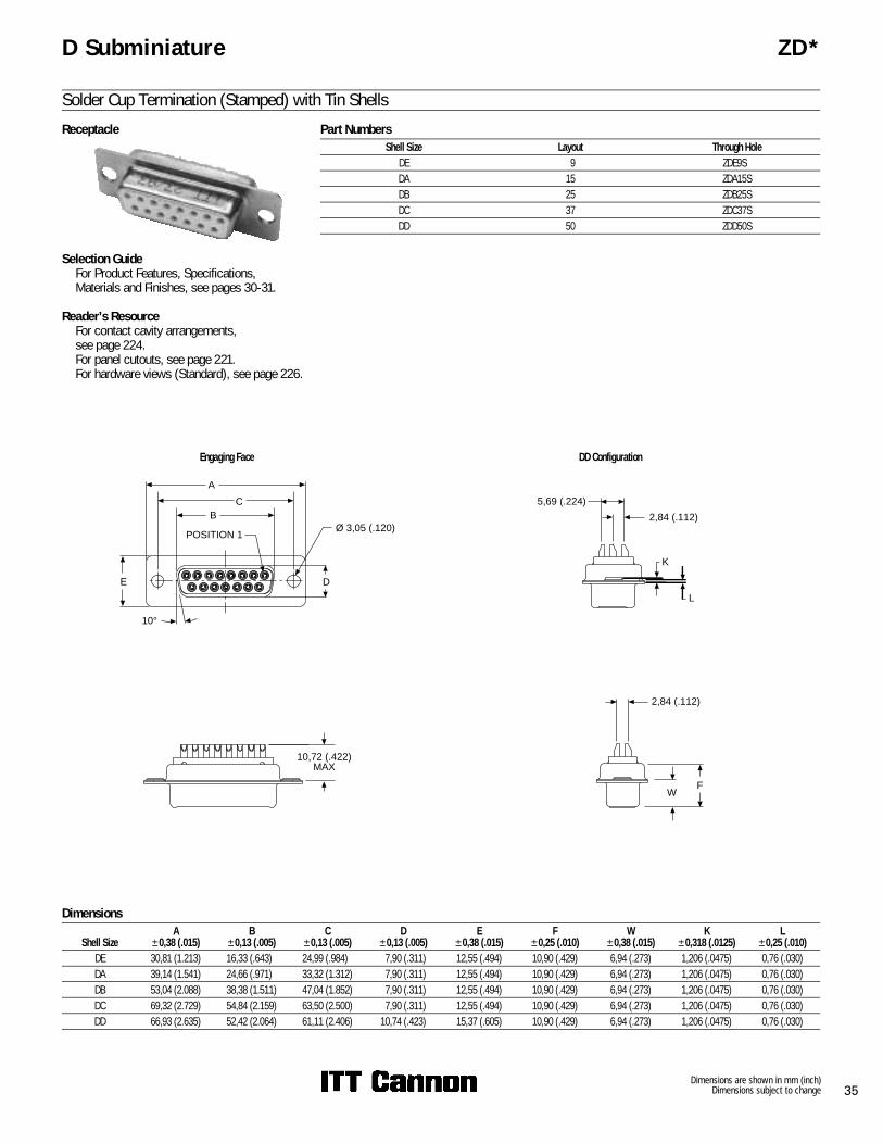
Dimensions are shown in mm (inch)Dimensions subject to change 35
D Subminiature ZD*
Solder Cup Termination (Stamped) with Tin ShellsPart Numbers
Shell Size Layout Through HoleDE 9 ZDE9SDA 15 ZDA15SDB 25 ZDB25SDC 37 ZDC37SDD 50 ZDD50S
Dimensions
Shell SizeA
±0,38 (.015)B
±0,13 (.005)C
±0,13 (.005)D
±0,13 (.005)E
±0,38 (.015)F
±0,25 (.010)W
±0,38 (.015)K
±0,318 (.0125)L
±0,25 (.010)DE 30,81 (1.213) 16,33 (.643) 24,99 (.984) 7,90 (.311) 12,55 (.494) 10,90 (.429) 6,94 (.273) 1,206 (.0475) 0,76 (.030)DA 39,14 (1.541) 24,66 (.971) 33,32 (1.312) 7,90 (.311) 12,55 (.494) 10,90 (.429) 6,94 (.273) 1,206 (.0475) 0,76 (.030)DB 53,04 (2.088) 38,38 (1.511) 47,04 (1.852) 7,90 (.311) 12,55 (.494) 10,90 (.429) 6,94 (.273) 1,206 (.0475) 0,76 (.030)DC 69,32 (2.729) 54,84 (2.159) 63,50 (2.500) 7,90 (.311) 12,55 (.494) 10,90 (.429) 6,94 (.273) 1,206 (.0475) 0,76 (.030)DD 66,93 (2.635) 52,42 (2.064) 61,11 (2.406) 10,74 (.423) 15,37 (.605) 10,90 (.429) 6,94 (.273) 1,206 (.0475) 0,76 (.030)
Receptacle
Engaging Face DD Configuration
Selection Guide� For Product Features, Specifications,
Materials and Finishes, see pages 30-31.
Reader’s Resource� For contact cavity arrangements,
see page 224.� For panel cutouts, see page 221.� For hardware views (Standard), see page 226.
2,84 (.112)
WF
A
CB
E D
Ø 3,05 (.120)
10°
POSITION 1
5,69 (.224)
L
2,84 (.112)
K
10,72 (.422)MAX

Dimensions are shown in mm (inch)Dimensions subject to change36
D Subminiature D*A
Crimp Connectors without ContactsPart Numbers
Shell Size Layout Through HoleDE 9 DEA9PK87FODA 15 DAA15PK87FODB 25 DBA25PK87FODC 37 DCA37PK87FO
Note: For crimp (size 20) contacts and tooling, see pages 83 & 275.
Dimensions
Shell SizeA
±0,38 (.015)B
±0,13 (.005)C
±0,13 (.005)D
±0,13 (.005)E
±0,38 (.015)F
±0,25 (.010)W
±0,368 (.0145)W
±0,41 (.016)K
±0,317 (.0125)K
±0,25 (.010)L
±0,25 (.010)DE 30,81 (1.213) 16,92 (.666) 24,99 (.984) 8,36 (.329) 12,55 (.494) 10,72 (.422) 6,693 (.2635) — 1,206 (.0475) — 0,76 (.030)DA 39,14 (1.541) 25,25 (.994) 33,32 (1.312) 8,36 (.329) 12,55 (.494) 10,72 (.422) 6,693 (.2635) — 1,206 (.0475) — 0,76 (.030)DB 53,04 (2.088) 38,96 (1.534) 47,04 (1.852) 8,36 (.329) 12,55 (.494) 10,82 (.426) — 6,84 (.269) — 1,52 (.060) 0,99 (.039)DC 69,32 (2.729) 55,42 (2.182) 63,50 (2.500) 8,36 (.329) 12,55 (.494) 10,82 (.426) — 6,84 (.269) — 1,52 (.060) 0,99 (.039)DD 66,93 (2.635) 52,81 (2.079) 61,11 (2.406) 11,07 (.436) 15,37 (.605) 10,82 (.426) — 6,84 (.269) — 1,52 (.060) 0,99 (.039)
Plug
Engaging Face
Selection Guide� For Product Features, Specifications,
Materials and Finishes, see pages 30-31.
Reader’s Resource� For contact cavity arrangements,
see page 224.� For panel cutouts, see page 221.� For hardware views (Standard), see page 226.
10°
DE
C
B
A
Ø 3,05 (.120)
POSITION 1
10,93 (.430)
L
K
FW

Dimensions are shown in mm (inch)Dimensions subject to change 37
D Subminiature D*A
Crimp Connectors without ContactsPart Numbers
Shell Size Layout Through HoleDE 9 DEA9SA197FODA 15 DAA15SA197FODB 25 DBA25SA197FODC 37 DCA37SA197FO
Note: For crimp (size 20) contacts and tooling, see pages 83 & 275.
Dimensions
Shell SizeA
±0,38 (.015)B
±0,13 (.005)C
±0,13 (.005)D
±0,13 (.005)E
±0,38 (.015)F
±0,25 (.010)W
±0,38 (.015)K
±0,318 (.0125)L
±0,25 (.010)DE 30,81 (1.213) 16,33 (.643) 24,99 (.984) 7,90 (.311) 12,55 (.494) 10,90 (.429) 6,94 (.273) 1,206 (.0475) 0,76 (.030)DA 39,14 (1.541) 24,66 (.971) 33,32 (1.312) 7,90 (.311) 12,55 (.494) 10,90 (.429) 6,94 (.273) 1,206 (.0475) 0,76 (.030)DB 53,04 (2.088) 38,38 (1.511) 47,04 (1.852) 7,90 (.311) 12,55 (.494) 10,90 (.429) 6,94 (.273) 1,206 (.0475) 0,76 (.030)DC 69,32 (2.729) 54,84 (2.159) 63,50 (2.500) 7,90 (.311) 12,55 (.494) 10,90 (.429) 6,94 (.273) 1,206 (.0475) 0,76 (.030)DD 66,93 (2.635) 52,42 (2.064) 61,11 (2.406) 10,74 (.423) 15,37 (.605) 10,90 (.429) 6,94 (.273) 1,206 (.0475) 0,76 (.030)
Receptacle
10°
E
C
B
A
D
Ø 3,05 (.120)
POSITION 1
10,93 (.430)
Engaging Face
Selection Guide� For Product Features, Specifications,
Materials and Finishes, see pages 30-31.
Reader’s Resource� For contact cavity arrangements,
see page 224.� For panel cutouts, see page 221.� For hardware views (Standard), see page 226.
LF
W
K

Dimensions are shown in mm (inch)Dimensions subject to change80
D Subminiature Combo D
Crimp Cable Connectors without Contacts (Sizes DA-DD)Plug
Reader’s Resource� For contact cavity arrangements,
see page 222.� For panel cutouts, see page 221.
Part NumbersShell Size Layout Part Number
DA 7W2 DAA7W2PK87F0DA 11W1 DAA11W1PK87F0DA 3W3 DAA3W3PK87F0DB 5W5 DBA5W5PK87F0DB 9W4 DBA9W4PK87F0DB 13W3 DBA13W3PK87F0DB 17W2 DBA17W2PK87F0DB 21W1 DBA21W1PK87F0DC 8W8 DCA8W8PK87F0DC 21WA4 DCA21WA4PK87F0DC 25W3 DCA25W3PK87F0DD 24W7 DDA24W7PK87F0DD 36W4 DDA36W4PK87F0
Note: For crimp (Size 20) contacts and tooling, see pages 83 & 275.
Dimensions
Shell SizeA
±0,38 (.015)B
±0,13 (.005)C
±0,13 (.005)D
±0,13 (.005)E
±0,38 (.015)F
±0,25 (.010)W
±0,368 (.0145)W
±0,41 (.016)K
±0,317 (.0125)K
±0,25 (.010)L
±0,25 (.010)DE 30,81 (1.213) 16,92 (.666) 24,99 (.984) 8,36 (.329) 12,55 (.494) 10,72 (.422) 6,693 (.2635) — 1,206 (.0475) — 0,76 (.030)DA 39,14 (1.541) 25,25 (.994) 33,32 (1.312) 8,36 (.329) 12,55 (.494) 10,72 (.422) 6,693 (.2635) — 1,206 (.0475) — 0,76 (.030)DB 53,04 (2.088) 38,96 (1.534) 47,04 (1.852) 8,36 (.329) 12,55 (.494) 10,82 (.426) — 6,84 (.269) — 1,52 (.060) 0,99 (.039)DC 69,32 (2.729) 55,42 (2.182) 63,50 (2.500) 8,36 (.329) 12,55 (.494) 10,82 (.426) — 6,84 (.269) — 1,52 (.060) 0,99 (.039)DD 66,93 (2.635) 52,81 (2.079) 61,11 (2.406) 11,07 (.436) 15,37 (.605) 10,82 (.426) — 6,84 (.269) — 1,52 (.060) 0,99 (.039)
Engaging Face
L
K10,92 (.430)
MAX
A
C
B
E D
10°
Dimensions are shown in mm (inch)Dimensions subject to change 81
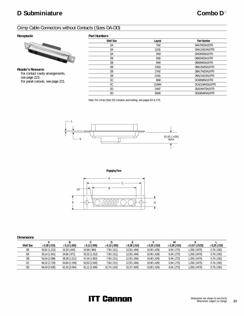
D Subminiature Combo D
Crimp Cable Connectors without Contacts (Sizes DA-DD)Receptacle
Reader’s Resource� For contact cavity arrangements,
see page 223.� For panel cutouts, see page 221.
Part NumbersShell Size Layout Part Number
DA 7W2 DAA7W2SA197F0DA 11W1 DAA11W1SA197F0DA 3W3 DAA3W3SA197F0DB 5W5 DBA5W5SA197F0DB 9W4 DBA9W4SA197F0DB 13W3 DBA13W3SA197F0DB 17W2 DBA17W2SA197F0DB 21W1 DBA21W1SA197F0DC 8W8 DCA8W8SA197F0DC 21WA4 DCA21WA4SA197F0DD 24W7 DDA24W7SA197F0DD 36W4 DDA36W4SA197F0
Note: For crimp (Size 20) contacts and tooling, see pages 83 & 275.
Dimensions
Shell SizeA
±0,38 (.015)B
±0,13 (.005)C
±0,13 (.005)D
±0,13 (.005)E
±0,38 (.015)F
±0,25 (.010)W
±0,38 (.015)K
±0,317 (.0125)L
±0,25 (.010)DE 30,81 (1.213) 16,33 (.643) 24,99 (.984) 7,90 (.311) 12,55 (.494) 10,90 (.429) 6,94 (.273) 1,206 (.0475) 0,76 (.030)DA 39,14 (1.541) 24,66 (.971) 33,32 (1.312) 7,90 (.311) 12,55 (.494) 10,90 (.429) 6,94 (.273) 1,206 (.0475) 0,76 (.030)DB 53,04 (2.088) 38,38 (1.511) 47,04 (1.852) 7,90 (.311) 12,55 (.494) 10,90 (.429) 6,94 (.273) 1,206 (.0475) 0,76 (.030)DC 69,32 (2.729) 54,84 (2.159) 63,50 (2.500) 7,90 (.311) 12,55 (.494) 10,90 (.429) 6,94 (.273) 1,206 (.0475) 0,76 (.030)DD 66,93 (2.635) 52,42 (2.064) 61,11 (2.406) 10,74 (.423) 15,37 (.605) 10,90 (.429) 6,94 (.273) 1,206 (.0475) 0,76 (.030)
Engaging Face
L
K10,92 (.430)
MAX
A
C
B
E D
10°
Dimensions are shown in mm (inch)Dimensions subject to change82
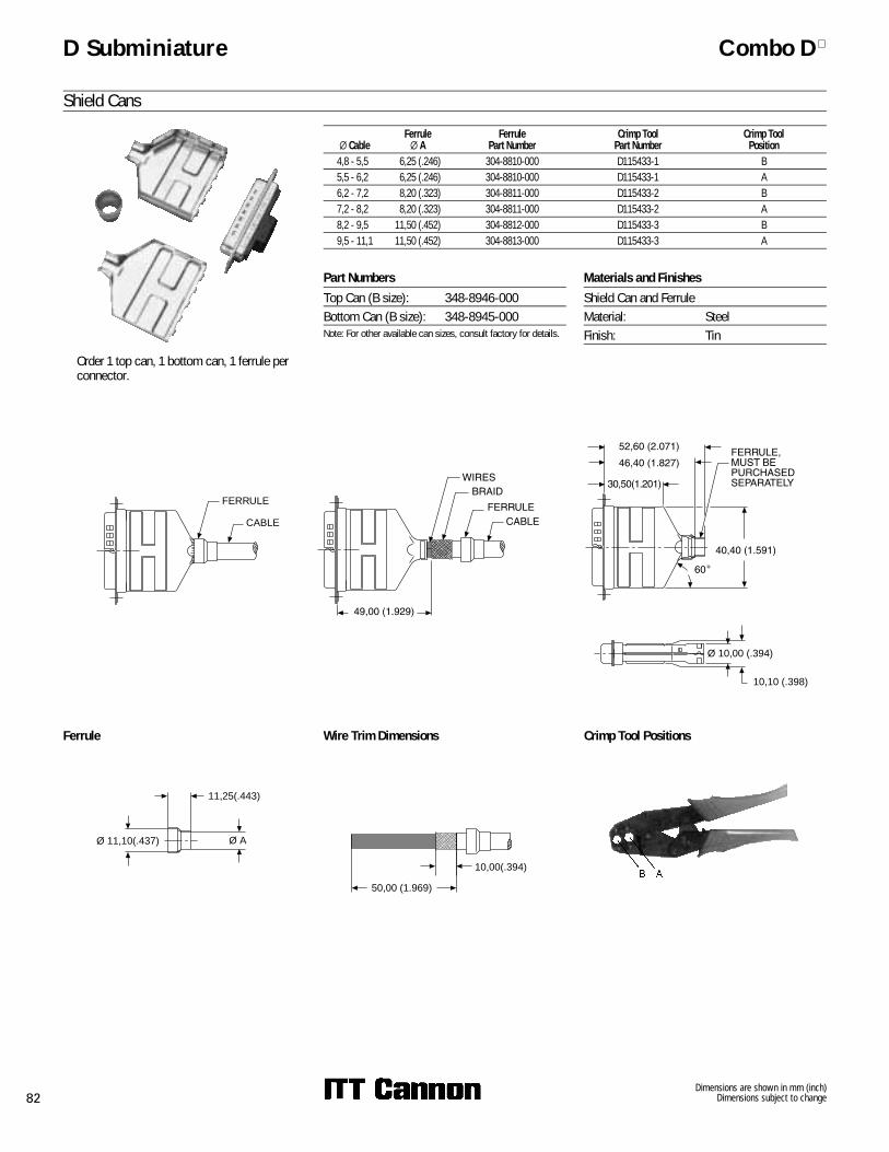
D Subminiature Combo D
Shield Cans
X CableFerrule
X AFerrule
Part NumberCrimp Tool
Part NumberCrimp Tool
Position4,8 - 5,5 6,25 (.246) 304-8810-000 D115433-1 B5,5 - 6,2 6,25 (.246) 304-8810-000 D115433-1 A6,2 - 7,2 8,20 (.323) 304-8811-000 D115433-2 B7,2 - 8,2 8,20 (.323) 304-8811-000 D115433-2 A8,2 - 9,5 11,50 (.452) 304-8812-000 D115433-3 B9,5 - 11,1 11,50 (.452) 304-8813-000 D115433-3 A
FERRULE
CABLE
Ferrule Wire Trim Dimensions
11,25(.443)
Ø AØ 11,10(.437)
10,00(.394)
50,00 (1.969)
Crimp Tool Positions
10,10 (.398)
Ø 10,00 (.394)
� Order 1 top can, 1 bottom can, 1 ferrule perconnector.
Materials and FinishesShield Can and FerruleMaterial: SteelFinish: Tin
Part NumbersTop Can (B size): 348-8946-000Bottom Can (B size): 348-8945-000Note: For other available can sizes, consult factory for details.

Dimensions are shown in mm (inch)Dimensions subject to change 83
Loose ContactsStamped contacts with insulation support aresupplied loose for use with hand crimp tooling.Two sizes are available to accommodate wireranges 20 - 26 AWG.
D Subminiature Combo D
Crimp (Size 20) Contacts
ToolingHand Crimp Tool
Description Part NumberCCT-D*A-1 995-2000-000
Extraction ToolDescription Part Number Wire Size
CIET-D*A-20-24 980-0008-135 20-24 AWGCIET-D*A-24-26 980-0008-136 24-26 AWG
For semi-automatic tooling, see page 275.
CCT-D*A-1
Pin Contact Socket Contact
Finish30� inches Gold over Nickel
For tooling, see this page.
Part NumberPin Contact
24-26 AWG 20-24 AWG030-2487-017 030-2487-016
Part NumberSocket Contact
24-26 AWG 20-24 AWG030-2488-017 030-2488-016
Reeled Contacts (5,000 Pieces per Reel)Stamped contacts with insulation support aresupplied on reels of 5,000 for use with semi-automatic strip and crimp machines. Two sizes areavailable to accommodate wire ranges 20 - 26AWG.
Pin Contacts Socket Contacts
FinishGold over Nickel30� inches Gold over Nickel
For semi-automatic tooling, see page 275.
Part NumberPin Contact
24-26 AWG 20-24 AWG980-2000-925 980-2000-924980-2000-946 980-2000-945
Part NumberSocket Contact
24-26 AWG 20-24 AWG980-2000-926 980-2000-923980-2000-944 980-2000-943
Pin Contacts Socket Contacts
Dimensions are shown in mm (inch)Dimensions subject to change84
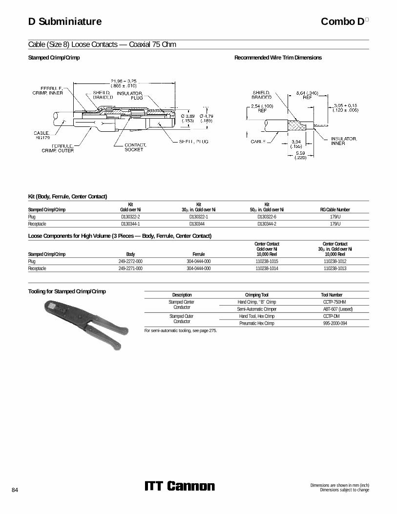
D Subminiature Combo D
Cable (Size 8) Loose Contacts — Coaxial 75 OhmStamped Crimp/Crimp Recommended Wire Trim Dimensions
Kit (Body, Ferrule, Center Contact)
Stamped Crimp/CrimpKit
Gold over NiKit
30� in. Gold over NiKit
50� in. Gold over Ni RG Cable NumberPlug D130322-2 D130322-1 D130322-6 179/UReceptacle D130344-1 D130344 D130344-2 179/U
Tooling for Stamped Crimp/Crimp Description Crimping Tool Tool NumberStamped Center
ConductorHand Crimp, ‘‘B’’ Crimp CCTP-750HMSemi-Automatic Crimper ABT-607 (Leased)
Stamped Outer Conductor
Hand Tool, Hex Crimp CCTP-DMPneumatic Hex Crimp 995-2000-094
For semi-automatic tooling, see page 275.
Loose Components for High Volume (3 Pieces — Body, Ferrule, Center Contact)
Stamped Crimp/Crimp Body Ferrule
Center ContactGold over Ni10,000 Reel
Center Contact30� in. Gold over Ni
10,000 ReelPlug 249-2272-000 304-0444-000 110238-1015 110238-1012Receptacle 249-2271-000 304-0444-000 110238-1014 110238-1013

Dimensions are shown in mm (inch)Dimensions subject to change 85
D Subminiature Combo D
Cable (Size 8) Loose Contacts — Coaxial 75 Ohm — 90°90° Crimp Braid/Solder Center Contact Part Number Part Number Part Number
Gold over Ni 30� in. Gold over Ni 50� in. Gold over NiPlug D130357-1 D130357 D130357-4Receptacle D130356-1 D130356 D130356-3
Plug Receptacle
Tooling for 90° Crimp Braid
Description Part NumberHand Tool: 995-0001-761Die Set: 995-2000-110
17,30 (.680)REF
0,16 (.006)REF
Ø 4,79(.189)REF
17,53 (.690)REF
5,10 (.200)REF
Note: Ferrule not shown. Note: Ferrule not shown.
Dimensions are shown in mm (inch)Dimensions subject to change86
D Subminiature Combo D
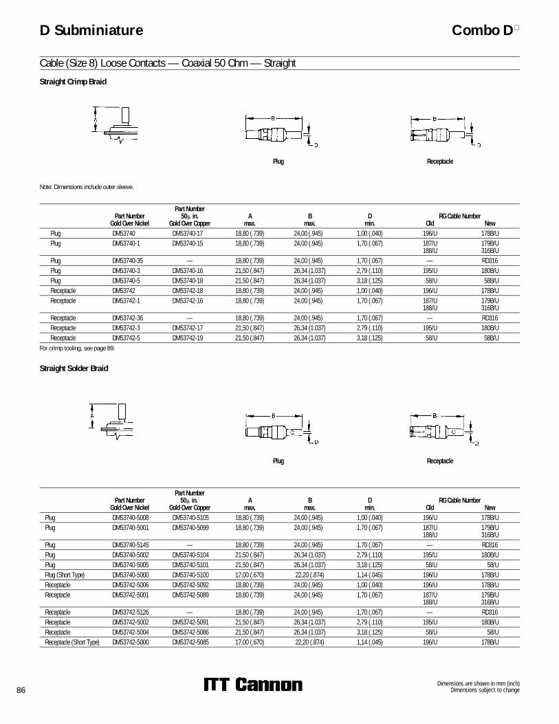
Cable (Size 8) Loose Contacts — Coaxial 50 Ohm — StraightStraight Crimp Braid
Part NumberGold Over Nickel
Part Number50� in.
Gold Over CopperA
max.B
max.D
min.RG Cable Number
Old NewPlug DM53740 DM53740-17 18,80 (.739) 24,00 (.945) 1,00 (.040) 196/U 178B/UPlug DM53740-1 DM53740-15 18,80 (.739) 24,00 (.945) 1,70 (.067) 187/U
188/U179B/U316B/U
Plug DM53740-35 — 18,80 (.739) 24,00 (.945) 1,70 (.067) — RD316Plug DM53740-3 DM53740-16 21,50 (.847) 26,34 (1.037) 2,79 (.110) 195/U 180B/UPlug DM53740-5 DM53740-18 21,50 (.847) 26,34 (1.037) 3,18 (.125) 58/U 58B/UReceptacle DM53742 DM53742-18 18,80 (.739) 24,00 (.945) 1,00 (.040) 196/U 178B/UReceptacle DM53742-1 DM53742-16 18,80 (.739) 24,00 (.945) 1,70 (.067) 187/U
188/U179B/U316B/U
Receptacle DM53742-36 — 18,80 (.739) 24,00 (.945) 1,70 (.067) — RD316Receptacle DM53742-3 DM53742-17 21,50 (.847) 26,34 (1.037) 2,79 (.110) 195/U 180B/UReceptacle DM53742-5 DM53742-19 21,50 (.847) 26,34 (1.037) 3,18 (.125) 58/U 58B/U
For crimp tooling, see page 89.
Straight Solder Braid
Part NumberGold Over Nickel
Part Number50� in.
Gold Over CopperA
max.B
max.D
min.RG Cable Number
Old NewPlug DM53740-5008 DM53740-5105 18,80 (.739) 24,00 (.945) 1,00 (.040) 196/U 178B/UPlug DM53740-5001 DM53740-5099 18,80 (.739) 24,00 (.945) 1,70 (.067) 187/U
188/U179B/U316B/U
Plug DM53740-5145 — 18,80 (.739) 24,00 (.945) 1,70 (.067) — RD316Plug DM53740-5002 DM53740-5104 21,50 (.847) 26,34 (1.037) 2,79 (.110) 195/U 180B/UPlug DM53740-5005 DM53740-5101 21,50 (.847) 26,34 (1.037) 3,18 (.125) 58/U 58/UPlug (Short Type) DM53740-5000 DM53740-5100 17,00 (.670) 22,20 (.874) 1,14 (.045) 196/U 178B/UReceptacle DM53742-5006 DM53742-5092 18,80 (.739) 24,00 (.945) 1,00 (.040) 196/U 178B/UReceptacle DM53742-5001 DM53742-5089 18,80 (.739) 24,00 (.945) 1,70 (.067) 187/U
188/U179B/U316B/U
Receptacle DM53742-5126 — 18,80 (.739) 24,00 (.945) 1,70 (.067) — RD316Receptacle DM53742-5002 DM53742-5091 21,50 (.847) 26,34 (1.037) 2,79 (.110) 195/U 180B/UReceptacle DM53742-5004 DM53742-5086 21,50 (.847) 26,34 (1.037) 3,18 (.125) 58/U 58/UReceptacle (Short Type) DM53742-5000 DM53742-5085 17,00 (.670) 22,20 (.874) 1,14 (.045) 196/U 178B/U
ReceptaclePlug
Plug Receptacle
Note: Dimensions include outer sleeve.

Dimensions are shown in mm (inch)Dimensions subject to change 87
D Subminiature Combo D
Cable (Size 8) Loose Contacts — Coaxial 50 Ohm — 90°90° Crimp Braid
Note: Dimensions include outer sleeve.
Plug Receptacle
Part NumberGold Over Nickel
Part Number50� in. Gold Over Copper
Amax.
Bmax. C
D±0,13 (.005)
RG Cable NumberOld New
Plug DM53741 DM53741-12 13,46 (.530) 18,92 (.745) 15,10 (.594) 1,14 (.045) 196/U 178B/UPlug DM53741-1 DM53741-11 13,46 (.530) 18,92 (.745) 15,10 (.594) 1,83 (.072) 187/U
188/U179B/U316B/U
Plug DM53741-3 DM53741-10 13,46 (.530) 18,92 (.745) 16,00 (.630) 2,79 (.110) 195/U 180B/UPlug DM53741-4 DM53741-13 13,46 (.530) 18,92 (.745) 16,00 (.630) 3,18 (.125) 58/U 58B/UReceptacle DM53743-2 DM53743-18 13,46 (.530) 18,92 (.745) 15,09 (.594) 1,14 (.045) 196/U 178B/UReceptacle DM53743-3 DM53743-16 13,46 (.530) 18,92 (.745) 15,09 (.594) 1,83 (.072) 187/U
188/U179B/U316B/U
Receptacle DM53743-5 DM53743-17 13,46 (.530) 18,92 (.745) 16,00 (.630) 2,79 (.110) 195/U 180B/UReceptacle DM53743-6 DM53743-19 13,46 (.530) 18,92 (.745) 16,00 (.630) 3,18 (.125) 58/U 58B/U
For crimp tooling, see page 89.
90° Solder Braid
Plug Receptacle
Part NumberGold Over Nickel
Part Number50� in. Gold Over Copper
Amax.
Bmax. C
Dmin.
RG Cable NumberOld New
Plug DM53741-5000 DM53741-5059 13,46 (.530) 18,92 (.745) 15,10 (.594) 1,00 (.040) 196/U 178B/UPlug DM53741-5001 DM53741-5062 13,46 (.530) 18,92 (.745) 15,10 (.594) 1,70 (.067) 187/U
188/U179B/U316B/U
Plug DM53741-5003 DM53741-5063 13,46 (.530) 18,92 (.745) 16,00 (.630) 2,79 (.110) 195/U 180B/UPlug DM53741-5004 DM53741-5060 13,46 (.530) 18,92 (.745) 16,00 (.630) 3,18 (.125) 58/U 58/UReceptacle DM53743-5000 DM53743-5073 13,46 (.530) 18,92 (.745) 15,09 (.594) 1,00 (.040) 196/U 178B/UReceptacle DM53743-5001 DM53743-5076 13,46 (.530) 18,92 (.745) 15,09 (.594) 1,70 (.067) 187/U
188/U179B/U316B/U
Receptacle DM53743-5003 DM53743-5077 13,46 (.530) 18,92 (.745) 16,00 (.630) 2,79 (.110) 195/U 180B/UReceptacle DM53743-5004 DM53743-5074 13,46 (.530) 18,92 (.745) 16,00 (.630) 3,18 (.125) 58/U 58B/U

Dimensions are shown in mm (inch)Dimensions subject to change88
D Subminiature Combo D
Insertion/Extraction Instructions for Coaxial, High Power and High Voltage ContactsInsertion ToolNo insertion tool is required. The contact is easilysnapped in from the rear of the connectormanually.
Extraction Tool
The CET-C6B-2 tool extracts all coaxial, highpower and high voltage contacts (plug andreceptacle).
Description Part NumberCET-C6B-2 070064-0002
Operating Instructions
To extract the coaxial contact, hold the tool by thebody and insert the tip into the front of the contactcavity until it bottoms and closes the coaxialretaining ring. Holding the body in this position
CET-C6B-2
securely enough to keep coaxial retaining ringclosed, push the plunger; contact will be pushedout of the rear of the assembly.
Insertion Instructions

Dimensions are shown in mm (inch)Dimensions subject to change 89
D Subminiature Combo D
Coaxial Assembly Instructions
RG Cable Number
Straight Coaxial 90° CoaxialN
± 0,25 (.010)O
± 0,25 (.010)P
± 0,25 (.010)N
± 0,25 (.010)O
± 0,25 (.010)P
± 0,25 (.010)196/U, 178B/U, 187/U,188/U, 179B/U, 316B/U 7,92 (.312) 6,35 (.250) 1,98 (.078) 9,52 (.375) 5,94 (.234) 1,57 (.062)195/U, 180B/U,58/U, 58B/U 9,52 (.375) 7,92 (.312) 1,98 (.078) 10,69 (.422) 7,92 (.312) 2,39 (.094)
Coaxial Cable Trim Dimensions
RG Cable Number Tool Part Number Description Closure196/U, 178B/U 070051-0000 CCT-DM C187/U, 179B/U,188/U, 316B/U 070051-0000 CCT-DM B195/U, 180B/U,58/U, 58B/U 070051-0000 CCT-DM A
Crimp Tooling
Straight and 90° Coaxial AssemblySTEP 1: Slide the outer ring over the cable jacket. Trim thecable as specified in the table of Coaxial Cable TrimDimensions (see this page). Insert the cabledielectric and center conductor into the insidediameter of the inner sleeve. Then solder the centerconductor to the coaxial center contact.
Straight and 90° Coaxial AssemblySTEP 2: Slide the outer ring forward until it is flush with thecoaxial shell containing the braid between the outerring and the inner sleeve. For solder type coaxes,soft solder the outer ring to the assembly throughthe cross-drilled solder hold. For crimp typecoaxes, crimp with the appropriate tool in the areadefined.
Straight Coaxial 90° Coaxial
Straight Coaxial 90° Coaxial
Hand tool with integral die set for all coaxial straightcrimp braid.

Dimensions are shown in mm (inch)Dimensions subject to change90
20,93 - 20,42(.824 - .804)
Ø AØ B
D Subminiature Combo D
Cable (Size 8) Loose Contacts — High Power — SolderPlug
Part NumberGold Over Nickel
Part Number50� in. Gold over Ni Current Rating
Wire Size
DM53745-1 DM53745-28 40 A 8 AWGDM53745-7 DM53745-27 20 A 12 AWGDM53745-8 DM53745-25 10 A 16 AWG
Receptacle
Part NumberGold Over Nickel
Part Number50� in. Gold over Ni Current Rating
Wire Size
DM53744-1 DM53744-21 40 A 8 AWGDM53744-6 DM53744-25 20 A 12 AWGDM53744-7 DM53744-24 10 A 16 AWG
Plug Recommended Wire Trim Length
Part NumberGold Over Nickel
Part Number30� in. Gold over Ni
Part Number50� in. Gold over Ni
XAmax.
XBmax.
Current Rating
Wire Size
DM130338-4 DM130338 DM130338-1 4,60 (.181) 5,84 (.230) 40 A 8 AWGDM130339-4 DM130339 DM130339-1 2,54 (.100) 5,54 (.218) 20 A 12 AWGDM130340-4 DM130340 DM130340-1 1,07 (.067) 2,59 (.102) 10 A 16 AWG
Receptacle
Part NumberGold Over Nickel
Part Number30� in. Gold over Ni
Part Number50� in. Gold over Ni
XAmax.
XBmax.
Current Rating
Wire Size
DM130341-4 DM130341 DM130341-1 4,60 (.181) 5,84 (.230) 40 A 8 AWGDM130342-4 DM130342 DM130342-1 2,54 (.100) 5,54 (.218) 20 A 12 AWGDM130343-4 DM130343 DM130343-1 1,07 (.067) 2,59 (.102) 10 A 16 AWG
High Power Crimp Tooling
Crimp Tool/LocatorWire Size
Crimp Tool
Tool Setting Number Locator
8 AWG M300-BT 6 TP96810 AWG M300-BT 5 TP968
12/14 AWG M300-BT 1 TP96816 AWG FT-8 6 TH55418 AWG FT-8 5 TH554
Cable (Size 8) Loose Contacts — High Power — Crimp
M300-BT
Recommended Wire Trim Length

Dimensions are shown in mm (inch)Dimensions subject to change 91
RING, RETAINERINSULATOR
17,70 (.697)REF
Receptacle
For tooling, see page 88.
18,64 (.734)REF
RING, RETAINING
INSULATOR
D Subminiature Combo D
Cable (Size 8) Loose Contacts — High Voltage — Straight
Part Number Part Number WireSizeGold over Ni 50� in. Gold
DM51157 DM51157-8 20 AWG
Part Number Part Number WireSizeGold over Ni 50� in. Gold
DM51157-5000 DM51157-5005 20 AWG
RING, RETAINING
INSULATOR
17,70 (.697)REF
For tooling, see page 88.
For tooling, see page 88.
Plug
Receptacle19,41(.764)
REF
RING, RETAININGINSULATOR
Part Number Part Number WireSizeGold over Ni 50� in. Gold
DM51155 DM51155-7 20 AWG
For tooling, see page 88.
Cable (Size 8) Loose Contacts — High Voltage — 90°Plug
Part Number Part Number WireSizeGold over Ni 50� in. Gold
DM51155-5000 DM51155-5004 20 AWG
Dimensions are shown in mm (inch)Dimensions subject to change92
D Subminiature Combo D
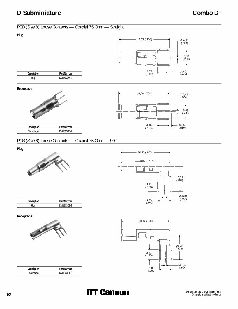
PCB (Size 8) Loose Contacts — Coaxial 75 Ohm — StraightPlug
Receptacle
PCB (Size 8) Loose Contacts — Coaxial 75 Ohm — 90°Plug
Receptacle
17,78 (.700) Ø 0,51(.020)
5,08(.200)
0,25(.010)
4,19(.165)
18,00 (.708) Ø 0,61(.024)
5,08(.200)
0,25(.010)
4,19(.165)
20,32 (.800)
3,81(.150)
10,26(.404)
Ø 0,51(.020)5,08
(.200)
20,32 (.800)
3,81(.150)
10,23(.403)
Ø 0,61(.024)5,08
(.200)
Description Part NumberPlug DM130358-2
Description Part NumberReceptacle DM130346-2
Description Part NumberPlug DM130352-2
Description Part NumberReceptacle DM130321-3
Dimensions are shown in mm (inch)Dimensions subject to change 93
D Subminiature Combo D
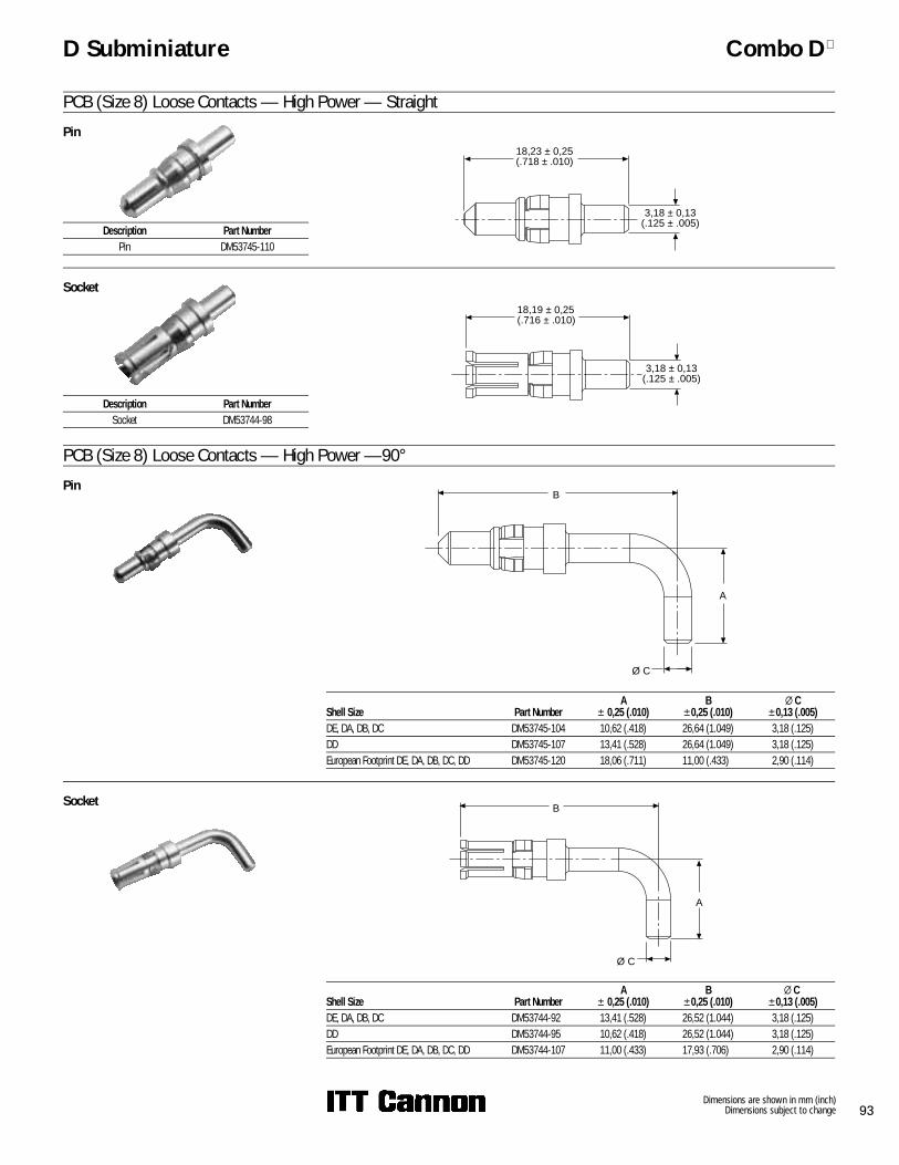
PCB (Size 8) Loose Contacts — High Power — StraightPin
Socket
PCB (Size 8) Loose Contacts — High Power —90°Pin
Shell Size Part NumberA
± 0,25 (.010)B
±0,25 (.010)X C
±0,13 (.005)DE, DA, DB, DC DM53745-104 10,62 (.418) 26,64 (1.049) 3,18 (.125)DD DM53745-107 13,41 (.528) 26,64 (1.049) 3,18 (.125)European Footprint DE, DA, DB, DC, DD DM53745-120 18,06 (.711) 11,00 (.433) 2,90 (.114)
18,23 ± 0,25(.718 ± .010)
3,18 ± 0,13(.125 ± .005)
18,19 ± 0,25(.716 ± .010)
3,18 ± 0,13(.125 ± .005)
Ø C
A
B
Ø C
B
A
Socket
Shell Size Part NumberA
± 0,25 (.010)B
±0,25 (.010)X C
±0,13 (.005)DE, DA, DB, DC DM53744-92 13,41 (.528) 26,52 (1.044) 3,18 (.125)DD DM53744-95 10,62 (.418) 26,52 (1.044) 3,18 (.125)European Footprint DE, DA, DB, DC, DD DM53744-107 11,00 (.433) 17,93 (.706) 2,90 (.114)
Description Part NumberPin DM53745-110
Description Part NumberSocket DM53744-98

Dimensions are shown in mm (inch)Dimensions subject to change94
D Subminiature Combo D
PCB (Size 8) Loose Contacts — High Voltage — StraightPlug
Part NumberGold over Ni
Part Number50� in. Gold
DM51157-13 DM51157-14
15,95 (.628)REF
5,94 - 5,44(.234 - .214)
1,52 - 1,27(.060 - .050)
Ø 3,68 - 3,53(.145 -.139)
Ø 1,65 - 1,50(.065 - .059)
Ø 5,72 - 5,33(.225 - .210)
Ø 4,88 (.192)MAX
CONTACT, PIN
INSULATOR
RING, RETAINING
16,76 (.660)REF
6,48 - 6,22(.255 - .245)
0,25 - 0,00(.010 - .000)
Ø 1,65 - 1,50(.065 - .059)
Ø 5,72 - 5,33(.225 - .210)
Ø 4,88 (.192)MAX
CONTACT, SKT
INSULATOR
RING, RETAINING
Receptacle
Part Number Gold over Ni
Part Number 50� in. Gold
DM51155-12 DM51155-13

Dimensions are shown in mm (inch)Dimensions subject to change 95
D Subminiature Combo D
PCB Guide Pin and Socket
Installs into any Combo D, Size 8 cavity. This guidepin and socket system is ideal for blind mateapplications where space is limited.
PCB Guide Pin
Part Number Material FinishDM53745-126 Copper Alloy Tin
29,21 (1.150)REF
3,68 - 3,43(.145 - .135)
Ø 5,66 - 5,41(.223 - .213)
RING, RETAINING
Ø 3,25 - 3,10(.128 - .122)
11,43 (.450)REF
PCB Guide Socket
Part Number Material Finish248-2967-000 Copper Alloy Tin
4,06 (.160)
16,28 (.641)REF
CONNECTOR REARINSULATOR REF