d-r126 archaeological t.est excavations phase …
TRANSCRIPT

D-R126 862 ARCHAEOLOGICAL T.EST EXCAVATIONS PHASE 11 TESTING AT THE 1/2HAGERMAN NRTIONRL..CU) EASTERN WASHINGTON UNIV CHENEY0 A LOTHSON ET AL. FEB 81 1-2 DACNB-81-C-926
UNCLASSIFIED .F/G 5/9 N
IhmmEmohhhhEsomhEmhhhhhEmsoEhhI-EhhhhphII
iiiiiiiiiiIi

w.7
.4. - S I - . -' *I *-, -
l§2.2
. /
.9X
[Q6
+o9. 1.
|I-41.5 LA~2 W111.
MICROCOPY RESOLUTION TEST CHART"" NATIONAL BURE.AU OF STANDARDS- 1963-A
.... 13
- .I
11111 _ -,I 13k .--'1 ma
'.9 ° -o
...1 I
., + I- .+ : - .: .+ . . . .. .. .. .
i i~i .. .IN.. .. Z

ARCAE-.L- -CL TES' EXCAVAT::NSPHASE 'rESTI:NG AT 7HE
:-iAGMMAN NAT13NAI, -- 'H -PyHAGERYAN VALLEY, :)A.HC
byCordon Allan :,othson
andKeith Allen % irga
Harvey 3. RiceP"rinc-Dal :nvesti. ator
Contract #DA0i-1-0C-0026
In., TV
~ .iA.
-At .,
1.,tot

jDITC TI CUnawfnned 0 Prepared forJustuiogti: Walla Walla District
jyj~f~q at, 6DU.S. Army Corps of Engineers1 Walla Walla, Washington 99362
AvailabilitY C0403iAvail and/or
it Special
0#
ARCHAEOLOGICAL TEST EXCAVATIONSPHASE II TESTING AT THE
HAGERMAN NATIONAL FISH HATCHERYHAGERMAN VALlEY, IDAHO
byGordon Allan Lothson
andKeith Allen Virga
Harvey S. RicePrincipal Investigator
Contract #DA 4 -81-C-0026February, 1981
0
DTICS ELECTE
APR 14193D
D
Report Number 1-2Eastern Washington University Reports in Archaeology and History
Cheney, Washington 99004iAAprovod for public roloesm
~i ribultiOn Unlinited

- *4
2 -4
r-4 4
-
0 >
co
0
) 4
0q
or--

46-

ABSTRACT
* It is suggested in this report that portions of the Hagerman NationalFish Hatchery site are a significant and important multicomponent archaeo-logical site. Data collected by Max G. Pavesic and Daniel S. Meatte indi-cated the existence of extensive occupation, and they recognized seven po-tentially significant localities. One of these seven localities, not testedby Pavesic and Meatte, was examined during this Phase II study; as was oneadditional area which was originally located outside of the constructionzone. The U.S. Army Corps of Engineers redesigned part of the project in anattempt to avoid impacts on the cultural resoutces present at the site andplaced the planned administration building and the cold storage area outsideof the known boundaries of the site. The purpose of this Phase II study wasto examine these new locations and to evaluate their prehistoric archaeolo-gical potential, in terms of the criteria of the National Register of HistoricPlaces and to prepare a report containing the relevant data and recommenda-tions. The evaluation and recommendations contained herein are based onthis- Phase II testing of these two new construction areas.
0
iv

CONTENITS
0 Frontispiece ..... . ..... ........ .. . .. . .. . .. ... . iiiAB1STRACT *. .. . . .. . . . . .. . . . . ivFIGURES .. .. .# . . .i . . . . .TABLES e a o . . . ..... . . . . . . . viii
ACKNCOWIT DGMENTS ......... . . . . . . . . . . . . . . . . . ix
* PARTI INTRODUCTION. . . . . . . .. ...... . 1
Figures 1-4 .. . .. a * * * a a a 3
II PHYSICAL ENVIRONMENT e o * a a e e e e * . a o o 9The Loca Geological Site Location . . . ......... . 10The Soils . . . . . . . ..a . . . . . . . . . .a * . i1The Vegetation and Climate .... ...... a e * 12The Faunal Resources .................... 15Figu r e s 5-7 .. . . . . . . .a ....... 400 000 17
III PHASE II: FIELD TESTING METHODS ..... . ......... 23Figures 8-10 .. . . .. . . . . . . . . . . . . . . . 26Table 2 . . 4 * a a * * * * * 0 0 a a a a 0 32
IV THE EXCAVATED SITE ARES . . . . . . . . . .. . .. .. . . 34Area Vle............ . . .. . ........ 34Area VII ....... at *.................. 35Area VIII .........................-- 39
SFigures -30 . . . a v . .0 a a .0 . . . .a .9 . 41Tables 2-8 . .. . . .. . . . . . . • • • 70
V THE ARTIFACTS s a.R .. eNaTo..o..S.. . •@ 76The Flaked Stone Materials . o....... • • • 0 • 76
0 Ground Stone Materials . . o o . . .0. . . . . ... .. . . . 80Bone, ShAll and Historic Des a ............... 80Artifact Analysis . . . . . . . ... . . . 0a000000a 81Figures 31-40 a. .& @.................. 00 a 82Tables 9-11 . . . . . . . .... . .* . . . . . ... .. 88
VI SUMMARY AND RECOMMENDATIONS . ..oo.. .. .. .. .. .... 940 Recommendations . . . .a. . . .a . . . . . . ..a. . . . . .* 0 95
BIBLIOGRAPHY . . . . . ... . .. ... . .... e eoa 97
APPENDIXA Vegetation of the Hagerman Locale 0....... 99
9 B Faunal Resources of the Northern Great Basin . ........ 100C Soil Description of the Hagerman National Fish
Hatchery Site .. .. a . . . . . . . .. . . . * 101
0
v
. V
0 ' + " + " " " " • • ' " " ' '" + + " - ' " " ( I l m I I : d k m i m l l m l m e ~ m, , , , m , o

e
FIGURES
* Frontispiece. Field Conference.................... 111
Figurel. Location of the Hagerman National Fish Hatchery Site . . . . . 42. Study Units Employed at the Hagerman National Fish
Hatchery Site .... . . * . . . ....... . . . . . . . 6* 3. View of the Site Looking West, Area VII, the Proposed
Administration Building Construction Zone .... . .. .. . 84. View of the Site Looking East, Area VIII, the Proposed
Cold Storage Area Construction Zone .... . . . . ..... 85. Time Stratigraphic Units--lake Bonneville and the Wasatch
Mountain System . . . a * @ @ * e o . . . . . .. . . . * . . 18* 6. Soil Regions in Idaho . . . . ... ..... .... . 20
7. General Vegetation Types in Idaho .............. 228. Excavation Localities . . ............... 279. Phase II Testing Locations and Site Map .... ...... . 29
10. Base Line Locations, Phase II Testing . ........ . . 31
' 11. Close-up View of Bedrock Deposits at the Base of an
Excavation Unit . . . o * e .* * a * o e . a 4212. View of Area VI . . * .n . . . . ... a. . . 4213. Soil Profile of Excavation Unit, X- a X, . . . 4414. Soil Profile of Excavation Unit, X-3 and X-4, 38-40N/30E . . 46
* 15. View of Excavation Unit, X-1 and X-2, Looking East,22-24 /l4E .. .. . . . . . . . . . . . . . . .. . . . . . 48
16. View of Excavation Unit, X-3 and X-4, Looking West,38-40N/30E . . . o . . . . . . . . a . a a a . 0 . a 0 . 0 48
17. View of Area VII, Looking East . . . . . . . ......... 5018. View of Area VII, Looking West . . . . . . . ......... 50
* 19. Distribution of Excavation Units in Area VI and Area VII . . . 52-5320. View of One of the Excavation Unites located in Area VIII • . 55
21. View of One of the Excavation Units Located NearFeature 1, Area VII . ....... . . .. . 55
22. Soil Profile of Excavation Unit, X-21 and X-22, 21-22W/ON 57p23. Vertical Distribution of Flake Debris by Excavation Units • • 59
24. Spatial Distribution of Flake Debris by Excavation Units . . . 6125. Feature 2, Located in X-21, ON-lS/21-22W, Area VII . . . . . . 6326. Distribution of Excavation Units in Area VIII .. . . a a 6527. View of Excavation Unit, X-109 and X-ll0, Looking North . . . 6728. View of Excavation Unit, X-107 and X-108, Looking East . . . . 6729. View of Excavation Unit, X-105 and X-106, Looking North
at Side Wall . . . . . . . . . . . . . a a 0 a g a . e a . a 6930. View of a Disturbed Soil Profile, Area VII . a . . a . 69
vi
V

FIGURES (cont.)
0 31. Projectile Point, Elko Side-notched (?), from X-105,Level 5, Area VIII.. .. . .... 83
32. Projectile Point, Triangular Point (type unktnowm),from X-3, Level 2, Area VII . a a . .. . . .... 83
33. Projectile Point, Rose Springs Crner-notched )from 1-105, Level 4, Area VIII .. .. .. a. @. o 83
34. Projectile Point, Elko Corner-notched from X-l,Level 2, Area VI a e e . . . .* e a 0 83
35. large Bifaces, Ovate Triangular, from 2.40 /70.0 50 and24.43E/7.69N, Level 3, Area VII . . . . . . . . * * . * * *. 85
36. Scraper, Sub-triangular to Ovate, from X-106,Level 8, Area VIII . * . e @ o * .@ .@ @ e e .e * o a 85
S37. Scraper, Sub-triangular to Ovate, frm X-12, Level 4,Area VII .. . .I a * * * a e * * * 85
38. Scraper, Sub-tia 'to ;vate, from i-4,'L;vel' 4AreaVI a * a a . . . .* a * * * *0; a . a . .. 85
39. Ground Stone Artifacts, Possible Grinding Stone oPestle, from X-105 and X-106, Area VIII 0 . . .... . . 87
40. Examples of the Fragmentary Historical ArtifactsCollected from Areas VI, VII, and VIII. ........ ... 87
vii

TABLES
0 Table1. The Location of Excavation Units in Areas VI, VII, and VIII . . 322. The Distribution of Flakes and Chips .. _..... .. ... 703. The Distribution of Bone and Bone Fragments . . *.... . .. 714. The Distribution of Shell Faments ..... ........... 72
* 5. The Distribution of Artifacts ......... ........ 726. The Distribution of Ground Stone and Broken Rock . . . . . . . . 737. The Distribution of Historic Artifacts . . . . . . ... . . . . 748. A Comparison of Two Stratigraphic Excavations in Area VI . . . . 759. A Comparison of the Frequencies of Flake Size with
Lithic Materials ... . .. . .0. .a. .. . . . . . . . 88* 10. A Comparative Gutman Scale of Flake Size vs. Flake Material . . 89
11. Description of Selected Artifacts .. . . . . . . . . 90
viii
0

C
ACKNOWLEDGMENTS
The principal author of this study would like to express his thanks
to all of the individuals who contributed their time and their talents to
* the successful completion of the field investigations and writing of the
report. I would particularly like to thank the field crew who worked
long hours under somewhat disagreeable conditions: Harvey S. Pete Rice,
* John A. Ross, Julie Ross, Janet Camp, Robert Mierendorf, Stanley Gough,
Terry Eller, Jeffrey Walker, Glen W. Lindeman, and Keith Virga. Their
efforts are greatly appreciated.
tThe writers would like to thank LeRoy Allen, Archaeological Coordi-
nator for the Walla Walla District, U.S. Army Corps of Engineers. It is
a real pleasure to work with Mr. Allen as he understands archaeology and
* archaeologists. His help with securing maps, photographs, and the initial
field report written by Max G. Pavesic and Daniel S. Meatte greatly
facilitated the writing of this report. Thank you again, LeRoy.
* A special thank you is also due to Kenneth Ames who represented
Thomas Green, the State Historic Preservation Officer. Mr. Ames allowed
us to modify the scope of work in such a way as to permit the implementa-
6tion of a more extensive and useful testing program.
The authors are also indebted to the staff at Eastern Washington
University: Harvey S. Rice and Marsha Krebs. We are particularly in-
debted to Harvey S. Rice and Barb .a Jeanne lice for their patience andJ
understanding, and their efforts ir ,iti3ag and correcting this report
which far exceeds our original draft.
ix
Cm

Finally, the principal author would like to express his personal
thank you to Keith Virga of Eastern Washington University. Keith's work
* in the field, his help with the sampling of the site, his careful attention
to detail in organizing the note-taking system, and his help with the
excavation gear has greatly enhanced the value of this report. This study
* could not have been completed without his help. For these reasons, his
name has been added to the authorship of this report. Any errors in
interpretation and content are the responsibility of the principal author.
This report is the result of the work of a number of dedicated
archaeologists from Eastern Washington University that we, the authors,
have had the great privilege to work with and for during the 1980 fieldS
season.
p
x49

PART I
*INTRODUCTION
In the summer of 1979, archaeological test excavations were conducted
• at the Hagerman National Fish Hatchery (HNFH) site (10GG176) by Max G.
Pavesic and Daniel S. Meatte of Boise State University, Boise, Idaho
(Figs. 1 and 2). These excavations revealed extensive prehistoric occu-
* pation of the site and the adjacent locale, an occupation which appeared
to date from the late prehistoric period, ca. 850-1350 A.D. (Pavesic and
Meatte 1980:79). According to Pavesic and Meatte (1980:79), the cultural
materials recovered from the site contain artifacts commonly found through-
out the Great Basin, suggesting cultural ties with the Great Basin as
opposed to the Columbia Basin and Plateau. Pavesic and Meatte isolated
seven potentially important localities within the site area and recommended
that additional work be done in those areas to be impacted by future con-
struction planned by the U.S. Army Corps of Engineers.
In an effort to avoid impact to the archaeological areas, the Walla
Walla District, U.S. Army Corps of Engineers (USACE), redesigned the pro-
ject in hopes of placing the planned facilities outside of the known site
area.
In the fall of 1980, LeRoy Allen, Archaeological Coordinator for the
Walla Walla District, USACE, contacted Harvey S. Rice at Eastern Washing-
ton University (EWU), Cheney, and requested that Mr. Rice undertake the
archaeological testing of the redesigned proposed sites for an adminis-
tration building and a cold storage area at the HNFH (Figs. 3 and 4).
On November 23, 1980, archaeologists from EWU arrived at the HNFH
site to test excavate the areas to be impacted by the redesigned construc-1
".'p . ..-. . -. i.: .i ..' .. . . ln n mn•• m a m i ae-rm m nma

2
tion plan. Gordon A. Lothson, field director, assisted by Keith Virga,
field assistant, was placed in charge of the project. Harvey S. Rice
acted as principal investigator and contracting representative for EWU,
and LeRoy Allen provided the scope of work for the USACE.
Under this scope of work, EWU was to perform the following archaeo-
logical services:
. . . excavate a minimum of 37 (1 m x 1 m) test pits to a depthdevoid of cultural materials in areas of proposed constructionas directed by the contracting officer. The test excavations
• shall be identified in a controlled grid system, artifacts shallbe catalogued and other data generated during the testing shallbe put into an order acceptable for evaluation purposes. Photo-graphic documentation and field notes shall be maintained inaccordance with professional standards; analysis of the recoveredcultural materials is not a requirement under this scope of work.
• The collected cultural resource materials and associated datashall be submitted to the Idaho State Historic PreservationsOfficer for interim holding before being submitted to the museumat Idaho State University (Contract 1980:2),
and submit a report to the archaeological coordinator by February 27,
1981.
In order to test those areas designated by the archaeological coor-
dinator, the EWU field crew excavated a total of 22 (2 m x 1 m) test
units in three different areas where construction work was being con-
sidered for the spring and summer of 1981. The field director felt that
all of the test units should be of the 1 m x 2 m size as it is extremely
difficult to excavate a 1 m x 1 m pit any deeper than 50 cm, and that the
test pits should go down to bedrock or to a depth of one meter (100 cm)
as cultural debris had been located by Pavesic and Meatte to a depth of
80 cm in the tested areas (Pavesic and Meatte 1980:113-115). Only those
portions of areas VI and VII (established by Pavesic and Meatte 1980:128)
to be impacted by the proposed site of the administration building and
the cold storage area were tested. The results of this testing and the
proposed recommendations for future work are the subjects of this report.

Figure 1. Location of the Hagerman National Fish Hatchery Site.
(after Pavesic and Meatte 1980)
0eb
So
*6

* Hagerman
0
-ve PROJECTs AREA
"""'" BICKEL SPRINGS
Sp
SAN
BLESPRINGS
0 30
miles/

0 H
+)
C4
4)

. -. -... -. .
ICU'zQU-4Z i mm mm mm mm m mminin m mm mm.
* . ,iilI . /
5"Y Il
.,
$1II
4II* Lu IIIII
~ Ip.... mm.m mmmm* I
II
~ I
mm.mm mm m m m . mm. mm mm J
9i
0aa
S
......................
9
9

7
Figure 3. View of the Site Looking West, Area VII, the ProposedAdministration Building Construction Zone.
Figure 4. View of the Site Looking East, Area VIII, the ProposedCold Storage Area Construction Zone.
,.
a"E
-

.......... . - - ,.
C
0
0
C
0
0
S
S
.,. -t '

PART II
* PHYSICAL ENVIRONMENT
The UNF locality is situated in south-central Idaho in the Hagerman
Valley adjacent to the Snake River Plain (Fig. 1). The hatchery site
itself is situated on the present post-Pleistocene floodplain of the
Snake River at the base of a series of basalt cliffs, the lowest member
of which dates to the Tertiary period. At the base of these cliffs,
numerous springs issue forth from beneath a talus slope which marks the
geological contact between the Tertiary age Impermeable Banbury basalt
and the overlying vesicular and highly fractured permeable Thousand
Springs basalt. According to Stearns et al., (in Pavesic and Meatte 1980:6)
The Thousand Springs group issues from an exceedingly permeable* subaqueous phase of the Thousand Springs basalt, where it rests
upon impermeable Banbury basalt. The water is derived from alava-filled valley to the north, carved in these rocks by theSnake River to a lesser depth than the present canyon ...Each spring from Sand Springs to Riley Springs is at a succes-sively lower altitude, indicating that the buried channel is
• filled with water to a certain level and that each low placein the impermeable beds along the canyon wall serves as a spill-way (Stearns [et al.]1938:162).
One of these springs, locally known as Riley Springs, is situated near
* the study area. This spring contributes a significant quantity of water to
Riley Creek which serves the hatchery complex. It is also the probable
reason why prehistoric peoples occupied the area as the spring and creek
provide a dependable source of water for the inhabitants in an otherwise
dry, hot region. As Pavesic and Meatte note (1980:6):
The spring complex is part of the world's most productive aquifersdischarging a combined total of 4.7 million acre-feet of water
0% annually, mainly between Twin Falls and the Hagerman Valley ...This highly permeable basalt is of relatively recent Upper Pleisto-cene age ...
9

..- +-.._ ....... .............. '- ..........
C 10
The Local Geological Site Location
The local geological setting has been greatly influenced by geological
events which have taken place during the late Quaternary period. The most
important and significant of these geological events from the point of
view of the prehistoric archaeologist are those related to the catastrophic
flooding of the Snake River Plain which occurred when glacial Lake Bonne-
ville overflowed its catchment basin and began to drain through the Snake
River outlet to the sea. This episode, according to Carl E. Gustafson
(Webster et al. 1976), occurred before the well-documented Spokane Flood
which cascaded through eastern Washington into the Snake River drainage
ca. 13,000 Before Present (B.P.). Gustafson bases his temporal recon-
struction of the occurrence of Spokane Flood deposits, which overlie the
Bonneville age Normal Hill gravels (Webster et al. 1976:21), on the fact
that nowhere in the Columbia Basin can one find Bonneville Flood deposits
lying above the Spokane materials. This dating of the last Bonneville
Flood episode agrees rather well with the data presented by Morrison and
Frye (1965) who place the last flooding of the Snake River Plain at or0
about 12,500 to 14,500 B.P. (Fig. 5). This event is represented in the
site area by materials dumped (mainly gravels and terrace bars) into Hager-
man Valle and by the rugged, scoured appearance of the eroded basaltic
cliffs. As Pavesic and Meatte (1980:7) note:
The Thousand Springs section of the Snake River canyon playedan important role during the flood, as this part of the canyonacted as a constriction which regulated the amount of water
* delivered downstream. The floodwaters doubled the width of thecanyon and the water rose to an estimated 240 feet above theSnake River with a discharge capacity of 33 million cubic feetper second. . . . Once the floodwaters gushed through theThousand Springs restriction, a tremendous volume of water anddebris was dumped into the Hagerman Valley. The Valley acted
* as a massive sediment trap. . ..
So..... ..*..*t. - -

As the flood waters receded, gravel deposits, sands, and eventually
silts were left behind. These deposits began to accumulate in the topo-
* graphical low points within the valley. These materials in turn were
worked and reworked by the wind, and dune and dune-like features devel-
oped in between the ridges of basalt. Talus slopes washed away by the
* meltwaters from glacial Lake Bonneville were re-established by the con-
tinuing processes of weathering which provided additional slopewash sedi-
ments to those already present in the Hagerman Valley. Sand storms have
*O continued to rework all of these deposits and have, to a large degree,
prevented the establishment of vegetation on the more exposed basaltic
ridges. Most geologists feel that North America, and in particular the
€ Great Basin area, had assumed its general physiographic character by
ca. 8,000 to 5,000 B.P. (Morrison and Frye 1965).
The Soils
The soils present at the HNFH site appear to have developed on the
reworked overbank sediments which seem to have been originally deposited
by relatively slow moving waters. These materials are well-sorted, single
grained with very little cementation of the particles by CaCO3. Pavesic
and Meatte (1980:9) describe the soils as belonging to the Aridisol group,
specifically a "Xerollic Camborthid." According to Soil Taxonomy (1975:72):
The unique properties common to Aridisols . . . are a combinationof a lack of water available to mesophytic plants for very extendedperiods, one or more pedogenic horizons, a surface horizon or hori-zons not significantly darkened by humus, and absence of deep, widecracks . . . the Aridisols have no "available" water . . . duringmost of the time that the soil is warm enough for plant growth . . .
Aridisols are primarily soils of arid areas. They are in placesthat preclude much entry of water into the soil at present, eitherunder extremely scanty rainfall or under slight rainfall that forone reason or another does not enter the soil. Vegetation, ifpresent, consists of scattered plants, ephemeral grasses and forbs,

* 12
cacti, and xerophytic shrubs. Some Aridisols furnish limitedgrazing. If irrigated, many of them are suitable for a widevariety of crops.
Soils of this type are "predominantly medium textured, deep and
moderately medium textured, deep and moderately deep light colored
soils . . . (Soil Conservation Service 1973)" (in Pavesic and Heatte
1980:9) which have been modified by recent pedogenic processes. Soil
profiles at the HNFH site itself have been described by Young et al.,
(in Pavesic and Meatte 1980:9) as:
40The subsurface soil is dull-brown or light grayish-brown looseor loamy sand. A slightly more compact and heavier subsurfacelayer is present in many places, but not everywhere. In mostplaces, at a depth ranging from 1-1/2 to 3 feet, there is a light-grey [sic] limy layer consisting of loamy sand, or gravel, which
* in some places is softly cemented. This layer, in turn, isunderlain at a depth ranging from 3 to 4 feet by a loose bed ofsand or gravel (Young [et al.] 1929:19) (Fig. 6).
This description agrees rather well with the soil classification
* assigned by Hironaka and Fosberg (1979:62) and applies to the Hagerman
site by Pavesic and Meatte (1980:9). Clearly, the soils do not have a
very well-developed "ped" structure and there definitely is a cambic
* (limy) horizon--characteristics which are common to xerollic comborthids
and xerollic haplorgids. See the soil descriptions presented in Pavesic
and Meatte (1980:134-138) and the soil profiles drawn of the excavated
test pits (Appendix C), this study.
The Vegetation and Climate
pPavesic and Meatte (1980:7-11) have described the climate and the
resulting vegetational pattern present in the local area as being arid
steppe with an average yearly precipitation recorded near Hagerman of
between 8.54 and 8.93 inches per year. The climate is characterized
" -p, , ". .' s ' " - '" " ; " _ - • L -. , . .

C 13
by hot and dry summers and relatively cool, moist winters. According to
Pavesic and Meatte (1980:8):
The dominating climatic feature is the presence of prevailingPacific westerlies which appear moisture-bearing from thewinter months through June, with moisture becoming almost non-existent in July and August except for the few local thunder-storms. Also, "dry" thunderstorms with heavy winds and light-
* ning flashes are common in the summer months. . . . while thecounty average daily temperatures range from a minimum of 180 Fin January to a 93.40 F maximum in July ...
Young et al., (in Pavesic and Meatte 1980:8) describe the region as
* one of "low annual rainfall, a dry atmosphere, a large proportion of
sunny days, hot summers and cold winters. . . ." with seasonal wind
storms being common to the area and "dust and sand storms are not in-
g frequent" (Young [et al.] 1929:3).
The length of the growing season, "120-150 frost-free days annually,"
is dependent to a large measure upon the "topo-edaphic" conditions that
exist within the Snake River drainage at Hagerman (Pavesic and Meatte
1980:8). Sites situated at lower elevations are warmer and have longer
growing seasons than do the areas situated on the upper bench, e.g., Bliss,
*Idaho. Temperature variations between the town of Bliss and the Hagerman
archaeological site situated within the Snake River Valley proner can vary
as much as five degrees to ten degrees Fahrenheit, with temperature vari-
ations of five degrees common between the two locations. These differ-
ences in local climatic conditions, the influence of the Snake River it-
self, and the presence of Thousand Springs, Riley Springs, Bickel Springs,
etc., complex appear to affect the local vegetation to a larger degree
than the regional climatic conditions described above.
PavPq'c and Meatte have assigned the vegetation present at the Hager-
man site :o the Artemisia tridentata/Agropyron spicatum (big sagebrush/blue-
bunch wheatgrass)habitat type. The use of the term habitat type in place
Le

C 14
of vegetation zone by these two scholars is unfortunate. Clearly, the
site area lies within what Rexford Daubenmire (1970) has called the
* Artemisa tridentata/Agropyron zone and is part of a complex series of
steppe-like vegetation comunities, but the local habitat type and
present cover type, the vegetation growing at the location today, is
1 clearly not big sagebrush and bluebunch wheatgrass (Fig. 7; Appendix A).
What is important to recognize here is the difference between broad
ecological and vegetational zones which cover large areas and differ only
0slightly in either the constituents or the frequencies of the various
species present, as opposed to an area like the Hagerman locale which is
characterized by a complex vegetational mosaic which varies considerably
in response to changes in climate and local topo-edaphic conditions. Such
is the situation here at the Hagerman site which can best be described as
a vegetational mosaic that has been greatly altered by recent grazing
and complicated by local topo-edaphic adaptations.
There are, for example, a very significant number of mosaic type
plants including such examples as broad-leaved cattail (Typha latifolia)o
and willow (Salix sp.) that occur near the head of springs and along the
rivers and streams that issue forth from the northern rim of the Snake
River Canyon. The vegetation growing on the shallow stoney soils differs
greatly from the Artemisia tridentata/Agropyron association which is found
between the soil denuded ridges. Here on the stoney soils, one might
encounter a different association (Artemisia rigida-Poa sandbergti) as the
dominant species along with the Agropyron, stiff sagebrush (Artemisia
rigida), threetip sagebrush (Artemisia tripartita) or low sagebrush
(Artemisia arbuscula)--depending, of course, upon the deepness of the
soil and the amount of local moisture available.

IL 15
I. The vegetational mosaic as seen at the Hagerman locale consists,
therefore, of a riparian vegetation confined to the springs with garlands
*of brush paralleling the creeks and streams; big sagebrush communities
located on the deep, loamy soils which occur between the ridges and on
the wide flood plain terraces; and xeric plants such as stiff sagebrush,
* Sandberg's bluegrass (Poa sandbergii) and cheatgrass brome (Bromus
tectorum) on the shallow stoney soil ridges. Cheatgrass brome is a
European exotic plant that replaces Agropyron spicatum in areas where
6 grazing has taken place.
The Faunal Resouices
Pavesic and Meatte (1980:10-12) have identified a number of faunal
species that were available to the prehistoric inhabitants of the HNFH
site (Appendix B). These include a great variety of mammals common
to the Great Basin area and to the adjacent central Rocky Mountains. It
is not certain what animals were utilized at the Hagerman locale as the
sample obtained by Pavesic and Meatte and described by David Forstch
(Pavesic and Meate 1980:72-74) contains so few examples. Only a few
fragments from six genera were identified. These include such species as
jackrabbit (cf. Lepus), coyote (Canis), badger (cf. Taxidia), antelopee
(cf. Antilocapra), bobcat (Lunx cf. rufus) and bison? (Bovid). According
to David Forstch (Pavesic and Meatte 1980:74):
Three individual rabbits (Lepu ) are represented in the collec-* tion along with one badger (Taxidia). The other specimens are
too fragmentary and limited to determine a minimum number ofindividuals. Likewise, the sample is inconclusive in terms ofseasonality. No major processing area for the larger animalsis now identified at the site, although the rabbits may representone kill. Future excavation will hopefully expand the fauna
* collection to fully understand the range of animals exploited,clarify the Bovid find and determine the seasonality of thehunts.
0

16
Until more data is collected at the site and a more detailed analysis
of the kind undertaken by Christopher Brown (Lothson et al. 1980: Appendix
* VIII) is completed, little can really be said about these resources and
about the resource exploitation pattern and resource procurement strate-
gies. The authors of this study are well aware of the fact that the
* Columbia Plateau and Great Basin peoples used a number of plant resources
ethnographically. A study of the resources available in the local region
would go a long way towards the understanding of resource exploitation.
* Such a study, however, goes beyond the scope of work as outlined by the
archaeological coordinator and was not pursued during the Phase II study
of the Hagerman site.
C
0
Kr

77 .7Pa.p- 7**.-
17
02ca
pU
CU
CU0
03
2 0
02
4-)
• I
CU
E 0-
I
r4

* 0-.-- --... .- -.--
CC -. a ...............
U,> WUU~f1 I ~~;7~
ZOb 3
0 :. -- -
l iOILIVTl
'00 Y ____________________________________________
co 3' 3
Z-
wA 2
* -J 1--
I- 4-
4 .aij
3901 ~ i~ -VOIWI
- --

19
Figure 6.Soil Regions in Idaho.
(after Butler 1968)

I7
/ THE SOIL REGIONS
I N IDAHO
(FROM SOILS OF TH4E WESTERN U. S.)
SO MOF coo. rOO TOCow.
SUBHMIDTO UMID FMRSTLPD MOm
DANK-coLOME SOILS OF THESUGUNIO REGIONS
C . ANK-COLoRE SOILS OF THE
WMODER ATELY OANK-COLOD SOILSOF E I S -ARIDI RagION
LIGMT-COLORED SOILS OP THE[AMID0 REGIONS
* SOILS OF THE COLD NOW-POWBSTE
0OWI am
LOS
RIER
pk-

Figure 7. General Vegetation Types in Idaho.
(after Butler 1968)

* ~ ~~ ~~~ . . .- .~ .* ...* ..* .. -
GENERAL VEGETATION TYPES
IN IDAHO
(BASED ON OAUGENMINE 1942. FOREST SURVEY 1956,
CONIFEROUS FOREST
PONDEROSA PINE ZONE
GRASSLAND
WHEATRASS-BLUEGRASS ZONE
~JFESCUE-WNEAT@RASS ZONE
* SAGBRUSH - GRASS
PI MYON - JUNIPER
LOS

PART III
PHASE I: FIELD TESTING METHODS
The methodology employed by the investigators from MWU was designed
to test the archaeological potential of two redesigned hatchery facilities0at the HNFH site. The archaeologists selectively placed test units--a
judgemental random sample--in the endangered locations that were to be
impacted by the new construction. Test pits of the 1 m x 2 m size were
placed at the appropriate locations within the proposed construction
areas (Fig. 8) with the approval of the archaeological coordinator. The
field director, as stated earlier in this study, changed the size of the(test pits from the 1 m x 1 m size units to 1 m x 2 m size units as he
felt that it would be extremely difficult to excavate a 1 m x 1 m pit
any deeper than 50 cm and that the test pits should go down to bedrock or
to a depth of one meter (100 cm). The artifacts, however, were collected
by 1 m x 1 m units so as to facilitate comparisons and to allow future
scholars to employ a systemic 1 m x 1 m spatial analysis approach if such
a method was deemed desirable.
The archaeological coordinator provided the investigators with a map
which delineated the construction areas that were to be investigated
(Fig. 9). According to this map, fifteen I m x 1 m units were to be
placed in the redesigned cold storage area (Figs. 8 and 9). With the
agreement of the principal investigator, the archaeological coordinator,
Kenneth Ames,representing the Idaho State Historic Preservation Officer
(SHPO), and the field director, the emphasis of the testing program was
* changed. It was decided that ten 1 m x 2 m units would be adequate for
testing that portion of Area VII to be affected by the planned administra-
23

tion building. The field director wanted a more balanced testing program
that would adequately investigate the two additional areas where construc-
* tion was planned for the spring of 1981. It was the field director's
feeling that there was a high probability that materials would be found
in Area VI and that only two 1 m x 1 m units would be insufficient for
*testing purposes as units of this size would not permit deep testing, a
procedure which he felt to be essential. He also believed that five 1 m
x 1 m units would not adequately test the cold storage area. The data
* and evaluation of the recovered materials presented in Parts IV and V
of this study would appear to validate this point of view.
In order to accomplish the objectives as outlined by the archaeologi-
(cal coordinator, the field director and field assistant first attempted
to find and relocate the horizontal control points established for the
site by Pavesic and Meatte. Their efforts, unfortunately, met with little
S success as no maps or transit datawere available. New mapping points--
horizontal and vertical control markers--had to be established. Pavesic
and Meatte (1980:110) indicated the presence of a U.S.G.S. benchmark
* situated on the corner of one of the concrete raceways. It is uncertain
if this datum point was used as either the vertical or the horizontal con-
trol point by those investigators. The field director decided to use this
*datum, N1445E 1963, as the principle control point. All elevation data
and the location of the base lines constructed at the site have been
located in reference to this survey datum (Fig. 10).
Data collected from the site was recorded in terms of excavation
units randomly placed in the three tested areas. These, in turn, were
located on a contour map of the site in terms of the constructed base
lines (Table 1). Artifactual and cultural features were also

%
25
recorded and compared to the maps drawn of the site. These data were
used to determine spatial relationships between artifact clusters and
surface features. Vertical data obtained from the excavations were com-
pared to the soils described by Pavesic and Meatte.
The excavation procedure followed by the field crew employed the
* standard measures and procedures outlined by the USACE for the Columbia
River Basin. A horizontal grid system was laid out over the three tested
areas along the established base lines and 1 m x 1 m units (grouped in
0 pairs to facilitate excavation) were excavated in arbitrary 10 cm levels.
All of the materials were put through a inch mesh screen and the cultural
debris was collected, recorded, placed in labeled paper bags and returned
to the laboratory to be processed. No water screening techniques were
applied to the soil matrix nor were flotation procedures carried out at
the site.
Soil profiles and plan view drawings were made of selected excavation
units and features. These units were photographed using black and white
film and a number of examples appear in this report. Charcoal samples
were not extracted from the various units as no discernable features con-
taining charcoal were found and no contextual relationships could be
established where flakes of charcoal suitable for C-14 analysis were found.
C-14 isotopic dating is expensive and time-consuming and unless three or
four good samples from a known cultural context are found, its application
to any archaeological site is limited. Faunal analysis of the remains
collected from the test units was not undertaken by the archaeologists.
The sample collected from the site contains only a few fragments of bone,
none of which were considered identifiable or diagnostic of any species.
A larger sample of faunal remains would have to be extracted from the site
before any meaningful comparisons could be made.

26
0
cxdW4 P
u-6

I--
* 44
00
00
40
'40
1 4
0

.~~~- 7. * -
28
p4
r-4"43
00

777777.777 ~.
a.j
04
SI S
Sc
*2 c
04
. . .. -

* 30
Figure 10. Base Line Locations, Phase II Testing.

*LL . ...l.
DATUM
M GN LOCATION OFBASE LINES
DATUM U.S.G.S.N1445ETON
EL. - 2967.54 ft.904.51 m
2
SO ATWS
0 i
I- uj2-28 09 00
z ca 3 -194 43' 00"
EASTERN WASHINGTON UNIVERSITY Lothson & Virga
SA

w • I C
S32
TABLE 1
1THE LOCATION CF EXCAVATION UNITS IN AREAS VI, VII, AND VIIIHAGERMAN FISH HATCHERY SITE
HAGERMAN, IDAHO
Excavation Units Size Grid Unit Location
AREA VI
X-l 1 x 1 m 22-23N/14-15EX-2 1 x 1 m 23-24N/14-15EX-3 1 x 1 m 38-39N/30-31EX-4 1 x 1 m 39-40N/30-31E
AREA VII
X-5 1 x 1 m 1-2S/29-30EX-6 1 x 1 m 2-3S/29-30EX-7 1 x 1 m 4-5S/19-20EX-8 1 x 1 m 3-4S/19-20EX-9 1 x 1 m 6-7N/24-25E
X-10 1 x 1 m 7-8N/24-25EX-11 1 x 1 m 4-5N/9-10EX-12 1 x 1 m 3-4S/9-1OEX-13 1 x 1 m 3-4S/5-6EX-14 1 x 1 m 4-5S/5-6E0X-15 1 x 1 m 1-2S/1-2EX-16 1 x 1 m ON-1S/1-2EX-17 1 x 1 m O-1N/ll-12WX-18 1 x 1 m 1-2N/11-12WX-19 1 x 1 m 8-9S/15-16W
X-20 1 x 1 m 8-9S/15-16EX-21 1 x 1 m 0-IS/21-22WX-22 1 x 1 m 0-1S/22-23WX-23 1 x 1 m 9-108/0-1wX-24 1 x i m 8-gs/0-1w

C33
Excavation Units Size Grid Unit Location
AREA VIII
X-1o 1 x 1 m 91-92S/52-53EX-102 1 x 1 m 90-91S/52-53E
* X-103 1 x 1 m 84-85S/30-31EX-104 1 x 1 m 83-84S/30-31EX-105 1 x 1 m 82-83S/14-15E
X-106 1 x I m 83-84S/14-15EX-107 1 x 1 m 104-1OS/4-5W
* X-108 1 x 1 m 103-104S/4-5WX-109 1 x 1 m 99-100S 5-6EX-110 1 x 1 m 98-99S 5-6E
X-111 1 x 1 m 93-94S/15-16EX-112 1 x 1 m 92-93S/15-16EX-113 1 x 1 m 101-102S/25-26EX-114 1 x 1 m 100-101S/25-26EX-115 1 x 1 m 96-97S/37-38E
X-116 1 x 1 m 95-96S/37-38EX-117 1 x 1 i 1.1-i12S/15-16E
* X-118 1 x 1 i 110-111S/15-16EX-119 1 x 1 m 109-11OS/62-63EX-120 1 x 1 m 108-109S/62-63E
p
p

PART IV
THE EXCAVATED SITE AREAS
In order to record the information gathered from the three tested
areas and to facilitate comparisons with the work done by Pavesic and
Meatte, EWU investigators decided to retain the area designations employed
by those two archaeologists. Three areas were to be tested: Area VI,
14 located north of the hatchery road and east of the concrete raceway;
Area VII, situated south of the concrete raceway; and Area VIII, a new
area located well to the south of the raceway and beyond the second
hatchery road (Fig. 9). In Area VI, two 2 m x 1 m test pits were excava-
ted; in Area VII, ten 2 m x 1 m units were excavated; and in Area VIII,
ten pits of the 2 m x 1 m size were excavated. All of the units were
excavated to a depth of one meter or until the underlying basaltic bed-
rock was reached (Fig. 11).
* Area VI
Area VI, as defined by Pavesic and Meatte (1980:128), was never
tested during the Phase I testing of the site conducted by Boise State
9. University. Much of this location is presently being used as a parking
lot and is covered by a three inch mantle of asphalt (Fig. 12). Fortun-
ately, the EWU field crew was able to test along the margins of the park-
* ing lot near Riley Creek (excavation units X-3 and X-4) and in a small
area left uncovered by the asphalt directly across from the southeast
corner of the southern-most concrete raceway (X-1 and X-2).
9 The results of these test excavations were rather productive. A
substantial amount of archaeological debris was encountered in both of
34

g ~35the units. Stratigraphically, levels 1, 2, 3, and 4 (0-40 cm) contained
the highest frequency of bone and lithic debris, with excavation units
X-1 and X-2 the greatest density of material (Tables 2-7). Historical
(recent) material was also found in this area, but this material was
largely confined, as it was in Area VII, to the first two levels with the
* greatest frequency, 52.17% of the material, being found in level 2. It
would appear that prior to the construction of the parking lot some land
leveling was done either to facilitate construction or for some other
• purpose. Local informants indicate that this area was used as an orchard
prior to the construction of the fish hatchery in 1933.
Soil profiles drawn and analyzed of both the 1 m x 2 m units support
* this interpretation (Figs. 13 and 14). Both units exhibit in the soil
profiles a lens of mixed fill which appears to lie above a buried and
slightly altered A horizon (Figs. 15 and 16). This horizon is poorly
* developed, as one might expect, and probably represents the old natural
ground surface. Historic artifacts are apparently confined to this upper
surface and do not extend to any appreciable depth into the underlying
* deposits (Table 7). Prehistoric cultural debris, however, does extend
below this buried soil and appears to represent in situ (in place)
cultural debris (Table 8). It is our opinion that the materials above
*this buried soil represent redeposited debris obtained from some other
source. These four 1 m x 2 m units contained 32.31% of the lithic
debitage collected at the site during the Phase II testing.
Area VII
Area VII, the area of greatest concern, was tested extensively by
* the EWU archaeologists for two reasons. (1) Pavesic and Meatte had
uncovered what appeared to be a pithouse structure. This feature

( 36
(Feature 1 in their terminology) was located in the area of the proposed
administration building. Pavesic and Meatte felt that other structural
features might also be located in this area deeply buried beneath the
altered land surface. (2) Only three 1 m x 2 m units, in addition to the
unit which contained Feature 1, had been excavated in Area VII prior to
1980. Thomas Green, Idaho SHPO, felt that the area had not been adequately
tested or the cultural resources adequately evaluated. He proposed that
additional work be done to make certain that none of the resources of
cultural-historical significance were overlooked (Figs. 17 and 18).
The ten additional 1 m x 2 m test pits excavated at the location
during the 1980 EWU field season, however, contained a very limited quan-
tity of archaeological debris. The total number of flakes recovered
from this 20 cubic meters of soil numbered only 130 examples--about 36.21%
of the total number collected at the site. This represents a density of
* only 6.50 flakes per cubic meter of soil, which is very low in comparison
to the density seen in Area VI which exceeded 29 flakes per cubic meter
of soil, most of which were situated in those units adjacent to Feature 1
o excavated by Pavesic and Meatte (1980:119) and probably represent occupa-
tional scatter next to a household unit.
The units with the greatest concentration of lithic and bone fragments
P were X-15 and X-16, X-17 and X-18, X-19 and X-20, and X-21 and X-22. The
other units, those situated closest to Riley Creek and the subsurface
pipeline which parallels the asphalt road, surprisingly contained the
fewest number of flakes (Fig. 19). The density of flakes per cubic meter
of soil in those units near Feature 1 was of the order of 13.62 flakes per
cubic meter, or 83.84% of the flakes collected from Area VII, whereas the con-
C centration of flakes in the non-adjacent anits was of the order of 1.61 flakes
per cubic meter or 15.15% of the flakes collected from the area. The redesign
P

£ 37
location of the proposed administration building has been greatly altered
by the recent activities of modern man. First, the modifications of the
landscape preparatory to the planting of an orchard have destroyed and
changed the position of some of the near surface archaeological debris.
Second, a large pipeline which services the hatchery complex has destroyed
in situ materials which might have existed near the asphalt road which
runs between the raceways and the administration site. Third, the excava-
ion and placement of a sprinkler system to service the administration
*building site areas has also affected the site to some degree (Figs. 20
and 21).
Stratigraphically, the concentration of materials in Area VII occurs
* in those levels immediately below the disturbed horizon. Levels 1 and 2
contain only 30% of the flakes recovered from the area, whereas levels 3
to 8 contain the remaining 70%. The greatest concentration of prehistoric
* remains occurs in levels 2, 3, 4, and 5,and one would expect that the
flakes found in level 2 to probably represent both redeposited and in situ
materials as the distrubed zone in Area VII is not quite as thick as that
* seen in Area VI. This disturbed overburden varies from 15 cm to 28 cm,
depending upon the location of the test unit (Fig. 22). One of the
problems here, however, is the low frequencies of debris found in Area
P VII. A large count in one unit can effectively "color" the interpretation
of these flake frequencies. Level 2 in excavation unit X-15, for example,
contains almost the entire number of flakes (approximately 24%) of the
sample collected from Area VII. If this particular level in X-15 is
eliminated from the sample, it is clear that the bulk of the remaining
flake debitage is concentrated in the levels immediately below the
disturbed zone.

* 38
The stratigraphic data also suggests the presence of two prehistoric
cultural components at the site. One which appears to occur in levels
* 2, 3, and 4; and a second one in levels 5, 6, and 7. As the frequencies
of flakes are examined stratigraphically, along with the spatial distribu-
tion of flakes among the excavation units, it is clear that the greatest
* concentrations of flakes occur in level 3 and level 6. Graphs drawn of
these frequencies clearly indicate the bimodality of the distribution
(Figs. 23 and 24).
*One possible additional structural feature (feature 2) was uncovered
in the area by the EWU archaeologists. This consisted of a cluster of
obsidian flakes found in the southeast corner of excavation unit X-21
* (ON-lS/21-22W). A few fragments of battered basalt were also found along
with the obsidian flakes suggesting a possible activity area. This con-
centration was so low, however, that its function and purpose could not
• be determined. Although this feature, feature 2, lies somewhat removed
from feature 1 (Pavesic and Meatte 1980), it lies in level 5 (40-50 cm)
and probably is an isolated feature associated with the possible household
* structure (Fig. 25).
Based on these data and that of the spatial distribution of the
flake debitage cited above, it would appear to us that feature 1 found
in 1979 was an isolated household unit fortuitously found by Pavesic and
Meatte. First, the flake densities, even for the excavation units which
lie adjacent to the feature, are too low to suggest extensive occupation.
Second, nearly all of the flakes found, particularly those in the lower
levels of the excavation units, appear to lie at about the same level as
those associated with feature 2. This flake distribution--found in the
disturbed zone, levels 1, 2,and parts of 3--should not be taken seriously
as much of this material is obviously redeposited or otherwise mixed.

6 ~39
The writers have also expressed the opinion that there might be two
prehistoric components at the site. Evidence in Area VII for this conclu-
sion is based on the bimodality of the stratigraphic distribution of theS
flake debitage used above. The authors found the greatest concentration
of debris in levels 2, 3, 4 and 5, whereas Pavesic and Meatte found the
greatest concentration of debris in levels 5, 6,and 7. If this was the
only data that we had available, it would be difficult to substantiate
this belief. Fortunately, the artifacts from this locale and the flakes
collected from Area VIII tend to support the suggestion of at least two
prehistoric cultural components.
Area VIII
Area VIII, the site of the proposed cold storage area, is situated
beyond the second asphalt hatchery road well south of the concrete race-
* ways in an area that has been greatly disturbed by recent historical
activity (Fig. 9). Almost all of the ten 1 m x 2 m units produced historic
materials of very recent origin. Very few of the deposits have prehis-
* toric archaeological materials remaining in situ and these are confined
to three 1 m x 2 m units located adjacent to the asphalt road where it
would be expected that a minimal amount of disturbance had taken place
* (Fig. 26).
It would appear that only excavation units X-103 and X-104, X-105
and X-106, and X-115 and X-116 contained any material in any meaningful
*numbers to be significant. A total of 111 (98.23% of the 113 flakes)
collected from Area VIII were fourd in these units. Stratigraphically,
this debris occurs with the greatest frequency in excavation units X-105
*g and X-106. A total of 71 flakes or 62.83% of the total sample collected
from Area VIII was obtained from this 1 m x 2 m unit. Most of these, 55

40
flakes or 48.67% of the total sample in Area VIII, were obtained from
levels 4, 5, and 6. It would appear, based upon these flake frequencies
and the artifacts themselves (Part V; The Artifacts), that the materials
recovered from Area VIII predate those collected from levels 2, 3, and 4
in Areas VI and VII. However, until C-14 dates are extracted from hearths
or from an in situ activity area, this suggestion will remain problematical
(Tables 2 and 3).
Historical debris and the historical component is clearly separable
from the possible two prehistoric components at both locations: Area VII
and Area VIII. Nowhere at the site is this separation more easily seen
than in Area VIII. Historical debris was found on or near the surface in
almost every unit (Figs. 27 and 28). The greatest density in the case of
historical debris occurs in levels 2 and 3, respectively, with a combined
total of 13 of the 16 objects found (81.25%) occurring in these two levels
• (Table 7). It is our opinion that outside of two 1 m x 2 m units located
near the asphalt road, that little archaeological debris (prehistoric)
exists in Area VIII. It is also our opinion that the prehistoric debris
* collected in X-103 and X-104, and X-105 and X-106 represent isolated
activity areas. We would suspect that this pattern of isolated activity
loci to be common and one that is not unusual at the Hagerman locale. A
* comparison of the natural soil stratigraphy with the disturbed soil
stratigraphy is rather striking. In the first case, soils are not well
developed but recognizable soil horizons can be seen; in the later case,
* the soil horizons are readily recognizable in terms of disturbance but
the soils themselves do not exist as a series (Figs. 29 and 30).

41
Figure 11. Close-up View of Bedrock Deposits at the Base of anExcavation Unit.
Figure 12. View of Area VI.
I ",

* - -
0
-. gS-a. -
-4-
04.
0
0
$ 9
S
4~* ~
0
,2'
-.
* <2~
S
4
S
9

4J43
f-4 4Z-.4 WQ S. 0~- 00=4-
P- r 2 X-4COC q-4 O0
to 12 0C~ 0 -0 .~~ 02*.
0 +3a 0cc d- 0 0 m~02.4 w . 44A J WI-
0 0 m ;Oc~ P4 C02 ~00 cc.4 0
w 00 0-#~~ 02 W
00 i4 . 4E 0U~ F I00 0 t 0w 4
$4-M C r02 -I, C) w*.J L' = M-.P 4 0 02 $
F-02 >~- M- P w4
g 0 c r-
r-4
U5".
0
02$2
$40 )
0 - F4 a- ,CI~I- $4 4* -
C) r.* 44) P
0 ~ 0 bD w020
C2-4- Cd a)02.> r4- d cdQ - 1> k cd-C 4- r.41 -4
Cd~-4- u 0( 2 -U W4 030. " (1
0 . "- 0P '4Cd0(A (a4 V) 02 -P .41-'
0) r4=02 k()ar
W44~ + 4J 1 4
'-P4 404 ;r C ;-C
-4$4 PQ 4V.0 ,- 0
(1 40 r4 -r qr .o c
> -4 r H" 44 t C $

I 4N I. Jot
. .... ....... .*
. . ....... . .- i - -
SIImp
NU .'f. *... f
01 l Is 1 of :::::.01.:CL
I- CM CO 0

45
I It4) 0 t$4) 0 02qQ 4r
Cd cdca0 0 0~ 0 2 ~ 2-;4 00M F A C
4) $4 0 *) 94r- ue-N 0 C c0a 1 4 +)
+) 02 0 -C.4~
U, ~4-402-M k 0 "4 M~ .O) .4J 4)0
0m '0 02 ..r- 0 1 +30 Cd +)
,4,- Po r. -H)~0 4 402.)
m m -200 w 0 )0 0 +- 0. 0f-
Q m 0 0 w 0 c
-4 +) 0 4Cd
W4 41
2F8 9CI -4r
r-4 +J = 'C 0 4~ 4 J
L Q 4 * -dZ --P or- 4)
14 0U 0)4) C )~0 2
W~ 0.) c+U2 'd~0 C 3 a
k.4 02- - d C.II.. 40-4 b Ctl4) k )= ]0 q4
* C *F4~ 0Cd 3 U3 2c 4a ).4 C w 00 cto Q
A P4 02'- - k 00 c d =~ - - ,0 b- 24 ,Qc1 c (1 = = ,j,40 r
2 ~ .r-4 -- F -4 4) 0 +. 0C* Q24 C-cUHcdC.4m0
0> k > Co4 4-404 0 2
.m .4 .- 4CdIn O U (1 P 4 ) > W4-42r- Z0 Q -+jr C2Df0 Z a) C
C4u )r- jId + -i--
*- 0 4+)n 1
-. fr4-44I Q z )t
'1- 1 ulp 0 ) 1ia
V D Q4 Bt ; d aQ

.I.......
........
A. N
Z .... .
I. j

4 47
Figure 15. VeofEcvtnUiX-1 and X-2, Looking East,22-24N/14E.
Figure 16. View of Excavation Unit, X-3 and X-4, Looking West,38-40N/30E.

- -. ~- . -.. -. .m
AwlA
.rOc.
fbm
'S0

7*7 7777
L&9
Figure 17. View of Area VII, Looking East.
Figure 18. View of Area VII, Looking West.

1 .0
dp

51
Co
0
49.4

umm
OU)
-c a
'*1 L --. S. ** LL.
200
.5".
v: c.
................................
. . . . . . . . . . . . . . . . . ..
1~.. I .z

umJ
000
Cl)l

54
00
0 "-1
0- -1
rzo b
W
0 W-1 0
0
0 C>,C C
-H4

j, £n,2f14
'iil

56
r-4 F-4 C CD
~U)0
4 ()C rq w
.2 2 i 9 r.140P ~2 .)-~ KU q'e-4K4 4-# 02)0~~-
r)2))~ -4 0 4-4 0~~c 002CU0U0
a ca a.4) U)Urc4cUO0 0 Ck ____
fn C a- rqr4+N~r a)~1
N~ 0 V0
(N
r-44
cd 02
* IN ~ 9 0 9 0 i~*I r-4 U) g4 0 4 1 r. m r-4
0 .1- f-04~ C-0 (D ) n l M U )U)
-1 4- 02 ) 0 P4 C ()c r )c-4 40 01 (D ci IdC4)41 4
(3) Ic a) 0 a o +D) ) Ir-4 k) C .r4 l 2 00tk &.. -Hc 404'a)-+
0 o U)4.-4d f-40 0"~ -14-1 0 4 r_-4 U) C, 1
Cdl~ > r C.4 W 2 Cd U)1 0 o'o -2 )CO "-4 k~ ca~ U) H ~
Q U) _H4cU )14 CU() cU 0 C
x C i r- r- - -) - -~ 04 =- 41
0~~~ '-4-0. .J a9U)4 C2 ) 4-4 .1-4 (U) C
.H0-4 ~ I Q 4) F-H 0~U Q0e~ 00 (D N
0-c +3 $.9 4j 4cUa) H cac H jC; +)U0>/ ..- 4 * 4 > H *4
c(20r-4 0 1 E0..- C,0 = d00kN. _ - P k cN1f> - - >1 0r0 r-410 hjIE()w +)Q
6Mr _r -

.-.. ... " .... ............
....... ~. ..
*.** . . *......... '. .
. ........ 'S
-. *. d. .sm~cm
..........* %,Ago'
4 .. ... ....
* 4J..:..%.. ..... A , ~
. - . S *k4b
.c: -.L

58
C,,
0
,0
C',
rz4

ccz
c 0 -----_a
(L
LL) L _ _
LU >-
SS
1 9&
'n~~~L C ___
~L6
~a
tp

-% 7777--7777
60
C,,
4-o
0
-v-I
C

0
z
IX* 6LCc
00
0. ~Cl,0W
6n u
VO
..... ...
CT
zQ
LL. Ot IIIIf0%C~
LU.- V elw

-~~- 7-.
.1 * i
62
Figure 25. Feature 2, Located in X-21, ON-]S/21-22W, Area VII.

.- -77 . 7-717*107 Z-r
EXCAVATION UNIT, X-21
99.60 99.5821 W/iS 22W/iS
.................................
............... . . . .. . .
. . . . . . . . . . ............. .
... .....
21W/ON 22W/ON99.57 99.58
*Scale in meters
25 0 25
FEATURE 2Basalt Stones
* EL. 99.14m

64
HHH
0)
.9-4
C/i
4-4
0.9-4
"S
'30
0
.9-4* 1C/I
6 0)
.31
I

77 .-
Za
* U
4-4
oil
*1 oC

66
Figure 27. View of Excavation Unit, X-109 and X-UO1, Looking North.
Figure 28. View of Excavation Unit, X-107 and X-108, Looking East.

-- a-.--.~. -.-.-.-..S * C -- %*.t V I
Li. _______IF
fe~
Ov-
SP

-'-. - .. * - - .
68
Figure 29. View of Excavation Unit, X-105 and 1-06, Looking Northat Side Wall.
Buried tree on an errosional surface--natural soilprofile can be noted.
Figure 30. View of a Disturbed Soil Profile, Area VII.
p .°
K

04
0NS
Ofii

g 70TABlE 2
THE DISTRIBUTION CF' FIAKES AND CHIPSTOTAL FIAKES BY EXCAVATION UNIT
1 2 3 4 5 6 7 8 #
0-10 10-20 20-30 30-40 40-50 50-60 60-70 70-80
AREA VI AND AREA VII
X-1 8 23 15 2 5 2 - - 55 22.36X-2 - 16 23 6 1 2 - - 48 19.51X-3 - 1 2 6 1 - - - 10 4.07x-4 - 2 - - - 1 - - 3 1.22X-5 - - - - - 0 0.00x-6 - - - - - - - 0 0.00X-7 - 3 1 - - - - 4 1.63X-8 - - 2 - - - - 2 0.81X-9 1 - - - - - 1 o.41X-10 - - - 1 - - - - 1 0.41
X-11 - - 1 - - - - - 1 0.41X-12 - - - - 2 - - - 2 0.81X-13 - - - - - - - 0 0.00X-14 - - - - - - - - 0 0.00X-15 - 14 11 - - 8 3 6 42 17.07
X-16 - - 4 - - 7 2 - 13 5.29X-17 - - - 1 3 - 2 - 6 2.44X-18 - - 2 6 2 4 - 1 15 6.10X-19 1 - - 2 - - - 3 1.22X-20 5 - 2 3 - 1 - - 11 4.47
X-21 - - 4 7 - 2 - - 13 5.29X-22 - 2 3 1 - - - - 6 2.44X-23 - - 2 - 2 1 - - 5 2.03x-24 -- - 2 - 2.03Totals 15 61 75 35 16 30 7 7 246 100.02
6.10 24.80 30.49 14.23 6.50 12.20 2.85 2.85 100.02 %
AREA VIIIU
X-103 2 2 - 2 - - 4 - 10 8.85X-104 2 - - - - 3 - - 5 4.43X-105 - - 1 4 6 7 - 1 19 16.81x-106 - - - 13 17 8 6 8 52 46.02
SX-111 1 - - - - - 1 0.89X-112 - - - 1 . - - 1 0.89X-115 2 - - - - - 2 1.77X-116 . . . 21 2 - - _2
Totals 7 2 1 20 44 20 10 9 113 100.016.20 1.77 0.89 17.70 38.94 17.70 8.85 7.97 100.02 %
Combined 22 63 76 55 60 50 17 16 - 359Totals 6.13 17.55 21.17 15.32 16.71 13.93 4.73 4.46 100.00 %
. :. - - -. . . • . m ..,.,,... ,, ,,,.. ..... ... ,,,,i,,,,, ., d. ,, ._ . , . . ...... ,. , . .,, - A .,.

cI
71
TAKE 3
THE DISTRIBUTION OF BONE AND BONE FRAGMENTSTOTAL BONE FRAGMENTS BY EXCAVATION UNIT
1 2 3 4 5 6 7 8 #%0 0-10 10-20 20-30 30-40 40-5 5s0-60 60-70 70-80
AREA VI AND AREA VII
x-1 - - - 26 .- 26 26.80X-2 - 1 15 23 . - - 39 40.21x-3 - 6 - - - - - 6 6.19X-9 - 1 - - - - 1 1.03X-15 - 1 - - - - 1 1.03
x-16 - - 1 - - - - - 1 1.03X-17 - - - 2 - - - - 2 2.06x-19 - - - - 1 - - - 1 1.03X-20 - 4 10 - - - - 14 14.43X-22 - 1 - - - - 1 1.03
X-24 - _ 1 1 5.16
Totals 0 17 27 51 1 1 0 0 97 100.000.00 17.53 27.84 52.58 1.03 1.03 0.0 0.0 100.01 %
AREA VIII
X-103 . .- - 2 - 2 4.88X-104 - - - - 3 - - 3 7.32X-105 - 1 - 4 9 - - - 14 34.15X-106 - - - 7 9 1 1 - 18 43.90X-112 1 - - - - - - 1 2.44
x-116 - 2 1 - - _ 7.32
Totals 1 3 0 11 19 4 3 0 41 100.012.44 7.32 0.0 26.83 46.34 9.76 7.32 0.0 100.01 %
e
9
. . . . . .. . .- - . . . . . . ., . . .. ,.- .. . ,. ." ." • , . . . . , .. ., ..' ,.*1 , -*

72
TABLE 4
* THE DISTRIBUTION OF SHELL FRAGMIENTS,TOTAL NUMERS BY EXCAVATION UNIT
1 21 3 4 5 6 7 8 # %0-10 10-20 20-30 30-40 40-50 50-60 60-70 70-80
AREA VI AND AREA VI"
X-1 1 2 2 - - - - - 5 100.0020.00 40.00 40.00 0.0 0.0 0.0 0.0 0.0 100.00 %
AREA VIII
Not Applicable
TABLE 5
THE DISTRIBUTION CF ARTIFACTSTOTAL NUMBERS BY EXCAVATION UNIT
* 1 2 3 4 5 6 7 8 #0-10 10-20 20-30 30-40 40-50 50-60 60-70 70-80

73
TABLE 6
THE DISTRIBUTION OF GROUND STONE AND BROKEN ROCKTOTAL NUMBERS BY EXCAVATION UNIT
1 2 3 4 5 6 7 8 #* 0-10 10-20 20-30 30-40 40-50 50-60 60-70 70-80
AREA VI AND AREA VII
Not Applicable
AREA VIII
* X-105 - 1 - 1 .... 2 11.77x-106 - 1 ...... 1 5.88X-109 - 1 ...... 1 5.88X-1l1 1 2 ...... 3 17.65X-112 - . .... 10 - 10 58.82
Totals 1 5 0 1 0 0 10 0 17 100.00* 5.88 29.41 0.0 5.88 0.0 0.0 58.82 0.0 99.99
e
0

74
TABI 70
THE DISTRIBUTION OF HISTORIC ARTIFACTSTOTAL NUMBERS BY EXCAVATION UNIT
1 2 3 4 5 6 7 8 #0-10 10-20 20-30 30-40 40-50 50-60 60-70 70-80
AREA VI AND AREA VII
X-1 1 .- - - 1 1.45X-2 - 1 - - - 1 1.45
0 X-3 6 9 - - - - - 15 21.74x-4 - 3 - 1 - - - - 4 5.80X-15 - 4 - - - - - - 4 5.80
x-16 - 1 6 - - - - - 7 10.15X-17 - 4 - - - - - - 4 5.80
0 X-19 1 2 - - - - - 3 4.35X-20 1 2 - - - - - - 3 4.35
X-21 - - 4 - - - - - 4 4.35X-22 - 2 - - - - - - 2 2.90X-23 - 3 2 - - - - - 5 7.25
SX-24 _Z _4 .- 16 23-19Totals 16 36 16 1 0 0 0 0 69 100.03
23.19 52.17 23.19 1.45 0.0 0.0 0.0 0.0 100.00 %
* AREA VIII
X-103 - - - - 1 - 1 6.25x-104 - 2 - - - - 2 12.50X-105 - 2 6 1 .- 9 56.25x-lo6 - 2 - 1 .- 3 18.75
0 X-109 1 .- - 1 6.25
Totals 0 7 6 2 0 0 1 0 16 100.000.0 43.75 37.50 12.50 0.0 0.0 6.25 0.0 100.00 %
p
p

75
TABI 8
A COMPARISON CF TWO STRATIGRAPHIC EXCAVATIONSIN AREA VI
HAGERMAN FISH HATCHERY SITEHAGERMAN, IDAHO
* 22-23N/14-l5E 38-39N/30-31E
0-10 cm: sod layer to mixed dis- 0-10 cms sod layer to slightly mixedturbed soils; 4 flakes, I biface disturbed soils; historic artifactstfragment, bits of charcoal. a nail and fragments of concrete.
* 10-20 cms hard compacted mixed 10-20 cms transition from hard mixeddisturbed soils; 24 flakes, 1 soil to dark brown sand, buried soil;biface projectile point base, nails, staples, glass, ceramic sherd,shell, etc. projectile point.
20-30 cmi hard. compacted soil 20-30 cms medium sandy soils, dark brown;to light friable dark brown soil a few obsidian flakes, old buried soils,(buried soil); 14 flakes, 1 piece bits of fractured rock.coal and bits of thermally frac-tured rock.
30-40 cm: soft, wet sandy soil 30-40 cms brown sand, silt and manySmatrix; 8 flakes and 22 chips fragments of rocks; two angular basalt
of obsidian. rocks, 4 obsidian flakes, soil compacted.
40-50 cm: soft, wet sandy soil; 40-50 cmi no charcoal present, lightno artifacts, sandy soil; one obsidian flake.
* 50-60 cm, soft moist sandy soil; 50-60 cm, very light colored soils, soiltwo flakes, is very compacted; no artifacts.
60-70 cms soft moist sandy soil; 60-70 cmt water reworked cobbles, nat-no artifacts. ural soil (0), coarse sand, loose con-
solidation; no artifacts.
70-100 cms soft wet sandy soil, 70-80 cms rotted basalt, bedrock at base,no artifacts. very light sandy soil, CaCO perching of the
water table above the bedrock; no artifacts.

PART V
THE ARTIFACTS
The artifacts collected from the HNFH site consist primarily of
lithic debitage, but a few fragments of bone, shell, ground stone, and
historic materials were found. The classification of these materials as
presented here has been organized on a purely descriptive basis. No
attempt has been made to either determine a cultural association (archaeo-
logical phase) or to compare these materials to other geographical loca-
tions. The investigators have tried, however, to indicate a general
temporal period for the artifacts found and to suggest a very general
function for the site based upon these materials. For the purposes of
description, therefore, the excavated materials have been divided into
flaked stone materials; ground stone materials; bone (faunal non-workedand
faunal worked), shell, and historic debris. It is possible that a more
sophisticated approach could be undertaken which would involve the spatial
distribution, faunal identification, lithic technological analysis, 4tc.,
of the excavated debris. As noted in the introduction to this report,
such studies go well beyond both the scope of work as outlined by the
archaeological coordinator and also beyond the needs of this present study.
Such an interpretation should be done at the Phase III mitigation level
and such studies should also include the materials excavated by Pavesic
and Meatte.
The Flaked Stone Materials9
The flaked stone artifacts and flake debitage recovered from the
HNFH site consist of a number of chipped stone objects: flake debitage76
C
o . . .. . . ... . ,.... . ....... ....... . . . ... . . .,- ~~~~~..- . . .. . . . . . . . . . . . . . ...... : i: : •. - ° -- : d _ . . .. . ...

77(waste flakes) and retouched flakes, bifacially flaked points and scrapers.
These categories, too, are basically descriptive categories and have been
defined in terms of their morphological characteristics as opposed to
their implied function.
Flake Debitage
A total of 359 waste flakes and chips were collected from the HNFH
site during the Phase II testing of three archaeological areas. Some 116
flakes (32.31%) were collected from Area VI, an additional 130 flakes
(36.21%) from Area VII, and a slightly smaller number of 113 (31.47%) were
found in Area VIII. Most of the flakes have well developed, striking
platforms and bulbs of percussion suggesting that they had been removed
from a larger tool or core, but some chips, probably representing shatter
or broken flakes, were also found (Table 9). All of these have been in-S
cluded here under the general term flake debitage, indicating that they
were the by-product of tool manufacture (Crabtree 1972).
Most of the flakes and chips obtained from the three areas were rela-
tively small percussion flakes of 25 mm size or smaller. A comparison of
flake sizes indicates that 343 (95.54% of the total number of flakes found
at the site) were smaller than 25 mm with only seven flakes of the 30 -m9
size (1.95%), five flakes of the 35 mm size (1.39%), three flakes of the
40 mm size (0.84%), and one flake of the 45 mm size (0.28%). The greatest
number of flakes found were of the 15 mm size, 122 flakes, 33.98% of the
total sample. This may suggest that no fine pressure flaking was done at
the site. However, we would strike a note of caution here as all of the
soil matrix excavated from the site was put through a & inch mesh screen9
and flakes smaller than 10 nm could have escaped the watchful eye of the
excavators by passing through the screen when it was shaken. Fine screen-
p

78
ing of the soil matrix with screen of 1/8 inch mesh or smaller might be
useful in determining if fine pressure flaking was done at the locale or
where these activities might have occurred. Another avenue of research
which might be more useful for future studies involves the detailed lithic
technology employed at the site. Such studies go beyond the scope of work
outlined, and would be more appropriately undertaken at the Phase III
mitigation level of analysis.
When the frequency of site materials is examined in terms of the
types of stone used by the tool makers, it is rather apparent that certain
materials were preferred over other materials. Obsidian, for example,
was by far the most preferred material used by the inhabitants of the site.
Obsidian flakes account for nearly 57.10% (205 flakes) of the flakes found
with lesser frequencies of basalt (12.54%, 45 flakes), brown chert (8.08%,
29 flakes), white chert (5.85%, 21 flakes), red brown chert (1.95%,
7 flakes), felsite (0.84%, 3 flakes), and chalcedony (0.56%, 2 flakes).
When the size frequencies with material preferred frequencies are
compared, no real difference in material utilization is found. It is not
found, for example, that large flakes were made almost exclusively of
basalt and small flakes were of obsidian. The idea that obsidian was
used primarily for small projectile points, knives, scrapers, and drills,0
and basalt and other volcanics for choppers, as is the case in the Columbia
Basin, does not appear to hold up very well (Table 9). Even when a rank-
ing system is applied in which the data is ranked both by increasing0numerical frequency of size and by material, any meaningful difference
cannot be seen in the materials utilized (Table 10).
0
0

e
79Retouched Flakes
Only two retouched flakes were found at the HNFH site during the 1980
Phase II testing at Hagerman. Both flakes were bifacially flaked on one
edge and may have been parts of larger artifacts (Table 11).
Bifaces: Projectile Points and Bifaces (Large)
Two types of bifaces were collected from the HNFH site: small pro-
jectile points (Figs. 31, 32, 33, and 34) and large biface blanks (Fig. 35).
The large bifaces are non-diagnostic of any prehistoric period, but the
smaller projectile points do give a general date for the occupation of
the site. According to Butler (1968), among the most common small pro-
jectile points that occur during the late prehistoric period were those
of the "Bitterroot side-notched" and "desert side-notched" types and those
that appear to be projectile points of the corner-notched (possibly Colum-
bia Valley corner-notched) types. Pavesic and Meatte (1980:123) recognize
six different projectile point types: Rose Springs corner-notched, Bliss,
Elko side-notched, Eastgate expanding stem, Elko eared, and Elko corner-
notched. We feel that the types and comparisons made by Pavesic and
Meatte to be more useful for descriptive purposes and have retained their
types as opposed to those discussed by Butler (1968). A total of four
small projectile points and three large biface fragments were found at
the site. All of these fit into one of the six groups discussed by
Pavesic and Meatte (Table 11).e
Scrapers
Only three scrapers, flakes with one retouched edge and possibly
used to remove fat and hair from hides, were found at the HNFH site
(Figs. 36, 37, and 38). Two of the scrapers were recovered from Areas
C - .

Y. 7.7 7 777 77 780
VI and VII, situated near Riley Creek, and the remaining scraper was
found in X-106 located near the asphalt road in Area VIII. Two of the
scrapers were made of flakes of obsidian and showed very little wear
on the edges, whereas the fine grained, gray-black chart scraper appeared
to exhibit use and was apparently struck from a prepared core. It is
made the same way as Levallois flakes are removed from a core (Cole and
Higgs 1968:215-219; Braidwood 1975:47) (Table 11).
Ground Stone Materials
One fragmentary piece of what appears to have been a ground stone
mano or grinding stone was collected from the HNFH site (Fig. 39). This
fragment was collected with about 17 other fragments of ground stone from
Area VIII. No ground stone objects were found associated with any recog-
nizable discernable structural feature at the site. The other 16 frag-
ments were firecracked pieces which may or may not have been used or
employed in stone boiling. Only the recognizable artifact, the ground
stone object or pestle is described (Table 11).
Bone, Shell and Historic Debris
A number of historical artifacts were found at the HNFH site. TheseC
items consist of fragments of glass, pottery, nails, a penny, and a few
other assorted items of very recent origin. Most of this material is
very recent and fragmentary,and of very little value in terms of cultural
resource management. There are a large number of sites where historical
materials of the 1900-1930 period can be found and many of these are in
much better condition. An example of a few of the items found have been
illustrated here (Fig. 40). It is our opinion that the systematic col-
lection of this surface debris would not be worth the effort and so no
e
, , . .. . ... . . . ... . . mm d.. .. m ... _ . li.=,."- ,_I

81
collections were retained other than those found in the excavation units.
These items were retained to show the degree and the depth of the distur-
bance in each excavation unit.
Only 138 fragments of bone, 5 fragments of shell, and a few frag-
ments of glass, nails, etc., of historical origin were collected. Thereg
were, however, no bone objects that were made into recognizable artifacts
and the absolute frequencies of these materials are very low. The bone
materials are so fragmentary that they could not be identified to0
species--if such an analysis were undertaken.
Artifact Analysis
The sample extracted from the site contained lithic, bone, shell, and
historical objects. The analysis of the artifacts consisted of descrip-
tions only and no effort was made to analyze the materials from either a
technological, functional or temporal point of view.
9

82
Figure 31. Projectile Point, Figure 32. Projectile Point,Elko STde-notched riangular Point (typefrom X-105, Level 5, unknown), ft X-3,Area VIII. Level 2, Area VII.
?'-
Figure 33. Projectile Point, Figure 34. Projectile Point,Rose Springs Corner- Elko Corner-notched (?),notched (?), from from X-l, Level 2,X-105, Level 4, Area VI.Area VIII.
.--

07
N-

Figure 35. Large Bifaces, Ovate Figure 36. Scraper, Sub-triangularTriangular, from to Ovate, from X-106,24.40E/7.58N and Level 8, Area VIII.24.43E/7.69N, Level 3,Area VII.
Figure 37. Scraper, Sub-triangular Figure 38. Scraper, Sub-triangularto Ovate, from X-12, to Ovate, from X-4,Level 4, Area VII. Level 4, Area VI.

K0
*
inLIIS
9
H
,~..-.
K .~ ---- ~--~-____

:AD-A126 862 ARCHAEOLOGICAL TEST EXCAVATIONS PHASE 11 TESTING AT THE 21HRGERMAN NATIONAL.. CU) EASTERN WASHINGTON UNIY CHENEYG A LOTHSON ET AL. FEBSi 1-2 DACM-1-C-0026
UNCLASSIFIED F/G 5/6 N
EhhF E hhisoon iLit 1

:.0 --. ILI
./.M
I LA11111 12.W
1111W 32
"' MICROCOPY RESOLUTION TEST CHART
:, NATIONAL BUREAU OF STANDARDS- 1963-A
NI-.- -. '3
__ CA
-: " : i ii : : : - : ?!: ii*Eto' *::i : i: * ! : "J: i.:.1 .11.. .11... . m. - . . . , . .. , , .-, . . . . . . .- : :

LW. ' --- - *-M n = 1. . ,,- 1;-y..
II. 86
Figure 39. Ground Stone Artifacts, Possible Grinding Stone or Pestle,r' from X-105 and X-106, Area VIII.
Figure O. Examples of the Fragmentary Historical Artifacts Collectedfrom Areas VI, VII, and VIII.
L-"
"I

________________________________________
* .5
A.
.5
0
0
S
S
0
0
2 0 2
0

88
00
00vi 00r-0r-400000000ooI0'(WN
U2 0 0- 4. - 0 u-I 0 0 0 0 01 C'1U"
4. 4
F %~ 0 4 %o 0 H m 0 0 00 01 C
9 4-I
o3 00 .-I 4~ C-C-I 00 0 0 0 0 o%02-
0 y 0 -III C-J
0N CD VIA1 C~
4(q cj j R _3 -, 0

89
0 TABLE 10
A CCMPARATIVE GUTMAN SCALE OF FIAJ3 SIZE VS. FLAKE MATERIALRAEm BY IfawASIm yRmCS
f
Increasing Frequencies-
15 mm 69 21 10 6 7 4 4 1 0 - 122
10 am 79 3 10 4 7 7 0 0 1 3ii
20 mm 41 11 4 10 3 5 2 1 1 7825 mm 22 7 4 4 1 4 1 0 0 32
. 20mm 0 2 1 1 3 0 0 0 0 70*35 m1 1 0 1 0 1 0 1 0 -5
40mm 3 0 0 0 0 0 0 0 0 - 3
45mm 1 0 0 0 0 0 0 0 0 - 15- 0 0 0 0 0 0 0 0 0 0
* 50 mm 0 0 0 0 0 0 0 0 0 -0
S55 mm 0 0 0 0 0 0 0 0 0 060+mm 0 0 0 0 0 0 0 0 0 _0Totals 205 45 29 26 21 21 7 3 2 359
0
9

SRETOUCHED FIAKES
Retouched Flakes:
Sample size: n-2, brokenFigures none
* Provenience: X-23, level 5; X-106, level 3Measurements (maximum): 1 2
Length = 1.58 cm 3.02 cam NA NAWidth - 1.56 cm 1.13 cm NA NAThickness - 0.34 cam 0.24 cm NA NA
Range in variation :Length = 1.58 - 3.02Width - 0.24 - 1.56Thickness - 0.24 - 0.34
Shape: NACross section: flat to convex, variableEdges: straightColor: black non-transparent obsidian N2.5Base: NAMaterial: obsidianLuster: vitriousMethod of manufactures pressure flaking on Doth faces, retouching of
0 the edges, probably parts of broken artifacts
BIFACESI PROJECTILE POINTS AND BIFACES (LARGE)
Projectile Point Type Is Elko Side-Notched (?)
* Sample size: n-i, brokenFigure: 31Provenience: X-105, level 5Measurements (maximum): x
Length = 2.94 cm NA NAWidth - NA NA NA
* Thickness = 0.55 cm NA NAWidth at ase - NA NA NA
Range of variation:Length - NAWidth - NAThickness - NA
* Width at base - NAShapes triangular to leaf-shapedCross section: double convexEdges: straight to slightly convexBase: concave to straight (?)Color: black N2.5 to N3.1
* Materials "asalt granularLusters waxy to granularMethod of manufacture: projectile points appear to have been made from
a flake with fine retouching of the edges
.....................................

91
Projectile Point Type I: Triangular projectile point (type unknown)
Sample sizes n-1, brokenFigure: 32Provenience: X-3, level 2Measurements (maximum)$
length - 2.88 cam NA NA* Width " 1.51ca NA NA
Thickness - 0.54 cam NA NAWidth at base - 1.38ca NA NA
Range of variation:Length - NAWidth - NA
* Thickness - NAWidth at base - NA
Shape: triangularCross sections double convexEdges: straightBase: very slightly concave
* Colors black non-translucent (opaque) N2.5Material: obsidianLaster: vitriousMethod of manufacture: small projectile point made from a flake, fine
retouching confined to the cutting edge
* Projectile Point Type IIIs Rose Springs Corner-Notched (?)
Sample sizes n-lFigures 33Proveniences X-105, level 4Measurements (maximum):
Length - 2.88 cm NA NAWidth - 1-51 cm NA NAThickness = 0.54 cm NA NAWidth at base - 1.38 cm NA NA
Range of variation:length - NAWidth - NAThickness - NAWidth at base - NA
Shape: triangularCross sections double convex to slightly flat (one side)
*Edges: straightBases very (extremely) convexColor: black non-translucent (opaque) N2.51Material: obsidianLuster: vitriousMethod of manufacture: small projectile point made from a flake,
*percussion flaking, fine retouching confinedto the cutting edge
. - - , . , . .. . . . .- - - -- - - - - - -

92
Projectile Point Type IVs Elko Corner-notched (?)
* Sample size: n-i, brokenFigures 34Provenience & X-I, level 2Measurements (maxiaum)s xx
Length NA NA NAWidth - 2.38 cam NA NA
* Thickness - NA NA NAWidth at bse - 2.38 cm NA NA
Range of variationsLength " NAWidth = NAThickness - NA
* Width at base - NAShapes NACross section: double convexEIgess NABase: very slightly to moderately convexColor: black non-translucent (opaque)Materials obsidianLuster: vitriousMethod of manufactures small projectile point probably made from a flake,
notching very slight, fine retouching on edges andon the bLso, thinned at base--one or two large
* basal flakes removed
large Bifaces Type Is
* Sample sizes n-2, broken-one reconstructa le, one fragmentaryFigures 35Proveniences 24.40E/7.58N, 24.43E/7.69N, level 3, X-106, level 2Measurements (maximum):
1 2 Xlength 6.35 cm NA NA NA
* Width = 4.38 cm 2.06 cm NA NAThickness - 0.83 cm NA NA NAWidth at se- 6.15 cm NA NA NA
Range of variation.:Length = NAWidth - NA
* Thickness = NAWidth at base - NA
Shape: ovate to triangular ovateCross section: convex-flat
m•ges$ convexBase: convexColors black non-translucentMaterial: obsidianLusters vitriousMethod of manufactures percussion flaking of a large flake, retouching
by free hand percussion, no pressure flakingpresent, cortex present on one face
-'" -,,"' -* :, .0 ,.--'-*4* . "-". .-. ,...-"" " ---"*... , -. - ' ", ' . .-.. . . . . .-. .-.. . . .--.. ...-. .•.-.. ,. . . •- -- . --
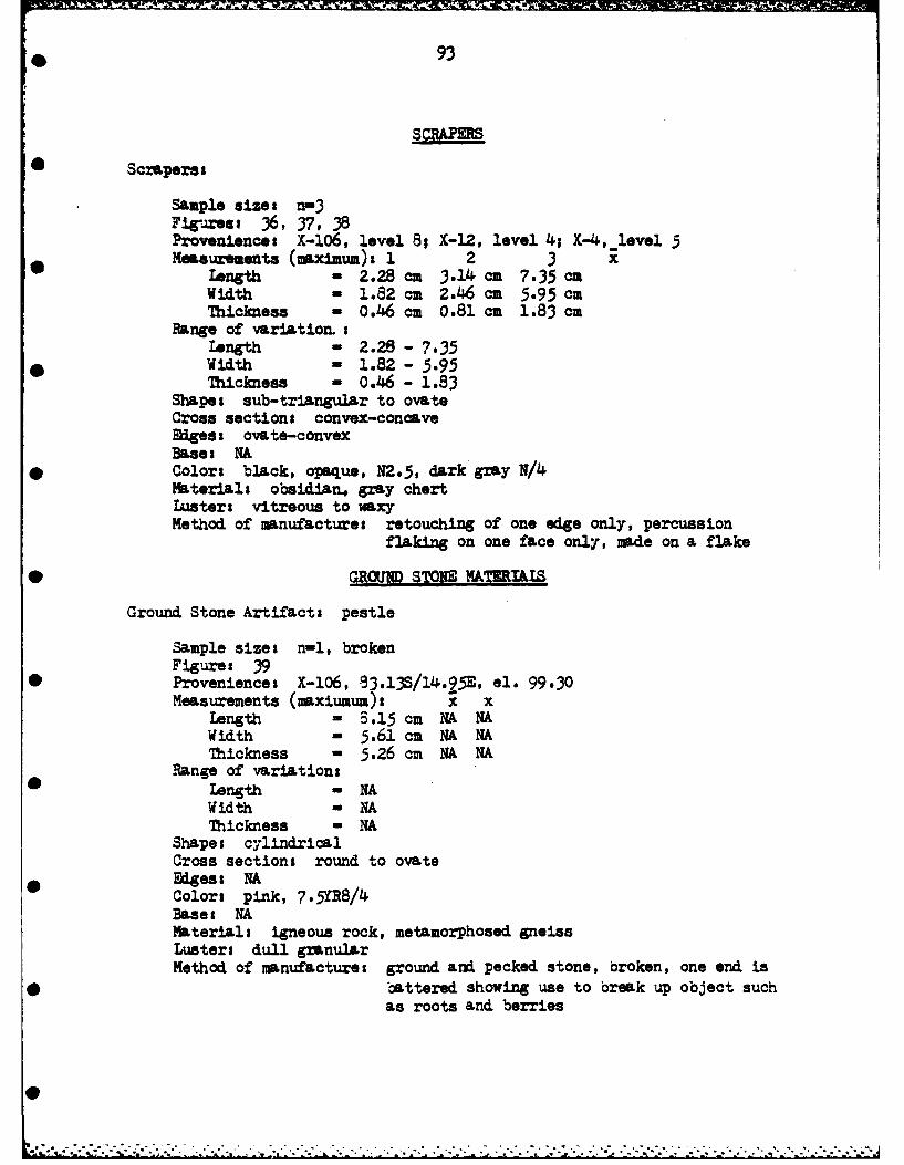
0 93
SCRAP=RS
* Sczaperst
Sample sizes n-3Firae 1 6, 37, 38Proveniences X-106, level 8; X-12, level 4; X-4, level 5Measurements (maximum). 1 2 3 x
Length - 2.28 cm 3.14 ca 7.35 caWidth - 1.82 cm 2.46 cam 5.95 camThickness 0.46 cam 0.81 cam 1.83 ca
Range of variation.-ILength - 2.28 - 7.35Width - 1.82 - 5.95Thickness - 0.46 - 1.83
Shapes sub-triangular to ovateCross sections convex-concavedgess ovate-convex
Bases NA* Colors black, opaque, N2.5, dark gray N/4
Materials obsidian, gray chertLusters vitreous to wxyMethod of manufactures retouching of one edge only, percussion
flaking on one face only, made on a flake
0 GROUNM STOIM FATEIALS
Ground Stone Artifacts pestle
Sample sizes n-i, brokenFigure: 39
0 Provenience: X-106, 93.13S/14.95E, el. 99.30Measurements (maxiumum)s X x
Length = 3.15 cm NA NAWidth - 5.61 cm NA NAThickness = 5.26 cm NA NA
Range of variationsLength - NAWidth = NAThickness = NA
Shapes cylindricalCross sections round to ovate
0 Miges: NAColors pink, 7.5YR8/4Bases NAMaterials igneous rock, metamorphosed gneissLusters dull granularMethod of manufactures ground and pecked stone, broken, one end is
* battered showing use to break up object suchas roots and berries

PART VI
SSn~MMARY AND RECOMMENDATIONS
Archaeological test excavations by Pavesic and Meatte have revealed
* extensive prehistoric occupation of the MUM locale which appear to date
from the late prehistoric period, ca. 850 to 1350 A.D. (Pavesic and
Meatte 1980:79) with cultural ties to the Northern Great Basin as opposed
0 to the Columbia Plateau (Pavesic and Meatte 1980:77). Pavesic and Meatte
tested the site area, isolating seven localities and recommending further
work be done in those areas to be impacted by future construction.
In an effort to avoid impacts to the cultural resources present at
the archaeological site, the Walla Walla District, USACE, redesigned the
proposed project so as to place the new facilities outside of the site
boundaries. In order to make certain that the resources would not be
destroyed or otherwise compromised, archaeological testing of the site
was suggested and carried out by EWU under the direction of Harvey S.
Rice, Principal Investigator, and Gordon A. Lothson, the Field Director.
The results of these investigations have been presented here with minimal
analysis. Detailed analysis was considered beyond the scope of work
outlined by LeRoy Allen, Archaeological Coordinator, Walla Walla District,
USACE.
It is the opinion of the writers of this study that the site areas
tested have been greatly affected by the activities of modern man and
that some additional but restricted work should be done. It is also our
opinion that the Integrity of Location provision of the National Register
criteria as stated in CFR 800, part 800.9 and 36 CFR 60, part 60.6, are
not applicable to Areas VII and VIII described herein. These two areas
94

93he ie sia ...at Yummalo ..a MOMe. but e
zsJA] additioeal data that would make aitional exctawtim worth the
moasy end time :Lvested, except in regard to the reservatim and roe.-
indations listed below:
The quality of significance in American history, architecture,* archaeology and culture Is present in districts, sites, buildings,
structures and objects of state and local Importance that possessIntearitZ of location. desoan, setting, mat..eals, wrks'hU,feelina and association . . . that have yielded, or ay be likelyto yield, Information Important In prehistory or history (36 CIR 60,part 60.6) [Emphasis added].
0Areas VII and VII are unlikely to yield Important archaeological data.
Area VI, situated near Riley Creek, however, has yielded and is likely
to yield additional significant archaeological data. For these reasons,0
we have suggested the following recomendations.
Recomndations
1. It is our feeling that the proposed site of the administrative
complex does not meet the criteria of the National Register of Historic
Places. The feature found by Pavesic and Meatte (1980:119) probably
represents an isolated activity area, the function of which has not been
clearly defined. We do not feel that any additional work need be done
as the area is greatly disturbed and the density of materials so low as
to be insignificant.
2. Area VI, on the other hand, contains significant quantities of
cultural debris that should be extensively tested at the Phase III level
of analysis if additional construction is planned in the area (Lothson
1979, 1980). How extensive this testing should be is dependent, of course,
on the amount of disturbance caused by y propp- . construction. This
area contains obvious cultural features i., Atu that could provide mean-
ingful data relevant to spatial analysis of the kind described by Clarke
0
£'t F ' . r - ..l . * J** , .•*- --

* 96
(1977). This area should be excavated if it is to be disturbed by con-
stmCtion activities.
* 3. The cold storage area (Cold Storage Area VIII) is also clear of
significant archaeological materials except for an extremely small portion
lying adjacent to an outcrop of rock southwest of the proposed raceways
* to be constructed at the UNFH site. If this area cannot be avoided by
construction activities, it could easily be cleared by those who do any
mitigation work at the site. The undisturbed area is very small indeed
• and would require only one or two days by a crew of six to eight persons
to extract an adequate sample. The remainder of the cold storage area
requires no additional work as it has been badly disturbed by earlier
construction activities. It is our feeling that no adverse effect will
result in the construction of the cold storage unit. The location of the
test pits containing archaeological materials are indicated in Fig. 26.
This report should not be considered to be permission to proceed
with this proj. .:. It contains professional opinions on cultural resources
that might be affected by the project. This report should be submitted to
the appropriate review agencies for their comments prior to the commence-
ment of any ground disturbing activities.
@

BIBLIOGRAHY
* Braidwood, Robert J.1975 Prehistoric men (eighth ed.). Scott, Foresman, Glenview,
Illinois.
Butler, B. Robert1968 A guide to understanding Idaho archaeology (second ed.,
*revised). Special Publication. Idaho State Museum, Pocatello,
Clarke, David I.-1977 Spatial archaeology. Academic, New York.
Code of Federal Regulations* 1966 36-CFR-800, part 800.9 and 36-cFR-60, part 60.6. Department
of Interior, National Park Service, Washington, D.C.
Coles, T.M., and E.S. Higgs1968 The archaeology of early man. Penguin Books, Haxmondsworth,
Middlesex, England.
Contract #DACW-81-C- 02261980 Walla Walla District, U.S. Army Corps of Engineers, Walla
Walla, Washington and Eastern Washington University, Cheney.
* n.d. Map furnished by LeRoy Allen, Archaeological Coordinator,Walla Walla District, U.S. Army Corps of Engineers, WallaWalla, Washington.
Crabtree, Don E.1972 An introduction to flintworkin . Pocatello, Idaho.
Daubenmire, Rexford1970 Steppe vegetation of Washington. Washington Agricultural
Experimental Station, Technical Bulletin 62. WashingtonState University, Pullman.
Franklin, Jerry F. and C.T. Dyrness1973 Natural vegetation of Oregon and Washington. USDA Forest
Service, General Technical Report PNW-8. U.S. Departmentof Agriculture, Portland, Oregon.
Hironaka, M. and M.A. Fosberg1979 Non forest habitat types of southern Idaho. Interim Report.
College of Forestry, Wildlife and Range Sciences. Forest,Wildlife and Range Experiment Station. University of Idaho,Moscow.
* Lothson, Gordon A. and William Gray1979 Phase II excavation and testing of the Rock Island Reservoir,
Washington 1977. Washington State University Progress Report81. Washington Archaeological Research Center, Pullman.
97C

98
Lothson, Gordon A., Thomas Gene Smith and David J. Johnson1980 Phase II excavation and testing of the Rock Island Dam
Reservoir Washington# A study in spatial analysis. ChelanCounty Public Utility District No. 1. District Resolution5632. Washington Archaeological Research Center, WashingtonState University, Pullman.
Morrison, R.B. and John C. Frye1965 Correlation of the middle and late quaternary successions of
the Lake lahontan, Lake Bonneville, Rocky Mountain (WasatchRange)s Southern Great Plains and Eastern Midwest Areas.Nevada Bureau of Mines Repit 9. University of Nevada, Reno.
Pavesic, Max G. and Daniel S. Meatte1980 Archaeological test excavations of the National Fish Hatchery
locality Hagerman Valley, Idaho. Archaeological Report 8.Boise State University, Boise, Idaho.
Soil Survey Staffn.d. Soil survey manual agricultural handbook 18 (revised).
Fifth draft manuscript copy uneditied 1975. USDA Soil Con-servation Service Section I.
Soil Taxonomy1975 U.S. Department of Agriculture Soils and Water Conservation
Service prepared by the Soils Conservation Research Group.
Webster, D.C., Victor R. Baker and Carl Gustafson1976 Channeled scablands of southeatern Washington& A road log
via Spokane-Coulee City-Vantage-Washtucna-Lewiston-Pullman.Field Guide 2. Department of Geology, Washington State Uni-versity, Pullman.
References cited in Pavesic and Meatte 1980.
Stearns, Harold T., Lynn Crandall and W.G. Steward1938 Geology and groundwater resources of the Snake River Plain
in southeastern Idaho. U.S. Geological Survey, Water-SupplyPapr 774. Washington.
Young F.O., Glen Trail and B.L. Young1929 Soil survey of the Gooding area, Idaho. Bureau of Chemistry
and Soils 10. U.S. Departaeht of Agriculture, ashington.

APPENDIX A
0 VEGETATION OF THE HAGERMAN~ LOCAIZ(After Franklin and Dyrness, 1973)
* Artemisia, tridentata-Agopyron spicatum Association
1. Artemisia tridentata (big sagebrush)2. A&ropyron spicatum (bluebunch wheatgrass)3. Poa sandbergii (Sandbergs bluegrass)4. Phl-ox diffusa (spreading lox)
*5. Aster scopulorum (crag aster)
6. Aster canescens (hoary aster)7. Chaenactis ougilasii (falseyarrow)8. Collinsia parviflora (litileflower collinsia)9. Phlox gracilis (pink annual phlox)
*10. Lappula redowskii (western stickseed)
U1. Gayophytum, ramosissimum (hairstem groundsmoke)
Artemisia rigida-Poa sandbergii Association
1. Artemisia rigida (stiff sagebrush)2.* Poa sandbergii (Sandbergs bluegrass)3. Bromus tectorum (cneatgrass brone)4. Festuca microstachys (Nuttall's bescue)5. Agropyron spicatum (bluebunch wheatgrass)
6. Sitanion hystrix (bottlebrush squirreltail)7. Mimulu6 nanus (dwarf monkeyf lower)8. Zigadenus paniculatus (foothill deathcamas)
Riparian Environmental Association.-
A whole series that is area specific, the major constituents of which
are Salix sp. (willow) and Typha latifolia (broad-leaved cattail).
99

APPENDIX B
FAUNAL RESOURCES OF THE NORTHERN GREAT BASIN(after Pavesic and Meatte, 1980)
Mammals* western canyon bat (Pipistrellus hesPerus)
Snake River Valley raccoon (Procyon lotor excelaus)little spotted skunk (Spiloxale =racilis saxatilis)Nevada long-eared desert fox (VulDes macrotis nevadensis)Nevada mantled ground squirrel (Spermarhilus lateralis)
* Great Basin chipmunk (Eutamias minimus scrutator)Townsend pooket gopher (Thomomys townsendii)Idaho pocket mouse Perognathus parvus idahoensis)Columbia kangaroo rat Dip 4 ordii. columbianus)short-tailed grasshopper mouse (Onychomus leucogaster brevicaudus)
* canyon mouse (Peromyscua crinitus c.)Nevada wood rat (Neotoma lepida nevadensis)desert black-tailed jack rabbit (Lepus californicus deserticola)muskrat (Ondatra zibethicus)yellow-bellied marmot (Marmota flaviventris)
* cottontail (Sylvilagus nuttallii)bobcat (Lynx rufus)chipmunks Eutamias minimusbadger (Taxidea taxus)coyote (Canis latrans
* weasels (Mustela erminea and [M.] frenata)mink (Mustela vison)otter (Lutra canadensis)mule deer (Odocoileus heminonus)pronghorn antelope (Antilocapra americana)
bison (Bison bison)
Birds
mallard [duck] (Anas platyrhynchos)Canada. goose (Branta canadensis)
0Fish
Chinook salmon (Oncorhynchus tshawytscha)steelhead trout (Salmo Rairdneri)
100
e

I"
APPENDIX C
0 SOIL DESCRIPTION OFTWE HAGERMAN NATIONAL FISH HATCHERY SITE
(after Pavesic and Meatte, 1980)
* Profile Description
Site lo-GG-176, Hagerman National Fish Hatchery
Profile of pit wall North 45/East end, Unit 5.
SEAh?]* 01 10-0 cm--Pasture grass root zone, under sprinkler irrigation;abrupt wavy boundary to
Al 0-32 cm--Brown (IoYR5/3, moist) silt loam with occasional verycoarse sand and granule gravel, well rounded; massive; soft,very friable, nonsticky, nonplastic, krotovena present with
• iron mottling (Dr. Yellow Brown), cultural debris, flakes, firecracked rock and charcoal; increasing pores near lower boundary;lower boundary marked by moisture content; clear wavy boundary to
All 32-52 cm--Dark yellowish brown (IOYR4/4, moist) silt loam withoccasional very coarse sand and granule gravel, well rounded;
* massive; soft, friable, nonsticky, nonplastic; iron staining-mottling from irrigation; few fine roots; few fine vesicularpores; cultural material present; lower boundary determined onthe increased number of pores and reduction of iron stainingiabrupt wavy boundary to
* Cl 52-100 cm--Yellowish brown (10YR5/4, moist) silt loam to loam;massive; soft, very friable, nonsticky, nonplastic; common finevesicular pores with carbonate coatings; few fine roots, occa-sional very coarse sand and granule gravel, well rounded, novisible arrangement; iron staining-mottling present, granules ofcarbonate near lower contact; very abrupt wavy boundary to
C2 100-depth not determined--Light gray (10YRT7/2, moist) loam;massive; very hard, extremely firm, strongly cemented, nonsticky,nonplastic; carbonate fills many fine to coarse pores, root andinsect channels; very fine tubular pores within 1 cm diameter
Ofilled channels and is pinkish in color; nodules or dendriticpieces of carbonate can be isolated from sediment, these arehard and brittle but easily broken in hand.
Terms in [] are based on new soil classification system (Soil Survey Staff n..d.).
101
p

A[