d p. l. - city of busselton · for the changes to the existing installation. ... commscope...
TRANSCRIPT
Deighton Pty. Ltd. ABN39 220 486 601 ACN 009 001 076
P.O. Box 81 NORTH DANDALUP WA 6207
Telephone: (08) 9530 1550 Email: [email protected]
20th November, 2015.
Our Ref: RTP
The Chief Executive Officer, City of BusseIton, Locked Bag 1, BUSSELTON WA 6280
Dear Sirs/Madam,
Development/Planning Application for the Regional Telecommunications Project Proposed Mobile Phone Base Station
Lot 1 on D73788Abbev Farms Road, Wilyabrup WA 6285 (GPS -33.72336 115.04331)
Telstra is working on a State Government funded emergency services and mobile telephone communications project and is proposing a site at the above location.
This chosen site will be built under the Regional Telecommunications Project and will be funded by the State Government's Royalties for Regions Program which is administered by the Western Australian Department of Commerce with the assistance of the Department of Regional Development and Lands — Telstra have been contracted to undertake construction of this project.
Deighton Pty Ltd, act on behalf of Aurecon in regard to the above matter. Aurecon have been instructed by their client Telstra Corporation Limited to prepare and lodge a proposal for the changes to the existing installation.
Following intensive investigations between Government Emergency Services Agencies and Telstra utilizing radio frequency engineers, property and planning consultants and general engineering expertise Telstra has identified a location for the construction of a site under the above project.
As part of the site identification process we identified some potential sites early in the investigation and held discussions with the respective landowners. We identified two sites in Carpenter Road (Lot 20 and Lot 51) and we approached both landowners however neither was prepared to consider a structure on the property.
We also held discussions with the Manager of Cape Lodge in Caves Road however that site, in our opinion, was unable to achieve the setback from Caves Road required in Council's Planning Policy.
DA15/0657
...2/- 16.11.15
We also identified a number of sites at Clareault Winery and held detailed discussions with the Management who in turn held discussions with Mr John Streiker in New York who is the landowner however, after several months of discussion they were unprepared to make a site available on their landholding.
Given the sensitive nature of the area in general we determined that, in order to meet Council's requirement of 500m back from Caves Road, we needed to locate the site on a large landholding to ensure appropriate separation from the proposed infrastructure to existing housing in the area. Therefore we approached Mr Barry House MP and he agreed to the location of the infrastructure at the rear of his property Lot 1 176 Abbey's Farm Road and a site visit with Mr House determined that a disturbed area on the property where gravel had been removed in the past would be the most suitable location and provide the best separation to adjoining neighbours.
We believe that the selected location, being more than 500m back from Caves Road and visually protected by remnant vegetation provides the most unobtrusive location for the structure given that the Government requirements for Emergency Services use is that the
, structure be 60m high.
The proposal is to install, at the above location, a 60m guyed mast, this structure type has been selected to minimise visual impact in the skyline as a free standing tower of this size would be more imposing on the surroundings. The structure is to accommodate three (3) Commscope RVVPX310B2 panel antennas at the 58.60 level and three RRU's located as close to the rear of the antennas as possible together with an equipment room located at the base of the structure.
Additionally you will note that the upper area of the structure also contains future reservations for the Emergency Services Organisations for potential future requirements. All proposed work as shown on the attached drawings W107847 S3 Issue 1, S i and S1-1 Issue .1
This Application has been prepared having regard for the Planning Laws and Regulations encompassed within Town Planning Scheme administered by Council that apply to the proposed site.
As a Licensed Carrier under the Commonwealth Telecommunications Act 1997, Telstra is also obliged to comply with the Industry Code on the Deployment of Radiocommunications
, Infrastructure (the Code) in relation to this proposal. Sections 5.1 and 5.2 of the Code are relevant to the preparation of this Development/Planning Application.
Selection of the site has been made utilising the policy provisions encompassed within the WAPC Statement of Planning Policy No 5.2.
With regard to Section 5.3 of the above policy we advise the following:
• Proposed Materials and Colour — It is proposed that the antennas be installed utilising the colour as supplied by the manufacturer.
• Fencing — Fencing as shown on attached drawing.
DA15/0657

...3/- 16.11.15
Telstra and EME
• Telstra places high importance on effective and responsible management of EME issues.
• Telstra acknowledges some people are genuinely concerned about possible health effects from the EME generated by radio frequency technology and is committed to addressing these concerns responsibly.
• Telstra's responsible approach to EME is demonstrated through compliance with relevant radio frequency standards and comprehensive policies and procedures to protect the health and safety of the community and employees.
• Telstra operates responsibly in the design, operation and management of mobile base stations in order to minimise community impact and comply with the industry code of practice (ACIF Code) for base station deployment and operation.
• Telstra also maintains a comprehensive EME research program, monitors international research developments and provides assistance to other research institutions on Australian research into EME. This enables Telstra to have accurate and substantiated scientific information to guide its actions.
EME Safety Standard
In Australia, the EME safety standard is set by ARPANSA and regulated by the Australian Communications Authority (ACA) — the independent regulator of the nation's telecommunications industry.
It is based on careful analysis of the scientific literature (both thermal and non-thermal effects) and is designed to offer protection against identified health effects of EME with a large in-built safety margin. The standard covers EME emissions from all antennas on a single tower, or group of towers.
Compliance with all applicable EME standards is part of Telstra's responsible approach to EME and mobile phone technology.
Further information on EME can be obtained through the ARPANSA Website www.arpansa.gov.au
A copy of the ACMA EME fact sheet is available at wwvv.acmasiov.au/consumer info/fact sheets/consumer fact sheets/fsc91.htm and a copy of the ACMA EME and Health Video is available at www.acma.gov.au/csds compliance/electromagnetic radiation/emr videos/index.htm
Telstra confirms that it has applied the Precautionary Approach in selecting the proposed site at the above location in accordance with Section 5.1 of the Code. Further, that the Precautionary Approach has also been applied to the design of this proposed monopole installation in accordance with Section 5.2 of the Code.
DA15/0657
...4/- 16.11.15
We have also enclosed a signed Development Application Form together with our cheque for $416.00.
Should you wish to discuss this proposal please do not hesitate to contact the undersigned.
, Yours faithfully,
Steve Bruce, DIRECTOR
DEIGHTON PTY LTD
Enclosures
DA15/0657
geistra Environmental EME Report
Lot 1 D73786 Abbey Farms Road, YALLINGUP WA 6282
This report provides a summary of Calculated RF EME Levels around the wireless base station
Date 6/11/2015 Introduction
RFNSA Site No. 6282007
The purpose of this report is to provide calculations of EME levels from the existing facilities at the site and any proposed additional facilities.
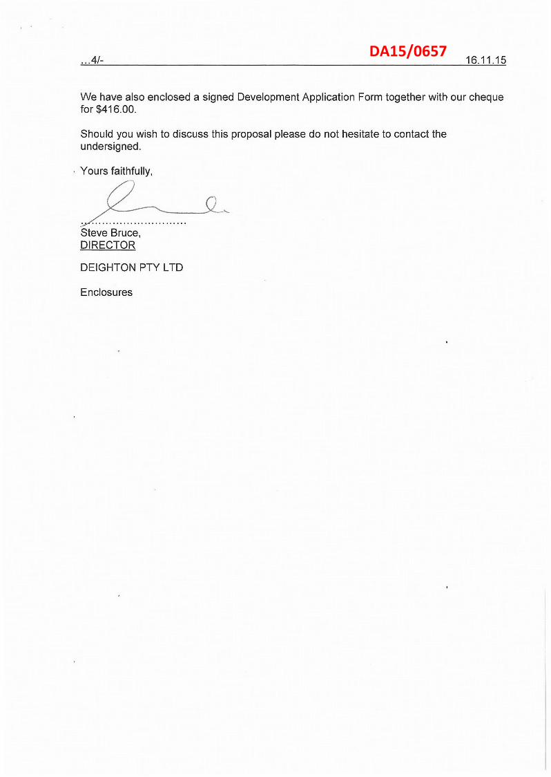
This report provides a summary of levels of radiofrequency (RF) electromagnetic energy (EME) around the wireless base station at Lot 1 D73786 Abbey Farms Road, YALLINGUP WA 6282 . These levels have been calculated by Telstra using methodology developed by the Australian Radiation Protection and Nuclear Safety Agency (ARPANSA).
The maximum EME level calculated for the proposed systems at this site is 0.022% of the public exposure limit.
The ARPANSA Standard ARPANSA, an Australian Government agency in the Health and Ageing portfolio, has established a Radiation Protection Standard specifying limits for general public exposure to RF transmissions at frequencies used by wireless base stations. The Australian Communications and Media Authority (ACMA) mandates the exposure limits of the ARPANSA Standard.
How the EME is calculated in this report The procedure used for these calculations is documented in the ARPANSA Technical Report "Radio Frequency EME Exposure Levels - Prediction Methodologies" which is available at http://www.arpansa.gov.au.
RF EME values are calculated at 1.5m above ground at various distances from the base station, assuming level ground.
The estimate is based on worst-case scenario, including: • wireless base station transmitters for mobile and broadband data operating at maximum power • simultaneous telephone calls and data transmission • an unobstructed line of sight view to the antennas.
In practice, exposures are usually lower because: • the presence of buildings, trees and other features of the environment reduces signal strength • the base station automatically adjusts transmit power to the minimum required.
Maximum EME levels are estimated in 360° circular bands out to 500m from the base station.
These levels are cumulative and take into account emissions from all mobile phone antennas at this site. The EME levels are presented in three different units:
• volts per metre (Vim) — the electric field component of the RF wave
• milliwatts per square metre (mW/m2) — the power density (or rate of flow of RF energy per unit area)
• percentage (%) of the ARPANSA Standard public exposure limit (the public exposure limit = 100%).
Results The maximum EME level calculated for the proposed systems at this site is 0.61 Vim; equivalent to 0.99 mW/m2 or 0.022% of the public exposure limit.
Environmental EME report (v11.3, Feb 2014) Produced with RF-Map 2.0 (Build 1.18) NAD (v1.0.60052.26331)
DA15/0657

Radio Systems at the Site There are currently no existing radio systems for this site.
It is proposed that this base station will have equipment for transmitting the following services:
Carrier Radio Systems
Telstra WCDMA850 (proposed)
Calculated EME Levels This table provides calculations of RF EME at different distances from the base station for emissions from existing equipment alone and for emissions from existing equipment and proposed equipment combined.
Distance from the antennas at Lot 1 D73786 Abbey
Farms Road, in 3600 circular bands ,
Maximum Cumulative EME Level — All carriers at this site
Existing Equipment Proposed Equipment
Electric Field V/m
Power Density mW/m2
% ARPANSA exposure limits
Electric Field V/m
Power Density mW/m2
% ARPANSA exposure limits
Om to 50m 50m to 100m 100nn to 200m 200m to 300m 300m to 400m 400m to 500m
0.2 0.2 0.22 0.55 0.61 0.6
0.11 0.1 0.12 0.8 0.99 0.97
0.0024% 0.0023% 0.0027% 0.018% 0.022% 0.021%
Maximum EME level 0.61 0.99 0.022
361.11 m from the antennas at Lot 1 D73786 Abbey Farms Road,
Calculated EME levels at other areas of interest This table contains calculations of the maximum EME levels at selected areas of interest that have been identified through the consultation requirements of the Communications Alliance Ltd Deployment Code C564:2011 or via any other means. The calculations are performed over the indicated height range and include all existing and any proposed radio systems for this site.
Additional Locations Height / Scan
relative to location ground level
Maximum Cumulative EME Level All Carriers at this site
Existing and Proposed Equipment Electric Field
V/m Power Density
mW/m2 % of ARPANSA exposure limits
No locations identified
Environmental EME report (v11.3, Feb 2014) Produced with RF-Map 2.0 (Build 1.18) NAD (v1.0.60052.26331)
DA15/0657

Information
telecommunications
RF EME Exposure Standard The calculated EME levels in this report have been expressed as percentages of the ARPANSA RF Standard and this table show g the actual RF EME limits used for the frequency bands available. At frequencies below 2000 MHz the limits vary across the band and the limit has been determined at the Assessment Frequency indicated. The four exposure limit figures quoted are equivalent values expressed in different units — volts per metre (V/m), watts per square metre (W/m2), microwatts per square centimetre (pW/cm2) and milliwatts per square metre (mW/m2). Note: 1 W/m2= 100 pW/cm2= 1000 mW/m2.
Radio Systems Frequency Band AssessmentFrequency ARPANSA Exposure Limit (100% of Standard)
LTE 700 758 – 803 MHz 750 MHz 37.6 V/m = 3.75 W/m2 = 375 pW/cm2 = 3750 mW/m2
WCDMA850 870 – 890 MHz 900 MHz 41.1 V/m = 4.50 W/m2 = 450 pW/cm2 = 4500 nnW/m2
GSM900, LTE900, WCDMA900 935 – 960 MHz 900 MHz 41.1 V/m = 4.50 W/m2 = 450 pW/cm2 = 4500 mW/m2
GSM1800, LTE1800 1805 – 1880 MHz 1800 MHz 58.1 V/m = 9.00 W/m2 = 900 pW/cnn2 = 9000 mW/m2
LTE2100, WCDMA2100 2110 – 2170 MHz 2100 MHz 61.4 V/m = 10.00 W/m2 = 1000 pW/cm2 = 10000 mW/m2
LTE2300 2302 – 2400 MHz 2300 MHz 61.4 V/m = 10.00 W/m2 = 1000 pW/cm2 = 10000 mW/m2
LTE2600 2620 – 2690 MHz 2600 MHz 61.4 V/m = 10.00 W/m2 = 1000 pW/cm2 = 10000 mW/m2
LTE3500 3425 – 3575 MHz 3500 MHz 61.4 V/m = 10.00 W/m2 = 1000 pW/cm2 = 10000 mW/nn2
Further Information The Australian Radiation Protection and Nuclear under the Health and Ageing portfolio. ARPANSA and the environment, from the harmful effects of radiation
about RF EME can be accessed at the ARPANSA • Further explanation of this report in the document • The procedure used for the calculations in this
Exposure Levels - Prediction Methodologies" • the current RF EME exposure standard
Australian Radiation Protection and Nuclear Exposure Levels to Radiofrequency Fields — Yallambie Australia. [Printed version: ISBN 0-642-79400-6 ISSN
The Australian Communications and Media Authority (ACMA) and online content. Information on
The Communications Alliance Ltd Industry Code C564:2011 Alliance Ltd website, http://commsalliance.com.au
.
Safety Agency (ARPANSA) is a Federal Government agency incorporated is charged with responsibility for protecting the health and safety of people,
(ionising and non-ionising). website, http://www.arpansa.qov.au, including:
"Understanding report is documented
Safety Agency (ARPANSA), 3 kHz to 300 GHz',
1445-9760] [Web
is responsible EME is available
'Mobile Phone
present at this
the ARPANSA Environmental EME Report" in the ARPANSA Technical Report; "Radio Frequency EME
2002, 'Radiation Protection Standard: Maximum Radiation Protection Series Publication No. 3, ARPANSA,
version: ISBN 0-642-79402-2 ISSN 1445-9760] . for the regulation of broadcasting, radiocommunications,
at htto://ernracma.qov.au
Base Station Deployment' is available from the Communications
site and the most recent version of this document are available Contact details for the Carriers (mobile online at the Radio Frequency National
Environmental EME report (v11.3, Feb 2014)
phone companies) Site Archive, http://www.rfnsa.com.au.
Produced with RF-Map 2.0 (Build 1.18) NAD (v1.0.60052.26331)
DA15/0657

Remote Radio Unit Description RRUW
3 Technical Data
This section describes the physical characteristics, environmental data, and the power supply of the RBS.
3,1 Dimensions
Table 1 lists the technical data for the RRUW.
Table 1 Technical Data RRUW
Description !Maximum nominal output power
!Number of carriers
!Frequency 1
'Dimensions without Solar Shield !Height 'Width 'Depth ;Dimensions with Solar Shield 'Height 'Width
,Value !Without license key: 20 W With 40 W license k e y ' : 40 W With all license keys (1): 60 W One carrier: without licence key 'Up to four carriers: with license key 11,920 to 1,980 MHz uplink
2,110 to 2,170 MHz downlink
and 1 11,850 to 1,910 MHz uplink
11,930 to 1,990 MHz downlink
!Band 2 :824 to 849 MHz uplink
869 to 894 MHz downlink
!Band 5 1,427.9 to 1,437.9 MHz uplink
1,475.9 to 1,485.9 MHz downlink 1 iBand 11
600 mm 1350 mm 1112 mm
636 mm 383 mm
DA15/0657
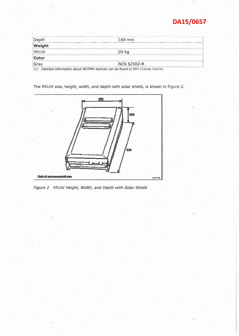
1Depth {Weight
RRUW 20 kg .Color Gray NCS S2502-R (1) Detailed information about WCDMA licences can be found in PBS License Control.
169 mm
20 kg
NCS S2502-R
The RRUW size, height, width, and depth with solar shield, is shown in Figure 2.
Figure 2 RRUW Height, Width, a n d Depth with Solar Shield
DA15/0657

PRODUCT SPECIFICATIONS PRELINt RVVPX310B2
NARY
698-960 / 2 x 1710-2690 MHz 3 Band Remote Tilt Panel Antenna, Internal Bias T
Frequency Range
Gain • 16 dBi 16.5 dBi 16.8 dBi 16.5 dBi 17 dBi 18 dBi Return Loss > 15dB > 14dB Polarization Dual Slant *45° Horizontal Beamwidth 63° 600 600 650 620 60° Vertical Beamwidth 9.8° 8.8° 80 8.2° 7.2° 5.8° Electical Downtilt 0° - 100 continuous, bands independently adjustable Upper Sidelobe Level < -18 dB < -18 clB typical up to 20' above horizon
Front to Back Ratio > 25 dB Port Isolation - same band > 25 dB - between bands > 30 dB Power Rating 300W 250W Intermodulation < -150dBc (2 x 43 dBm) Impedance 50 ohm Lightning Protection ' DC grounded Connector Type 6 x 7- 16 DIN female RET Type Internal motor and manual override, Internal Bias-T from Port 3 (Band 2) AISG Connector 8 pin male and female IN/OUT pair. Bands cascaded SRET
Band 1 698-960 MHz
Band 2 & 3 1710-2690 MHz
698-790 790-890 890-960 1710-1920 1920-2170 2300-2690
16 dBi 16.5 dBi 16.8 dBi 16.5 dBi 17 dBi 18 dBi > 15dB > 14dB
Antenna Dimensions 2533 x 353 x 209 mm Packed Dimensions 2720 x 436 x 320 mm Weight 32 kg Radome Material UV Stabilised ASA
Humidity 95% RH @ +30°C Lateral Loading (Front) 1.32 kN @ 160 km/h Lateral Loading (Rear) 1.12 kN oft 160 km/h Rain 140 mm per hour Rated Wind Velocity 200 km/h Temperature -40°C to +70°C
7.7!c,,,jf\1!'N(.-"; OPT.
F-042-GL-E T-029-GL-E
Azimuth (Low Band)
Azimuth (High Band)
Last Modified: 30/10/2012 W: www.argusantennas.com E: infoargusantennas.com Argus Technologies is continually improving products. Specifications may change at any time without notice.
Fixed Clamps Adjustable Clamps
Elevation (Low Band)
Elevation (High Band)
DA15/0657

2 a / ■ 4 5 6
A TN PROPOSED TELSTRA FIBRE — EXISTING POWER POLE
ROUTE TO EXISTING FAR /
PROPERTY BOUNDARY (TYP)
INSTALL GATE HERE IN NEW STOCK FENCING. REFER NOTE 4
LOT 20 LOT 7
• - 144Z‘S.-}-A•pqr.„,
• . " LOT 8 '
LOT 2 LOT 40
-11
LOT 17
LOT 11
LOT 4095
OVERALL SITE LAYOUT NOT TO SCALE
NOTES: 1. FOR EME SIGNS NOTATED kiA REFER TO 005486 FOR DETAILS. 2. THIS DRAWING SET IS A PRELIMINARY DRAWING ONLY AND IS ISSUED FOR COMMENT, IT IS NOT
A DETAILED SURVEY / STRUCTURAL DRAWING AND THEREFORE COULD BE SUBJECT TO CHANGE. 3, DRAWING TO BE READ IN CONJUNCTION WITH SHEETS S1-1 AND S3. 4. NEW STOCK FENCE TO BE INSTALLED AS SHOWN, TO FENCE OFF ACCESS TRACK FROM REST OF FARM.
SURVEYOR WILL MEET WITH LANDOWNER ON SITE TO REFINE AND PLOT EXACT ROUTE AT DETAILED DESIGN STAGE.
DO NOT SCALE
PROPERTY DESCRIPTION LOT 1 ON DIAGRAM 73786 ABBEYS FARM ROAD YALLINGUP WA. 6282 CITY OF BUSSELTON
SITE STRUCTURE CO-ORDINATES (GDA94) GPS READING ACCURACY: ±10m
CENTRE OF GUYED MAST
k7,3
RFNSA SITE No. 6282007
Copyright 0 Whereie Registered Trademark of Sensis Pty Ltd.
EXISTING ACCESS GATE
PROPOSED ACCESS ROUTE, REFER NOTE 4. SOME VEGETATION TRIMMING MAY BE REQUIRED TO ALLOW CONSTRUCTION ACCESS
NEW STOCK FENCING ENDS AT THIS ACCESS GATE. INSTALL GATE WHERE NEW FENCE MEETS EXISTING. REFER NOTE 4
EXISTING ACCESS GATE AND STOCK FENCE
PROPOSED TELSTRA FACILITY LOCATED WITHIN EXISTING GRAVEL PIT. REFER TO ELARGEMENT AND SHEET 51-1 FOR FURTHER DETAILS
PROPOSED TELSTRA U/G FIBRE ROUTE. FINAL ROUTE TO BE VERIFIED IN SITE SURVEY
PROPOSED TELSTRA U/G POWER ROUTE. FINAL ROUTE TO BE VERIFIED IN SITE SURVEY
INDICATES 500m RADIUS CLEARANCE FROM CAVES ROAD, TO MEET COUNCIL SETBACK REQUIREMENTS
LOCALITY PLAN `toc,r`lio,i, NOT TO SCALE
2
,EioN TIVA GE G
IS—SY Or—RITEFi DRAWN CHM AMENDMENT EXAM APPD DATE MIAMI23 CI
LATITUDE
LONGITUDE
2
-33.72336° (GDA94) burecon M e l e e , 4 6 9 6 4 4 P e Ltd ABH 99 054 10H73 Ieve15. T41961:994. 981 6 6149 PIO 053 H e 99 .1 . H I S F . H r r i t e l l 8 4145 SOX M e 4 4 , evs9494 6 0 0 A..69614 F e e t H4,9966,64,64.66619,9 6641
115.04331° (GDA94) p e w 4666.4.ccnewe9,6.961H44%41190149911 64,66 4/44.6696946.44.9 Hmemeateem94111.46611.1160
tem !or m u , 6-044.44.6eai lealeoe reeke. I. m g 6.1.19164/H6149169.101.610,494 9 a v e l k 111161741,164199.
BGW RC PRELIMINARY SP30049814W019A BGW MS 10,11.15 1
PRELIMINARY
MOBILE NETWORK SITE 295671 WILYABRUP
SITE LOCALITY AND ACCESS PLAN LOT 1 ON D73786 ABBEYS FARM ROAD
DWG NO. CYelstra Corporetion Limited ANN 33 051 775 556 All rights reserved, W107847 SOT Si
NO INDEX 3 \ / 4 5 6
DA15/0657
2 I 3 4 5 I_6
A
DO NOT SCALE
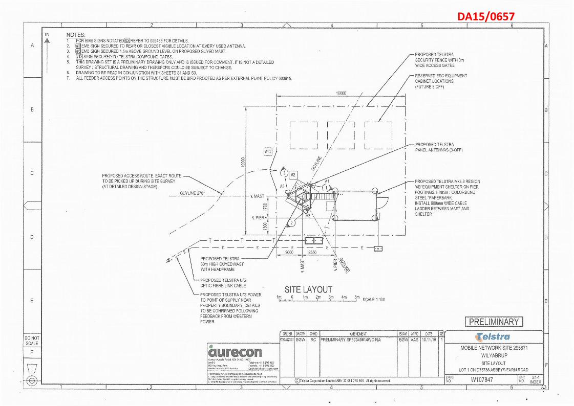
TN NOTES: 1. FOR EME SIGNS NOTATED a REFER 10 005486 FOR DETAILS. 2. rI EME SIGN SECURED TO REAR OR CLOSEST VISIBLE LOCATION AT EVERY USED ANTENNA. 3. 125 EME SIGN SECURED 1,5m ABOVE GROUND LEVEL ON PROPOSED GUYED MAST. 4, ( j a SIGN SECURED TO TELSTRA COMPOUND GATES. 5. THIS DRAWING SET IS A PRELIMINARY DRAWING ONLY AND IS ISSUED FOR COMMENT. IT IS NOT A DETAILED
SURVEY / STRUCTURAL DRAWING AND THEREFORE COULD BE SUBJECT TO CHANGE. 6. DRAWING TO BE READ IN CONJUNCTION WITH SHEETS S1 AND S3. 7. ALL FEEDER ACCESS POINTS ON THE STRUCTURE MUST BE BIRD PROOFED AS PER EXTERNAL PLANT POLICY 003615.
PROPOSED ACCESS ROUTE. EXACT ROUTE TO BE PICKED UP DURING SITE SURVEY (AT DETAILED DESIGN STAGE).
GUYLINE 270°
\ PROPOSED TELSTRA
I#131
c. MAST
10000 /
I r"
/
L _ J L
A3
#2
/ •.J
, Al
A3 \ ; : i 4 0 .1 igh gli.-..111106.1111r1111111111(
lbS'I'41,1F 114; Ap)... .. 1 PIER
— E — — — E —
6001 HIGH GUYED MAST WITH HEADFRAME
PROPOSED TELSTRA U/G OPTIC FIBRE LINK CABLE
PROPOSED TELSTRA U/G POWER TO POINT OF SUPPLY NEAR. PROPERTY BOUNDARY, DETAILS TO BE CONFIRMED FOLLOWING FEEDBACK FROM WESTERN POWER
SITE LAYOUT
c i ‘ 06, L_L-1
—E
lm 0 lm 2m 3m 4m 5m SCALE 1:100
(ORDER I DRAWN CHKD I AMENDMENT
PRELIMINARY
PROPOSED TELSTRA SECURITY FENCE WITH 3m WIDE ACCESS GATES
RESERVED ESO EQUIPMENT CABINET LOCATIONS (FUTURE 3 OFF)
PROPOSED TELSTRA PANEL ANTENNAS (3-OFF)
PROPOSED TELSTRA Mk3.3 REGION 'AB EQUIPMENT SHELTER ON PIER FOOTINGS, FINISH : COLORBOND STEEL "PAPERBARK. INSTALL 600mm WIDE CABLE LADDER BETWEEN MAST AND SHELTER
EXAM APO I DATE ISSY
NO6423.011 BOW I RC 'PRELIMINARY SP30049814W019A I BGW1 M S 110.11.15 1 1
aurecon ' , m a n 0+56565%6 Lid eau 59 D a i d , VI Lead 5 1516pliont .81 5 01419888 863 die, s h e . P . f w a d * . dill 6 6,15 5520 Vitsiern AdLuddia 6885 Ptigiaka 86168 [email protected]
5et9305id3 Aisedddidzidddsondoki 6816 ddapti 565 51 656,556585m 556 . “117 .5 , el.66,5686.81rediodi55,56
tlidin idt acdidocy .5-658 Vie 6 , 5 1 , 5 . 6 copy remand 658.1.5..656r866,0665V8any imidpede d m . . 8 id vrt8.59 6,545ton
MOBILE NETWORK SITE 295671 WILYABRUP SITE LAYOUT
LOT 1 ON D73786 ABBEYS FARM ROAD
elstra Corporation Limited ABN 33 051 775 556 All rights reserved, DWG NO. W107847 SOT
NO. INDEX 4 6 3
DA15/0657

2 3 4 5 6
A
<
DO NOT SCALE
TELSTRA RESERVATION AREA 7
INSTALL TELSTRA EME SIGNU BEHIND ALL NEW PANEL
ANTENNAS
PROPOSED TELSTRA PANEL ANTENNAS ON HEADFRAME WITH
TMAs MOUNTED BEHIND
• El. 60.00m TOP OF MAST
• El. 58.60m C/L PROPOSED TELSTRA PANEL ANTENNA (3 OFF)
• E.L. 56.6m CIL PROPOSED TELSTRA RRUS (3 OFF)
• El. 54.00m EXTENT OF ESO RESERVED AREA
El, 48.00m EXTENT OF ESO RESERVED AREA
PROPOSED GUYLINE (rep)
PROPOSED TELSTRA 60m 750mm / FACE CYCLONIC GUYED MAST
TELSTRA ANTENNA CONFIGURATION TABLE ANTENNA
No ANTENNA TYPE AND SIZEHxWxD
ANTENNA STATUS
ANTENNA HEIGHT
C/L A.G.L.
ANTENNA BEARING
(°T) SECTOR NO, AND SYSTEM
Al COMMSCOPE RVVPX31002 2533 x 353 x 209 INSTALL 513.60m 100° Si: WCDMA850
Sl: WCDMA850
A2 COMMSCOPE RVVPX31082 2533 x 353 x 209 INSTALL 58.60m 230° S2: WCDMA850
S2: WCDMA850
A3 COMMSCOPE RVVPX310B2 2533 x 353 x 209 INSTALL 58.60m 350° 33: WCDMA850
S3: WCDMA850
A
NOTES: 1. FOR EME SIGNS NOTATED REFER TO 005486 FOR DETAILS. 2. 71-2- EME SIGN SECURED TO REAR OR CLOSEST VISIBLE LOCATION AT EVERY USED ANTENNA, 3. #6 EME SIGN SECURED 1.5m ABOVE GROUND LEVEL ON PROPOSED GUYED MAST. 4. OE SIGN SECURED TO TELSTRA COMPOUND GATES. 5. THIS DRAWING SET IS A PRELIMINARY DRAWING ONLY AND IS ISSUED FOR COMMENT. IT IS NOT A DETAILED
SURVEY / STRUCTURAL DRAWING AND THEREFORE COULD BE SUBJECT TO CHANGE. 6. DRAWING TO BE READ IN CONJUNCTION WITH SHEETS Si AND S3. 7. ALL FEEDER ACCESS POINTS ON THE STRUCTURE MUST BE BIRD PROOFED AS PER EXTERNAL PLANT POLICY 003615.
PROPOSED TELSTRA Mk3.3 REGION 'AB' EQUIPMENT SHELTER ON PIER FOOTINGS. 600mm WIDE ELEVATED CABLE LADDER TO RUN FROM SHELTER TO MAST
PROPOSED TELSTRA SECURITY FENCE WITH 3m WIDE ACCESS GATES
INSTALL TELSTRA — EME SIGN #7611.5m AGL E.L. 0.00m
GROUND LEVEL
SOUTH ELEVATION 2,5m 0 5m
.1 I I 101m 1215m SCALE 1:250
PRELIMINARY Gni—a DRAWN CHKD AMENDMENT EXAM APPD DATE FSY WA08423.01 BOW RC PRELIMINARY SP30049814W019A BOW AAS 10.11.15 1
1_1
MOBILE NETWORK SITE 295671 WILYABRUP
SITE ELEVATION LOT 1 ON D73786 ABBEYS FARM ROAD
(Testa Carporetian Limited ANN 33 051 775 556 All rights reserved. DWG NO. W107847 SHT S3
NO. INDEX 1 2 3 4 1 6 A 3 -I
DA15/0657