cutler-hammer i.b. 29c891b - eatonpub/@electrical/documents/conten… · cutler-hammer instructions...
TRANSCRIPT

P
O
W
E
R
Q
U
A
L
I
T
Y
I.B. 29C891B
Effective 11/98 Supersedes I.B. 29C891A dated October 1996
Cutler-Hammer
Instructions for Operation and Maintenance of Digitrip OPTIM Trip Units
P R O T E C T I O N A N D C O O R D I N A T I O N
C O M M U N I C A T I O N S S Y S T E M S
E
N
E
R
G
Y
M
O
N
I
T
O
R
I
N
G
DSII/DSLII Power Circuit Breakers
SPB Systems Pow-R Circuit Breakers
Series C K, L, N and R Molded Case Circuit Breakers

I.B. 29C891B Page iii
Effective 11/98
All possible contingencies which may arise during installation, operation or maintenance, and all details andvariations of this equipment do not purport to be covered by these instructions. If further information isdesired by purchaser regarding his particular installation, operation or maintenance of particular equipment,contact a Cutler-Hammer representative.
WARRANTY AND LIABILITY INFORMATION
NO WARRANTIES, EXPRESSED OR IMPLIED, INCLUDING WARRANTIES OF FITNESS FOR A PARTICULARPURPOSE OF MERCHANTABILITY, OR WARRANTIES ARISING FROM COURSE OF DEALING OR USAGE OFTRADE, ARE MADE REGARDING THE INFORMATION, RECOMMENDATIONS AND DESCRIPTIONS CON-TAINED HEREIN. In no event will Cutler-Hammer be responsible to the purchaser or user in contract, in tort (includ-ing negligence), strict liability or otherwise for any special, indirect, incidental or consequential damage or loss what-soever, including but not limited to damage or loss of use of equipment, plant or power system, cost of capital, loss ofpower, additional expenses in the use of existing power facilities, or claims against the purchaser or user by its cus-tomers resulting from the use of the information and descriptions contained herein.

I.B. 29C891BPage iv
Effective 11/98
TABLE OF CONTENTS
PageSECTION 1: INTRODUCTION
1-1 Common Terms...................................................................................................................................................11-2 Preliminary Comments and Safety Precautions..................................................................................................1
1-2.1 Safety Precautions .................................................................................................................................11-3 Product Overview ................................................................................................................................................21-4 Features and Functions.......................................................................................................................................5
1-4.1 Common Features of Digitrip OPTIM 750 and 1050 Trip Units..............................................................51-4.2 Additional Features of Digitrip OPTIM 1050 Trip Units ..........................................................................7
SECTION 2: HARDWARE DESCRIPTION AND EQUIPMENT INTERFACES
2-1 General ...............................................................................................................................................................82-2 General Trip Unit Details .....................................................................................................................................8
2-2.1 Trip Unit Configuration ...........................................................................................................................82-3 Trip Unit Packages ..............................................................................................................................................82-4 Series C K, L-Frame and N-Frame OPTIM Trip Units.........................................................................................9
2-4.1 K, L-Frame and N-Frame OPTIM Trip Unit Displays..............................................................................92-5 Series C R-Frame, SPB and DSII/DSLII OPTIM Trip Units ..............................................................................11
2-5.1 R-Frame, SPB and DSII/DSLII OPTIM Trip Unit Displays ...................................................................122-6 OPTIM Trip Unit Rating Plug.............................................................................................................................142-7 External OPTIM Trip Unit Accessories..............................................................................................................152-8 Specification and Protective Range Summaries ...............................................................................................15
SECTION 3: OPERATION AND FUNCTIONALITY
3-1 General .............................................................................................................................................................203-2 Protection and Coordination..............................................................................................................................20
3-2.1 Over-Temperature Trip.........................................................................................................................203-2.2 Characteristic Curve Review ................................................................................................................203-2.3 Protection and Curve Shaping Features ..............................................................................................253-2.4 Long Delay Protection ..........................................................................................................................263-2.5 Short Delay Protection .........................................................................................................................283-2.6 Instantaneous Protection......................................................................................................................303-2.7 Ground Fault Protection .......................................................................................................................313-2.8 Time-Current Curves............................................................................................................................33
3-3 System Monitoring.............................................................................................................................................333-3.1 Displays and LED Indicators ................................................................................................................343-3.2 Normal Service/Automatic Trip Current Monitoring..............................................................................343-3.3 Remote Signal Contacts.......................................................................................................................343-3.4 Power and Energy Monitoring ..............................................................................................................353-3.5 Power Quality (Harmonics) Monitoring.................................................................................................353-3.6 Power Factor ........................................................................................................................................35
3-4 Communications................................................................................................................................................353-4.1 IMPACC ...............................................................................................................................................36
3-5 Testing...............................................................................................................................................................363-5.1 Secondary Injection Testing .................................................................................................................373-5.2 When to Test ........................................................................................................................................373-5.3 Conducting Tests .................................................................................................................................373-5.4 Performance Testing for Ground Fault Trip Units ................................................................................38
I.B. 29C891B Page v
Effective 11/98
PageSECTION 4: STARTUP AND TESTING
4-1 Introduction........................................................................................................................................................404-2 Wiring ................................................................................................................................................................40
4-2.1 Wiring Diagrams...................................................................................................................................404-2.2 Wiring Plan Drawing.............................................................................................................................404-2.3 Network Wiring Diagram ......................................................................................................................40
4-3 Initial Startup .....................................................................................................................................................404-3.1 Before Power Application .....................................................................................................................404-3.2 Initial Power Application .......................................................................................................................41
4-4 Testing...............................................................................................................................................................41
SECTION 5: TROUBLESHOOTING AND MAINTENANCE
5-1 Level of Repair ..................................................................................................................................................435-2 Troubleshooting.................................................................................................................................................435-3 Trip Unit Replacement.......................................................................................................................................435-4 Maintenance and Care ......................................................................................................................................43
5-4.1 Local Indicator Battery Check and Replacement .................................................................................535-4.2 Rating Plug Replacement.....................................................................................................................54
5-5 Return Procedure ..............................................................................................................................................555-6 Technical Assistance.........................................................................................................................................55
Appendix A Instructional References ............................................................................................................56
Appendix B Checking Zone Selective Interlocking ....................................................................................58

I.B. 29C891BPage vi
Effective 11/98
LIST OF FIGURES
Figure Title Page
1-1 Series C L-Frame Molded Case Circuit Breaker with OPTIM Trip Unit .....................................................21-2 SPB Systems Pow-R Circuit Breaker with OPTIM Trip Unit......................................................................21-3 DSII Power Circuit Breaker with OPTIM Trip Unit .....................................................................................21-4 Family of Digitrip OPTIM Trip Unit Rating Plugs........................................................................................31-5 Family of Digitrip Trip Units Comparison ...................................................................................................31-6 Hand Held Programmer in Use..................................................................................................................41-7 Breaker Interface Module in Service..........................................................................................................41-8 Monitor and Control from Central PC ........................................................................................................51-9 Typical System Configurations ..................................................................................................................6
2-1 Typical OPTIM Trip Unit Circuitry (DSII Type Circuit Breaker Shown) ......................................................82-2 OPTIM Trip Unit Mounted in Series C L-Frame Circuit Breaker (K-Frame is Similar)...............................92-3 OPTIM Trip Unit Mounted in Series C N-Frame Circuit Breaker ...............................................................92-4 Front View of L-Frame Type OPTIM Trip Unit (K and N-Frame Designs are Similar).............................102-5 K, L and N-Frame Type OPTIM Trip Unit Battery Compartment .............................................................102-6 K, L and N-Frame Type OPTIM Trip Unit Programming Port ..................................................................112-7 OPTIM Trip Unit Mounted in Series C R-Frame Circuit Breaker .............................................................112-8 OPTIM Trip Unit Mounted in SPB Circuit Breaker ...................................................................................122-9 OPTIM Trip Unit Mounted in DSII Circuit Breaker ...................................................................................122-10 Front View of R-Frame, SPB and DSII/DSLII Type OPTIM Model 1050 Trip Unit
with R-Frame Rating Plug Installed .........................................................................................................132-11 R-Frame, SPB and DSII/DSLII Type OPTIM Trip Unit Battery Compartment .........................................132-12 OPTIMizer Shown Connected to Programming Port of DSII Type Circuit Breaker .................................142-13 Family of OPTIM Trip Unit Ratings Plugs................................................................................................142-14 Power Accessory Requirements for K, L and N-Frame Circuit Breakers ................................................152-15 Externally Mounted Potential Transformer Module (necessary for K, L and N-Frame only) ...................162-16 Ground Fault Alarm Indicator (necessary for K, L and N-Frame only) ....................................................16
3-1 Sample of Partial Time-Current Trip Curve .............................................................................................213-2 Typical Trip Curve Horizontal Movement.................................................................................................213-3 Typical Long Delay Time Slope Adjustment ............................................................................................213-4 Overcurrent Protective Function Combinations.......................................................................................253-5 Typical OPTIM Trip Unit Time-Current Curve (10 Curve Shaping Adjustments).....................................263-6 Typical Long Delay Setting Adjustment ...................................................................................................273-7 Typical Long Delay Time Adjustment (I2t) Response ..............................................................................273-8 Typical Long Delay Time Adjustment (I4t) Response ..............................................................................283-9 Typical Short Delay Pickup Adjustment...................................................................................................283-10 Typical Short Delay Time Adjustment, Flat Response ............................................................................293-11 Typical Short Delay Time Adjustment, (I2t) Response.............................................................................293-12 Multi-layer Ground Fault Protection Scheme Using Zone Selective Interlocking ....................................303-13 Typical Instantaneous Pickup Adjustment ...............................................................................................313-14 Ground Fault Alarm LED .........................................................................................................................323-15 Typical Ground Fault Pickup Adjustment.................................................................................................333-16 Typical Ground Fault Time Delay Adjustment, Flat Response................................................................333-17 Typical Ground Fault Time Delay Adjustment, (I2t) Response ................................................................333-18 Typical Waveform and Harmonic Display................................................................................................363-19 Auxiliary Power Module ...........................................................................................................................383-20 Typical Performance Test Record Form..................................................................................................39
I.B. 29C891B Page vii
Effective 11/98
Figure Title Page
4-1 Typical Network Wiring Diagram .............................................................................................................42
5-1 Battery Test Pushbutton and LED Shown on Face of OPTIM Trip Unit ..................................................535-2 Battery Test Pushbutton and LED Shown on OPTIM Rating Plug ..........................................................535-3 Battery Shown Installed in Battery/Programming Port Compartment......................................................545-4 Battery Shown Installed Behind Rating Plug Hinged Cover ....................................................................545-5 Rating Plug Shown Removed (L and N-Frame Type OPTIM Trip Units) ................................................555-6 Rating Plug Shown Being Removed (R-Frame, SPB and
DSII/DSLII Type OPTIM Trip Units).........................................................................................................55
LIST OF TABLES
Figure Title Page
2.1 Rating Plugs Applicable to All OPTIM Trip Units .....................................................................................172.2 OPTIM Trip Unit/Accessory Specifications..............................................................................................182.3 OPTIM Trip Unit Metering Tolerances.....................................................................................................19
3.1 Digitrip OPTIM 750 and 1050 Trip Unit Capabilities ................................................................................203.2 Digitrip OPTIM 550 Trip Unit System Capabilities Overview...................................................................223.3 Digitrip OPTIM 750 Trip Unit System Capabilities Overview...................................................................233.4 Digitrip OPTIM 1050 Trip Unit System Capabilities Overview.................................................................24
5.1 Troubleshooting Guide ............................................................................................................................43
A.1 Instructional References..........................................................................................................................56

I.B. 29C891B Page 1
Effective 11/98
SECTION 1: INTRODUCTION
1-1 COMMON TERMS
Several commonly used terms or phrases are usedthroughout this manual. They are defined here to elimi-nate any confusion that might arise when reading thetext.
IMPACC (Integrated Monitoring, Protection andControl Communications) – A family of communicat-ing electrical power distribution protective devices,meters, motor control devices, communications net-works and protocols and software packages to providepower distribution monitoring and control.
INCOM (Industrial Communications) – A noiseimmune communications system designed specificallyfor power distribution monitoring and control applications.
PONI (Product Operated Network Interface) – Aplug-in communications module that enables networkcommunications.
1-2 PRELIMINARY COMMENTS AND SAFETYPRECAUTIONS
This instructional manual is intended to present specificdescriptive, operational and maintenance informationassociated with Digitrip OPTIM Trip Units only. DigitripOPTIM Trip Units are designed to be used with theBreaker Interface Module and OPTIMizer Hand HeldProgrammer. For a general overview of the entireDigitrip OPTIM Trip Unit System and certain specificapplication possibilities, refer to Instruction Book29C890 entitled “Instructional Overview for Use of theDigitrip OPTIM Trip Unit System.”
Detailed instructional material relative to the installation,use and maintenance of specific devices is includedunder separate cover by a manual dedicated to eachdevice. A series of four manuals brings together thewide array of capabilities offered by the most advancedprogrammable trip unit system - Digitrip OPTIM. Referto Appendix A for all instruction material references.
Please read and understand this manual and all otherrelevant manuals before proceeding with the installationand operation of any device included in the trip unit sys-
tem. Pay particular attention to all WARNINGS andCAUTIONS. They are intended to help insure personnelsafety and equipment protection. Refer to the WARN-ING and CAUTION in Paragraph 1-2.1 before proceed-ing to any other section in this manual or any other man-ual. If further information is required by the purchaserregarding a particular installation, application or mainte-nance activity, a Cutler-Hammer representative shouldbe contacted.
1-2.1 SAFETY PRECAUTIONS
All safety codes, safety standards and/or regulationsmust be strictly observed in the installation, operationand maintenance of any device in this system.
THE WARNINGS AND CAUTIONS INCLUDED ASPART OF THE PROCEDURAL STEPS IN THIS DOCU-MENT ARE FOR PERSONNEL SAFETY AND PRO-TECTION OF EQUIPMENT FROM DAMAGE. ANEXAMPLE OF A TYPICAL WARNING LABEL HEAD-ING IS SHOWN ABOVE IN REVERSE TYPE TOFAMILIARIZE PERSONNEL WITH THE STYLE OFPRESENTATION. THIS WILL HELP TO INSURETHAT PERSONNEL ARE ALERT TO WARNINGS,WHICH MAY APPEAR THROUGHOUT THE DOCU-MENT. IN ADDITION, CAUTIONS ARE ALL UPPERCASE AND BOLDFACE AS SHOWN BELOW.
COMPLETELY READ AND UNDERSTAND THEMATERIAL PRESENTED IN THIS DOCUMENTBEFORE ATTEMPTING INSTALLATION, OPERATIONOR APPLICATION OF THE EQUIPMENT. IN ADDI-TION, ONLY QUALIFIED PERSONS SHOULD BEPERMITTED TO PERFORM ANY WORK ASSOCIAT-ED WITH THE EQUIPMENT. ANY WIRING INSTRUC-TIONS PRESENTED IN THIS DOCUMENT MUST BEFOLLOWED PRECISELY. FAILURE TO DO SOCOULD CAUSE PERMANENT EQUIPMENT DAMAGE.
WARNING
CAUTION
I.B. 29C891BPage 2
Effective 11/98
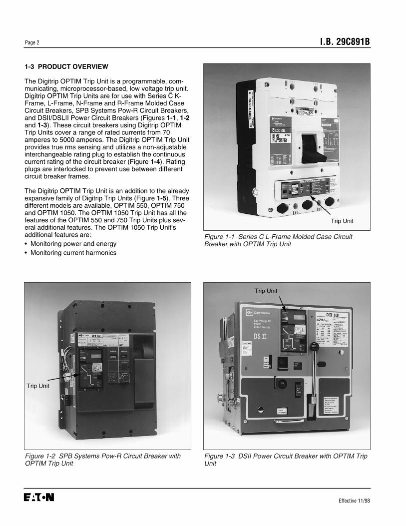
Figure 1-1 Series C L-Frame Molded Case CircuitBreaker with OPTIM Trip Unit
Figure 1-2 SPB Systems Pow-R Circuit Breaker withOPTIM Trip Unit
Figure 1-3 DSII Power Circuit Breaker with OPTIM TripUnit
1-3 PRODUCT OVERVIEW
The Digitrip OPTIM Trip Unit is a programmable, com-municating, microprocessor-based, low voltage trip unit.Digitrip OPTIM Trip Units are for use with Series C K-Frame, L-Frame, N-Frame and R-Frame Molded CaseCircuit Breakers, SPB Systems Pow-R Circuit Breakers,and DSII/DSLII Power Circuit Breakers (Figures 1-1, 1-2and 1-3). These circuit breakers using Digitrip OPTIMTrip Units cover a range of rated currents from 70amperes to 5000 amperes. The Digitrip OPTIM Trip Unitprovides true rms sensing and utilizes a non-adjustableinterchangeable rating plug to establish the continuouscurrent rating of the circuit breaker (Figure 1-4). Ratingplugs are interlocked to prevent use between differentcircuit breaker frames.
The Digitrip OPTIM Trip Unit is an addition to the alreadyexpansive family of Digitrip Trip Units (Figure 1-5). Threedifferent models are available, OPTIM 550, OPTIM 750and OPTIM 1050. The OPTIM 1050 Trip Unit has all thefeatures of the OPTIM 550 and 750 Trip Units plus sev-eral additional features. The OPTIM 1050 Trip Unit’sadditional features are:• Monitoring power and energy• Monitoring current harmonics
Trip Unit
Trip Unit
Trip Unit
I.B. 29C891B Page 3
Effective 11/98
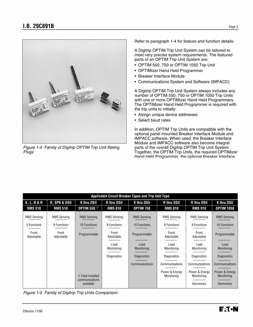
Figure 1-4 Family of Digitrip OPTIM Trip Unit RatingPlugs
Figure 1-5 Family of Digitrip Trip Units Comparison
Refer to paragraph 1-4 for feature and function details.
A Digitrip OPTIM Trip Unit System can be tailored tomeet very precise system requirements. The featuredparts of an OPTIM Trip Unit System are:• OPTIM 550, 750 or OPTIM 1050 Trip Unit• OPTIMizer Hand Held Programmer• Breaker Interface Module• Communications System and Software (IMPACC)
A Digitrip OPTIM Trip Unit System always includes anynumber of OPTIM 550, 750 or OPTIM 1050 Trip Unitswith one or more OPTIMizer Hand Held Programmers.The OPTIMizer Hand Held Programmer is required withthe trip units to initially:• Assign unique device addresses• Select baud rates
In addition, OPTIM Trip Units are compatible with theoptional panel mounted Breaker Interface Module andIMPACC software. When used, the Breaker InterfaceModule and IMPACC software also become integralparts of the overall Digitrip OPTIM Trip Unit System.Together, the OPTIM Trip Units, the required OPTIMizerHand Held Programmer, the optional Breaker Interface
K, L, N & R R, SPB & DSII K thru DSII R thru DSII K thru DSII R thru DSII R thru DSII K thru DSII
RMS 310 RMS 510 OPTIM 550 ➀ RMS 610 OPTIM 750 RMS 810 RMS 910 OPTIM 1050
RMS Sensing RMS Sensing RMS Sensing RMS Sensing RMS Sensing RMS Sensing RMS Sensing RMS Sensing
5 Functions 9 Functions 10 Functions 9 Functions 10 Functions 9 Functions 9 Functions 10 Functions
Front Front Programmable Front Programmable Front Front ProgrammableAdjustable Adjustable Adjustable Adjustable Adjustable
Load Load Load Load LoadMonitoring Monitoring Monitoring Monitoring Monitoring
Diagnostics Diagnostics Diagnostics Diagnostics Diagnostics
Communications Communications Communications Communications
Power & Energy Power & Energy Power & Energy➀ Field Installed Monitoring Monitoring Monitoringcommunications
available Harmonics Harmonics
Applicable Circuit Breaker Types and Trip Unit Type

I.B. 29C891BPage 4
Effective 11/98
Module, and the optional IMPACC software form a sys-tem that is capable of:• Setting trip units• Configuring systems• Monitoring/protecting• Displaying information• Diagnosing input• Testing trip units/circuit breakers• Communicating on sub-networks/networks
Application of low voltage circuit breakers utilizingOPTIM Trip Units generally fall into three primary cate-gories:
Stand Alone Application (Individual CircuitBreakers) These applications are utilized to take advantage of thesuperior protection and coordination features of DigitripOPTIM, and plan to perform monitoring at the circuitbreaker itself (Figure 1-6).
The following would be used:• OPTIM 550, 750 and/or 1050 Trip Units• One or more OPTIMizer Hand Held Programmers
Integrated Assembly Applications (Low VoltageAssemblies)These applications are utilized to provide on-gear orremote monitoring and even testing of compatibledevices (Figure 1-7). Up to 50 OPTIM Trip Units, DigitripRMS 810/910 Trip Units or IQ Energy Sentinels cancommunicate with one Breaker Interface Module.
The following would be used:• OPTIM 550 (if field IMPACC kit installed)• OPTIM 750 and/or 1050 Trip Units• Digitrip RMS 810 and/or 910 Trip Units• IQ Energy Sentinels• One or more OPTIMizer Hand Held Programmers• One or more assembly/remotely mounted Breaker
Interface Modules
Facility Wide Application (IMPACC System) These applications are utilized to tie together more than50 circuit breakers and/or other compatible devices. Inaddition, this permits taking advantage of PC-basedsoftware to improve diagnostics, power quality andenergy monitoring, or protective device coordinationcapabilities. The system would consist of any number ofdevices and software products, either within a facility oracross multiple facilities (Figure 1-8).
Figure 1-6 Hand Held Programmer in Use Figure 1-7 Breaker Interface Module in Service

I.B. 29C891B Page 5
Effective 11/98
The following would be used:• OPTIM 550 (if field IMPACC kit installed)• OPTIM 750 and/or 1050 Trip Units• Digitrip RMS 810 and/or 910 Trip Units• Other IMPACC Compatible devices• One or more OPTIMizer Hand Held Programmers• One or more assembly/remotely mounted Breaker
Interface Modules• IMPACC software/central PC
Refer to Figure 1-9 for typical system configurations uti-lizing the OPTIM Trip Unit System and other compatibledevices. For additional IMPACC details, refer to Section3 of Instruction Book 29C890.
1-4 FEATURES AND FUNCTIONS
Digitrip OPTIM 550, 750 and 1050 Trip Units provide awide range of common protection and coordination fea-tures and functions. The Digitrip OPTIM 1050 Trip Unitalso provides power quality and energy monitoring capa-bilities.
1-4.1 COMMON FEATURES OF DIGITRIP OPTIM550, 750 AND 1050 TRIP UNITS
Precise system coordination is provided by an expan-sive number of time-current curve shaping adjustments.This is accomplished by the large number of incremen-tal setpoints available for both current pickup and timesettings.
Programmable Protection and CoordinationAdjustments
• Long delay setting• Long delay time with selectable I2t or I4t slopes • Short delay setting• Short delay time with selectable flat or I2t slopes• Instantaneous setting• Ground fault setting• Ground fault time with selectable flat or I2t slopes
The trip units also have a selectable powered andunpowered thermal memory to provide protectionagainst cumulative overheating should a number ofoverload conditions occur in quick succession.
The trip unit information system utilizes LEDs to indicatethe trip mode following an automatic trip operation. TheLEDs are complemented by trip event information that is
stored in non-volatile memory after a trip condition. Thistrip information can then be accessed via the OptimizerHand Held Programmer, the Breaker Interface Module,or over the IMPACC System.
Selectable early warning alarms, such as the high loadcurrent alarm, are capable of being indicated locally andremotely. They are provided to help keep a systemoperating and productive.
System MonitoringAll OPTIM Trip Units are capable of monitoring the fol-lowing data:• Steady-State value of phase and neutral or ground
currents ➀
• Minimum and maximum current values• Average demand current• Cause of trip• Magnitude of fault current responsible for an automat-
ic trip operation
➀ LSI version of OPTIM 550 only monitors phase currents
Figure 1-8 Monitor and Control from Central PC
I.B. 29C891BPage 6
Effective 11/98
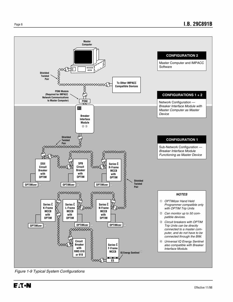
Figure 1-9 Typical System Configurations
MasterComputer
BreakerInterfaceModule
ShieldedTwistedPair
SPBCircuit Breaker
with OPTIM
DSIICircuitBreaker
withOPTIM
Series CR-Frame
MCCBwith
OPTIM
To Other IMPACCCompatible Devices
PONI
OPTIMizer
Series CN-Frame
MCCBwith
OPTIM
Series CL-FrameMCCBwith
OPTIM
Circuit Breaker
with RMS 810
or 910
Series CF-FrameMCCB
ES
IQ Energy Sentinel
ShieldedTwistedPair
PONI Module(Required for IMPACC
Network Communicationsto Master Computer)
ShieldedTwisted
Pair
➁ ➂
➃
OPTIMizer ➀➀ OPTIMizer ➀
OPTIMizer ➀OPTIMizer ➀
Series CK-Frame
MCCBwith
OPTIM
OPTIMizer ➀
NOTES
➀ OPTIMizer Hand HeldProgrammer compatible onlywith OPTIM Trip Units
➁ Can monitor up to 50 com-patible devices.
➂ Circuit breakers with OPTIMTrip Units can be directlyconnected to a master com-puter, and do not have to beconnected through the BIM.
➃ Universal IQ Energy Sentinelalso compatible with BreakerInterface Module.
CONFIGURATIONS 1 + 2
Network Configuration —Breaker Interface Module withMaster Computer as MasterDevice
CONFIGURATION 1
Sub-Network Configuration —Breaker Interface ModuleFunctioning as Master Device
CONFIGURATION 2
Master Computer and IMPACCSoftware

I.B. 29C891B Page 7
Effective 11/98
CommunicationsTrip units that are capable of two way communicationoperate via a network twisted pair for remote monitoringand control. The circuit breaker, through the trip unit, isable to respond to open and close commands via thecommunication network. To close the breaker, a motoroperator accessory is required. Refer to Table A.1 inAppendix A for motor operator instructional references.
TestingAn integral testing capability is part of all OPTIM TripSystems. The breaker can be tested in either the “Trip”or “No Trip” Test Mode. System level testing is carriedout by using a Hand Held Programmer, a BreakerInterface Module, or a remote computer. Bench leveltesting requires the Hand Held Programmer only. Triptests with the Hand Held Programmer require an auxil-iary power module to supply the necessary power. Tripunits continue to provide protection during test opera-tions.
Data AccessAll programming, information display and general tripunit access is accomplished through the use of one ormore of the following:• Hand Held Programmer • Breaker Interface Module ➀
• Remote computer ➀
1-4.2 ADDITIONAL FEATURES OF DIGITRIP OPTIM1050 TRIP UNITS
The Digitrip OPTIM 1050 Trip Unit provides all the basicsystem protection features outlined in Paragraph 1-4.1.In addition, Digitrip OPTIM 1050 Trip Units can providedata on power quality (current harmonics) and permitenergy monitoring.
Energy Monitoring
• Peak demand (kW)• Present demand (kW)• Forward energy (kWh)• Reverse energy (kWh)• Total energy (kWh)• Power factor
Power Quality
• Percentage harmonic content• Total harmonic distortion (THD)• Digitized waveforms (Remote computer only)
➀ OPTIM 550 trip units must have field IMPACC kitinstalled for use with BIM or remote computer
I.B. 29C891BPage 8
Effective 11/98
SECTION 2: HARDWARE DESCRIPTIONAND EQUIPMENT INTERFACES
2-1 GENERAL
The purpose of this section is to familiarize the readerwith Digitrip OPTIM Trip Units, their nomenclature, theway trip units are interfaced with specific equipment,and trip unit specifications. The information presented isdivided into the following four parts:• General Trip Unit Details• Trip Units By Type• Trip Unit Accessories• Specification Summary
2-2 GENERAL TRIP UNIT DETAILS
This section describes general trip unit functioning, tripunit hardware, circuit breaker specific details, andrequired interfaces with other external equipment.
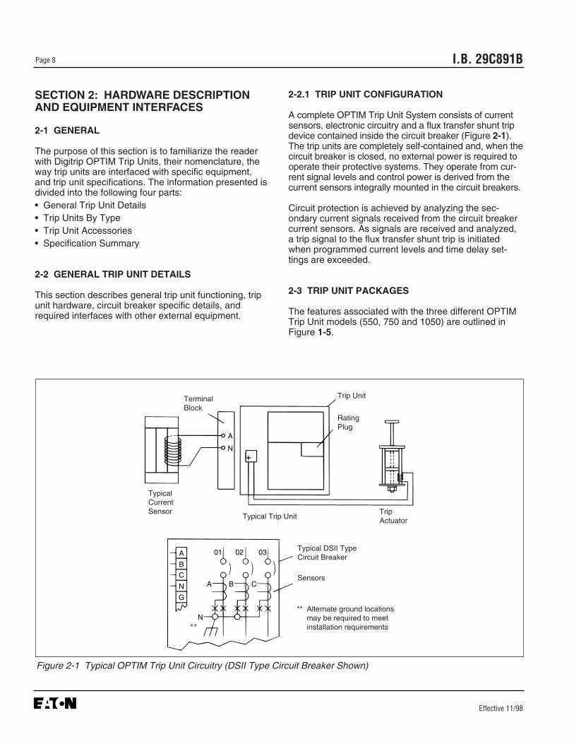
2-2.1 TRIP UNIT CONFIGURATION
A complete OPTIM Trip Unit System consists of currentsensors, electronic circuitry and a flux transfer shunt tripdevice contained inside the circuit breaker (Figure 2-1).The trip units are completely self-contained and, when thecircuit breaker is closed, no external power is required tooperate their protective systems. They operate from cur-rent signal levels and control power is derived from thecurrent sensors integrally mounted in the circuit breakers.
Circuit protection is achieved by analyzing the sec-ondary current signals received from the circuit breakercurrent sensors. As signals are received and analyzed,a trip signal to the flux transfer shunt trip is initiatedwhen programmed current levels and time delay set-tings are exceeded.
2-3 TRIP UNIT PACKAGES
The features associated with the three different OPTIMTrip Unit models (550, 750 and 1050) are outlined inFigure 1-5.
Figure 2-1 Typical OPTIM Trip Unit Circuitry (DSII Type Circuit Breaker Shown)
A
B
C
N
G
A B C
N
01 02 03
A
N
Terminal Block
RatingPlug
Trip Unit
TripActuatorTypical Trip Unit
Typical DSII TypeCircuit Breaker
Sensors
** Alternate ground locationsmay be required to meetinstallation requirements
TypicalCurrentSensor
**

I.B. 29C891B Page 9
Effective 11/98
Models 750 and 1050 on K, L and N-Frame circuitbreakers are factory sealed. Model 550 equipped circuitbreakers and all R-Frame SPB and DSII circuit breakerscan be upgraded in the field.
2-4 SERIES C K, L-FRAME AND N-FRAME OPTIMTRIP UNITS
The continuous frame rating of each circuit breaker isselectable via rating plugs over the following range:• K-Frame (70-400 amperes)• L-Frame (200-600 amperes)• N-Frame (400-1200 amperes)
The OPTIM Trip Unit applicable to the Series C K and L-Frame molded case circuit breakers extends approxi-mately 0.5 inches beyond the front of the breaker cover(Figure 2-2). The OPTIM Trip Unit used with the L-Frame is not applicable to any other circuit breaker.
The OPTIM Trip Unit applicable to Series C N-Framemolded case circuit breaker is nearly flush mounted tothe front of the breaker cover (Figure 2-3). The OPTIMTrip Unit used with the N-Frame is not applicable to anyother circuit breaker.
The side wiring brackets shown in Figures 2-2 and 2-3are only necessary for Models 750 and 1050 on K, L
and N-Frame circuit breakers. Model 550 does notneed the bracket on the same frames.
2-4.1 K, L AND N-FRAME OPTIM TRIP UNITDISPLAYS
Readings are displayed and protective settings estab-lished or adjusted through the use of one or more of thefollowing means:• OPTIMizer Hand Held Programmer• Breaker Interface Module• Remote Computer/IMPACC software
OPTIM Trip Units provide the following features (Figure2-4):
Push-To-Trip ButtonA Push-To-Trip button provides a local manual meansfor checking the circuit breaker’s mechanical trippingfunction and periodically exercising the operating mech-anism. It is located on the front of the trip unit.
Mode of Trip/Alarm IndicatorsFour LED type indicators (long delay, short delay,instantaneous and ground fault trip or ground faultalarm) are provided to indicate the mode of trip after anautomatic trip. The appropriate LED is lit red when acti-vated.
Figure 2-2 OPTIM Trip Unit Mounted in Series C L-Frame Circuit Breaker (K-Frame is Similar)
Figure 2-3 OPTIM Trip Unit Mounted in Series C N-Frame Circuit Breaker

I.B. 29C891BPage 10
Effective 11/98
Notice: Trip unit should be powered from an externalcontrol power source. If control power is notavailable the LEDs will temporatily operate offthe battery. Refer to the wiring diagrams list-ed in Appendix A, Table A.1 for control powerconnections.
Battery for Trip IndicatorsA replaceable 3 volt lithium battery is located behind asmall access cover on the left side of the trip unit(Figure 2-5). A test pushbutton and LED test indicatorare also provided. The test pushbutton will energize theLED indicator if the battery is in good working condition.Refer to paragraph 5-4.1 for battery replacement infor-mation.
Trip Indicator Reset PushbuttonA trip reset pushbutton is provided to turn off a mode oftrip LED indicator after an automatic trip. The resetpushbutton is located next to the four mode of trip ledindicators.
Figure 2-4 Front View of L-Frame Type OPTIM Trip Unit (K and N-Frame Designs are Similar)
Figure 2-5 K, L and N-Frame Type OPTIM Trip UnitBattery Compartment
➅
➀ Push-to-Trip Button➁ Mode of Trip/Alarm LEDs➂ Battery Test Pushbutton/LED➃ Automatic Trip Indicator Reset
Pushbutton
➄ Unit Status LED➅ INCOM Transmit LED (Model 550 requires field IMPACC kit)➆ Battery Compartment/Pro-gramming Port Access Cover➇ Rating Plug
➄
➆
➀
➃
➇ ➂ ➁
I.B. 29C891B Page 11
Effective 11/98
covering the OPTIMizer Hand HeldProgrammer for the recommended connectionand power application sequence.
2-5 SERIES C R-FRAME, SPB AND DSII/DSLIIOPTIM TRIP UNITS
Model 750 and 1050 OPTIM Trip Units used in Series CR-Frame, SPB Systems Pow-R and DSII/DSLII circuitbreakers are field replaceable. Model 550 is only avail-able on the R-Frame circuit breaker. For each of thesecircuit breaker types, rating plugs are used to select thecontinuous ampere rating of the circuit breaker. The rat-ing plugs and circuit breakers are keyed with a mechani-cal interlock to prevent incorrect installation. The contin-uous ampere rating of each of these circuit breakers isadjustable via the rating plugs as follows:• Series C R-Frame (800-2500 amperes) (Figure 2-7)• SPB Pow-R (200-5000 amperes) (Figure 2-8)• DSII/DSLII (100-5000 amperes) (Figure 2-9)
Refer to Table 2.1 for the available rating plug values bycircuit breaker type.
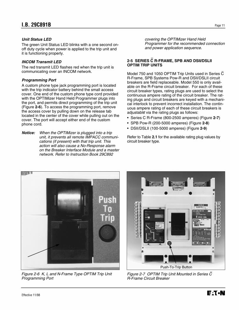
Unit Status LEDThe green Unit Status LED blinks with a one second on-off duty cycle when power is applied to the trip unit andit is functioning properly.
INCOM Transmit LEDThe red transmit LED flashes red when the trip unit iscommunicating over an INCOM network.
Programming PortA custom phone type jack programming port is locatedwith the trip indicator battery behind the small accesscover. One end of the custom phone type cord providedwith the OPTIMizer Hand Held Programmer plugs intothe port, and permits direct programming of the trip unit(Figure 2-6). To access the programming port, removethe access cover by pulling down on the release tablocated in the center of the cover while pulling out on thecover. The port will accept either end of the customphone cord.
Notice: When the OPTIMizer is plugged into a tripunit, it prevents all remote IMPACC communi-cations (if present) with that trip unit. Thisaction will also cause a No-Response alarmon the Breaker Interface Module and a masternetwork. Refer to Instruction Book 29C892
Figure 2-6 K, L and N-Frame Type OPTIM Trip UnitProgramming Port
Figure 2-7 OPTIM Trip Unit Mounted in Series C R-Frame Circuit Breaker
Push-To-Trip Button
I.B. 29C891BPage 12
Effective 11/98
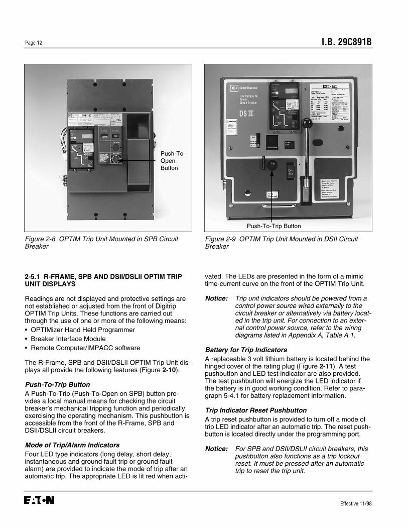
2-5.1 R-FRAME, SPB AND DSII/DSLII OPTIM TRIPUNIT DISPLAYS
Readings are not displayed and protective settings arenot established or adjusted from the front of DigitripOPTIM Trip Units. These functions are carried outthrough the use of one or more of the following means:• OPTIMizer Hand Held Programmer• Breaker Interface Module• Remote Computer/IMPACC software
The R-Frame, SPB and DSII/DSLII OPTIM Trip Unit dis-plays all provide the following features (Figure 2-10):
Push-To-Trip ButtonA Push-To-Trip (Push-To-Open on SPB) button pro-vides a local manual means for checking the circuitbreaker’s mechanical tripping function and periodicallyexercising the operating mechanism. This pushbutton isaccessible from the front of the R-Frame, SPB andDSII/DSLII circuit breakers.
Mode of Trip/Alarm IndicatorsFour LED type indicators (long delay, short delay,instantaneous and ground fault trip or ground faultalarm) are provided to indicate the mode of trip after anautomatic trip. The appropriate LED is lit red when acti-
Figure 2-8 OPTIM Trip Unit Mounted in SPB CircuitBreaker
vated. The LEDs are presented in the form of a mimictime-current curve on the front of the OPTIM Trip Unit.
Notice: Trip unit indicators should be powered from acontrol power source wired externally to thecircuit breaker or alternatively via battery locat-ed in the trip unit. For connection to an exter-nal control power source, refer to the wiringdiagrams listed in Appendix A, Table A.1.
Battery for Trip IndicatorsA replaceable 3 volt lithium battery is located behind thehinged cover of the rating plug (Figure 2-11). A testpushbutton and LED test indicator are also provided.The test pushbutton will energize the LED indicator ifthe battery is in good working condition. Refer to para-graph 5-4.1 for battery replacement information.
Trip Indicator Reset PushbuttonA trip reset pushbutton is provided to turn off a mode oftrip LED indicator after an automatic trip. The reset push-button is located directly under the programming port.
Notice: For SPB and DSII/DSLII circuit breakers, thispushbutton also functions as a trip lockoutreset. It must be pressed after an automatictrip to reset the trip unit.
Figure 2-9 OPTIM Trip Unit Mounted in DSII CircuitBreaker
Push-To-Trip Button
Push-To-OpenButton
I.B. 29C891B Page 13
Effective 11/98
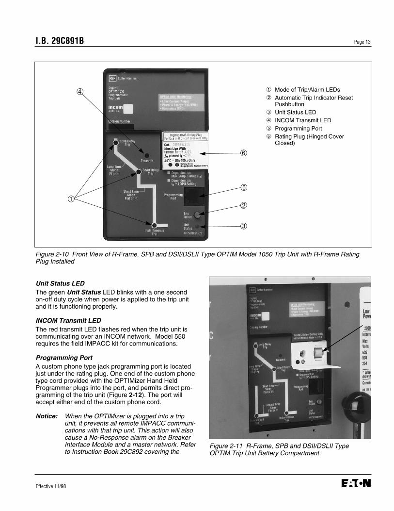
Unit Status LEDThe green Unit Status LED blinks with a one secondon-off duty cycle when power is applied to the trip unitand it is functioning properly.
INCOM Transmit LEDThe red transmit LED flashes red when the trip unit iscommunicating over an INCOM network. Model 550requires the field IMPACC kit for communications.
Programming PortA custom phone type jack programming port is locatedjust under the rating plug. One end of the custom phonetype cord provided with the OPTIMizer Hand HeldProgrammer plugs into the port, and permits direct pro-gramming of the trip unit (Figure 2-12). The port willaccept either end of the custom phone cord.
Notice: When the OPTIMizer is plugged into a tripunit, it prevents all remote IMPACC communi-cations with that trip unit. This action will alsocause a No-Response alarm on the BreakerInterface Module and a master network. Referto Instruction Book 29C892 covering the
Figure 2-10 Front View of R-Frame, SPB and DSII/DSLII Type OPTIM Model 1050 Trip Unit with R-Frame RatingPlug Installed
➀ Mode of Trip/Alarm LEDs➁ Automatic Trip Indicator Reset
Pushbutton➂ Unit Status LED➃ INCOM Transmit LED➄ Programming Port➅ Rating Plug (Hinged Cover
Closed)
➂
➀➁
➅
➃
➄
Figure 2-11 R-Frame, SPB and DSII/DSLII TypeOPTIM Trip Unit Battery Compartment

I.B. 29C891BPage 14
Effective 11/98
OPTIMizer Hand Held Programmer for therecommended connection and power applica-tion sequence.
2-6 OPTIM TRIP UNIT RATING PLUG
The rating plug value (In) determines the maximum con-tinuous current rating of the circuit breaker. All the pro-tection function settings are based on multiples of theplug rating. These settings are displayed as actualampere values for ease of use.
Notice: The primary current conductors (cable or bus)must have ampacity ratings equal to the rat-ing plug value per NEC Section 240-6(b).
OPTIM Trip Units use interchangeable rating plugs(Figure 2-13). Rating plugs are designed for use withone specific circuit breaker type. The circuit breaker typeis indicated on the rating plug. Rating plugs are suitablefor both 50 and 60Hz operation. A rating plug must beselected to match the desired continuous current ratingof the circuit breaker as well as the installed sensor rat-ing. The available rating plugs are shown in Table 2.1.
Figure 2-12 OPTIMizer Shown Connected to Program-ming Port of DSII Type Circuit Breaker
Figure 2-13 Family of OPTIM Trip Unit Rating Plugs
➀
➁➂
➃
➄
➅
➆
➆➇
➆
➀ DSII/DSL II Rating Plug➁ SPB Pow-R Rating Plug➂ R-Frame Rating Plug
(Hinged Access Cover Open)➃ N-Frame Rating Plug➄ L-Frame Rating Plug
(K-Frame Similar)➅ Retention Shaft➆ Access to Retention Device➇ Connector Pin
I.B. 29C891B Page 15
Effective 11/98
All rating plugs are designed with a rejection feature toprevent interchanging between different circuit breakertypes. In addition, the circuit breaker will trip if a ratingplug is removed with the trip unit energized.
BEFORE A RATING PLUG IS INSTALLED INTO THETRIP UNIT, BE CERTAIN TO CHECK THAT THEBREAKER TYPE AND FRAME RATING (OR SENSORRATING IF APPLICABLE) MATCH THOSE PRINTEDON THE RATING PLUG COVER. INSTALLING ARATING PLUG THAT DOES NOT MATCH THEBREAKER TYPE AND FRAME RATING (OR SENSORRATING IF APPLICABLE) CAN PRODUCE SERIOUSMISCOORDINATION AND/OR FAILURE OF THEPROTECTION SYSTEM.
IN ADDITION, IT IS IMPORTANT TO MAKE SURETHAT A RATING PLUG IS PROPERLY INSTALLEDAND SECURED TO ENSURE PROPER FUNCTION-ING OF THE CIRCUIT BREAKER.
2-7 EXTERNAL OPTIM TRIP UNIT ACCESSORIES
Digitrip OPTIM Trip Units for K, L, and N-Frame circuitbreakers utilize a number of accessory items mountedoutside the circuit breaker (Figure 2-14). R-Frame, SPBand DSII circuit breakers have these devices alreadyinstalled internally. Refer to Table 2.2 for specificaccessory details, catalog numbers and/or approvedaccessory items.
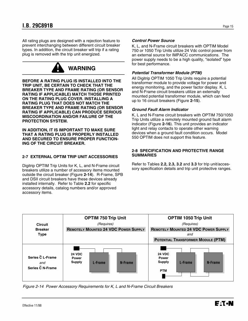
Figure 2-14 Power Accessory Requirements for K, L and N-Frame Circuit Breakers
OPTIM 750 Trip Unit OPTIM 1050 Trip Unit(Requires) (Requires)
REMOTELY MOUNTED 24 VDC POWER SUPPLY REMOTELY MOUNTED 24 VDC POWER SUPPLY
and
POTENTIAL TRANSFORMER MODULE (PTM)
Circuit Breaker
Type
Series C L-Frame
and
Series C N-Frame
24 VDCPowerSupply N-FrameL-Frame
24 VDCPowerSupply N-FrameL-Frame
PTM
Control Power SourceK, L, and N-Frame circuit breakers with OPTIM Model750 or 1050 Trip Units utilize 24 Vdc control power froman external source for IMPACC communications. Thepower supply needs to be a high quality, “isolated” typefor best performance.
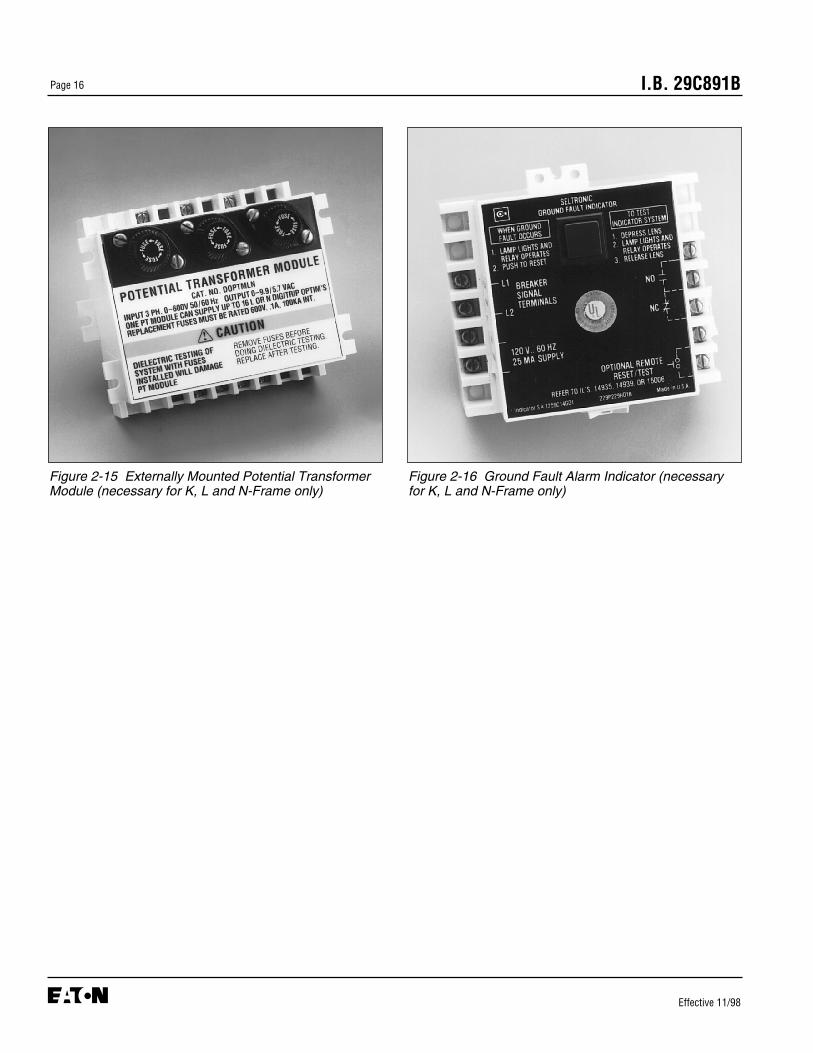
Potential Transformer Module (PTM)All Digitrip OPTIM 1050 Trip Units require a potentialtransformer module to provide voltage for power andenergy monitoring, and the power factor display. K, Land N-Frame circuit breakers utilize an externallymounted potential transformer module, which can feedup to 16 circuit breakers (Figure 2-15).
Ground Fault Alarm IndicatorK, L and N-Frame circuit breakers with OPTIM 750/1050Trip Units utilize a remotely mounted ground fault alarmindicator (Figure 2-16). This unit provides an indicatorlight and relay contacts to operate other warningdevices when a ground fault condition occurs. Model550 OPTIM does not support this feature.
2-8 SPECIFICATION AND PROTECTIVE RANGESUMMARIES
Refer to Tables 2.2, 2.3, 3.2 and 3.3 for trip unit/acces-sory specification details and trip unit protective ranges.
WARNING
I.B. 29C891BPage 16
Effective 11/98
Figure 2-15 Externally Mounted Potential TransformerModule (necessary for K, L and N-Frame only)
Figure 2-16 Ground Fault Alarm Indicator (necessaryfor K, L and N-Frame only)

I.B. 29C891B Page 17
Effective 11/98
Table 2.1 Rating Plugs Applicable to All OPTIM Trip Units
Series C Series C Series C Series C SPB Systems DSII/DSLIIK-Frame Breaker L-Frame Breaker N-Frame Breaker R-Frame Breaker Pow-R Breakers Breakers
Rating Plug (In) Frame Rating Rating Plug (In) Frame Rating Rating Plug (In) Frame Rating Rating Plug (In) Frame Rating Rating Plug (In) Frame Rating Rating Plug (In) Sensor Rating(Amperes) (Amperes) (Amperes) (Amperes) (Amperes) (Amperes) (Amperes) (Amperes) (Amperes) (Amperes) (Amperes) (Amperes)
63 125 ➀ 125 400 800 800 1600 200 400 100 20070 63 450 1000 250 20090 70 500 1200 300 200 300100 90 550 1600 400 250110 100 600 1000 2000 400 800 300125 110 700 1200 600 200 400125 250 125 800 1600 800 250150 ➀ 250 600 1200 2000 600 1200 300175 125 700 1600 2500 800 400200 150 800 2000 1000 300 600225 175 1000 2500 1200 400250 200 1200 800 1600 600200 400 225 1000 400 800225 250 1200 600250 200 400 1600 800300 225 1000 2000C 600 1200350 250 1200 800400 300 1600 1000
350 2000 1200400 1600 2000 800 1600300 600 2000 1000350 1600 2500 1200400 2000 1600500 2500 1000 2000600 1600 3000 1200
2000 16002500 20003000 1600 24002000 4000 20002500 24003000 1600 32003200 20004000 24003000 5000 30003200 32004000 2000 40005000 2400
320040003200 500040005000
➀ Not available on Model 550

I.B. 29C891BPage 18
Effective 11/98
Table 2.2 OPTIM Trip Unit/Accessory Specifications
Environment:• Operating Temperature -20°C to 85°C• Storage Temperature -30°C to 85°C• Operating Humidity 0 to 95% Relative Humidity
(non-condensing)
Frequency 50/60Hz
Protective Settings Refer to Table 3.1
Zone Selective Interlocking • Short Delay• Ground Fault
Metering Tolerance Refer to Table 2.3
Auxiliary Switch/Bell Alarm• Contact Ratings • AC - 6A @ 600 Vac
• DC - 0.5A @ 125 Vdc0.25A @ 250 Vdc
Ground Fault Indicator • AC Contact Ratings(Style 1259C14G01) - 5A @ 240 Vac
- 1/6 HP @ 120 Vac- 1/3 HP @ 240 Vac
• DC Contact Ratings- 5A @ 28 Vdc- 0.5A @ Vdc
• Power Source- 120 Vac- 50/60 Hz
• Dimensions (inches)- 4.75 x 3.94 x 3.00
Potential Transformer Module (PTM)(Catalog DOPTMLN, Style 7801C54G01)
• Input voltage terminals LA, LB and LC• Rated input voltage 0 to 600 volts line to line• Input volt amps 1 VA per phase• Output voltage terminals A, B, C and N• Ratio ± 2% (Input) (Output)
240V L-L 2.25V L-N480V L-L 4.50V L-N600V L-L 5.53V L-N
• Dimensions (inches) 4.75 x 5.75 x 3.28• One PTM Can supply up to 16 L or N-Frame
Circuit Breakers
Power SupplyOptim Trip Units impsoe a load of 45ma at 24 Vdc. The power supply should be a high quality, isolated unit with both UL (UR) and CE labels.
Cause of Trip Battery• Type Lithium, 3 volt• Acceptable Replacement • Varta Batteries, Inc.
150 Clarbrook RoadElmsford, NY 10523
Type CR 1/3N
• DuracellSouth BroadwayTarrytown, NY 10591
Type DL 1/3N
• Sanyo Electric, Inc.Battery Div.200 Riser RoadLittle Ferry, NJ 07643
Type CR 1/3N
TRIP UNITS
ACCESSORIES

I.B. 29C891B Page 19
Effective 11/98
Table 2.3 OPTIM Trip Unit Metering Tolerances ➀
Parameter Circuit Breaker Type Accuracy Range/Assumptions
Phase Current K, L, N ±2% Frame Current Rating 5% to 100% Frame RatingR, SPB ±2% Frame Current Rating 5% to 100% (Current)DSII, DSLII ±2% Sensor Current Rating Sensor Rating
Ground Current K, L, N ±5% Frame Current Rating 10% to 100% FrameR, SPB ±5% Frame Current Rating 10% to 100% FrameDSII, DSLII ±5% Sensor Current Rating 10% to 100% Current Sensor
Power and Peak K, L, N ±4% of (Frame Current Rating x 600V) x 3 ~ 1 sec. sampling windowDemand R, SPB ±4% of (Frame Current Rating x 600V) x 3 - Current @ 5% to 175% of frame
DSII, DSLII ±4% of (Current Sensor Rating x 600V) x 3 or sensor rating
System Power Factor K, L, N ±0.02 Balanced threeR, SPB ±0.02 Phase Load perDSII, DSLII ±0.02 ANSI Std. C12.1-1988
Energy K, L, N ±5% of (Frame Current Rating x 600V x time) x 3 5% to 175% of Plug Rating InR, SPB ±5% of (Frame Current Rating x 600V x time) x 3DSII, DSLII ±5% of (Current Sensor Rating x 600V x time) x 3
Notes:➀ Metered values are displayed via:
1. OPTIMizer Hand Held Programmer2. Breaker Interface Module3. Remote PC via IMPACC

I.B. 29C891BPage 20
Effective 11/98
SECTION 3: OPERATION AND FUNCTION-ALITY
3-1 GENERAL
This section describes the details associated with theoperation and functional use of Digitrip OPTIM TripUnits in terms four main categories:• Protection and Coordination• System Monitoring
- Load Current Monitoring- Power and Energy Monitoring- Power Quality Monitoring
• Communications• Testing
Four quick reference overviews outlining the featuresavailable with the Digitrip OPTIM Trip Unit System, andspecifically OPTIM Trip Units, are provided in Tables3.1, 3.2 , 3.3 and 3.4.
OPTIM Trip Units provide true RMS current sensing forproper correlation with thermal characteristics of con-ductors and equipment. The rating plug (In) determinesthe continuous current rating of the circuit breaker.
3-2 PROTECTION AND COORDINATION
The Digitrip OPTIM Trip Unit provides circuit breakers withan extensive degree of selective coordination potential,and permits curve shaping over a wide range of currentsettings. Pickup settings, delay time settings and slopeselections are addressed here with respect to their effecton the resultant characteristic curve.
3-2.1 OVER-TEMPERATURE TRIP
The OPTIM Trip Unit is designed for use in environ-ments where the ambient temperatures range from -20°C to +85°C. If, however, temperatures around thetrip unit exceed this range, the trip unit performancemay be degraded. To insure that the tripping function isnot compromised due to an over-temperature condition,the OPTIM microcomputer chip has a built-in over- tem-perature protection feature. This protective feature isfactory set to trip the circuit breaker if the chip tempera-ture exceeds 85°C ± 10°C.
3-2.2 CHARACTERISTIC CURVE REVIEW
As a review, certain aspects of a circuit breaker’s char-acteristic curve are discussed here to simplify the under-standing of later material.
The operating response of the trip unit is graphicallyrepresented by time-current characteristic curves.These curves show how and when a particular trip unitwill act for given values of time and current. The moreversatile the trip unit, the easier it is to accomplish closecoordination and achieve optimum protection.
A characteristic curve is represented by a band createdby a minimum and maximum value of time or current(Figure 3-1). Minimum and maximum values are general-ly the result of tolerances introduced by the manufactur-ing process for components and factory calibrationefforts. The tolerances are usually stated as the trip unit’saccuracy and specified on the time-current curves. Thisaccuracy is stated in terms of a plus or minus percentageand represents a permitted fluctuation on either side of aselected nominal setting point for a trip unit. OPTIM TripUnit accuracies are specified for each protective function(long delay, short delay instantaneous and ground fault)and the type of circuit breaker in which the trip unit isinstalled. Refer to the applicable OPTIM time-currentcurves outlined in Table A.1 of Appendix A for specificaccuracies.
The programmable or adjustable features of a trip unitpermit movement of its characteristic curve or parts ofthe curve. This movement can be done in both a hori-zontal and vertical direction on the time-current grid(Figure 3-2).
The actual shape of the curve can be changed byselecting the slope, such as Flat, I2t and I4t (Figure 3-3).An I2t slope selection is used for an inverse curve, an I4tslope selection for an extremely inverse curve, and aFlat selection for a definite or fixed time curve.
Capability OPTIM 550 OPTIM 750 OPTIM 1050
Protection and Yes Yes YesCoordination (10 functions) (10 functions) (10 functions)
IMPACC Field Yes YesCommunications Upgradeable
Ground Alarm No Yes➀ Yes➀
Contact
Zone Selective No Yes Yes Interlocking
Power Quality No No Yes
Energy Monitoring No No Yes➀
➀ Requires external module on K, L and N-Frame breakers
Table 3.1 Digitrip OPTIM 550, 750 and 1050 Trip UnitCapabilities

I.B. 29C891B Page 21
Effective 11/98
Before discussing protection functions individually, keepin mind that combining functional capabilities, such aslong, short and instantaneous, is a coordination activity.The effects of one set of settings on another set shouldbe carefully evaluated to determine if the results for allpossible circumstances are acceptable.
Example:
• Consider programming the protective functions of a400 ampere Series C L-Frame circuit breaker with aninstalled 200 ampere rating plug value (In). OPTIMtrips are set up with actual values of current instead ofper unit settings.
• The Long Delay Setting (Ir) is to be 100 amperes andthe Short Delay Pickup is to be 200 amperes.
• The Long Delay Setting (Ir) is programmable from 0.4- 1.0 times the rating plug value (In) for the L-Frame.For this example, the Long Delay Setting (Ir) is pro-grammed to 0.5 (In) = 0.5 (200) = 100 amperes, therequired Long Delay Setting (Ir).
• The Short Delay Pickup is programmable from 1.5 -8.0 times the Long Delay Setting (Ir) for the L-Frame.For this example, the Short Delay Pickup is pro-grammed to 2.0 (Ir) = 2.0 (100) = 200 amperes, therequired Short Delay Pickup.
TIM
E
CURRENT
Intermediate
Minimum
Maximum
Figure 3-2 Typical Trip Curve Horizontal Movement
TIM
E
CURRENT
I4t Slope
I2t Slope
Figure 3-3 Typical Long Delay Time Slope Adjustment
TIM
E
CURRENT
(Pickup Accuracy)Actual pickup will occur within ± % of any selected pickup setting
(Timing Accuracy)Actual Trip Time will be within ± % of any selected trip time setting
Trip TimeSetting
Pickup Setting
Figure 3-1 Sample of Partial Time-Current Trip Curve

I.B. 29C891BPage 22
Effective 11/98
TRIP UNIT TYPE DIGITRIP OPTIM 550RMS Sensing YesProgrammable YesCIRCUIT BREAKERSTypes Series C K, L and N-Frames Series C R-FramesAmpere Range 70 - 1200A 800 - 2500AInterrupting Rating @ 480V 30 thru 100KA 65 thru 100KATRIP UNIT ORDERING OPTIONSLSI ➀ ➁ Yes Yes LSIG ➀ ➁ Yes YesLSIA (Remote over IMPACC only) Yes YesPROTECTION AND COORDINATIONInterchangeable Rating Plug (In) 70-1200A 800-2500AOver-Temperature Trip Yes YesLONG DELAY PROTECTIONLong Delay Setting (Ir) ➂ 0.4 - 1.0 x In (0.01 steps) 0.4 - 1.0 x In (0.01 steps)Long Delay Pickup 116% of Ir 116% of IrLong Delay Time I2t @ 6 x Ir ➃ 2-24 secs (0.10 steps) 2-24 secs (0.10 steps)Long Delay Time I4t @ 6 x Ir (SDT Slope Flat only) ➄ 1-5 secs (0.10 steps) 1-5 secs (0.10 steps)Long Delay Thermal Memory (Powered or Unpowered) Yes (programmable) Yes (programmable)High Load Alarm 0.5 - 1.0 x Ir 0.5 - 1.0 x IrSHORT DELAY PROTECTIONShort Delay Pickup ➂ 1.5 - 8.0 x Ir (0.1 steps) 1.5 - 8.0 x Ir (0.1 steps)
Short Delay Time I2t @ 8 x Ir ➅ 0.1 - 0.5 secs (0.01 steps) 0.1 - 0.5 secs (0.01 steps)Short Delay Time Flat ➅ 0.1 - 0.5 secs (0.01 steps) 0.1 - 0.5 secs (0.01 steps)Zone Selective Interlocking No NoINSTANTANEOUS PROTECTIONInstantaneous Pickup ➆ 2.0 - 8.0 x In (0.1 steps) 2.0 - 10.0 x In (0.1 steps)
(1600 & 2000A)2.0 - 6.0 x In (0.1 steps)
(2500A)Discriminator Yes YesOverride (Fixed Instantaneous) ➇ Yes YesGROUND FAULT PROTECTIONGround Fault Alarm (not to exceed 1200A) ➈ 0.2 - 1.0 x Is (0.01 steps) 0.24 - 1.0 x In (0.01 steps)Ground Fault Pickup (not to exceed 1200A) ➆ 0.2 - 1.0 x Is (0.01 steps) 0.24 - 1.0 x In (0.01 steps)Ground Fault Delay I2t @ 0.62 x In/Is ➉ 0.1 - 0.5 secs (0.01 steps) 0.1 - 0.5 secs (0.01 steps)Ground Fault Delay Flat 0.1 - 0.5 secs (0.01 steps) 0.1 - 0.5 secs (0.01 steps)Zone Selective Interlocking No NoGround Fault Memory Yes YesSYSTEM MONITORINGDigital Display Yes (Using OPT) Yes (Using OPT)Current Yes YesCause of Trip LEDs Yes YesMagnitude of Trip Information Yes YesRemote Signal Contacts No NoPower and Energy No NoPower Quality - Harmonics No NoPower Factor No NoCOMMUNICATIONSIMPACC Field Upgradeable Field UpgradeableTESTINGTesting Method OPT, BIM, IMPACC OPT, BIM, IMPACC
➀ No ground fault alarm (A) provided➁ Refer to para. 3-2.3 and Figure 3-4 for details➂ Setting Tolerance ±5%➃ Setting Tolerance +0-30%➄ Setting Tolerance +10-40%
Notes:In = Rating PlugIr = Long Delay SettingIs = Sensor RatingOPT = Hand Held Programmer (OPTIMizer)BIM = Breaker Interface Module
➅ Setting Tolerance (See time-current curves)➆ Setting Tolerance ±10%➇ Setting Tolerance ±20%➈ Only available with LSIA➉ Is (K, L & N-Frame), In (R-Frame, SPB)
Contact factory or Vista for K-Frame availability
Table 3.2 Digitrip OPTIM 550 Trip Unit System Capabilities Overview
11
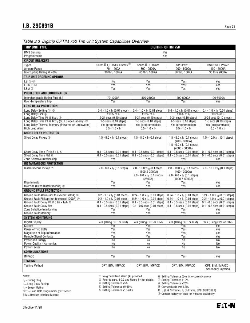
I.B. 29C891B Page 23
Effective 11/98
TRIP UNIT TYPE DIGITRIP OPTIM 750RMS Sensing YesProgrammable YesCIRCUIT BREAKERSTypes Series C K, L and N-Frames»` Series C R-Frames SPB Pow-R DSII/DSLII PowerAmpere Range 70 - 1200A 800 - 2500A 200 - 5000A 100 - 5000AInterrupting Rating @ 480V 30 thru 100KA 65 thru 100KA 50 thru 150KA 30 thru 200KATRIP UNIT ORDERING OPTIONSLSI ➀ ➁ No Yes Yes YesLSIG ➀ ➁ Yes Yes Yes YesLSIA ➁ Yes Yes Yes YesPROTECTION AND COORDINATIONInterchangeable Rating Plug (In) 70-1200A 800-2500A 200-5000A 100-5000AOver-Temperature Trip Yes Yes Yes YesLONG DELAY PROTECTIONLong Delay Setting (Ir) ➂ 0.4 - 1.0 x In (0.01 steps) 0.4 - 1.0 x In (0.01 steps) 0.4 - 1.0 x In (0.01 steps) 0.4 - 1.0 x In (0.01 steps)Long Delay Pickup 116% of Ir 116% of Ir 116% of Ir 105% or IrLong Delay Time I2t @ 6 x Ir ➃ 2-24 secs (0.10 steps) 2-24 secs (0.10 steps) 2-24 secs (0.10 steps) 2-24 secs (0.10 steps)Long Delay Time I4t @ 6 x Ir (SDT Slope Flat only) ➄ 1-5 secs (0.10 steps) 1-5 secs (0.10 steps) 1-5 secs (0.10 steps) 1-5 secs (0.10 steps)Long Delay Thermal Memory (Powered or Unpowered) Yes (programmable) Yes (programmable) Yes (programmable) Yes (programmable)High Load Alarm 0.5 - 1.0 x Ir 0.5 - 1.0 x Ir 0.5 - 1.0 x Ir 0.5 - 1.0 x IrSHORT DELAY PROTECTIONShort Delay Pickup ➂ 1.5 - 8.0 x Ir (0.1 steps) 1.5 - 8.0 x Ir (0.1 steps) 1.5 - 8.0 x Ir (0.1 steps) 1.5 - 10.0 x Ir (0.1 steps)
(400 - 3000A)1.5 - 6.0 x Ir (0.1 steps)
(4000 - 5000A)Short Delay Time I2t @ 8 x Ir ➅ 0.1 - 0.5 secs (0.01 steps) 0.1 - 0.5 secs (0.01 steps) 0.1 - 0.5 secs (0.01 steps) 0.1 - 0.5 secs (0.01 steps)Short Delay Time Flat ➅ 0.1 - 0.5 secs (0.01 steps) 0.1 - 0.5 secs (0.01 steps) 0.1 - 0.5 secs (0.01 steps) 0.1 - 0.5 secs (0.01 steps)Zone Selective Interlocking Yes Yes Yes YesINSTANTANEOUS PROTECTIONInstantaneous Pickup ➆ 2.0 - 8.0 x In (0.1 steps) 2.0 - 10.0 x In (0.1 steps) 2.0 - 10.0 x In (0.1 steps) 2.0 - 10.0 x In (0.1 steps)
(1600 & 2000A) (400 - 3000A)2.0 - 6.0 x In (0.1 steps) 2.0 - 6.0 x In (0.1 steps)
(2500A) (4000 & 5000A)Discriminator Yes Yes Yes YesOverride (Fixed Instantaneous) ➇ Yes Yes Yes YesGROUND FAULT PROTECTIONGround Fault Alarm (not to exceed 1200A) ➈ 0.2 - 1.0 x Is (0.01 steps) 0.24 - 1.0 x In (0.01 steps) 0.24 - 1.0 x In (0.01 steps) 0.24 - 1.0 x In (0.01 steps)Ground Fault Pickup (not to exceed 1200A) ➆ 0.2 - 1.0 x Is (0.01 steps) 0.24 - 1.0 x In (0.01 steps) 0.24 - 1.0 x In (0.01 steps) 0.24 - 1.0 x In (0.01 steps)Ground Fault Delay I2t @ 0.62 x In/Is ➉ 0.1 - 0.5 secs (0.01 steps) 0.1 - 0.5 secs (0.01 steps) 0.1 - 0.5 secs (0.01 steps) 0.1 - 0.5 secs (0.01 steps)Ground Fault Delay Flat 0.1 - 0.5 secs (0.01 steps) 0.1 - 0.5 secs (0.01 steps) 0.1 - 0.5 secs (0.01 steps) 0.1 - 0.5 secs (0.01 steps)Zone Selective Interlocking Yes Yes Yes YesGround Fault Memory Yes Yes Yes YesSYSTEM MONITORINGDigital Display Yes (Using OPT or BIM) Yes (Using OPT or BIM) Yes (Using OPT or BIM) Yes (Using OPT or BIM)Current Yes Yes Yes YesCause of Trip LEDs Yes Yes Yes YesMagnitude of Trip Information Yes Yes Yes YesRemote Signal Contacts Yes Yes Yes YesPower and Energy No No No NoPower Quality - Harmonics No No No NoPower Factor No No No NoCOMMUNICATIONSIMPACC Yes Yes Yes YesTESTINGTesting Method OPT, BIM, IMPACC OPT, BIM, IMPACC OPT, BIM, IMPACC OPT, BIM, IMPACC +
Secondary Injection
Table 3.3 Digitrip OPTIM 750 Trip Unit System Capabilities Overview
➀ No ground fault alarm (A) provided➁ Refer to para. 3-2.3 and Figure 3-4 for details➂ Setting Tolerance ±5%➃ Setting Tolerance +0-30%➄ Setting Tolerance +10-40%
Notes:In = Rating PlugIr = Long Delay SettingIs = Sensor RatingOPT = Hand Held Programmer (OPTIMizer)BIM = Breaker Interface Module
➅ Setting Tolerance (See time-current curves)➆ Setting Tolerance ±10%➇ Setting Tolerance ±20%➈ Only available with LSIA➉ Is (L & N-Frame), In (R-Frame, SPB, DSII/DSLII)
Contact factory or Vista for K-Frame availability11
11

I.B. 29C891BPage 24
Effective 11/98
TRIP UNIT TYPE DIGITRIP OPTIM 1050RMS Sensing YesProgrammable YesCIRCUIT BREAKERSTypes Series C K, L and N-Frames»` Series C R-Frames SPB Pow-R DSII/DSLII PowerAmpere Range 70 - 1200A 800 - 2500A 200 - 5000A 100 - 5000AInterrupting Rating @ 480V 30 thru 100KA 65 thru 100KA 50 thru 150KA 30 thru 200KATRIP UNIT ORDERING OPTIONSLSI ➀ ➁ No Yes Yes YesLSIG ➀ ➁ Yes Yes Yes YesLSIA ➁ Yes Yes Yes YesPROTECTION AND COORDINATIONInterchangeable Rating Plug (In) 70-1200A 800-2500A 200-5000A 100-5000AOver-Temperature Trip Yes Yes Yes YesLONG DELAY PROTECTIONLong Delay Setting (Ir) ➂ 0.4 - 1.0 x In (0.01 steps) 0.4 - 1.0 x In (0.01 steps) 0.4 - 1.0 x In (0.01 steps) 0.4 - 1.0 x In (0.01 steps)Long Delay Pickup 116% of Ir 116% of Ir 116% of Ir 105% or IrLong Delay Time I2t @ 6 x Ir ➃ 2-24 secs (0.10 steps) 2-24 secs (0.10 steps) 2-24 secs (0.10 steps) 2-24 secs (0.10 steps)Long Delay Time I4t @ 6 x Ir (SDT Slope Flat only) ➄ 1-5 secs (0.10 steps) 1-5 secs (0.10 steps) 1-5 secs (0.10 steps) 1-5 secs (0.10 steps)Long Delay Thermal Memory (Powered or Unpowered) Yes (programmable) Yes (programmable) Yes (programmable) Yes (programmable)High Load Alarm 0.5 - 1.0 x Ir 0.5 - 1.0 x Ir 0.5 - 1.0 x Ir 0.5 - 1.0 x IrSHORT DELAY PROTECTIONShort Delay Pickup ➂ 1.5 - 8.0 x Ir (0.1 steps) 1.5 - 8.0 x Ir (0.1 steps) 1.5 - 8.0 x Ir (0.1 steps) 1.5 - 10.0 x Ir (0.1 steps)
(400 - 3000A)1.5 - 6.0 x Ir (0.1 steps)
(4000 - 5000A)Short Delay Time I2t @ 8 x Ir ➅ 0.1 - 0.5 secs (0.01 steps) 0.1 - 0.5 secs (0.01 steps) 0.1 - 0.5 secs (0.01 steps) 0.1 - 0.5 secs (0.01 steps)Short Delay Time Flat ➅ 0.1 - 0.5 secs (0.01 steps) 0.1 - 0.5 secs (0.01 steps) 0.1 - 0.5 secs (0.01 steps) 0.1 - 0.5 secs (0.01 steps)Zone Selective Interlocking Yes Yes Yes YesINSTANTANEOUS PROTECTIONInstantaneous Pickup ➆ 2.0 - 8.0 x In (0.1 steps) 2.0 - 10.0 x In (0.1 steps) 2.0 - 10.0 x In (0.1 steps) 2.0 - 10.0 x In (0.1 steps)
(1600 & 2000A) (400 - 3000A)2.0 - 6.0 x In (0.1 steps) 2.0 - 6.0 x In (0.1 steps)
(2500A) (4000 & 5000A)Discriminator Yes Yes Yes YesOverride (Fixed Instantaneous) ➇ Yes Yes Yes YesGROUND FAULT PROTECTIONGround Fault Alarm (not to exceed 1200A) ➈ 0.2 - 1.0 x Is (0.01 steps) 0.24 - 1.0 x In (0.01 steps) 0.24 - 1.0 x In (0.01 steps) 0.24 - 1.0 x In (0.01 steps)Ground Fault Pickup (not to exceed 1200A) ➆ 0.2 - 1.0 x Is (0.01 steps) 0.24 - 1.0 x In (0.01 steps) 0.24 - 1.0 x In (0.01 steps) 0.24 - 1.0 x In (0.01 steps)Ground Fault Delay I2t @ 0.62 x In/Is ➉ 0.1 - 0.5 secs (0.01 steps) 0.1 - 0.5 secs (0.01 steps) 0.1 - 0.5 secs (0.01 steps) 0.1 - 0.5 secs (0.01 steps)Ground Fault Delay Flat 0.1 - 0.5 secs (0.01 steps) 0.1 - 0.5 secs (0.01 steps) 0.1 - 0.5 secs (0.01 steps) 0.1 - 0.5 secs (0.01 steps)Zone Selective Interlocking Yes Yes Yes YesGround Fault Memory Yes Yes Yes YesSYSTEM MONITORINGDigital Display Yes (Using OPT or BIM) Yes (Using OPT or BIM) Yes (Using OPT or BIM) Yes (Using OPT or BIM)Current Yes Yes Yes YesCause of Trip LEDs Yes Yes Yes YesMagnitude of Trip Information Yes Yes Yes YesRemote Signal Contacts Yes Yes Yes YesPower and Energy Yes Yes Yes YesPower Quality - Harmonics Yes Yes Yes YesPower Factor Yes Yes Yes YesCOMMUNICATIONSIMPACC Yes Yes Yes YesTESTINGTesting Method OPT, BIM, IMPACC OPT, BIM, IMPACC OPT, BIM, IMPACC OPT, BIM, IMPACC +
Secondary Injection
Table 3.4 Digitrip OPTIM 1050 Trip Unit System Capabilities Overview
➀ No ground fault alarm (A) provided➁ Refer to para. 3-2.3 and Figure 3-4 for details➂ Setting Tolerance ±5%➃ Setting Tolerance +0-30%➄ Setting Tolerance +10-40%
Notes:In = Rating PlugIr = Long Delay SettingIs = Sensor RatingOPT = Hand Held Programmer (OPTIMizer)BIM = Breaker Interface Module
➅ Setting Tolerance (See time-current curves)➆ Setting Tolerance ±10%➇ Setting Tolerance ±20%➈ Only available with LSIA➉ Is (L & N-Frame), In (R-Frame, SPB, DSII/DSLII)
Contact factory or Vista for K-Frame availability
11
11

I.B. 29C891B Page 25
Effective 11/98
• If it is later determined that the Long Delay Setting (Ir)is to be 140 amperes in lieu of the original 100amperes. The Long Delay Setting (Ir) can be re-pro-grammed to 0.7 (In) = 0.7 (200) = 140 amperes, thenew required Long Delay Setting (Ir).
• The re-programming change to the Long DelaySetting (Ir) alters the Short Delay Pickup originally pro-grammed, since the Short Delay Pickup is a functionof the Long Delay Setting (Ir). The new Short DelayPickup = 2.0 (Ir) = 2.0 (140) = 280 amperes. This newShort Delay Pickup may or may not be acceptable. If itisn’t, it will also have to be re-programmed.
3-2.3 PROTECTION AND CURVE SHAPINGFEATURES
There are three different OPTIM Trip Unit configurations:• LSI (Except on Model 750 and 1050 K, L and N-
Frame breakers)• LSIA• LSIG
LSI ConfigurationThe LSI configuration provides a required long delay pro-tection and a user selectable short delay protection
Figure 3-4 Overcurrent Protective FunctionCombinations
L S IRequired User Selectable Optional
(Either S or Ior Both)
POSSIBLE COMBINATIONS
LI LIG
LS LSG
LSI LSIG
LSIA
and/or instantaneous protection. Modals 750 and 1050achieve LSI by turning off the “A” feature on the LSIA unit.
LSIA ConfigurationThe LSIA configuration provides the same protectivefunctions described for the LSI configuration plus itsenses ground fault conditions and provides for a localor remote alarm of the condition. It does not trip the cir-cuit breaker due to a ground fault condition. The alarmfeature can be turned OFF if desired.
LSIG ConfigurationThe LSIG configuration provides the same protectivefunctions described for the LSI configuration plusground fault protection. It senses ground fault conditionsand trips the circuit breaker. If a local ground alarmcontact is present, it actuates also.
For any of the three configurations described, the shortcircuit functions (short delay and instantaneous) areuser selectable using the OPTIMizer, Breaker InterfaceModule or Series III Software as follows:• Both short delay and instantaneous enabled• Only short delay enabled• Only instantaneous enabled
Notice: Short delay and instantaneous cannot be dis-abled at the same time.
The three trip unit configurations are available by circuitbreaker type as follows (Tables 3.2 and 3.3):• Series C L and N-Frame (LSIA and LSIG)• Series C K-Frame, R-Frame, SPB Pow-R and
DSII/DSLII (LSI, LSIA and LSIG)
All Digitrip OPTIM Trip Units are available in six overcur-rent protective function combinations of long, short,instantaneous and ground (Figure 3-4). When the pro-tection functions are combined with slope adjustmentsI4t, I2t or Flat, the Digitrip OPTIM Trip Unit provides thefollowing ten programmable curve shaping possibilities:
• Overload- Long Delay Setting- Long Delay Time, I2t Response- Long Delay Time, I4t Response
• Short Circuit- Short Delay Pickup- Short Delay Time, Flat Response- Short Delay Time, I2t Response- Instantaneous
A Gor

I.B. 29C891BPage 26
Effective 11/98
• Ground Fault- Ground Fault Pickup- Ground Fault Delay, Flat Response- Ground Fault Delay, I2t Response
The ten curve shaping possibilities are illustrated inFigure 3-5. Each portion of the curve is discussed andillustrated individually in the following paragraphs (3-2.4,3-2.5, 3-2.6 and 3-2.7).
Notice: For the sake of simplification, many curve illus-trations in this section will be represented assingle line curves. Keep in mind, however, thata time-current curve in reality is represented bya band of minimum and maximum values, nota single line (Figures 3-1 and 3-5).
3-2.4 LONG DELAY PROTECTION
All Digitrip OPTIM Trip Units provide programmable longdelay protection consisting of (Tables 3.2 and 3.3 andFigure 3-4): • Long delay current setting• Long delay time setting• Long delay thermal memory
TIM
E
CURRENT
1
3
5
6
4A
7A
7B
4B
2B
2A
Note: Arrows indicate direction of curve movement
Figure 3-5 Typical OPTIM Trip Unit Time-Current Curve (10 Curve Shaping Adjustments)
OVERLOAD AND SHORT CIRCUIT
1. Long Delay Setting2A. Long Delay Time I2t2B. Long Delay Time I4t
SHORT CIRCUIT
3. Short Delay Pickup4A. Short Delay Time Flat Response4B. Short Delay Time I2t Response
5. Instantaneous
GROUND FAULT
6. Ground Fault Pickup7A. Ground Fault Delay Flat Response7B. Ground Fault Delay I2t Response
• High load alarm (in software with IMPACC, and dis-creet contact on R, SPB and DSII breakers)
Long Delay Current Setting (Ir)The long delay current setting (Ir) is established as amultiple of the rating plug value (In). The programmablerange is as follows:• 0.4 to 1.0 times (In) in 0.01 increments
Example: A 600 ampere Series C L-Frame circuit break-er with a 400 ampere rating plug installed andthe long delay current setting programmed to160 amperes results in a 40% setting.
The long delay current setting (Ir) for OPTIM Trip Unitsis the nominal continuous current rating of the breaker.The breaker will carry this maximum amount of current(Ir) continuously without tripping. It is not the actuallong delay pickup point. The breaker will pickup andultimately trip at a current level that is nominally higherthan the Long Delay Current Setting (Ir):
• For DSII/DSLII, Long Delay Pickup is calibrated fornominally 105% (Ir)
• For K, L, N and R-Frames and SPB, the calibration isfor nominally 116% (Ir)

I.B. 29C891B Page 27
Effective 11/98
Long delay pickup, which is determined from the time-current curves, establishes the current level at which thetrip unit’s long time tripping function begins timing. If aftera programmed amount of time the current condition stillexists, the trip unit’s tripping system is enabled.
Alarm indicators are provided as follows:• K, L and N-Frame Breakers
- BIM Contacts- LED (Long Delay Pickup) flashes on breaker trip unit- Ground Alarm Contact (optional accessory for 750
and 1050 units)• R-Frame, SPB and DSII/DSLII Breakers
- BIM Contacts- LED (Long Delay Pickup) flashes on breaker trip unit- Discrete Contacts
Figure 3-6 graphically illustrates how the long delay set-ting portion of the overall curve can be moved horizon-tally and independently by means of the programmablesettings.
Long Delay Time Setting (I2t or I4t Slopes)The long delay time setting is established at 6 times thelong delay current setting (6 x Ir). This is the referencepoint where the programmed long delay time setting isfixed on the time-current curve.
TIM
E
CURRENT
Note: Long Delay Time Setting represented by dotted lines
Figure 3-7 Typical Long Delay Time Adjustment (I 2t)Response
TIM
E
CURRENT
Note: Long Delay Setting represented by dotted lines
Figure 3-6 Typical Long Delay Setting Adjustment
The long delay time setting is programmable to an I2t oran I4t slope over a wide range of times for all OPTIMTrip Units as follows:• I2t Slope - 2 to 24 seconds in increments of 0.10
secs.• I4t Slope - 1 to 5 seconds in increments of 0.10
secs.
Notice: (1) When an I4t slope is programmed for thelong delay time setting, the short delaytime setting must be set to a FLAT slope.
(2) When an I2t slope is programmed for thelong delay time setting, the short delaytime setting may be set to FLAT or I2t.
The long delay time setting is used to establish theamount of time a sustained overload condition will becarried before the circuit breaker trips. Figures 3-7 and3-8 graphically illustrate how the long delay time portionof the overall curve can be moved vertically and inde-pendently by means of the programmable settings.
Long Delay Thermal MemoryAll Digitrip OPTIM Trip Units are provided with a selec-table (powered or unpowered) thermal memory to pro-tect against cumulative overheating should a number ofoverload conditions occur in quick succession.

I.B. 29C891BPage 28
Effective 11/98
Notice: Keep in mind during testing that a faster trip timemay be observed due to the cumulative ThermalMemory Effect (powered or unpowered).
Both the powered and unpowered ThermalMemory may be enabled or disabled via theOPTIMizer, BIM or IMPACC computer.
High Load AlarmA high load phase and neutral alarm is provided on allOPTIM Trip Units to signal a high load condition. Theprogrammable range is as follows:• 0.5 to 1.0 times (Ir)
High Load Alarm indicators are provided as follows:• IMPACC on all OPTIM units with communications• L and N-Frame Breakers
- BIM Contacts• R-Frame, SPB and DSII/DSLII Breakers
- BIM Contacts- Automatic Trip Relay Contact
3-2.5 SHORT DELAY PROTECTION
Short delay protection is selectable with all DigitripOPTIM Trip Units. It can be selected in combination with
instantaneous protection or without instantaneous pro-tection. Either both, one or the other (short or instanta-neous) must always be provided (Tables 3.2 and 3.3and Figure 3-4). Short delay protection can consist ofthe following:• Short delay pickup setting• Short delay time setting (I2t Slope)• Short delay time setting (Flat Slope)• Zone Selective Interlocking (Model 750 and 1050 only)
Short Delay Pickup SettingThe short delay pickup setting establishes the currentlevel at which the trip unit’s short time tripping functionbegins timing. It is programmable as a multiple of thelong delay current setting (Ir). The programmable rangedepends on the circuit breaker type as follows:
• Series C K, L, N and R-Frames - 1.5 to 8.0 times (Ir) in 0.1 increments
• SPB Systems Pow-R- 1.5 to 8.0 times (Ir) in 0.1 increments
(400-3000 ampere frames)- 1.5 to 6.0 times (Ir) in 0.1 increments (4000/5000
ampere frames)
TIM
E
CURRENT
Note: Long Delay Time Setting represented by dotted lines
Figure 3-8 Typical Long Delay Time Adjustment (I 4t)Response
TIM
E
CURRENT
Note: Short Delay Pickup represented by dotted lines
Figure 3-9 Typical Short Delay Pickup Adjustment
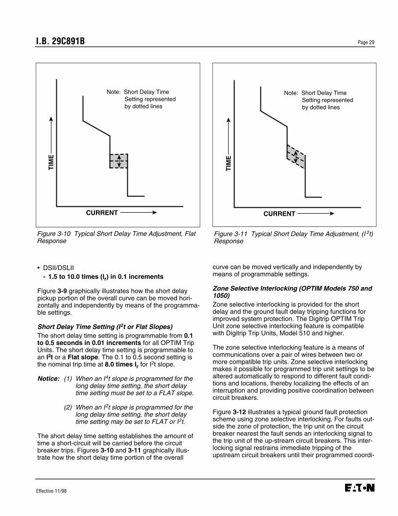
I.B. 29C891B Page 29
Effective 11/98
• DSII/DSLII- 1.5 to 10.0 times (Ir) in 0.1 increments
Figure 3-9 graphically illustrates how the short delaypickup portion of the overall curve can be moved hori-zontally and independently by means of the programma-ble settings.
Short Delay Time Setting (I2t or Flat Slopes)The short delay time setting is programmable from 0.1to 0.5 seconds in 0.01 increments for all OPTIM TripUnits. The short delay time setting is programmable toan I2t or a Flat slope. The 0.1 to 0.5 second setting isthe nominal trip time at 8.0 times Ir for I2t slope.
Notice: (1) When an I4t slope is programmed for thelong delay time setting, the short delaytime setting must be set to a FLAT slope.
(2) When an I2t slope is programmed for thelong delay time setting, the short delaytime setting may be set to FLAT or I2t.
The short delay time setting establishes the amount oftime a short-circuit will be carried before the circuitbreaker trips. Figures 3-10 and 3-11 graphically illus-trate how the short delay time portion of the overall
TIM
E
CURRENT
Note: Short Delay Time Setting represented by dotted lines
Figure 3-11 Typical Short Delay Time Adjustment, (I 2t)Response
TIM
E
CURRENT
Note: Short Delay Time Setting represented by dotted lines
Figure 3-10 Typical Short Delay Time Adjustment, FlatResponse
curve can be moved vertically and independently bymeans of programmable settings.
Zone Selective Interlocking (OPTIM Models 750 and1050)Zone selective interlocking is provided for the shortdelay and the ground fault delay tripping functions forimproved system protection. The Digitrip OPTIM TripUnit zone selective interlocking feature is compatiblewith Digitrip Trip Units, Model 510 and higher.
The zone selective interlocking feature is a means ofcommunications over a pair of wires between two ormore compatible trip units. Zone selective interlockingmakes it possible for programmed trip unit settings to bealtered automatically to respond to different fault condi-tions and locations, thereby localizing the effects of aninterruption and providing positive coordination betweencircuit breakers.
Figure 3-12 illustrates a typical ground fault protectionscheme using zone selective interlocking. For faults out-side the zone of protection, the trip unit on the circuitbreaker nearest the fault sends an interlocking signal tothe trip unit of the up-stream circuit breakers. This inter-locking signal restrains immediate tripping of theupstream circuit breakers until their programmed coordi-
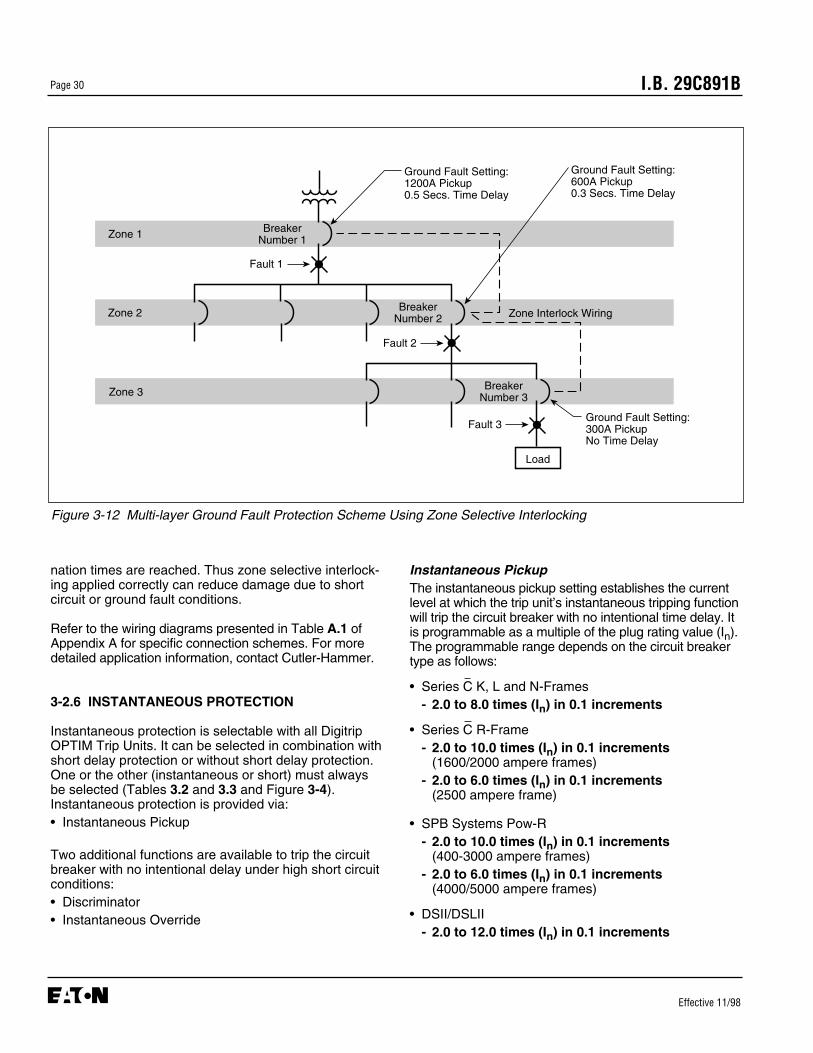
I.B. 29C891BPage 30
Effective 11/98
nation times are reached. Thus zone selective interlock-ing applied correctly can reduce damage due to shortcircuit or ground fault conditions.
Refer to the wiring diagrams presented in Table A.1 ofAppendix A for specific connection schemes. For moredetailed application information, contact Cutler-Hammer.
3-2.6 INSTANTANEOUS PROTECTION
Instantaneous protection is selectable with all DigitripOPTIM Trip Units. It can be selected in combination withshort delay protection or without short delay protection.One or the other (instantaneous or short) must alwaysbe selected (Tables 3.2 and 3.3 and Figure 3-4).Instantaneous protection is provided via:• Instantaneous Pickup
Two additional functions are available to trip the circuitbreaker with no intentional delay under high short circuitconditions:• Discriminator• Instantaneous Override
Instantaneous PickupThe instantaneous pickup setting establishes the currentlevel at which the trip unit’s instantaneous tripping functionwill trip the circuit breaker with no intentional time delay. Itis programmable as a multiple of the plug rating value (In).The programmable range depends on the circuit breakertype as follows:
• Series C K, L and N-Frames- 2.0 to 8.0 times (In) in 0.1 increments
• Series C R-Frame- 2.0 to 10.0 times (In) in 0.1 increments
(1600/2000 ampere frames)- 2.0 to 6.0 times (In) in 0.1 increments
(2500 ampere frame)
• SPB Systems Pow-R- 2.0 to 10.0 times (In) in 0.1 increments
(400-3000 ampere frames)- 2.0 to 6.0 times (In) in 0.1 increments
(4000/5000 ampere frames)
• DSII/DSLII- 2.0 to 12.0 times (In) in 0.1 increments
Load
BreakerNumber 3
BreakerNumber 2
BreakerNumber 1Zone 1
Zone 2
Zone 3
Zone Interlock Wiring
Ground Fault Setting:1200A Pickup0.5 Secs. Time Delay
Ground Fault Setting:600A Pickup0.3 Secs. Time Delay
Ground Fault Setting:300A PickupNo Time Delay
Fault 2
Fault 3
Fault 1
Figure 3-12 Multi-layer Ground Fault Protection Scheme Using Zone Selective Interlocking

I.B. 29C891B Page 31
Effective 11/98
Figure 3-13 graphically illustrates how the instantaneouspickup portion of the overall curve can be moved hori-zontally and independently by means of the programma-ble settings.
DiscriminatorA selectable discriminator circuit is provided on all OPTIMTrip Units. This prevents the circuit breaker from remain-ing closed for the entire duration of the programmed shortdelay time, if the breaker is closed on a high short circuitfault with the instantaneous protective function disabled.
The discriminator circuit (high initial current release) is pre-set at 11 times the rating plug value (11 x In). It is activefor approximately ten cycles following the initial currentflow through the circuit breaker, and is reset whenever theload current falls below 10% of the circuit breaker frame orcurrent sensor rating.
In the event the circuit breaker is not intended to trip outon a circuit whose current could initially be higher than11 x In, it is possible to make the discriminator inactive.If a circuit breaker would close onto a high short-circuitcurrent in this situation, type LS or LSG trip units wouldrely on the short delay protection function. If the faultcurrent exceeds the short-time withstand current capa-bility of the circuit breaker, override protection circuitrywould trip the circuit breaker without delay.
Override (Fixed Instantaneous)An override (fixed instantaneous) circuit is included in allcircuit breakers except DSII and DSLII circuit breakers. Itprotects against a short-circuit current that exceeds theshort-time withstand current capability of the circuitbreaker. The override circuit is set to a value no greaterthan the short time withstand current rating of the circuitbreaker in which the override circuitry is installed. Sincethe specific values vary by circuit breaker type and rat-ing, refer to the applicable time-current curves for thevalue associated with a particular circuit breaker.
3-2.7 GROUND FAULT PROTECTION
Ground fault protection is optional with all OPTIM TripUnits. It can be provided in a number of combinationswith long, short and instantaneous. When ground faulttrip protection is not provided, a ground fault alarm maybe specified, (Tables 3.2 and 3.3 and Figure 3-4). Theavailable trip unit options by circuit breaker type are asfollows:
• Series C K, L and N-Frame and SPB and DSII Circuit Breakers- LSIG (with ground fault trip)- LSIA (with ground fault alarm where “A” may be dis-
abled)
• Model 550 Series C K, L, and N-Frame or all SPB andDSII Circuit Breakers- LSI (without ground fault trip or alarm)
Ground fault protection and other related features are asfollows:• Ground fault alarm• Ground fault pickup• Ground fault delay (I2t Slope)• Ground fault delay (Flat Slope)• Zone selective interlocking (Models 750 and 1050 only)• Ground fault memory
When an OPTIM trip assembly includes ground faultprotection, the distribution system characteristics, suchas system grounding, number of sources, number andlocation of ground points, must be considered. Themanner and location in which the circuit breaker is con-nected to the system should also be considered.
OPTIM units with ground fault protection already haveall the necessary equipment for a 3-phase 3-wiregrounded system. This basic mode for ground faultsensing employs a residual sensing scheme which vec-
TIM
E
CURRENT
Note: Instantaneous Pickup represented by dotted lines
Figure 3-13 Typical Instantaneous Pickup Adjustment
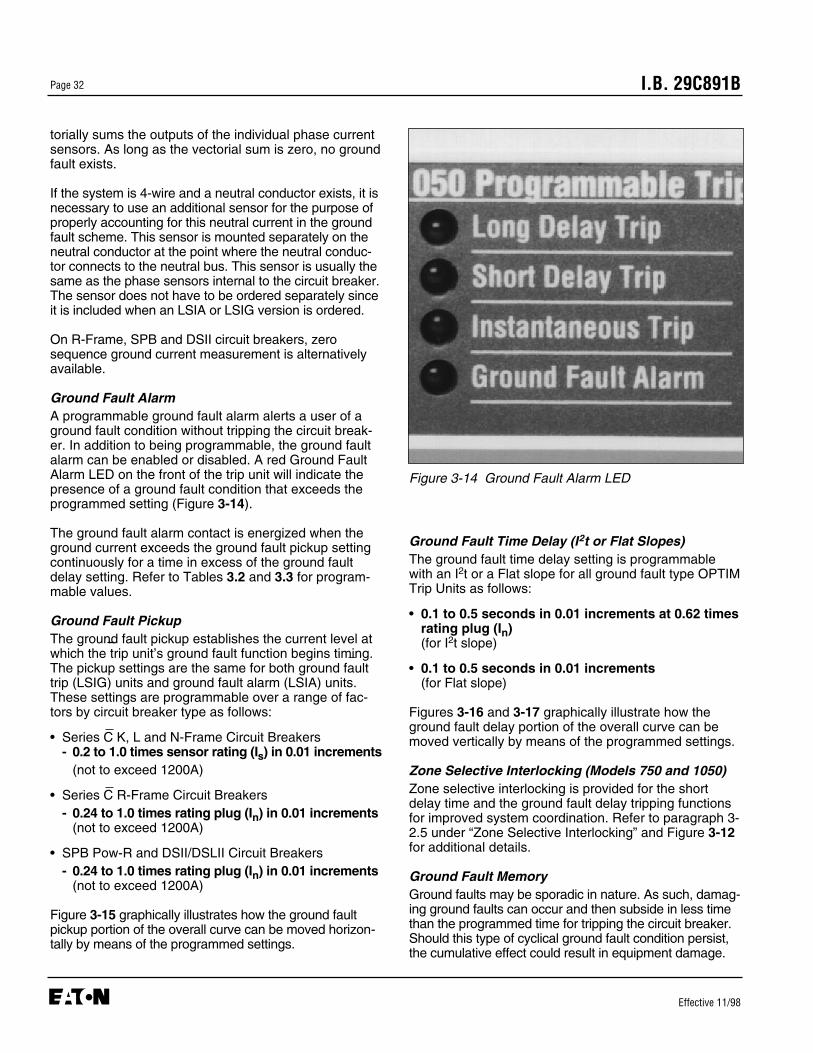
I.B. 29C891BPage 32
Effective 11/98
torially sums the outputs of the individual phase currentsensors. As long as the vectorial sum is zero, no groundfault exists.
If the system is 4-wire and a neutral conductor exists, it isnecessary to use an additional sensor for the purpose ofproperly accounting for this neutral current in the groundfault scheme. This sensor is mounted separately on theneutral conductor at the point where the neutral conduc-tor connects to the neutral bus. This sensor is usually thesame as the phase sensors internal to the circuit breaker.The sensor does not have to be ordered separately sinceit is included when an LSIA or LSIG version is ordered.
On R-Frame, SPB and DSII circuit breakers, zerosequence ground current measurement is alternativelyavailable.
Ground Fault AlarmA programmable ground fault alarm alerts a user of aground fault condition without tripping the circuit break-er. In addition to being programmable, the ground faultalarm can be enabled or disabled. A red Ground FaultAlarm LED on the front of the trip unit will indicate thepresence of a ground fault condition that exceeds theprogrammed setting (Figure 3-14).
The ground fault alarm contact is energized when theground current exceeds the ground fault pickup settingcontinuously for a time in excess of the ground faultdelay setting. Refer to Tables 3.2 and 3.3 for program-mable values.
Ground Fault PickupThe ground fault pickup establishes the current level atwhich the trip unit’s ground fault function begins timing.The pickup settings are the same for both ground faulttrip (LSIG) units and ground fault alarm (LSIA) units.These settings are programmable over a range of fac-tors by circuit breaker type as follows:
• Series C K, L and N-Frame Circuit Breakers - 0.2 to 1.0 times sensor rating (Is) in 0.01 increments
(not to exceed 1200A)
• Series C R-Frame Circuit Breakers - 0.24 to 1.0 times rating plug (In) in 0.01 increments
(not to exceed 1200A)
• SPB Pow-R and DSII/DSLII Circuit Breakers - 0.24 to 1.0 times rating plug (In) in 0.01 increments
(not to exceed 1200A)
Figure 3-15 graphically illustrates how the ground faultpickup portion of the overall curve can be moved horizon-tally by means of the programmed settings.
Ground Fault Time Delay (I2t or Flat Slopes)The ground fault time delay setting is programmablewith an I2t or a Flat slope for all ground fault type OPTIMTrip Units as follows:
• 0.1 to 0.5 seconds in 0.01 increments at 0.62 timesrating plug (In)(for I2t slope)
• 0.1 to 0.5 seconds in 0.01 increments(for Flat slope)
Figures 3-16 and 3-17 graphically illustrate how theground fault delay portion of the overall curve can bemoved vertically by means of the programmed settings.
Zone Selective Interlocking (Models 750 and 1050)Zone selective interlocking is provided for the shortdelay time and the ground fault delay tripping functionsfor improved system coordination. Refer to paragraph 3-2.5 under “Zone Selective Interlocking” and Figure 3-12for additional details.
Ground Fault MemoryGround faults may be sporadic in nature. As such, damag-ing ground faults can occur and then subside in less timethan the programmed time for tripping the circuit breaker.Should this type of cyclical ground fault condition persist,the cumulative effect could result in equipment damage.
Figure 3-14 Ground Fault Alarm LED

I.B. 29C891B Page 33
Effective 11/98
To protect against the the cyclical ground fault conditionjust described, all OPTIM Trip Units with ground faultprotection are provided with a ground fault memoryfunction. The time above pickup is retained in memoryand decays slowly. If another ground fault, high enoughto cause pickup, occurs before the time in memory total-ly decays, the new time adds to the memorized time. Itis this cumulative time that determines whether the cir-cuit breaker will or will not trip on these types of cyclicalground fault conditions.
3-2.8 TIME-CURRENT CURVES
The specific time-current curves applicable to all DigitripOPTIM Trip Units are identified in Appendix A, TableA.1. Contact Cutler-Hammer for a specific curve.
3-3 SYSTEM MONITORING
Digitrip OPTIM Trip Units provide an electrical distributionsystem with superior programmable protection and coor-dination along with advanced warning capabilities, sys-tem diagnostics, monitoring and communications. A sig-nificant part of Digitrip OPTIM’s effectiveness is a result ofits system monitoring capabilities. A comprehensive list of
TIM
E
CURRENT
Note: Ground Fault Delay represented by dotted lines
Figure 3-17 Typical Ground Fault Time DelayAdjustment, (I 2t) Response
TIM
E
CURRENT
Note: Ground Fault Delay represented by dotted lines
Figure 3-16 Typical Ground Fault Time DelayAdjustment, Flat Response
TIM
E
CURRENT
Note: Ground Fault Pickup represented by dotted lines
Figure 3-15 Typical Ground Fault Pickup Adjustment
• Minimum/Maximum magnitudes all monitored currents
Automatic Trip ConditionWhen a system condition results in an automatic trip,the OPTIM Trip Unit monitors and stores in non-volatilememory the reason for the trip and all of the following:• Magnitude phase A, B and C trip currents• Magnitude ground trip current• Magnitude neutral trip current
3-3.3 REMOTE SIGNAL CONTACTS
Series C R-Frame, SPB Pow-R and DSII/DSLIIContacts (Models 750 and 1050)A power relay module, described in paragraph 2-7.2, ismounted internally to Series C R-Frame, SPB Pow-Rand DSII/DSLII circuit breakers to provide control powerand relay contacts for remote signaling.
Series C K, L and N-Frame ContactsThe Series C L and N-Frame breakers provide alarmcontacts by either of two options:
• A remotely mounted ground fault indicator modulemay be hard wired directly to the breaker with Models750 and 1050. This ground fault indicator module pro-vides dedicated alarming contacts for ground faultconditions only. Refer to Table 2.2 for contact ratingsand Table A.1 of Appendix A for the appropriatewiring diagrams.
• The remotely mounted Breaker Interface Module(BIM) has contacts that can be configured to operateunder specific conditions. The signaling of the appro-priate contact operation is done via an IMPACC com-munications link between the breaker and the BreakerInterface Module. Refer to the Breaker InterfaceModule instruction book (I.B. 29C893) for specifics onthe programming and ratings of these contacts.
UNEXPECTED SIGNALS TO CLOSE OR TRIP A CIR-CUIT BREAKER FROM A REMOTE LOCATION VIATHE COMMUNICATIONS NETWORK CAN CAUSEPERSONAL INJURY TO PERSONNEL WORKING INTHE IMMEDIATE VICINITY OF THE CIRCUIT BREAK-ER. PERMISSIVE CONTROL SWITCHES OR OTHERMEANS SHOULD BE PROVIDED LOCALLY AT THE
I.B. 29C891BPage 34
Effective 11/98
WARNING
metered parameters are monitored and then displayedover the OPTIM information system. Local LEDs are usedto indicate a number of conditions and/or operations. TheLEDs are complemented by trip event informationstored in non-volatile memory. Information can beaccessed via the OPTIMizer Hand Held Programmer,Breaker Interface Module, or over the IMPACC System.
System monitoring encompasses the following threebroad categories:• Load Current Monitoring• Power and Energy Monitoring• Power Quality Monitoring
Refer to Tables 3.2 and 3.3 for a general overview ofthe features included in system monitoring. The expect-ed accuracies associated with displayed parameters arealso summarized in Tables 3.2 and 3.3.
3-3.1 DISPLAYS AND LED INDICATORS
All information in the trip unit may be accessed by usingone or more of the following devices:• OPTIMizer Hand Held Programmer (I.B. 29C892)• Breaker Interface Module (I.B. 29C893)• Remote Computer via IMPACC (I.B. 29C890)
For detailed information on the use of a specific device,refer to the instruction book (IB) reference indicated nextto the particular display device.
The trip unit’s information system utilizes front mountedLEDs to indicate a number of trip unit functions, such asmode of trip. Refer to paragraphs 2-4.1 (K, L and N-Frame type trip units) and 2-5.1 (R-Frame, SPB andDSII/DSLII type trip units) for detailed information on theLEDs provided.
3-3.2 NORMAL SERVICE/AUTOMATIC TRIPCURRENT MONITORING
Digitrip OPTIM Trip Units monitor a variety of currents forboth normal service and automatic trip conditions. Thevalue of currents are displayed in amperes by one of thedevices outlined in paragraph 3-3.1.
Normal Service ConditionDuring normal service conditions with the circuit breakerclosed, the OPTIM Trip Unit monitors all of the following:• Present magnitude phase A, B and C currents• Present magnitude ground current or present magni-
tude neutral current
I.B. 29C891B Page 35
Effective 11/98
CIRCUIT BREAKER FOR MAINTENANCE PERSON-NEL TO USE IN CONTROLLING REMOTE CLOSE ORTRIP SIGNALS.
The OPTIM Trip Unit can respond to commands from aremote master computer to trip the circuit breaker remote-ly. In addition, the trip unit can respond to a close com-mand from a remote master computer. Upon receipt of acommand to close the circuit breaker, the reclose relay isenergized for 2 seconds. This contact closure results inthe circuit breaker closing, if the circuit breaker is equippedwith the applicable optional electrical operator or springrelease feature.
3-3.4 POWER AND ENERGY MONITORING
Only Digitrip OPTIM 1050 Trip Units can monitor andthen display power and energy values via theOPTIMizer Hand Held Programmer, Breaker InterfaceModule or a remote computer. The displayed informa-tion is as follows:• Power (Present Demand) in kilowatts (kW)• Peak Demand in kilowatts (kW)• Total Energy in kilowatthours (kWh)• Forward Energy in kilowatthours (kWh)• Reverse Energy in kilowatthours (kWh)
An OPTIM 1050 Trip Unit installed in a Series C K, L orN-Frame Circuit Breaker uses the breaker’s current sen-sors and an externally mounted potential transformermodule to compute power and energy values (Figure 2-14 and paragraph 2-7.1). The values are not non-volatile in memory.
An OPTIM 1050 Trip Unit installed in a Series C R-Frame, SPB Pow-R or DSII/DSLII Circuit Breaker usesthe breaker’s current sensors and a potential trans-former module mounted internally to the circuit breakerto compute power and energy values (Figure 2-14 andparagraph 2-7.2). The values are not non-volatile inmemory.
Power (Present Demand)The power value, also referred to as present demand, isdisplayed in kilowatts (kW). It is a power value averagedover approximately one second.
Peak DemandThe peak demand, displayed in kilowatts (kW), is basedon a sampling window of fifteen (15) minutes. Power isrepeatedly averaged over this interval and the maximum15 minute average is displayed as peak demand. Whenthe trip unit is first energized, there is a delay of 15 min-
utes before the first non-zero value is displayed. Thepeak demand value displayed remains and is notchanged until a higher peak demand is calculated in asubsequent 15 minute window.
EnergyEnergy values are displayed in kilowatthours (kWh), andare a summation of the average power over time. Energyvalues are updated approximately once a second.• Forward energy is based on load current flow from the
“Line” side to the “Load” side of the breaker.• Reverse energy is based on load current flow from the
“Load” side to the “Line” side of the breaker.
3-3.5 POWER QUALITY (HARMONICS)MONITORING
Only Digitrip OPTIM 1050 Trip Units can calculate and dis-play via the OPTIMizer Hand Held Programmer, BreakerInterface Module or a remote computer power qualityinformation. The displayed information is as follows:• THD magnitude of phase A, B and C currents• THD magnitude of ground or neutral currents• % harmonic content phase A, B and C currents (to
27th harmonic)• % harmonic content ground or neutral currents (to
27th harmonic)
THD (Total Harmonic Distortion) indicates the amount ofharmonic current present as a percentage of the RMSvalue of the 60 Hz component of the line current. Thismeasure of distortion can be useful in a troubleshootingmode to detect individual circuit breaker load currentsthat could lead to system overheating problems andsubsequent early equipment failure.
3-3.6 POWER FACTOR
Digitrip OPTIM 1050 Trip Units calculate the systempower factor, which is a unit-less ratio of real power(kW) to apparent power (kVA). The power factor is dis-played by the OPTIMizer Hand Held Programmer,Breaker Interface Module or a remote computer. A pos-itive number indicates a lagging current.
3-4 COMMUNICATIONS
Model 750 and 1050 units and Model 550 with fieldupgrade to IMPACC have the ability to communicateboth information and control signals via the INCOMCommunications Network. INCOM interconnects micro-processor based electrical distribution and control prod-
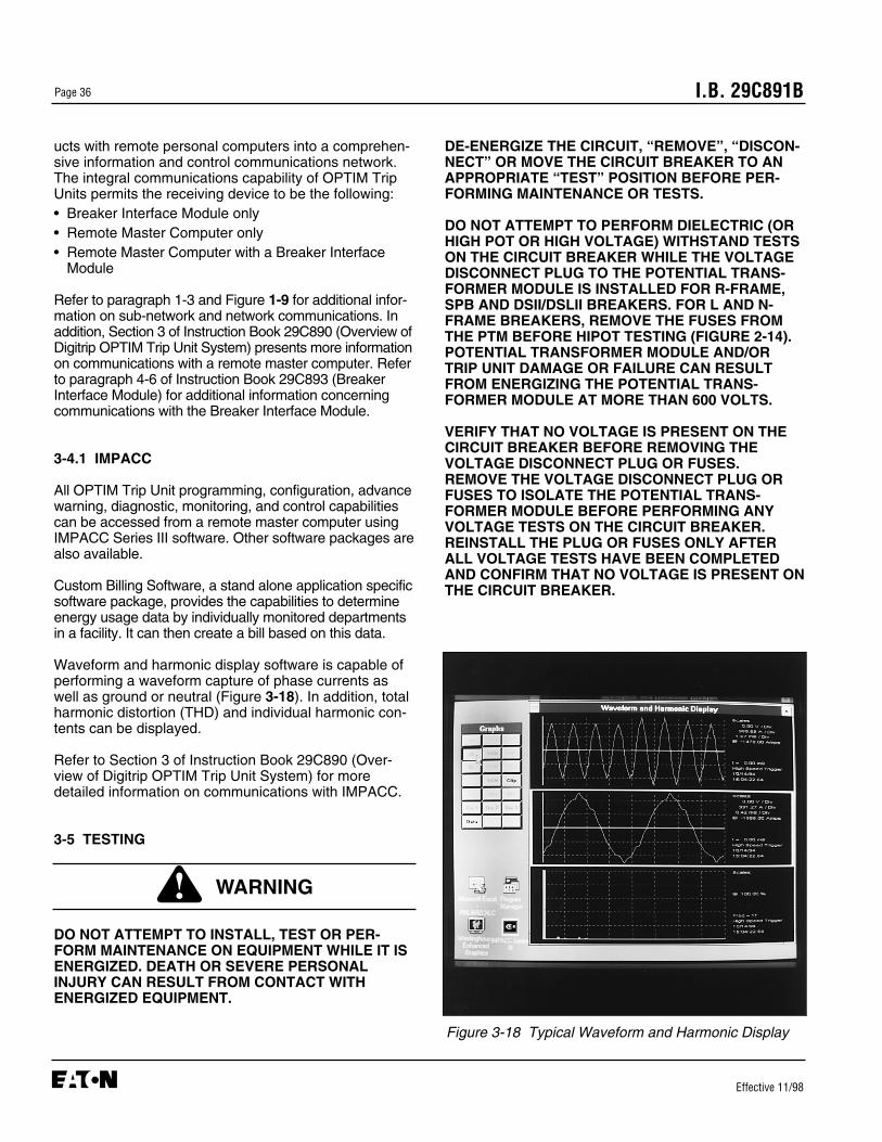
DE-ENERGIZE THE CIRCUIT, “REMOVE”, “DISCON-NECT” OR MOVE THE CIRCUIT BREAKER TO ANAPPROPRIATE “TEST” POSITION BEFORE PER-FORMING MAINTENANCE OR TESTS.
DO NOT ATTEMPT TO PERFORM DIELECTRIC (ORHIGH POT OR HIGH VOLTAGE) WITHSTAND TESTSON THE CIRCUIT BREAKER WHILE THE VOLTAGEDISCONNECT PLUG TO THE POTENTIAL TRANS-FORMER MODULE IS INSTALLED FOR R-FRAME,SPB AND DSII/DSLII BREAKERS. FOR L AND N-FRAME BREAKERS, REMOVE THE FUSES FROMTHE PTM BEFORE HIPOT TESTING (FIGURE 2-14).POTENTIAL TRANSFORMER MODULE AND/ORTRIP UNIT DAMAGE OR FAILURE CAN RESULTFROM ENERGIZING THE POTENTIAL TRANS-FORMER MODULE AT MORE THAN 600 VOLTS.
VERIFY THAT NO VOLTAGE IS PRESENT ON THECIRCUIT BREAKER BEFORE REMOVING THEVOLTAGE DISCONNECT PLUG OR FUSES.REMOVE THE VOLTAGE DISCONNECT PLUG ORFUSES TO ISOLATE THE POTENTIAL TRANS-FORMER MODULE BEFORE PERFORMING ANYVOLTAGE TESTS ON THE CIRCUIT BREAKER.REINSTALL THE PLUG OR FUSES ONLY AFTERALL VOLTAGE TESTS HAVE BEEN COMPLETEDAND CONFIRM THAT NO VOLTAGE IS PRESENT ONTHE CIRCUIT BREAKER.
I.B. 29C891BPage 36
Effective 11/98
Figure 3-18 Typical Waveform and Harmonic Display
ucts with remote personal computers into a comprehen-sive information and control communications network.The integral communications capability of OPTIM TripUnits permits the receiving device to be the following:• Breaker Interface Module only• Remote Master Computer only• Remote Master Computer with a Breaker Interface
Module
Refer to paragraph 1-3 and Figure 1-9 for additional infor-mation on sub-network and network communications. Inaddition, Section 3 of Instruction Book 29C890 (Overview ofDigitrip OPTIM Trip Unit System) presents more informationon communications with a remote master computer. Referto paragraph 4-6 of Instruction Book 29C893 (BreakerInterface Module) for additional information concerningcommunications with the Breaker Interface Module.
3-4.1 IMPACC
All OPTIM Trip Unit programming, configuration, advancewarning, diagnostic, monitoring, and control capabilitiescan be accessed from a remote master computer usingIMPACC Series III software. Other software packages arealso available.
Custom Billing Software, a stand alone application specificsoftware package, provides the capabilities to determineenergy usage data by individually monitored departmentsin a facility. It can then create a bill based on this data.
Waveform and harmonic display software is capable ofperforming a waveform capture of phase currents aswell as ground or neutral (Figure 3-18). In addition, totalharmonic distortion (THD) and individual harmonic con-tents can be displayed.
Refer to Section 3 of Instruction Book 29C890 (Over-view of Digitrip OPTIM Trip Unit System) for moredetailed information on communications with IMPACC.
3-5 TESTING
DO NOT ATTEMPT TO INSTALL, TEST OR PER-FORM MAINTENANCE ON EQUIPMENT WHILE IT ISENERGIZED. DEATH OR SEVERE PERSONALINJURY CAN RESULT FROM CONTACT WITHENERGIZED EQUIPMENT.
WARNING
I.B. 29C891B Page 37
Effective 11/98
TESTING A CIRCUIT BREAKER UNDER TRIP CON-DITIONS WHILE IN SERVICE AND CARRYING LOADCURRENT, WHETHER DONE BY LOCAL ORREMOTE MEANS, IS NOT RECOMMENDED.
ANY TRIPPING OPERATION WILL CAUSE A DIS-RUPTION IN SERVICE AND POSSIBLE PERSONALINJURY RESULTING FROM UNNECESSARYSWITCHING OF CONNECTED EQUIPMENT.
TESTING OF A CIRCUIT BREAKER THAT RESULTSIN TRIPPING OF THE CIRCUIT BREAKER SHOULDBE DONE ONLY WITH THE CIRCUIT BREAKER IN A“TEST” OR “DISCONNECTED” CELL POSITION, ORWHILE REMOVED TO A TEST BENCH.
Digitrip OPTIM 550, 750 and 1050 Trip Units have a testcapability. “No-Trip” and “Trip” tests can be performedusing any of the following:• OPTIMizer Hand Held Programmer
(Figure 1-6 and I.B. 29C892))• Breaker Interface Module (Model 550 with IMPACC kit)
(Figure 1-7 and I.B. 29C893)• Remote computer/IMPACC software
(Figure 1-8 and I.B. 29C890)
Refer to the applicable instruction book for informationon performing tests using one of the outlined methods.
3-5.1 SECONDARY INJECTION TESTING
A test current may be injected into the secondary trans-former terminals (5A level) for DSII/DSLII circuit break-ers only. For K, L, N and R-Frame and SPB Pow-R cir-cuit breakers, these terminals are either not present ornot accessible.
DSII and DSLII Type Power Circuit Breakers have afield test kit receptacle that can be used for secondaryinjection testing to test OPTIM Trip Units. With theAuxiliary Power Module installed, the circuit breaker canbe tested using secondary currents provided by anAmptector Trip Unit Test Kit. Refer to supplementalDSII/DSLII Circuit Breaker information in Table A.1 ofAppendix A for secondary injection testing details.
3-5.2 WHEN TO TEST
Tests can be performed with the circuit breaker in the“Connected” position while carrying load current.
However, as stated in the CAUTION at the beginning ofthis section, good practice will limit circuit breaker in-ser-vice “Trip” tests to maintenance periods during times ofminimum load conditions. Testing is recommended withthe circuit breaker out of its cell or in an appropriate“Test,” “Disconnected” or “Removed” cell positions.
Notice: Since time-current settings are based ondesired system coordination and protectionschemes, the protection settings selected andprogrammed should not be altered during oras a part of any routine test sequence.
3-5.3 CONDUCTING TESTS
CIRCUIT BREAKER OPERATING MECHANISMSOPEN AND CLOSE THE MOVING PARTS QUICKLYAND WITH VERY HIGH ENERGY. TOUCHING THEMOVING PARTS DURING OPERATION COULDRESULT IN SERIOUS BODILY INJURY. KEEPCLOTHING AND ALL PARTS OF THE BODY WELLAWAY FROM ALL MOVING PARTS. IN ADDITION,FOLLOW ALL INSTRUCTIONS GIVEN FOR TESTINGA SPECIFIC TYPE CIRCUIT BREAKER IN THEAPPROPRIATE INSTRUCTIONAL MATERIAL FORTHAT CIRCUIT BREAKER.
Notice: Testing will not be permitted to proceed if thereis greater than the following per unit of currentflowing on a phase or ground circuit:• No-Trip Test
- >1.0 phase or 0.2 ground• Trip Test
- >0.5 phase or 0.2 ground
The maximum permitted current value can bedetermined by multiplying the appropriate perunit value times the ampere rating of theinstalled rating plug.
The Digitrip OPTIM test capability can be used to per-form No-Trip and Trip tests. All testing requires controlpower, except for No-Trip testing with the OPTIMizerHand Held Programmer. This testing can be accom-plished using the internal battery power of the OPTIM-izer. Control power, depending on the testing method,can be supplied by an Auxiliary Power Module or by aux-iliary power supplied to the circuit breaker (Figure 3-19and paragraph 2-7). The auxiliary power is required toactivate the breaker’s flux transfer shunt trip.
CAUTION
WARNING

I.B. 29C891BPage 38
Effective 11/98
Notice: Basic protection functions are not affected dur-ing the performance of testing procedures.
Before starting a test sequence, check to be sure that theOperational Status LED on the face of the OPTIM TripUnit is blinking at approximately a 1 second on-off dutycycle, indicating power is being applied to the trip unit andit is functioning normally (Figures 2-4 and 2-10). In theevent that the LED is not blinking at this rate, check to besure that control power is available or the battery in theOPTIMizer Hand Held Programmer is good.
When performing tests, keep in mind that different com-binations of protection features can contribute to theresults of the testing, and be the cause of unexpectedtripping actions. Long delay thermal memory orground fault memory, for example, could result in anunexpected tripping action. Paragraphs 3-2.4 and 3-2.7 should be reviewed if there are any questions.
Keep in mind that the Trip Reset pushbutton located onthe front of the trip unit will have to be pushed to resettrip unit conditions after a test is completed that causesthe circuit breaker to trip and LED indicators to be lit(Figures 2-4 and 2-10).
3-5.4 PERFORMANCE TESTING FOR GROUNDFAULT TRIP UNITS
Code RequirementsThe National Electrical Code under Article 230-95-Crequires that any ground fault protection system be per-formance tested when first installed. The test shall beconducted in accordance with approved instructionsprovided with the equipment. A written record of this testshall be made and available to the authority havinginspection jurisdiction.
Standards RequirementsAs a follow-up to the basic performance requirementsstipulated by the N.E.C. in Section 6.2.1, UL StandardsNo. 1053 requires that certain minimum instructionsmust accompany each ground fault protection system.The following article plus the test record form illustratedin Figure 3-21 are intended to satisfy this requirement.
General Test InstructionsThe interconnected system shall be evaluated in accor-dance with the equipment assembler’s detailed instruc-tions by qualified personnel.
The polarity of the neutral sensor connections, if used,must agree with the equipment assembler’s detailedinstructions to avoid improper operations followingapparently correct simulated test operations. Where aquestion exists, consult the specifying engineer and/orequipment assembler.
The grounding point of the system shall be verified todetermine that ground paths do not exist that wouldbypass the sensors. The use of high voltage testers andresistance bridges may be used.
Figure 3-19 Auxiliary Power Module

I.B. 29C891B Page 39
Effective 11/98
GROUND FAULT TEST RECORD FORM
Ground Fault Test Record should be Retained by Those in Charge of the Building’s ElectricalInstallation in order to be available to the Authority having Jurisdiction.
TEST DATE CIRCUIT BREAKER RESULTSNUMBER
Figure 3-21 Typical Performance Test Record Form

I.B. 29C891BPage 40
Effective 11/98
4-3.1 BEFORE POWER APPLICATION
STARTUP PROCEDURES MUST BE PERFORMEDBY QUALIFIED PERSONNEL WHO ARE FAMILIARWITH DIGITRIP OPTIM TRIP UNITS, THE LOW VOLT-AGE CIRCUIT BREAKERS IN WHICH THEY AREAPPLIED, AND ALL OTHER ASSOCIATED ELECTRI-CAL AND/OR MECHANICAL EQUIPMENT. FAILURETO OBSERVE THIS WARNING COULD RESULT INPERSONAL INJURY, DEATH AND/OR EQUIPMENTDAMAGE.
After all installation wiring is complete and before poweris applied to any equipment, perform the following steps:
Step 1: Verify that all wiring is correct as shown on theapplicable wiring diagrams and/or wiring plandrawings.
Step 2: Remove and discard the factory default set-tings label covering the programming port oneach trip unit.
Step 3: Verify that a correct rating plug is securelyinstalled in each trip unit.
Notice: Mechanical rejection means will prevent theinstallation of a rating plug in a trip unit forwhich it was not intended.
Step 4: Press the battery test/check pushbutton. Theassociated green LED should light. Refer toparagraph 5-4.1 for specific assistance.
Step 5: Use the OPTIMizer Hand Held Programmer toassign unique device addresses and selectbaud rates. Refer to the OPTIMizer Hand HeldProgrammer Instruction Book 29C892 for spe-cific assistance.
Notice: • For applications with Breaker Interface Modules- the acceptable address ranges for trip units
are 1-32 (HEXADECIMAL).• For applications with a remote PC and no
Breaker Interface Modules present- the acceptable address ranges for trip units
are 1-FFE (HEXADECIMAL).
Step 6: Use the OPTIMizer Hand Held Programmer tocheck and adjust, if necessary, trip unit pickup
SECTION 4: STARTUP AND TESTING
4-1 INTRODUCTION
This section addresses those procedures associatedwith the startup and testing of installed Digitrip OPTIMTrip Units. As a minimum, the OPTIMizer Hand HeldProgrammer Instruction Book 29C892 along with thisinstruction book will be required to complete the systemsetup, program the trip unit, and functionally test the tripunit and circuit breaker.
4-2 WIRING
This section references wiring diagrams that are associ-ated with specific circuit breakers and their installedDigitrip OPTIM Trip Units. All wiring must conform toapplicable federal, state and local codes.
4-2.1 WIRING DIAGRAMS
Specific wiring diagrams (connection diagrams) presentall the required direct connections associated with a par-ticular circuit breaker type with an installed DigitripOPTIM Trip Unit. Wiring diagrams are identified by cir-cuit breaker type in Appendix A. These wiring diagramsare required to create an accurate wiring plan drawing.
4-2.2 WIRING PLAN DRAWING
External wiring associated with a circuit breaker and itsinstalled Digitrip OPTIM Trip Unit must follow a suitablewiring plan drawing. The phrase “wiring plan drawing”refers to the drawing or drawings made for a specificapplication. All electrical connections between the circuitbreaker and external equipment are described. Thisdrawing is the responsibility of the OEM or user.
4-2.3 NETWORK WIRING DIAGRAM
A network wiring diagram would also be helpful for sub-network and network systems. This diagram is theresponsibility of the OEM or user. Refer to Figure 4-1 toreview a typical network wiring diagram.
4-3 INITIAL STARTUP
This information is intended to be used when applyingcontrol power to a system, including the trip units. It isespecially important during the first power application.
WARNING
I.B. 29C891B Page 41
Effective 11/98
and time settings in keeping with system coor-dination requirements.
Step 7: If the system is utilizing one or more BreakerInterface Modules or is network connectedthrough IMPACC, verification of circuit breakeraddresses and protective/ monitoring criteriacan be accomplished using a Breaker InterfaceModule or remote computer. As required, referto Instruction Book 29C893 to review the useof the Breaker Interface Module or InstructionBook 29C890 for an overview of the completeDigitrip OPTIM Trip Unit System, includingIMPACC communications.
4-3.2 INITIAL POWER APPLICATION
a. Apply system power and observe individual trip unitsand/or other system monitoring devices, such as theBreaker Interface Module or remote computer.
b. The green Unit Status LED should blink if either(Figures 2-4 and 2-10):
1. The circuit breaker current in at least one phase exceeds 20% of the installed rating plug value
(or)2. Auxiliary power is supplied to the circuit
breaker.
The red transmit LED will blink whenever the trip unitis communicating on the IMPACC Network.
c. Should what appears to be a problem occur, refer tothe Troubleshooting Guide (Table 5.1) of this manu-al. For additional troubleshooting assistance, refer tothe Troubleshooting Guides in the OPTIMizer HandHeld Programmer and/or the Breaker InterfaceModule instruction books (I.B. 29C892 and I.B.29C893 respectively). For further assistance, consultCutler-Hammer.
4-4 TESTING
Section 3-5 provides details associated with testingOPTIM Trip Units and circuit breakers equipped withOPTIM Trip Units. It is recommended that Section 3-5be read first. In addition, follow the testing instructionspresented in the OPTIMizer Hand Held Programmerinstruction book (I.B. 29C892) or the Breaker InterfaceModule instruction book (I.B. 29C893). Testing can alsobe performed using a remote computer over theIMPACC system.
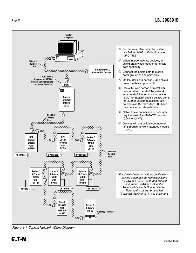
I.B. 29C891BPage 42
Effective 11/98
Figure 4-1 Typical Network Wiring Diagram
MasterComputer
BreakerInterfaceModule
ShieldedTwistedPair
SPBCircuit Breaker
with OPTIM
DSIICircuitBreaker
withOPTIM
Series CR-Frame
MCCBwith
OPTIM
To Other IMPACCCompatible Devices
PONI
OPTIMizer
Series CN-Frame
MCCBwith
OPTIM
Series CL-FrameMCCBwith
OPTIM
Circuit Breaker
with RMS 810
or 910
Series CF-FrameMCCB
ES
IQ Energy Sentinel
ShieldedTwistedPair
PONI Module(Required for IMPACC
Network Communicationsto Master Computer)
ShieldedTwisted
Pair
➁ ➂
➃
OPTIMizer ➀➀ OPTIMizer ➀
OPTIMizer ➀OPTIMizer ➀
Series CK-Frame
MCCBwith
OPTIM
OPTIMizer ➀
➀ For network interconnection cable, use Belden 9463 or Cutler-HammerIMPCABLE.
➁ When interconnecting devices, tieshield drain wires together for shieldpath continuity.
➂ Connect the shield path to a solidearth ground at one point only.
➃ On last device in network, tape shielddrain wire back upon cable.
➄ Use a 1/2 watt carbon or metal filmresistor at each end of the network as an end of line termination resistor(EOLTR). EOLTR should be 100 ohmsfor 9600 baud communication rate networks or 150 ohms for 1200 baudcommunication rate networks.
➅ Network interconnection to computerrequires use of an IMPACC master(CONI or MINT).
➆ Devices without built-in communica-tions require network interface module(PONI).
For detailed network wiring specifications,call the automatic fax retrieval system(FRED) at 412/494-3745 and request
document 17513 or contact the Advanced Products Support Center.
Refer to the paragraph entitled “Technical Assistance” in this document.
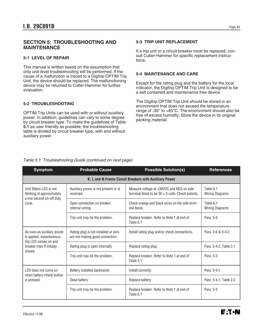
I.B. 29C891B Page 43
Effective 11/98
SECTION 5: TROUBLESHOOTING ANDMAINTENANCE
5-1 LEVEL OF REPAIR
This manual is written based on the assumption thatonly unit-level troubleshooting will be performed. If thecause of a malfunction is traced to a Digitrip OPTIM TripUnit, the device should be replaced. The malfunctioningdevice may be returned to Cutler-Hammer for furtherevaluation.
5-2 TROUBLESHOOTING
OPTIM Trip Units can be used with or without auxiliarypower. In addition, guidelines can vary to some degreeby circuit breaker type. To make the guidelines of Table5.1 as user friendly as possible, the troubleshootingtable is divided by circuit breaker type, with and withoutauxiliary power.
5-3 TRIP UNIT REPLACEMENT
If a trip unit or a circuit breaker must be replaced, con-sult Cutler-Hammer for specific replacement instruc-tions.
5-4 MAINTENANCE AND CARE
Except for the rating plug and the battery for the localindicator, the Digitrip OPTIM Trip Unit is designed to bea self contained and maintenance free device.
The Digitrip OPTIM Trip Unit should be stored in anenvironment that does not exceed the temperaturerange of -30° to +85°C. The environment should also befree of excess humidity. Store the device in its originalpacking material.
K, L and N-Frame Circuit Breakers with Auxiliary Power
Unit Status LED is not Auxiliary power is not present or is Measure voltage at +30VDC and NEG on side Table A.1blinking at approximately reversed. terminal block to be 30 ± 3 volts. Check polarity. Wiring Diagramsa one second on-off dutycycle. Open connection on breaker Check orange and black wires on the side term- Table A.1
internal wiring. inal block. Wiring Diagrams
Trip unit may be the problem. Replace breaker. Refer to Note 1 at end of Para. 5-3Table 5.1
As soon as auxiliary power Rating plug is not installed or pins Install rating plug and/or check connections. Para. 2-6 & 5-4.2is applied, instantaneous are not making good connection.trip LED comes on and breaker trips if initially Rating plug is open internally Replace rating plug Para. 5-4.2, Table 2.1 closed.
Trip unit may be the problem. Replace breaker. Refer to Note 1 at end of Para. 5-3Table 5.1
LED does not come on Battery installed backwards Install correctly Para. 5-4.1when battery check buttonis pressed. Dead battery Replace battery Para. 5-4.1, Table 2.2
Trip unit may be the problem. Replace breaker. Refer to Note 1 at end of Para. 5-3Table 5.1
Table 5.1 Troubleshooting Guide (continued on next page)
Symptom Probable Cause Possible Solution(s) References

Power values are grossly Connections from PT Module to Check connections Table A.1in error (1050 Trip Units breaker not made or are incorrect. Wiring Diagramsonly).
Line frequency incorrect Verify operating frequency with OPTIMizer. I.B. 29C892, Para. 3-6
Trip unit may be the problem Replace breaker. Refer to Note 1 at end of Para. 5-3Table 5.1
“Connection Failure” FIRST DISCONNECT AUXILIARY POWER TEMPORARILY, THEN CHECK THE FOLLOWING:displayed when OPTIMizer is plugged in. OPTIMizer not working or cord not Verify OPTIMizer operation on another breaker. I.B. 29C892
properly plugged into OPTIMizer. Para. 2-2.2 & 3-2
Cord not properly plugged into Check connection. If unit status LED is blinking, Para. 2-4.1breaker. connection is OK.
Rating plug is not installed or is Instantaneous LED will be on. Install rating plug Para. 2-6 & 5-4.2loose. and/or check for loose connections.
Rating plug is open internally Instantaneous LED will be on. Replace rating Para. 5-4.2, Table 2.1plug.
Trip unit may be the problem. Replace breaker. Refer to Note 1 at end of Para. 5-3Table 5.1
RECONNECT AUXILIARY POWER
BIM will not communicate Breaker address is > 32 (HEX) Check address with OPTIMizer and change as I.B. 29C892with trip unit. required. Para. 3-5.1
No auxiliary power If possible, open breaker or reduce breaker Symptom: “Unitcurrent to <20% of frame rating. Then, check Status LED is notthat unit status LED is blinking. If not, see first blinking.”symptom in this table.
Rating plug is not installed or is Instantaneous LED will be on. Install rating plug Para. 2-6 & 5-4.2loose. and/or check for loose connections.
Rating plug is open internally Instantaneous LED will be on. Replace rating Para. 5-4.2, Table 2.1plug.
Open INCOM connection Check INCOM connections on side terminal Table A.1block. The transmit LED should flash when there Wiring Diagramsis communication. With INCOM connector unplugged, the resistance “looking into” theINCOM terminals should be approximately 2.5ohms.
Trip unit may be the problem. Replace breaker. Refer to Note 1 at end of Para. 5-3Table 5.1
I.B. 29C891BPage 44
Effective 11/98
Table 5.1 Troubleshooting Guide (continued from previous page)
Symptom Probable Cause Possible Solution(s) References
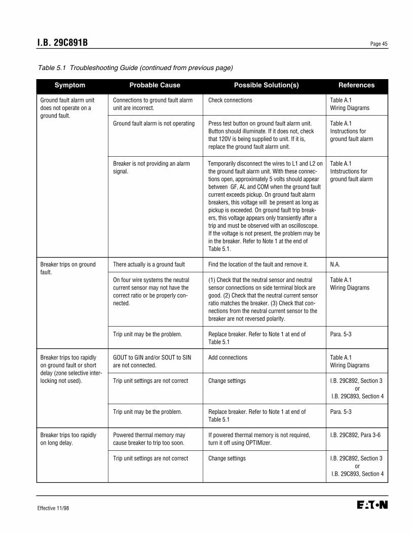
Ground fault alarm unit Connections to ground fault alarm Check connections Table A.1does not operate on a unit are incorrect. Wiring Diagramsground fault.
Ground fault alarm is not operating Press test button on ground fault alarm unit. Table A.1Button should illuminate. If it does not, check Instructions for that 120V is being supplied to unit. If it is, ground fault alarmreplace the ground fault alarm unit.
Breaker is not providing an alarm Temporarily disconnect the wires to L1 and L2 on Table A.1signal. the ground fault alarm unit. With these connec- Intstructions for
tions open, approximately 5 volts should appear ground fault alarmbetween GF, AL and COM when the ground fault current exceeds pickup. On ground fault alarm breakers, this voltage will be present as long as pickup is exceeded. On ground fault trip break-ers, this voltage appears only transiently after a trip and must be observed with an oscilloscope. If the voltage is not present, the problem may bein the breaker. Refer to Note 1 at the end ofTable 5.1.
Breaker trips on ground There actually is a ground fault Find the location of the fault and remove it. N.A.fault.
On four wire systems the neutral (1) Check that the neutral sensor and neutral Table A.1current sensor may not have the sensor connections on side terminal block are Wiring Diagramscorrect ratio or be properly con- good. (2) Check that the neutral current sensor nected. ratio matches the breaker. (3) Check that con-
nections from the neutral current sensor to the breaker are not reversed polarity.
Trip unit may be the problem. Replace breaker. Refer to Note 1 at end of Para. 5-3Table 5.1
Breaker trips too rapidly GOUT to GIN and/or SOUT to SIN Add connections Table A.1on ground fault or short are not connected. Wiring Diagramsdelay (zone selective inter-locking not used). Trip unit settings are not correct Change settings I.B. 29C892, Section 3
or I.B. 29C893, Section 4
Trip unit may be the problem. Replace breaker. Refer to Note 1 at end of Para. 5-3Table 5.1
Breaker trips too rapidly Powered thermal memory may If powered thermal memory is not required, I.B. 29C892, Para 3-6on long delay. cause breaker to trip too soon. turn it off using OPTIMizer.
Trip unit settings are not correct Change settings I.B. 29C892, Section 3or
I.B. 29C893, Section 4
I.B. 29C891B Page 45
Effective 11/98
Table 5.1 Troubleshooting Guide (continued from previous page)
Symptom Probable Cause Possible Solution(s) References

I.B. 29C891BPage 46
Effective 11/98
Trip unit may be the problem. Replace breaker. Refer to Note 1 at end of Para. 5-3Table 5.1.
Zone selective interlockingon ground fault and/or See directions for checking zone selective interlocking Appendix Bshort delay does not work.
Communication over No auxiliary power Check that the Unit Status LED is blinking. If not, Symptom: “UnitIMPACC is not working. see first symptom in this table. Status LED is not(Direct with BIM not involved) blinking.”
Open INCOM connection Check INCOM connections on side terminal Table A.1block. The transmit LED should flash when there Wiring Diagramsis communication. With INCOM connector un-plugged, the resistance “looking into” the INCOMterminals should be approximately 2.5 ohms.
Trip unit may be the problem. Replace breaker. Refer to Note 1 at end of Para. 5-3Table 5.1.
K, L and N-Frame Circuit Breakers without Auxiliary Power
Unit Status LED is not Current thru breaker is < 20% of No problem. Status LED will not operate with N.A.blinking at approxi- frame rating. breaker currents < 20% of frame rating.mately a one secondon-off duty cycle Trip unit may be the problem Replace breaker. Refer to Note 1 at end of Para. 5-3
Table 5.1.
As soon as current starts Rating plug is not installed or is Install rating plug and/or check for loose Para 2-6 & 5-4.2to flow thru the breaker, loose. connections.it trips and the instantan-eous trip LED comes on. Rating plug is open internally Replace rating plug Para. 5-4.2, Table 2.1
Trip unit may be the problem. Replace breaker. Refer to Note 1 at end of Para. 5-3Table 5.1.
LED does not come on Battery installed backwards Install correctly Para. 5-4.1when battery checkbutton is pressed. Dead battery Replace battery Para. 5-4.1, Table 2.2
Trip unit may be the problem Replace breaker. Refer to Note 1 at end of Para. 5-3Table 5.1.
Power values are grossly Connections from PT Module to Check connections Table A.1in error (1050 trip units breaker not made or are incorrect. Wiring Diagramsonly).
Frequency incorrect Verify operating frequency with OPTIMizer I.B. 29C892, Para 3-6
Trip unit may be the problem. Replace breaker. Refer to Note 1 at end of Para. 5-3Table 5.1.
Table 5.1 Troubleshooting Guide (continued from previous page)
Symptom Probable Cause Possible Solution(s) References

“Connection Failure” when OPTIMizer not working or cord not Verify OPTIMizer operation on another breaker. I.B. 29C892OPTIMizer is plugged in. properly plugged into OPTIMizer. Para. 2-2.2 & 3-2
Cord not properly plugged into Check connection. If unit status LED is blinking, Para. 2-4.1 breaker. connection is OK.
Rating plug is not installed or is Instantaneous LED will be on. Install rating plug Para. 2-6 & 5-4.2loose. and/or check for loose connections.
Rating plug is open internally Replace rating plug Para. 5-4.2, Table 2.1
Trip unit may be the problem. Replace breaker. Refer to Note 1 at end of Para. 5-3Table 5.1.
Ground fault alarm unit Connections to ground fault alarm Check connections Table A.1does not operate on a unit are incorrect. Wiring Diagramsground fault.
Ground fault alarm is not operating Press test button on ground fault alarm unit. Table A.1Button should illuminate. If it does not, check Instructions for that 120V is being supplied to unit. If it is, ground fault alarmreplace the ground fault alarm unit.
Breaker is not providing an alarm Temporarily disconnect the wires to L1 and L2 Table A.1on the ground fault alarm unit. With these con- Instructions fornections open, approximately 5 volts should ground fault alarmappear between GF, AL and COM when the and wiring diagramsground fault current exceeds pickup. On groundfault alarm breakers, this voltage will be present as long as pickup is exceeded. On ground faulttrip breakers, this voltage appears only trans-iently after a trip and must be observed with an oscilloscope. If the voltage is not present, the problem may be in the breaker. Refer to Note 1at the end of Table 5.1.
Breaker trips on ground There actually is a ground fault Check circuit to find the location of the fault. N.A.fault.
On four wire systems the neutral (1) Check neutral sensor and neutral sensor Table A.1current sensor may not have the connections on side terminal block are good. Wiring Diagramscorrect ratio or be properly con- (2) Check that the neutral current sensor ratio nected. matches the breaker. (3) Check that connections
from the neutral current sensor to the breaker are not reversed.
Trip unit may be the problem. Replace breaker. Refer to Note 1 at end of Para. 5-3Table 5.1.
I.B. 29C891B Page 47
Effective 11/98
Table 5.1 Troubleshooting Guide (continued from previous page)
Symptom Probable Cause Possible Solution(s) References

I.B. 29C891BPage 48
Effective 11/98
Table 5.1 Troubleshooting Guide (continued from previous page)
Symptom Probable Cause Possible Solution(s) References
Breaker trips too rapidly GOUT to GIN and/or SOUT to SIN Add connections Table A.1on ground fault or short are not shorted. Wiring Diagramsdelay (zone selectiveinterlocking not used). Trip unit settings are not correct. Change settings I.B. 29C892, Section 3
orI.B. 29C893, Section 4
Trip unit may be the problem. Replace breaker. Refer to Note 1 at end of Para. 5-3Table 5.1.
Breaker trips too rapidly on Unpowered thermal memory may If unpowered thermal is not required, turn it off I.B. 29C892, Para. 3-6long delay. cause breaker to trip too soon. using OPTIMizer.
Trip unit settings are not correct. Change settings I.B. 29C892, Section 3or
I.B. 29C893, Section 4
Trip unit may be the problem. Replace breaker. Refer to Note 1 at end of Para. 5-3Table 5.1.
Zone selective interlockingon ground fault and/or See directions for checking zone selective interlocking Appendix Bshort delay does not work.
R-Frame, SPB Pow-R and DSII/DSLII Circuit Breakers with Auxiliary Power
Unit status LED is not No voltage or incorrect voltage input. Measure voltage at terminals C9 - C10 on RD Table A.1blinking. and SPB breakers or 5 - 6 on DSII breakers, Wiring Diagrams
should be 115V 60Hz or 230V 50Hz per breakerlabel.
Trip unit may be the problem. Replace trip unit Para. 5-3
As soon as auxiliary power Rating plug not installed or pins not Install rating plug and/or check for loose con- Para. 2-6 & 5-4.2is applied, instantaneous making good connection. nections.trip LED comes on. Note: Breaker cannot be closed if
rating plug is not installed.
Rating plug is open internally Replace rating plug Para. 5-4.2, Table 2.1
Trip unit may be the problem. Replace trip unit Para. 5-3
LED does not come on Battery installed backwards Install correctly Para. 5-4.1when battery check button inside rating plug is Dead battery Replace battery Para. 5-4.1, Table 2.2pressed.
Bad rating plug Replace rating plug Para. 5-4.2, Table 2.1

Power values are grossly No voltage input to trip unit. Check PT disconnect plug is installed.in error. (1050 Trip Unitsonly) Frequency incorrect Verify operating frequency with OPTIMizer. I.B. 29C892, Para. 3-6
Trip unit may be the problem. Replace trip unit Para. 5-3
“Connection Failure” when FIRST DISCONNECT VOLTAGE SUPPLY TO TERMINALS C9 AND C10 ON RD AND SPB OPTIMizer is plugged in. BREAKERS OR 5 AND 6 ON DSII BREAKERS TEMPORARILY. (Place drawout breakers
in disconnect position which will remove voltage supply)
OPTIMizer not working or cord not Verify OPTIMizer operation on another breaker. I.B. 29C892properly plugged into OPTIMizer. Para. 2-2.2 & 3-2
Cord not properly plugged into Check connection. If unit status LED is blinking, Para. 2-5.1breaker. connection is OK.
Rating plug is not installed or is Instantaneous LED will be on. Install rating plug Para. 2-6 & 5-4.2loose. and/or check for loose connections.
Rating plug is open internally Instantaneous LED will be on. Replace rating Para. 5-4.2, Table 2.1plug.
Trip unit may be the problem. Replace trip unit Para. 5-3
RECONNECT VOLTAGE SUPPLY
BIM will not communicate Breaker address is > 32 (HEX) Check address with OPTIMizer and change as I.B. 29C892with trip unit. required. Para. 3-5.1
No auxiliary power If possible, open breaker or reduce breaker Symptom: “Unitcurrent <20% of frame rating. Then check that Status LED is not unit status LED is blinking. If not, see first blinking.”symptom in this portion of the table.
Rating plug is not installed Instantaneous LED will be on. Install rating Para. 2-6 & 5-4.2plug and/or check for loose connections.
Rating plug is open internally Instantaneous LED will be on. Replace rating Para. 5-4.2, Table 2.1plug.
Open INCOM connection Check connections at terminals C11 and C12 on Table A.1RD and SPB breakers or C6 and C7 on DSII Wiring Diagramsbreakers. The transmit LED should flash when there is communication. With the external con-nections to C11 and C12 or C6 and C7 openedtemporarily, the resistance across C11 and C12 or C6 and C7 should be approximately 2.5 ohms.
Trip unit may be the problem. Replace trip unit Para. 5-3
I.B. 29C891B Page 49
Effective 11/98
Table 5.1 Troubleshooting Guide (continued from previous page)
Symptom Probable Cause Possible Solution(s) References
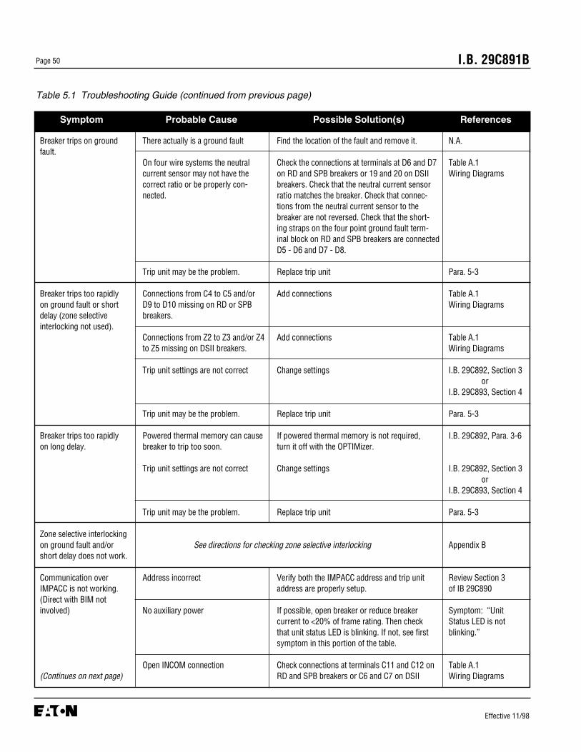
Breaker trips on ground There actually is a ground fault Find the location of the fault and remove it. N.A.fault.
On four wire systems the neutral Check the connections at terminals at D6 and D7 Table A.1current sensor may not have the on RD and SPB breakers or 19 and 20 on DSII Wiring Diagramscorrect ratio or be properly con- breakers. Check that the neutral current sensor nected. ratio matches the breaker. Check that connec-
tions from the neutral current sensor to the breaker are not reversed. Check that the short-ing straps on the four point ground fault term-inal block on RD and SPB breakers are connectedD5 - D6 and D7 - D8.
Trip unit may be the problem. Replace trip unit Para. 5-3
Breaker trips too rapidly Connections from C4 to C5 and/or Add connections Table A.1on ground fault or short D9 to D10 missing on RD or SPB Wiring Diagramsdelay (zone selective breakers.interlocking not used).
Connections from Z2 to Z3 and/or Z4 Add connections Table A.1to Z5 missing on DSII breakers. Wiring Diagrams
Trip unit settings are not correct Change settings I.B. 29C892, Section 3or
I.B. 29C893, Section 4
Trip unit may be the problem. Replace trip unit Para. 5-3
Breaker trips too rapidly Powered thermal memory can cause If powered thermal memory is not required, I.B. 29C892, Para. 3-6on long delay. breaker to trip too soon. turn it off with the OPTIMizer.
Trip unit settings are not correct Change settings I.B. 29C892, Section 3or
I.B. 29C893, Section 4
Trip unit may be the problem. Replace trip unit Para. 5-3
Zone selective interlockingon ground fault and/or See directions for checking zone selective interlocking Appendix Bshort delay does not work.
Communication over Address incorrect Verify both the IMPACC address and trip unit Review Section 3IMPACC is not working. address are properly setup. of IB 29C890(Direct with BIM notinvolved) No auxiliary power If possible, open breaker or reduce breaker Symptom: “Unit
current to <20% of frame rating. Then check Status LED is notthat unit status LED is blinking. If not, see first blinking.”symptom in this portion of the table.
Open INCOM connection Check connections at terminals C11 and C12 on Table A.1(Continues on next page) RD and SPB breakers or C6 and C7 on DSII Wiring Diagrams
I.B. 29C891BPage 50
Effective 11/98
Table 5.1 Troubleshooting Guide (continued from previous page)
Symptom Probable Cause Possible Solution(s) References
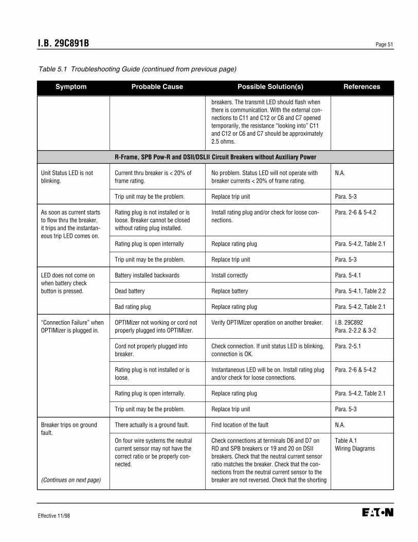
breakers. The transmit LED should flash when there is communication. With the external con-nections to C11 and C12 or C6 and C7 openedtemporarily, the resistance “looking into” C11and C12 or C6 and C7 should be approximately2.5 ohms.
R-Frame, SPB Pow-R and DSII/DSLII Circuit Breakers without Auxiliary Power
Unit Status LED is not Current thru breaker is < 20% of No problem. Status LED will not operate with N.A.blinking. frame rating. breaker currents < 20% of frame rating.
Trip unit may be the problem. Replace trip unit Para. 5-3
As soon as current starts Rating plug is not installed or is Install rating plug and/or check for loose con- Para. 2-6 & 5-4.2to flow thru the breaker, loose. Breaker cannot be closed nections.it trips and the instantan- without rating plug installed.eous trip LED comes on.
Rating plug is open internally Replace rating plug Para. 5-4.2, Table 2.1
Trip unit may be the problem. Replace trip unit Para. 5-3
LED does not come on Battery installed backwards Install correctly Para. 5-4.1when battery checkbutton is pressed. Dead battery Replace battery Para. 5-4.1, Table 2.2
Bad rating plug Replace rating plug Para. 5-4.2, Table 2.1
“Connection Failure” when OPTIMizer not working or cord not Verify OPTIMIzer operation on another breaker. I.B. 29C892OPTIMizer is plugged in. properly plugged into OPTIMizer. Para. 2-2.2 & 3-2
Cord not properly plugged into Check connection. If unit status LED is blinking, Para. 2-5.1 breaker. connection is OK.
Rating plug is not installed or is Instantaneous LED will be on. Install rating plug Para. 2-6 & 5-4.2loose. and/or check for loose connections.
Rating plug is open internally. Replace rating plug Para. 5-4.2, Table 2.1
Trip unit may be the problem. Replace trip unit Para. 5-3
Breaker trips on ground There actually is a ground fault. Find location of the fault N.A.fault.
On four wire systems the neutral Check connections at terminals D6 and D7 on Table A.1current sensor may not have the RD and SPB breakers or 19 and 20 on DSII Wiring Diagramscorrect ratio or be properly con- breakers. Check that the neutral current sensor nected. ratio matches the breaker. Check that the con-
nections from the neutral current sensor to the (Continues on next page) breaker are not reversed. Check that the shorting
I.B. 29C891B Page 51
Effective 11/98
Table 5.1 Troubleshooting Guide (continued from previous page)
Symptom Probable Cause Possible Solution(s) References

straps on the four point ground fault terminal block on the RD and SPB breakers are con- nected D5 - D6 and D7 - D8.
Trip unit may be the problem. Replace trip unit Para. 5-3
Breaker trips too rapidly Connection from C4 to C5 and/or Replace connections Table A.1on ground fault or short from D9 to D10 is missing on RD Wiring Diagramsdelay (zone selective or SPB breakers.interlocking not used).
Connection from Z2 to Z3 and/or Replace connections Table A.1Z4 to Z5 missing on DSII breakers. Wiring Diagrams
Trip unit settings are not correct. Change settings I.B. 29C892, Section 3or
I.B. 29C893, Section 4
Trip unit may be the problem. Replace trip unit Para. 5-3
Breaker trips too rapidly Unpowered thermal memory can If unpowered thermal memory is not required, I.B. 29C892, Para. 3-6on long delay. cause breaker to trip too soon. turn it off with the OPTIMizer.
Trip unit settings are not correct Change settings I.B. 29C892, Section 3or
I.B. 29C893, Section 4
Trip unit may be the problem. Replace trip unit Para. 5-3
Power values are grossly No voltage input to trip unit. Check PT disconnect plug is installed. Table A.1in error. (1050 Trip Units Wiring Diagramsonly)
Frequency incorrect Verify operating frequency with OPTIMizer I.B. 29C892, Para. 3-6
Trip unit may be the problem. Replace trip unit Para. 5-3
Zone selective interlockingon ground fault and/or See directions for checking zone selective interlocking Appendix Bshort delay does not work.
I.B. 29C891BPage 52
Effective 11/98
Table 5.1 Troubleshooting Guide (continued from previous page)
Symptom Probable Cause Possible Solution(s) References
Notes:(1) OPTIM Trip Units are not replaceable on Series C LD and ND circuit breakers. Because replacing the complete circuit breaker is difficult,
consult the factory before attempting replacement.
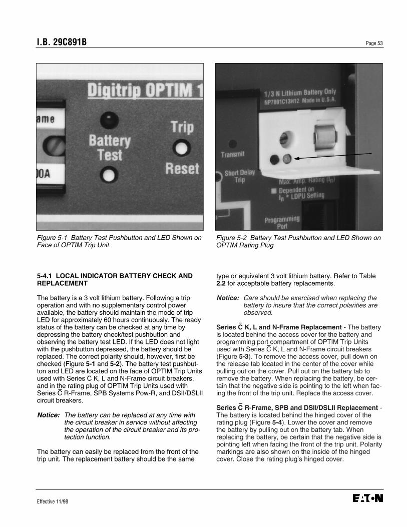
I.B. 29C891B Page 53
Effective 11/98
type or equivalent 3 volt lithium battery. Refer to Table2.2 for acceptable battery replacements.
Notice: Care should be exercised when replacing thebattery to insure that the correct polarities areobserved.
Series C K, L and N-Frame Replacement - The batteryis located behind the access cover for the battery andprogramming port compartment of OPTIM Trip Unitsused with Series C K, L and N-Frame circuit breakers(Figure 5-3). To remove the access cover, pull down onthe release tab located in the center of the cover whilepulling out on the cover. Pull out on the battery tab toremove the battery. When replacing the battery, be cer-tain that the negative side is pointing to the left when fac-ing the front of the trip unit. Replace the access cover.
Series C R-Frame, SPB and DSII/DSLII Replacement -The battery is located behind the hinged cover of therating plug (Figure 5-4). Lower the cover and removethe battery by pulling out on the battery tab. Whenreplacing the battery, be certain that the negative side ispointing left when facing the front of the trip unit. Polaritymarkings are also shown on the inside of the hingedcover. Close the rating plug’s hinged cover.
Figure 5-1 Battery Test Pushbutton and LED Shown onFace of OPTIM Trip Unit
Figure 5-2 Battery Test Pushbutton and LED Shown onOPTIM Rating Plug
5-4.1 LOCAL INDICATOR BATTERY CHECK ANDREPLACEMENT
The battery is a 3 volt lithium battery. Following a tripoperation and with no supplementary control poweravailable, the battery should maintain the mode of tripLED for approximately 60 hours continuously. The readystatus of the battery can be checked at any time bydepressing the battery check/test pushbutton andobserving the battery test LED. If the LED does not lightwith the pushbutton depressed, the battery should bereplaced. The correct polarity should, however, first bechecked (Figure 5-1 and 5-2). The battery test pushbut-ton and LED are located on the face of OPTIM Trip Unitsused with Series C K, L and N-Frame circuit breakers,and in the rating plug of OPTIM Trip Units used withSeries C R-Frame, SPB Systems Pow-R, and DSII/DSLIIcircuit breakers.
Notice: The battery can be replaced at any time withthe circuit breaker in service without affectingthe operation of the circuit breaker and its pro-tection function.
The battery can easily be replaced from the front of thetrip unit. The replacement battery should be the same
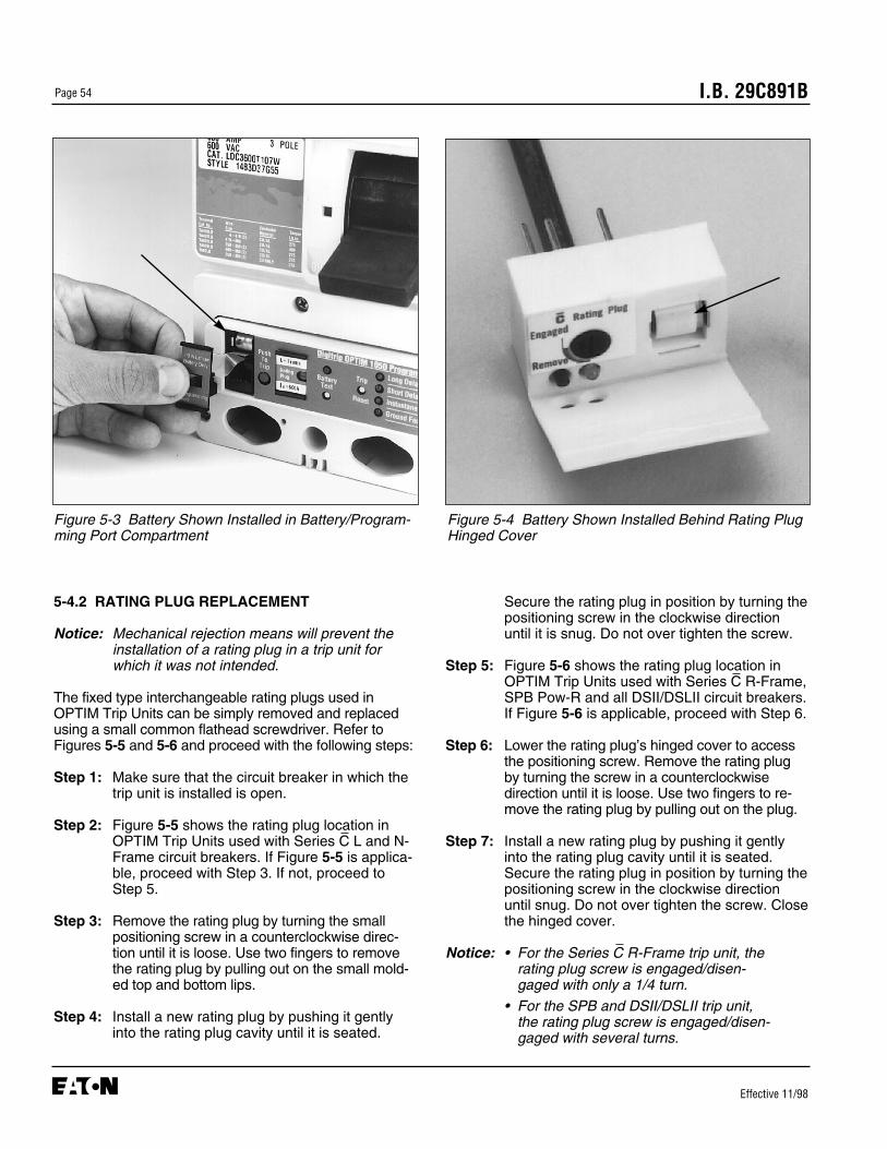
I.B. 29C891BPage 54
Effective 11/98
Figure 5-3 Battery Shown Installed in Battery/Program-ming Port Compartment
Figure 5-4 Battery Shown Installed Behind Rating PlugHinged Cover
5-4.2 RATING PLUG REPLACEMENT
Notice: Mechanical rejection means will prevent theinstallation of a rating plug in a trip unit forwhich it was not intended.
The fixed type interchangeable rating plugs used inOPTIM Trip Units can be simply removed and replacedusing a small common flathead screwdriver. Refer toFigures 5-5 and 5-6 and proceed with the following steps:
Step 1: Make sure that the circuit breaker in which thetrip unit is installed is open.
Step 2: Figure 5-5 shows the rating plug location inOPTIM Trip Units used with Series C L and N-Frame circuit breakers. If Figure 5-5 is applica-ble, proceed with Step 3. If not, proceed toStep 5.
Step 3: Remove the rating plug by turning the smallpositioning screw in a counterclockwise direc-tion until it is loose. Use two fingers to removethe rating plug by pulling out on the small mold-ed top and bottom lips.
Step 4: Install a new rating plug by pushing it gentlyinto the rating plug cavity until it is seated.
Secure the rating plug in position by turning thepositioning screw in the clockwise directionuntil it is snug. Do not over tighten the screw.
Step 5: Figure 5-6 shows the rating plug location inOPTIM Trip Units used with Series C R-Frame,SPB Pow-R and all DSII/DSLII circuit breakers.If Figure 5-6 is applicable, proceed with Step 6.
Step 6: Lower the rating plug’s hinged cover to accessthe positioning screw. Remove the rating plugby turning the screw in a counterclockwisedirection until it is loose. Use two fingers to re-move the rating plug by pulling out on the plug.
Step 7: Install a new rating plug by pushing it gentlyinto the rating plug cavity until it is seated.Secure the rating plug in position by turning thepositioning screw in the clockwise directionuntil snug. Do not over tighten the screw. Closethe hinged cover.
Notice: • For the Series C R-Frame trip unit, the rating plug screw is engaged/disen-gaged with only a 1/4 turn.
• For the SPB and DSII/DSLII trip unit, the rating plug screw is engaged/disen-gaged with several turns.

I.B. 29C891B Page 55
Effective 11/98
Figure 5-5 Rating Plug Shown Removed (L and N-Frame Type OPTIM Trip Units)
Figure 5-6 Rating Plug Shown Being Removed (R-Frame, SPB and DSII/DSLII Type OPTIM Trip Units)
5-5 RETURN PROCEDURE
The Troubleshooting Guide (Table 5.1) is intended forservice personnel to identify whether a problem beingobserved is external or internal to the device. If a prob-lem is determined to be internal, the device should bereturned to the factory for replacement. To have aDigitrip OPTIM Trip Unit returned, contact your localCutler-Hammer authorized distributor.
5-6 TECHNICAL ASSISTANCE
For information, technical assistance or referral to alocal authorized distributor, contact the CustomerSupport Center at 1-800-356-1243.

I.B. 29C891BPage 56
Effective 11/98
APPENDIX A - INSTRUCTIONAL REFERENCES
A list of instructional references is provided in Table A.1 to identify instructional documents that could be of assis-tance.
Table A.1 Instructional References (continued on next page)
DOCUMENT DESCRIPTION DOCUMENT NUMBER
Circuit Breakers
Series C K-Frame Frame Book IL 29-120K
Series C L-Frame Frame Book IL 29-120L
Series C N-Frame Frame Book IL 29-120N
Series C R-Frame Frame Book IL 29-120RSeries C R-Frame Supplement IL 29C713
SPB Systems Pow-R Breaker Supplement IL 29849
DSII/DSLII Breaker Supplement IL 8700C39
Digitrip OPTIM Trip Unit System
OPTIM Trip Unit System Overview IB 29C890
OPTIM Trip Units IB 29C891
OPTIMizer Hand Held Programmer IB 29C892
Breaker Interface Module IB 29C893
Digitrip RMS Trip Units
Digitrip RMS 810 IL 29-888
Digitrip RMS 910 IL 29-889
Digitrip OPTIM Wiring Diagrams
Series C K, L and N-Frame Wiring IL 29C894
Series C R-Frame Wiring IL 29C714
SPB Systems Pow-R Wiring IL 15545
DSII/DSLII Wiring IL 1A33600
Energy Monitoring Devices
IQ Energy Sentinel Series C F-Frame IL 17537Series C J-Frame IL 17538Series C K-Frame IL 17539
Universal IQ Energy Sentinel Internal IL 17540External IL 17541
Communication Devices
Communications Module (PONI) INCOM PONI IL 17547RS-232 PONI IL 17202Modem PONI IL 17203Buffered PONI IL 17361CONI IL 17436IMPACC Wiring Spec. IL 17513
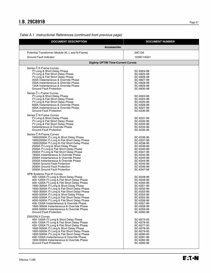
I.B. 29C891B Page 57
Effective 11/98
Table A.1 Instructional References (continued from previous page)
DOCUMENT DESCRIPTION DOCUMENT NUMBER
Accessories
Potential Transformer Module (K, L and N-Frame) 29C126
Ground Fault Indicator 1259C14G01
Digitrip OPTIM Time-Current Curves
Series C K-Frame CurvesI2t Long & Short Delay Phase SC-6924-98I2t Long & Flat Short Delay Phase SC-6925-98I4t Long & Flat Short Delay Phase SC-6926-98400A Instantaneous & Override Phase SC-6927-98250A Instantaneous & Override Phase SC-6928-98125A Instantaneous & Override Phase SC-6929-98Ground Fault Protection SC-6930-98
Series C L-Frame CurvesI2t Long & Short Delay Phase SC-6323-96I2t Long & Flat Short Delay Phase SC-6324-96I4t Long & Flat Short Delay Phase SC-6325-96600A Instantaneous & Override Phase SC-6326-96400A Instantaneous & Override Phase SC-6327-96Ground Fault Protection SC-6330-96
Series C N-Frame CurvesI2t Long & Short Delay Phase SC-6331-96I2t Long & Flat Short Delay Phase SC-6332-96I4t Long & Flat Short Delay Phase SC-6333-96Instantaneous & Override Phase SC-6334-96Ground Fault Protection SC-6335-96
Series C R-Frame Curves1600/2000A I2t Long & Short Delay Phase SC-6336-961600/2000A I2t Long & Flat Short Delay Phase SC-6337-961600/2000A I4t Long & Flat Short Delay Phase SC-6338-962500A I2t Long & Short Delay Phase SC-6339-962500A I2t Long & Flat Short Delay Phase SC-6340-962500A I4t Long & Flat Short Delay Phase SC-6341-961600A Instantaneous & Override Phase SC-6342-96 2000A Instantaneous & Override Phase SC-6343-96 2500A Instantaneous & Override Phase SC-6344-961600A Ground Fault Protection SC-6345-96 2000A Ground Fault Protection SC-6346-96 2500A Ground Fault Protection SC-6347-96
SPB Systems Pow-R Curves400-1200A I2t Long & Short Delay Phase SC-6348-96400-1200A I2t Long & Flat Short Delay Phase SC-6349-96400-1200A I4t Long & Flat Short Delay Phase SC-6350-961600-3000A I2t Long & Short Delay Phase SC-6351-961600-3000A I2t Long & Flat Short Delay Phase SC-6352-961600-3000A I4t Long & Flat Short Delay Phase SC-6353-964000-5000A I2t Long & Short Delay Phase SC-6354-964000-5000A I2t Long & Flat Short Delay Phase SC-6355-964000-5000A I4t Long & Flat Short Delay Phase SC-6356-96400-1200A Instantaneous & Override Phase SC-6357-961600-3000A Instantaneous & Override Phase SC-6358-964000-5000A Instantaneous & Override Phase SC-6359-96Ground Fault Protection SC-6360-96
DSII/DSLII Curves400-1200A I2t Long & Short Delay Phase SC-6275-95400-1200A I2t Long & Flat Short Delay Phase SC-6276-95400-1200A I4t Long & Flat Short Delay Phase SC-6277-951600-5000A I2t Long & Short Delay Phase SC-6278-951600-5000A I2t Long & Flat Short Delay Phase SC-6279-951600-5000A I4t Long & Flat Short Delay Phase SC-6280-95400-1200A Instantaneous & Override Phase SC-6281-961600-5000A Instantaneous & Override Phase SC-6282-96Ground Fault Protection SC-6283-96
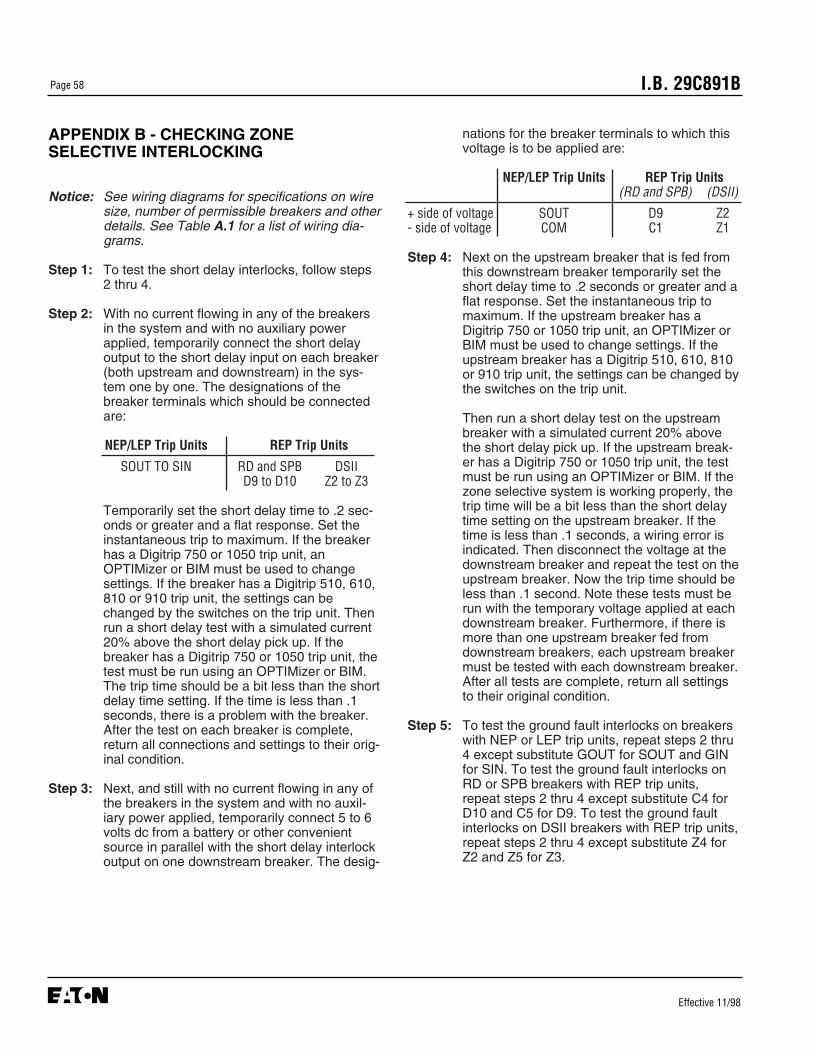
I.B. 29C891BPage 58
Effective 11/98
APPENDIX B - CHECKING ZONESELECTIVE INTERLOCKING
Notice: See wiring diagrams for specifications on wiresize, number of permissible breakers and otherdetails. See Table A.1 for a list of wiring dia-grams.
Step 1: To test the short delay interlocks, follow steps2 thru 4.
Step 2: With no current flowing in any of the breakersin the system and with no auxiliary powerapplied, temporarily connect the short delayoutput to the short delay input on each breaker(both upstream and downstream) in the sys-tem one by one. The designations of thebreaker terminals which should be connectedare:
NEP/LEP Trip Units REP Trip Units
SOUT TO SIN RD and SPB DSIID9 to D10 Z2 to Z3
Temporarily set the short delay time to .2 sec-onds or greater and a flat response. Set theinstantaneous trip to maximum. If the breakerhas a Digitrip 750 or 1050 trip unit, anOPTIMizer or BIM must be used to changesettings. If the breaker has a Digitrip 510, 610,810 or 910 trip unit, the settings can bechanged by the switches on the trip unit. Thenrun a short delay test with a simulated current20% above the short delay pick up. If thebreaker has a Digitrip 750 or 1050 trip unit, thetest must be run using an OPTIMizer or BIM.The trip time should be a bit less than the shortdelay time setting. If the time is less than .1seconds, there is a problem with the breaker.After the test on each breaker is complete,return all connections and settings to their orig-inal condition.
Step 3: Next, and still with no current flowing in any ofthe breakers in the system and with no auxil-iary power applied, temporarily connect 5 to 6volts dc from a battery or other convenientsource in parallel with the short delay interlockoutput on one downstream breaker. The desig-
nations for the breaker terminals to which thisvoltage is to be applied are:
NEP/LEP Trip Units REP Trip Units(RD and SPB) (DSII)
+ side of voltage SOUT D9 Z2- side of voltage COM C1 Z1
Step 4: Next on the upstream breaker that is fed fromthis downstream breaker temporarily set theshort delay time to .2 seconds or greater and aflat response. Set the instantaneous trip tomaximum. If the upstream breaker has aDigitrip 750 or 1050 trip unit, an OPTIMizer orBIM must be used to change settings. If theupstream breaker has a Digitrip 510, 610, 810or 910 trip unit, the settings can be changed bythe switches on the trip unit.
Then run a short delay test on the upstreambreaker with a simulated current 20% abovethe short delay pick up. If the upstream break-er has a Digitrip 750 or 1050 trip unit, the testmust be run using an OPTIMizer or BIM. If thezone selective system is working properly, thetrip time will be a bit less than the short delaytime setting on the upstream breaker. If thetime is less than .1 seconds, a wiring error isindicated. Then disconnect the voltage at thedownstream breaker and repeat the test on theupstream breaker. Now the trip time should beless than .1 second. Note these tests must berun with the temporary voltage applied at eachdownstream breaker. Furthermore, if there ismore than one upstream breaker fed fromdownstream breakers, each upstream breakermust be tested with each downstream breaker.After all tests are complete, return all settingsto their original condition.
Step 5: To test the ground fault interlocks on breakerswith NEP or LEP trip units, repeat steps 2 thru4 except substitute GOUT for SOUT and GINfor SIN. To test the ground fault interlocks onRD or SPB breakers with REP trip units,repeat steps 2 thru 4 except substitute C4 forD10 and C5 for D9. To test the ground faultinterlocks on DSII breakers with REP trip units,repeat steps 2 thru 4 except substitute Z4 forZ2 and Z5 for Z3.

I.B. 29C891B
Cutler-HammerPittsburgh, Pennsylvania U.S.A.
Effective 11/98Style 7801C96H03Printed in U.S.A.
This instruction booklet is published solely for informa-tion purposes and should not be considered all inclu-sive. If further information is required, you should con-sult Cutler-Hammer.
Sale of product shown in this literature is subject toterms and conditions outlined in appropriate Cutler-Hammer selling policies or other contractual agreementbetween the parties. This literature is not intended toand does not enlarge or add to any such contract. Thesole source governing the rights and remedies of anypurchaser of this equipment is the contract between thepurchaser and Cutler-Hammer.
NO WARRANTIES, EXPRESSED OR IMPLIED,INCLUDING WARRANTIES OF FITNESS FOR A PAR-TICULAR PURPOSE OR MERCHANTABILITY, ORWARRANTIES ARISING FROM COURSE OF DEAL-ING OR USAGE OF TRADE, ARE MADE REGARDINGTHE INFORMATION, RECOMMENDATIONS ANDDESCRIPTIONS CONTAINED HEREIN. In no eventwill Cutler-Hammer be responsible to the purchaser oruser in contract, in tort (including negligence), strict lia-bility or otherwise for any special, indirect, incidental orconsequential damage or loss whatsoever, including butnot limited to damage or loss of use of equipment, plantor power system, cost of capital, loss of power, addition-al expenses in the use of existing power facilities, orclaims against the purchaser or user by its customersresulting from the use of the information, recommenda-tions and description contained herein.