customer references - parametric design
TRANSCRIPT

›Consulting ›Training ›Software
Customer ReferencesDesign of a cylinder for winding thread guide Ing. Massimo Arcolin, Ermes Posenato

›Consulting ›Training ›Software
›01
Index
›02
›03
›04
›05
›06
Job description›The client›The product›The objective
Helical grooving of a cylinder: milling cutter movements
The problems of modelling a groove in Creo Parametric Essentials›Reproducing the mill cutter movements›Creating the surface - first method›Creating the surface - second method
Creating the finished cylinder
Notes on balancing procedures
Conclusions

›Consulting ›Training ›Software
›01
›Consulting ›Training ›Software
Leader Company in the production and commercialization of finishing machines for wool, cotton, linen, silk and synthetic threads: ›automatic spooler rockers ›double-torsion twisting machinery ›electronic couplers ›spoolers for continuous thickening and retraction ›open-end rotor thread spinners
Job description The client
›Consulting ›Training ›Software
›01Job description The product
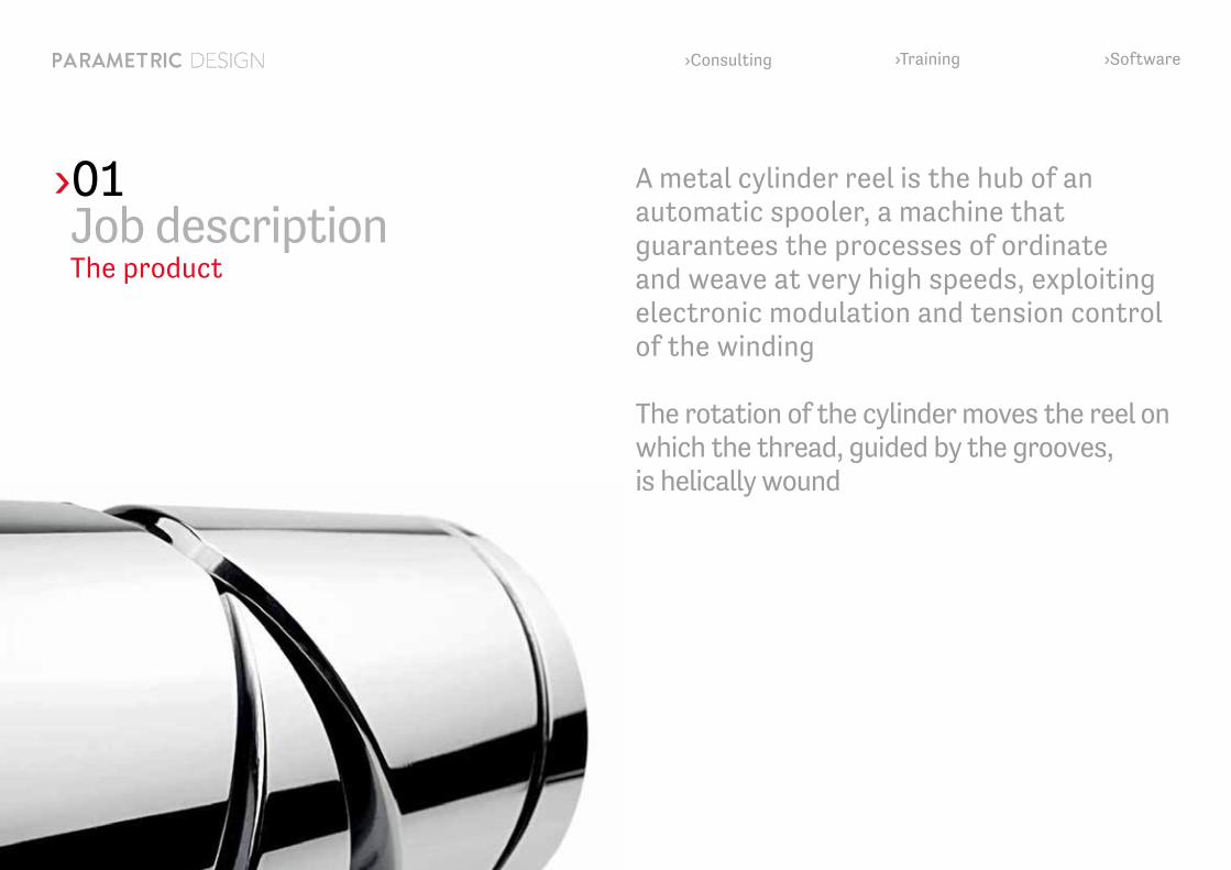
A metal cylinder reel is the hub of an automatic spooler, a machine that guarantees the processes of ordinate and weave at very high speeds, exploiting electronic modulation and tension control of the winding
The rotation of the cylinder moves the reel on which the thread, guided by the grooves, is helically wound

›Consulting ›Training ›Software
›01Job description The objective
›Consulting ›Training ›Software
Development of a method capable of furnishing solid-form modelling of the surface of the cylinder’s helical groove in Creo Parametric Essential, along with the CAM track of the instrument employed to create the actual geometry
Optimization of the design process for new geometries of the helical groove, with the possibility to execute suitable variations while carrying out real-time evaluation of the effects
›Creo Parametric Essentials›Creo AAX (Advanced Assembly Extension), Creo Simulation›Creo BMX (Behavioral Modeling Extension), Creo MDO (Mechanism Dynamics Option), › Creo REX (Reverse Engineering Extension)›Creo Complete Machining (CAM)›Scilab (Applicazione Matematica Open Source)
›

›Consulting ›Training ›Software
›02Helical grooving of the cylinder: movement of the mill cutter
The thread-guiding groove of the cylinder is designed to prevent the thread from crossing over on the reel and causing undesired changes of thickness in the spool
pass, depth and geometry of the section of the helicoid change along the cylinder axis
the section of the helix has a characteristic “drop-like” oval profile
› ›

›Consulting ›Training ›Software
The helicoidal groove is fisically realized through a mill cutter manufacture, driven by a numerical control machine with 5 axes
›
›02Helical grooving of the cylinder: movement of the mill cutter
The thread-guiding groove of the cylinder is designed to prevent the thread from crossing over on the reel and causing undesired changes of thickness in the spool
pass, depth and geometry of the section of the helicoid change along the cylinder axis
the section of the helix has a characteristic “drop-like” oval profile
› ›

›Consulting ›Training ›Software
›02Helical grooving of the cylinder: movement of the mill cutter
5 movements of the mill cutter:
›rotation around the cylinder (θ)›advancement along the axis (z)›depth of cut on the cylinder (r)›helix angle (α)›opening angle (β)
The helicoidal groove is fisically realized through a mill cutter manufacture, driven by a numerical control machine with 5 axes
›Consulting ›Training ›Software
›02Helical grooving of the cylinder: movement of the mill cutter
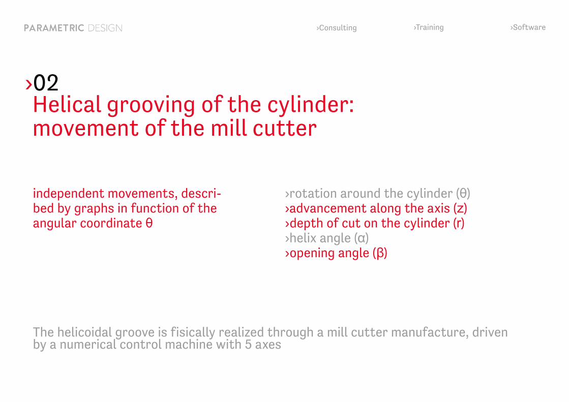
independent movements, descri-bed by graphs in function of the angular coordinate θ
›rotation around the cylinder (θ)›advancement along the axis (z)›depth of cut on the cylinder (r)›helix angle (α)›opening angle (β)
The helicoidal groove is fisically realized through a mill cutter manufacture, driven by a numerical control machine with 5 axes

›Consulting ›Training ›Software
movement determined by the advancement along the axes executed during an angular advancement:
›02Helical grooving of the cylinder: movement of the mill cutter
›rotation around the cylinder (θ)›advancement along the axis (z)›depth of cut on the cylinder (r)›helix angle (α)›opening angle (β)
The helicoidal groove is fisically realized through a mill cutter manufacture, driven by a numerical control machine with 5 axes
›Consulting ›Training ›Software
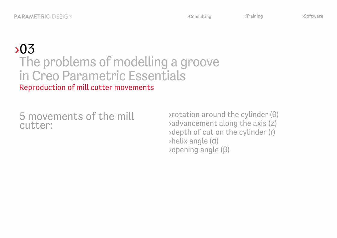
›03The problems of modelling a groove in Creo Parametric Essentials Reproduction of mill cutter movements
5 movements of the mill cutter:
›rotation around the cylinder (θ)›advancement along the axis (z)›depth of cut on the cylinder (r)›helix angle (α)›opening angle (β)

›Consulting ›Training ›Software
›03
The final geometry of the groove is unequivocally determined by the mill cutter profile and the 3 graphs that pilot the movement
The groove is the result of an ideal boolean subtraction from the cylinder of the space occupied by the bit during its movement
The problems of modelling a groove in Creo Parametric Essentials Reproduction of mill cutter movements
›5 movements of the mill cutter:
›rotation around the cylinder (θ)›advancement along the axis (z)›depth of cut on the cylinder (r)›helix angle (α)›opening angle (β)

›Consulting ›Training ›Software
›03
›importing the movement graphs intoCreo Parametric Essentials
›reading the graphs with the “evalgraph“ function
›sampling graphs to correctly position the coordinate-systems at fixed angular di-stances
›assembly of the mill cutter model on the coordinate-systems to reconstruct the movement of the mill cutter around the cylinder
The problems of modelling a groove in Creo Parametric Essentials Reproduction of mill cutter movements

›Consulting ›Training ›Software
›03
›exporting in STL format the space occupied by the mill cutter bits (a tessellated surface is obtained, not readable in CAM)
›smoothing technique that restores a smooth enveloped surface (using the REX Reverse Engineering Extension Module)
›employment of the obtained milling surfaces to reconstruct the external part of the cylinder
The problems of modelling a groove in Creo Parametric EssentialsCreating the surface - first method

›Consulting ›Training ›Software
›03
A program has been implemented that uses Scilab as calculation software to recon-struct, associatively, the groove surfaces
The program receives in input:›control graphs of the mill cutter path›geometries of the cylinder and the mill cutter bit›values of some correction-parameters necessary to control the results
Returns as output:›file .ibl which, read by Creo Parametric Essentials, permits the associative recon-struction of the helical groove geometry
The problems of modelling a groove in Creo Parametric EssentialsCreating the surface - second method

›Consulting ›Training ›Software
›Modelling the last features of the cylinder (ISDX module) ›vertex milling ›cords milling ›coursing lines ›radius
›Realizing the internal parts of the cylinder
›Checking sectors extraction with draft analysis
›Dynamic balancing (MDO and BMX modules)
›Passing the model in CAM environment to create a program of post- processing
›04Creation of the finished cylinder

›Consulting ›Training ›Software
›Finished cylinder ›Internal part
›04Creation of the finished cylinder

›Consulting ›Training ›Software
›05Notes on the balancing process
Dynamic balancing of the cylinder is obtained creating internal ribs and employing optimization analysis with the BMX module of Creo Parametric Essentials

›Consulting ›Training ›Software
›05Notes on the balancing process
Dynamic balancing of the cylinder is obtained creating internal ribs and employing optimization analysis with the BMX module of Creo Parametric Essentials
›Rotation of the cylinder at 600 revs/min
›Minimization of the radial moment M and the radial reaction force R
›Result: M = 5 Nmm ; R = 0.1N

›Consulting ›Training ›Software
›06Conclusions
Optimization of the procedure for the design of new geometries, thanks to the interactive modification of the movement charts with instant updating of the mill cutter track and the resulting final groove
Simultaneity of results, that is, obtaining the groove geometry and the CAM track that effectively creates it
Perfect repeatability and interchangeability of every model created
Advantages introduced by employment of the described procedure are multiple:
Employment of correction-parameters, that allow the regulation of the mill cutter movements and conseguently control the obtained result in the 3D model
Elimination of adjustment actions, previously necessary for the finishing features not obtainable on the machine

›Consulting ›Training ›Software
Thank you!
Swiss Operating Offices Parametric Design Suisse Sagl Corso San Gottardo 246830 Chiasso (Ch)
+41 91 945 31 40
Italian Operating Offices Parametric Design S.r.l. Piazza Corte Grande 24/25 20060 Gessate (MI)+39 02 95384199+39 02 95382708