custom integrated pneumatic rotary actuator for an …
TRANSCRIPT

CUSTOM, INTEGRATED, PNEUMATIC, ROTARY ACTUATOR
FOR AN ACTIVE ANKLE-FOOT ORTHOSIS
Richard Remmers†, Doug Cook
∗
, and Vito Gervasi∗
†Bucyrus, Intl., 1100 Milwaukee Street, Milwaukee, WI, 53172, USA
∗
Rapid-Prototyping Research, Milwaukee School of Engineering,1025 N. Broadway Street,
Milwaukee, WI, 53202, USA
ABSTRACT
End-use objects produced via additive manufacturing (AM) are on the rise and new
applications in the fluid power industry are emerging. Recently, a custom, pneumatic, rotary
actuator was been designed and additively manufactured for integration into an active ankle-foot
orthosis that is being developed in the National Science Foundation’s Center for Compact and
Efficient Fluid Power. All necessary plumbing, between the valves and vanes, is integrated into
the additively-manufactured housing of the actuator; and, the silicone translating seals were
vacuum-transfer molded using additively-manufactured molds and inserts. This non-
conventional actuator has more theoretical torque, and weighs less, than the off-the-shelf
component that it replaced. Further development will reduce seal leakage, and optimize designs
for additional mass reduction. Results-to-date are presented, in addition to several other
examples of the growing use of AM in the fluid-power industry.
1. INTRODUCTION
Purpose Applications of AM are expanding each year in a multitude of industries due to increased
AM awareness (through education), process and material improvements, and system cost
reductions. The fluid power (FP) industry has used AM for NPD for well over a decade, creating
prototype systems for form, fit, function and production. Now, end-use AM components and
systems are becoming a reality and this research project demonstrates mass reductions and
flexible reconfiguration options enabled by AM. The challenges faced on this project were to
produce a reduced-mass rotary actuator for an Active-Ankle-Foot-Orthosis (AAFO) within a
tight timeline with increased torque compared to the state-of-the-art off-the-shelf actuators
available. This project also served to fulfill a masters capstone design thesis for the completion
of MSE-ME. This paper has been prepared to share this example of AM technologies being
leveraged directly and indirectly to solve a real-world problem in the FP industry.
Scope
The approach to solving this problem was initially to create a model using National
Instruments LabView software to aid in establishment of a “working window” for size and
performance of the actuator. Next, an actuator was designed based on existing off-the-shelf
actuators with the added degrees of design freedom offered by AM fabrication. And finally, the
design was refined using several FEA packages to further reduce mass and increase housing
stiffness. A combination of AM-based fabrication and conventional machining was used for this
time-critical project. Other possible solutions were considered to generate the needed torque
including mechanically-linked cylinders, motors, and a yet-to-be-disclosed fluid power actuator.

Within the time constraints the “lower-risk” AM-based rotary actuator was chosen. The most
critical considerations in choosing the path for this actuator included time, mass, torque and size.
The timeframe was short at less tha 25 weeks and the mass needed to be less than one kilogram
for the entire AAFO. The torque target was 6-10 N-m and the size needed to be reasonable, with
a profile and compactness improvement over the current design.
Background The Center for Compact and Efficient Fluid Power (CCEFP) is a National Science
Foundation (NSF) Engineering Research Center (ERC) based at the University of Minnesota.
The CCEFP is a collaborative network of researchers, professors and industry partners working
to advance the field of fluid power technology. One of the Center’s design platforms, designated
Test Bed 6 (TB6), embodies research and design at the 10-to- 100-Watt-system range and is
currently the lowest-powered test bed of the Center. TB6 currently features the study of Active
Ankle Foot Orthosis (AAFO) technology. These are braces that help people who have lost
mobility in their ankle(s) by providing force to assist toe-up and toe-down motion. Under the
support of the Center for Compact and Effiecnet Fluid Power (CCEFP) the UIUC had
constructed an AAFO using an off-the-shelf rotary actuator and the unit, shown in Figure 1, was
functioning as intended with a few limiting factors including size, mass, and torque. The rotary
actuator provided more rotation than needed, 90 degrees. The specifications for the replacement
actuator were as follows:
• Mass less than 1 kg for entire AAFO
• Rotation of greater than 25 degrees
• Size and profile smaller than prototype I
• Torque target of 6-10 Nm
• Operating pressure of 0.35MPa
Efforts on prototype II began during mid-summer of 2009. Clinical testing of the AAFO
was scheduled to begin in late 2009 and the timely replacement of the “bulkier” configuration
was considered time-critical. To achieve the goal of upgrading the prototype I AAFO to meet the
specifications conventional actuator fabrication techniques were not able to provide the addition
of a “third” blade in the small actuator package needed to achieve the torque at the lower
Figure 1. Prototype 1 Active-Ankle-
Foot-Orthosis (AAFO), UIUC.

pressure and reduced mass. To address these design constraints AM was identified as the key
enabling technology to deliver the actuator in the desired time-frame to meet specifications.
The theory and knowledge-base informing the FP side of the project relied on basic fluid
mechanics theory. The AM side of this project drew form a general understanding of the
capabilities and limitations of AM obtained from experts and literature as well as suppliers and
material property data-sheets. A number of projects leveraging AM for fluid power components
and systems have been performed at the MSOE Rapid Prototyping Center including several by
former REU students. The first related project was titled, “Direct Manufacturing of Fluid Flow
Devices in a Single Build” by Wisner (shown in Figure 2a) and a more recent project titled,
“Additive Manufacturing of Fully Functional Fluid Power Components,” by Zientarski (Figure
2b). There are many examples of AM being used to create desirable FP actuator movement
through the use of additive technologies including the micro-fluidic actuator shown in Figure 2c.
This project leveraged the capability of AM to grow complex internal structure combined with
the tight-tolerance capability of traditional material removal methods, specifically CNC milling
and turning.
Actuator Design
The design goal was to reduce the number of individual components, and the size of the
actuator, in order to reduce both mass and potential leak sites. The pneumatic diagram shown in
Figure 3 illustrates the sub-system functions to meet the specifications for the AAFO. The grey
shaded region includes those components integrated into the custom fluid-power system. The
power source is regulated externally to provide two separate pressure levels, allowing for the
generation of different torque outputs in either direction of rotation. Actuation is controlled by
two, solenoid, directional-control valves; and, the pressure in the actuator is released to
atmosphere through an adjustable flow-control valve and silencer. This setup provides more
control over rate-of-motion and exhaust noise.
Figure 2. Fluid Power Actuators Grown Directly using Additive Manufacturing (2a-
Wisner-2004, 2b-Zientarski-2009, 2c-Kang-2004).
2a 2b 2c

Figure
50 psi
30 psi
Figure 3: Pnuematic Diagram of Prototype System
One of the most outstanding features of this actuator is the use of blind, internal passages
to connect different control volumes. Actuators with two rotor blades
typical methods of connecting the chambers use conventional machining operations, e.g. a hole
drilled tangentially through the center shaft. Adding a third blade
blade form, necessitating an alternate
to be connected and supplied the same pressure
One design path would have been to attempt drilling three holes in the center shaft that
met in the center at one location and three more holes
method would have the top two chambers pictured in
other two chambers would be connected through the top chamber.
The preferred design utilizes the unique capabilities of AM to create channels that could
only be generated via an additive process. There is no line
circumferential channels that connect all of the chambers to their respective valves, and allow for
more uniform pressurization. Figure
volumes (blue channels are hidden behind red).
Figure 4: Actuator Housing Channels
3: Pnuematic Diagram of Prototype System
utstanding features of this actuator is the use of blind, internal passages
l volumes. Actuators with two rotor blades are quite common and
typical methods of connecting the chambers use conventional machining operations, e.g. a hole
center shaft. Adding a third blade complicated the typical two
n alternate approach. As shown in Figure 4, the red sections needed
lied the same pressure -- likewise for the blue sections.
One design path would have been to attempt drilling three holes in the center shaft that
met in the center at one location and three more holes at a parallel location along the shaft. This
d would have the top two chambers pictured in Figure 4 supplied by the manifold and the
other two chambers would be connected through the top chamber.
The preferred design utilizes the unique capabilities of AM to create channels that could
ted via an additive process. There is no line-of-sight for a tool to create these
circumferential channels that connect all of the chambers to their respective valves, and allow for
Figure 4 shows these channels colored to match the control
volumes (blue channels are hidden behind red).
utstanding features of this actuator is the use of blind, internal passages
are quite common and
typical methods of connecting the chambers use conventional machining operations, e.g. a hole
complicated the typical two-
, the red sections needed
likewise for the blue sections.
One design path would have been to attempt drilling three holes in the center shaft that
at a parallel location along the shaft. This
4 supplied by the manifold and the
The preferred design utilizes the unique capabilities of AM to create channels that could
sight for a tool to create these
circumferential channels that connect all of the chambers to their respective valves, and allow for
tch the control
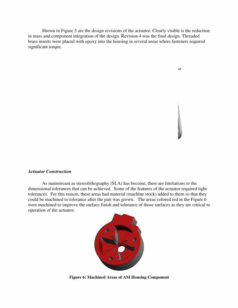
Figure 5. Custom Actuator Design Revisions and Final Design (Revision 4).
Shown in Figure 5 are the design revisions of the actuator. Clearly visible is the reduction
in mass and component integration of the design. Revision 4 was the final design
brass inserts were placed with epoxy into the housing in several areas where fasteners required
significant torque.
Actuator Construction
As mainstream as stereolithography
dimensional tolerances that can be achieved. Some of the features of the actuator required tight
tolerances. For this reason, these areas had material (machine stock) added to them so that they
could be machined to tolerance after the part was
were machined to improve the surface finish and tolerance of those surfaces as they are critical to
operation of the actuator.
Figure 6: Machined Areas of AM Housing Component
Custom Actuator Design Revisions and Final Design (Revision 4).
5 are the design revisions of the actuator. Clearly visible is the reduction
and component integration of the design. Revision 4 was the final design
brass inserts were placed with epoxy into the housing in several areas where fasteners required
as stereolithography (SLA) has become, there are limitations to the
l tolerances that can be achieved. Some of the features of the actuator required tight
tolerances. For this reason, these areas had material (machine stock) added to them so that they
could be machined to tolerance after the part was grown. The areas colored red in the
were machined to improve the surface finish and tolerance of those surfaces as they are critical to
6: Machined Areas of AM Housing Component
5 are the design revisions of the actuator. Clearly visible is the reduction
and component integration of the design. Revision 4 was the final design. Threaded
brass inserts were placed with epoxy into the housing in several areas where fasteners required
has become, there are limitations to the
l tolerances that can be achieved. Some of the features of the actuator required tight
tolerances. For this reason, these areas had material (machine stock) added to them so that they
olored red in the Figure 6
were machined to improve the surface finish and tolerance of those surfaces as they are critical to

The seal located between the actuator housing and the ba
laser cutting system. The laser cut out a
70A durometer rubber.
Figure 7: Seal
This method of making seals was found to work well
by the laser are not critical for sealing.
a rubber gasket sheet provided an
The most challenging part of this design and construction was the fabrication of the
dynamic seals that reside in groove
housing resulting in a moving seal on the rotor shaft. Their function is to form a seal betw
the rotor blade (or shaft) and the housing surfaces to maintain a pressure differential as needed to
generate torque output while at the same time providing a sliding seal within the housing. The
challenge, then, is that the seals must: be rigid enoug
operating pressure; slide with minimal friction across the sealing surfaces; and, conform to any
imperfections.
Figure
between the actuator housing and the back plate was created using a
cut out a the seal, shown in Figure 7, from a sheet of Buna
7: Seal Between Back Plate to Actuator Housing
This method of making seals was found to work well for static seals where the faces cut
by the laser are not critical for sealing. Using only the as-manufactured top and bottom faces of
n adequate seal between the back plate and the actuator housing.
nging part of this design and construction was the fabrication of the
dynamic seals that reside in grooves on the three rotor blades (Figure 8) and in the actuator
housing resulting in a moving seal on the rotor shaft. Their function is to form a seal betw
the rotor blade (or shaft) and the housing surfaces to maintain a pressure differential as needed to
generate torque output while at the same time providing a sliding seal within the housing. The
challenge, then, is that the seals must: be rigid enough to resist deformation at maximum
operating pressure; slide with minimal friction across the sealing surfaces; and, conform to any
Figure 8: Three-bladed Rotor and Shaft.
s created using a
7, from a sheet of Buna-N
for static seals where the faces cut
top and bottom faces of
adequate seal between the back plate and the actuator housing.
nging part of this design and construction was the fabrication of the
8) and in the actuator
housing resulting in a moving seal on the rotor shaft. Their function is to form a seal between
the rotor blade (or shaft) and the housing surfaces to maintain a pressure differential as needed to
generate torque output while at the same time providing a sliding seal within the housing. The
h to resist deformation at maximum
operating pressure; slide with minimal friction across the sealing surfaces; and, conform to any

The initial attempts to create the dynamic seals were made using the same laser-cutting
technique used for the housing-to-back-plate seal. It was desired to use a low-durometer rubber
for these seals so they would be more likely to conform to the surfaces. The laser cutter could
cut shore 70A rubber; but it would simply melt rubber with shore hardness less than 50A. No
usable seals could be made out of the lower durometer rubber using the available laser cutter
system. The shore 70A rubber was used for many attempts to make dynamic seals. Due to the
width of the laser beam, there is a degree of inaccuracy in converting the CAD file to a seal; this
is also affected by the precision of the linear stages and focus of the laser beam. The laser cut
creates an irregular finish on the cut faces that resulted in leakage.
Several sets of seals were made with varying widths. The goal was to find the proper
thickness of seal that would create the optimal tradeoff between sealing and friction. On one
occasion, when testing these seals the actuator did move, albeit with very little torque. This was
an encouraging moment; however, on the following day, the lubricant used in the actuator had
been absorbed by the rubber causing it to swell. The actuator essentially locked up.
A superior method of forming these insert seals was later used, again leveraging additive
manufacturing. A single-cavity silicone-transfer-mold was constructed from tool steel, and
included a receptacle for an AM mold insert that contained the geometry of the seals, as well as
the mold gating. Figure 9 shows the mold design, with the top portion rendered transparent.
Tool steel was chosen because it was readily available in plates, and was already ground and
lapped to an appropriate surface finish for the mold. Steel is also durable enough to withstand
the frequent tightening and loosening of the bolts that hold the mold halves together. The AM
mold insert (shown to the lower right in Figure 9) was thin, at 1.6 mm (1/16 in), to allow rapid
build-times, therefore, multiple iterations could be made if necessary to adjust size and design to
achieve a functional seal. A very low (shore10A) durometer silicone was cast to produce a set of
low durometer seals.
Figure 9: Steel Transfer Mold and AM Mold Insert
Over-Molded Seals
Additionally, considerations were made for over-molding the blades of the actuator rotor
with an elastomer. The lower shear loading at the blade tip, relative to the root, afforded a radial,

tapered reduction in blade cross-sectional area, thereby increasing the area available for an
elastomeric seal. Once again employing additive manufacturing, a silicone-transfer mold was
fabricated using the Watershed™ resin, as was a prototype of the proposed rotor geometry
(Figure 10). The transparency of this material, achieved with moderate sanding and buffing,
allowed for inspection of the silicone flow; so that, trapped air, and any other potential defects,
could be addressed before the material cured.
Figure 10: Vacuum-transfer Mold for Overmolding the Blades of the Actuator Rotor with an Elastomeric-seal Geometry.
Results and Discussion Through mass- and size-reducing design, the custom actuator is significantly smaller,
lighter and more compact than the original prototype. It is difficult to give a direct comparison
of the first prototype actuator to the new prototype actuator because the new actuator
incorporates many components in its assembly. However, Table 1 shows the contrast in mass,
along with the performance specifications of the prototype I actuator alone to the custom
actuator.
Table 1: Revision Comparison
Prototype I Custom Actuator
Components SMC Rotary Vane
Actuator CRB2BW40-
90D-DIM00653 (alone,
no valves/lines/etc.)
Rotary Vane Actuator, two
directional control valves, two flow
control valves, orthotic strut brace,
electronics board
Mass 390 g 372 g
Torque 5 N-m at 0.35 MPa 4 N-m at 0.35 MPa
Rotation
Angle
90° 55°
Figure 11a and 11b illustrate the SMC actuator and custom actuator (with the additional
components listed in Table 1 installed, less the electronics board).

(a) (b)
Figure 11: Revision One and Revision Two Actuators
Graph 1 illustrates the performance of the SMC actuator compared to the new actuator.
Notable here is the drop-off in torque as pressure increases to 0.35 MPa. the drop-off in torque is
attributed to friction and internal leakage of the dynamic seals. Improvements in sealing were
achieved during this stage of the project but an effort to optimize the geometry and durometer of
the dynamic seals to achieve the theoretical 7 N-m was not carried out. Despite these challenges,
the actuator has successfully demonstrated the use of AM to create a functional fluid power
component. It has been tested up to 3,000 cycles. After more refinement of the seals, this
actuator will be tested more extensively and the dynamics of the system will be identified to be
used in developing the control system for the AAFO. Shown in Figure 12 is the orthosis with the
actuator integrated into the unit.
Graph 1: Revision One and Revision Two Actuators
Actuator Revision Comparisons
0
1
2
3
4
5
6
7
0 0.05 0.1 0.15 0.2 0.25 0.3 0.35 0.4 0.45
Pressure [MPa]
Torq
ue [N-m
]
MSOE Rotary
SMC CRB2BW40
Actuator Revision Comparisons

Figure 13 shows the result of the first
(PDMS). While the fit of the assembly was good, changes in the performance requirements of
this actuator have prevented us from testing the functionality of the over
generation must provide more torque, and, therefore, must handle higher pressures to remain
compact.
Figure 13: Over-molded silicone seals on the (center). The tapered blade within
The torque requirements of this compact actuator necessitate the use of high
materials, e.g. steel, for the rotor’s shaft and blade roots. Future prototypes may integrate the two
materials. Ultimately, as additive technologies progress, such multi
elastomer) rotors might be fabricated in one process.
Conclusions
It has been demonstrated that additive manufacturing is useful for creating functional
fluid power components and tooling for creating seals for said components. AM has made a
tremendous impact in changing the methods use
Figure
integrated Actuator.
shows the result of the first over-molded seal trial, using Polydimethyl
While the fit of the assembly was good, changes in the performance requirements of
this actuator have prevented us from testing the functionality of the over-molded seals. The next
generation must provide more torque, and, therefore, must handle higher pressures to remain
one seals on the actuator rotor (left) and the fit into the housing within can be seen in contrast to the silicone, being flexed (right)
he torque requirements of this compact actuator necessitate the use of high
rotor’s shaft and blade roots. Future prototypes may integrate the two
ltimately, as additive technologies progress, such multi-material (metal and
rotors might be fabricated in one process.
It has been demonstrated that additive manufacturing is useful for creating functional
fluid power components and tooling for creating seals for said components. AM has made a
tremendous impact in changing the methods used to produce many custom personal products
Figure 12. Assembled AAFO with
integrated Actuator.
Polydimethyl-siloxane
While the fit of the assembly was good, changes in the performance requirements of
molded seals. The next
generation must provide more torque, and, therefore, must handle higher pressures to remain
actuator rotor (left) and the fit into the housing
, being flexed (right).
he torque requirements of this compact actuator necessitate the use of high-strength
rotor’s shaft and blade roots. Future prototypes may integrate the two
aterial (metal and
It has been demonstrated that additive manufacturing is useful for creating functional
fluid power components and tooling for creating seals for said components. AM has made a
d to produce many custom personal products.

For this application, plumbing and multiple components were integrated into a single housing.
AM potential has yet to be fully utilized in many engineered components. Through the use of
AM, the disparity between an ideal design and a feasibly manufactured component can be
reduced.
Future Work
Consideration of higher pressure actuators has begun and future actuator operating
pressures may increase to greater than 500psi and air may be replaced with hydraulic fluid.
Acknowledgements
The authors would like to thank the National Science Foundation (NSF) and the Center
for Compact and Efficient Fluid Power (CCEFP) for funding and support of this Research. This
material is based upon work supported by the National Science Foundation under Grant No.
EEC-0540834. Alex Shorter is recognized for his work on the first AAFO prototype that created
the opportunity for this project. Also, Keith Nordgulen at SMC Milwaukee is acknowledged for
his help. Any opinions, findings, and conclusions or recommendations expressed in this
material are those of the author(s) and do not necessarily reflect the views of the National
Science Foundation
References
3D Systems “Viper™ SLA® system” [Internet, WWW, PDF] Available:
Available in .PDF format; Address:
http://www.3dsystems.com/products/sla/viper/ViperSLA_%20US_Engl_rev0806.pdf [Accessed: 25 May
2010].
CCEFP (2009) “Transforming Fluid Power through Research | Center for Compact and Efficient Fluid
Power.” [Internet, WWW]. Available: University of Minnesota Website; Address:
http://www.ccefp.org/research. [Accessed: 23 July 2009].
DMS Somos. (2007). “Watershed XC 11122” [Internet, WWW, PDF] Available:
Available in .PDF format; Address:
http://www.interpro-rtc.com/Somos11122_XC.pdf. [Accessed: 25 May 2010].
Hague, R.; Mansour, S.; Saleh, N.. (2004). "Material and design considerations for rapid
manufacturing" International Journal of Production Research 42.22 24
http://www.informaworld.com/10.1080/00207840410001733940 [Accessed: 25 May 2010].
Herr, Hugh M. and Roy D. Kornbluh. (4 August 2004). “New horizons for orthotic and
prosthetic technology: artificial muscle for ambulation,” Proc. SPIE 5385, 1.
Hsiao-Wecksler, Elizabeth T., PhD., Géza F Kogler., PhD, C.O., K. Alex. Shorter. (6 June 2009).
Meeting with design teams, Champaign, IL.
Kang, Hyun-Wook, In Hwan Lee, Dong-Woo Cho, “Development of an Assembly-free
Process Based on Virtual Environment for Fabricating 3D Microfluidic Systems Using
Microstereolithography Technology,” Journal of Manufacturing Science and Engineering, November
2004. Volume 126, Issue 4, pg766-772.

SMC (2010) “Rotary Actuator Vane Style Series CRB2” [Internet, WWW] Available: Available from
SMC website; Address: http://content.smcetech.com/pdf/crb2.pdf [Accessed: 25 May 2010].
Structure Probe, Inc. (2010) “Braycote® 1632 Vacuum Grease Expected Properties” [Internet, WWW]
Available: Available from SPI website; Address: http://www.2spi.com/catalog/vac/braycote-1632-
properties.html. [Accessed: 25 May 2010].
Wisner, Derek M. (21 April 2005). Direct Manufacturing of Fluid Flow Devices in a Single
Build,” Proc. NCUR 2005.
Zientarski, Sara (15 April 2010). “Additive Manufacturing of Fully Functional Fluid Power
Components,” Proc. NCUR 2010.