curve based • analytical •external -...
TRANSCRIPT
81Machinery Motor Tutorial
Machinery Motor TutorialThe Adams/Machinery Motor module provides for the modeling of motor systems within the Adams/View environment.
Three modeling methods are available:
• Curve Based
• Analytical
• External
Getting Started Using Adams/MachineryCurve Based
82
Curve BasedThe Adams/Machinery Motor module provides for the modeling of motor systems within the Adams/View environment. It supports multiple modeling methodology options. This example shows how to create motor using the curve-based method from the minimal set of input parameters.
This chapter includes the following sections:
• What You Will Create
• Curve Based Method Motor Model
• Simulation
• Adams/PostProcessor Results
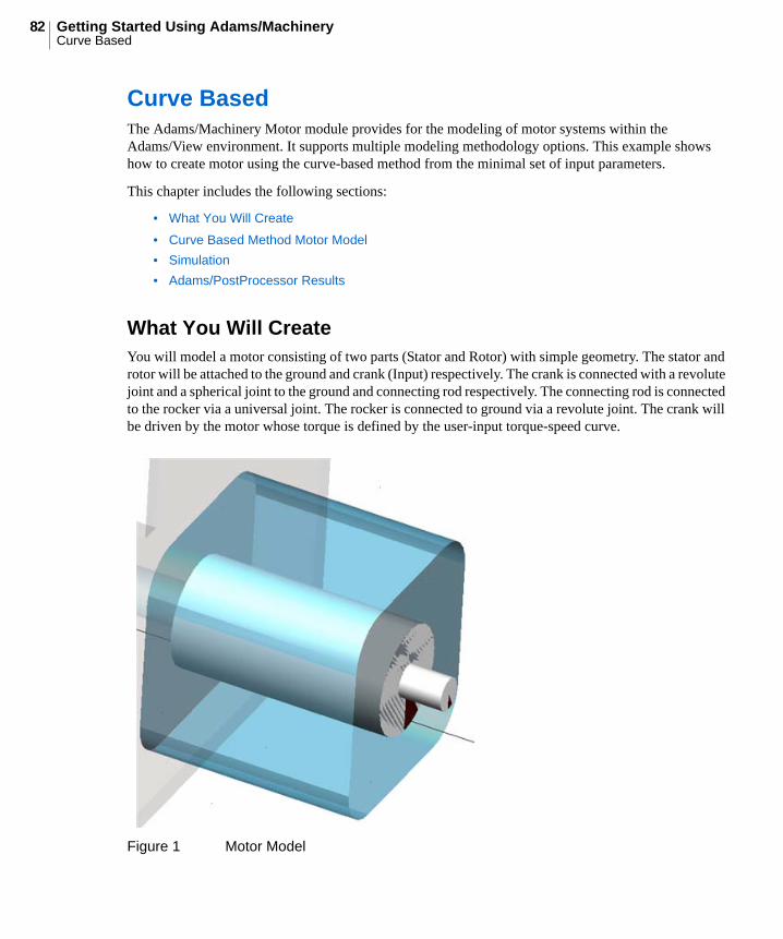
What You Will CreateYou will model a motor consisting of two parts (Stator and Rotor) with simple geometry. The stator and rotor will be attached to the ground and crank (Input) respectively. The crank is connected with a revolute joint and a spherical joint to the ground and connecting rod respectively. The connecting rod is connected to the rocker via a universal joint. The rocker is connected to ground via a revolute joint. The crank will be driven by the motor whose torque is defined by the user-input torque-speed curve.
Figure 1 Motor Model
83Machinery Motor TutorialCurve Based
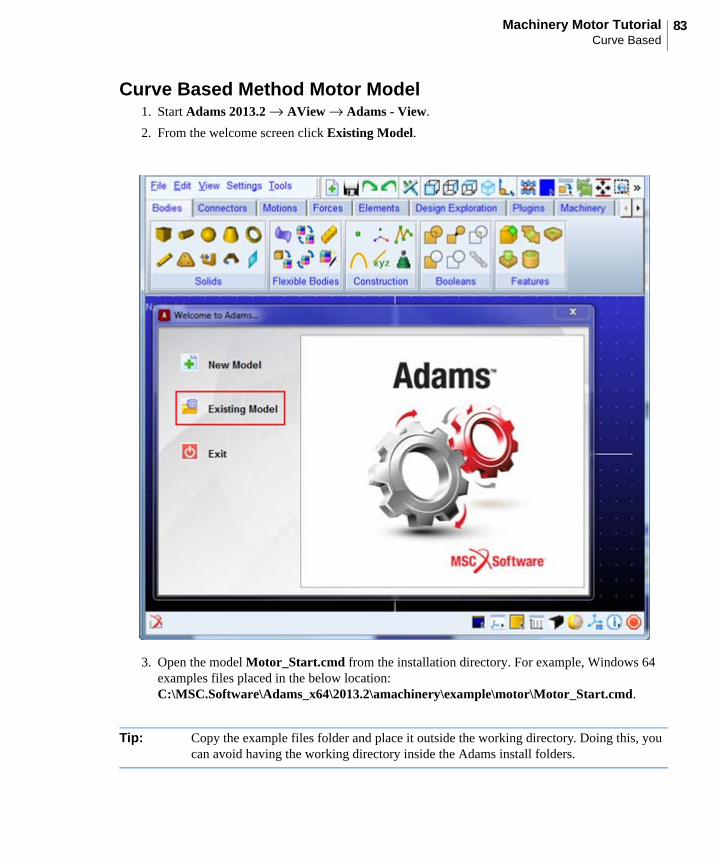
Curve Based Method Motor Model1. Start Adams 2013.2 → AView → Adams - View.
2. From the welcome screen click Existing Model.
3. Open the model Motor_Start.cmd from the installation directory. For example, Windows 64 examples files placed in the below location:C:\MSC.Software\Adams_x64\2013.2\amachinery\example\motor\Motor_Start.cmd.
Tip: Copy the example files folder and place it outside the working directory. Doing this, you can avoid having the working directory inside the Adams install folders.

Getting Started Using Adams/MachineryCurve Based
84

85Machinery Motor TutorialCurve Based
4. The imported model will look like the one shown below.
a. It has:
• Crank geometry connected with revolute and spherical joint with ground and connecting rod
• Connecting rod is connected to rocker with universal joint
• Rocker is connected to ground with revolute joint
5. Click the Machinery tab on the Adams/View ribbon.
Getting Started Using Adams/MachineryCurve Based
86
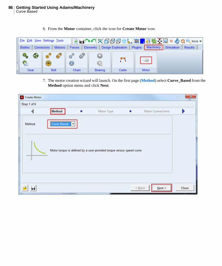
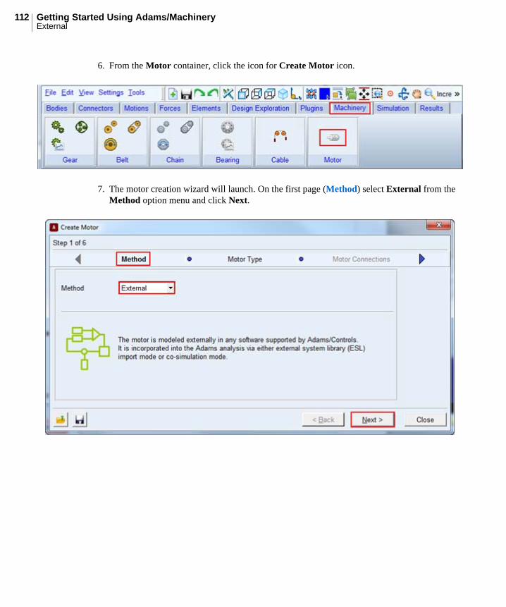
6. From the Motor container, click the icon for Create Motor icon.
7. The motor creation wizard will launch. On the first page (Method) select Curve_Based from the Method option menu and click Next.
87Machinery Motor TutorialCurve Based
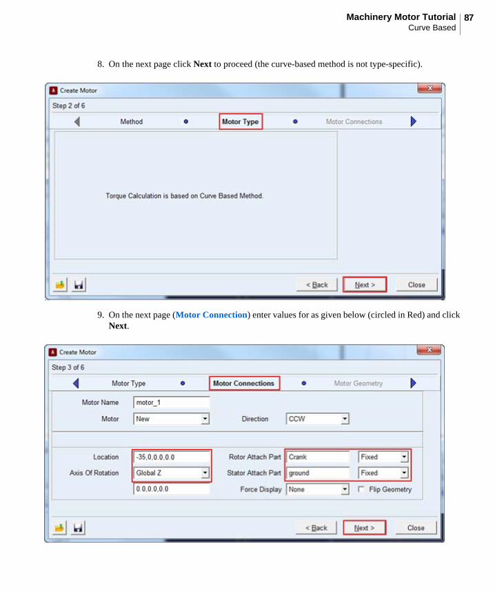
8. On the next page click Next to proceed (the curve-based method is not type-specific).
9. On the next page (Motor Connection) enter values for as given below (circled in Red) and click Next.
Getting Started Using Adams/MachineryCurve Based
88
a. Enter the values for the following fields and accept the defaults for others as shown below
• Axis of Rotation as “Global Z”.
• Enter the values “-35.0,0.0,0.0” in mm for location.
• Rotor attach part as “Crank” from right-mouse-button option Guesses.
• Stator attach part as “ground” from right-mouse-button option Guesses.
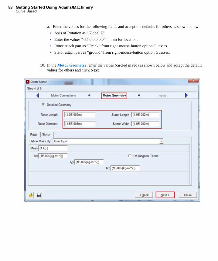
10. In the Motor Geometry, enter the values (circled in red) as shown below and accept the default values for others and click Next.
89Machinery Motor TutorialCurve Based
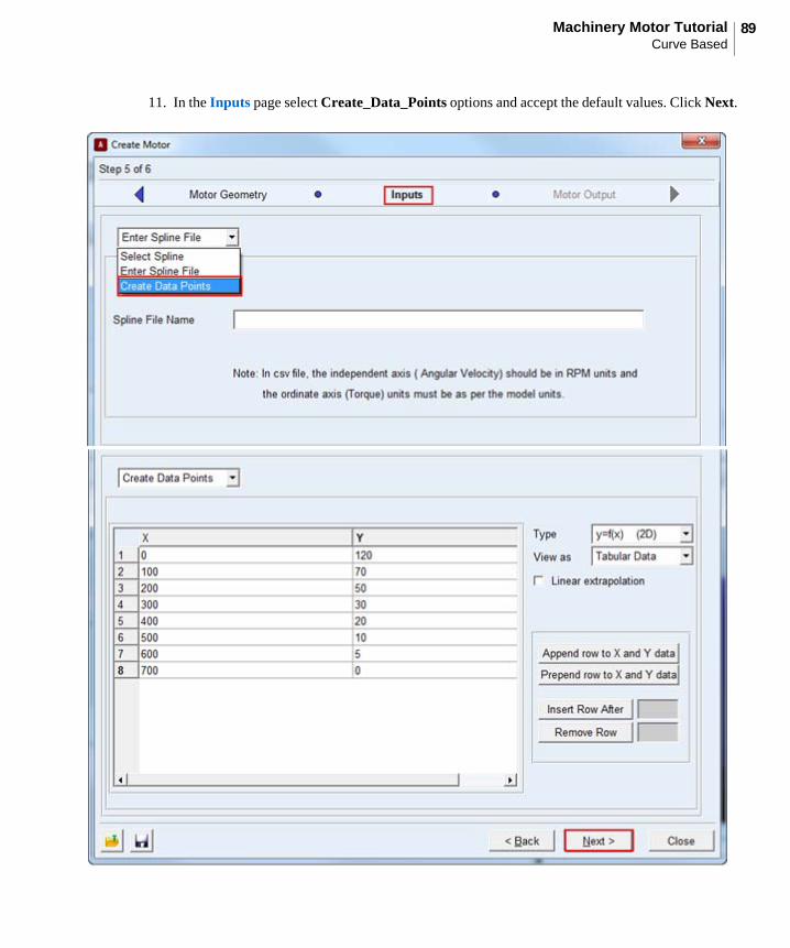
11. In the Inputs page select Create_Data_Points options and accept the default values. Click Next.
Getting Started Using Adams/MachineryCurve Based
90
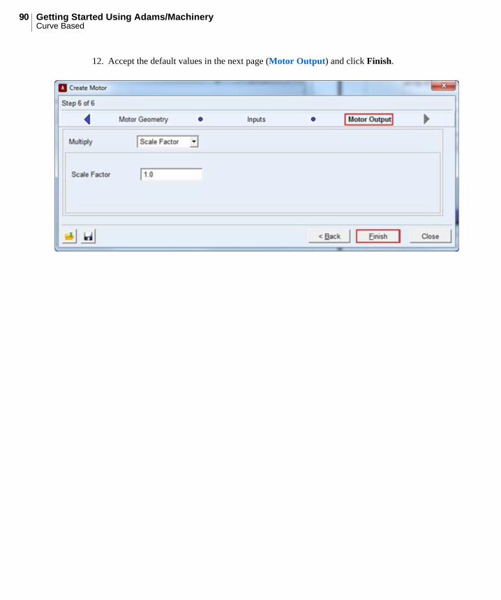
12. Accept the default values in the next page (Motor Output) and click Finish.
91Machinery Motor TutorialCurve Based
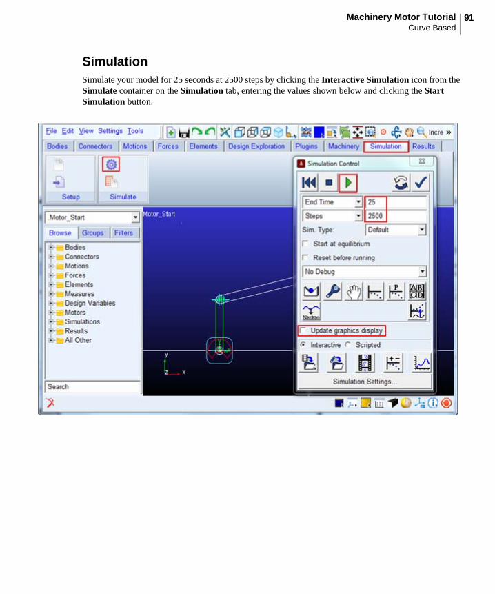
SimulationSimulate your model for 25 seconds at 2500 steps by clicking the Interactive Simulation icon from the Simulate container on the Simulation tab, entering the values shown below and clicking the Start Simulation button.
Getting Started Using Adams/MachineryCurve Based
92
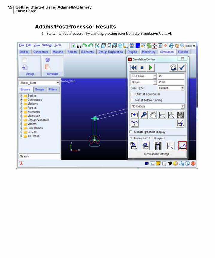
Adams/PostProcessor Results1. Switch to PostProcessor by clicking plotting icon from the Simulation Control.
93Machinery Motor TutorialCurve Based
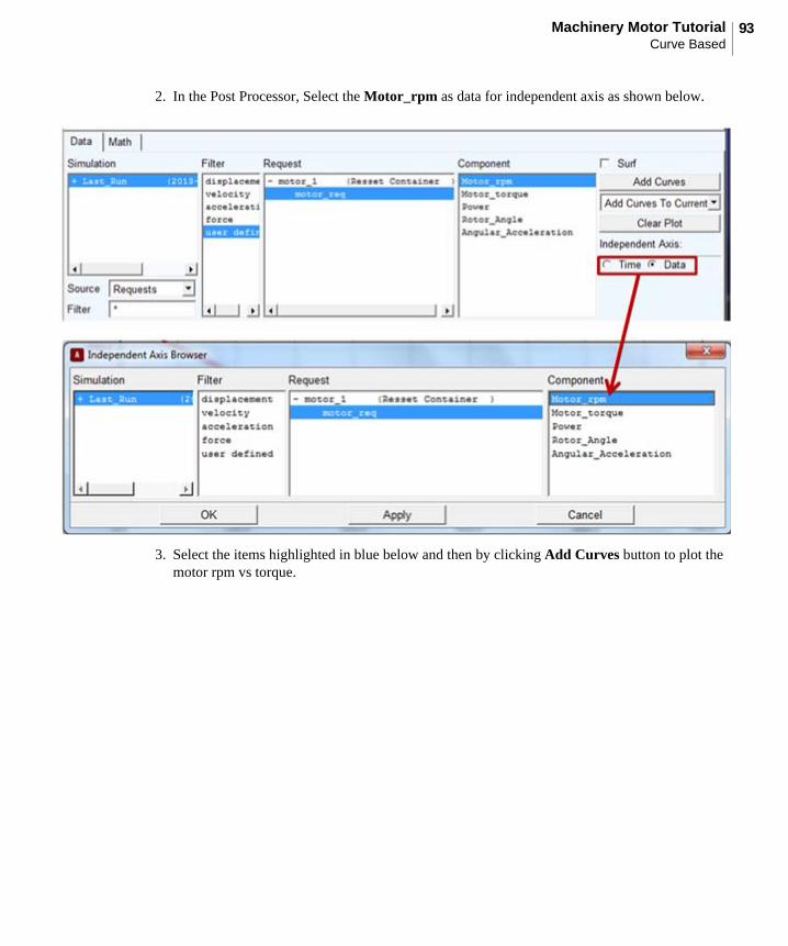
2. In the Post Processor, Select the Motor_rpm as data for independent axis as shown below.
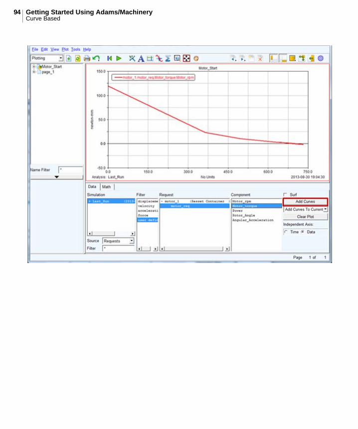
3. Select the items highlighted in blue below and then by clicking Add Curves button to plot the motor rpm vs torque.
Getting Started Using Adams/MachineryCurve Based
94
95Machinery Motor TutorialAnalytical
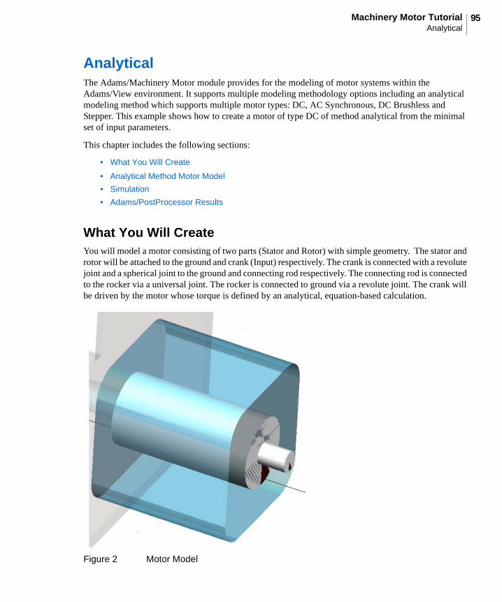
AnalyticalThe Adams/Machinery Motor module provides for the modeling of motor systems within the Adams/View environment. It supports multiple modeling methodology options including an analytical modeling method which supports multiple motor types: DC, AC Synchronous, DC Brushless and Stepper. This example shows how to create a motor of type DC of method analytical from the minimal set of input parameters.
This chapter includes the following sections:
• What You Will Create
• Analytical Method Motor Model
• Simulation
• Adams/PostProcessor Results
What You Will CreateYou will model a motor consisting of two parts (Stator and Rotor) with simple geometry. The stator and rotor will be attached to the ground and crank (Input) respectively. The crank is connected with a revolute joint and a spherical joint to the ground and connecting rod respectively. The connecting rod is connected to the rocker via a universal joint. The rocker is connected to ground via a revolute joint. The crank will be driven by the motor whose torque is defined by an analytical, equation-based calculation.
Figure 2 Motor Model
Getting Started Using Adams/MachineryAnalytical
96
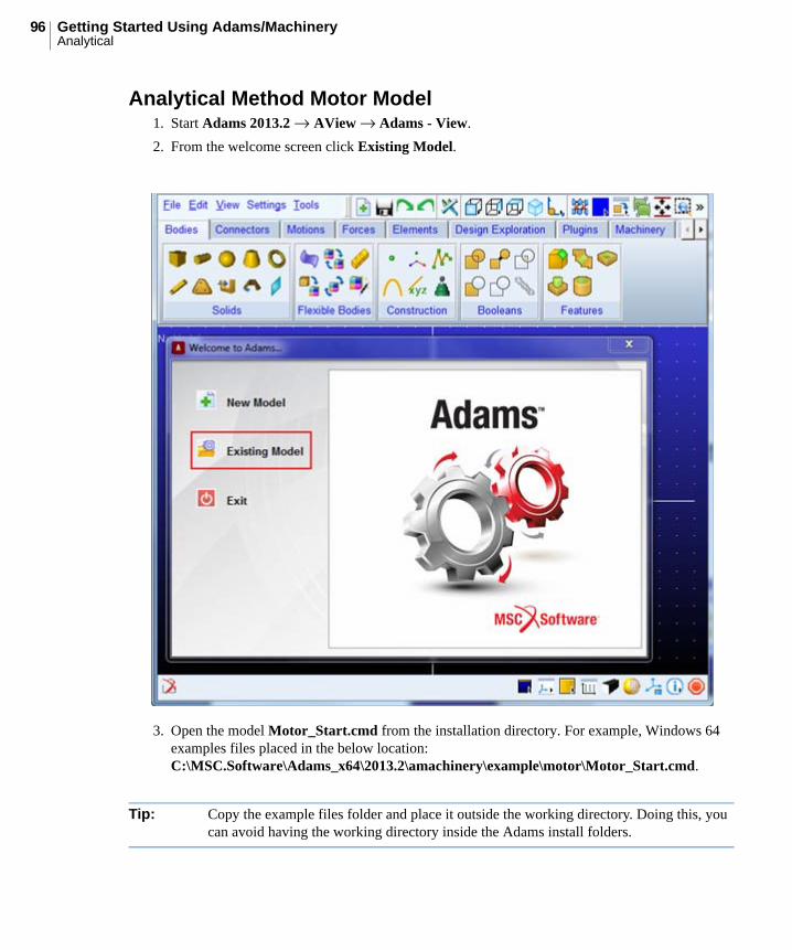
Analytical Method Motor Model1. Start Adams 2013.2 → AView → Adams - View.
2. From the welcome screen click Existing Model.
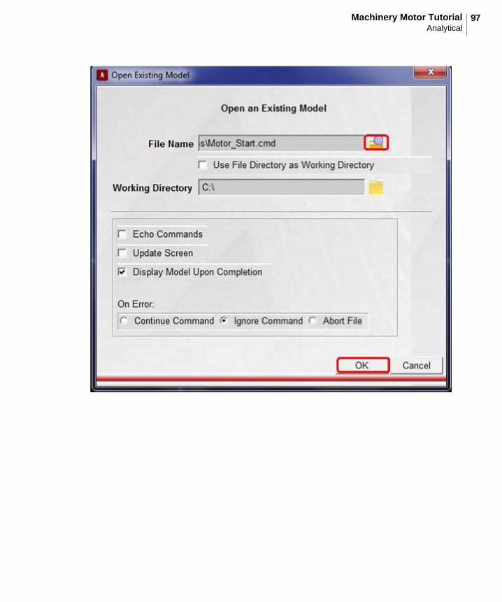
3. Open the model Motor_Start.cmd from the installation directory. For example, Windows 64 examples files placed in the below location:C:\MSC.Software\Adams_x64\2013.2\amachinery\example\motor\Motor_Start.cmd.
Tip: Copy the example files folder and place it outside the working directory. Doing this, you can avoid having the working directory inside the Adams install folders.
97Machinery Motor TutorialAnalytical

Getting Started Using Adams/MachineryAnalytical
98
4. The imported model will look like the one shown below.
a. It has:
• Crank geometry connected with revolute and spherical joint with ground and connecting rod
• Connecting rod is connected to rocker with universal joint
• Rocker is connected to ground with revolute joint
5. Click the Machinery tab on the Adams/View ribbon.
99Machinery Motor TutorialAnalytical
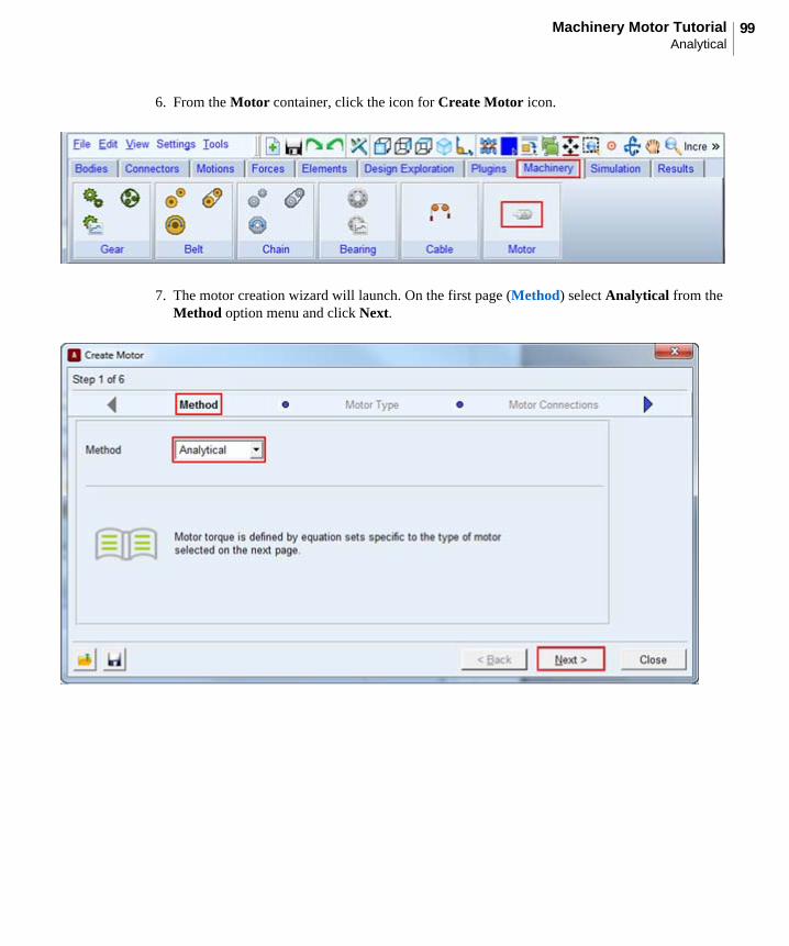
6. From the Motor container, click the icon for Create Motor icon.
7. The motor creation wizard will launch. On the first page (Method) select Analytical from the Method option menu and click Next.
Getting Started Using Adams/MachineryAnalytical
100
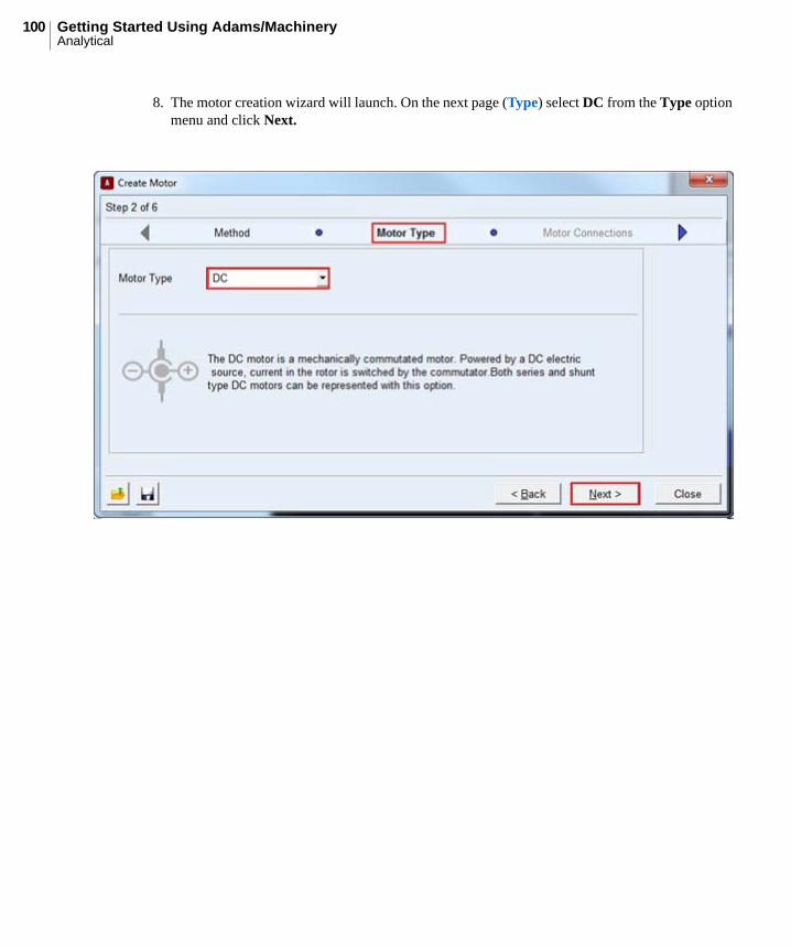
8. The motor creation wizard will launch. On the next page (Type) select DC from the Type option menu and click Next.
101Machinery Motor TutorialAnalytical
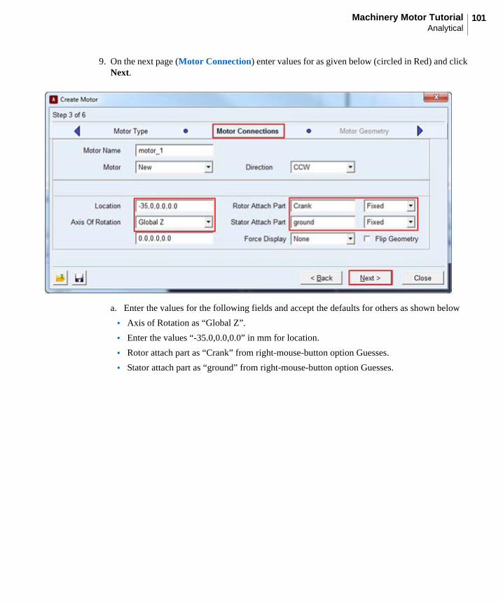
9. On the next page (Motor Connection) enter values for as given below (circled in Red) and click Next.
a. Enter the values for the following fields and accept the defaults for others as shown below
• Axis of Rotation as “Global Z”.
• Enter the values “-35.0,0.0,0.0” in mm for location.
• Rotor attach part as “Crank” from right-mouse-button option Guesses.
• Stator attach part as “ground” from right-mouse-button option Guesses.
Getting Started Using Adams/MachineryAnalytical
102
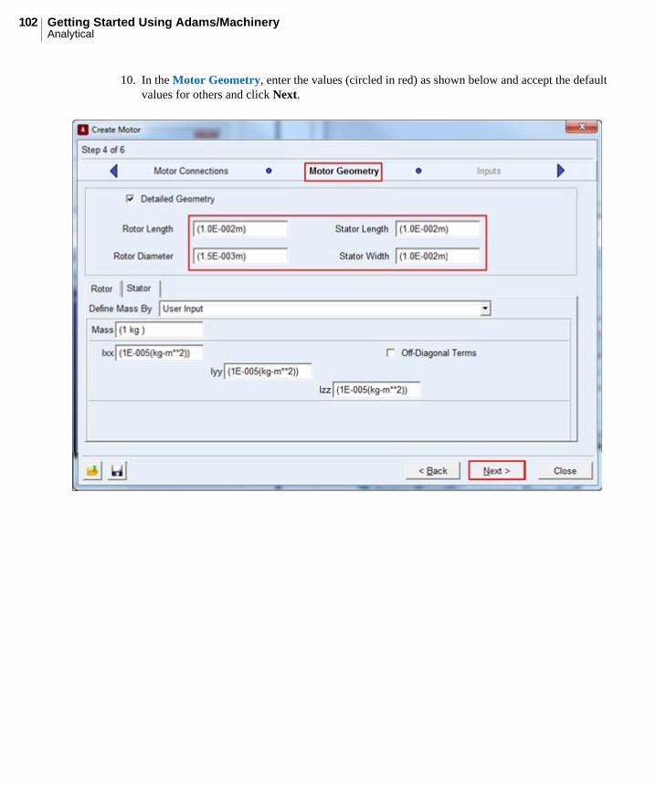
10. In the Motor Geometry, enter the values (circled in red) as shown below and accept the default values for others and click Next.
103Machinery Motor TutorialAnalytical
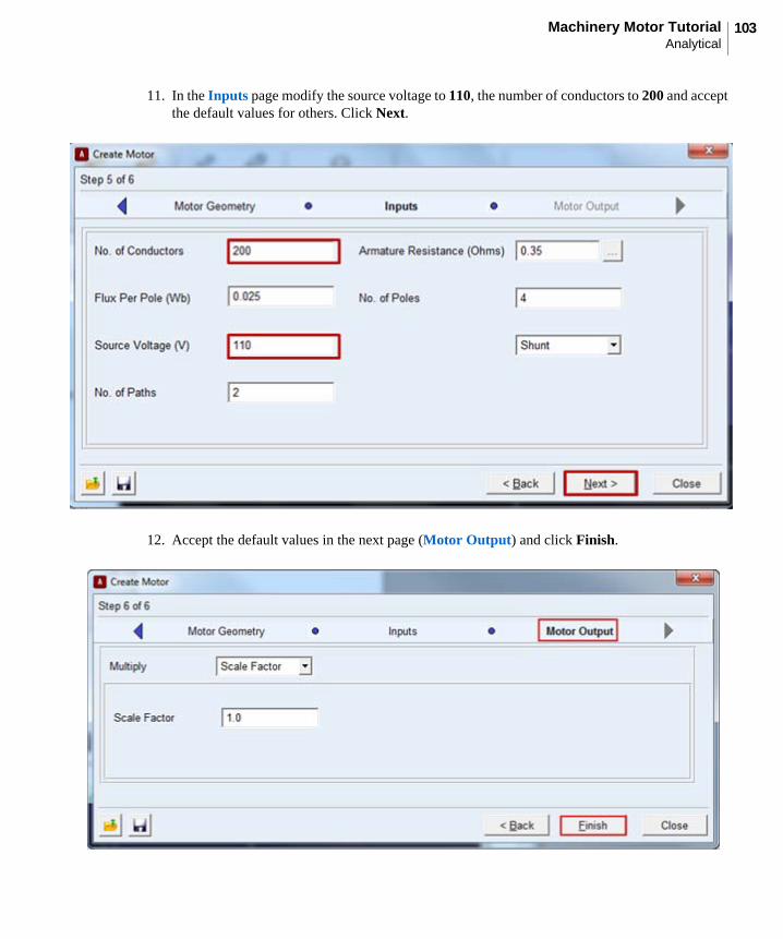
11. In the Inputs page modify the source voltage to 110, the number of conductors to 200 and accept the default values for others. Click Next.
12. Accept the default values in the next page (Motor Output) and click Finish.
Getting Started Using Adams/MachineryAnalytical
104
I
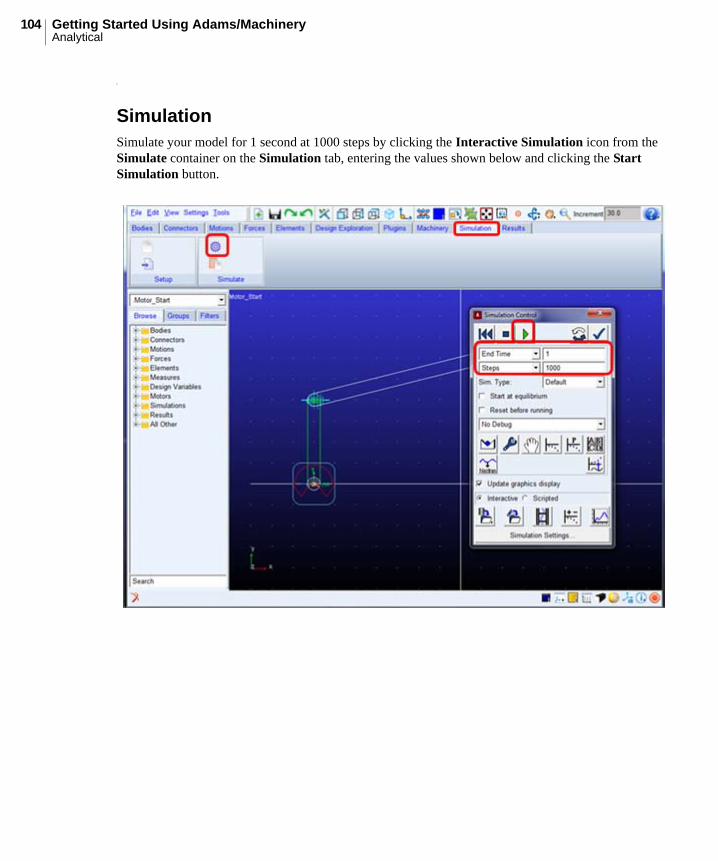
SimulationSimulate your model for 1 second at 1000 steps by clicking the Interactive Simulation icon from the Simulate container on the Simulation tab, entering the values shown below and clicking the Start Simulation button.
105Machinery Motor TutorialAnalytical
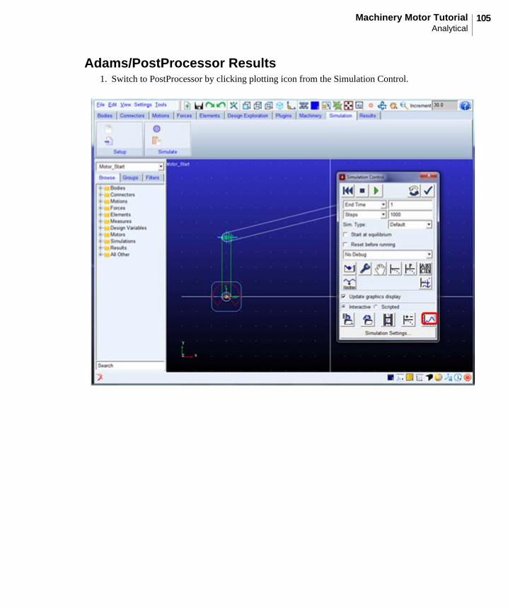
Adams/PostProcessor Results1. Switch to PostProcessor by clicking plotting icon from the Simulation Control.
Getting Started Using Adams/MachineryAnalytical
106
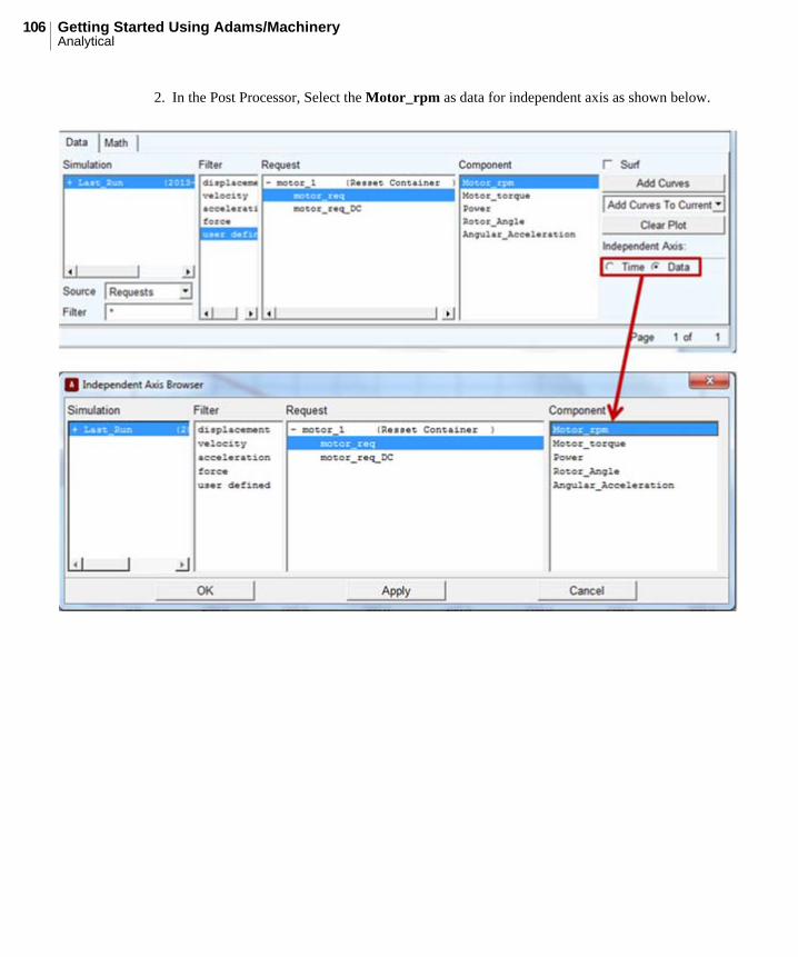
2. In the Post Processor, Select the Motor_rpm as data for independent axis as shown below.
107Machinery Motor TutorialAnalytical
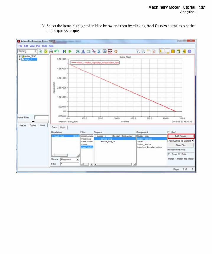
3. Select the items highlighted in blue below and then by clicking Add Curves button to plot the motor rpm vs torque.
Getting Started Using Adams/MachineryExternal
108
ExternalThe Adams/Machinery Motor module provides for the modeling of motor systems within the Adams/View environment. It supports multiple modeling methodology options including an external modeling method. This example shows how to create a motor using the external method from the minimal set of input parameters.
This chapter includes the following sections:
• What You Will Create
• External Method Motor Model
• Simulation
• Adams/PostProcessor Results
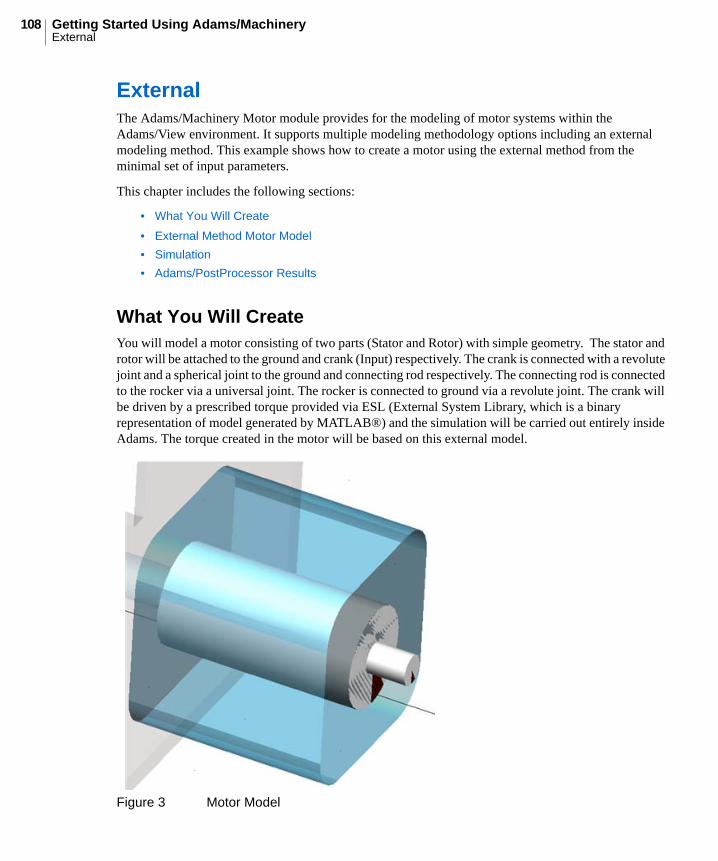
What You Will CreateYou will model a motor consisting of two parts (Stator and Rotor) with simple geometry. The stator and rotor will be attached to the ground and crank (Input) respectively. The crank is connected with a revolute joint and a spherical joint to the ground and connecting rod respectively. The connecting rod is connected to the rocker via a universal joint. The rocker is connected to ground via a revolute joint. The crank will be driven by a prescribed torque provided via ESL (External System Library, which is a binary representation of model generated by MATLAB®) and the simulation will be carried out entirely inside Adams. The torque created in the motor will be based on this external model.
Figure 3 Motor Model
109Machinery Motor TutorialExternal
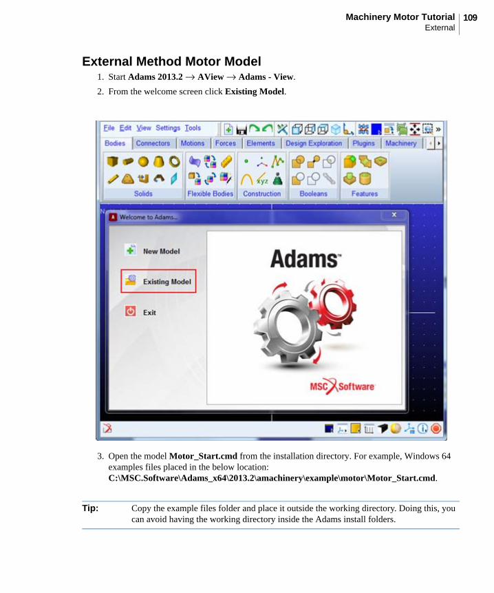
External Method Motor Model1. Start Adams 2013.2 → AView → Adams - View.
2. From the welcome screen click Existing Model.
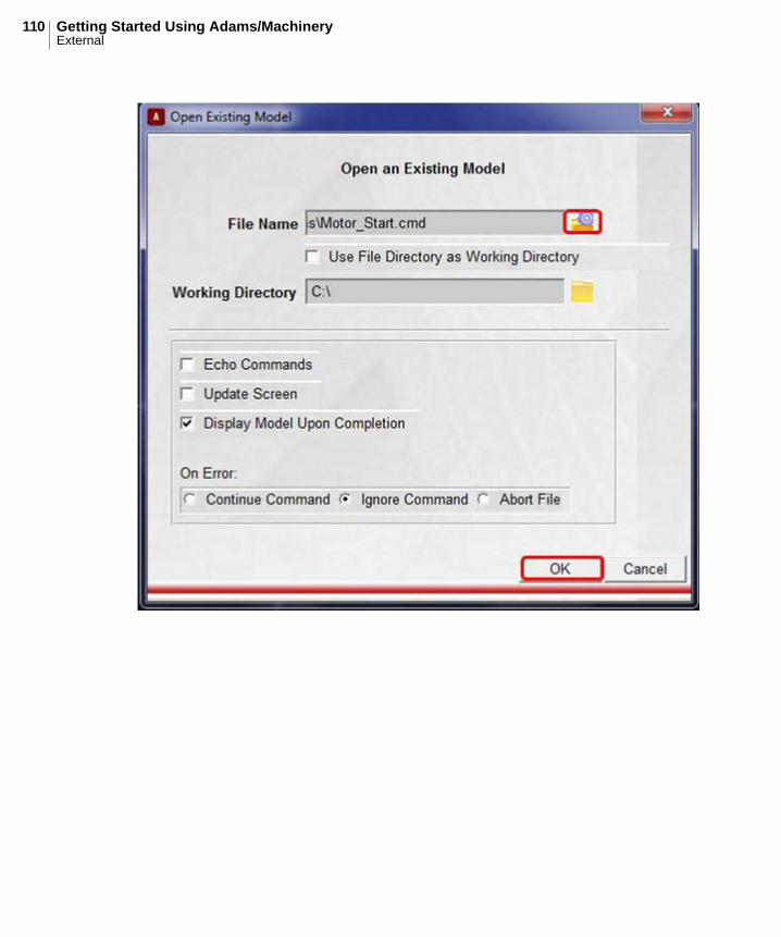
3. Open the model Motor_Start.cmd from the installation directory. For example, Windows 64 examples files placed in the below location:C:\MSC.Software\Adams_x64\2013.2\amachinery\example\motor\Motor_Start.cmd.
Tip: Copy the example files folder and place it outside the working directory. Doing this, you can avoid having the working directory inside the Adams install folders.
Getting Started Using Adams/MachineryExternal
110
111Machinery Motor TutorialExternal
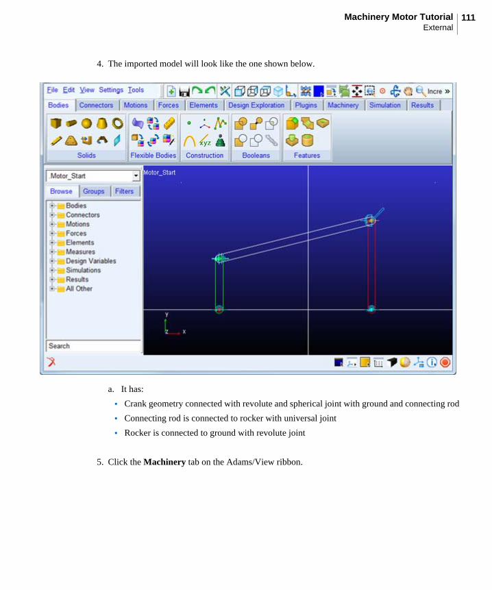
4. The imported model will look like the one shown below.
a. It has:
• Crank geometry connected with revolute and spherical joint with ground and connecting rod
• Connecting rod is connected to rocker with universal joint
• Rocker is connected to ground with revolute joint
5. Click the Machinery tab on the Adams/View ribbon.
Getting Started Using Adams/MachineryExternal
112
6. From the Motor container, click the icon for Create Motor icon.
7. The motor creation wizard will launch. On the first page (Method) select External from the Method option menu and click Next.
113Machinery Motor TutorialExternal
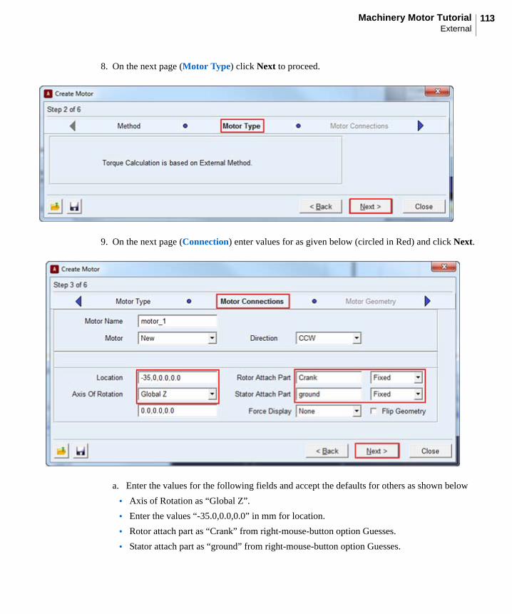
8. On the next page (Motor Type) click Next to proceed.
9. On the next page (Connection) enter values for as given below (circled in Red) and click Next.
a. Enter the values for the following fields and accept the defaults for others as shown below
• Axis of Rotation as “Global Z”.
• Enter the values “-35.0,0.0,0.0” in mm for location.
• Rotor attach part as “Crank” from right-mouse-button option Guesses.
• Stator attach part as “ground” from right-mouse-button option Guesses.

Getting Started Using Adams/MachineryExternal
114
10. In the Motor Geometry, enter the values (circled in red) as shown below and accept the default values for others and click Next.
115Machinery Motor TutorialExternal
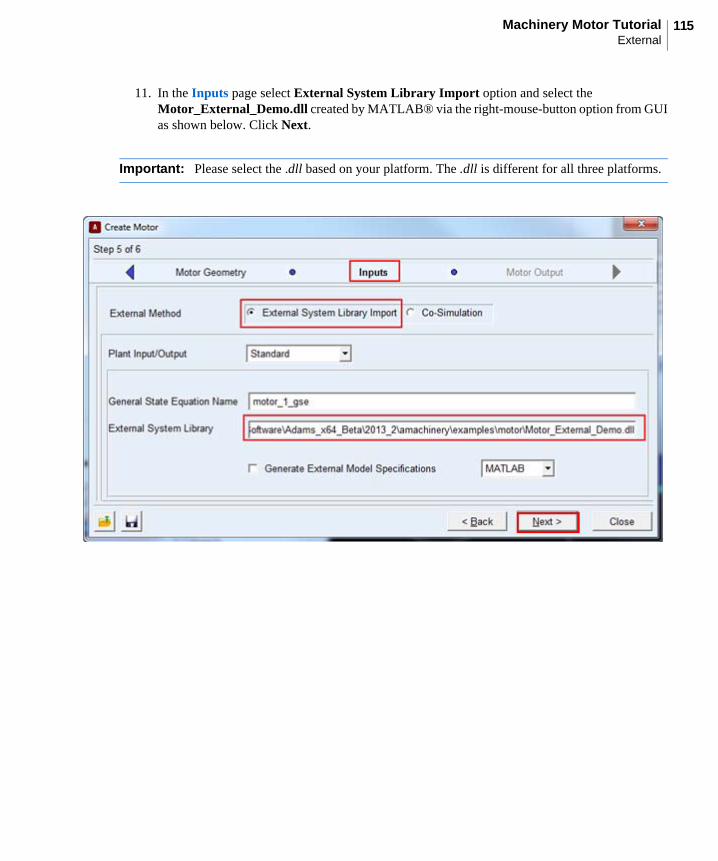
11. In the Inputs page select External System Library Import option and select the Motor_External_Demo.dll created by MATLAB® via the right-mouse-button option from GUI as shown below. Click Next.
Important: Please select the .dll based on your platform. The .dll is different for all three platforms.
Getting Started Using Adams/MachineryExternal
116
117Machinery Motor TutorialExternal
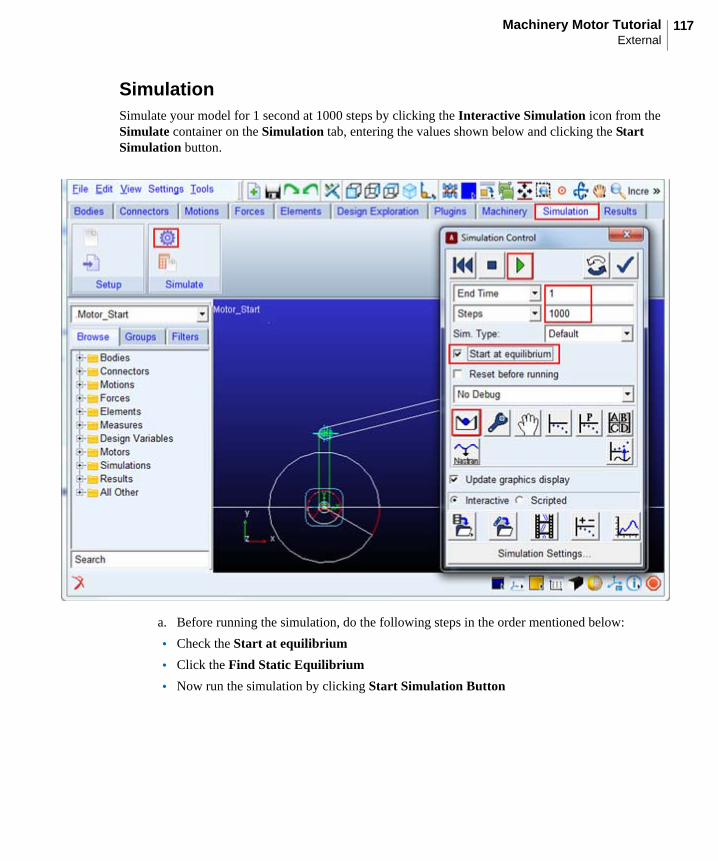
SimulationSimulate your model for 1 second at 1000 steps by clicking the Interactive Simulation icon from the Simulate container on the Simulation tab, entering the values shown below and clicking the Start Simulation button.
a. Before running the simulation, do the following steps in the order mentioned below:
• Check the Start at equilibrium
• Click the Find Static Equilibrium
• Now run the simulation by clicking Start Simulation Button
Getting Started Using Adams/MachineryExternal
118
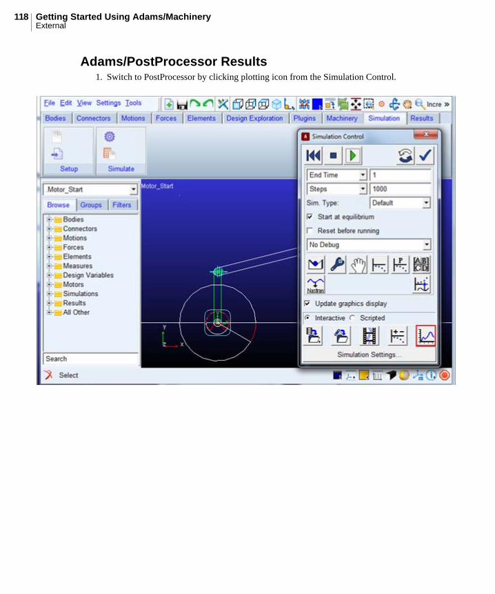
Adams/PostProcessor Results1. Switch to PostProcessor by clicking plotting icon from the Simulation Control.
119Machinery Motor TutorialExternal
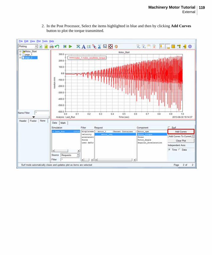
2. In the Post Processor, Select the items highlighted in blue and then by clicking Add Curves button to plot the torque transmitted.

Getting Started Using Adams/MachineryExternal
120