tutorial t9: technology machinery engineers need to know
TRANSCRIPT

SESSION 1 AND SESSION 2
TECHNOLOGY MACHINERY
ENGINEERS NEED TO KNOW TO
WORK EFFECTIVELY SUBSEA

• More and more equipment is being installed subsea. These include valves
and manifolds, chokes, pumps, compressors, separators, etc. These
installation are needed to effectively produce underwater oil and gas
deposits. As water becomes deeper, it becomes less effective to install all
the equipment above the water’s surface. These applications are occurring
in almost all the waters of the world.
• The skills required to work subsea in this manner are a combination of the
basic mechanical skills of machinery equipment specialists coupled to the
skills of subsea engineers. Either subsea specialists have to learn
hardware engineering skills, or vice versa.
• This tutorial attempts to present a part of subsea engineering skills to
machinery specialists in order to both educate them in some of these skills
and to enlighten them to the required additions to their ski8ll set.
References are provided. Liberal use is made of graphics, figures, and
animations.
Overview

• There are two sessions of this tutorial.
• Dr. Zenon Medina-Cetina of Texas A&M will
start each with a “Big Picture” view of the
issue.
• Session 1 will be presented by Dag
Elvebakken and Jonah Margulis of Aker
Solutions.
• Session 2 will be presented by Michael
Mancuso of OneSubsea.
Tutorial Organization

• The presentation of the 2 Sessions will be
somewhat different.
• The overall content will contain the same
or similar features.
Content

• A “Big Picture Walk Through on” Offshore Deepwater E&P Systems
• History of Subsea and the importance of the growth of subsea as a source of oil and
gas moving forward.
• What does a typical subsea entire system look like? Size, scale, weight.
• Video, animations, and pictures of installation sequences, view of reservoir and entire
system.
• Describe pumps and pump systems, including different pump technologies.
Marininized units, pump modules.
• Typical standards and testing required for meeting subsea customer demands and
regulatory requirements.
• What separates subsea equipment and equipment form topsides, show examples.
• Emphasize focus on reliable, robust and redundant systems. Modularization, simple
and robust interfaces, ROV access.
• Educational Road Map to Subsea.
Topics

A "Big Picture Walk Through"
OFFSHORE DEEPWATER
SYSTEMS
Stochastic Geomechanics Laboratory
SGL at Texas A&M University
Zenon Medina-Cetina
• Dr. Medina-Cetina is Assistant Professor in the
Civil Engineering Department at Texas A&M
University, with a joint appointment in the
Petroleum Engineering Department.
• He leads the Stochastic Geomechanics
Laboratory SGL, where both probabilistic and
geomechanical applications are explored for
improving the uncertainty quantification inherent
to mainly energy-based projects, both onshore
and offshore.
• He is a fellow of the Society for Underwater
Technology SUT, and is Chair of the Offshore
Site Investigation and Geotechnics of SUT,
which gathers a geo-leaders in Oil & Gas E&P.
Author
Department of Civil Engineering
Texas A&M University
CE/TTI 702 D
3136 TAMU
College Station, TX

Offshore Deepwater Systems:
The Big Picture
Upstream
D o w n s t r e a m
Exploration Subsea
Engineering Production
Transportation Refining Storage Distribution Marketing
…
…

Offshore Deepwater Systems
Key Areas of Offshore Deepwater
Systems
• Site Characterization
• Metocean
• Flow Assurance
• Design of Infrastructure
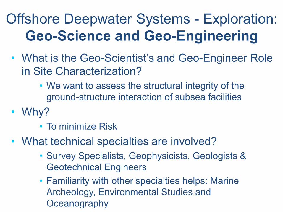
Offshore Deepwater Systems - Exploration:
Geo-Science and Geo-Engineering
• What is the Geo-Scientist’s and Geo-Engineer Role
in Site Characterization?
• We want to assess the structural integrity of the
ground-structure interaction of subsea facilities
• Why?
• To minimize Risk
• What technical specialties are involved?
• Survey Specialists, Geophysicists, Geologists &
Geotechnical Engineers
• Familiarity with other specialties helps: Marine
Archeology, Environmental Studies and
Oceanography

Offshore Deepwater Systems - Exploration:
Flow Assurance
Sea surface
temperature Sea surface
temperature
• Flow Assurance can be characterized as:
– The ability to produce fluids reliably & economically from the reservoir to a production facility over life of the field in any environment
– Assurance that well fluids can be delivered from the wellhead to the final production facility under all operating conditions.
– Also the ability to deliver produced fluids via export lines, trunklines or transportation lines to process facilities
• This ability is influenced by: – Pressure
– Temperature
– Fluid composition
• We really mean: “Flow Assurance and Operability”

Offshore Deepwater Systems
Educational Road Map
to Subsea Engineering

Offshore Deepwater Systems Reservoir Analysis
Site Characterization
Field Architecture
Risk Assessment: Social, Economical, Environmental
Controls
Flow Assurance
Subsea Facilities
Floating Systems
Pipelines
Moorings
Risers
Safety
Installation and Commissioning
Monitoring Integrity
Decommissioning
Risk Management

© 2014
INTRODUCTION TO
ROTATING MACHINERY
SUBSEA
TECHNOLOGY MACHINERY ENGINEERS NEED TO
KNOW TO WORK SUBSEA EFFECTIVELY
© 2014
Authors
3 June, 2014 Introduction to Rotating Machinery Subsea Slide 2
■ Dag Elvebakken
Dag Elvebakken is a mechanical engineer (Msc.) who has
been working with subsea pumps for Aker Solutions the last 8
years. Since his start with the company he has been working
within all of Aker Solutions boosting and compression
projects delivered out of Norway. His main focus areas are
pump system design and testing . Currently he is working as
a Technology Lead for Aker Solutions Pump Systems
department, located at Tranby a few miles west of Oslo,
Norway. You can reach him at
■ Jonah Margulis
Jonah Margulis is the Director of Business Development and
Sales for Aker Solutions. He obtained his engineering degree
from Lafayette College in Easton, Pennsylvania and MBA
with an Energy Management certificate from the University of
Houston. He has worked in the pump industry since 2001 and
been involved in subsea multiphase pump technology
development since 2008. Jonah serves as an active member
of the API 17X and 17S working groups. He currently resides
in Houston with his wife Milena and young daughter Rose.
You can reach him at [email protected]

© 2014
Tutorial Scope
■ Focus ■ Introduction
■ Background for
boosting/injection
■ High level overview of subsea
production system
■ Rotating machinery located at
the seabed, with main focus: ■ Centrifugal seabed pumps
■ Enabling systems
■ Briefly cover subsea
compression
■ Pumps inside well (downhole)
are not included
3 June, 2014 Introduction to Rotating Machinery Subsea Slide 3
© 2014
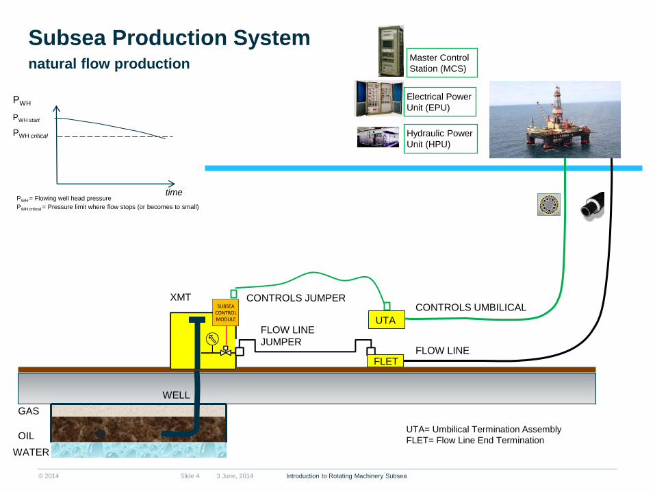
Subsea Production System
3 June, 2014 Introduction to Rotating Machinery Subsea Slide 4
GAS
OIL
WATER
SUBSEA CONTROL MODULE
XMT
FLOW LINE
CONTROLS UMBILICAL
FLOW LINE
JUMPER
Electrical Power
Unit (EPU)
Hydraulic Power
Unit (HPU)
Master Control
Station (MCS)
time
PWH
PWH critical
natural flow production
PWH start
UTA
FLET
CONTROLS JUMPER
WELL
UTA= Umbilical Termination Assembly
FLET= Flow Line End Termination
PWH = Flowing well head pressure
PWH critical = Pressure limit where flow stops (or becomes to small)

© 2014
Subsea Production System
3 June, 2014 Introduction to Rotating Machinery Subsea Slide 5
GAS
OIL
WATER
SUBSEA CONTROL MODULE
XMT CONTROLS UMBILICAL
FLOW LINE
JUMPER
Electrical Power
Unit (EPU)
Hydraulic Power
Unit (HPU)
Master Control
Station (MCS)
POWER CABLE
Variable Speed
Drive (VSD)
Barrier Fluid
HPU
SCM
BOOST PUMP
Boosting
time
UTA
FLET
WELL
UTA
UTA= Umbilical Termination Assembly
FLET= Flow Line End Termination
PWH
PWH critical
PWH start
PWH = Flowing well head pressure
PWH critical = Pressure limit where flow stops (or becomes to small)
Note: Figure is a simplification.
In a real application many other
factors must be considered and
will influence system and
philosophies.
FLOW LINE

© 2014
Subsea Production System
3 June, 2014 Introduction to Rotating Machinery Subsea Slide 6
GAS
OIL
SUBSEA CONTROL MODULE
Electrical Power
Unit (EPU)
Hydraulic Power
Unit (HPU)
Master Control
Station (MCS)
Variable Speed
Drive (VSD)
Barrier Fluid
HPU
SCM
BOOST PUMP
XMT WI XMT
SCM
UTA UTA
POWER&CONTROLS
UMBILICAL
SCM
WI PUMP
Variable Speed
Drive (VSD)
time
FLET
UTA = Umbilical Termination Assembly
FLET = Flow Line End Termination
WATER WI = Water Injection
PWH
PWH critical
PWH start
PWH = Flowing well head pressure
PWH critical = Pressure limit where flow stops (or becomes to small)
Boosting &
Water Injection
Note: Figure is a simplification.
In a real application many other
factors must be considered and
will influence system and
philosophies.
FLOW LINE

© 2014 3 June, 2014 Introduction to Rotating Machinery Subsea Slide 7
Subsea Production System

© 2014
Subsea Production System
3 June, 2014 Introduction to Rotating Machinery Subsea Slide 8
Manifold
Pump Station
XMT
Well jumper
Flowline
Umbilical
Umbilical (power)

© 2014
Background - Why & Where
■ Rotating machinery subsea in the
form of pumps and compressors
are used to increase recovery of
hydrocarbons ■ By adding energy to the well
stream (Boosting / Compression)
■ By adding energy to a fluid
(water or gas) so it can be
injected into the reservoir.
(Injection)
■ In combination with subsea
processing equipment, e.g.
down-stream a separator or
scrubber
3 June, 2014 Introduction to Rotating Machinery Subsea Slide 9

© 2014
Easy oil is gone; huge values remains
3 June, 2014 Slide 10
RF
~ 60%
RF
~ 35%
Source: Aker Solutions; Chevron; OD ”Økt Utvinning På Norsk Kontinentalsokkel”; IntecSea poster 2011; Oistein Bøe “DOT IOR
Workshop
Increased Subsea
Recovery Factor
6 % 10 %
40 %
60 %
■ 1% IOR on NCS = USD 50 BN value creation
■ Short pay back: 30 days @ 20 000 bopd increase
Tordis Tyrihans GOM
single
phase
potential
GOM
multi
phase
potential
IOR Examples
Introduction to Rotating Machinery Subsea

© 2014 3 June, 2014 Slide 11
Why install subsea boosting?
■ Increased production through life
■ Increased production late life
■ Reduced development cost
■ Enables development and production
of low pressure reservoirs
■ Makes deep water development
possible
Enhanced Production (Early Boosting)
Boosted Production
Ra
te [b
pd
]
Time [years]
Normal, Unboosted production
Extended Production (Late Boosting)
Boosted Production
Time [years]
Rate
[b
pd
] Normal,
Unboosted production
Reduced OPEX
Delayed CAPEX
Introduction to Rotating Machinery Subsea

© 2014
Background - Why & Where
3 June, 2014 Introduction to Rotating Machinery Subsea Slide 12

© 2014
The Subsea Challenges
3 June, 2014 Introduction to Rotating Machinery Subsea Slide 13
Long Distances step-out from a few up to
above 100 miles
Environmental Generally zero-tolerance for
emissions
Complex Reservoirs High pressures, up to > 15 000 psi
High temperatures, up to > 350 °F
Deep wells, Heavy oil
Corrosive fluids, Solids, Low permeability
Deep Waters down to 10 000 ft
external pressures above 4000 psi

© 2014 3 June, 2014 Slide 14
Challenges of going subsea with rotating machinery…
■ Reliability is key! ■ Cost of intervention is very high
■ Cost of lost production may be even higher
■ Reliability challenges ■ Target of 5 years or more between interventions
■ Design life 20 – 30 years
■ Demanding process fluids -> corrosive, solids
■ High temperatures and pressures in process fluid
■ Control and monitoring; remote location and demanding environment
■ Range of operation
■ Maintainability ■ Only access by ROV (Remote Operated Vehicle). Divers are used in a few cases
■ Need to mobilize expensive surface vessel to inspect by ROV or replace failed
units
■ Environmental ■ Risk of emissions of hydrocarbons (or other toxic fluids) to sea
■ Consequences may be catastrophic and unacceptable
■ Generally zero-tolerance for hydrocarbon emissions (even for very small volumes)
Introduction to Rotating Machinery Subsea

© 2014
What – Pump Technologies for use subsea
■ Centrifugal (Roto-dynamic) Pumps ■ Single phase
■ Radial impellers, multi-stage
■ Multiphase ■ Multi-stage, mixed flow impellers
■ Helico-axial
■ Hybrid ■ Multi-stage, combination impellers of different technologies
■ Medium gas tolerance
■ Positive displacement ■ Twin-screw (Multiphase)
3 June, 2014 Introduction to Rotating Machinery Subsea Slide 15
Radial Flow
Mixed Flow Helico-axial*
Twin-screw
+ or +
Source: “Centrifugal
Pumps”, 2nd edition,
fig. 13.22, by J.F.
Gülich

© 2014
What – Pressure generation vs GVF - capabilities
3 June, 2014 Introduction to Rotating Machinery Subsea Slide 16
0
50
100
150
200
250
300
350
0 10 20 30 40 50 60 70 80 90 100
Pu
mp
diffe
ren
tial p
ressu
re [ba
r]
GVF [%] @ Pump Inlet
LiquidBooster™
HybridBooster™
MultiBooster™ 8-Stage
MultiBoosterTM LiquidBoosterTM HybridBooster TM
© 2014
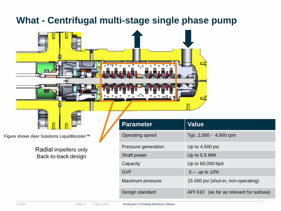
What - Centrifugal multi-stage single phase pump
3 June, 2014 Introduction to Rotating Machinery Subsea Slide 17
Radial impellers only
Back-to-back design
Figure shows Aker Solutions LiquidBooster™
Parameter Value
Operating speed Typ. 2,000 - 4,000 rpm
Pressure generation Up to 4,500 psi
Shaft power Up to 5.5 MW
Capacity Up to 60,000 bpd
GVF 0 – up to 10%
Maximum pressure 15 000 psi (shut-in, non-operating)
Design standard API 610 (as far as relevant for subsea)

© 2014 3 June, 2014 Slide 18
Pump Inlet Pump Outlet
1 2 3 4 8 7 6 5
What - Centrifugal multi-stage single phase pump
Introduction to Rotating Machinery Subsea

© 2014
What - Centrifugal multi-stage hybrid pump
3 June, 2014 Introduction to Rotating Machinery Subsea Slide 19
Radial flow impellers - Mixed flow impellers
Opposed impeller design
Capable of up to ca 50 % GVF
Figure shows Aker Solutions HybridBooster™

© 2014
What - Centrifugal multi-stage multi-phase pump
3 June, 2014 Introduction to Rotating Machinery Subsea Slide 20
Mixed flow impellers
Back-to-back design
Figure shows
Aker Solutions
MultiBooster™
Parameter Value
Operating speed Typ. 3000 - 6000 rpm
Pressure generation Up to 200 bar/ 2900 psi
Shaft power Up to 5.5 MW
Capacity Up to 220,000 bpd
GVF 0 – above 95%
Maximum pressure 15 000 psi (shut-in, non-operating)
Design standard API 610 (as far as relevant for subsea)
© 2014
What - Centrifugal multi-stage multi-phase pump
3 June, 2014 Introduction to Rotating Machinery Subsea Slide 21
MULTIBOOSTER VIDEO
© 2014
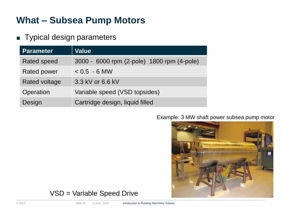
What – Subsea Pump Motors
■ Typical design parameters
3 June, 2014 Introduction to Rotating Machinery Subsea Slide 22
Parameter Value
Rated speed 3000 - 6000 rpm (2-pole) 1800 rpm (4-pole)
Rated power < 0.5 - 6 MW
Rated voltage 3.3 kV or 6.6 kV
Operation Variable speed (VSD topsides)
Design Cartridge design, liquid filled
VSD = Variable Speed Drive
Example: 3 MW shaft power subsea pump motor

© 2014
What – Subsea Pump Motors
■ Subsea motors are generally of cartridge design
■ For subsea pumping applications both induction motors and permanent
magnet motors are used
■ Both form wound and fully insulated cable wound stators are used
■ Typically twin-screw pumps use 4-pole motors while the faster rotating
centrifugal pumps use 2-pole motors
■ To provide lubrication, cooling and preventing ingress of process fluid
subsea pump motors are liquid filled
3 June, 2014 Introduction to Rotating Machinery Subsea Slide 23
© 2014
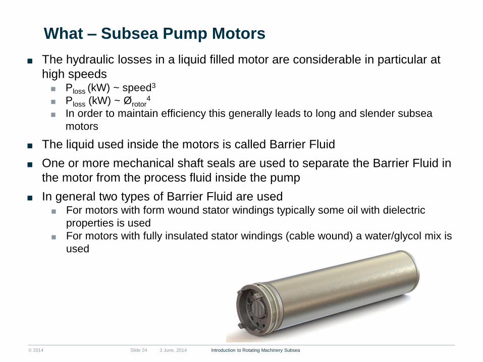
What – Subsea Pump Motors
■ The hydraulic losses in a liquid filled motor are considerable in particular at
high speeds ■ Ploss (kW) ~ speed3
■ Ploss (kW) ~ Ørotor4
■ In order to maintain efficiency this generally leads to long and slender subsea
motors
■ The liquid used inside the motors is called Barrier Fluid
■ One or more mechanical shaft seals are used to separate the Barrier Fluid in
the motor from the process fluid inside the pump
■ In general two types of Barrier Fluid are used ■ For motors with form wound stator windings typically some oil with dielectric
properties is used
■ For motors with fully insulated stator windings (cable wound) a water/glycol mix is
used
3 June, 2014 Introduction to Rotating Machinery Subsea Slide 24

© 2014
What – Subsea Pump Motors
3 June, 2014 Introduction to Rotating Machinery Subsea Slide 25
Type Liquid filled (Water/Glycol) induction motor
Number of poles 2
Rated Voltage 6600 V
Rated Frequency 100 Hz
Rated Power 6000 kW
Rated Speed 6000 rpm
Stator technology Cable wound
Maximum Pressure 15 000 psi (shut-in, motor at stand-still)
Temperature rating Class H (180°C, IEC 60085)
Circulation pump
Stator
Rotor
Stator winding
Example: High speed subsea motor
Tilt-pad radial
bearing Bearing Housing
Barrier fluid
from cooler
(cold)
Barrier fluid to
cooler (warm)

© 2014
What – Pressure casings
■ Pressure casings ■ Main barrier between sea
water and process fluid
■ Typical design pressures from
5 kpsi to 15 kpsi
■ Example: Design and
qualification of High Pressure
(HP) pump & motor casing ■ Design pressure 13 500 psi =
931 bar
■ Test pressure = 20 250 psi =
1396 bar
■ Internal diameter 30 inches
■ Wall thickness ca. 7 inches
■ Weight ca. 15 tonne/casing
3 June, 2014 Introduction to Rotating Machinery Subsea Slide 26

© 2014
What – Subsea Pressure Casings
■ High pressure casing manufacturing/testing
3 June, 2014 Introduction to Rotating Machinery Subsea Slide 27
Forging Pre machining Cladding
Welding Final machining Assembly for test
Inspection Painting Fiinal assembly
Pressure testing
Design pressure 13 500 psi = 931 bar
Test pressure = 20 250 psi = 1396 bar API 6A, API 17D and EN13445 (1,5x)

© 2014 3 June, 2014 Slide 28
What – Subsea Pump & Motor assembly
Motor assembly
Pump & Motor Unit
Motor pressure casing Motor cartridge
Pump pressure casing Pump cartridge Pump assembly
Introduction to Rotating Machinery Subsea

© 2014
What – Pump Module schematic (Single phase pump)
3 June, 2014 Introduction to Rotating Machinery Subsea Slide 29

© 2014
What –Pump Module
■ The subsea pumps are
generally integrated into a
module
■ The module has interfaces
which allow operation by a
Remote Operated Vehicle
(ROV) and for installation
and retrieval
■ The figures shows example
of main units and interfaces
3 June, 2014 Introduction to Rotating Machinery Subsea Slide 30

© 2014 3 June, 2014 Introduction to Rotating Machinery Subsea Slide 31
What –Pump Module

© 2014
What – Barrier Fluid System
■ Objective ■ Lubrication and cooling of motor
■ To prevent ingress of process fluid into motor
■ Maintain controlled pressure difference over mechanical shaft seals
■ Re-supply of barrier fluid to motor due to leakage over mechanical
seal and dumping by pressure regulating valve (PVR)
■ Schematic below shows high-level principle of system
3 June, 2014 Introduction to Rotating Machinery Subsea Slide 32
PVR= Pressure Volume Regulator
(Mechanical hydraulic pressure regulating valve)
© 2014 Slide 33
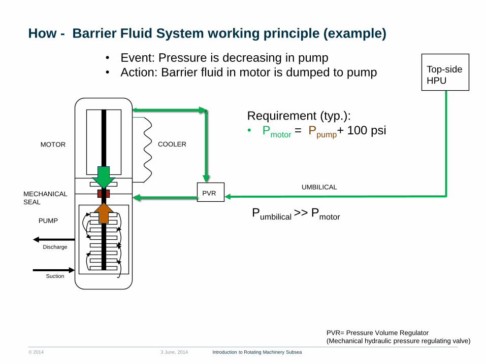
How - Barrier Fluid System working principle (example)
PVR
Top-side
HPU
Discharge
Suction
3 June, 2014
COOLER MOTOR
PUMP
MECHANICAL
SEAL
UMBILICAL
Introduction to Rotating Machinery Subsea
PVR= Pressure Volume Regulator
(Mechanical hydraulic pressure regulating valve)
• Event: Pressure is decreasing in pump
• Action: Barrier fluid in motor is dumped to pump
Requirement (typ.):
• Pmotor = Ppump+ 100 psi
Pumbilical >> Pmotor

© 2014 Slide 34
How - Barrier Fluid System working principle (example)
PVR
Top-side
HPU
Discharge
Suction
3 June, 2014
COOLER MOTOR
PUMP
MECHANICAL
SEAL
UMBILICAL
Introduction to Rotating Machinery Subsea
PVR= Pressure Volume Regulator
(Mechanical hydraulic pressure regulating valve)
• Event: Pressure is increasing in pump
• Action: Barrier fluid is supplied from umbilical to motor
Requirement (typ.):
• Pmotor = Ppump+ 100 psi
Pumbilical >> Pmotor

© 2014
What – Pump station
■ Pump station with main interfaces
3 June, 2014 Introduction to Rotating Machinery Subsea Slide 36
Process connection
ROV - panel
HV- Wet-mate
connections
ROV - panel
ROV - panel

© 2014
What – Pump station modularisation
3 June, 2014 Introduction to Rotating Machinery Subsea Slide 37
Transformer
Module
Pump Module
Manifold Module
Base frame and
suction anchor

© 2014
Pump Station process flow
3 June, 2014 Introduction to Rotating Machinery Subsea Slide 38
MultiBoosterTM
Station
To Host
FCU
UT
UT
From Wells
)(FT
FCU = Flow Conditioning Unit
GVF = Gas Volume Fraction
Example shows typical process flow diagram for a Multi
Phase Pump system
Generally centrifugal MPP’s require a Flow
Conditioning Unit (FCU) upstream to buffer slugs and
level out the variations in GVF before the pump
There is also typically a re-circulation loop with a
choke valve for (typ.) start-up and adjustment of
operating point

© 2014
What – Subsea interfaces Process connections
Example: Clamp connectors
3 June, 2014 Introduction to Rotating Machinery Subsea Slide 39
• Mono or multi bore
• Horizontal or vertical assemblies
• Metal to metal seals
• ISO 13628-4/7 & ASME VIII div 2
Example: Clamp Connector Sizes
• 6in clamp – bore size 2” to 6”
• 12in clamp – bore size 6” to 12”
• 16in clamp – bore size 12” to 16”
• 22in clamp – bore size 16” to 22”
• 28in clamp – bore size 22” to 28”
Seal
IB Hub
OB Hub

© 2014 3 June, 2014 Slide 40
What - Umbilical
■ The subsea system is connected to the host
facility through umbilical(s)
■ This allows for the supply of: ■ Controls power
■ Communication
■ Chemicals
■ Hydraulics
■ High-voltage power for pumps/compressors (and other
applications, e.g. heating of pipelines)
■ Barrier fluid to subsea motors
Introduction to Rotating Machinery Subsea

© 2014
What – Pump Control and Condition Monitoring
Example architecture
3 June, 2014 Introduction to Rotating Machinery Subsea Slide 41

© 2014
Electrical Power Unit (EPU) Hydraulic Power Unit (HPU) Master Control Station (MCS)
Control System - Topside Equipment
Barrier Fluid HPU (BF HPU)
Subsea Production System Control
Pump System Control addition
3 June, 2014 Introduction to Rotating Machinery Subsea Slide 42

© 2014
Control System Subsea Equipment
Subsea Control Modules (SCM) Subsea Distribution Unit (SDU)
SCM Mounting Base
3 June, 2014 Introduction to Rotating Machinery Subsea Slide 43

© 2014
What - Low speed sensors subsea (typ. 1 Hz bandwidth)
■ Pressure & Temperature
■ In process fluid ■ In barrier fluid ■ In MEG/MeOh
■ Single phase flow meter ■ V-cone or Venturi
■ Multi phase flow meter ■ Cross-correlation of several inputs ■ Venturi, electrical impedance &
gamma ray ■ Multi-variable output
■ Earth fault
■ Line Voltage & Current ■ Average values (RMS)
■ Motor stator winding temperature
■ Leak detectors ■ Acoustic ■ Capacitive
Introduction to Rotating Machinery Subsea
MEG= Ethylene Glycol
MeOh = Methanol
3 June, 2014 Slide 44

© 2014
What - High-speed sensors: Accelerometers
Technology:
• Accelerometers are located outside the
pressure casings
• Aker Solutions was first to include
accelerometers on subsea pumps and
motors in 2005.
Location typical:
Motor NDE bearing: 1 axis, radial
Motor DE bearing: 1 axis, radial
Pump DE bearing: 2 axis, radial + axial
Pump NDE bearing: 1 axis, radial
Introduction to Rotating Machinery Subsea 3 June, 2014 Slide 45

© 2014
What – Subsea interfaces
■ Wet-mate connections for control system ■ Control system power (typ. < 1kV)
■ Communications ■ Electrical
■ Optical
■ Hydraulic couplers
3 June, 2014 Introduction to Rotating Machinery Subsea Slide 46

© 2014
Subsea Interconnection Flying Leads (Jumpers)
Electrical Flying Lead –
showing ROV connectors
Hydraulic Flying Lead –
showing ROV stab-plates (MQC plates)
Stabplate
3 June, 2014 Introduction to Rotating Machinery Subsea Slide 47
MQC =Multiple Quick Connect

© 2014
XMT
Multiplexed Electro/Hydraulic Control
MCS EPU HPU
SEM
PT
SCM
Comms. Power Supply Return
Umbilical
TT
Px
MCS – Master Control Station
EPU – Electrical Power Unit
HPU – Hydraulic Power unit
SCM – Subsea Control Module
SEM – Subsea Electronics Module
XMT – Xmas Tree
PT – Pressure Transmitter
TT – Temperature Transmitter
3 June, 2014 Introduction to Rotating Machinery Subsea Slide 48

© 2014
What – Subsea Power long step-out systems
3 June, 2014 Introduction to Rotating Machinery Subsea Slide 49
© 2014 3 June, 2014 Introduction to Rotating Machinery Subsea Slide 50
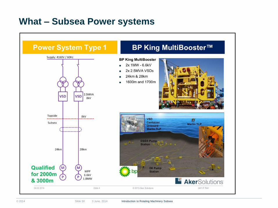
What – Subsea Power systems
© 2014 3 June, 2014 Introduction to Rotating Machinery Subsea Slide 51
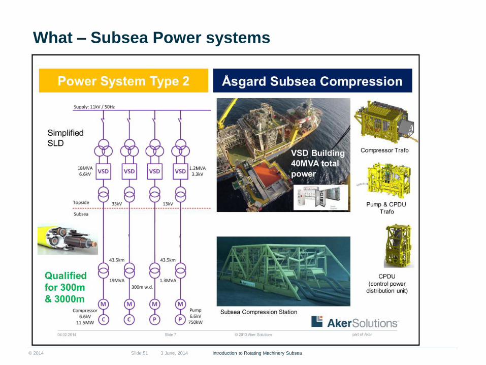
What – Subsea Power systems

© 2014 3 June, 2014 Introduction to Rotating Machinery Subsea Slide 52
What – Subsea Power systems

© 2014 3 June, 2014 Introduction to Rotating Machinery Subsea Slide 53
What – Subsea Power systems

© 2014
What – Subsea interfaces
■ Wet-mate connections for Power Systems ■ Allows connection of High-Voltage power by use of
ROV at depths down to 3000 m (10 000 ft)
■ Smaller connectors can be 3-phase
■ Larger connectors are 1-phase
■ Capacities: ■ Current: typ. from 100 A up to 1600 A
■ Voltage: typ. from 2 kV up to 30 kV
3 June, 2014 Introduction to Rotating Machinery Subsea Slide 54

© 2014
What – Subsea Transformer (example)
3 June, 2014 Introduction to Rotating Machinery Subsea Slide 55
© 2014
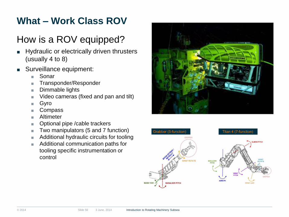
What – Work Class ROV
How is a ROV equipped? ■ Hydraulic or electrically driven thrusters
(usually 4 to 8)
■ Surveillance equipment: ■ Sonar
■ Transponder/Responder
■ Dimmable lights
■ Video cameras (fixed and pan and tilt)
■ Gyro
■ Compass
■ Altimeter
■ Optional pipe /cable trackers
■ Two manipulators (5 and 7 function)
■ Additional hydraulic circuits for tooling
■ Additional communication paths for
tooling specific instrumentation or
control
3 June, 2014 Introduction to Rotating Machinery Subsea Slide 56

© 2014
What – Work ROV tooling and interfaces
■ Examples: ■ Cleaning tools
■ Override tools
■ Torque tools (hydraulic)
■ Hot Stabs
3 June, 2014 Introduction to Rotating Machinery Subsea Slide 57

© 2014
Åsgard Subsea Compression
3 June, 2014 Introduction to Rotating Machinery Subsea Slide 58
© 2014
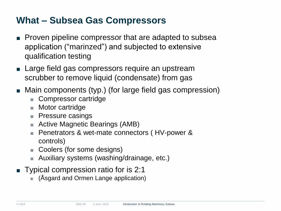
What – Subsea Gas Compressors
■ Proven pipeline compressor that are adapted to subsea
application (“marinzed”) and subjected to extensive
qualification testing
■ Large field gas compressors require an upstream
scrubber to remove liquid (condensate) from gas
■ Main components (typ.) (for large field gas compression) ■ Compressor cartridge
■ Motor cartridge
■ Pressure casings
■ Active Magnetic Bearings (AMB)
■ Penetrators & wet-mate connectors ( HV-power &
controls)
■ Coolers (for some designs)
■ Auxiliary systems (washing/drainage, etc.)
■ Typical compression ratio for is 2:1 ■ (Åsgard and Ormen Lange application)
3 June, 2014 Introduction to Rotating Machinery Subsea Slide 59
© 2014
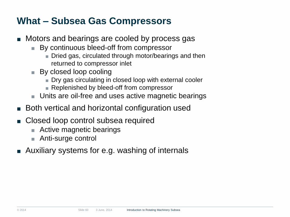
What – Subsea Gas Compressors
■ Motors and bearings are cooled by process gas ■ By continuous bleed-off from compressor
■ Dried gas, circulated through motor/bearings and then
returned to compressor inlet
■ By closed loop cooling ■ Dry gas circulating in closed loop with external cooler
■ Replenished by bleed-off from compressor
■ Units are oil-free and uses active magnetic bearings
■ Both vertical and horizontal configuration used
■ Closed loop control subsea required ■ Active magnetic bearings
■ Anti-surge control
■ Auxiliary systems for e.g. washing of internals
3 June, 2014 Introduction to Rotating Machinery Subsea Slide 60

© 2014
What - Subsea Compressors
3 June, 2014 Introduction to Rotating Machinery Subsea Slide 61

© 2014
What – Subsea Compression
Discharge
Cooler
TT PT TT PTFT
SC
Compressor
Pump
Inlet / Anti-
surge cooler
Scrubber
Well stream
Well stream
Liquid
Gas
Anti- surge ValveAnti- surge Cooler
Minimum
flow valve
Liquid
injection
line
Slide 62
Process Flow Diagram
3 June, 2014 Introduction to Rotating Machinery Subsea

© 2014
What – Subsea Compression
3 June, 2014 Introduction to Rotating Machinery Subsea Slide 63
Inlet & Antisurge
Cooler Separator Module
Compressor
Module
Train SCM

© 2014
■ Further development to: Reduce
system investment and operation cost
while increasing reliability, availability
and maintainability (RAM)
■ Investment ■ Reduced size/ weight (>50%)
■ No pump VSD or Barrier fluid HPU
■ No barrier fluid tubing
■ Reduced cable cost due to Low
frequency/ high voltage transmission
■ 30-40% cost reduction for a dual train
system
■ Operation ■ Reduced module retrieval weight
■ RAM ■ Simplified system functionality
■ No booster pump no level control,
no barrier fluid control
3-Jun-14 Slide 64
The potential…
Current design 12.5 MW train
Current design 6 MW train
Simplified design 6 MW train
3 June, 2014 Introduction to Rotating Machinery Subsea Slide 64
What – Compact Subsea Compression

© 2014
Subsea Industry Trends
■ Larger units (higher capacities and pressures)
■ Subsea power distribution
■ Simpler units / standardisation
■ Subsea factory
■ Longer step-outs – >100 miles ■ Enabling Arctic & subsea to beach developments
■ Barrier fluid less systems
■ Dual boost ■ Multiple in-well pumps + seabed pump
■ Low salinity & low sulphur sea water treatment
■ Ultra high pressure water injection with sea water treatment
■ Condition monitoring
■ All-electric actuators
3 June, 2014 Introduction to Rotating Machinery Subsea Slide 65

© 2014
Trends - Subsea Factory
3 June, 2014 Introduction to Rotating Machinery Subsea Slide 66
Subsea animation

© 2014 Slide 67
Drivers of future field developments
Deeper
waters,
complex
reservoirs,
harsh fluids
Drive for
increased oil
recovery from
existing fields
Longer subsea
step-outs
(distance from
well to process
facility)
Reduce costs to
drive marginal
developments
3 June, 2014 Introduction to Rotating Machinery Subsea

© 2014
REFERENCE INFORMATION & ACKNOWLEDEMENTS
■ Selected relevant papers ■ OTC 20078-PP Tyrihans Raw
Seawater Injection ■ OTC-21516-PP Development
and Testing of a Hybrid Boosting Pump
■ OTC 20030 Ormen Lange Subsea Compression Pilot – Subsea Compression Station
■ OTC 20146 BP King – Deep Multiphase Boosting made Possible
■ OTC 16447 An Efficient Wellstream Booster Solution for Deep and Ultra Deep Water Oil Fields
■ Subsea animation http://www.akersolutions.com/en/Global-menu/Media/vid-people/Our-products-and-services/Subsea-animation/
3 June, 2014 Introduction to Rotating Machinery Subsea Slide 68
■ Acknowledgement The authors would like to thank the following
colleagues within Aker Solutions for valuable
help and contributions in making this tutorial:
Åge Hofstad, Truls Normann, Kjell-Olav
Stinessen, Christian Høy, Odd Gilinsky, Steinar
Øyulvstad

© 2014
Copyright and disclaimer
Copyright Copyright of all published material including photographs, drawings and images in this document remains vested in Aker Solutions and
third party contributors as appropriate. Accordingly, neither the whole nor any part of this document shall be reproduced in any form nor
used in any manner without express prior permission and applicable acknowledgements. No trademark, copyright or other notice shall
be altered or removed from any reproduction.
Disclaimer This Presentation includes and is based, inter alia, on forward-looking information and statements that are subject to risks and
uncertainties that could cause actual results to differ. These statements and this Presentation are based on current expectations,
estimates and projections about global economic conditions, the economic conditions of the regions and industries that are major
markets for Aker Solutions ASA and Aker Solutions ASA’s (including subsidiaries and affiliates) lines of business. These expectations,
estimates and projections are generally identifiable by statements containing words such as “expects”, “believes”, “estimates” or similar
expressions. Important factors that could cause actual results to differ materially from those expectations include, among others,
economic and market conditions in the geographic areas and industries that are or will be major markets for Aker Solutions’ businesses,
oil prices, market acceptance of new products and services, changes in governmental regulations, interest rates, fluctuations in currency
exchange rates and such other factors as may be discussed from time to time in the Presentation. Although Aker Solutions ASA believes
that its expectations and the Presentation are based upon reasonable assumptions, it can give no assurance that those expectations will
be achieved or that the actual results will be as set out in the Presentation. Aker Solutions ASA is making no representation or warranty,
expressed or implied, as to the accuracy, reliability or completeness of the Presentation, and neither Aker Solutions ASA nor any of its
directors, officers or employees will have any liability to you or any other persons resulting from your use.
Aker Solutions consists of many legally independent entities, constituting their own separate identities. Aker Solutions is used as the
common brand or trade mark for most of these entities. In this presentation we may sometimes use “Aker Solutions”, “we” or “us” when
we refer to Aker Solutions companies in general or where no useful purpose is served by identifying any particular Aker Solutions
company.
Introduction to Rotating Machinery Subsea Slide 69 3 June, 2014

MICHAEL MANCUSO
INTRODUCTION TO SUBSEA

2
Michael Mancuso – Director of Technology, OneSubsea
Michael Mancuso is currently the Director of Technology for
OneSubsea. He leads the global R&D activities. Prior to his current role
and formation of OneSubsea, Michael served 13 years with
Cameron in several positions including Senior Engineer for several
subsea projects, Director of Marketing, management in finance
(mergers and acquisitions) and product management in both corporate
and the Valves & Measurement division. He holds a Bachelor of
Science in Mechanical Engineering from the University of Notre Dame
and a MBA from the C. T. Bauer School of Business at the University of
Houston.

3
Agenda
Defining Subsea
History
Importance of Deepwater Growth
Mega Project Execution Model
Subsea System Architecture
Remote Operations
Controlling the Infrastructure
Quality and Materials Requirements
Rotating Machinery Trends

4
OneSubsea Creation
Leading oilfield services
company
Leading provider of
subsea production systems
Leading provider of subsea
measurement, boosting and
process systems

5
OneSubsea Technologies and Services Offering
Field Development Planning
Petrotechnical Services
Production Assurance Consulting
Early Engineering Engagement
One-System Approach
Trees
Manifolds
Connection Systems
Wellheads
Multiphase Pumps
Single-Phase Pumps
Multiphase Compressors
Multiphase Meters and Wet Gas
Meters
Sampling
Separation
Tree and Manifold Controls
Multiphase Pump Controls
Multiphase Flow Controls
Topside and FPSO Controls
Diamould Electric Connectors
Swivel Stacks
Turrets
Submerged Loading Systems
Offshore Cryogenic Transfer
Installation and Commissioning
Life of Field
Asset Management
Integrated
Solutions
Production
Systems
Processing
Systems
Control
Systems
Swivel and
Marine
Systems
Services

6
What We Do
Not this.

7
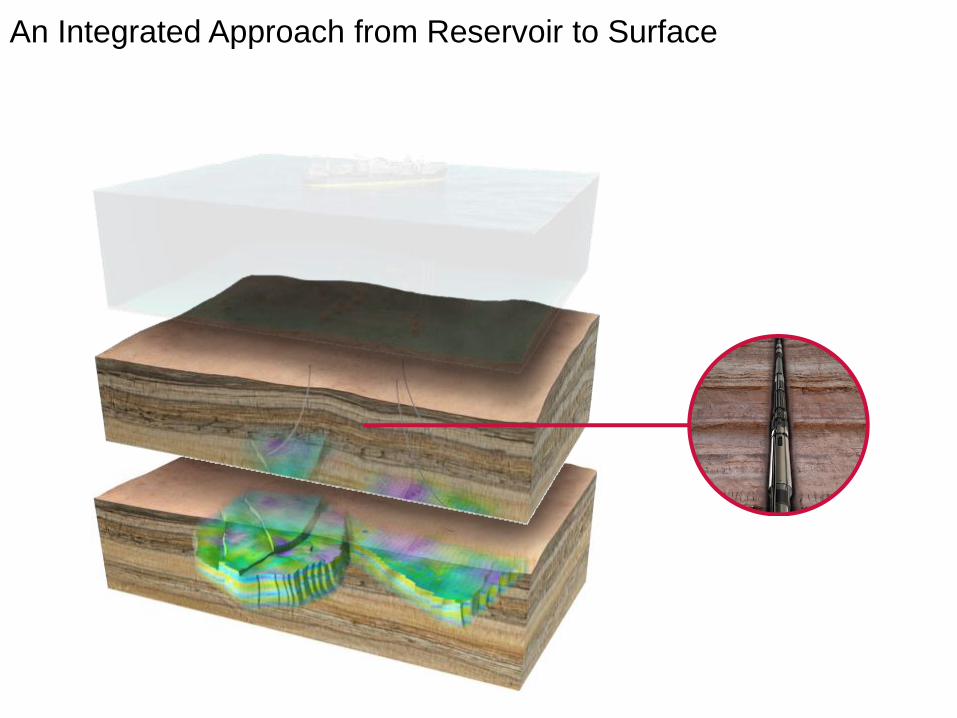
An Integrated Approach from Reservoir to Surface
8
An Integrated Approach from Reservoir to Surface

9
An Integrated Approach from Reservoir to Surface

10
What is Subsea?

11
Example Quad 204
• https://www.youtube.com/watch?v=-wB-xljllMs

12
Subsea Production System Overview
Paving the way in subsea innovation
1960s 1970s 1980s 1990s 2000s 2010s
1962
OneSubsea
designs and
builds the first
ever subsea
tree
1979 OneSubsea
installs first
electro-hydraulic
multiplex (E-H-
MUX) production
control system
OneSubsea Milestones
1983
OneSubsea
develops first
15,000 psi WP
subsea wellhead
1991
OneSubsea
introduces the
STM-15 marine
wellhead
2001
OneSubsea
installs world’s
first 15,000 WP
subsea tree and
production
manifold
2009
DC System, the
world’s first all-
electric (DC)
subsea
production tree,
comes online
2008 OneSubsea’s
MARS receives
Hart’s E&P
Meritorious
Award for
Engineering
Innovation
OneSubsea History
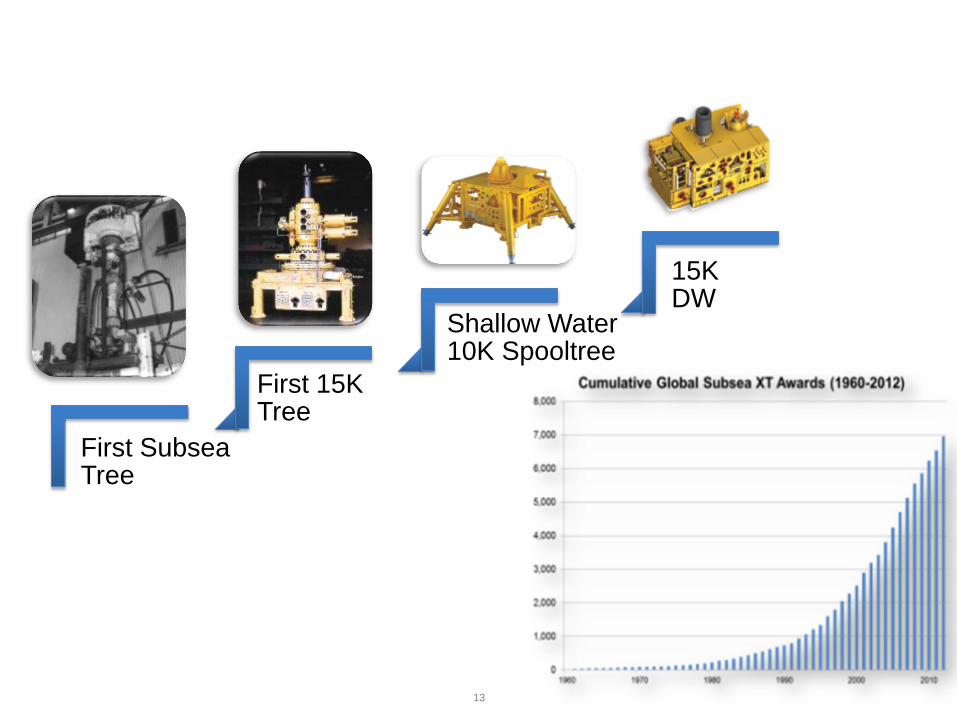
13
First Subsea Tree
First 15K Tree
Shallow Water 10K Spooltree
15K DW

14
Development Overview
FPSO BUOY
SHUTTLE TANKER
FLOWLINES
CONTROL UMBILICALS
DRILL CENTER

15
Components of a Subsea Production System
This diagram shows a typical drill
center (an arrangement of wells that
can be accessed from one mooring
pattern). Please note the following:
16
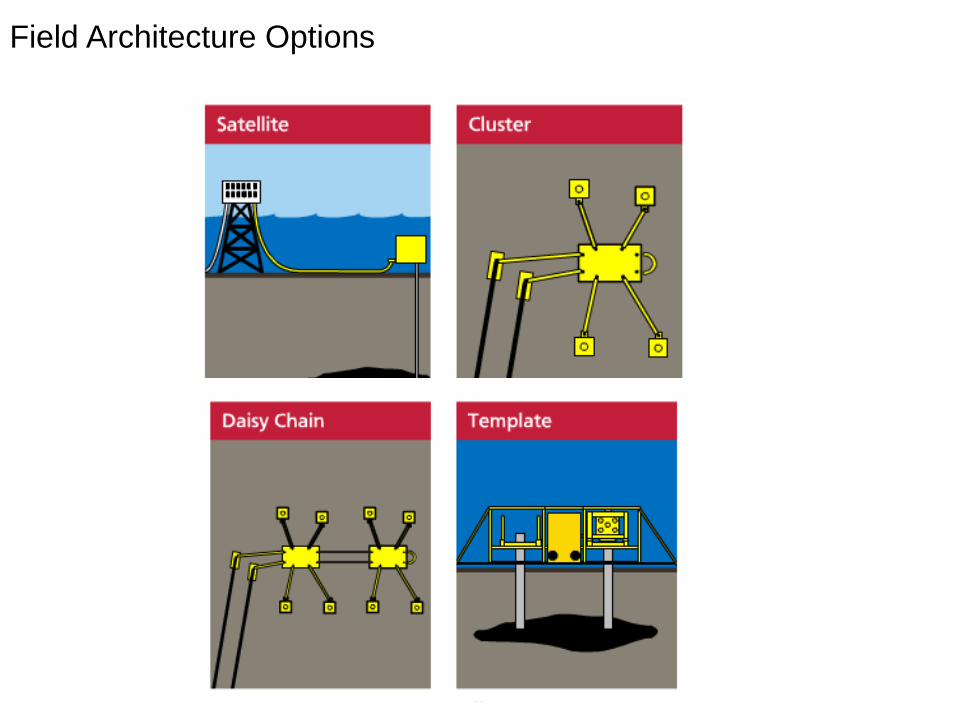
Field Architecture Options

17
Subsea Production System Overview

18
Tree Examples
19
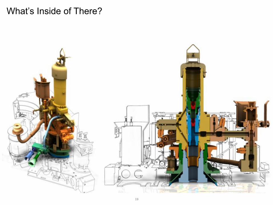
What’s Inside of There?
20
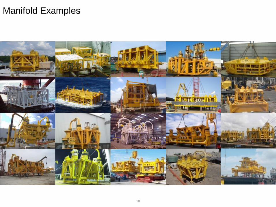
Manifold Examples
21
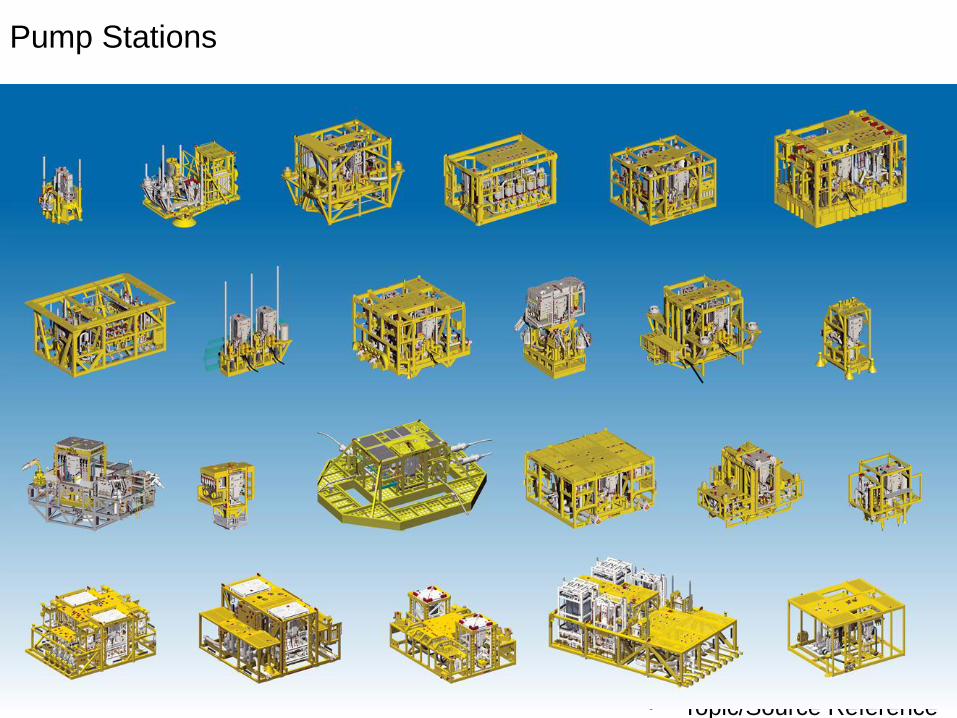
Pump Stations
• Topic/Source Reference
Goes Here

22
Controls
EPU MCS
HPU
SDU / SAM UTA
SCM
SCM
TUTU

23
System Integration Testing (SIT)

24
Trees: 40-90 tons
Manifolds: 100-500 tons
Jumpers: 50-200 feet
Umbilicals and Flowlines: Up to 100 km
How Big Is This Equipment?

25

26

27

28
• Installation videos
• Vertical monobore tree installation video
How Do These Get Installed Offshore?

29
• ROVs, accessibility studies

30

31
1-4 deg C
10,000 ft = <5000 psi
Dark
Can be muddy
Sealife
Geohazards – Mudslides, slope, gas domes
• Video of subsea life next to subsea tree
https://www.youtube.com/watch?v=Lt4fPT7Xdok
What Are The Conditions Down There?
32
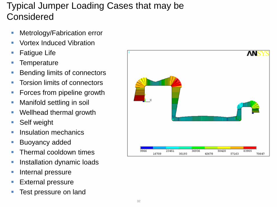
Metrology/Fabrication error
Vortex Induced Vibration
Fatigue Life
Temperature
Bending limits of connectors
Torsion limits of connectors
Forces from pipeline growth
Manifold settling in soil
Wellhead thermal growth
Self weight
Insulation mechanics
Buoyancy added
Thermal cooldown times
Installation dynamic loads
Internal pressure
External pressure
Test pressure on land
Typical Jumper Loading Cases that may be
Considered

33
Typical Subsea Project Timeline (PSVM)
2002-2004: Discoveries in Deepwater Angola
2005: Field Development Planning
2006-2007: FEED
2008: Award of Subsea EPC Contract to OneSubsea
2008-2010: Engineering and Procurement
2009-2012: Installation of Equipment and Facilities
2013: First Oil

34
Wells Taking Longer to Complete
• Rystad Energy 2014

35
Cost per day in deepwater rising

36
Forces Facing Operators (Our Customers)

37
Pre-Salt Challenging Scenario
• Pre-Salt – a New Scenario
Ultra-Deepwater Conditions – Risers
– Flow assurance
Logistics – 300 km from shore
– Lack of infrastructure
Fluids with Contaminants

38

39

40
Major Play – Lower Tertiary
High Shut-In Pressures (>15K)
Low Permeability
Long Tiebacks
Long-Term Dedication to Developing GoM (Many Long-Term Contracted Floaters)

41
Overall Longstanding Themes
AVAILABILITY….. (Including Reliability)
More Than 25 years of Life
Maximize Recovery
Environmental
Tooling and Life-of-Field Support Teams
Redevelopment of Maturing Fields
Intervention Costs are HIGH
Size and Complexity Increases

42
The Future

43
Separation? Reinjection? Storage?

44
Compression Technology
Developed in Phases Build the Offering
Become a Leader in
Integration
Create the “Subsea Factory”
5MW and Above
Ability to Handle Wet Gas
ONESUBSEA