ct74 user's guide - lathem
TRANSCRIPT

CT SeriesTerminal User’s Guide
Model CT74

THIS EQUIPMENT COMPLIES WITH FCC REQUIREMENTS PURSUANT OF PART-15
This device complies with Part 15 of the FCC Rules. Operation is subject to the following two conditions: (1) this device may not cause harmful interference, and (2) this device must accept any interference received, including interference that may cause undesired operation. WARNING: Changes or modifications to this product not expressly approved by the party responsible for compliance could void the user’s authority to operate this equipment.
Lathem Time
210 The BluffsMableton, GA 30126
www.lathem.com
Copyright © 2018 Lathem Time Corporation. All rights reserved.
Revised 11-26-2018
Document number: USG0104A

Contents • iii
Contents
Package Contents 1
Install the CT74 Clock 2
PayClock Online 4
Using the CT74 Clock 6
Supervisor Transactions 10
Enrolling Faces 13
Administrator Functions 15
Troubleshooting the CT74 20
Appendix A – Enrollment Guide 22
Appendix B – Testing the Connection to PCO 24
Appendix C – Using the Select Transaction Screen in Auto-Punch Mode 26
Appendix D – Bell Relay Connections 27
Appendix E – Access Relay Connections 32
Appendix F – Add/Edit/Delete Bell Events 34


Package Contents • 1
Package Contents
Please verify that your package includes the following items. If your package is missing an item, please call our help desk at (800) 224-1877.
Note: Remove the protective film on the clock bezel and touch screen by pulling the tab in the upper right corner after the clock is installed.
Recommended Installation Tools
Online and Email Support
Lathem.com provides access to numerous support resources. Visit the following link: http://kb.lathem.com for additional help or to submit a question. You should receive a reply within 24 hours.
Telephone Support
The help desk is available between the hours of 8am and 6pm ET Monday through Friday. Please call (404) 691-0400 to speak with our help desk.

2 • Install the CT74 Clock
Install the CT74 Clock
Step 1: Select a site to install your clock that will be convenient to employees clocking in and out. When deciding where the clock will be installed, keep in mind that an 115vAC power outlet should be within reach of the mounting location as well as a wired internet connection. Note about Direct Sunlight – It is not recommended to have the clock mounted in a location where it is exposed to direct sunlight. This could be troublesome during the registration process.
Step 2: After selecting the appropriate installation site, use the clock to determine the appropriate height. Have the shortest employee stand in front of the clock. Hold the clock on the wall so that this employee can comfortably center their face in the LCD display window. Mark the height of the clock on the wall. Note: Taller employees can easily adjust their stance to center their face in the LCD display window.
Install the mounting-plate to the wall using the supplied screws. For sheetrock walls, drill a 3/16” diameter hole through each of the four screw locations; each approx. 1-1/2” deep. Install the plastic “anchors” included in the mounting screw packet.

Install the CT74 Clock • 3
Step 3: The CT74 clock communicates with PayClock Online using a Wired Network Connection. Plug the wired network cable into the Ethernet port and the Power Adapter plug into the power adapter port located in the compartment on the back of the clock.
Step 4: Align the CT clock with the tabs on the mounting-plate and secure the two together with the 2 Philips head screws. Be careful not to pinch the AC cord or network cable.
When finished, plug the power adapter into an AC wall outlet.

4 • PayClock Online
PayClock Online
The PayClock Online product communicates with the clock over the internet.
Adding a CT74 clock Adding a CT74 clock to PayClock Online is a 2 step process. Add the clock in PayClock Online first and then from the clock connect to PayClock Online over the internet.
Step 1 - Adding a CT74 Clock
The CT series clock must be added to PayClock Online first otherwise the connection will fail.
• Log into PayClock Online and select Clocks > Manage Clocks from the list of items on the left.
• Click New. The Select Clock Type window will open.
• Choose CT74 and click Select.
• The clock properties will display.
• From the General tab, enter a name for the clock under Device Nickname.
• Next enter the serial number of the clock. Note: Enter the serial number exactly as it shows on the label on the clock.
• Click Save.
Step 2 - Connect the Clock to PayClock Online
The clock must be set up in PayClock Online before attempting this step. The clock must be powered up and connected to the network with access to the internet.
• At the clock tap the Settings button. Enter the administrator PIN and press OK.
• From the Administrator Menu tap Sync Now.

PayClock Online • 5
• The clock will connect over the internet to PayClock Online.
• After the connection is made the data will be downloaded to the clock and it will be ready for use.
• When complete a cloud icon will show on the clock’s display identifying it is connected to PayClock Online.
• The clock will be operational and ready for use.

6 • Using the CT74 Clock
Using the CT74 Clock
The clock will be ready to use after downloading the employees. To punch, the employee will simply present an enrolled face, badge or use a PIN. They will be identified and punched In or Out.
When the transaction is successful; a confirmation beep will sound, a text message will appear, a custom audio message may be played, and the display will turn either green or red indicating a good or bad transaction.
Auto-Punch Mode Enabled By default, the clock is set to automatically record a punch for the employee and not display the Select Transaction screen.
Employee Transactions
Employees can record transactions or view total information by presenting their face, a badge or entering a PIN.
Clocking IN/Out – Facial Recognition
• Present an enrolled face at the clock.
• When the face is verified a confirmation will sound/display.
Clocking IN/Out - Badge
• Move the badge over the badge reader symbol on the front of the clock.
• When the badge is read a confirmation will sound/display.
Clocking IN/Out - PIN
• Tap the PIN Entry button on the touch-pad of the clock.
• The IDENTIFICATION screen will display. Using the numeric key pad enter the employee’s PIN number and tap OK.
• A confirmation will sound/display.

Using the CT74 Clock • 7
Department Transfers
• Present face, the clock will start scanning.
• Tap the Stop Scan button, the clock will go to the PIN entry screen.
• Tap the Scan Face button, the clock will validate the face.
• At the Select Transaction screen tap the Transfer button.
• Tap the desired department from the list. A confirmation screen will display showing the department into which the employee transferred.
Amount Entries
• Present face, the clock will start scanning.
• Tap the Stop Scan button, the clock will go to the PIN entry screen.
• Tap the Scan Face button, the clock will validate the face.
• At the Select Transaction screen tap the Amounts button.
• Using the numeric key pad enter the value for the amount at the AMOUNT ENTRY screen.
• Tap OK, a confirmation screen will display showing the amount entered for the employee.
Viewing Totals
• Present face, the clock will start scanning.
• Tap the Stop Scan button, the clock will go to the PIN entry screen.
• Tap the Scan Face button, the clock will validate the face.
• At the Select Transaction screen tap the Totals button.
• A confirmation will sound and the employee’s grand totals for the pay period and any benefit time will display.

8 • Using the CT74 Clock
Auto-Punch Mode Disabled When the Auto-Punch Mode is disabled the Select Transaction screen will display with every input method. Note: The Select Transaction screen is on a 2 second timer. If a selection isn’t made within that time a normal In/Out punch will be recorded.
Employee Transactions
Employees can record transactions or view total information by presenting their face, a badge or entering a PIN.
Clocking IN/Out – Facial Recognition
• Present an enrolled face at the clock.
• When the face is verified a confirmation will sound and the Select Transaction screen will display.
• Tap a button to select your transaction or wait for the 2 second timer to elapse and a punch will be recorded.
• A confirmation will sound/display.
Clocking IN/Out - Badge
• Move the badge over the badge reader symbol on the front of the clock.
• When the badge is read a confirmation will sound and the Select Transaction screen will display.
• Tap a button to select your transaction or wait for the 2 second timer to elapse and a punch will be recorded.
• A confirmation will sound/display.
Clocking IN/Out - PIN
• Tap the PIN Entry button on the touch-pad of the clock.
• The IDENTIFICATION screen will display. Using the numeric key pad enter the employee’s PIN number and tap OK.

Using the CT74 Clock • 9
• The Select Transaction screen will display.
• Tap a button to select your transaction or wait for the 2 second timer to elapse and a punch will be recorded.
• A confirmation will sound/display.
Department Transfers
• Present an enrolled face in front of the clock
• At the Select Transaction screen tap the Transfer button.
• Tap the desired department from the list. A confirmation screen will display showing the department into which the employee transferred.
Amount Entries
• Present an enrolled face in front of the clock
• At the Select Transaction screen tap the Amounts button.
• Using the numeric key pad enter the value for the amount at the AMOUNT ENTRY screen.
• Tap OK, a confirmation screen will display showing the amount entered for the employee.
Viewing Totals
• Present an enrolled face in front of the clock
• At the Select Transaction screen tap the Totals button.
• A confirmation will sound and the employee’s grand totals for the pay period and any benefit time will display.

10 • Supervisor Transactions
Supervisor Transactions
Supervisors have the ability at the clock to view and edit employee punches, add new employees, send messages and override shift lockouts.
To set up an employee as a supervisor, in PayClock Online select the desired employee and set the employee’s Access Profile to “Supervisor”, then select the employees they will be able to manage.
To enter into supervisor mode at the clock tap the SUPERVISOR button. The IDENTIFICATION screen will display. Use one of the following methods to enter Supervisor Mode:
• Tap Scan Face and present an enrolled face in front of the clock.
• Using the numeric key pad enter the supervisors PIN and tap OK.
• Move the supervisors badge over the badge reader symbol on the front of the clock.
Viewing Punches
At the clock tap the SUPERVISOR button. The IDENTIFICATION screen will display.
• Using either a face, badge or PIN enter supervisor mode.
• At the Employee selection screen, tap on the name of the desired employee.
• Tap Punches. The Punches screen will display.
• Use the left, right, up or down arrows to scroll through the punch information.
• When finished tap to return to the default screen.
Supervisor Transactions • 11
Adding Punches
Tap the SUPERVISOR button on the clock. The IDENTIFICATION screen will display.
• Using either a face, badge or PIN enter supervisor mode.
• At the Employee selection screen, tap on the name of the desired employee.
• Tap Punches. The Punches screen will display.
• Use the left or right arrows to select the desired date and press the +ADD button.
• Using the up and down arrows set the desired hour and minute and then tap ADD.
• At the confirmation screen select Yes to add the punch. The added punch will display on the screen and will be added to the employee’s timecard.
• When finished tap to return to the default screen.
Viewing Totals
Tap the SUPERVISOR button on the clock. The IDENTIFICATION screen will display.
• Using either a face, badge or PIN enter supervisor mode.
• At the Employee selection screen, tap on the name of the desired employee.
• Tap Totals. The employee’s grand totals for the pay period and any benefit time will display.
• When finished tap to return to the default screen.
Send Message
Tap the SUPERVISOR button on the clock. The IDENTIFICATION screen will display.
• Using either a face, badge or PIN enter supervisor mode.
• At the Employee selection screen, tap on the name of the desired employee.
12 • Supervisor Transactions
• Tap Messaging. Select to send a sound message or a text message.
• Using the left and right arrows select the desired sound or text message.
• At the confirmation screen select Yes. On the next punch the employee will receive the sound or text message.
• When finished tap to return to the default screen.
Override Lockout
Tap the SUPERVISOR button on the clock. The IDENTIFICATION screen will display.
• Using either a face, badge or PIN enter supervisor mode.
• At the Employee selection screen, tap on the name of the desired employee.
• Tap Override Lockout.
• At the confirmation screen select Yes to have the next punch for the employee ignore the shift lockout.
• When finished tap to return to the default screen.

Enrolling Faces • 13
Enrolling Faces
The CT74 model utilizes an “embedded facial recognition” system. This means that employees will punch in and out by presenting their face in front of the clock’s cameras. The clock verifies the face image and records the punch. Employees can punch and review time balances by presenting their face.
The Admin or Supervisor have the ability to enroll employee faces.
To enroll a face, tap the ENROLL button and enter the Admin PIN then tap OK.
Face Enrollment Guidelines
• The CT74 clock is for use indoors; do not position the clock in direct sunlight.
• Use normal facial expressions and avoid wearing sunglasses.
• If glasses or a hat is worn, please take the glasses and/or hat off halfway through the enrollment process for better face recognition.
• Hair Style – If the employee has a hair style that has their hair covering or blocking their eyes, move the hair away from the during the registration process.
• Bend into the camera, keeping the distance between the face and screen at 9 to 25 inches for best results.
• Keep the face centered between the 2 cameras.
• The blue lined frame displays when the employees face is successfully being detected.
Sync to All Clocks
There is an enrollment option that allows you to send the face enrollment to all clocks or to keep it “locked” to a specific clock. This is used if you have multiple clocks and the employees face isn’t consistently read from all clocks. You can have enrollments that are specific to the clock if needed.

14 • Enrolling Faces
Enrolling Employee Faces
At the clock tap the ENROLL button and enter the Admin PIN then tap OK.
• The Employee selection screen will display.
• With the employee standing so their face is in the middle of the 2 cameras with 9 to 25 inches between the face and the clock, tap on their name.
• The image collecting screen will display, start the face recognition enrollment.
• Perform small head circles to the right and then small head circles to the left.
• Move the face closer to the clock and then move the face back.
• Turn the head to the right and then to the left.
• Raise the head up slightly and then lower the head down slightly.
• Continue moving face as described above.
• The progress bar at the bottom of screen will display the process of the imaging.
• When the face is enrolled the clock will display, “Face Scan Saved”.
• Uncheck the “Sync to All Clocks” option if you want the employees face enrollment kept on this clock and not sent to other clocks in your PayClock Online system.
• Choose to enroll another employee or if you are finished with enrollments choose Enrollment Complete.
• The clock is ready to starting accepting punches for the enrolled employees.
Note: See Appendix A for additional details in the Enrollment Guide.
Administrator Functions • 15
Administrator Functions
The CT clock has one administrator. The Settings function allows you to review the device information, set up the network communications, set the time / date, review an error log and reset the clock to the factory defaults.
To enter the settings mode, at the clock tap the Settings button. The IDENTIFICATION screen will display.
• Using the numeric key pad enter the administrator PIN number and tap OK.
• The Administrator Menu screen will display.
Network
This menu allows you to configure the network communication settings between the clock and PayClock Online.
At the clock tap the Settings button and enter the administrator PIN.
• The Administrator Menu screen will display.
• Tap Network. The Network Setup screen will display.
• If you want to set the clock’s IP address as a “Static” IP turn off DHCP by tapping the button. The screen will refresh and the fields will become active.
• Tap IP Address. The IP Address screen will display.
• Using the numeric key pad enter the IP address you want to assign to the clock and tap OK.
• Do the same for the Subnet Mask and Gateway.
• When finished tap to return to the default screen.

16 • Administrator Functions
Sync Now
This menu allows you to initiate a manual synchronization between PayClock Online and the clock.
At the clock tap the Settings button and enter the administrator PIN.
• The Administrator Menu screen will display.
• Tap Sync Now, the clock will start the update process and return the default screen when finished.
Date/Time Setup
This menu allows you to manually configure the time zone, DST and how the hours will display on the clock.
At the clock tap the Settings button and enter the administrator PIN.
• The Administrator Menu screen will display.
• Tap Date & Time and make the desired changes.
• When finished tap to return to the default screen.
Signal-Door Access
This menu allows you to configure how the clock uses the on-board relay.
At the clock tap the Settings button and enter the administrator PIN.
• The Administrator Menu screen will display.
• Tap Signal-Door Access. The signal-door access screen will display.
• Select the Relay Mode. o Off – The relay is disabled. o Access – The relay will be used to activate a door strike
allowing employees to enter the facility. o Signal – The relay will open/close to sound the signaling
device.
• The Schedule button will display if Signal is selected. Press Schedule and enter the bell events. Up to 100 events can be programmed.
• Select the duration to for the relay. By default, it is set at 5 seconds.
Administrator Functions • 17
• Use the Test button to activate the on-board relay to test the connection.
• When finished tap to return to the default screen.
See Appendix E for steps to add/edit/delete bell events.
Device Info
This menu item displays clock information such as the clocks serial number and software version.
At the clock tap the Settings button and enter the administrator PIN.
• The Administrator Menu screen will display.
• Tap Device Info. The device information will display.
• When finished tap to return to the default screen.
Support
This menu item allows you to test the clocks connection to the internet and PayClock Online. You can also display any errors that the clock may have experienced.
Testing the Clocks Internet Connection
At the clock tap the Settings button and enter the administrator PIN.
• The Administrator Menu screen will display.
• Tap Support and then Test Connection.
• The internet connection, ports and connection to PayClock Online will be tested.
• When finished tap to return to the default screen.
See Appendix B for details on testing the clocks connection.
Reviewing the Clocks Error Log
At the clock tap the Settings button and enter the administrator PIN.
• The Administrator Menu screen will display.
• Tap Support and then Error Log.
• Any logged information will display.

18 • Administrator Functions
• When finished tap to return to the default screen.
Check for Updates
This menu item allows the clock to check to see if any updates are available. If updates are found the clock will guide the user through the update process.
At the clock tap the Settings button and enter the administrator PIN.
• The Administrator Menu screen will display.
• Tap Check for Updates. Please be patient this may take a few minutes. Follow the on-screen instructions.
• When finished tap to return to the default screen.
Factory Reset
Use caution when selecting this menu item. This menu item will reset the entire clock to the manufacturer default settings.
All settings, administrators, supervisors, employees and data will be cleared from the clock; you cannot recover this information.
At the clock tap the Settings button and enter the administrator PIN.
• The Administrator Menu screen will display.
• Tap Factory Reset. The warning screen will display.
• Tap Reset Device if you are sure you wish to reset and clear the clock.
• The clock will reboot and restart as if it were a new clock that had never been used.
Auto-Punch Mode
By default, the clock is set to automatically record a punch for the employee and not display the Select Transaction screen. To have the Select Transaction screen display by default uncheck this option.
To change this setting; at the clock tap the Settings button and enter the administrator PIN.
• The Administrator Menu screen will display.

Administrator Functions • 19
• Change the option by tapping Auto-Punch Mode. Note: A check in the box means the option is selected.
• When finished tap to return to the default screen.
Note: The Select Transaction screen can still be accessed by an employee if needed. See Appendix C for details on how to access the Select Transaction screen with the clock in Auto-Punch Mode.

20 • Troubleshooting the CT74
Troubleshooting the CT74
If the clock doesn’t communicate with PayClock Online, try these suggestions:
General Troubleshooting • Make sure that all connections are secure and the cable is intact.
• Make sure that the network cable is securely connected to the Ethernet port on the clock.
• Make sure that the clock’s power supply is securely connected to an electrical outlet.
• Make sure that the power supply is securely connected to the clock and the unit is powered up.
If after going through each item above you are still not communicating, have the network administrator or IT person make sure there aren’t any issues with the network.
CT74 Troubleshooting
Issue Resolution
The clock isn’t connecting to PayClock Online.
If your clock isn’t connecting to PayClock Online, use the Test Connection button. See Appendix B for details.
What does the cloud on the display represent?
This represents that the clock is connected to PayClock Online.
Why can’t I open the Enroll screen on a CT74? I tap Enroll and get a sound but the screen doesn’t open?
The clock lost the connection to the internet. The clock must have an active internet connection.

Troubleshooting the CT74 • 21
Why does the clock show “Punch Accepted” instead of Punch In or Out when an employee punches?
The clock lost the connection to the internet. The clock must have a connection to the internet to determine if a punch is In or Out. Check to see if the cloud icon is displaying at the top of the screen.
Do I need to routinely clean the camera lens on the CT74 clock?
Dust may settle on the front of the clock so the front of the clock may need cleaning from time to time. To clean, gently wipe the front of the clock it with a soft cloth (not paper). Avoid using water or cleaners.
Why is the CT74 not reading the employee’s face when enrolling or punching?
-If the employee’s facial appearance has changed, re-enroll the employee.
-Make sure the employee is presenting their face within range of the clock, within 9 to 25 inches.
No matter how the employee presents their face, it will not recognize the employee.
Try re-enrolling the employee’s face.
The employee’s facial appearance has changed and the clock will not recognize their face.
Try re-enrolling the employee’s face.
Is the CT74 waterproof? NO, make sure to keep the clock away from water or a wet/damp environment.
What does the blinking light on the front of the clock mean?
This blinking light represents the connection to the wired network (LAN).

22 • Appendix A – Enrollment Guide
Appendix A – Enrollment Guide
Follow these guidelines for trouble-free enrollments.
During the enrollment process the employee should keep their eyes centered on the screen at all times. Try to keep a solid blue box around your face by following the steps below.
Position yourself and bend at the waist to bring your face 1 - 2.5 ft. from the screen on the clock.
The line of dots at the bottom of the screen indicate how much data is needed to complete the enrollment.
The clock is preparing to locate points. Identification images will only be taken when the blue box appears around your face.
Slowly make an imaginary circle with your nose. Two small circles to the right and two to the left while keeping your eyes centered on the screen.
Appendix A – Enrollment Guide • 23
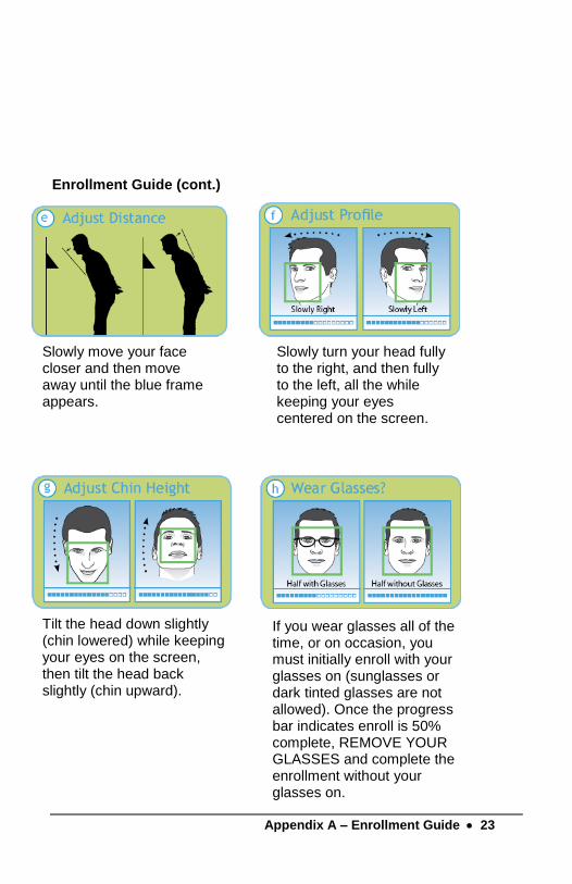
Enrollment Guide (cont.)
Slowly move your face closer and then move away until the blue frame appears.
Slowly turn your head fully to the right, and then fully to the left, all the while keeping your eyes centered on the screen.
Tilt the head down slightly (chin lowered) while keeping your eyes on the screen, then tilt the head back slightly (chin upward).
If you wear glasses all of the time, or on occasion, you must initially enroll with your glasses on (sunglasses or dark tinted glasses are not allowed). Once the progress bar indicates enroll is 50% complete, REMOVE YOUR GLASSES and complete the enrollment without your glasses on.

24 • Appendix B – Testing the Connection to PCO
Appendix B – Testing the Connection to PCO
Important This tool has been designed to assist you in the event the clock fails to connect to PayClock Online(PCO). Even with this tool it may be necessary to involve your IT department or someone familiar with your network if you have connection issues.
The CT series clock has a function that will allow the user to test the connection to PayClock Online. This test will verify the internet connection, access to the internet through the required ports and the connection to the PayClock Online service.
With the clock powered up and connected to the network, tap the Settings button and enter the administrator PIN.
• The Administrator Menu screen will display.
• Tap Support and then Test Connection.
Test 1 - Internet connection test.
Pass = The test cycle will move to the port test.
Fail – What should I do if this test fails?
• Does another device successfully connect to the internet? Such as a laptop.
• Does the clock show an IP address?
➢ Go to Settings>Network
• If no IP Address shows contact your IT department for assistance.

Appendix B – Testing the Connection to PCO • 25
Test 2 – Ports used by the clock will tested.
Pass = The test cycle will move to the PayClock Online service test.
Fail – What should I do if this test fails?
• Open the listed port(s) to traffic.
• Contact your IT department to open the listed port(s) to traffic.
Test 3 – PayClock Online Service used by the clock will tested.
Pass = The test cycle will display a summary of the test.
Fail – What should I do if this test fails?
• Open the listed port(s) to Inbound / Outbound traffic.
• Contact your IT department to open the listed port(s) to traffic.
Notes
The internet test will attempt to ping www.google.com. If ping is disabled on the network a false test result could be displayed and may require you to involve your IT department or someone familiar with your network.
It may be necessary to involve your IT department or someone familiar with your network if there is a failure with the Ports or PayClock Online Services test which requires changes to the network / firewall settings.
26 • Appendix C – Using the Select Transaction Screen in Auto-Punch Mode
Appendix C – Using the Select Transaction Screen in Auto-Punch Mode
By default, the CT74 is set to automatically record a punch for the employee and not display the Select Transaction screen. The Select Transaction screen allows the employee to perform department transfers, enter amounts or check their worked/non-work balance. The Select Transaction screen can still be accessed by an employee if needed by following these steps.
• Present face, the clock will start scanning.
• Tap the Stop Scan button, the clock will go to the PIN entry screen.
• Tap the Scan Face button, the clock will validate the face.
• Upon a successful validation the clock will display the Select Transaction screen.
• The employee should tap the desired function button.
OR
• Present face, the clock will start scanning.
• Tap the Stop Scan button, the clock will go to the PIN entry screen.
• Enter the PIN and tap OK. Note: PIN entry must be enabled on the clock and the employee.
• The clock will display the Select Transaction screen.
• The employee should tap the desired function button.

Appendix D – Bell Relay Connections • 27
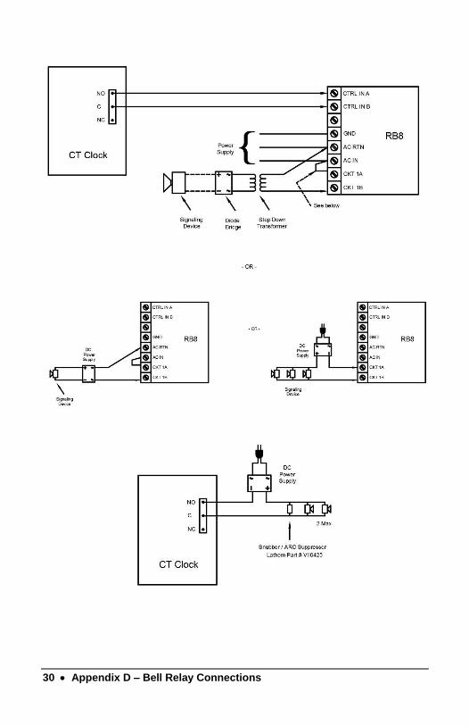
Appendix D – Bell Relay Connections
The CT series clock has a built-in relay that can control bells or door access.
Relay Specifications
• Type: Dry Contact Closure
• Rating: 2 amps at 24VDC or 120VAC
• Contacts: NO-Normally Open, COM-Common, NC-Normally Closed
Bell Relay Connections
When you are connecting to a signaling device make sure you have the following skills:
• Understand basic wiring principles and techniques
• Can interpret wiring diagrams
• Have circuit wiring experience
Note: The wiring must be installed in accordance with national and local electrical codes.
To connect the signaling device
• Unplug the relay screw terminal connector on the back of the clock.

28 • Appendix D – Bell Relay Connections
• Connect the wires from the signaling device to the screw terminals. Plug the terminal connector into the socket on the clock. Only one (1) wire should be inserted into the terminal block positions NO and COM, all wire splices should be done externally. See the following diagrams for details.
Important! Relay contacts provide no power for signaling devices. The relay is a dry contact closure rated 2 amps at 24VDC or 120 VAC. Connecting a device or series of devices that draw more than the rated amperage from the terminal will result in serious damage! It is recommended to use the optional RB8 Relay Booster Box to control devices that require more than 2 amps.

Appendix D – Bell Relay Connections • 29
30 • Appendix D – Bell Relay Connections

Appendix D – Bell Relay Connections • 31
Wiring to P.A. System / Tone Generator
Important! Connecting the CT clock to a public address (PA) system requires the use of an external Tone Generator. Contact your PA supplier to acquire an appropriate Tone Generator for your system.

32 • Appendix E – Access Relay Connections
Appendix E – Access Relay Connections
When you are connecting to a door access device make sure you have the following skills:
• Understand basic wiring principles and techniques
• Can interpret wiring diagrams
• Have circuit wiring experience
Note: The wiring must be installed in accordance with national and local electrical codes.
Connecting the CT clock to a Door Strike
• Unplug the relay screw terminal connector on the back of the clock.
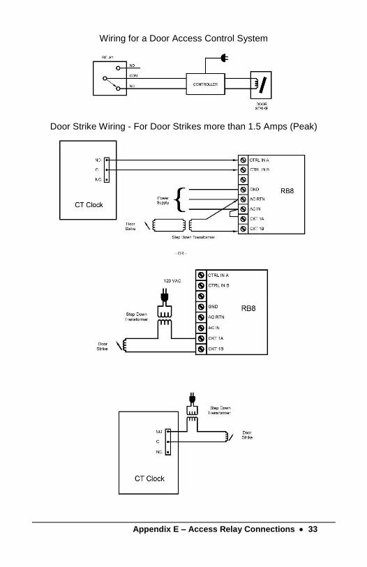
• Connect the wires from the door access device to the screw terminals. Plug the terminal connector into the socket on the CT clock. Only one (1) wire should be inserted into the terminal block positions NO and COM, all wire splices should be done externally. See the following diagrams for details.
Important! Relay contacts provide no power for signaling devices. The relay is a dry contact closure rated 2 amps at 24VDC or 120 VAC. Connecting a device or series of devices that draw more than the rated amperage from the terminal will result in serious damage! It is recommended to use the optional RB8 Relay Booster Box to control devices that require more than 2 amps.
Appendix E – Access Relay Connections • 33
Wiring for a Door Access Control System
Door Strike Wiring - For Door Strikes more than 1.5 Amps (Peak)

34 • Appendix F – Add/Edit/Delete Bell Events
Appendix F – Add/Edit/Delete Bell Events
Up to 100 events can be programmed. Events consist of the time and the day of week the event will activate the relay.
Adding a Bell Event
• From the CT tap Settings and enter the administrator PIN and tap OK.
• From the Administrator Main Menu tap Signal-Door Access.
• The Signal-Door Access screen will display.
• Tap Signal under the Relay Mode.
• Tap Schedule under Signal Events. The Signal Event Schedule screen will display.
• Tap “add event”. The Add Event screen will display.
• Using the up and down arrow keys select the desired hour, minute and AM/PM for the bell event.
• Tap on the desired days of the week, a check will display in the box identifying the day is selected.
• Tap OK to save the event. The programmed event will display in the list.
• Continue adding the desired events.
• When finished tap to return to the default screen.
Editing a Bell Event
• From the CT tap Settings and enter the administrator PIN and tap OK.
• From the Administrator Main Menu tap Signal-Door Access.
• The Signal-Door Access screen will display.

• 35
• Tap Signal under the Relay Mode.
• Tap Schedule under Signal Events. The Signal Event Schedule screen will display with all the schedule events.
• Tap on the desired event and make the needed changes.
• Tap OK to save the changes.
• When finished tap to return to the default screen.
Deleting a Bell Event
• From the CT tap Settings and enter the administrator PIN and tap OK.
• From the Administrator Main Menu tap Signal-Door Access.
• The Signal-Door Access screen will display.
• Tap Signal under the Relay Mode.
• Tap Schedule under Signal Events. The Signal Event Schedule screen will display with all the schedule events.
• Tap Delete and then Yes to remove the event.
• When finished tap to return to the default screen.

One-Year Limited Warranty
Lathem warrants the hardware products described in this guide against defects in material and workmanship for a period of one year from date of original purchase from Lathem or from an authorized Lathem reseller. The conditions of this warranty and the extent of the responsibility of Lathem Time Corporation (“Lathem”) under this warranty are listed below.
1. This warranty will become void when service performed by anyone other than an approved Lathem warranty service dealer results in damage to the product.
2. This warranty does not apply to any product which has been subject to abuse, neglect, or accident, or which has had the serial number altered or removed, or which has been connected, installed, adjusted, or repaired other than in accordance with instructions furnished by Lathem.
3. This warranty does not cover dealer labor cost for removing and reinstalling the machine for repair, or any expendable parts that are readily replaced due to normal use.
4. The sole responsibility of Lathem under this warranty shall be limited to repair of this product, or replacement thereof, at the sole discretion of Lathem.
5. If it becomes necessary to send the product or any defective part to Lathem or any authorized service dealer, the product must be shipped in its original carton or equivalent, fully insured with shipping charges prepaid. Lathem will not assume any responsibility for any loss or damage incurred in shipping.
6. WARRANTY DISCLAIMER AND LIMITATION OF LIABILITY: Except only the limited express warranty set forth above, the products are sold with no expressed or implied warranties of any kind, and the implied warranties of merchantability and fitness for a particular purpose are hereby expressly disclaimed. No warranties are given with respect to products purchased other than from Lathem or an authorized Lathem reseller and any such products are purchased "as is, with all faults." In no event will Lathem be liable for any direct, indirect, special, incidental or consequential damages arising out of or in connection with the delivery, use or inability to use, or performance of this product. In the event any limited remedy given herein shall be deemed to have failed of its essential purpose, Lathem's maximum liability shall be to refund the purchase price upon return of the product.
7. Proof of date of purchase from Lathem or an authorized Lathem reseller is required for warranty service on this product.
8. This Warranty grants specific legal rights. Additional legal rights, which may vary by locale, may also apply.
9. Should any difficulties arise with the performance of this product during warranty, or with any Lathem authorized service centers, contact Lathem Time.


USG0104