installation & user's guide - lathem · ddc-tc wiring ... slide the lens and circuit board...
TRANSCRIPT
Digital Display Wall Clock
DDC2 / DDC4 Series
Installation &
User's Guide

OMNI:CHRON, mini:master, Lathem and the Lathem logo are registered trademarks of Lathem Time
Corporation. Other product names mentioned in this manual may be trademarks of their respective
companies and are hereby acknowledged.
WARNING: Changes or modifications to this product not expressly approved by the party responsible for
compliance could void the user’s authority to operate this equipment.
This device complies with Part 15 of the FCC Rules. Operation is subject to the following two
conditions: (1) this device may not cause harmful interference, and (2) this device must accept any
interference received, including interference that may cause undesired operation.
NOTICE: This equipment has been tested and found to comply with the limits for a Class B digital device,
pursuant to Part 15 of the FCC Rules. These limits are designed to provide reasonable protection against
harmful interference in a residential installation. This equipment generates, uses, and can radiate radio
frequency energy and, if not installed and used in accordance with the instructions, may cause harmful
interference to radio communications. However, there is no guarantee that interference will not occur in a
particular installation. If this equipment does cause harmful interference to radio or television reception,
which can be determined by turning the equipment off and on, the user is encouraged to try to correct the
interference by one or more of the following measures:
- Reorient or relocate the receiving antenna.
- Increase the separation between the equipment and receiver.
- Connect the equipment into an outlet on a circuit different from that to which the receiver is connected.
- Consult the dealer or an experienced radio TV technician for help.
This Class B digital apparatus complies with Canadian ICES-003.
Cet appareil numerique de la classe B est conforme a la norme NMB-003 du Canada.
Copyright © 2001 Lathem Time Corporation. All rights reserved.
Lathem Time Corporation
200 Selig Drive, SW
Atlanta, GA 30336
www.lathem.com
Document Number: USG0028F
Revised 12-04-2013

Table of Contents
Introduction ..................................................................................................................................................... 1 Clock Operation .............................................................................................................................................. 1 About this Manual .......................................................................................................................................... 2 Optional Accessories ...................................................................................................................................... 3 Configuring the DDC Series Wall Clock ........................................................................................................ 4
Setting the DIP Switches - DDC2 / DDC4 Series ....................................................................................... 5 DDC2 ...................................................................................................................................................... 5 DDC4 ...................................................................................................................................................... 5 DIP Switch Settings ................................................................................................................................ 6
Configuring RS485 Communications - DDC2/4-RS Series ........................................................................... 7 DDC2-RS .................................................................................................................................................... 7 DDC4-RS .................................................................................................................................................... 7
Battery Usage - DDC2 / DDC4 Series ............................................................................................................ 7 DDC2/4-RS / DDC2/4-RS-24 ..................................................................................................................... 7
Battery Installation - DDC2 / DDC4 Series .................................................................................................... 8 DDC2 .......................................................................................................................................................... 8 DDC4 .......................................................................................................................................................... 8
Power Cord Installation - DDC2/4-RS ........................................................................................................... 8 DDC2-RS .................................................................................................................................................... 8 DDC4-RS .................................................................................................................................................... 9
Wiring Installation - DDC2/4-RS Series ......................................................................................................... 9 Secondary Wiring ....................................................................................................................................... 9 RS485 Wiring ............................................................................................................................................. 9 DDC-TC Wiring ......................................................................................................................................... 9 Replacing an Existing DDC4 Wall Clock ................................................................................................. 10 Board Layout Diagram ............................................................................................................................. 10
Mounting - DDC2 / DDC4 Series ................................................................................................................. 11 Mounting to a Wall ................................................................................................................................... 11
DDC2 .................................................................................................................................................... 11 DDC4 .................................................................................................................................................... 12
Mounting to a Single Gang Box ............................................................................................................... 12 DDC2 .................................................................................................................................................... 13 DDC4 .................................................................................................................................................... 13
Double Mount - Wall .................................................................................................................................... 14 DDC2 (Double Mount - Wall) .............................................................................................................. 15
DDC4 (Double Mount - Wall) .................................................................................................................. 16 Double Mount - Ceiling ............................................................................................................................ 16 Double Mount - Ceiling ............................................................................................................................ 17

DDC4 (Double Mount - Ceiling) .......................................................................................................... 19 Setting the Time ............................................................................................................................................ 20
Time Formats ............................................................................................................................................ 20 12 Hour Format ..................................................................................................................................... 20 24 Hour Format ..................................................................................................................................... 20
Appendix A - DDC2-RS / 4-RS Secondary Clock Wiring Diagrams ........................................................... 21 Stand-Alone (115VAC) ............................................................................................................................ 21 3-Wire Synchronous (115VAC) ............................................................................................................... 22 3-Wire Synchronous (24VAC) ................................................................................................................. 23 3-Wire minute Impulse (59
th Minute) ....................................................................................................... 24
3-Wire Minute Impulse (59th
Minute With 12 Hour Correction) .............................................................. 25 Standard Electric Synchronous ................................................................................................................. 26 Standard Electric AR-2A 2-Wire Dual Voltage ........................................................................................ 27 Standard Electric AR-2 2-Wire Dual Voltage ........................................................................................... 28 Synchronous Wired ................................................................................................................................... 29 Simplex 59
th Minute Dual Motor .............................................................................................................. 30
Simplex 45th
Minute Dual Motor .............................................................................................................. 31 Edwards Dual Motor ................................................................................................................................. 32 Standard Electric AR-3 3-Wire Minute Impulse ....................................................................................... 33 National Synchronous Wired .................................................................................................................... 34 Stromberg Synchronous Wired (56
th Minute) ........................................................................................... 35
Cincinnati D1 ............................................................................................................................................ 36 Cincinnati D6, Edwards 2406 ................................................................................................................... 37 2-Wire Pulse Alternating (24VDC) .......................................................................................................... 38 Electronic Coded ....................................................................................................................................... 39 Straight Frequency .................................................................................................................................... 40 3-Wire Minute Impulse (58
th Minute) ....................................................................................................... 41
3-Wire Minute Impulse (44th
Minute) ....................................................................................................... 42 2-Wire Reverse Polarity Minute Impulse (59
th Minute) ........................................................................... 43
Appendix B - DDC2-RS-24 / DDC4-RS-24 Wiring ..................................................................................... 44 DDC2-RS-24 / DDC4-RS-24 Wiring ....................................................................................................... 45
Appendix C - RS485 Wiring Diagrams ........................................................................................................ 46 RS485 Data Format................................................................................................................................... 46 OMCII to DDC2-RS / 4-RS ...................................................................................................................... 47 LTR0 to DDC2-RS / 4-RS ........................................................................................................................ 48 LTR4 / 8-512 to DDC2-RS / 4-RS ............................................................................................................ 49
Appendix D - DDC-TC Timer Control Panel ............................................................................................... 50 Wiring ....................................................................................................................................................... 50 Installation ................................................................................................................................................ 51 Operation .................................................................................................................................................. 52

As a Count Up Timer ............................................................................................................................ 52 As a Count Down Timer ....................................................................................................................... 52
Appendix E - LTR-GPS Satellite Receiver / Clock Synchronizer ................................................................ 53 Connecting to a Lathem DDC2-RS or DDC4-RS Digital Clock .......................................................... 55
Appendix F - Specifications .......................................................................................................................... 56 Appendix G - Warranty ................................................................................................................................ 57


Page 1 Digital Display Wall Clock Guide
Introduction
The Digital Display Series Wall Clocks are designed with 2-inch or 4-inch red LED displays that can be
viewed from great distances; the 4-inch model as far away as 100 feet, the 2-inch model from as far away
as 50 feet. The bright red display shows the hour and minutes and can be configured for a 12 or 24 hour
format. By the setting of internal DIP switches, the DDC Series Wall Clocks can be configured to run as
"stand-alone" or to replace many analog secondary clocks that may be hard to find or no longer available.
The DDC Series Wall Clocks can be synchronized from the Lathem LTR4-512 or LTR8-512 Master, LTR0
mini:master, Terminal Manager Software or the OMNI:CHRON Time Clock, using an RS485 correction
signal.
The DDC Series Wall Clocks with the optional DDC-TC Timer Control Panel allow the DDC Series Wall
Clocks to act as a count up or count down timer as well as displaying the normal time. The optional Timer
Control Panel is required to use this feature.
The DDC Series Wall Clocks can be mounted directly to a wall, to a single gang outlet box or, with
optional mounting kits, as double-faced units from the wall or ceiling.
During power failures, a 9-Volt alkaline battery (not supplied) can maintain the DDC Series Wall Clock's
internal time keeping (although the display is blank during power failures).
Clock Operation When the Digital Display Series Wall Clocks are set to operate as stand-alone or synchronous wired
secondary clocks, the time base is derived from the AC power source. The frequency (50Hz or 60Hz) is
automatically detected when power is applied. The clocks then initialize to 12:00AM and maintain time by
counting the line frequency. Corrective clocks will begin synchronization routines. Accuracy is related
directly to the accuracy of the line frequency. With the DDC-TC option, the Digital Display Series Wall
Clocks can act as a count up or count down timer as well as running as a stand-alone or synchronous wired
secondary clock.
When the Digital Display Series Wall Clocks are set to operate as impulse secondary clocks, the master
clock controls time totally. Time will only advance when pulses are received from the master clock. Should
the master clock lose power, the wall clocks would hold at the time that the last pulse was received until
power to the master clock is restored and pulses continue. With the DDC-TC option, the Digital Display
Series Wall Clocks can act as a count up or count down timer as well as running as an impulse secondary
clock.

Digital Display Wall Clock Guide Page 2
About this Manual
This manual will guide you through the installation, setup and wiring of your DDC Series Wall Clock. This
manual covers the four available DDC Series models. The available models and their descriptions are:
DDC2-RS / DDC4-RS Equipped with a 2-inch or 4-inch display, these models can operate as a stand-
alone, a secondary clock to virtually any master controlled system or can be
synchronized with the RS485 signal from the Lathem LTR4-512 or LTR8-512
Master, LTR0 mini:master, Terminal Manager Software* or the OMNI:CHRON
Time Clock.
DDC2-RS-24 / DDC4-RS-24 Same as above, models with the "-24" suffix have an optional power
transformer that allows for 24VAC operation. These models are
designed to be powered from an external, 24VAC-power supply for use
in installations where local 115VAC power may not available.
* The Lathem SWIFT-485 plus is required for RS485 synchronization.

Page 3 Digital Display Wall Clock Guide
Optional Accessories VSE0050 Power Cord, 6 feet. DDC Series Wall Clocks are shipped without power cords.
SAM0626 Double Ceiling Mount Kit for DDC2 or DDC4 Series
SAM0630 Double Wall Mount Kit for DDC2 Series
SAM0625 Double Wall Mount Kit for DDC4 Series
VSE0052 Mounting Bracket for 3510 Hz Electronic Receiver. (DDC4 only, installer must
use optional method to mount Receiver outside the DDC2 if Receiver is used)
(Receiver not included)
DDC-TC Timer Control Panel to use the DDC2/4 Series as a count up/down timer
LTR4-512
LTR8-512
LTR8-512M Master Clocks capable of synchronizing the DDC Series Wall Clocks as well as
many other brands and types of wall clocks. Available configurations include 8,
6, 4 and 2 bell circuits
Mlink Master Link software for remote programming of the LTR8-512 and LTR8-
512M Master Clocks
SWIFT-485 plus RS232 to RS485 signal converter for use with Master Link to extend the
distance of Master Clocks up to 4000'.

Digital Display Wall Clock Guide Page 4
SAM0626 Kit (left) Includes:
1 - Mounting Plate Assembly 2 - Chase Nipples 4 - #10 Screws 8 - #10 Lock Washers
8 - #10 Hex Nuts
SAM0630 Kit (middle) Includes:
1 - Mounting Plate Assembly 2 - Modified End Caps 2 - Chase Nipples 4 - #10 Screws
8 - #10 Lock Washers 4 - #10 Hex Nuts
SAM0625 Kit (right) Includes:
1 - Mounting Plate Assembly 2 - Modified End Caps 1 - End Cap Support 2 - Chase Nipples
4 - #10 Screws 8 - #10 Lock Washers 4 - #10 Hex Nuts 4 - #6 Screws
4 - #6 Lock Washers 4 - #6 Hex Nuts

Page 5 Digital Display Wall Clock Guide
Configuring the DDC Series Wall Clock
Setting the DIP Switches - DDC2 / DDC4 Series
DDC2
Remove the four phillips head screws from the left or the right end cap and remove. Slide the lens and
circuit board assembly out of the case. Place the lens aside and carefully flip the circuit board assembly
over and lay it face down on a clean, smooth work surface. Locate switch S1near the center of the circuit
board and set the DIP switches (See figure1below) according to Tables 1, 2 and 3 on the following page for
the proper configuration. Slide the lens and circuit board assembly back into the case, replace the end cap
and secure with the four phillips head screws.
DDC4
Remove the two phillips head screws from the left or the right end cap and remove. Slide the front panel
assembly out of the case. Carefully flip the front panel assembly over and lay it face down on a clean,
smooth work surface. Locate switch S1near the center of the circuit board and set the DIP switches (See
figure1below) according to Tables 1, 2 and 3 on the following page for the proper configuration. Slide the
front panel display back into the case, replace the end cap and secure with the two phillips head screws.
OPEN
1 2 3 4 5 6 7 8
Figure 1
Switch S1
Switches 1 - 5
Secondary Clock Type
Default Shown - Stand Alone
Switches 6 & 7
Baud Rate
Default Shown - 9600 Baud
Switch 8
12 or 24 Hour Format
Default Shown - 12 Hour
= Depressed Side of Switch

Digital Display Wall Clock Guide Page 6
DIP Switch Settings
Table 1 - S1 (1-5) Secondary Clock Correction
1 2 3 4 5 Secondary Clock Selection
0=Closed 1=Open *=Factory Default
0 0 0 0 0 Stand Alone *
1 0 0 0 0 3-Wire Synchronous
0 1 0 0 0 3-Wire Minute Impulse (59th
Minute)
1 1 0 0 0 3-Wire Minute Impulse (59th
Minute) With 12 Hour Correction
0 0 1 0 0 Standard Electric Synchronous
1 0 1 0 0 Standard Electric AR-2A - 2-Wire Dual Voltage
0 1 1 0 0 Standard Electric AR-2 - 2-Wire Dual Voltage
1 1 1 0 0 Cincinnati D8, Honeywell ST402A, Faraday Synchronous
0 0 0 1 0 Simplex 59th
Minute Dual Motor
1 0 0 1 0 Simplex 45th
Minute Dual Motor
0 1 0 1 0 Edwards Dual Motor
1 1 0 1 0 Standard Electric AR-3 - 3-Wire Minute Impulse
0 0 1 1 0 National Synchronous Wired
1 0 1 1 0 Stromberg Synchronous Wired
0 1 1 1 0 Cincinnati D1
1 0 0 0 1 Cincinnati D6, Edwards 2406
0 1 0 0 1 2-Wire Impulse Alternating (24VDC)
1 1 0 0 1 Electronic Coded (3510 Hz Receiver Required)
0 0 1 0 1 Straight Frequency (3510 Hz Receiver Required)
1 0 1 0 1 3-Wire Minute Impulse (58th
Minute)
0 1 1 0 1 3-Wire Minute Impulse (44th
Minute)
1 1 1 0 1 2-Wire Reverse Polarity Minute Impulse (59th
Minute)
Table 2 - S1 (6-7) RS 485 Baud Rate
6 7 Baud Rate
0=Closed 1=Open
0 0 1200 Baud
1 0 2400 Baud
0 1 4800 Baud
1 1 9600 Baud *
Table 3 - S1 (8) 12 / 24 Hour Display
8 12 / 24 Hour Display
0=Closed 1=Open
1 12 Hour *
0 24 Hour
Note: When switches 1-5 are set for any
secondary type other than Stand-Alone, the
display is forced to 12 Hour and the PM
indicator does not illuminate.
Page 7 Digital Display Wall Clock Guide
Configuring RS485 Communications - DDC2/4-RS Series When multiple DDC2 (4)-RS Series Wall Clocks are installed as slave units to either the Lathem LTR4-
512 or LTR8-512 Master, LTR0 Mini-Master, Terminal Manager Software or the OMNI:CHRON Time
Clock, the last clock on the line must have a shunt installed over both pins at position J2 (see figure 2, page
9). When shipped, the shunt is placed over only one pin of position J2 in an "open" setting. It is necessary
to place the shunt over both pins of position J2 and create a "closed" setting for the last clock on the line.
DDC2-RS
Remove the four phillips head screws from the left or the right end cap and remove. Slide the lens and
circuit board assembly out of the case. Place the lens aside and carefully flip the circuit board assembly
over and lay it face down on a clean, smooth work surface. Locate position J2 on the left, upper side of the
back of the circuit board assembly (see figure 2, page 9). Lift the shunt straight up off the single pin of
position J2. Align the shunt to cover both pins of position J2 and press firmly into place. Slide the lens and
circuit board assembly back into the case, replace the end cap, and secure with the four phillips head
screws.
DDC4-RS
Remove the two phillips head screws from the left or the right end cap and remove. Slide the front panel
assembly out of the case. Carefully flip the front panel assembly over and lay it face down on a clean,
smooth work surface. Locate position J2 on the left, upper side of the back of the front panel. (See figure 2,
page 9) Lift the shunt straight up off the single pin of position J2. Align the shunt to cover both pins of
position J2 and press firmly into place. Slide the front panel display back into the case, replace the end cap
and secure with the two phillips head screws.
Note: Only the LAST clock on the line needs position J2 "closed". Leave all other clocks "open".
Battery Usage - DDC2 / DDC4 Series Depending on the secondary selection type, the 9-Volt alkaline battery (not included) performs different
functions and may be required for proper operation.
DDC2/4-RS / DDC2/4-RS-24
When used as a secondary type clock the 9-Volt alkaline battery (not included) will retain the time that the
power failure occurred, although the display will go blank. When power is restored, correction signals from
the master clock will advance the wall clock to the proper time. When used as a secondary type clock in
systems that do not provide a 12-Hour correction signal, the 9-Volt alkaline battery (not included) is
required for proper operation. Without the 9-Volt alkaline battery (not included), the wall clock will reset to
12:00 AM after power resumes and will not receive the proper signal from the master clock to fully correct.

Digital Display Wall Clock Guide Page 8
When used as a RS485 clock, the master clock will send a signal to the wall clock every minute. The 9-
Volt alkaline battery (not included) is optional in these types of installations.
Battery Installation - DDC2 / DDC4 Series
DDC2
Remove the four phillips head screws from the left or the right end cap and remove. Slide the lens and
circuit board assembly out of the case. Place the lens aside and carefully flip the circuit board assembly
over and lay it face down on a clean, smooth work surface. Locate the Battery Cradle on the upper right
corner of the circuit board assembly. (See figure 2, page 9) Slide the battery into the cradle making sure the
Positive and Negative connections of the battery and cradle match. Snap the battery onto the connections
located inside the battery cradle. Slide the lens and circuit board assembly back into the case, replace the
end cap and secure with the four phillips head screws.
DDC4
Remove the two phillips head screws from the left or the right end cap and remove. Slide the front panel
assembly out of the case. Carefully flip the front panel assembly over and lay it face down on a clean,
smooth work surface. Locate the Battery Cradle on the upper right corner of the circuit board assembly.
(See figure 2, page 9) Slide the battery into the cradle making sure the Positive and Negative connections of
the battery and cradle match. Snap the battery onto the connections located inside the battery cradle. Slide
the front panel display back into the case, replace the end cap and secure with the two phillips head screws.
Power Cord Installation - DDC2/4-RS Note: This section refers only to the 115VAC models. Applying power other than 24VAC to models DDC2-
RS-24 or DDC4-RS-24 WILL CAUSE DAMAGE and void the warranty. See Appendix B for proper wiring
of these models.
DDC2-RS
Remove the four phillips head screws from the left or the right end cap and remove. Slide the lens and
circuit board assembly out of the case. Place the lens aside and carefully flip the circuit board assembly
over and lay it face down on a clean, smooth work surface. Remove one of the vent caps from the case of
the wall clock and route the power cord through it to the back of the circuit board assembly. (If the power
cord will be routed through the back-of-the-clock conduit access, route the cord through the gang box and
conduit access hole to the back of the circuit board assembly). Strip away 1/2" of the protective shield from
each wire of the power cord. Locate the two black wires leading from J1 (see figure 2, page 9) and attach
the AC In line of the cord to one and the AC Return line to the other. (normally black is AC In and white is

Page 9 Digital Display Wall Clock Guide
AC Return) Attach the ground wire of the cord (normally green) to the green ground screw located on the
inside back of the case. Slide the lens and circuit board assembly back into the case, replace the end cap
and secure with the four phillips head screws.
DDC4-RS
Remove the two phillips head screws from the left or the right end cap and remove. Slide the front panel
assembly out of the case. Carefully flip the front panel assembly over and lay it face down on a clean,
smooth work surface. Remove one of the vent caps from the case of the wall clock and route the power
cord through it to the back of the display panel. (If the power cord will be routed through the back-of-the-
clock conduit access, route the cord through the gang box and conduit access hole to the back of the circuit
board assembly). Strip away 1/2" of the protective shield from each wire of the power cord. Locate the two
black wires leading from J1 (see figure 2, page 9) and attach the AC In line of the cord to one and the AC
Return line to the other (normally black is AC In and white is AC Return). Attach the ground wire of the
cord, (normally green) to the green ground screw located on the inside back of the case. Slide the front
panel display back into the case, replace the end cap and secure with the two phillips head screws.
Wiring Installation - DDC2/4-RS Series
Secondary Wiring
The DDC Wall Clock comes with a detachable wiring harness to make installation easier. The wiring
harness can be removed from the back of the main circuit board at position J1 as shown in figure 2 so
wiring from the master clock can be attached to the wiring harness with the clock's Electronic Assembly
removed. The leads from the wiring harness should be connected as shown in the diagrams in Appendix A.
RS485 Wiring
The DDC Wall Clock comes with a detachable wiring block to make installation easier. The wiring block
can be removed from the back of the main circuit board at position JP4 as shown in figure 2 so wiring from
the master clock can be attached without the need of holding the Wall Clock itself. Wiring should be
connected as shown in the diagrams in Appendix C.
DDC-TC Wiring
The DDC Wall Clock comes with a detachable wiring block to make installation easier. The wiring block
can be removed from the back of the main circuit board at position JP2 as shown in figure 2 so wiring from
the Timer Control Panel can be attached without the need of holding the Wall Clock itself. Wiring should
be connected as shown in the diagrams in Appendix D.

Digital Display Wall Clock Guide Page 10
Replacing an Existing DDC4 Wall Clock
When replacing an older style DDC4 Wall Clock it will be necessary to remove any connectors used by the
older style clock and attach the wires to the new DDC Series Wall Clock as described above.
Board Layout Diagram
J2
Factory Default
Off
J2
Install shunt on
last clock for RS485 connections
Figure 2
JP2
Hours
Minutes
Up
Down
J4
J3
J1
OPEN
1 2 3 4 5 6 7 8
DIP Switch
S1
9VDC Alkaline Battery
Cradle
- +
Lathem Time Corp.
DDC2\4 (E-PROM)
Jumper
J2
Ground
Beeper
D-
D+
JP4
JP1
JP3
Fly Lead
Connector

Page 11 Digital Display Wall Clock Guide
Mounting - DDC2 / DDC4 Series The DDC Series Wall Clocks can be mounted directly to a wall, to a single gang outlet box, double hung
from the wall or double hung from the ceiling. When deciding where the clock will be mounted, keep in
mind that 115VAC power may be required depending on the installation type.
See page 14, figure 3.
Mounting to a Wall
Tools required for mounting the clock:
Drill with a 5/16" bit
Hammer
Phillips head screwdriver
Wall anchors
Pencil
DDC2
» After deciding the location where the clock will be mounted, make two marks 7" apart and
horizontal.
Note: If mounting near a ceiling, make sure the holes are at least 2 1/4" away from the ceiling.
Note: Make sure you have at least 10 1/2" of side clearance on one side in order to remove the lens and
circuit board assembly.
» Drill a 5/16" hole at each mark
» Insert a wall anchor in each hole and tap it flush to the wall with the hammer.
» Insert a screw into each wall anchor leaving 1/4" exposed.
» Remove the four phillips head screws from the left or the right end cap and remove. Slide the lens
and circuit board assembly out of the case and set aside.
» Line up the two keyholes on the back of the case and slip over the two screws and tighten
securely. ( The lower mounting holes can be marked at this point, the case removed, holes drilled
and wall anchors installed if so desired)
» Remove the desired vent cap that any required wiring will route through. (If the wiring will be
installed through the back-of-the-clock conduit access, route the fly leads of the clock's Cable
Harness Assembly from the interior of the clock through the hole in the Clock's rear plate. Use
wire nuts or crimp connectors to join these leads with the power and synch signal cable in the
gang box behind the clock to eliminate possible snagging when the circuit board assembly is
removed or replaced. If RS-485 signaling is used, attach the signal pair to the mini Terminal Block
Plug and pass the cable from behind the clock, through the hole into the clock's interior).
» Route the 6-position plug (and optional RS485 cable) to the circuit board assembly and attach.

Digital Display Wall Clock Guide Page 12
» Slide the lens and circuit board assembly back into the case, replace the end cap and secure with
the four phillips head screws.
DDC4
» After deciding the location where the clock will be mounted, make two marks 12" apart and
horizontal.
Note: If mounting near a ceiling, make sure the holes are at least 2 1/4" away from the ceiling.
Note: Make sure you have at least 16" of side clearance on one side in order to remove the front panel.
» Drill a 5/16" hole at each mark
» Insert a wall anchor and tap it flush to the wall with the hammer.
» Insert a screw into each wall anchor leaving 1/4" exposed.
» Remove the two phillips head screws from the left or the right end cap and remove. Slide the front
panel assembly out of the case and set aside.
» Line up the two keyholes on the back of the case and slip over the two screws and tighten
securely. ( The lower mounting holes can be marked at this point, the case removed, holes drilled
and wall anchors installed if so desired)
» Remove the desired vent cap that any required wiring will route through. (If the wiring will be
installed through the back-of-the-clock conduit access, route the fly leads of the clock's Cable
Harness Assembly from the interior of the clock through the hole in the Clock's rear plate. Use
wire nuts or crimp connectors to join these leads with the power and synch signal cable in the
gang box behind the clock to eliminate possible snagging when the circuit board assembly is
removed or replaced. If RS-485 signaling is used, attach the signal pair to the mini Terminal Block
Plug and pass the cable from behind the clock, through the hole into the clock's interior).
» Route the 6-position plug (and optional RS485 cable) to the circuit board assembly and attach.
» Slide the front panel display back into the case, replace the end cap and secure with the two
phillips head screws.
Mounting to a Single Gang Box
Two mounting holes have been located in the center of the case 2 1/4" apart for mounting to a single gang
wall box. A 7/8" hole has been placed between the mounting holes that will accept conduit if desired.
See page 14, figure 3.
Page 13 Digital Display Wall Clock Guide
DDC2
Note: If mounting near a ceiling, make sure the top of the single gang box is at least 2 1/4" away from the
ceiling.
Note: Make sure you have at least 10 1/2" of side clearance on one side in order to remove the lens and
circuit board assembly.
» Remove the four phillips head screws from the left or the right end cap and remove. Slide the lens
and circuit board assembly out of the case and set aside.
» Remove the desired vent cap that any required wiring will route through. (If the wiring will be
installed through the back-of-the-clock conduit access, route the fly leads of the clock's Cable
Harness Assembly from the interior of the clock through the hole in the Clock's rear plate. Use
wire nuts or crimp connectors to join these leads with the power and synch signal cable in the
gang box behind the clock to eliminate possible snagging when the circuit board assembly is
removed or replaced. If RS-485 signaling is used, attach the signal pair to the mini Terminal Block
Plug and pass the cable from behind the clock, through the hole into the clock's interior).
» Line the two holes in the case up to the single gang box and insert proper screws for the single
gang box and tighten securely.
» Route the 6-position plug (and optional RS485 cable) to the circuit board assembly and attach.
» Slide the lens and circuit board assembly back into the case, replace the end cap and secure with
the four phillips head screws.
DDC4
Note: If mounting near a ceiling, make sure the top of the single gang box is at least 2 1/4" away from the
ceiling.
Note: Make sure you have at least 16" of side clearance on one side in order to remove the front panel.
» Remove the two phillips head screws from the left or the right end cap and remove. Slide the front
panel assembly out of the case and set aside.
» Remove the desired vent cap that any required wiring will route through. (If the wiring will be
installed through the back-of-the-clock conduit access, route the fly leads of the clock's Cable
Harness Assembly from the interior of the clock through the hole in the Clock's rear plate. Use
wire nuts or crimp connectors to join these leads with the power and synch signal cable in the
gang box behind the clock to eliminate possible snagging when the circuit board assembly is
removed or replaced. If RS-485 signaling is used, attach the signal pair to the mini Terminal Block
Plug and pass the cable from behind the clock, through the hole into the clock's interior).
» Line the two holes in the case up to the single gang box and insert proper screws for the single
gang box and tighten securely.
» Route the 6-position plug (and optional RS485 cable) to the circuit board assembly and attach.

Digital Display Wall Clock Guide Page 14
» Slide the front panel display back into the case, replace the end cap and secure with the two
phillips head screws.
Double Mount - Wall DDC2 Requires optional mounting kit (SAM0630)
DDC4 Requires optional mounting kit (SAM0625)
Tools required for mounting the clock:
Flat blade screwdriver
Phillips head screwdriver
15/16" open end wrench
The double wall mount plate attaches to a double or single gang box installed securely in the wall. Required
wiring should be available through the gang box at time of installation.
» Remove the two chase nipples from the mounting plate posts.
» Run the required wiring from the gang box through one of the mounting posts of the mounting
plate.
» Secure the mounting plate securely to the gang box with the proper screws. (not supplied)
Keyholes for
wall mount
Vent holes
For 1/2"
conduit
For single
gang box
mount
Figure 3
Page 15 Digital Display Wall Clock Guide
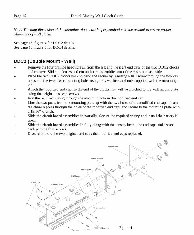
Note: The long dimension of the mounting plate must be perpendicular to the ground to assure proper
alignment of wall clocks.
See page 15, figure 4 for DDC2 details.
See page 16, figure 5 for DDC4 details.
DDC2 (Double Mount - Wall)
» Remove the four phillips head screws from the left and the right end caps of the two DDC2 clocks
and remove. Slide the lenses and circuit board assemblies out of the cases and set aside.
» Place the two DDC2 clocks back to back and secure by inserting a #10 screw through the two key
holes and the two lower mounting holes using lock washers and nuts supplied with the mounting
kit.
» Attach the modified end caps to the end of the clocks that will be attached to the wall mount plate
using the original end cap screws.
» Run the required wiring through the matching hole in the modified end cap.
» Line the two posts from the mounting plate up with the two holes of the modified end caps. Insert
the chase nipples through the holes of the modified end caps and secure to the mounting plate with
a 15/16" wrench.
» Slide the circuit board assemblies in partially. Secure the required wiring and install the battery if
used.
» Slide the circuit board assemblies in fully along with the lenses. Install the end caps and secure
each with its four screws.
» Discard or store the two original end caps the modified end caps replaced.
DDC2 cases
modified end caps
#10 screws
#10 lock washers
#10 lock washers
#10 hex nuts
mounting plate
chase nipples
Figure 4

Digital Display Wall Clock Guide Page 16
DDC4 (Double Mount - Wall)
» Remove the two phillips head screws from the left and the right end caps of the two DDC4 clocks
and remove. Slide the front panel assemblies out of the cases and set aside.
» Place the two DDC4 clocks back to back and secure by inserting a #10 screw through the two key
holes and the two lower mounting holes using lock washers and nuts supplied with the mounting
kit.
» Attach the modified end cap to the end of the clocks that will be attached to the wall mount plate
using the original end cap screws.
» Align the holes of the end cap support plate with the holes in the modified end cap and secure with
4 #6 phillips head screws (supplied)
» Line the two posts from the mounting plate up with the two holes of the modified end cap. Insert
the chase nipples through the holes of the modified end cap and secure to the mounting plate with
a 15/16" wrench.
» Slide the front panel assemblies in partially. Secure the required wiring and install the battery if
used.
» Slide the front panel assemblies in fully. Install the end caps and secure each with its two screws.
» Discard or store the two original end caps the modified end cap replaced.
mounting plate
#10 lock washers
#10 screws
end cap support
chase nipples
modified end caps
DDC4 cases
#10 lock washers#10 hex nuts
Figure 5

Page 17 Digital Display Wall Clock Guide
Double Mount - Ceiling
Requires optional mounting kit (SAM0626)
Tools required for mounting the clock:
Flat blade screwdriver
Phillips head screwdriver
15/16" open end wrench
The double ceiling mount plate attaches to a double or single gang box installed securely in the ceiling.
Required wiring should be available through the gang box at time of installation.
» Remove the two chase nipples from the mounting plate posts.
» Run the required wiring from the gang box through one of the mounting posts of the mounting
plate.
» Secure the mounting plate securely to the gang box with the proper screws. (not supplied)
Note: When mounting DDC2 clocks, the short side of the mounting plate must be parallel to the long side
of the clocks. When mounting DDC4 clocks, the long side of the mounting plate must be parallel to the long
side of the clocks.
See page 18, figure 6 for DDC2 details.
See page 19, figure 7 for DDC4 details

Digital Display Wall Clock Guide Page 18
DDC2 (Double Mount - Ceiling)
Note: Make sure you have at least 10 1/2" of side clearance on one side in order to remove the lens and
circuit board assembly.
» Remove the four phillips head screws from the left and the right end caps of the two DDC2 clocks
and remove. Slide the lenses and circuit board assemblies out of the cases and set aside.
» Place the two DDC2 clocks back to back and secure by inserting a #10 screw through the two key
holes and the two lower mounting holes using lock washers and nuts supplied with the mounting
kit. Note: At this point, if the DDC2 clocks will be mounted too near a wall on one side to secure
the end caps, install the "wall side" end caps now.
» Remove the center vent cap from the top of each DDC2 clock.
» Line the two posts from the mounting plate up with the vent holes of the DDC2 clocks. Insert the
chase nipples through the vent holes and secure to the mounting plate with a 15/16" wrench.
» Slide the circuit board assemblies in partially. Secure the required wiring and install the battery if
used.
» Slide the circuit board assemblies in fully along with the lenses. Install the end caps and secure
each with its four screws.
Note: When mounting DDC2 clocks, the
short side of the mounting plate must be
parallel to the long side of the clocks
mounting plate
#10 screws#10 lock washers
mounting plate
DDC2 cases
#10 screws
#10 hex nuts
#10 lock washers
chase nipple
chase nipple
Figure 6
Page 19 Digital Display Wall Clock Guide
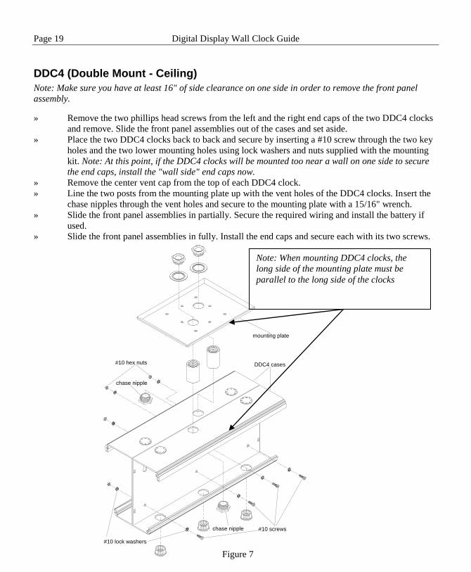
DDC4 (Double Mount - Ceiling)
Note: Make sure you have at least 16" of side clearance on one side in order to remove the front panel
assembly.
» Remove the two phillips head screws from the left and the right end caps of the two DDC4 clocks
and remove. Slide the front panel assemblies out of the cases and set aside.
» Place the two DDC4 clocks back to back and secure by inserting a #10 screw through the two key
holes and the two lower mounting holes using lock washers and nuts supplied with the mounting
kit. Note: At this point, if the DDC4 clocks will be mounted too near a wall on one side to secure
the end caps, install the "wall side" end caps now.
» Remove the center vent cap from the top of each DDC4 clock.
» Line the two posts from the mounting plate up with the vent holes of the DDC4 clocks. Insert the
chase nipples through the vent holes and secure to the mounting plate with a 15/16" wrench.
» Slide the front panel assemblies in partially. Secure the required wiring and install the battery if
used.
» Slide the front panel assemblies in fully. Install the end caps and secure each with its two screws.
Note: When mounting DDC4 clocks, the
long side of the mounting plate must be
parallel to the long side of the clocks
chase nipple
chase nipple
#10 screws
#10 lock washers
#10 hex nuts
mounting plate
DDC4 cases
Figure 7

Digital Display Wall Clock Guide Page 20
Setting the Time Time is set on the DDC Series Wall Clocks by depressing buttons located on the left side of the front panel.
There are two setting buttons, "H" for hour and "M' for minute.
» To advance the hour or minute to the correct time one digit at a time press and release the proper
button. Do this as many times as required until the correct time is displayed. When setting the
hour, if the display is set to 12 Hour, a "dot" in the upper left corner of the display represents the
PM hours.
» To rapidly advance the hour or minute press and hold the proper button. Release the button when
the correct time is displayed. When setting the hour, if the display is set to 12 Hour, a "dot" in the
upper left corner of the display represents the PM hours.
Note: Setting the minutes past 59 will not cause the hour to advance.
Note: Avoid using sharp or pointed objects to set the time as damage to the buttons may occur. A standard
pencil eraser is suggested.
Time Formats
The DDC2 / DDC4 Series Wall Clocks can be set to display in 12 Hour or 24 Hour format. When in 12-
Hour format, a round LED in the upper left corner of the display indicates PM hours. When in 24 Hour
format, the hours are displayed in Military style. To set the display format, use Table 3 on page 4 to set
switch 8 of S1.
Note: When switches 1-5 are set for any secondary type other than Stand-Alone, the display is forced to 12
Hour and the PM indicator does not illuminate.
12 Hour Format
24 Hour Format AM PM
H
M
H
M
H
M
Page 21 Digital Display Wall Clock Guide DDC2 / 4-RS Wiring
Appendix A - DDC2-RS / 4-RS Secondary Clock Wiring Diagrams Note: See Appendix B for DDC2-RS-24 / DDC4-RS-24 wiring.
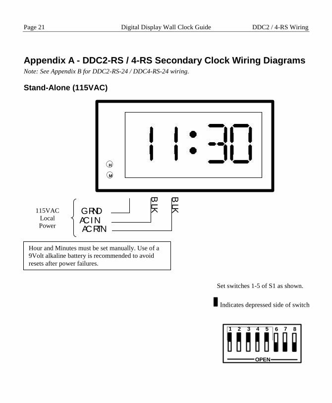
Stand-Alone (115VAC)
GRNDAC INAC RTN
BLK
BLK
115VAC
Local
Power
Set switches 1-5 of S1 as shown.
Indicates depressed side of switch
OPEN
1 2 3 4 5 6 7 8
H
M
Hour and Minutes must be set manually. Use of a
9Volt alkaline battery is recommended to avoid
resets after power failures.

DDC2 / 4-RS Wiring Digital Display Wall Clock Guide Page 22
3-Wire Synchronous (115VAC)
OPEN
1 2 3 4 5 6 7 8
Set switches 1-5 of S1 as shown.
Indicates depressed side of switch Wiring applies to secondary wall clocks such as:
Lathem type SS Cincinnati D10 IBM 77 Series
Simplex 77 Series, 93-9, 91-9, 941-9, 943-9
Stromberg 3000
To
Other Clocks
115VAC
From
Master Clock
H
M
BLU
/ WH
T
Run
Correct ion
BR
N / W
HT
BLK
BLK
AC Return
Clock will correct minutes hourly at HH:59 and
hour and minutes twice daily at 5:59.

Page 23 Digital Display Wall Clock Guide DDC2 / 4-RS Wiring
3-Wire Synchronous (24VAC Correction)
OPEN
1 2 3 4 5 6 7 8
Set switches 1-5 of S1 as shown.
Indicates depressed side of switch Wiring applies to secondary wall clocks such as:
Lathem type SS Cincinnati D10 IBM 77 Series
Simplex 77 Series, 93-9, 91-9, 941-9, 943-9
Stromberg 3000
To
Other Clocks
24VAC
From
Master Clock
H
M
115VAC
Local
Power
BLU
/ WH
T
Correct ion
BR
N / W
HT
Return
GRNDAC INAC RTN
BLK
BLK
Clock will correct minutes hourly at HH:59 and
hour and minutes twice daily at 5:59.

DDC2 / 4-RS Wiring Digital Display Wall Clock Guide Page 24
3-Wire minute Impulse (59th Minute)
Wiring applies to secondary wall clocks such as:
Lathem ISC 3-Wire Standard Impulse Cincinnati D2, D4
Stromberg Impulse Edwards Impulse Faraday Impulse
Simplex 75 Series, 91-4, 93-4, 941-4, 943-4 IBM 75 Series
OPEN
1 2 3 4 5 6 7 8
Set switches 1-5 of S1 as shown.
Indicates depressed side of switch
BR
N / W
HT
GRNDAC INAC RTN
ABC
VIO
/ WH
T
YE
L / WH
T
BLK
BLK
To
Other Clocks
24VDC
From
Master Clock
115VAC
Local
Power
H
M
Clock must be set within 20 minutes of actual time
for master to synchronize. Use of a 9Volt alkaline
battery is recommended to avoid resets after power
failures.

Page 25 Digital Display Wall Clock Guide DDC2 / 4-RS Wiring
3-Wire Minute Impulse (59th Minute With 12 Hour Correction)
BR
N / W
HT
GRNDAC INAC RTN
ABC
VIO
/ WH
T
YE
L / WH
T
BLK
BLK
Wiring applies to secondary wall clocks such as:
Lathem ISC 3-Wire 12Hour Simplex 91, 941
Set switches 1-5 of S1 as shown.
Indicates depressed side of switch
OPEN
1 2 3 4 5 6 7 8
To
Other Clocks
24VDC
From
Master Clock
115VAC
Local
Power
H
M
Clock will correct minutes hourly at HH:58 and
hour and minutes twice daily at 5:58.

DDC2 / 4-RS Wiring Digital Display Wall Clock Guide Page 26
Standard Electric Synchronous
To
Other Clocks
115VAC
From
Master Clock
OPEN
1 2 3 4 5 6 7 8
Set switches 1-5 of S1 as shown.
Indicates depressed side of switch
H
M
For 24VAC correction, use wiring
shown on page 23
BLU
/ WH
T
Run
Correct ion
BR
N / W
HT
BLK
BLK
AC Return
Clock will correct minutes hourly at HH:59 and
hour and minutes twice daily at 5:12.
Page 27 Digital Display Wall Clock Guide DDC2 / 4-RS Wiring
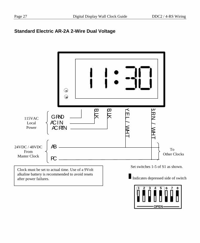
Standard Electric AR-2A 2-Wire Dual Voltage
BR
N / W
HT
GRNDAC INAC RTN
AB
PC
YE
L / WH
T
BLK
BLK
To
Other Clocks
24VDC / 48VDC
From
Master Clock
115VAC
Local
Power
OPEN
1 2 3 4 5 6 7 8
Set switches 1-5 of S1 as shown.
Indicates depressed side of switch
H
M
Clock must be set to actual time. Use of a 9Volt
alkaline battery is recommended to avoid resets
after power failures.

DDC2 / 4-RS Wiring Digital Display Wall Clock Guide Page 28
Standard Electric AR-2 2-Wire Dual Voltage
BR
N / W
HT
GRNDAC INAC RTN
AB
PC
YE
L / WH
T
BLK
BLK
To
Other Clocks
24VDC / 48VDC
From
Master Clock
115VAC
Local
Power
OPEN
1 2 3 4 5 6 7 8
Set switches 1-5 of S1 as shown.
Indicates depressed side of switch
H
M
Clock must be set to actual time. Use of a 9Volt
alkaline battery is recommended to avoid resets
after power failures.

Page 29 Digital Display Wall Clock Guide DDC2 / 4-RS Wiring
Synchronous Wired
To
Other Clocks
115VAC
From
Master Clock
OPEN
1 2 3 4 5 6 7 8
Set switches 1-5 of S1 as shown.
Indicates depressed side of switch
Wiring applies to secondary wall clocks such as:
Cincinnati D8 Faraday Honeywell ST402A
H
M
For 24VAC correction, use wiring
shown on page 23
BLU
/ WH
T
Run
Correct ion
BR
N / W
HT
BLK
BLK
AC Return
Clock will correct minutes hourly at HH:58 and
hour and minutes twice daily beginning at 5:05.

DDC2 / 4-RS Wiring Digital Display Wall Clock Guide Page 30
Simplex 59th Minute Dual Motor
To
Other Clocks
115VAC
From
Master Clock
OPEN
1 2 3 4 5 6 7 8
Set switches 1-5 of S1 as shown.
Indicates depressed side of switch
H
M
For 24VAC correction, use wiring
shown on page 23
BLU
/ WH
T
Run
Correct ion
BR
N / W
HT
BLK
BLK
AC Return
Clock must be set to proper hour. Clock will
correct minutes hourly at HH:58. . Use of a 9Volt
alkaline battery is recommended to avoid resets
after power failures.

Page 31 Digital Display Wall Clock Guide DDC2 / 4-RS Wiring
Simplex 45th Minute Dual Motor
To
Other Clocks
115VAC
From
Master Clock
OPEN
1 2 3 4 5 6 7 8
Set switches 1-5 of S1 as shown.
Indicates depressed side of switch
H
M
For 24VAC correction, use wiring
shown on page 23
BLU
/ WH
T
Run
Correct ion
BR
N / W
HT
BLK
BLK
AC Return
Clock must be set to proper hour. Clock will
correct minutes hourly at HH:45. . Use of a 9Volt
alkaline battery is recommended to avoid resets
after power failures.

DDC2 / 4-RS Wiring Digital Display Wall Clock Guide Page 32
Edwards Dual Motor
To
Other Clocks
115VAC
From
Master Clock
OPEN
1 2 3 4 5 6 7 8
Set switches 1-5 of S1 as shown.
Indicates depressed side of switch
H
M
For 24VAC correction, use wiring
shown on page 23
BLU
/ WH
T
Run
Correct ion
BR
N / W
HT
BLK
BLK
AC Return
Clock must be set to actual time. Use of a 9Volt
alkaline battery is recommended to avoid resets
after power failures.

Page 33 Digital Display Wall Clock Guide DDC2 / 4-RS Wiring
Standard Electric AR-3 3-Wire Minute Impulse
To
Other Clocks
24VDC / 48VDC
From
Master Clock
115VAC
Local
Power
OPEN
1 2 3 4 5 6 7 8
Set switches 1-5 of S1 as shown.
Indicates depressed side of switch
BR
N/ W
HT
24 VDC Pulse
Common
YE
L / WH
T
48 VDC Correct ion
GRNDAC INAC RTN
BLK
BLK
VIO
/ WH
T
H
M
Clock must be set to actual time. Use of a 9Volt
alkaline battery is recommended to avoid resets
after power failures.
DDC2 / 4-RS Wiring Digital Display Wall Clock Guide Page 34
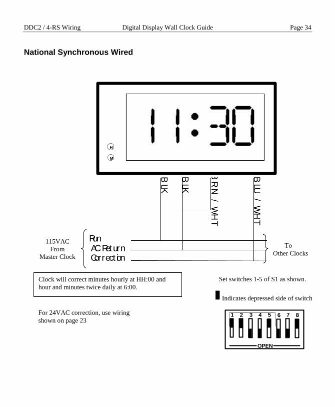
National Synchronous Wired
To
Other Clocks
115VAC
From
Master Clock
OPEN
1 2 3 4 5 6 7 8
Set switches 1-5 of S1 as shown.
Indicates depressed side of switch
H
M
For 24VAC correction, use wiring
shown on page 23
BLU
/ WH
T
Run
Correct ion
BR
N / W
HT
BLK
BLK
AC Return
Clock will correct minutes hourly at HH:00 and
hour and minutes twice daily at 6:00.
Page 35 Digital Display Wall Clock Guide DDC2 / 4-RS Wiring
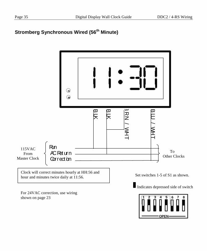
Stromberg Synchronous Wired (56th Minute)
To
Other Clocks
115VAC
From
Master Clock
OPEN
1 2 3 4 5 6 7 8
Set switches 1-5 of S1 as shown.
Indicates depressed side of switch
H
M
For 24VAC correction, use wiring
shown on page 23
BLU
/ WH
T
Run
Correct ion
BR
N / W
HT
BLK
BLK
AC Return
Clock will correct minutes hourly at HH:56 and
hour and minutes twice daily at 11:56.

DDC2 / 4-RS Wiring Digital Display Wall Clock Guide Page 36
Cincinnati D1
BR
N / W
HT
GRNDAC INAC RTN
A
COMMON
YE
L / WH
T
BLK
BLK
To
Other Clocks
24VDC / 60VDC
From
Master Clock
115VAC
Local
Power
OPEN
1 2 3 4 5 6 7 8
Set switches 1-5 of S1 as shown.
Indicates depressed side of switch
H
M
Clock must be set within 20 minutes of actual time
for master to synchronize. Use of a 9Volt alkaline
battery is recommended to avoid resets after power
failures.

Page 37 Digital Display Wall Clock Guide DDC2 / 4-RS Wiring
Cincinnati D6, Edwards 2406
AB
PC
YE
L / WH
T
GRNDAC INAC RTN
BLK
BLK
VIO
/ WH
T
To
Other Clocks
24-36VDC
From
Master Clock
115VAC
Local
Power
OPEN
1 2 3 4 5 6 7 8
Set switches 1-5 of SW1 as
shown.
Indicates depressed side of
switch
Set switches 1-5 of S1 as shown.
Indicates depressed side of switch
H
M
Clock must be set within 20 minutes of actual time
for master to synchronize. Use of a 9Volt alkaline
battery is recommended to avoid resets after power
failures.

DDC2 / 4-RS Wiring Digital Display Wall Clock Guide Page 38
2-Wire Pulse Alternating (24VDC)
OPEN
1 2 3 4 5 6 7 8
Set switches 1-5 of S1 as shown.
Indicates depressed side of switch
A
B
YE
L / WH
T
GRNDAC INAC RTN
BLK
BLK
VIO
/ WH
T
To
Other Clocks
24VDC
From
Master Clock
115VAC
Local
Power
H
M
Clock must be set within 20 minutes of actual time
for master to synchronize. Use of a 9Volt alkaline
battery is recommended to avoid resets after power
failures.

Page 39 Digital Display Wall Clock Guide DDC2 / 4-RS Wiring
Electronic Coded
BR
N / W
HT
GRNDAC INAC RTN
BLU
/ WH
T
BLK
BLK
REDGRAY
WH
T
3510 Hz
Reciever
115VAC
Local
Power
OPEN
1 2 3 4 5 6 7 8
Set switches 1-5 of S1 as shown.
Indicates depressed side of switch
H
M
Requires 3510Hz receiver (not supplied)
Clock will correct minutes hourly at HH:57 and
hour and minutes twice daily at 5:57.

DDC2 / 4-RS Wiring Digital Display Wall Clock Guide Page 40
Straight Frequency
BR
N / W
HT
GRNDAC INAC RTN
BLU
/ WH
T
BLK
BLK
REDGRAY
WH
T
3510 Hz
Reciever
115VAC
Local
Power
OPEN
1 2 3 4 5 6 7 8
Set switches 1-5 of S1 as shown.
Indicates depressed side of switch
H
M
Requires 3510Hz receiver (not supplied)
Clock will correct minutes hourly at HH:57 and
hour and minutes twice daily at 5:57.
Page 41 Digital Display Wall Clock Guide DDC2 / 4-RS Wiring
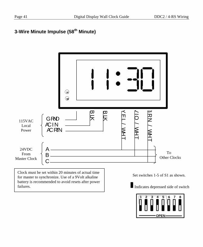
3-Wire Minute Impulse (58th Minute)
BR
N / W
HT
GRNDAC INAC RTN
ABC
VIO
/ WH
T
YE
L / WH
T
BLK
BLK
To
Other Clocks
24VDC
From
Master Clock
115VAC
Local
Power
OPEN
1 2 3 4 5 6 7 8
Set switches 1-5 of S1 as shown.
Indicates depressed side of switch
H
M
Clock must be set within 20 minutes of actual time
for master to synchronize. Use of a 9Volt alkaline
battery is recommended to avoid resets after power
failures.

DDC2 / 4-RS Wiring Digital Display Wall Clock Guide Page 42
3-Wire Minute Impulse (44th Minute)
BR
N / W
HT
GRNDAC INAC RTN
ABC
VIO
/ WH
T
YE
L / WH
T
BLK
BLK
To
Other Clocks
24VDC
From
Master Clock
115VAC
Local
Power
OPEN
1 2 3 4 5 6 7 8
Set switches 1-5 of S1 as shown.
Indicates depressed side of switch
H
M
Clock must be set within 20 minutes of actual time
for master to synchronize. Use of a 9Volt alkaline
battery is recommended to avoid resets after power
failures.

Page 43 Digital Display Wall Clock Guide DDC2 / 4-RS Wiring
2-Wire Reverse Polarity Minute Impulse (59th Minute)
AB
PC
YE
L / WH
T
GRNDAC INAC RTN
BLK
BLK
VIO
/ WH
T
To
Other Clocks
24VDC
From
Master Clock
115VAC
Local
Power
OPEN
1 2 3 4 5 6 7 8
Set switches 1-5 of S1 as shown.
Indicates depressed side of switch
H
M
Clock must be set within 20 minutes of actual time
for master to synchronize. Use of a 9Volt alkaline
battery is recommended to avoid resets after power
failures.

DDC2 / 4-RS -24 Wiring Digital Display Wall Clock Guide Page 44
Appendix B - DDC2-RS-24 / DDC4-RS-24 Wiring The DDC2-RS-24 and the DDC4-RS-24 allow for 24VAC supplied from the Master Clock or Power
Supply to power it for normal operation. These models can be used in installations where local 115VAC
power may not be available. When shipped, the DDC2-RS-24 and DDC4-RS-24 have an optional power
transformer that allows for 24VAC operation.
The 24VAC power from the Master Clock or Power Supply should be connected to the two black wires
leading from J1. (See figure 7 below for location of J1)
Correction wiring should be applied according to the secondary type selection as shown in Appendix A.
CAUTION: Applying any voltage higher than 24VAC to the input (two black leads
from J1) WILL cause damage to the DDC2-RS-24 and DDC4-RS-24 clocks.
Figure 7
JP2
Hours
Minutes
Up
Down
J4
J3
J1
OPEN
1 2 3 4 5 6 7 8
DIP Switch
S1
9VDC Alkaline Battery
Cradle
- +
Lathem Time Corp.
DDC2\4 (E-PROM)
Jumper
J2
Ground
Beeper
D-
D+
JP4
JP1
JP3
Fly Lead
Connector

Page 45 Digital Display Wall Clock Guide DDC2 / 4-RS -24 Wiring
DDC2-RS-24 / DDC4-RS-24 Wiring
H
M
OPEN
1 2 3 4 5 6 7 8
Set switches 1-5 of S1 as shown.
Indicates depressed side of switch
To
Other Clocks
24VAC
From
Master Clock
BLU
/ WH
T
Run
Correct ion
BR
N / W
HT
BLK
BLK
AC Return

DDC2 / 4-RS -485 Wiring Digital Display Wall Clock Guide Page 46
Appendix C - RS485 Wiring Diagrams
RS485 Data Format
The data string that sends the time to the DDC2 / DDC4 Series Wall Clocks is formatted in such a manner
that a utility can be written to achieve time updates from a personal computer. The following table shows
the layout and explains each character.
Data Format
0#112233445566777Z,CR
The data string is compiled of a total of 16 characters. These characters represent the following.
0 Address byte
# Command for Time update
11 Hex for Seconds (01-59)
22 Hex for Minutes (00-59)
33 Hex for Hour (00-23)
44 Hex for Day of Week (Sunday = 0)
55 Hex for Month (01-12)
66 Hex for Date (01-31)
777 Hex for Year offset from 1984 (000-127)
Z The Checksum (1's compliment of the mod-64 sum of all characters in the string except the CR and
the Checksum)
CR Carriage Return
Transfer of the above string must be done at 9600 Baud, 8 Data Bits, 1 Stop Bit and No Parity.
Requires the SWIFT-485 plus to convert the RS232 signal from the PC to RS485 to send data to the DDC
Series Wall Clocks.
Note: Lathem does not offer a utility to perform this function. This information is supplied so that a 3rd
party may create such a utility.

Page 47 Digital Display Wall Clock Guide DDC2 / 4-RS -485 Wiring
OMCII to DDC2-RS / 4-RS
Pin Signal Signal JP4 Connection
1 Transmit Data (-) Transmit Data (-) D-
2 Transmit Data (+) Transmit Data (+) D+
8 Signal Ground Signal Ground GND
To
Other Clocks
BLK
BLK
115VAC
Local
Power
OMCII DB9 Female Plug
Cable should be RS232 twisted pair / CAT3 or CAT5 type.
Maximum distance to last DDC Clock is 4000 feet.
Last DDC Clock must have jumper installed on position J2.
See page 8 for details.
Set switches 1-5 of S1 as shown.
Indicates depressed side of switch
OPEN
1 2 3 4 5 6 7 8
11 30
OMC II
GN
D o
f JP
4
D- o
f JP
4
D+
of J
P4
GN
DT
ran
s +
Tra
ns -
:
H
M
DDC2-RS / 4-RS - JP4 Connector

DDC2 / 4-RS -485 Wiring Digital Display Wall Clock Guide Page 48
LTR0 to DDC2-RS / 4-RS
Wire Signal Signal JP4 Connection
Gray Transmit Data (-) Transmit Data (-) D-
Orange Transmit Data (+) Transmit Data (+) D+
Black Signal Ground Signal Ground GND
BLK
BLK
115VAC
Local
Power
To
Other Clocks
LTR0 Fly Leads
Cable should be RS232 twisted pair / CAT3 or CAT5 type.
Maximum distance to last DDC Clock is 4000 feet.
Last DDC Clock must have jumper installed on position J2.
See page 8 for details.
Set switches 1-5 of S1 as shown.
Indicates depressed side of switch
OPEN
1 2 3 4 5 6 7 8
H
M
LTR 0
BL
KO
RN
GR
Y
GN
D o
f JP
4
D- o
f JP
4
D+
of J
P4
DDC2-RS / 4-RS - JP4 Connector

Page 49 Digital Display Wall Clock Guide DDC2 / 4-RS -485 Wiring
LTR4 / 8-512 to DDC2-RS / 4-RS
Terminal # Signal Signal JP4 Connection
9 (D-) Transmit Data (-) Transmit Data (-) D-
8 (D+) Transmit Data (+) Transmit Data (+) D+
BLK
BLK
115VAC
Local
Power
To
Other Clocks
LTR4 / 8-512 Terminal Connections
Cable should be RS232 twisted pair / CAT3 or CAT5 type.
Maximum distance to last DDC Clock is 4000 feet.
Last DDC Clock must have jumper installed on position J2.
See page 8 for details.
Set switches 1-5 of S1 as shown.
Indicates depressed side of switch
OPEN
1 2 3 4 5 6 7 8
DDC2-RS / 4-RS - JP4 Connector
LTR4 / 8-512D+
D-
D- o
f JP
4
D+
of J
P4
11 30:
H
M
DDC-TC Timer Control Panel Digital Display Wall Clock Guide Page 50
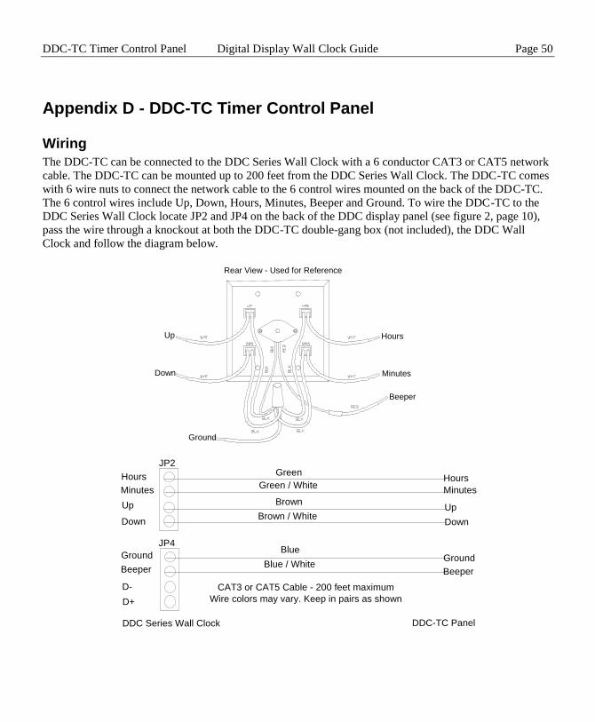
Appendix D - DDC-TC Timer Control Panel
Wiring
The DDC-TC can be connected to the DDC Series Wall Clock with a 6 conductor CAT3 or CAT5 network
cable. The DDC-TC can be mounted up to 200 feet from the DDC Series Wall Clock. The DDC-TC comes
with 6 wire nuts to connect the network cable to the 6 control wires mounted on the back of the DDC-TC.
The 6 control wires include Up, Down, Hours, Minutes, Beeper and Ground. To wire the DDC-TC to the
DDC Series Wall Clock locate JP2 and JP4 on the back of the DDC display panel (see figure 2, page 10),
pass the wire through a knockout at both the DDC-TC double-gang box (not included), the DDC Wall
Clock and follow the diagram below.
Beeper
Ground
Minutes
HoursUp
Down
Rear View - Used for Reference
DDC Series Wall Clock
JP2
JP4
Ground
Beeper
Down
Up
Minutes
Hours
DDC-TC Panel
CAT3 or CAT5 Cable - 200 feet maximum
Ground
Beeper
Down
Up
Minutes
Hours
D-
D+
Green
Green / White
Brown
Blue
Blue / White
Brown / White
Wire colors may vary. Keep in pairs as shown

Page 51 Digital Display Wall Clock Guide DDC-TC Timer Control Panel
Installation
The DDC-TC mounts directly to a standard, double-gang wall box. (not included) Once the wiring has been
attached, place the wires inside the double-gang wall box and mount the DDC-TC to the box with the four
screws supplied with the DDC-TC by inserting them through the mounting holes and securing.
Mounting Holes
Mounting Holes
S et Hours
S top / Continue
Count Down
S tart 00:00
Quit
S et Minutes
S top / Continue
S tart HH:MM
Count Up
TIME R CONTROL

DDC-TC Timer Control Panel Digital Display Wall Clock Guide Page 52
Operation
As a Count Up Timer
To start the count: press Count Up
To pause the count: press Stop / Continue
To continue the count: press Stop / Continue
To return to clock mode: press Quit
As a Count Down Timer
To set hours: press Set Hours (defualt is 00: )
To set minutes: press Set Minutes (defualt is :00)
To start the count: press Count Down
To pause the count: press Stop / Continue
To continue the count: press Stop / Continue
To return to clock mode: press Quit
Note: To pause and continue, press the corresponding Stop / Continue button that started the operation.
In the Count Down mode, when 00:00 is reached, an audible tone will sound and the display will return to
clock mode.
When in Count Up or Count Down mode, when the time being counted is greater than 60 minutes the
display will read HH:MM. When the time being counted reaches less than 60 minutes, the display will read
MM:SS.

Page 53 Digital Display Wall Clock Guide Specifications
Appendix E - LTR-GPS Satellite Receiver / Clock Synchronizer
Lathem’s LTR-GPS is a Global Positioning Satellite receiver using 12-channels to access the accurate date
and time signal transmitted each second by 24 satellites in geosynchronous orbit around the globe.
The package includes an amplified GPS Antenna, which must be mounted out-doors or beneath a roof sky-
light, facing skyward. An integrated cable links the Antenna to the LTR-GPS Receiver Module, which
should be mounted in-doors.
The Receiver Module verifies and reformats the received satellite data, and offers multiple synchronization
protocol outputs:
The RS-485 Output can directly synchronize up to 31 Lathem time products, up to 4000ft away, over a
single twisted-pair from a user-provided Cat-3 or Cat-5 cable. The length of cable and number of
synchronized devices can be further increased using Lathem’s “SWIFT485+” RS-485 Converter / Repeater.
The supported products include:
LTR-0 Master Clock 1-Clock Ctl
DWA-S Sonochron 1-Bell Ckt
LTR4-512 Master Clock 1-Clk + 2-Ckt
LTR8-512 Master Clock 1-Clk + 6-Ckt
LTR8-512M Master Clock w/ Modem
DDC2-RS 2” Digital Wall Clock 115v
DDC2-RS-24 2” Digital Wall Clock 24v
DDC4-RS 4” Digital Wall Clock 115v
DDC4-RS-24 4” Digital Wall Clock 24v
An included RS-232 interface provides a periodic “Time Stamp” transmission, “MM-DD-YYYY
HH:MM:SS cr”, for use by computing systems having custom software to incorporate accurate date and
time records in their applications: 9600,N,8,1. Use of this option requires Lathem cable, Part No.
SAE0370, to be ordered separately.
Simple DIP-Switch set-up enables the installer to specify local Time Zone, Daylight Savings Time
corrections, and output formats. An LED indicator shows Signal Reception / Protocol Mode.
The LTR-GPS may receive its power from an LTRx-512-series Master Clock, using 2nd
cable pair, if the
distance is less than 200ft; else, power is provided locally by a 9vAC Power Adapter.

Warranty Digital Display Wall Clock Guide Page 54
The LTR-GPS package includes:
LTR-GPS Satellite Synchronizer
115vAC, 2.7w, 50/60Hz Power Adapter
Active GPS Antenna with 25ft. Cable
Antenna Mounting Bracket and Hardware
Installation and Set-Up Guide
Separately, from Lathem, for Installer convenience:
GPS-INSTALL-TOOLS: Battery / Beeper assemblies aid in Antenna positioning
LTR-GPS Specifications:
Size / Weight 3.25”x 2”x6.6” / 1 lb.
Power: 6-12vAC/DC, 300mA (max)
Certificates: FCC Part-15, ICES003
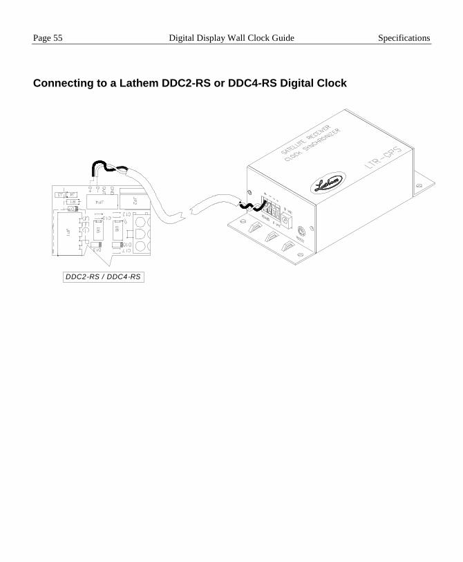
Page 55 Digital Display Wall Clock Guide Specifications
Connecting to a Lathem DDC2-RS or DDC4-RS Digital Clock
DDC2-RS / DDC4-RS
Warranty Digital Display Wall Clock Guide Page 56
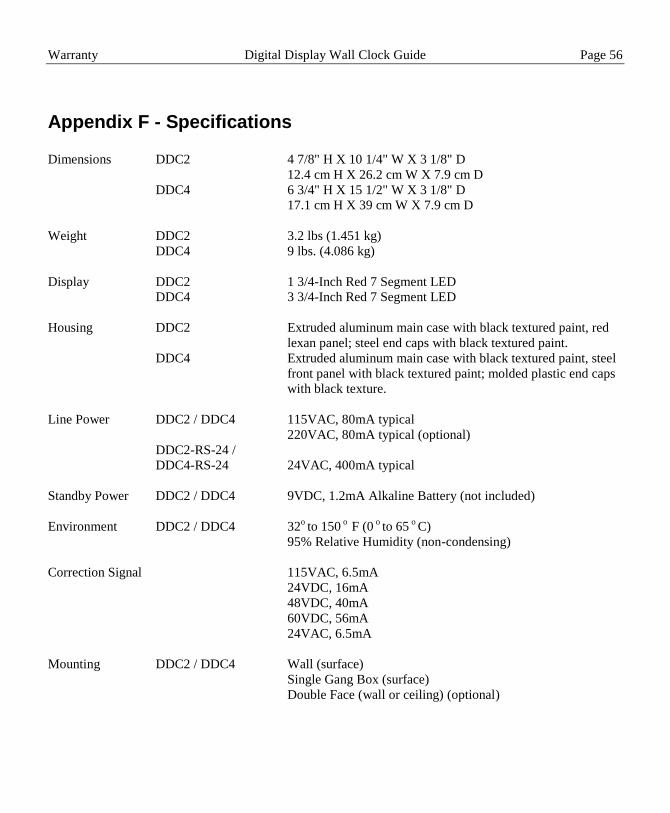
Appendix F - Specifications
Dimensions DDC2 4 7/8" H X 10 1/4" W X 3 1/8" D
12.4 cm H X 26.2 cm W X 7.9 cm D
DDC4 6 3/4" H X 15 1/2" W X 3 1/8" D
17.1 cm H X 39 cm W X 7.9 cm D
Weight DDC2 3.2 lbs (1.451 kg)
DDC4 9 lbs. (4.086 kg)
Display DDC2 1 3/4-Inch Red 7 Segment LED
DDC4 3 3/4-Inch Red 7 Segment LED
Housing DDC2 Extruded aluminum main case with black textured paint, red
lexan panel; steel end caps with black textured paint.
DDC4 Extruded aluminum main case with black textured paint, steel
front panel with black textured paint; molded plastic end caps
with black texture.
Line Power DDC2 / DDC4 115VAC, 80mA typical
220VAC, 80mA typical (optional)
DDC2-RS-24 /
DDC4-RS-24 24VAC, 400mA typical
Standby Power DDC2 / DDC4 9VDC, 1.2mA Alkaline Battery (not included)
Environment DDC2 / DDC4 32o to 150
o F (0
o to 65
o C)
95% Relative Humidity (non-condensing)
Correction Signal 115VAC, 6.5mA
24VDC, 16mA
48VDC, 40mA
60VDC, 56mA
24VAC, 6.5mA
Mounting DDC2 / DDC4 Wall (surface)
Single Gang Box (surface)
Double Face (wall or ceiling) (optional)

Page 57 Digital Display Wall Clock Guide Specifications
Appendix G - Warranty
Limited One-Year Limited Warranty
Lathem warrants the hardware products described in this guide against defects in material and workmanship for a period of
one year from date of original purchase from Lathem or from an authorized Lathem reseller. The conditions of this warranty
and the extent of the responsibility of Lathem Time Corporation (“Lathem”) under this warranty are listed below.
1. This warranty will become void when service performed by anyone other than an approved Lathem warranty
service dealer results in damage to the product.
2. This warranty does not apply to any product which has been subject to abuse, neglect, or accident, or which has
had the serial number altered or removed, or which has been connected, installed, adjusted, or repaired other
than in accordance with instructions furnished by Lathem.
3. This warranty does not cover dealer labor cost for removing and reinstalling the machine for repair, or any
expendable parts that are readily replaced due to normal use.
4. The sole responsibility of Lathem under this warranty shall be limited to repair of this product, or replacement
thereof, at the sole discretion of Lathem.
5. If it becomes necessary to send the product or any defective part to Lathem or any authorized service dealer, the
product must be shipped in its original carton or equivalent, fully insured with shipping charges prepaid.
Lathem will not assume any responsibility for any loss or damage incurred in shipping.
6. WARRANTY DISCLAIMER AND LIMITATION OF LIABILITY: Except only the limited express warranty
set forth above, the products are sold with no expressed or implied warranties of any kind, and the implied
warranties of merchantability and fitness for a particular purpose are hereby expressly disclaimed. No
warranties are given with respect to products purchased other than from Lathem or an authorized Lathem
reseller and any such products are purchased "as is, with all faults." In no event will Lathem be liable for any
direct, indirect, special, incidental or consequential damages arising out of or in connection with the delivery,
use or inability to use, or performance of this product. In the event any limited remedy given herein shall be
deemed to have failed of its essential purpose, Lathem's maximum liability shall be to refund the purchase price
upon return of the product.
7. Proof of date of purchase from Lathem or an authorized Lathem reseller is required for warranty service on this
product.
8. This Warranty grants specific legal rights. Additional legal rights, which may vary by locale, may also apply.
9. Should any difficulties arise with the performance of this product during warranty, or with any Lathem
authorized service centers, contact Lathem Time at the address below.
Lathem Time
200 Selig Drive, SW, Atlanta, GA 30336
404-691-0405
www.lathem.com
Copyright © 2003 Lathem Time Corporation. All rights reserved.