ct-assisted solid freeform fabrication - dtic.mil applications of ct. of the dozen or so generic...
TRANSCRIPT

Quarterly Status Report No. 8 Report Period: May 1, 1996, through July 31, 1996 Submittal Date: August 15,1996
CT-ASSISTED SOLID FREEFORM FABRICATION
Prepared by: James H. Stanley
Principal Investigator
'--^HJ4i.-\.j.
"~\
.^»«ttm,, Prepared for:
Office of Naval Research 800 North Quincy Street
Arlington, VA 22217-5660 Attention: Dr. Steven G. Fishman
Reference:
Contract Number N00014-94-C-0120 ARACOR Project Number 920
ÖfiSECj^ß,
ADVANCED RESEARCH AND APPLICATIONS CORPORATION 425 Lakeside Drive • Sunnyvale, California 94086-4701 • (408) 733-7780 • FAX (408) 732-1996

1.0 INTRODUCTION
Computed Tomography (CT) is a radiographic inspection method that uses a computer to
reconstruct a cross-sectional image of an object from a set of in-line X-ray transmission
measurements. CT was introduced in the early 1970's as a neurological examination technique and
later extended to industrial applications by Advanced Research and Applications Corporation
(ARACOR) and others. The original medical acronym, CAT, is still widely used and is likely to be
familiar to the reader. The technology provides an ideal examination technique whenever the
primary goal is to locate and size planar or volumetric detail in three dimensions. Because of the
relatively good penetrability of X rays, as well as the sensitivity of absorption cross sections to the
density and atomic number of matter, CT permits the nondestructive physical and, to a limited
extent, chemical characterization of the internal nature of objects. And since the method is X-ray
based, it applies equally well to metallic and non-metallic specimens, solid and fibrous materials,
smooth and irregularly surfaced parts.
A key advantage of CT is that it can nondestructively obtain images of both exterior and
interior surfaces and regions of an object. Because CT images are densitometrically accurate,
complete morphological and part characterization information can be obtained without need for
physical sectioning. With CT, complete 100% examinations can be obtained in a few hours,
independent of part complexity. The data can be processed to create CAD representations of the
part, to extract dimensional measurements, or to detect, size and locate defects. Current industrial
CT systems have progressed to the point where they can provide dimensional measurements of a
part with accuracies competitive with coordinate measuring machines (CMMs). However, unlike
CMMs, CT systems can obtain thousands of measurements simultaneously, without special pre-
programming, of internal as well as external surfaces, while also detecting flaws and defects. And
because CT images are digital, they can be enhanced, analyzed, compressed, archived, retrieved,
input to engineering calculations, and transmitted intramurally via local area network (LAN) or
extramurally via the information super-highway.
As a result of these advantages, CT has emerged in the last few years as the leading
modality for reverse engineering and part characterization applications. In 1988, the Air Force
Wright Laboratory (WL) sponsored a Boeing-ARACOR team to investigate potential industrial
applications of CT. Of the dozen or so generic application areas studied, the use of CT for reverse
engineering and part characterization was ranked as the top commercially viable use. The WL
technical report, "X-Ray Computed Tomography for Casting Development" (WL-TR-92-4032),
concluded that "areas which would benefit [from the use of CT] include internal dimensional
measurements (eliminating destructive sectioning), specific region inspections, flaw
characterization in critical regions (to allow passing or informed repair of castings), and geometric
acquisition for CAD/CAM."
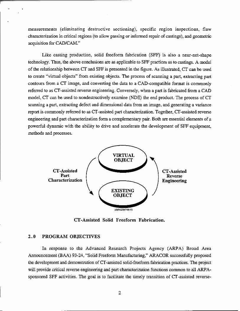
Like casting production, solid freeform fabrication (SFF) is also a near-net-shape
technology. Thus, the above conclusions are as applicable to SFF practices as to castings. A model
of the relationship between CT and SFF is presented in the figure. As illustrated, CT can be used
to create "virtual objects" from existing objects. The process of scanning a part, extracting part
contours from a CT image, and converting the data to a CAD-compatible format is commonly
referred to as CT-assisted reverse engineering. Conversely, when a part is fabricated from a CAD
model, CT can be used to nondestructively examine (NDE) the end product. The process of CT
scanning a part, extracting defect and dimensional data from an image, and generating a variance
report is commonly referred to as CT-assisted part characterization. Together, CT-assisted reverse
engineering and part characterization form a complementary pair. Both are essential elements of a
powerful dynamic with the ability to drive and accelerate the development of SFF equipment,
methods and processes.
CT-Assisted Part
Characterization
CT-Assisted Reverse
Engineering
ARPA2/B674/8-93
CT-Assisted Solid Freeform Fabrication.
2.0 PROGRAM OBJECTIVES
In response to the Advanced Research Projects Agency (ARPA) Broad Area
Announcement (BAA) 93-24, "Solid Freeform Manufacturing," ARACOR successfully proposed
the development and demonstration of CT-assisted solid-freeform fabrication practices. The project
will provide critical reverse engineering and part characterization functions common to all ARPA-
sponsored SFF activities. The goal is to facilitate the timely transition of CT-assisted reverse-

engineering, dimensional verification and defect detection practices to the SFF community. To
meet this goal, the following major technical objectives have been established:
• Develop application software to make CT-assisted manufacturing practices available to
the SFF community. The application will run on a variety of common workstation platforms,
accept data from different CT scanners, and output results in various formats to facilitate reverse
engineering, dimensional verification and report generation. The SFF software tools will be
derived from existing capabilities previously developed for the investment casting industry and
from capabilities defined during interactions with other BAA participants.
• Provide the SFF community access to CT-assisted reverse engineering, dimensional
verification, and defect detection services. Through ARPA, BAA participants will be able to
request access to CT scan and analysis services. Access to high-resolution (< 25(J.) CT scans will
be provided for structural ceramics and other composites needing high-definition nondestructive
evaluation (NDE) imaging, and access to high-energy (~9 MV) CT scans will be provided for
metallic and other components needing large-structure NDE imaging. CAD, dimensional and defect
information will be extracted from image data by ARACOR and provided to other BAA
participants.
• Transfer CT-assisted manufacturing practices to the SFF industry by beta siting
application software and training users in its operation. The SFF application software will be
installed at beta-site locations designated by ARPA and recipients instructed in its use. As directed
by ARPA, ARACOR staff will travel to BAA participant sites to demonstrate the extraction and
analysis of CT-derived data with the proposed SFF application software.
3.0 WORK PLAN
The Work Breakdown Structure (WBS) for the above activities comprises the following
three technical and one management tasks:
Task 1. Develop CT-Assisted SFF Software Application. ARACOR shall develop a
software package to make CT-assisted SFF manufacturing practices universally accessible to
system-level designers. First, ARACOR shall integrate existing ARACOR reverse engineering and
dimensional verification tools into a pre-commercial version of a software application that can run
on a variety of common workstations (WBS 1.1). At a minimum, versions which run on Silicon
Graphics, Sun and IBM workstations will be developed. Following that, ARACOR shall develop
and integrate advanced analysis tools specially for composites produced by SFF techniques into the
application (WBS 1.2). The application will allow users to input CT data from a variety of CT

systems and output results in formats suitable for reverse engineering, dimensional verification and
report generation purposes. The application will feature an intuitive graphical user interface and
networking capabilities for transferring data between workstations. Task 1 will run through years 1
and 2 and will be complete when the beta-site version of the application is ready for release.
Task 2. Provide Access to CT-Assisted Manufacturing Services. ARACOR shall provide
CT-assisted reverse engineering (WBS 2.1), dimensional verification (WBS 2.2) and defect
detection (WBS 2.3) services to the SFF community. Access to high-resolution and high-energy
CT scan services are included. The work plan proposes that all requests for services will be
directed to and approved by ARPA. The work plan assumes that the demand for analysis services
will concentrate in the first two years while the SFF application software is being developed and
will decrease during the third year once other BAA participants are provided beta-site versions of
the necessary CT software tools (see Task 3). The work plan also assumes that scan services will
be provided throughout the three-year SFF program to support third-year technology insertion
efforts. Task 2 will be complete when the level of effort budgeted for these services has been
expended.
Task 3. Transition CT-Assisted Practices to Industry. ARACOR shall install the software
application at beta sites specified by ARPA and train participants in the use of CT-assisted SFF
practices (WBS 3.0). Up to three beta-site locations for the application may be selected. The work
plan proposes that CT scan data be provided as part of Task 2 and that ARACOR travel to
participant sites to provide on-site training and assistance in the application of CT-assisted flaw
detection, dimensional verification and reverse engineering practices. At ARPA's direction,
ARACOR will provide up to twelve trips for staff specialists to BAA participant sites to assist with
the analysis of the scan data and to train designers in the use of the software. This will have the
added benefit of providing ARACOR direct pre-commercial-release feedback from the SFF
industry about the performance of the product. Task 3 will run during the third year and will be
complete when the level of effort budgeted for these activities has been expended.
Task 4. Manage Program and Prepare Reports. ARACOR shall provide program
management (WBS 4.1) for the duration of the contract and shall satisfy the contract data
requirements list (CDRL) associated with the program. In particular, ARACOR will submit
Quarterly Progress reports (WBS 4.2) and a Final Report (WBS 4.3) in the company's standard
format. The sole deliverables associated with this program are beta versions of the software
application, the quarterly Progress Reports, and the Final Report.

4.0 EXECUTIVE SUMMARY FOR REPORT PERIOD
• The development of ARCHIMEDES v 1.0 was completed (WBS 1.1).
• The development of ARCHIMEDES v2.0 continued on schedule (WBS 1.2).
• The first beta test site was established at Marshall Space Flight Center (WBS 3.0).
• The PI attended a SFF program review on May 29-30 (WBS 4.1).
• The seventh quarterly report was submitted (WBS 4.2).
5.0 TECHNICAL DISCUSSION
Task 1.1. ARCHIMEDES vl.O
The development of ARCHIMEDES vl.O has been completed. A beta version of
ARCHIMEDES 1.0 has been frozen in ARACOR's configuration management system. To date,
we have placed five beta copies for evaluation with General Electric Aircraft Engines of Cincinnati,
OH; Howmet Corporation's Advanced Technology Department in Whitehall, MI; Imageware
Corporation of Ann Arbor, MI; NASA Marshall Space Flight Center of Huntsville, AL; and
Volkswagen AG Corporation of Wolfsburg, Germany. We are following up with other potential
beta evaluators who have expressed an interest in the product.
Task 1.2. ARCHIMEDES v2.0
We are in the design and development phase of Version 2.0.
Task 1.2.0, System Design, is complete. Under this task, we created a detailed functional
specification of ARCHIMEDES 2.0. All new data viewers, menu bars, and dialog boxes were
specified. In addition, design of new Graphical User Interface (GUI) classes and re-design of
existing ones were done.
Task 1.2.1, Constituent Module, which will add a low-contrast segmentation capability, is
expected to begin in October 1996.
Task 1.2.2, Metrology Module, which will add a variety of mensuration tools to
ARCHIMEDES, is expected to begin in August 1996. Tools will be included to measure distance,
length of curves, surface area, etc.
Task 1.2.3, Porosity Module, which will add a low-contrast classification capability, will
begin in September 1996.
Task 1.2.4, Reinforcement Module, which will add a variety of statistical tools to
ARCHIMEDES, will begin in September 1996. Tools will be included to measure standard
deviation, error in the mean, histograms, cumulative histograms, and second-order statistics.

Task 1.2.5, Convert to NURBS, which will convert contour representations to NURBS
(Non-Uniform Rational B Splines) format, will begin in September, 1996. This will expedite the
process of creating surface models in Surfacer.
Task 1.2.6, Write SLC Files, which will provide the capability to create 2-D contours from
a 3-D mesh and write them in SLC format, will begin in November 1996.
Task 1.2.7, Read/Display NURBS/IGES, which will provide the ability to read CAD files
in the IGES format, has begun. It is expected to be completed in September 1996. We have
decided to purchase and use the third-party software library, PDE/Lib from ITI of Millford, OH, to
read the IGES format files. The surfaces and curves which are read using this library will then be
in a form suitable to display and analysis in ARCHIMEDES.
Task 1.2.8, Point Comparison with CAD Models, which will provide the ability to
compare a point cloud generated from contours or meshes with an existing CAD model, will begin
in September 1996.
Task 1.2.9, Develop Automatic Segmentation, has been discontinued due to the fact that
other tasks were deemed to be of higher priority.
Task 1.2.10, Handle Large Data Sets, is 90% complete. We can now read in and process
arbitrarily large data sets without requiring arbitrarily large amounts of memory. Ten C++ classes
were created for the purpose of providing dynamic access of chunks of data from a disk file
efficiently. The items that remain to be completed are the fine tuning of memory management
parameters for optimal speed and the support of third-party data formats. This task is expected to
be completed in September 1996.
Task 1.2.11, Slice Interpolation, will begin in December 1996. We plan to use a tensor
product B-splines fit of the data, or a similar strategy to eliminate noise and to perform a sampling
of the data at a finer discretization level.
Task 1.2.12, Decimate Meshes, is 70% complete. This capability provides a way to reduce
the size of very large triangular mesh data without reducing accuracy. This is done by combining
triangles that are coplanar to within a specified tolerance. We have created a new 3D viewer called
the Model Viewer which will show the decimated or undecimated mesh, and the user will have
control over the parameters which drive the decimation algorithm in an intuitive manner. What
remains to be completed is the user interface dialogs and the superposition of other point data such
as contour data on the image viewer. This task is expected to be completed in August 1996.
We have added the new Task 1.2.14, Add Medical Format, to our task list. It will enable
the user to load volumetric medical images written in the American College of Radiology's DICOM

Standard into ARCHIMEDES and use its visualization, segmentation, topology extraction and
border creation capabilities. This task is expected to begin in January 1997.
Task 2. Manufacturing Services
No activity in this period.
Task 3. Technology Transfer
ARACOR's software manager traveled to NASA's Marshall Space Flight Center to set up
the beta test site for ARCHIMEDES. Significant effort was required to prepare the software for
distribution, write a tutorial, and develop training materials. The software was successfully
installed and the users trained in its use. Follow-up calls suggest that NASA is using the software
and is satisfied with its performance. Their feedback will be periodically solicited if not otherwise
received.
Task 4. Management and Reporting
The PI traveled to Woods Hole, MA, for a program review on May 29-30. A summary of
progress to date, as well as his take on the historical importance of SFF activities, was presented.
It was well received by the other attendees, which included a large number of invited guests.
6.0 ANTICIPATED ACTIVITIES FOR NEXT REPORT PERIOD
• Beta-site testing of ARCHIMEDES v 1.0 will continue.
• Development of ARCHIMEDES v2.0 will continue.
• Manufacturing services and technology transfer activities will continue as required.
• The next quarterly report will be prepared.
7.0 COST AND PERFORMANCE STATUS Task 1.2 (ARCHIMEDES v2.0) is on schedule. Cost and schedule are running fairly close
to forecast. Since the number of subtasks in Task 1.2 has been increased from 4 to 15, the project
was re-baselined this quarter to facilitate program management. Unanticipated efficiencies in
Task 1.2 will allow us to recover most of the cost overrun incurred on Task 1.1 (see Variance
Reports). To cover the residual cost increase on Task 1, funds were reallocated among the various
tasks, as reflected in the C/SSR.
Quarterly and cumulative man-hours and funds expenditure data, along with outstanding
commitments, through the current reporting period are shown by task in Table A. The Program
Schedule is shown in Figure A. The Funds Expenditure Graph, showing the planned-versus-actual
total-dollar expenditures, is presented in Figure B. The Work Completed Graph, showing planned-
versus-actual earned-value milestones completed, is presented in Figure C. Following that is the

Cost/Schedule Status Report (C/SSR). The percentage of total contract dollars that the expenditure
to date represents and the percentage of total work that the technical completion represents are given in the C/SSR. Along with the C/SSR, variance analysis reports have been prepared for variances greater than 10% of the cumulative work scheduled. The Latest Revised Estimates (LREs) are generated as needed from a bottoms-up re-costing.
Table A. Current and Cumulative Expenditures. Prime Contract: N00014-94-C-0120
Contract Award: $ 1,263,853 Authorized Funding: $770,803
Period of Performance: May 1, 1996, through July 31, 1996 Submission Date: August 15, 1996
WBS
Billings Hours Open
Commitments Per. Cum. Per. Cum.
1. Software Development 66,225 $608,509 540 4,286.5 $0
2. Manufacturing Services 12,252 61,299 22 499.5 $0
3. Technology Transition 21,792 81,713 106 441.0 $0
4. Program Management 19,368 93,751 102 532.5 $0
Total 119,637 $845,272 770 5,759.5 $0
Contract Amount !•*'».'• ■'*'• *•**"■' v. *•"*: »v
bL. ■.:-'■,■«■■ 1. J.. '...'.'/- $1,263,853 7,312
Percent Complete 67% 79%

3 ■o £ Ü
</> o (0 5
o CM O) +■* u <0
a. tr o Ü <
< o (0 5
I Si
o
rl 1_J Li.
1 1
§—§
c <u a cj :
CC <
1 IS C 0.
a ©
a, a
es i-
CM e
CC
to to ■O
to U a o
"3 > Q
c u E a.
_o
>
Q
> co ca Q to
u <
u P a
_o 3 >
a O
> CO m Q ffl
U öS <c
on 03
3 MM
■S3 3
c .2?
O
s O
u S >, to u
3 M O E
efl
CO
C o U 2
3 PS ■a U
<u o z
o T3 c u
E u
to O 2 X
Q to
>> t- t: H c/3 «y u 00
o. a c U o u o -J a, a* U CO
<
o CO
■c C3 a E a U
o OH
o (N <N
el u-1 vO
e o
£
CO
a _o 13 > u Q
as oi
u CO
« Q
_u T3 C CS
5C
3 u o c o
s
s
£ 'u U Q ja
a <u E u C3
fr ■= S
u 1)
c« an
_g 'S 3 *^ ej
CM 3 e
tu
■ H U 9
C3
o — oi <N
°. — —
u
CO "O
^ to r4
3
£ "2 2 a <u 3 as .. a> _ es es Q, to u ■O SU i> -a « c •a «
c>
i 9*
3
u u
VI
an 2 to
u 3
■ to U s a
S CS u es o to
— 9» .- en « cs
S cs to s o e

-i 1 1 1 1 r 1994 1995 Q1 96 APR 96 MAY 96 JUN 98 JUL 96 AUO 96 Q4 96
MONTHS O PUN O ACTUALS
Figure B. Funds Expenditure Graph.
BAL
8S
"i 1 1 1 r 1994 1995 Q1 96 APR 96 MAY 96 JUN 96 JUL 96 AUG 96 Q4 96 BAL
PLAN MONTHS
o ACTUALS
Figure C. Work Completed Graph.
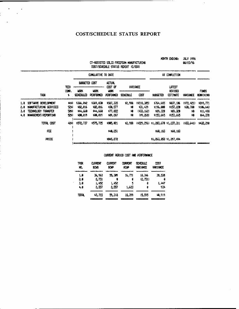
COST/SCHEDULE STATUS REPORT
CT-flSSISTED SOLID FREEFORM MflNUFflCTURING COST/SCHEDULE STATUS REPORT (C/SSR)
MONTH ENDING: JULY 1996 88/15/96
CUMULATIVE TO DATE AT COMPLETION
BUDGETED COST TECH CO». WORK WORK
ACTUAL COST OF WORK
VARIANCE
TASK SCHEDULED PERFORMED PERFORMED SCHEDULE COST
LATEST REVISED FUNDS
BUDGETED ESTIMATE VARIANCE REMAINING
1.0 SOFTWARE DEVELOPMENT 2.8 MANUFACTURING SERVICES 3.8 TECHNOLOGY TRANSFER 4.8 MANAGEMENT/REPORTING
TOTAL COST
FEE
PRICE
44*1 $366,842 $369,838 »587,335 52*1 (82,816 «82,816 $58,577 SKI $44,668 $44,668 $77,822 52*1 $88,819 $88,819 $89,287
$2,988 ($218,385) $764,685 $837,186 ($72,421) $249,771 $8 $31,439 $196,888 $157,228 (38,788 $186,643 $8 ($33,162) $89,328 $89,328 $8 $11,498 $8 ($9,268) $153,665 $153,665 (8 (64,378
48*1 (572,737 (575,725 (885,821 I I (48,251 I I (845,272
(2,988 ((229,296) (1,283,678 (1,237,311 ($33,641) (432,298
(68,183 $68,183
$1,263,853 $1,297,494
TOTAL
CURRENT PERIOD COST AND PERFORMANCE
TASK CURRENT CURRENT CURRENT SCHEDULE COST NO. BCUS BCUP ACWP VARIANCE VARIANCE
1.8 36,963 55,389 16,771 18,346 38,538 2.8 2,751 8 8 (2,751) 0 3.8 1,452 1,452 5 8 1,447 4.8 2,557 2,557 1,623 0 934
43,723 59,318 18,399 15,595 48,919

VARIANCE ANALYSIS REPORTS
TASK: Software Development WBS: 1.0
Budgeted Cost of Work
Scheduled
Budgeted Cost of Work
Performed
Actual Cost of Work
Performed
Cumulative Schedule Variance
Cumulative Cost
Variance
Originally Budgeted
Cost
Latest Revised Estimate
$366,042 $369,030 $587,335 $2,988 ($218,305) $764,685 $837,106
CAUSE OF SCHEDULE VARIANCE: Not material (less than 10%).
ANTICIPATED IMPACT OF SCHEDULE VARIANCE ON TASK: None.
PROPOSED CORRECTIVE ACTION: None.
LATEST REVISED SCHEDULE ESTIMATE: No change.
ANTICIPATED IMPACT OF SCHEDULE VARIANCE ON PROGRAM: None.
CAUSE OF COST VARIANCE: Task 1.1 was completed at a cost of $486,056, an increase of $209,869 over the amount originally budgeted for this task. The increase was not due to technical difficulties; rather it was due to the addition of essential unplanned work. The necessity for this extra work emerged as our understanding of the problem developed and the needs of the user became clearer. Despite the fact that the number of subtasks on Task 1.2 has been increased from 4 to 15, the latest revised estimate has been cut to $351,049, a decrease of $137,449 from the original amount budgeted for this effort. This efficiency is due in part to the work done in Task 1.1 to create a solid foundation for future development activities and in part to important synergisms with other programs that were not anticipated at the time of proposal. Thus, the net variance for Task 1 is ($72,421).
ANTICIPATED IMPACT OF COST VARIANCE ON TASK: This task will overrun unless unexpected efficiencies can be achieved.
PROPOSED CORRECTIVE ACTION: Remaining resources will be reallocated from Task 2 and possibly Task 4.
LATEST REVISED COST ESTIMATE: Task 1.2 was rebaselined this quarter to reflect the latest design analysis. The LRE is now $837,106, an increase of $27,368 from last time.
ANTICIPATED IMPACT OF COST VARIANCE ON PROGRAM: The redistribution of Tasks 2 and 4's dollars will lessen the level of effort associated with these secondary tasks but will have no impact on Task 1, the primary technical effort.

VARIANCE ANALYSIS REPORTS (CONTINUED)
TASK: Manufacturing Services WBS: 2.0
Budgeted Cost of Work
Scheduled
Budgeted Cost of Work
Performed
Actual Cost of Work
Performed
Cumulative Schedule Variance
Cumulative Cost
Variance
Originally Budgeted
Cost
Latest Revised Estimate
$82,016 $82,016 $50,577 $0 $31,439 $196,000 $157,220
CAUSE OF SCHEDULE VARIANCE: Not applicable; level of effort.
ANTICIPATED IMPACT OF SCHEDULE VARIANCE ON TASK: None. This task is not on
any critical path.
PROPOSED CORRECTIVE ACTION: None.
LATEST REVISED SCHEDULE ESTIMATE: No change from last time.
ANTICIPATED IMPACT OF SCHEDULE VARIANCE ON PROGRAM: None.
CAUSE OF COST VARIANCE: Level of effort to date has been less than originally anticipated based on a straight-line projection of the budget allocated for this task. To date, only one part (the Harrier vane) has been reverse engineered.
ANTICIPATED IMPACT OF COST VARIANCE ON TASK: None.
PROPOSED CORRECTIVE ACTION: None.
LATEST REVISED COST ESTIMATE: No change from last time.
ANTICIPATED IMPACT OF COST VARIANCE ON PROGRAM: Unless efficiencies can be
achieved on other tasks, the positive variance will be needed to cover overruns elsewhere in
the program. It may even be necessary to reallocate some of the funds remaining.

VARIANCE ANALYSIS REPORTS (CONTINUED)
TASK: Technology Transition WBS: 3.0
Budgeted Cost of Work
Scheduled
Budgeted Cost of Work
Performed
Actual Cost of Work
Performed
Cumulative Schedule Variance
Cumulative Cost
Variance
Originally Budgeted
Cost
Latest Revised Estimate
$44,660 $44,660 $77,822 $0 ($33,162) $89,320 $89,320
CAUSE OF SCHEDULE VARIANCE: Not applicable; level of effort.
ANTICIPATED IMPACT OF SCHEDULE VARIANCE ON TASK: None. This task is not on
any critical path.
PROPOSED CORRECTIVE ACTION: None.
LATEST REVISED SCHEDULE ESTIMATE: No change from original.
ANTICIPATED IMPACT OF SCHEDULE VARIANCE ON PROGRAM: None.
CAUSE OF COST VARIANCE: Level of effort to date has been more than originally anticipated
based on a straight-line projection of the budget for this task. Costs had been running close
to forecast, but the cost of setting up the first beta site this quarter was much greater than
expected.
ANTICIPATED IMPACT OF COST VARIANCE ON TASK: Funds remaining (see C/SSR) may
not be enough to complete everything we would like to do under this task.
PROPOSED CORRECTIVE ACTION: If necessary, funds will be reallocated to this task from
Task 2.
LATEST REVISED COST ESTIMATE: No change at this time.
ANTICIPATED IMPACT OF COST VARIANCE ON PROGRAM: This level-of-effort task is
secondary to the primary technical effort (Task 1). The only impact of the overrun will be
to limit the number of technology transfer activities performed.

VARIANCE ANALYSIS REPORTS (CONTINUED)
TASK: Program Management WBS: 4.0
Budgeted Cost of Work
Scheduled
Budgeted Cost of Work
Performed
Actual Cost of Work
Performed
Cumulative Schedule Variance
Cumulative Cost
Variance
Originally Budgeted
Cost
Latest Revised Estimate
$80,019 $80,019 $89,287 $0 ($9,268) $153,665 $153,665
CAUSE OF SCHEDULE VARIANCE: Not applicable; level of effort.
ANTICIPATED IMPACT OF SCHEDULE VARIANCE ON TASK:
PROPOSED CORRECnVE ACTION:
LATEST REVISED SCHEDULE ESTIMATE:
ANTICIPATED IMPACT OF SCHEDULE VARIANCE ON PROGRAM:
CAUSE OF COST VARIANCE: Management costs have been more than anticipated from straight-
line projections.
ANTICIPATED IMPACT OF COST VARIANCE ON TASK: None. The variance is expect to
correct itself with time.
PROPOSED CORRECTIVE ACTION: None.
LATEST REVISED COST ESTIMATE: No change from last time.
ANTICIPATED IMPACT OF COST VARIANCE ON PROGRAM: None.