Čáslavská 234 hph ltd
TRANSCRIPT
FFLLIIGGHHTT MMAANNUUAALL
FFOORR TTHHEE SSAAIILLPPLLAANNEE
ČČáássllaavvsskkáá 223344 228844 0011 KKuuttnnáá HHoorraa CCZZEECCHH RREEPPUUBBLLIICC tteell :: ++442200 332277 551122663333 tteell ..//ffaaxx:: ++442200 332277 551133444411 [email protected]
HPH Ltd.

Document No.: G304S/AFM
Date of Issue: 08/14
FFLLIIGGHHTT MMAANNUUAALL FFOORR TTHHEE SSAAIILLPPLLAANNEE
MMooddeell :: Glasflügel 304 S
SSeerriiaall NNoo..::
RReeggiissttrraatt iioonn::
Type Certificate No.:
Date of Issue: 08/14
Pages identified by “Appr” are approved by EASA:
Signature: ..................................................
Authority: ..................................................
Stamp:
Original date of approval: ..................................................
Approved under Ref. No.: ..................................................
This sailplane is to be operated in compliance with information and limitations contained herein. This Flight Manual must be located aboard the sailp lane at all times.
ČČáássllaavvsskkáá 223344 228844 0011 KKuuttnnáá HHoorraa CCZZEECCHH RREEPPUUBBLLIICC tteell :: ++442200 332277 551122663333 ffaaxx:: ++442200 332277 551133444411 iinnffoo@@hhpphh..cczz
HPH Ltd.
FFll iigghhtt MMaannuuaall ffoorr tthhee ssaaii llppllaannee
Document No.: G304S/AFM
Date of Issue: 08/14
0 -1
H P H Ltd.
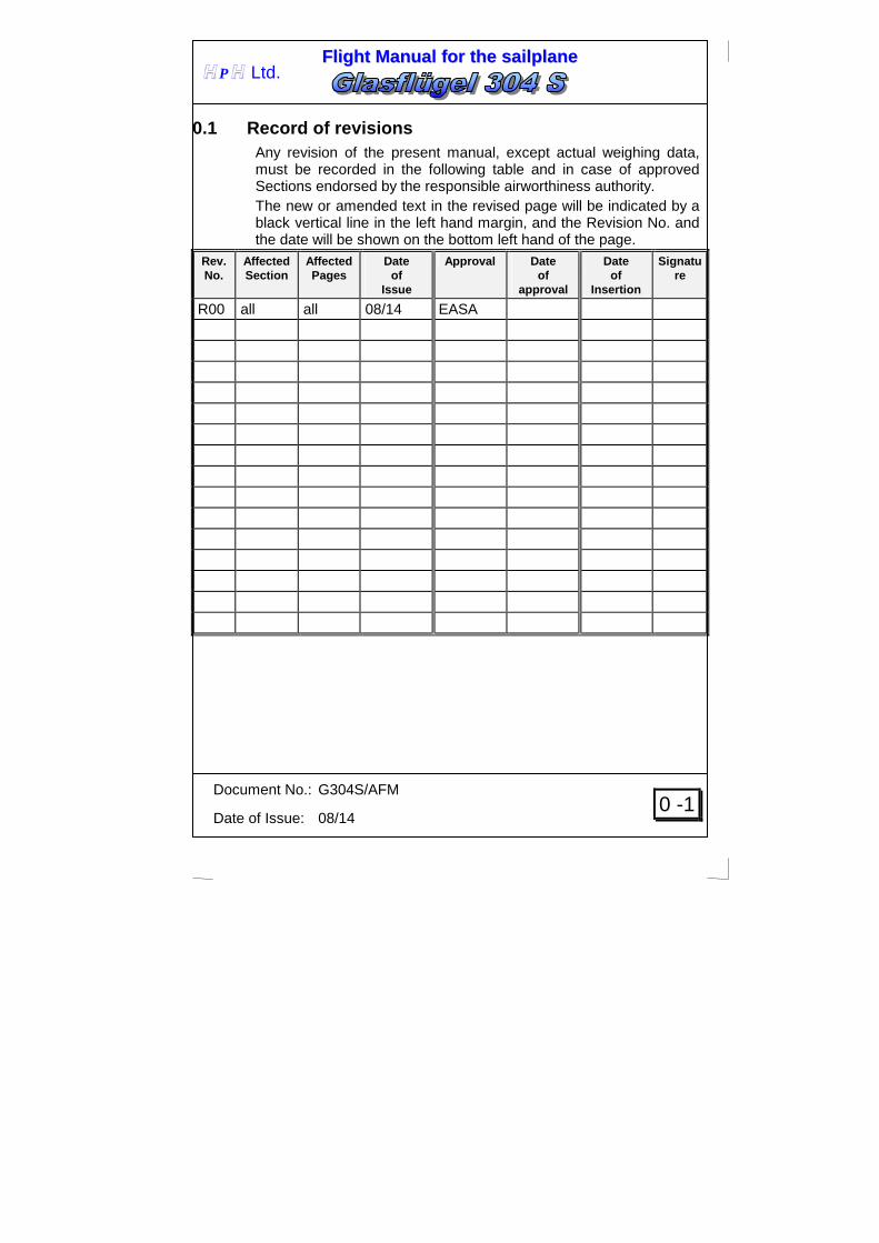
0.1 Record of revisions Any revision of the present manual, except actual weighing data, must be recorded in the following table and in case of approved Sections endorsed by the responsible airworthiness authority. The new or amended text in the revised page will be indicated by a black vertical line in the left hand margin, and the Revision No. and the date will be shown on the bottom left hand of the page.
Rev. No.
Affected Section
Affected Pages
Date of
Issue
Approval Date of
approval
Date of
Insertion
Signature
R00 all all 08/14 EASA

FFll iigghhtt MMaannuuaall ffoorr tthhee ssaaii llppllaannee
Document No.: G304S/AFM
Date of Issue: 08/14
0 -2
H P H Ltd.
0.2 List of Effective Pages Section Page
Date of Issue
Section Page
Date of Issue
2-9 Appr. 08/14
0-1 08/14 2-10 Appr. 08/14
0-2 08/14 2-11 Appr. 08/14
0-3 08/14
0-4 08/14
3 3-1 Appr. 08/14
1 1-0 08/14 3-2 Appr. 08/14
1-1 08/14
1-2 08/14
1-3 08/14 4 4-0 Appr. 08/14
1-4 08/14 4-1 Appr. 08/14
1-5 08/14 4-2 Appr. 08/14
1-6 08/14 4-3 Appr. 08/14
4-4 Appr. 08/14
4-5 Appr. 08/14
4-6 Appr. 08/14
2 2-0 Appr. 08/14 4-7 Appr. 08/14
2-1 Appr. 08/14 4-8 Appr. 08/14
2-2 Appr. 08/14 4-9 Appr. 08/14
2-3 Appr. 08/14 4-10 Appr. 08/14
2-4 Appr. 08/14 4-11 Appr. 08/14
2-5 Appr. 08/14 4-12 Appr. 08/14
2-6 Appr. 08/14 4-13 Appr. 08/14
2-7 Appr. 08/14 4-14 Appr. 08/14
2-8 Appr. 08/14 4-15 Appr. 08/14
FFll iigghhtt MMaannuuaall ffoorr tthhee ssaaii llppllaannee
Document No.: G304S/AFM
Date of Issue: 08/14
0 -3
H P H Ltd.
Section Page
Date of Issue
Section Page
Date of Issue
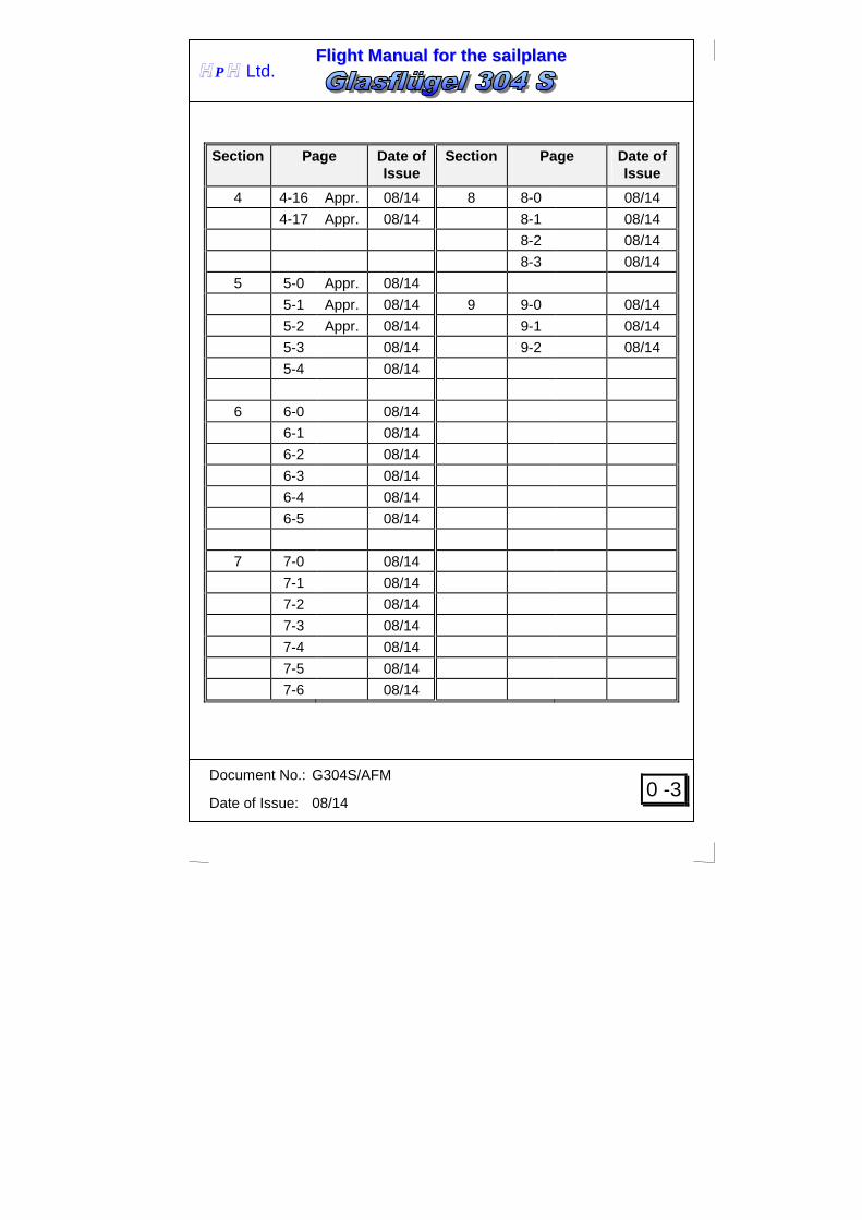
4 4-16 Appr. 08/14 8 8-0 08/14
4-17 Appr. 08/14 8-1 08/14
8-2 08/14
8-3 08/14
5 5-0 Appr. 08/14
5-1 Appr. 08/14 9 9-0 08/14
5-2 Appr. 08/14 9-1 08/14
5-3 08/14 9-2 08/14
5-4 08/14
6 6-0 08/14
6-1 08/14
6-2 08/14
6-3 08/14
6-4 08/14
6-5 08/14
7 7-0 08/14
7-1 08/14
7-2 08/14
7-3 08/14
7-4 08/14
7-5 08/14
7-6 08/14

FFll iigghhtt MMaannuuaall ffoorr tthhee ssaaii llppllaannee
Document No.: G304S/AFM
Date of Issue: 08/14
0 -4
H P H Ltd.
0.3 Table of Contents Section
General .................................................................................... 1 (a non-approved section)
Limitations .............................................................................. 2 (an approved section)
Emergency procedures ......................................................... 3 (an approved section)
Normal procedures ................................................................ 4 (an approved section)
Performance ........................................................................... 5 (a partly approved section)
Weight and balance / equipment list .................................... 6 (a non-approved section)
Sailplane and systems description ...................................... 7 (a non-approved section)
Sailplane handling, care and maintenance ......................... 8 (a non-approved section)
Supplements ........................................................................... 9

FFll iigghhtt MMaannuuaall ffoorr tthhee ssaaii llppllaannee
Document No.: G304S/AFM
Date of Issue: 08/14
1-0
H P H Ltd.
SECTION 1
1. General 1.1 Introduction
1.2 Certification basis
1.3 Warnings, cautions and notes
1.4 Descriptive data
1.5 Three-view drawing

FFll iigghhtt MMaannuuaall ffoorr tthhee ssaaii llppllaannee
Document No.: G304S/AFM
Date of Issue: 08/14
1-1
H P H Ltd.
1.1 Introduction The sailplane flight manual has been prepared to provide pilots with information for the safe and efficient operation of the Glasflügel 304 S sailplane. This manual includes the material required to be furnished to the pilot by JAR-22. It also contains supplemental data supplied by the sailplane manufacturer.
1.2 Certification basis This type of sailplane has been approved by EASA in accordance with JAR-22, Amendement 7, 1st September, 2003 Type Certificate No.: Issued on: Category of airworthiness: utility

FFll iigghhtt MMaannuuaall ffoorr tthhee ssaaii llppllaannee
Document No.: G304S/AFM
Date of Issue: 08/14
1-2
H P H Ltd.
1.3 Warnings, cautions and notes The following definitions apply to warnings, cautions and notes in the flight manual.
WARNING
Means that the non-observation of the corresponding procedure leads to an immediate or important degradation of the flight safety.
CAUTION
Means that the non-observation of the corresponding procedure leads to a minor or to a more or less long term degradation of the flight safety.
NOTE
Draws the attention of any special item not directly related to safety but which is important or unusual.

FFll iigghhtt MMaannuuaall ffoorr tthhee ssaaii llppllaannee
Document No.: G304S/AFM
Date of Issue: 08/14
1-3
H P H Ltd.
1.4 Descriptive data Glasflügel 304 S is single seat 18m flapped sailplane of 18m
FAI class, constructed from fiber reinforced plastics (FRP), featuring camber-changing flaps and a T-tail (with fixed horizontal stabilizer and elevator)
Sailplane description
Fuselage
The fuselage shell is pure CFRP shell construction reinforced with Carbon Aramid hybrid fabrics in the pilot area, therefore capable of large energy absorption. The fuselage tapers behind the wing, the faired-in one piece canopy is hinged forward. Canopy jettison mechanism incorporates the Rögger pivot hook. The pilot is seated in a semi-reclining position. The landing gear is retractable and damped. A C.G. release is fitted as standard, and an Aerotow nose release can be fitted on request. Fuselage is equipped with engine compartment for further propulsion unit installation. Wing The four-piece wing is cantilever and double trapezoidal. Removable wing extensions are optional. It is constructed as a CFRP-Foam-Sandwich shell with extruded spar caps of parallel carbon fibers and shear webs of reinforced GFRP-Foam-Sandwich. Airbrakes are of the Schempp-Hirth type. Two integral water ballast tanks carry a total of 194 liters. Horizontal Tail Unit The horizontal tailplane has a stabilizer and elevators. Trimming is by means of a spring on the control drive. The stabilizer is of GFRP-Foam-Sandwich construction. Fin and Rudder The fin is similar to the stabilizer of GFRP-Foam-Sandwich Shell construction. The rudder is of the CFRP construction.
FFll iigghhtt MMaannuuaall ffoorr tthhee ssaaii llppllaannee
Document No.: G304S/AFM
Date of Issue: 08/14
1-4
H P H Ltd.
Cockpit interior Back-rest and rudder pedals are adjustable in flight. The back-rest rotation point can only be adjusted on the ground. When the canopy is opened the instrument carrier pivots upward and renders possible a comfortable and unrestricted pilot entry and exit. The canopy is ventilated by slots in the canopy frame, fresh air for the pilot is provided by an outlet right of the canopy frame. If necessary the sliding window (DV) in the canopy may be used for ventilation, too. Battery box, barograph tray and a water ballast system are installed.

FFll iigghhtt MMaannuuaall ffoorr tthhee ssaaii llppllaannee
Document No.: G304S/AFM
Date of Issue: 08/14
1-5
H P H Ltd.
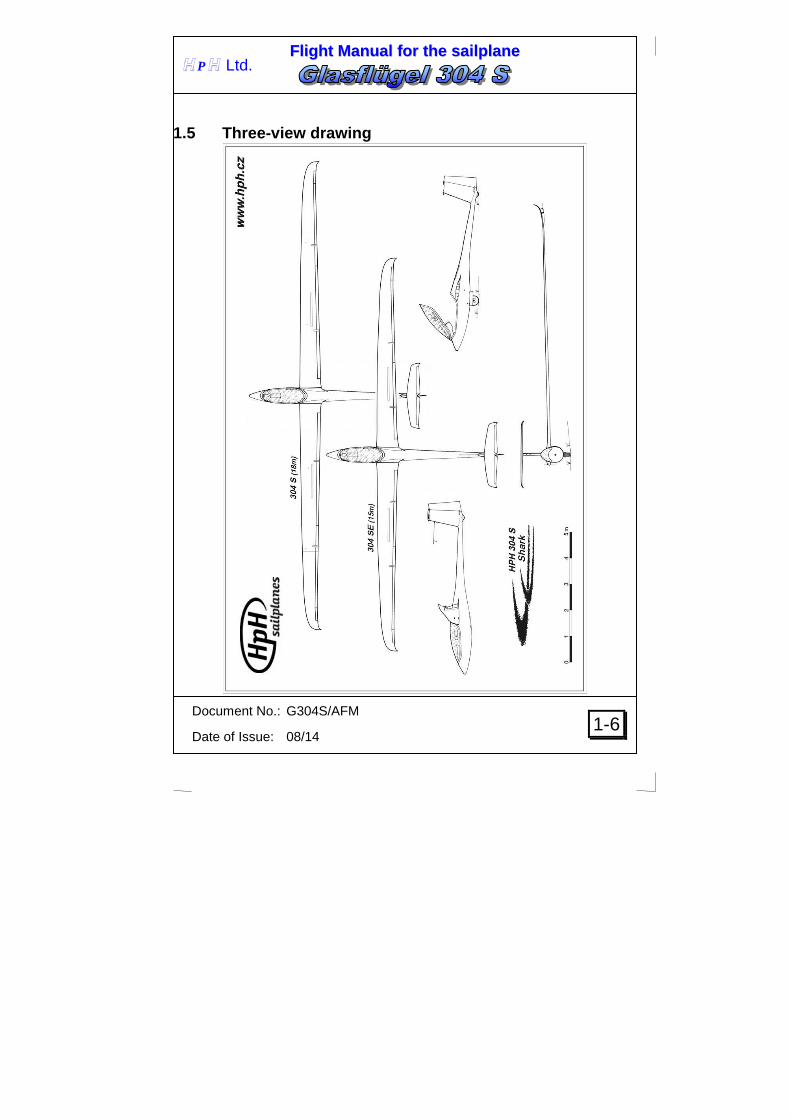
Basic Technical Data Wing Span ................................. 18 m .................. 59.06 ft Wing area ...................... 11.8 m2 .............. 127.01 ft2
Aspect ratio ................. 27.43
Fuselage Length............................ 6.79 m .................. 22.28 ft Width ............................. 0.62 m .................... 2.03 ft Height ............................ 1.48 m .................... 4.86 ft Cockpit height ................ 0.83 m .................... 2.72 ft
Horizontal Tail Unit Span ................................ 2.5 m .................... 6.89 ft Area ............................... 0.99 m2 ................ 10.66 ft2 Aspect ratio ................... 6.33
Vertical Tail Unit Height ............................ 1.25 m .................... 3.77 ft Area ............................... 1.05 m2 .................. 9.58 ft2 Aspect ratio ................... 1.52
Landing gear Main wheel ........................ 5,00x5 Tail wheel ......................... 210x65
FFll iigghhtt MMaannuuaall ffoorr tthhee ssaaii llppllaannee
Document No.: G304S/AFM
Date of Issue: 08/14
1-6
H P H Ltd.
1.5 Three-view drawing

FFll iigghhtt MMaannuuaall ffoorr tthhee ssaaii llppllaannee
Document No.: G304S/AFM
Date of Issue: 08/14
2-0 Approved
H P H Ltd.
SECTION 2
2. Limitations 2.1 Introduction
2.2 Airspeed
2.3 Airspeed indicator markings
2.4 Weight
2.5 Center of Gravity
2.6 Approved maneuvers
2.7 Maneuvering load factors
2.8 Flight crew
2.9 Kinds of operation
2.10 Minimum equipment
2.11 Aerotow
2.12 Other limitations
2.13 Limitations placards

FFll iigghhtt MMaannuuaall ffoorr tthhee ssaaii llppllaannee
Document No.: G304S/AFM
Date of Issue: 08/14
2-1 Approved
H P H Ltd.
2.1 Introduction Section 2 includes operating limitations, instrument markings, and basic placards necessary for safe operation of the sailplane, standard systems and standard equipment. The limitations included in this section and in Section 9. have been approved by the EASA.
2.2 Airspeed Airspeed limitations and their operational significance are shown below:
Speed IAS [km/h]
KIAS IAS [mph]
Remarks
VNE Never exceed speed 260 140 161
Do not exceed this speed in any operation and do not use more than 1/3 of control deflection
VRA Rough air speed 200 107 124
Do not exceed this speed except in smooth air, and then only with caution. Examples of rough air are lee-wave rotor, thunderclouds etc.
VA Maneuvering speed 200 107 124
Do not make full or abrupt control movement above this speed, because under certain conditions the sailplane may be overstressed by full control movement.
VFE Maximum
speed with flaps
+1,+2
L
200
160
107
86
124
99
Do not exceed this speeds in any operation and do not use more than 1/3 of control deflection with flaps set on +1, +2, L
VT Maximum aerotowing speed
150 80 93 Do not exceed this speed during aerotowing
VW Maximum winch-launching speed
130 70 80 Do not exceed this speed during aerotowing

FFll iigghhtt MMaannuuaall ffoorr tthhee ssaaii llppllaannee
Document No.: G304S/AFM
Date of Issue: 08/14
2-2 Approved
H P H Ltd.
CAUTION Keep in mind, that a difference between Indicated Air Speed (IAS) shown by your airspeed indicator and True Air Speed (TAS) is increasing with an altitude increase. This has no influence on the sailplane strength or load, however due to flutter safety the IAS limits shown in table below must not be exceeded in given altitudes.
Altitude Never exceed speed vNE IAS
[m ISA] [ft ISA] [km/h] KIAS [mph]
0
1000
0
3281
260
260
140
140
161
161
2000
3000
4000
5000
6000
7000
8000
9000
10000
6562
9843
13123
16404
19685
22966
26247
29528
32808
260
260
260
248
234
221
209
197
185
140
140
140
133
126
119
112
106
99
161
161
161
154
145
137
129
122
114

FFll iigghhtt MMaannuuaall ffoorr tthhee ssaaii llppllaannee
Document No.: G304S/AFM
Date of Issue: 08/14
2-3 Approved
H P H Ltd.
2.3 Airspeed indicator markings Airspeed indicator markings and their color-code significance are shown below:
Marking Value or range IAS Significance [km/h] KIAS [mph]
White Arc
85 - 200 45 - 107 52 - 124
Allowed range for Flaps set to positive position L – white mark and letter at 160 km/h +1, +2 – white mark and letters at 200 km/h
Green arc
94-200 50-107 58-124 Normal operating range
Yellow arc 200-260 107-140 124-161
Maneuvers must be conducted with caution and only in smooth air
Red line
260 140 161
Maximum speed for all operation.
Yellow triangle
94 50 58
Approach speed at maximum weight without water ballast
2.4 Weight Max. take-off weight ................................... 600 kg 1322 lbs Max. landing weight .................................... 600 kg 1322 lbs Max. weight of all non-lifting parts .............. 373 kg 822 lbs (i.e. all parts incl. cockpit and baggage compartment load, with water ballast inside the fuselage, trim ballast, stabilizator & elevator) Maximum weight in baggage compartment . 10 kg 22 lbs (incl. all installed equipment)
FFll iigghhtt MMaannuuaall ffoorr tthhee ssaaii llppllaannee
Document No.: G304S/AFM
Date of Issue: 08/14
2-4 Approved
H P H Ltd.
CAUTION
Check the weight of non-lifting parts before each flight The maximum baggage weight is 10 kg, 22 lbs including installed equipment and must be considered when establishing the maximum weight of non-lifting parts according to the table above.
CAUTION The outboard wing tanks must be filled in advance.
2.5 Center of Gravity Permitted C.G. range in flight .............................. 25-44,7 %MAC i.e. ....................................................................... 251-387 mm behind a reference point – point on the leading edge of the wing root section at y=425 mm (16.7 in) out of the fuselage center line. Empty sailplane C.G. position for the cockpit load within 70-110 kg (154-242 lbs) must fit into the crosshatched area in the following diagram. If the pilot with a parachute does not reach the placarded minimum cockpit load, the appropriate amount of lead ballast must be carried in the nose. One kg of lead ballast (2.2 lbs) in the ballast box will compensate for 3.49 kg (7 lbs) of the pilot‘s insufficient weight. Maximum lead ballast capacity of the ballast box is 12 kg (26 lbs). Suitable lead ballast plates are available from HPH Ltd. . Permanent tail water ballast allows to pilot maintain the flight cg position at optimum range. 1 kg (2.2 lbs) of the water ballast will compensate for 4.8 kg (10 lbs) of the pilot‘s increased weight. Pilot must check the minimum weight limitation given in ch. 6.3 before use of this trim ballast The empty sailplane C.G. may fit in some cases above or below the crosshatched area of the diagram and the maximum cockpit load is less than 110 kg (242 lbs) or minimum cockpit load is higher than 70 kg (154 lbs). In such case the modification should be approved, at first, as well as recorded in the appropriate documents.

FFll iigghhtt MMaannuuaall ffoorr tthhee ssaaii llppllaannee
Document No.: G304S/AFM
Date of Issue: 08/14
2-5 Approved
H P H Ltd.
TRIM PLAN
G304S
400
450
500
550
600
650
700
250 270 290 310 330 350 370
SAILPLANE EMPTY WEIGHT
[ Kg ]
EM
PT
Y C
G P
OS
ITIO
N
[ m
m ] NORMAL
RANGE
max. 110 kg
min. 70 kg
min. 75 kg
min. 80 kg
min. 85 kg
min. 90 kg

FFll iigghhtt MMaannuuaall ffoorr tthhee ssaaii llppllaannee
Document No.: G304S/AFM
Date of Issue: 08/14
2-6 Approved
H P H Ltd.
2.6 Approved maneuvers This sailplane is certified in the UTILITY category. Intentional aerobatic maneuvers are prohibited.
WARNING Aerobatic maneuvers and intentional spins are prohi bited.
2.7 Maneuvering load factors The following load factors may not be exceeded during maneuvers: n = +5.3 at air speed VA = 200 km/h, 107 KIAS, 124 mph
-2.65 air brakes retracted n = +4.0 at air speed VNE = 260 km/h, 140 KIAS, 161 mph
-1.5 air brakes retracted n = +2 air brakes extended
FFll iigghhtt MMaannuuaall ffoorr tthhee ssaaii llppllaannee
Document No.: G304S/AFM
Date of Issue: 08/14
2-7 Approved
H P H Ltd.
2.8 Flight crew Number of seats ................................ 1 Minimum cockpit load ................. 70 kg 154 lbs Maximum cockpit load .............. 110 kg 242 lbs
WARNING Check the permanent tail water ballast trim before flight. Exceeding the limitation could cause exceeding of the approved aft cg position and could adversely affect sailplane maneuverability and stability. See ch. 2.5
WARNING If the weight of pilot with parachute does not reach the minimum cockpit load placarded, than appropriate amount of lead ballast must be installed. See ch. 2.5
2.9 Kinds of operation There are permitted day VFR flights only.
WARNING Intentional cloud flights are PROHIBITED.
2.10 Minimum equipment The instruments as well as the appropriate parts of the minimum equipment must be of an approved type. Minimum equipment • 1 Airspeed indicator (color marked as in par.2.3.) • 1 Altimeter • 1 Outside air temperature indicator (OAT) with sensor (when
flying with water ballast) • 1 set of four-point safety harness • 1 automatic or manual parachute, otherwise back-cushion
(compressed approx. 39,3 inch / 10cm thick)
FFll iigghhtt MMaannuuaall ffoorr tthhee ssaaii llppllaannee
Document No.: G304S/AFM
Date of Issue: 08/14
2-8 Approved
H P H Ltd.
• 1 Sailplane Flight Manual • Limitation placards in the cockpit
2.11 Aerotow and winch-launching Aerotow The standard sailplane is fitted with the C.G. release for a towing rope. If a nose hook is installed, we recommend to use this one. Maximum aerotowing speed VT.......... 150 km/h, 80 KIAS, 93 mph Maximum rope or weak-ling strength 780 daN For aerotow takeoffs the approved synthetic or natural ropes of 40 m (130 ft.) length may be used. Nevertheless the C.G. hook is approved for aerotow, too. Winch-launch
Only permissible with C.G. tow release in place
Maximum winch-launching speed Vw 130 km/h (70 KIAS, 80 mph)
Weak link in winch cable: .......... max. 780 daN
WARNING Never use the nose release (if installed) for winch-launching takeoff.
2.12 Other limitations No smoking inside the sailplane ! Maximum weight of instrument panel ...... 10 kg ...............22 lbs

FFll iigghhtt MMaannuuaall ffoorr tthhee ssaaii llppllaannee
Document No.: G304S/AFM
Date of Issue: 08/14
2-9 Approved
H P H Ltd.
2.13 Limitations placards

FFll iigghhtt MMaannuuaall ffoorr tthhee ssaaii llppllaannee
Document No.: G304S/AFM
Date of Issue: 08/14
2-10 Approved
H P H Ltd.
WEIGHT LIMITATION
MAX.TAKEOFF WEIGHT 600 kg 1322 lbs
MAX.WEIGHT OF NON-LIFTING PARTS 373 kg 822 lbs
PERMITTED COCKPIT LOAD 70-110 kg 154-242 lbs
FOR COCPIT LOAD LIMITATION REFFER TO ACTUAL WEIGHT AND
BALANCE DATA AT FLIGHT MANUAL SECTION 6
AIRSPEED LIMITATION IAS VNE Never exceed speed
up to 4000 m / 13000 ft 260 km/h 140 KIAS 161 mph VFE Max.SPEED WITH FLAPS
setting +1 +2 200 km/h 107 KIAS 124 mph setting L 160 km/h 86 KIAS 99 mph
AIRSPEED LIMITATION IAS VA Maneuvering speed 200 km/h 107 KIAS 124 mph
VRA Rough air speed 200 km/h 107 KIAS 124 mph
VT Max. aerotowing speed 150 km/h 80 KIAS 93 mph
VW Max. winchlaunch speed 130 km/h 70 KIAS 80 mph
VLO Max. L/G operating speed 180 km/h 96 KIAS 111 mph
AEROBATIC MANOEUVRES, INTENTIONAL SPINS AND
CLOUD FLIGHTS ARE PROHIBITED

FFll iigghhtt MMaannuuaall ffoorr tthhee ssaaii llppllaannee
Document No.: G304S/AFM
Date of Issue: 08/14
2-11 Approved
H P H Ltd.
Altitude Never exceed speed vNE IAS
[m] [ft] [km/h] KIAS [mph]
0
1000
0
3281
260
260
140
140
161
161
2000
3000
4000
5000
6000
7000
8000
9000
10000
6562
9843
13123
16404
19685
22966
26247
29528
32808
260
260
260
248
234
221
209
197
185
140
140
140
133
126
119
112
106
99
161
161
161
154
145
137
129
122
114

FFll iigghhtt MMaannuuaall ffoorr tthhee ssaaii llppllaannee
Document No.: G304S/AFM
Date of Issue: 08/14
3-0 Approved
H P H Ltd.
SECTION 3
3. Emergency procedures 3.1 Introduction
3.2 Canopy jettison
3.3 Bailing out
3.4 Stall recovery
3.5 Spin recovery
3.6 Spiral dive recovery
3.7 Other emergencies 3.7.1 Wingtip catching in high grass during takeoff 3.7.2 Towing rope release at low height 3.7.3 Flying with uneven water ballast
FFll iigghhtt MMaannuuaall ffoorr tthhee ssaaii llppllaannee
Document No.: G304S/AFM
Date of Issue: 08/14
3-1 Approved
H P H Ltd.
3.1 Introduction Section 3 provides checklist and amplified procedures for coping with emergencies that may occur.
3.2 Canopy jettison 1. Grasp (from below) the red grips (right and left of the canopy frame) 2. Pull them back 3. Push the canopy upward.
3.3 Bailing out 1. Direct the sailplane to an uninhabited place 2. Canopy jettison acc. to 3.2 3. Release safety harness and spread them aside 4. Bend you legs under the body 5. Roll over the cockpit frame
WARNING
During bail out try to avoid interfering with the c ontrol stick that might result in non-expected abrupt sailplane motion.
3.4 Stall recovery 1. Push the control stick forward 2. After stall recovery transit to gliding.
3.5 Spin recovery 1. Control stick - ailerons in neutral position 2. Flaps - set 0 3. Rudder pedals - full deflection opposite to the direction of
the spin 4. Control stick - Push the control stick forward
until the rotation stops 5. Neutralize rudder and recover the dive

FFll iigghhtt MMaannuuaall ffoorr tthhee ssaaii llppllaannee
Document No.: G304S/AFM
Date of Issue: 08/14
3-2 Approved
H P H Ltd.
3.6 Spiral dive recovery 1. Balance the bank by coordinate use of rudder and ailerons
controls 2. Recover the dive
3.7 Other emergencies
3.7.1 Wingtip catching in high grass during takeoff Take-Off's from not mowed grass runways should be avoided both for aerotow and winch-launching. Should a wingtip be caught in high grass, release immediately, delaying this may result in a ground loop.
3.7.2 Towing rope release at low height A speed of at least 90 km/h (49kts, 56mph) should be maintained after release at low height in straight and level flight (the speed increases up to 15 % with water ballast!). In a turn the speed should be increased according to the angle of bank. In this manner the unintentional and unnoticed stalled flight will be avoided.
3.7.3 Flying with uneven water ballast If, on dumping water ballast, the wing tanks are emptying unevenly or only on one side – which is recognized at lower speeds by having to apply opposite aileron for normal flying attitude – entering a stall must be avoided. When landing in this condition, the touch down speed must be increased by about 10 km/h (5 kt, 6 mph) and the pilot must be prepared for the sailplane to veer off course as the heavier wing tends to drop somewhat sooner than normal (apply opposite aileron).
3.7.4 Cable chute opening during winch-launching In the early phase of a winch-launching, the cable chute may open if its size is too large or if the climb is too flat. In such case release immediately and land straight ahead.

FFll iigghhtt MMaannuuaall ffoorr tthhee ssaaii llppllaannee
Document No.: G304S/AFM
Date of Issue: 08/14
4-0
H P H Ltd.
Approved
SECTION 4
4. Normal procedures 4.1 Introduction
4.2 Rigging and de-rigging
4.3 Daily inspection
4.4 Preflight inspection
4.5 Normal procedures and recommended speeds 4.5.1 Takeoff and climbing 4.5.2 Flight 4.5.3 Approach and landing 4.5.4 Flying with water ballast 4.5.5 High speed flight 4.5.6 Slow speed flight – stall characteristics 4.5.7 Cloud flying 4.5.8 Flights below zero 4.5.9 Flight in rain 4.5.10 Aerobatics
FFll iigghhtt MMaannuuaall ffoorr tthhee ssaaii llppllaannee
Document No.: G304S/AFM
Date of Issue: 08/14
4-1
H P H Ltd.
Approved
4.1 Introduction Section 4 provides checklist and amplified procedures for the conduct of normal operation. Normal procedures associated with optional systems can be found in section 9.
4.2 Rigging and de-rigging 4.2.1 Rigging 1. Clean and grease pins and bearings. 2. In the cockpit, the flap lever is set at high speed, the brake lever
in the medium position, and the water ballast lever set in the closed position.
3. First rig Port wing, temporarily lock with the main pin by engaging it only into the front spar fork bush. Pay attention that the bellcranks on the root rib are in their neutral position and are actually engaging into the opposing socket fittings on the fuselage.
4. Rig Starboard wing with the same lever settings as Port wing, and pull together with rigging tool. Ensure correct engagement of control as with Port wing.
5. Momentarily remove main wing spar pin. Level main pin bushes by moving wintips up and down. When bushes line up push pin in and lock.
6. Rig both wing extensions. Inset and lock pins of the wingextensions.
7. Check aileron and airbrake functions. 8. Push tailplane onto the rigging - drive pins and pull out front
connection pin with tool, push tailplane L.E. down and push front connection pin fully into position, remove tool. Check that the elevator rigging-drive pins are actually correctly engaged into their opposing elevator fittings (move elevator).
9. Tape off gaps.
FFll iigghhtt MMaannuuaall ffoorr tthhee ssaaii llppllaannee
Document No.: G304S/AFM
Date of Issue: 08/14
4-2
H P H Ltd.
Approved
4.2.2 De-rigging 1. Pull front tailplane connection pin out, with the help of the tool,
and lift up tailplane. 2. Unlock and remove connecting pins of the wingextensions and
apply the hand force to take the wingextension out of the wingtip .
3. Lift wingtips and remove main pin. 4. With the help of the rigging tool, or by pulling on the wingtips,
separate the wings from the fuselage.
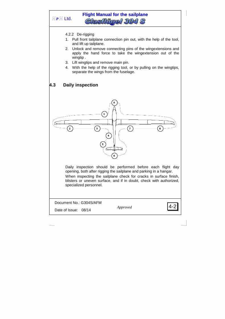
4.3 Daily inspection
Daily inspection should be performed before each flight day opening, both after rigging the sailplane and parking in a hangar. When inspecting the sailplane check for cracks in surface finish, blisters or uneven surface, and if in doubt, check with authorized, specialized personnel.

FFll iigghhtt MMaannuuaall ffoorr tthhee ssaaii llppllaannee
Document No.: G304S/AFM
Date of Issue: 08/14
4-3
H P H Ltd.
Approved
1 a) Open the cockpit, check if the main pin is installed and locked. b) Visual cockpit control inspection. c) Remove foreign material from fuselage. d) Check tire pressure of main wheel
Tire size 5.00-5
Takeoff weight [kg]
Main wheel pressure [kPa]
380 350 450 400 600 500
e) Check function of tow release, condition and spacing of cable deflector plates.
2 a) Check ailerons for full and free movement. b) Check aileron tip rib for damage. c) Check locking of the wingextension. d) Through the lid on the lower shell check the connections of the
aileron and flap control drive mechanism.
3 a) Check air brakes for free movement and close fit. b) With airbrakes opened check the airbrake box for the possible
water accumulation - water should be removed by sponge. c) Check aileron trailing edges for damage.
Lightly shake ailerons on the trailing edge to detect unusually large play in the system.
d) Check hinges for any damage.
4 a) Check if the holes for static pressure on the fuselage shell are clear.
FFll iigghhtt MMaannuuaall ffoorr tthhee ssaaii llppllaannee
Document No.: G304S/AFM
Date of Issue: 08/14
4-4
H P H Ltd.
Approved
5 a) Check if the front stabilizer attachment bolt is engaged. b) Check for blocked Pitot, gently blow into the Pitot to check ASI
function. c) Fit compensatory tube and check line. When blowing against
tube, the connected vertical speed indicator registers "climb". d) Check tire pressure in tail wheel...250 kPa.
6 a) Check elevator and rudder for free and full movement. b) Check elevator and rudder for damage,
lightly shake by hand on trailing edge to check for unusually large play in system.
7 Refer to 3.
8 Refer to 2.
9
Check the function of the nose release mechanism (if installed). After a hard landing, or excessively high "G" loads, the bending frequency of the wings must be checked and the sailplane carefully examined for any indications of damage. Dismantle the sailplane and check surface finish for cracks. Look for white areas (that may indicate delamination) at the wing spar root ends, wing root rib fittings, landing gear attachments, tail fittings, and all areas of concentrated loads. Also inspect the central wing pin and tail attachments for distortion. If damage is found, the sailplane should be grounded until any repairs have been completed.

FFll iigghhtt MMaannuuaall ffoorr tthhee ssaaii llppllaannee
Document No.: G304S/AFM
Date of Issue: 08/14
4-5
H P H Ltd.
Approved
4.4 Preflight inspection 1. Parachute correctly fitted? 2. Safety harness correctly and firmly adjusted? 3. Backrest and pedals locked in comfortable position? 4. All controls and instruments within easy reach? 5. Airbrakes locked? 6. Control check? Free, full and correct movements of controls? 7. Correct trim position? 8. Canopy locked? 9. Release check? 10. Towline on correct release - correct weak-link? 11. Set flaps 12. Set Altimeter!

FFll iigghhtt MMaannuuaall ffoorr tthhee ssaaii llppllaannee
Document No.: G304S/AFM
Date of Issue: 08/14
4-6
H P H Ltd.
Approved
4.5 Normal procedures and recommended speeds
4.5.1 Takeoff and climbing Aerotow Approved ropes made of synthetic and natural fibers with length from 40 m (131ft.) may be used for aerotowing. If a nose hook is installed, we recommend to use this one. Nevertheless the C.G. hook is approved for aerotow, too. When commencing the take-off run, use wheel brake slightly to prevent rolling over tow rope. Before takeoff adjust the trim depending on the cockpit load. The trim should be in neutral position if the sailplane C.G. ranges from forward to medium position. If the C.G. ranges from medium to rear position, then trim "nose heavy". Flap setting during aerotow: “+ 1“. At rear CG positions the control stick should be pushed to lift the tail unit. With rear C.G. position, high take-off weight, or strong cross wind commence the take-off run with flap-setting “– 2” or “-1”, until sufficient aileron control is available. Then move flap setting back to take-off position “+ 1” or “+2” (considerably below lift-off speed, in order to prevent "ballooning"). After lift-off at approx. 80-85 km/h (43-45 KIAS, 49-52 mph) (this speed is increasing up to 15 % with the water ballast) retrim to reduce elevator loads. Normal towing speed .... 100-120 km/h 54-65 KIAS 62-75 mph (this speed is increasing up to 15 % with the water ballast) Max. aerotowing speed ....... 150 km/h 80 KIAS 93 mph At max. AUW and rear CG positions is recommended min. airspeed 125 km/h, 67 KIAS, 77 mph, and at rough air 130 km/h, 70 KIAS, 80 mph.

FFll iigghhtt MMaannuuaall ffoorr tthhee ssaaii llppllaannee
Document No.: G304S/AFM
Date of Issue: 08/14
4-7
H P H Ltd.
Approved
The main landing gear can be retracted during tow. Force required for the landing gear operation is minimized using the gas spring at the mechanism, therefore slide the control lever slowly and continuously. Should the sailplane be unintentionally displaced laterally, it should be cautiously but immediately steered back to normal aerotow position. Should the sailplane be displaced vertically too high, with a danger of over-flying the tow aircraft, the air brakes should be open. Rope release: Pull the release knob several times to be sure, that the rope was released. Winch-launching
WARNING NEVER use the nose release mechanism (if installed) for winch-
launching!
Winch tow must only be attempted on the C.G. release. Before take-off, the trim is set to "normal" for forward and medium C.G. positions, and "nose heavy" for medium to rear C.G. positions. Flap setting for launching: + 1 When commencing the take-off run, use wheel brake slightly to prevent rolling over tow rope. This sailplane shows normal behavior during winch tow and even with rear C.G. positions has only a minor tendency to enter into a steep climb after take-off. Depending on the trim-setting, a correction with the elevator may be necessary to prevent a steep climb in the early take-off phase. After a safety height of approx. 50m (150ft) is reached, the sailplane can be brought into a steeper climb by more back pressure on the control column. If too much back pressure is applied and proposing occurs (elevator stall), release some of the back pressure.

FFll iigghhtt MMaannuuaall ffoorr tthhee ssaaii llppllaannee
Document No.: G304S/AFM
Date of Issue: 08/14
4-8
H P H Ltd.
Approved
Avoid rapid lift-off maneuvers or low towing speeds. The high wing loading of this sailplane requires the pilot to abort the take-off and release, if the towing speed drops below 95 km/h (51 kts, 59 mph) (with water ballast 110 km/h (59 kts, 68 mph)). If possible, use small cable chutes to prevent deploying at flat climb angles. At maximum towing height, the cable will back release automatically, however, you should not neglect to pull the release knob several times.
WARNING The low performance winches with limited engine RPM and other limitations, as well as the takeoff at the tail wind conditions, calm air, filled water tanks etc., require special attention before take-off, to ensure that the winch is providing enough power in reserve to maintain the safe towing speeds.
4.5.2 Flight At a safe altitude, experiment with the air brakes and note loss of height at various speeds. Familiarize yourself with flap operation. Elevator was optimized for dynamic soaring between thermals (dolphining or zooming). Sailplane response to pushing is steeper than to pulling.
TOWING SPEEDS
normal minimum towing speed 105km/h 57kts, 65mph
with water ballast 120km/h 65kts, 75mph
Max. aero towing speed Max. winch towing speed
150km/h 80kts, 93mph 130km/h 70kts, 80mph

FFll iigghhtt MMaannuuaall ffoorr tthhee ssaaii llppllaannee
Document No.: G304S/AFM
Date of Issue: 08/14
4-9
H P H Ltd.
Approved
4.5.3 Approach and landing The normal flap setting for landing is at position “L. The normal approach speed with air brakes fully extended and the extended landing gear is approx. 90 km/h (49 KIAS, 56 mph) at the landing weight of 430 kg (948 lbs). Minimal approach speed is 85 km/h (45 KIAS, 52 mph), although flaring with full airbrake could be difficult. For better aileron control during strong turbulence, the approach can be made with flap setting +2 or +1 at speed between 100 and 110km/h (53-59 KIAS, 62-68 mph). The approach speeds have to be increased of approx. 20% at the landing weight of 600 kg (1322 lbs). The glider should be fully "held-off" in the flare. Failure to do can result in the glider touching down on the main-wheel with the tail-wheel still some distance from the ground. In this case the glider will bounce. This can be prevented by performing a fully held-off flare. Two point touchdown (main and tail wheels) is optimal result of landing flare. Immediately before touch-down, the air brakes should be always open fully. Sideslip is suitable for steep approaches. The sideslip angle increases proportionally to aileron and rudder deflection (aileron deflection depends on rudder deflection in horizontal flight) Ailerons are effective to control approach glide angle and direction even for maximal side rudder deflections.
CAUTION
The water ballast (if filled) should be emptied before landing.
CAUTION
At weight of 600 kg (1323 lbs) and rear CG position, when the side rudder is fully deflected than the rudder suction occurs. This phenomenon decrease the side rudder control force nevertheless the sideslip could be controlled in standard manner and does not require special pilot skills.

FFll iigghhtt MMaannuuaall ffoorr tthhee ssaaii llppllaannee
Document No.: G304S/AFM
Date of Issue: 08/14
4-10
H P H Ltd.
Approved
4.5.4 Flying with water ballast At average climbing speeds of less than 1,5m/sec (2,9kts, 300 ft/min) the use of water ballast does not benefit. This is valid also for flights in tight thermals, which require steep angles of bank.
CAUTION
Do not add water ballast below O°C (32oF), because of freezing danger.
Wing water ballast tanks Wing water ballast tanks are located in front of the main spar of the central wing section. Contamination of the filling water must be avoided. Before water ballast is added, check the table in section 6.4 for the maximum weight of water ballast. The total capacity of the wing tanks is 194 liters (aprox. 42 UKgal, 51 USgal). Let the actuating lever in "close" position, fill through the openings at the upper wing surface.
CAUTION
As the holes in the filler cap also serves for venting the tank, it must always be kept open”
Tanks must not be pressurized, e.g. fill directly from the water hose. Both tanks must be filled equally.
CAUTION The outboard wing tanks must be filled in advance.
Balance both wings prior take-of with semi filled tanks. Your helper should support the wing to prevent wing drop. Water ballast tanks are dumped through the valves at the wing lower surface. Wing valve controls are connected with the fuselage automatically during the sailplane rigging. Before rigging the control lever at the cockpit must be at closed position. Tanks are equipped with ribs to prevent water pouring in the tanks during slips.

FFll iigghhtt MMaannuuaall ffoorr tthhee ssaaii llppllaannee
Document No.: G304S/AFM
Date of Issue: 08/14
4-11
H P H Ltd.
Approved
CAUTION The water ballast should be emptied before landing. It takes about 4 minutes when the tanks were full. During dumping check if the water is dumped simultaneously from both wings. If water is pouring only from one side than stop the dumping.
Permanent tail water ballast tank Permanen t tail water ballast tank is located inside of the fin – above the tail wheel , in front of the fin spar. Contamination of the filling water must be avoided. Before water ballast is added, check the table in section 6.3 for the maximum weight of water ballast. The total capacity of the permanent tail water ballast tank is 4.0 liters (aprox. 0.9 UKgal, 1.0 USgal). Permanent tail water ballast allows to pilot maintain the flight cg position at optimum range . It could be used either for flights with or without wing water ballast. Adding this ballast limits the minimum pilot’s weight. Filling hose is located under the elevator lid on the port side of the side rudder. This filling hose could be connected with the appropriate filling can by tube of max. outer diameter 6 mm (0.234 in.).
CAUTION
Tank must not be pressurized, e.g. fill directly from the water hose.
The tank has six (6) spill holes on the port side, all properly marked from 0 to 4.0l according to the ballast to be filled. The venting of the tank is through the uppermost 4.0 litre hole (which always remains open – even with full tank). The ballast quantity to be filled depends on the pilot seat load (weight of pilot + parachute) – see loading table at section 6.3. Seal all the holes bellow the hole with marking the load to be filled. Example If required load is 4 l, than seal holes marked from 0 to 3 l. All excessive water over 4l will leak through the hole marked 4l.

FFll iigghhtt MMaannuuaall ffoorr tthhee ssaaii llppllaannee
Document No.: G304S/AFM
Date of Issue: 08/14
4-12
H P H Ltd.
Approved
Drainable tail water ballast tank Drainable tail water ballast tank is located inside of the fin – above the permanent tail water ballast tank , in front of the fin spar. Contamination of the filling water must be avoided. Before water ballast is added, check the table in section 6.5 for the maximum weight of water ballast. The total capacity of the permanent tail water ballast tank is 6 liters (aprox. 1.32UKgal, 1.58 USgal). Drainable tail water ballast compensates wing water ballast tank load and allows to pilot maintain the flight cg position at optimum range. It should be used only for flights with wing water ballast. Filling hose is located under the elevator lid on the starboard side of the side rudder. This filling hose could be connected with the appropriate filling can by tube of max. outer diameter 6 mm (0.234 in.).
CAUTION
Tank must not be pressurized, e.g. fill directly from the water hose.
The tank has six (6) spill holes on the port side, all properly marked from 1 to 6 l according to the ballast to be filled. The venting of the tank is through the uppermost 6 litre hole (which always remains open – even with full tank). The ballast quantity to be filled depends on the wing water ballast load – see loading table at section 6.5. Seal all the holes bellow the hole with marking the load to be filled. Both wing tanks and drainable tail tanks are controlled by the same lever. Let the actuating lever in "close" position before filling. The water ballast is dumped through the valve on the bottom of fuselage aft of the fin shear web. It takes about 3 minutes when the tank was full, i.e. tail ballast is dumped faster than wing ballast. Example If required load is 6 l, than seal holes marked from 1 to 5 l. All excessive water over 6l will leak through the hole marked 6l.

FFll iigghhtt MMaannuuaall ffoorr tthhee ssaaii llppllaannee
Document No.: G304S/AFM
Date of Issue: 08/14
4-13
H P H Ltd.
Approved
4.5.5 High speed flight During high speed flight, pay attention to the never exceed speed. Refer to 2.2 and 2.3 for the Airspeed limits and Airspeed Indicator Marking. Aileron and rudder full deflections may be applied up to the Maneuvering speed Full control deflections of aileron and rudder are allowable up to VA=200 km/h IAS (107 KIAS, 124 mph).
Only 1/3 of the aileron and rudder full deflections may be used up to Never exceed speed VNE=260 km/h IAS (140 KIAS, 161 mph).
Elevator deflections must be limited, as well, to not exceed the load factors shown in 2.7. During extreme turbulence, as it may occur for instance in wave rotors, thunderclouds, visible up-currents (stubble fire), or while crossing mountain ranges, the maximum speed in rough air VRA 200 km/h IAS (107 KIAS, 124 mph) should not be exceeded. The necessary control column travel is relatively small from the stalling speed to the maximum speed, in particular at rear C.G. positions; however any speed change will be noticed by a change of the control forces. Elevator has the steeper response on pushing than pulling. The air brakes can be open up to VNE = 260 km/h IAS (140 KIAS, 161 mph), however this should only be done in an emergency or when unintentionally exceeding the maximum permissible speeds shown in 2.2, which is indicated by a sudden deceleration. For this reason, ensure that your harness is tight, and that you do not unintentionally move or jolt the control column while operating the air brake lever. Loose objects in the cockpit should be avoided, as well.
CAUTION
Extension of the airbrakes at airspeed above 170 km/h (91 KIAS, 105 mph) cause their suction, i.e. aerodynamic forces acts in the direction of the extension. Pilot should expect these forces and
must prevent undesirable fast extension.

FFll iigghhtt MMaannuuaall ffoorr tthhee ssaaii llppllaannee
Document No.: G304S/AFM
Date of Issue: 08/14
4-14
H P H Ltd.
Approved
Pay attention also to the fact, that recovery from dives with airbrakes employed, should be more gentle than with airbrakes deployed (see Ch.: 2.7 load factors).
4.5.6 Slow speed flight – stall characteristics For familiarization with Glasflügel 304 S sailplane, we recommend to perform stalling tests from a straight and level flight, and from a turn of 45° bank. The tests should be done of course at a safe altitude. Refer to Section 5. par. 5.2.2 for the sailplane stalling speeds.. Flying without water ballast
With medium and forward C.G. positions you can fly at the minimal steady airspeed with elevator control reaching its stop. The controllability is adequate up to the reach of the longitudinal control rear stop, than, with the elevator fully deflected, the angle of attack cannot be increased no more. The sailplane continues to fly in straight flight with increased rate of descent 4 m/s. This situation shows up by "spongy" controls. Slip and bank could be controlled. A normal flying attitude is regained by releasing the back pressure from the stick.
With aft cg position stall warning usually occurs 5 km/h (3-5 KIAS, 3-6 mph) above stalling speed. Stall warning is vibration of the sailplane and could be easily recognized. If the stick is pulled further back, these effects become more pronounced. After reaching the stalling speed the sailplane tends to drop the nose.
If the stick is eased firmly forward than the stall is terminated and sailplane continues at normal flight attitude. Loss of the height during the stall is 30-35 m. If the airbrakes are extended than the loss is 50 m.
FFll iigghhtt MMaannuuaall ffoorr tthhee ssaaii llppllaannee
Document No.: G304S/AFM
Date of Issue: 08/14
4-15
H P H Ltd.
Approved
Flying with water ballast, AUW = 600 kg
With medium and forward C.G. positions you can fly at the minimal steady airspeed with elevator control reaching its stop. The controllability is adequate up to the reach of the longitudinal control rear stop, than, with the elevator fully deflected, the angle of attack cannot be increased no more. The sailplane continues to fly in straight flight with increased rate of descent. This situation shows up by "spongy" controls. Slip and bank could be controlled.
If the stick is eased firmly forward than the stall is terminated and sailplane continues at normal flight attitude. Loss of the height during the stall is 30-35 m. If the airbrakes are extended than the loss is 50 m.
Sideslip of 5~ 10° has no influence to the above described behavior.

FFll iigghhtt MMaannuuaall ffoorr tthhee ssaaii llppllaannee
Document No.: G304S/AFM
Date of Issue: 08/14
4-16
H P H Ltd.
Approved
4.5.7 Cloud flying Cloud flying is prohibited.
4.5.8 High altitude flight
CAUTION Keep in mind, that a difference between Indicated Air Speed (IAS) shown by your airspeed indicator and True Air Speed (TAS) is increasing with an altitude increase. This has no influence on the sailplane strength or load, however due to flutter safety the IAS limits shown in table below must not be exceeded in given altitudes.
Altitude Never exceed speed vNE IAS
[m ISA] [ft ISA] [km/h] KIAS [mph]
0
1000
0
3281
260
260
140
140
161
161
2000
3000
4000
5000
6000
7000
8000
9000
10000
6562
9843
13123
16404
19685
22966
26247
29528
32808
260
260
260
248
234
221
209
197
185
140
140
140
133
126
119
112
106
99
161
161
161
154
145
137
129
122
114
4.5.9 Flights below zero The control system friction may increase when the temperature is below zero degrees of Centigrade, as well as during winter flying. Ensure that all control elements are free of moisture to prevent freezing. This, in particular, applies to the AIR BRAKES.

FFll iigghhtt MMaannuuaall ffoorr tthhee ssaaii llppllaannee
Document No.: G304S/AFM
Date of Issue: 08/14
4-17
H P H Ltd.
Approved
Continuously operate controls and air brakes at short intervals. During flights with water ballast, note the recommendation under 4.5.4.
4.5.10 Flight in rain Intentional take of at rain is prohibited, because the rain influence on the flight performance was not certified. Nevertheless no degradation of the flight behavior requiring special pilot skills during unintentional flight at rain was reported.
4.5.11 Aerobatics Aerobatic maneuvers are prohibited.
FFll iigghhtt MMaannuuaall ffoorr tthhee ssaaii llppllaannee
Document No.: G304S/AFM
Date of Issue: 08/14
5-0
H P H Ltd.
SECTION 5
5. Performance 5.1 Introduction
5.2 Approved data 5.2.1 Airspeed indicator system calibration 5.2.2 Stall speeds
5.3 Non-approved further information 5.3.1 Speed polar 5.3.2 Demonstrated crosswind performance
Approved
FFll iigghhtt MMaannuuaall ffoorr tthhee ssaaii llppllaannee
Document No.: G304S/AFM
Date of Issue: 08/14
5-1
H P H Ltd.
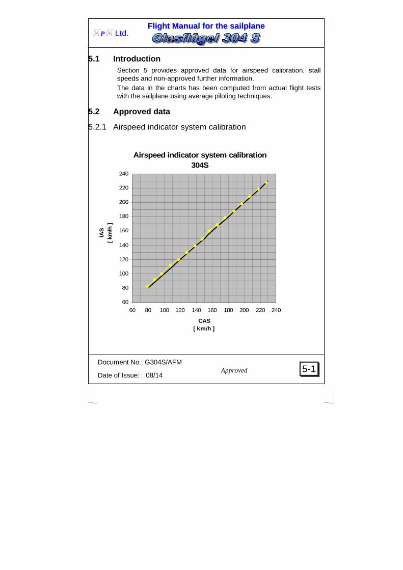
5.1 Introduction Section 5 provides approved data for airspeed calibration, stall speeds and non-approved further information. The data in the charts has been computed from actual flight tests with the sailplane using average piloting techniques.
5.2 Approved data
5.2.1 Airspeed indicator system calibration
Airspeed indicator system calibration 304S
60
80
100
120
140
160
180
200
220
240
60 80 100 120 140 160 180 200 220 240
CAS[ km/h ]
IAS
[ km
/h ]
Approved

FFll iigghhtt MMaannuuaall ffoorr tthhee ssaaii llppllaannee
Document No.: G304S/AFM
Date of Issue: 08/14
5-2
H P H Ltd.
5.2.2 Stall speeds Air brakes Flaps Takeoff Weight
CG position (% MAC)
464 kg
1023 lbs
21%
420 kg
926 lbs
34%
427 kg
941 lbs
46,4%
Retracted
“L”
75 km/h
40.4 KIAS
46.6 mph
65 km/h
35 KIAS
40.3mph
66 km/h
35.6 KIAS
41 mph
“0”
83 km/h
44.8 KIAS
51.5 mph
69 km/h
37.2 KIAS
42.8 mph
64 km/h
34.5 KIAS
39.7 mph
“-2”
88 km/h
47.5 KIAS
54.6 mph
78 km/h
42.1 KIAS
48.4 mph
70 km/h
37.7 KIAS
43.4 mph
Extended
“L”
80 km/h
43.1 KIAS
49.7 mph
70 km/h
37.7 KIAS
43.4 mph
72 km/h
38.8 KIAS
44.7 mph
Air brakes Flaps Takeoff Weight
CG position (% MAC)
600 kg
1323 lbs
27%
594 kg
1309 lbs
37%
600 kg
1323 lbs
46,5%
Retracted
“L”
78 km/h
42.1 KIAS
48.4 mph
78 km/h
42.1 KIAS
48.4 mph
77 km/h
41.5 KIAS
47.8 mph
“0”
92 km/h
49.6 KIAS
57.1 mph
91 km/h
49.1 KIAS
56.5 mph
88 km/h
47.5 KIAS
54.6 mph
“-2”
98 km/h
52.9 KIAS
60.8 mph
97 km/h
52.3 KIAS
60.2 mph
96 km/h
51.8 KIAS
59.6 mph
Extended
“L”
85 km/h
45.8 KIAS
52.8 mph
84 km/h
45.3 KIAS
52.1 mph
82 km/h
44.2 KIAS
50.9 mph
Approved

FFll iigghhtt MMaannuuaall ffoorr tthhee ssaaii llppllaannee
Document No.: G304S/AFM
Date of Issue: 08/14
5-3
H P H Ltd.
Speed polarGlasflugel 304S - 18 m
-3.50
-3.00
-2.50
-2.00
-1.50
-1.00
-0.50
0.00
50 60 70 80 90 100 110 120 130 140 150 160 170 180 190 200
TAS ( km/h )
Ws
( m/s
)
m/S = 31.3 kg/m2m = 370 kg
m/S = 50.8 kg/m2m = 600 kg
5.3 Non-approved further information
5.3.1 Speed polar Computed data
FFll iigghhtt MMaannuuaall ffoorr tthhee ssaaii llppllaannee
Document No.: G304S/AFM
Date of Issue: 08/14
5-4
H P H Ltd.
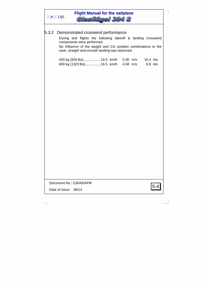
5.3.2 Demonstrated crosswind performance During test flights the following takeoff & landing crosswind components were performed. No influence of the weight and CG position combinations to the save, straight and smooth landing was observed. 420 kg (926 lbs) .................. 19.3 km/h 5.36 m/s 10.4 kts 600 kg (1323 lbs) ................ 16.5 km/h 4.58 m/s 8.9 kts

FFll iigghhtt MMaannuuaall ffoorr tthhee ssaaii llppllaannee
Document No.: G304S/AFM
Date of Issue: 08/14
6-0
H P H Ltd.
SECTION 6
6. Weight and Balance 6.1 Introduction
6.2 Weight and Balance Record and permitted payload-range 6.3 Maximum permitted load of permanent tail water ballast tank 6.4 Maximum permitted load of wing water ballast ta nk 6.5 Maximum permitted load of drainable tail water ballast tank
FFll iigghhtt MMaannuuaall ffoorr tthhee ssaaii llppllaannee
Document No.: G304S/AFM
Date of Issue: 08/14
6-1
H P H Ltd.
6.1 Introduction This Section contains the payload range within the sailplane may be safely operated. Procedures for weighing the sailplane and the calculation method for establishing the permitted payload range and a comprehensive list of all equipment available for this sailplane and the installed equipment during the weighing of the sailplane are contained in the applicable Maintenance Manual, Document Number G304S/MM.
FFll iigghhtt MMaannuuaall ffoorr tthhee ssaaii llppllaannee
Document No.: G304S/AFM
Date of Issue: 08/14
6-2
H P H Ltd.
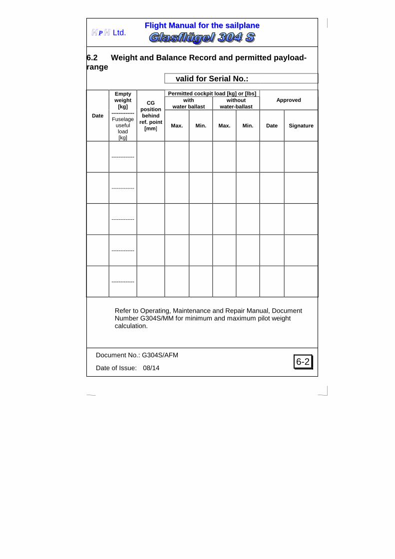
6.2 Weight and Balance Record and permitted payload -range
valid for Serial No.:
Date
Empty weight
[kg] ------------- Fuselage
useful load [kg]
CG position behind
ref. point [mm ]
Permitted cockpit load [kg] or [lbs] Approved with
water ballast without
water-ballast
Max. Min. Max. Min. Date Signature
-------------
-------------
-------------
-------------
-------------
Refer to Operating, Maintenance and Repair Manual, Document Number G304S/MM for minimum and maximum pilot weight calculation.

FFll iigghhtt MMaannuuaall ffoorr tthhee ssaaii llppllaannee
Document No.: G304S/AFM
Date of Issue: 08/14
6-3
H P H Ltd.
6.3 Maximum permitted load of permanent tail water ballast tank
Permanent tail tank CG position 4215 mm aft of ref. point Total tank capacity - standard. / max. 4.0 l / 4.5 l Permanent tail water ballast allows to pilot maintain the flight cg position at optimum range . It could be used either for flights with or without wing water ballast. Adding this ballast limits the minimum pilot’s weight. For filling procedure refer to chapter 4.5.4 Exceeding the maximum permitted useful load of the fuselage stated at table 6.2 must be avoided. Follow the table bellow for setting the maximum permitted load of permanent tail water ballast tank. Minimum pilot seat load
(pilot + parachute) - [kg] Permanent tail water ballast - [l]
Date 0 1 2 3 4 4.5
WARNING
Check permanent water ballast tank load before each flight. Exceeding the maximum permitted load could cause exceeding the aft permitted CG position and affect sailplane controllability and stability.
Example: Weight of pilot and parachute: 75 kg Maximum permanent tail water ballast: 3 l Luggage compartment load: 5 kg Fuselage useful load : 75+3+5=83 kg < 189 kg (see. Tab.6.2)

FFll iigghhtt MMaannuuaall ffoorr tthhee ssaaii llppllaannee
Document No.: G304S/AFM
Date of Issue: 08/14
6-4
H P H Ltd.
6.4 Maximum permitted load of wing water ballast ta nk Max. AUW 600 kg Wing tanks CG position 225 mm aft of ref. point Total tank capacity 194 l For filling procedure refer to chapter 4.5.4. Follow the table bellow for setting the maximum permitted load of wing water ballast tanks.
CAUTION
The luggage compartment may hold a max. load of 10 kg (22 lbs) including all installed equipment, but must be considered when
establishing maximum water ballast.Check if the max. AUW 600 kg will not be exceeded for loading according to the white marked fields.
CAUTION
The outboard wing tanks must be filled in advance. Example: Empty weight: 330 kg Weight of pilot and parachute: 125 kg
Maximum permanent tail water ballast: 4.5 l Luggage compartment load: 10 kg Wing ballast: 134 – 10 = 124kg Max. drainable tail water ballast 6 kg (see ch. 6.5)
AUW: 330+125+4.5+10+124+6=599.5 kg < 600 kg (see ta b. 2.4) Fuselage useful load : 125+4.5+10+6=145.5 kg < 189 kg (see. Tab.6.2)
empty Pilot seat load ( kg ) weight ( pilot + parachute ) (kg) 70 80 90 100 110 120 125 290 194 194 194 194 188 178 174 300 194 194 194 188 178 168 164 310 194 194 188 178 168 158 154 320 194 188 178 168 158 148 144 330 190 178 168 158 148 138 134 340 180 168 158 148 138 128 124
maximum permited wing water balas tank load (l)

FFll iigghhtt MMaannuuaall ffoorr tthhee ssaaii llppllaannee
Document No.: G304S/AFM
Date of Issue: 08/14
6-5
H P H Ltd.
6.5 Maximum permitted load of drainable tail water ballast tank
Drainable tail tank CG position 4215 mm aft of ref. point Total tank capacity 6 l
WARNING
Drainable tail water ballast may be used only for compensating the pitching moment of the wing water ballast load.
For filling procedure refer to chapter 4.5.4. Exceeding the maximum permitted useful load of the fuselage stated at table 6.2 must be avoided. Follow the table bellow for setting the maximum permitted load of drainable tail water ballast tank.
Min
. win
g w
ater
bal
last
load
( l )
194 190 160 130 100 80 60 40 20 0
0 1 2 3 4 5 6
Max. drainable tail waterballast load
( l )
Example: Empty weight: 330 kg Weight of pilot and parachute: 75 kg
Maximum permanent tail water ballast: 3 l Luggage compartment load: 5 kg Wing ballast: 90 l Max. drainable tail water ballast 4 l
AUW: 330+75+3+5+90+4=507 kg < 600 kg (see tab. 2.4) Fuselage useful load : 75+3+5+4=87 kg < 189 kg (see . Tab.6.2)

FFll iigghhtt MMaannuuaall ffoorr tthhee ssaaii llppllaannee
Document No.: G304S/AFM
Date of Issue: 08/14
7-0
H P H Ltd.
SECTION 7
7. GENERAL SAILPLANE AND SYSTEMS DESCRIPTION
7.1 Introduction
7.2 Cockpit controls
7.3 Instrument panel
7.4 Landing gear system
7.5 Seats and safety harness
7.6 Pitot and static system
7.7 Airbrake system
7.8 Baggage compartment
7.9 Water-ballast system

FFll iigghhtt MMaannuuaall ffoorr tthhee ssaaii llppllaannee
Document No.: G304S/AFM
Date of Issue: 08/14
7-1
H P H Ltd.
7.1 Introduction This Section provides description and operation of the sailplane and its systems. Refer to Section 9, Supplements, for details of optional systems and equipment.
7.2 Cockpit controls The below listed controls marked by the appropriate placards (refer to 2.13) are installed in the cockpit. More detailed description of some of the systems may be found below. Control Column Radio button is mounted on the control column: press to transmit. Wheel brake It is controlled by the AIRBRAKE LEVER, at it’s aft position. Tow Release The yellow grip under the Port side of the instrument panel is activating both releases. Air brakes Air brakes are operated by a blue lever located on the port side of the cockpit EXTEND: Unlock (inwards) blue lever on the Port cockpit side and pull towards the rear. RETRACT: Push lever forward and lock. Trim lever is located on the port side of the cockpit. It can be adjusted manually when trim button is unlocked (inwards). Lever forward: nose heavy Lever rearward: tail heavy
FFll iigghhtt MMaannuuaall ffoorr tthhee ssaaii llppllaannee
Document No.: G304S/AFM
Date of Issue: 08/14
7-2
H P H Ltd.
Flaps Unlock (downwards) grey lever on the Port cockpit side, and select flap setting. Flap settings: L: landing position +2: circling in wide thermals +1: circling in narrow thermals and for aero towing 0: best L/D performance (95 – 125 km/h) -1: normal operation speed (110 – 180) -2: normal operation speed (160 – Vne) Keep in mind that the optimum flap setting for given speed is significantly conditioned by current flight weigh. Canopy Lock The white grips on both sides of the cockpit frame serve for the canopy opening-closing. Closing: Handle the canopy frame, pull it downward and push white grips forward until they snap. Opening: Pull both white grips rearward and push canopy frame upward. Cockpit Ventilation Cockpit ventilation is consists of valve at the sailplane nose. It is controlled by the wheel located at the slit opening on the starboard side of the cockpit. Steer the wheel up to open ventilation Steer the wheel down to close ventilation Slit opening closed - air supply to the canopy only Slit opening open - air supply to the pilot as well as to the canopy

FFll iigghhtt MMaannuuaall ffoorr tthhee ssaaii llppllaannee
Document No.: G304S/AFM
Date of Issue: 08/14
7-3
H P H Ltd.
Water ballast Water ballast system is operated with a small lever located on the starboard cockpit side. Lever at rear position: Valves open Lever in forward position: Valves close Backrest adjustment Backrest position may be adjusted with a black "T" lever on the starboard cockpit side under the vent slit opening. Rudder pedal adjustment By pulling the black "T" - grip under the instrument panel, the panel adjustment is unlocked. Forward adjustment: Pull black "T"-grip while pushing pedals forward with heels, release grip and let pedals lock into position. Rear adjustment: Pull pedals back with black grip.
FFll iigghhtt MMaannuuaall ffoorr tthhee ssaaii llppllaannee
Document No.: G304S/AFM
Date of Issue: 08/14
7-4
H P H Ltd.
7.3 Instrument panel
For safety reasons, only a CFRP panel made in accordance to the lay-up plan specified by the manufacturer may be used. Instruments of more than 1 kg (2.2 lbs) need additional support beyond the screws provided. This can be done by means of aluminum straps fixed to the box in front of the instrument panel. Equipment with operating controls must be fitted conveniently within reach, when the pilot is secured in the seat safely. Flight monitoring instruments, like ASI and altimeter, must be mounted within the pilots field of view from which the ASI should be mounted high in the panel in a preferred position.
FFll iigghhtt MMaannuuaall ffoorr tthhee ssaaii llppllaannee
Document No.: G304S/AFM
Date of Issue: 08/14
7-5
H P H Ltd.
7.4 Landing gear system The sailplane is fitted with a damped retractable main wheel and auxiliary tail wheel. The main landing gear is operated with a black lever located on the cockpit starboard side. to retract: Unlock black handle, pull backwards, then lock. to extend: Unlock, push black handle forward and lock. To apply brake on the main wheel, extend the airbrakes fully, the aft travel of the airbrake lever provides the control of the hydraulic wheel brake mechanism. Optional parking brake could be installed.
7.5 Seats and safety harness The sailplane is fitted with an adjustable backrest as well as headrest. The backrest position may be adjusted with a black "T" lever on the starboard cockpit side. To adjust the backrest position release the lever, release weight on the backrest and move your body forward; the backrest moves forward. To adjust the headrest: Lift the locking bar and adjust headrest position. Both backrest and headrest may be adjusted in flight. There are four-point safety harnesses.
7.6 Pitot and static system The static pressure orifices are located on both sides of the fuselage. Total pressure is read in the fin lading edge. Keep the static pressure holes clean, refer to 4.3 Daily inspection .
7.7 Airbrake system The air brakes are controlled with the blue lever located on the port side of the cockpit. To extend the air brakes pull the lever rearward To retract the air brakes push the lever forward

FFll iigghhtt MMaannuuaall ffoorr tthhee ssaaii llppllaannee
Document No.: G304S/AFM
Date of Issue: 08/14
7-6
H P H Ltd.
7.8 Baggage compartment The baggage compartment may carry up to 10 kg (22 lbs) of baggage including all installed equipment.
7.9 Water-ballast system The water-ballast system is operated with a small lever located on the starboard side of the cockpit. open valves – lever in rearward position closed valves – lever in forward position The two replaceable water ballast bags can carry up to 194 liters (aprox. 42 UKgal, 51 USgal).
FFll iigghhtt MMaannuuaall ffoorr tthhee ssaaii llppllaannee
Document No.: G304S/AFM
Date of Issue: 08/14
8-0
H P H Ltd.
SECTION 8
8. Sailplane handling, care and maintenance 8.1 Introduction
8.2 Sailplane inspection periods
8.3 Sailplane alterations or repairs
8.4 Ground handling / road transport
8.5 Cleaning and care

FFll iigghhtt MMaannuuaall ffoorr tthhee ssaaii llppllaannee
Document No.: G304S/AFM
Date of Issue: 08/14
8-1
H P H Ltd.
8.1 Introduction This Section contains manufacturer's recommended procedures for proper ground handling and servicing of the powered sailplane. It also identifies certain inspection and maintenance requirements which must be followed if the sailplane is to retain that new-plane performance and dependability. It is wise to follow a planned schedule of lubrication and preventive maintenance based on climatic and flying conditions encountered.
8.2 Sailplane inspection periods Refer to the Operating, Maintenance and Repair Manual, Document Number G304S/MM for more information on the sailplane periodical inspections.
8.3 Sailplane alterations or repairs It is essential that the responsible airworthiness Authority be contacted prior to any alterations on the sailplane to ensure that the airworthiness of the sailplane is not compromised. Refer to the Operating, Maintenance and Repair Manual, Document Number G304S/MM for more information on the sailplane repairs.

FFll iigghhtt MMaannuuaall ffoorr tthhee ssaaii llppllaannee
Document No.: G304S/AFM
Date of Issue: 08/14
8-2
H P H Ltd.
8.4 Ground handling / road transport The sailplane should only be stored or parked in well ventilated areas. Closed trailers should be equipped with sufficiently large ventilation. Always store with empty water tanks. Take note to store the sailplane without stresses. This is particularly important at higher temperatures. Because of their slim shape, it is particularly important to store the wings correctly. They should be stored with the L.E. pointing downwards and supported under the wing root spar at approx. 2.4 m (7.9 ft) from the wingtip, in a profile true wing sling. Fuselage is correctly stored in a wide fuselage molding in front of the C.G. release, and supported by the tail wheel. The Tailplane is stored in two profile true slings, separated 1.5-2m (5 -6.6 ft.), and with the L.E. pointing downward. Under no circumstances attach the tailplane into the trailer by using the tailplane main attachment fittings. Sailplanes which stay rigged for the whole year or longer periods, should be attended to, so that rigging elements on the fuselage, wing and tailplane do not corrode. Dust covers should be used and are highly recommended. The sailplane should not be parked in the open with the canopy in the open position, as this may act as a concave mirror, and depending on direction of sun-radiation, constitutes a fire hazard. A tail dolly should always be used for ground-handling this sailplane, to prevent unnecessary vibration of the tailplane, and stresses and wear to its attachment fittings. When ground-handling, do not push at wingtips, but rather close to the fuselage.
FFll iigghhtt MMaannuuaall ffoorr tthhee ssaaii llppllaannee
Document No.: G304S/AFM
Date of Issue: 08/14
8-3
H P H Ltd.
8.5 Cleaning and care Wash the surface only with clean water, sponge and chamois. Never use petrol, alcohol or thinners. Soap additives in water should not be used too often. Polish as often as you wish, but take care not to heat up the surface when using a polishing machine, as otherwise the surface quality will suffer. Exposure to moisture should be avoided, as with all other sailplanes. Protect from intensive sun-radiation (heat), and unnecessary permanent load. Please note that the surface of all parts which are exposed to sun-radiation must be colored white. Colors other than white will increase the heat build-up in the GRP, so that insufficient strength will result.
FFll iigghhtt MMaannuuaall ffoorr tthhee ssaaii llppllaannee
Document No.: G304S/AFM
Date of Issue: 08/14
9-0
H P H Ltd.
SECTION 9
9. Supplements 9.1 Introduction
9.2 List of inserted supplements
9.3 Supplements inserted

FFll iigghhtt MMaannuuaall ffoorr tthhee ssaaii llppllaannee
Document No.: G304S/AFM
Date of Issue: 08/14
9-1
H P H Ltd.
9.1 Introduction
9.2 List of inserted supplements
Date of insertion
Doc.No. Title of inserted supplement
08/14 304SFM_Supp_XS 304S Flight Manual Supplement

FFll iigghhtt MMaannuuaall ffoorr tthhee ssaaii llppllaannee
Document No.: 304SFM_Supp_XS
Date of Issue: 08/14
9-0
H P H Ltd.
9.3 Supplements inserted
304SFM_Supp_XS - 304S Flight Manual Supplement
1.1 General
This flight manual supplement covers limitations for sailplanes designated by serial numbers formatted XX-S.
2.1 Introduction
Section 2 includes operating limitations, instrument markings, and basic placards necessary for safe operation of the sailplane, standard systems and standard equipment of gliders designated with plate serial numbers formatted XX-S and equipped with wing s.no. xx-S. The limitations included in Section 2. and in Section 9. have been approved by the EASA.
FFll iigghhtt MMaannuuaall ffoorr tthhee ssaaii llppllaannee
Document No.: 304SFM_Supp_XS
Date of Issue: 08/14
9-1
H P H Ltd.
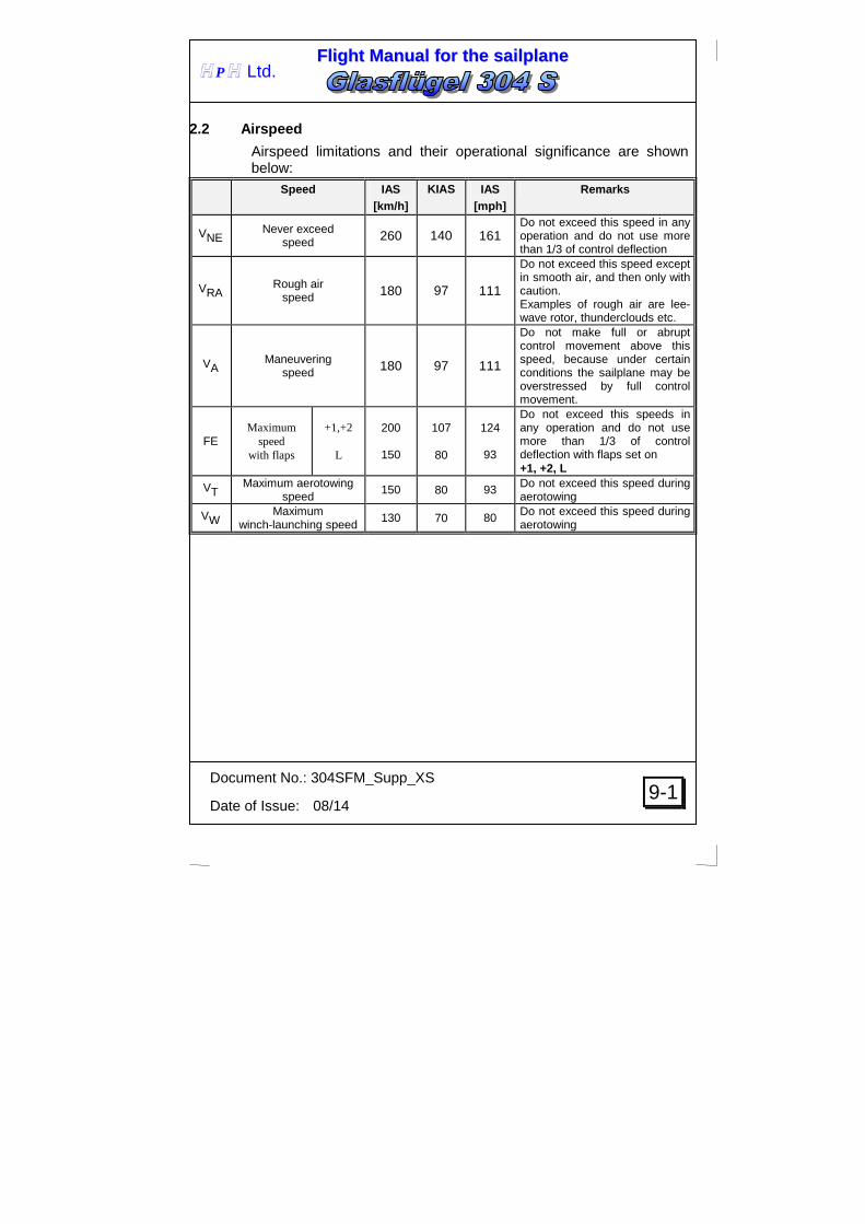
2.2 Airspeed
Airspeed limitations and their operational significance are shown below:
Speed IAS [km/h]
KIAS IAS [mph]
Remarks
VNE Never exceed speed 260 140 161
Do not exceed this speed in any operation and do not use more than 1/3 of control deflection
VRA Rough air speed 180 97 111
Do not exceed this speed except in smooth air, and then only with caution. Examples of rough air are lee-wave rotor, thunderclouds etc.
VA Maneuvering speed 180 97 111
Do not make full or abrupt control movement above this speed, because under certain conditions the sailplane may be overstressed by full control movement.
FE Maximum
speed with flaps
+1,+2
L
200
150
107
80
124
93
Do not exceed this speeds in any operation and do not use more than 1/3 of control deflection with flaps set on +1, +2, L
VT Maximum aerotowing speed
150 80 93 Do not exceed this speed during aerotowing
VW Maximum winch-launching speed
130 70 80 Do not exceed this speed during aerotowing

FFll iigghhtt MMaannuuaall ffoorr tthhee ssaaii llppllaannee
Document No.: 304SFM_Supp_XS
Date of Issue: 08/14
9-2
H P H Ltd.
2.3 Airspeed indicator markings
Marking Value or range IAS Significance [km/h] KIAS [mph]
White Arc
85 - 200 45 - 107 52 - 124
Allowed range for Flaps set to positive position L – white mark and letter at 150 km/h +1, +2 – white mark and letters at 200 km/h
Green arc
94-180 50-97 58-111 Normal operating range
Yellow arc 180-260 97-140 111-161
Maneuvers must be conducted with caution and only in smooth air
Red line
260 140 161
Maximum speed for all operation.
Yellow triangle
94 50 58
Approach speed at maximum weight without water ballast
2.4 Weight
Max. weight of all non-lifting parts 278.5kg 613lbs
2.7 Maneuvering load factors
The following load factors may not be exceeded during maneuvers: n = +5.3 at air speed VA = 180 km/h, 97 KIAS, 111 mph
-2.65 air brakes retracted n = +4.0 at air speed VNE = 260 km/h, 140 KIAS, 161 mph
-1.5 air brakes retracted n = +2 air brakes extended

FFll iigghhtt MMaannuuaall ffoorr tthhee ssaaii llppllaannee
Document No.: 304SFM_Supp_XS
Date of Issue: 08/14
9-3
H P H Ltd.
2.13 Limitation placards
WEIGHT LIMITATION
MAX.TAKEOFF WEIGHT 600 kg 1322 lbs
MAX.WEIGHT OF NON-LIFTING PARTS 278.5 kg 613 lbs
PERMITTED COCKPIT LOAD 70-110 kg 154-242 lbs
FOR COCPIT LOAD LIMITATION REFFER TO ACTUAL WEIGHT AND
BALANCE DATA AT FLIGHT MANUAL SECTION 6
AIRSPEED LIMITATION IAS VA Maneuvering speed 180 km/h 97 KIAS 111 mph
VRA Rough air speed 180 km/h 97 KIAS 111 mph
VT Max. aerotowing speed 150 km/h 80 KIAS 93 mph
VW Max. winchlaunch speed 130 km/h 70 KIAS 80 mph
VLO Max. L/G operating speed 180 km/h 96 KIAS 111 mph
AEROBATIC MANOEUVRES AND INTENTIONAL SPINS ARE PROHIBITED
THE OUTBOARD WING TANKS MUST BE FILLED IN
ADVANCE.