cse 167: introduction to computer graphics lecture #4...
TRANSCRIPT
CSE 167:
Introduction to Computer Graphics
Lecture #4: Vertex Transformation
Jürgen P. Schulze, Ph.D.
University of California, San Diego
Spring Quarter 2016

Announcements
� Project 1 due tomorrow at 2pm
� Grading window is 2-4pm
� Upload source code to TritonEd by 2pm
2
Lecture Overview
� View Volumes
� Vertex Transformation
� Rendering Pipeline
� Culling
3

View Volumes
� View volume = 3D volume seen by camera
World coordinates
Camera coordinates
Perspective view volume
World coordinates
Camera coordinates
Orthographic view volume
4

Projection
matrix
Projection Matrix
Camera coordinates
Canonical view volume
5
Image space
(pixel coordinates)
Viewport
transformation

Orthographic View Volume
� Specified by 6 parameters:
� Right, left, top, bottom, near, far
� Or, if symmetrical:
� Width, height, near, far
6

Orthographic Projection Matrix
Portho(right,left,top,bottom,near, far) =
2
right − left0 0 −
right + left
right − left
02
top − bottom0 −
top + bottom
top − bottom
0 02
far − near
far + near
far − near
0 0 0 1
Portho(width,height,near, far) =
2
width0 0 0
02
height0 0
0 02
far − near
far + near
far − near
0 0 0 1
7
In OpenGL:glOrtho(left, right, bottom, top, near, far)
No equivalent in OpenGL

Perspective View Volume
General view volume
� Defined by 6 parameters, in camera coordinates � Left, right, top, bottom boundaries� Near, far clipping planes
� Clipping planes to avoid numerical problems� Divide by zero� Low precision for distant objects
� Usually symmetric, i.e., left=-right, top=-bottom
Camera
coordinates
8

Perspective View Volume
Symmetrical view volume
� Only 4 parameters
� Vertical field of view (FOV)
� Image aspect ratio (width/height)
� Near, far clipping planes
-z
FOV
y
z=-near
z=-far
y=top
aspect ratio=right − left
top − bottom=
right
top
tan(FOV / 2) =top
near
9
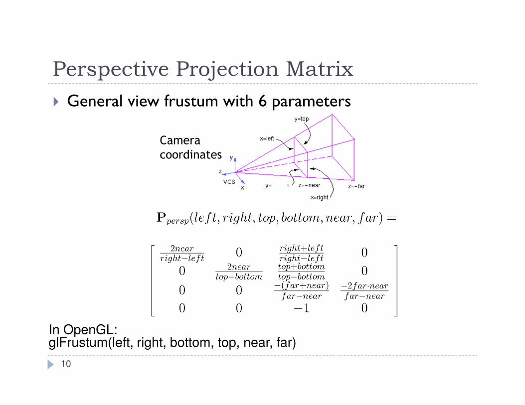
Perspective Projection Matrix
� General view frustum with 6 parameters
Camera
coordinates
10
In OpenGL:glFrustum(left, right, bottom, top, near, far)

Perspective Projection Matrix
� Symmetrical view frustum with field of view, aspect ratio, near and far clip planes
Ppersp (FOV ,aspect,near, far) =
1
aspect ⋅ tan(FOV / 2)0 0 0
01
tan(FOV / 2)0 0
0 0near + far
near − far
2 ⋅ near ⋅ far
near − far
0 0 −1 0
-z
FOV
y
z=-near
z=-far
y=top
Camera
coordinates
11
In OpenGL:
gluPerspective(fov, aspect, near, far)

Canonical View Volume
� Goal: create projection matrix so that
� User defined view volume is transformed into canonical view volume: cube [-1,1]x[-1,1]x[-1,1]
� Multiplying corner vertices of view volume by projection matrix and performing homogeneous divide yields corners of canonical view volume
� Perspective and orthographic projection are treated the same way
� Canonical view volume is last stage in which coordinates are in 3D
� Next step is projection to 2D frame buffer
12

Viewport Transformation
� After applying projection matrix, scene points are in normalized viewing coordinates
� Per definition within range [-1..1] x [-1..1] x [-1..1]
� Next is projection from 3D to 2D (not reversible)
� Normalized viewing coordinates can be mapped to image (=pixel=frame buffer) coordinates
� Range depends on window (view port) size:[x0…x1] x [y0…y1]
� Scale and translation required:
D x0 , x1, y0 , y1( )=
x1 − x0( ) 2 0 0 x0 + x1( ) 2
0 y1 − y0( ) 2 0 y0 + y1( ) 2
0 0 1 2 1 2
0 0 0 1
13
Lecture Overview
� View Volumes
� Vertex Transformation
� Rendering Pipeline
� Culling
14

Complete Vertex Transformation
� Mapping a 3D point in object coordinates to pixel coordinates:
� M: Object-to-world matrix
� C: camera matrix
� P: projection matrix
� D: viewport matrix
Object space
15

Complete Vertex Transformation
� Mapping a 3D point in object coordinates to pixel coordinates:
� M: Object-to-world matrix
� C: camera matrix
� P: projection matrix
� D: viewport matrix
16
Object space
World space

Complete Vertex Transformation
� Mapping a 3D point in object coordinates to pixel coordinates:
� M: Object-to-world matrix
� C: camera matrix
� P: projection matrix
� D: viewport matrix
17
Object space
World space
Camera space

Complete Vertex Transformation
� Mapping a 3D point in object coordinates to pixel coordinates:
� M: Object-to-world matrix
� C: camera matrix
� P: projection matrix
� D: viewport matrix
18
Object space
World space
Camera space
Canonical view volume
Complete Vertex Transformation
� Mapping a 3D point in object coordinates to pixel coordinates:
� M: Object-to-world matrix
� C: camera matrix
� P: projection matrix
� D: viewport matrix
19
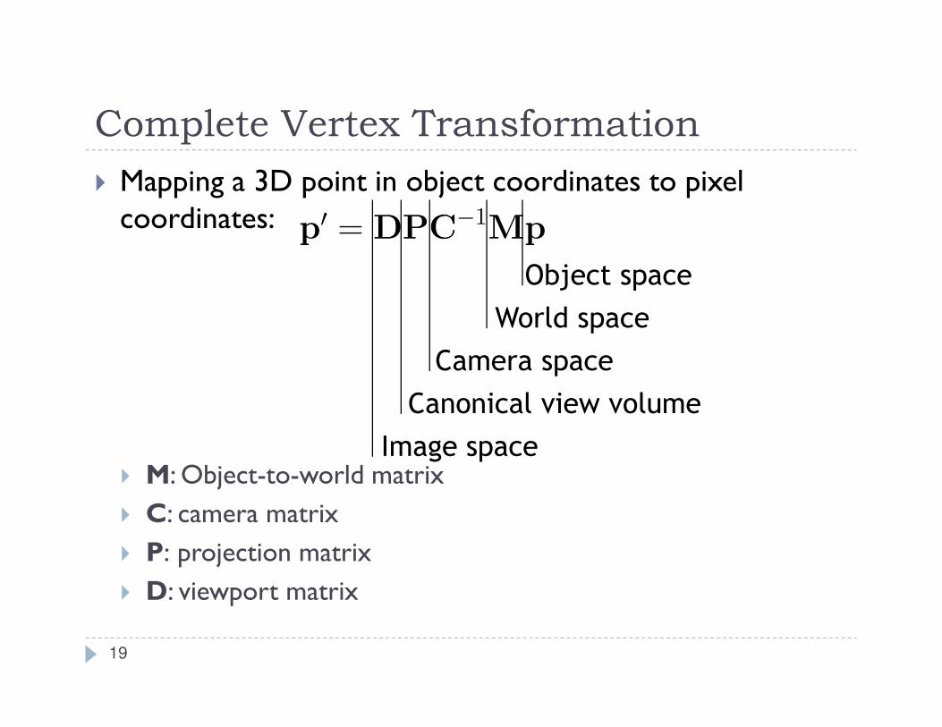
Object space
World space
Camera space
Image space
Canonical view volume

Complete Vertex Transformation
� Mapping a 3D point in object coordinates to pixel coordinates:
� M: Object-to-world matrix
� C: camera matrix
� P: projection matrix
� D: viewport matrix
20
Pixel coordinates:

The Complete Vertex Transformation
21
Model Matrix
Camera Matrix
Projection Matrix
Viewport Matrix
Object Coordinates
World Coordinates
Camera Coordinates
Canonical View Volume Coordinates
Window Coordinates

Complete Vertex Transformation in OpenGL
� Mapping a 3D point in object coordinates to pixel coordinates:
� M: Object-to-world matrix
� C: camera matrix
� P: projection matrix
� D: viewport matrix
22
OpenGL GL_MODELVIEW matrix
OpenGL GL_PROJECTION matrix

Complete Vertex Transformation in OpenGL
� GL_MODELVIEW, C-1M� Defined by the programmer.
� Think of the ModelView matrix as where you stand with the camera and the direction you point it.
� GL_PROJECTION, P� Utility routines to set it by specifying view volume:
glFrustum(), gluPerspective(), glOrtho()
� Think of the projection matrix as describing the attributes of your camera, such as field of view, focal length, etc.
� Viewport, D
� Specify implicitly via glViewport()
� No direct access with equivalent to GL_MODELVIEW or GL_PROJECTION
23

Introduction to OpenGL
� Using slides from SIGGRAPH course:
24

25
OpenGL and GLFW Overview
� What is OpenGL & what can it do for me?
� OpenGL in windowing systems
� Why GLFW
� A GLFW program template

26
What Is OpenGL?
� Graphics rendering API
� high-quality color images composed of geometric and image primitives
� window system independent
� operating system independent

27
OpenGL as a Renderer
� Geometric primitives
� points, lines and polygons
� Image Primitives
� images and bitmaps
� separate pipeline for images and geometry
� linked through texture mapping
� Rendering depends on state
� colors, materials, light sources, etc.

28
Related APIs
� GLU (OpenGL Utility Library)
� part of OpenGL
� NURBS, tessellators, quadric shapes, etc.
� GLFW (OpenGL Utility Toolkit)
� portable windowing API
� not officially part of OpenGL

29
Preliminaries
� Headers Files� #include <GL/gl.h>
� #include <GL/glu.h>
� #include <GLFW/glfw3.h>
� Libraries
� Enumerated Types
� OpenGL defines numerous types for compatibility� GLfloat, GLint, GLenum, etc.

30
GLFW Basics
� Application Structure
� Configure and open window
� Initialize OpenGL state
� Enter event processing loop

31
Sample Program#include <GLFW/glfw3.h>
int main(void)
{
GLFWwindow* window;
/* Initialize the library */
if (!glfwInit()) return -1;
/* Create a windowed mode window and its OpenGL context */
window = glfwCreateWindow(640, 480, "Hello CSE 167", NULL, NULL);
if (!window)
{
glfwTerminate();
return -1;
}
/* Make the window's context current */
glfwMakeContextCurrent(window);
/* Initialize OpenGL here */
/* Loop until the user closes the window */
while (!glfwWindowShouldClose(window))
{
/* Render here with OpenGL */
/* Swap front and back buffers */
glfwSwapBuffers(window);
/* Poll for and process events */
glfwPollEvents();
}
glfwTerminate();
return 0;
}
32
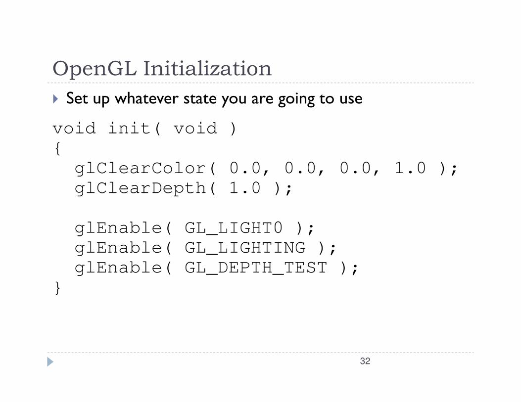
OpenGL Initialization
� Set up whatever state you are going to use
void init( void )
{
glClearColor( 0.0, 0.0, 0.0, 1.0 );
glClearDepth( 1.0 );
glEnable( GL_LIGHT0 );
glEnable( GL_LIGHTING );
glEnable( GL_DEPTH_TEST );
}

Elementary Rendering
� Geometric Primitives
� Managing OpenGL State
� OpenGL Buffers
33

OpenGL Geometric Primitives
� All geometric primitives are specified by vertices
34
GL_QUAD_STRIP
GL_POLYGON
GL_TRIANGLE_STRIP GL_TRIANGLE_FAN
GL_POINTS
GL_LINES
GL_LINE_LOOPGL_LINE_STRIP
GL_TRIANGLES
GL_QUADS

Simple Examplevoid drawRhombus( GLfloat color[] )
{glBegin( GL_QUADS );glColor3fv( color );glVertex2f( 0.0, 0.0 );glVertex2f( 1.0, 0.0 );glVertex2f( 1.5, 1.118 );glVertex2f( 0.5, 1.118 );glEnd();
}
35

36
OpenGL Command Formats
glVertex3fv( v )
Number of
components
2 - (x,y)
3 - (x,y,z)
4 - (x,y,z,w)
Data Type
b - byte
ub - unsigned byte
s - short
us - unsigned short
i - int
ui - unsigned int
f - float
d - double
Vector
omit “v” for
scalar form
glVertex2f( x, y )

37
Specifying Geometric Primitives
� Primitives are specified usingglBegin( primType );
glEnd();
� primType determines how vertices are combined
GLfloat red, greed, blue;Glfloat coords[3];
glBegin( primType );for ( i = 0; i < nVerts; ++i ) {
glColor3f( red, green, blue );glVertex3fv( coords );
}glEnd();

38
Shapes Tutorial

OpenGL’s State Machine
� All rendering attributes are encapsulated in the OpenGL State
� rendering styles
� shading
� lighting
� texture mapping
39

Manipulating OpenGL State
� Appearance is controlled by current statefor each ( primitive to render ) {
update OpenGL staterender primitive
}
� Manipulating vertex attributes is mostcommon way to manipulate stateglColor*() / glIndex*()
glNormal*()
glTexCoord*()
40

Controlling current state
� Setting StateglPointSize( size );
glLineStipple( repeat, pattern );
glShadeModel( GL_SMOOTH );
� Enabling FeaturesglEnable( GL_LIGHTING );
glDisable( GL_TEXTURE_2D );
41