cse 167: introduction to computer graphics lecture #12: glsl
TRANSCRIPT

CSE 167:
Introduction to Computer Graphics
Lecture #12: GLSL
Jürgen P. Schulze, Ph.D.
University of California, San Diego
Fall Quarter 2014

Announcements
� Project 5 due Friday at 3:30pm
� 2 REU positions for high speed networking
� Under Dr. Thomas DeFanti
2

Overview
� Bi-linear patch
� Bi-cubic Bézier patch
� Advanced parametric surfaces
3

Bilinear Patch
� Visualization
4
Bilinear Patches
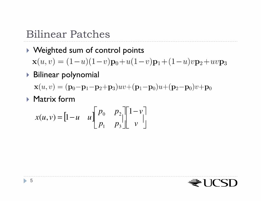
� Weighted sum of control points
� Bilinear polynomial
� Matrix form
5
[ ]
−
−=
v
v
pp
ppuuvux
11),(
31
20
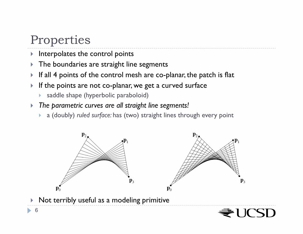
Properties� Interpolates the control points
� The boundaries are straight line segments
� If all 4 points of the control mesh are co-planar, the patch is flat
� If the points are not co-planar, we get a curved surface
� saddle shape (hyperbolic paraboloid)
� The parametric curves are all straight line segments!
� a (doubly) ruled surface: has (two) straight lines through every point
� Not terribly useful as a modeling primitive
6

Overview
� Bi-linear patch
� Bi-cubic Bézier patch
� Advanced parametric surfaces
7

Bicubic Bézier patch
� Grid of 4x4 control points, p0 through p15� Four rows of control points define Bézier curves along u
p0,p1,p2,p3; p4,p5,p6,p7; p8,p9,p10,p11; p12,p13,p14,p15
� Four columns define Bézier curves along vp0,p4,p8,p12; p1,p6,p9,p13; p2,p6,p10,p14; p3,p7,p11,p15
p0p1
p2
p3
p4 p5
p6
p7
p8p9
p10
p11
p12 p13
p14 p15
u
v
8

Bézier Patch (Step 1)
� Evaluate four u-direction Bézier curves at scalar value u [0..1]
� Get points q0 … q3
p0p1
p2
p3
p4 p5
p6
p7
p8p9
p10
p11
p12 p13
p14 p15
u
v
q0
q1
q2
q3
q0 = Bez(u,p0,p
1,p
2,p
3)
q1 = Bez(u,p4 ,p5 ,p6 ,p7 )
q2 = Bez(u,p8 ,p9 ,p10 ,p11)
q3 = Bez(u,p12 ,p13,p14 ,p15 )
9

Bézier Patch (Step 2)
� Points q0 … q3 define a Bézier curve
� Evaluate it at v [0..1]
p0p1
p2
p3
p4 p5
p6
p7
p8p9
p10
p11
p12 p13
p14 p15
u
v
q0
q1
q2
q3
x
x(u,v) = Bez(v,q0,q
1,q
2,q
3)
10
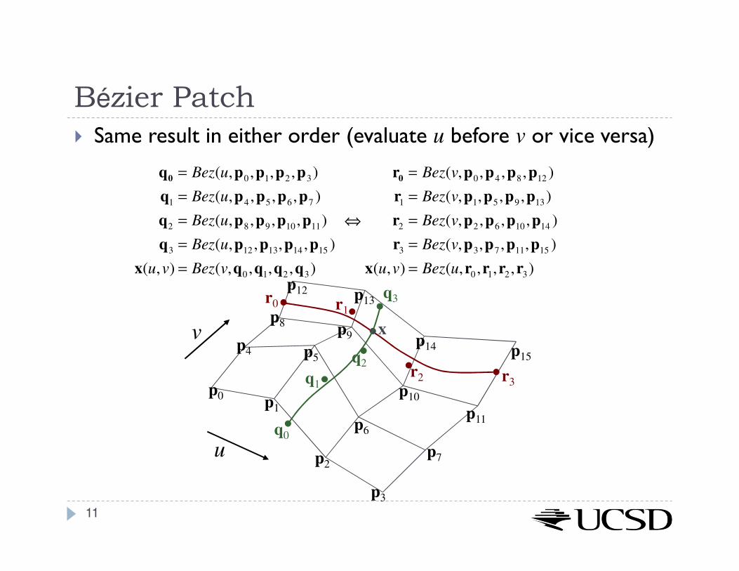
Bézier Patch
� Same result in either order (evaluate u before v or vice versa)
q0 = Bez(u,p0,p
1,p
2,p
3)
q1
= Bez(u,p4,p
5,p
6,p
7)
q2
= Bez(u,p8,p
9,p
10,p
11)
q3
= Bez(u,p12
,p13
,p14
,p15
)
x(u,v) = Bez(v,q0 ,q1,q2 ,q3)
⇔
r0 = Bez(v,p0,p
4,p
8,p
12)
r1
= Bez(v,p1,p
5,p
9,p
13)
r2
= Bez(v,p2,p
6,p
10,p
14)
r3
= Bez(v,p3,p
7,p
11,p
15)
x(u,v) = Bez(u,r0 ,r1,r2 ,r3)
p0p1
p2
p3
p4 p5
p6
p7
p8p9
p10
p11
p12 p13
p14 p15
u
v
r0 r1
r2 r3
x
q0
q1
q2
q3
11

12
U =
u3
u2
u
1
V =
v3
v2
v
1
BBez =
−1 3 −3 1
3 −6 3 0
−3 3 0 0
1 0 0 0
= BBez
T
Cx = BBez
TGxBBez
Cy = BBez
T GyBBez
Cz = BBez
T GzBBez
Gx =
p0 x p
1x p2 x p
3x
p4 x p
5 x p6 x p
7 x
p8 x p
9 x p10 x p
11x
p12 x p
13x p14 x p
15 x
, Gy = L, Gz = L
x u,v( )=
VTCxU
VT CyU
VT CzU
Bézier Patch: Matrix Form

13
Bézier Patch: Matrix Form
� Cx stores the coefficients of the bicubic equation for x
� Cy stores the coefficients of the bicubic equation for y
� Cz stores the coefficients of the bicubic equation for z
� Gx stores the geometry (x components of the control points)
� Gy stores the geometry (y components of the control points)
� Gz stores the geometry (z components of the control points)
� BBez is the basis matrix (Bézier basis)
� U and V are the vectors formed from the powers of u and v
� Compact notation
� Leads to efficient method of computation
� Can take advantage of hardware support for 4x4 matrix arithmetic

Properties
� Convex hull: any point on the surface will fall within the convex hull of the control points
� Interpolates 4 corner points
� Approximates other 12 points, which act as “handles”
� The boundaries of the patch are the Bézier curves defined by the points on the mesh edges
� The parametric curves are all Bézier curves
14
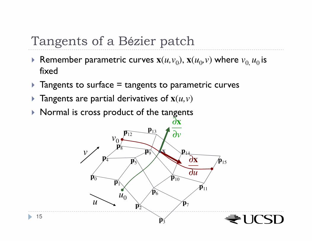
Tangents of a Bézier patch
� Remember parametric curves x(u,v0), x(u0,v) where v0, u0 is fixed
� Tangents to surface = tangents to parametric curves
� Tangents are partial derivatives of x(u,v)
� Normal is cross product of the tangents
p0p1
p2
p3
p4 p5
p6
p7
p8p9
p10
p11
p12p13
p14
p15
u
v
u0
x
∂x
∂u
∂x
∂vv0
15
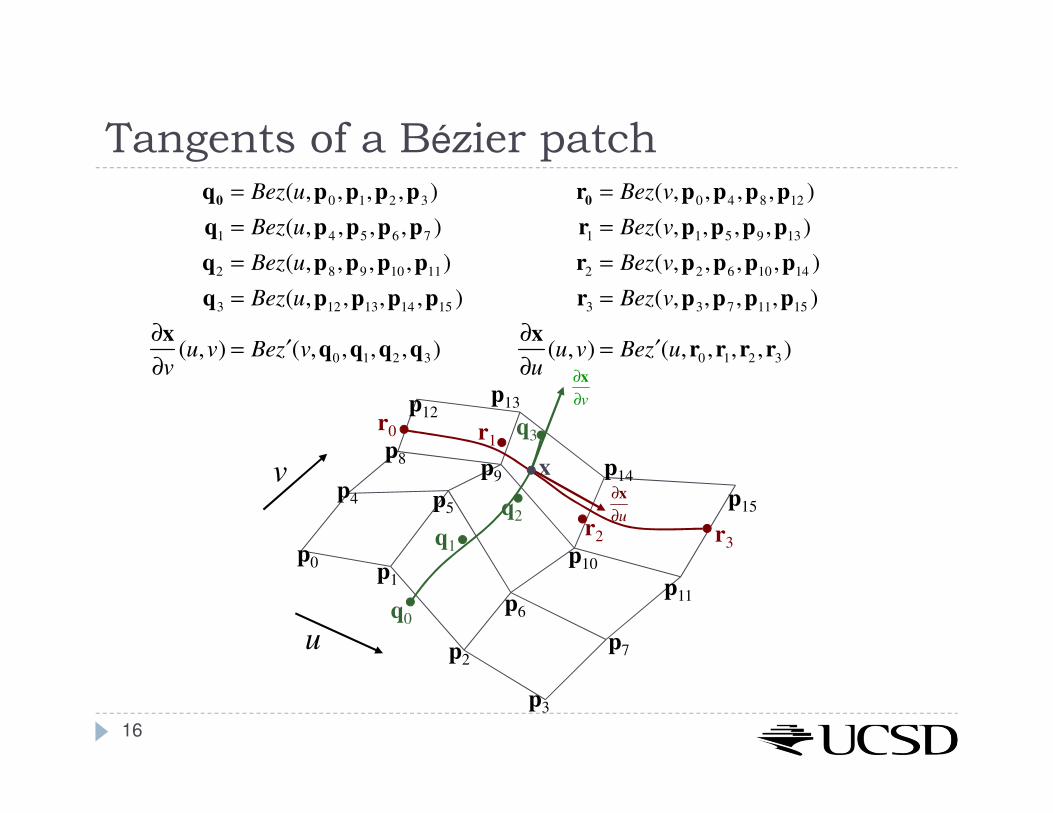
Tangents of a Bézier patchq0 = Bez(u,p0 ,p1,p2 ,p3)
q1 = Bez(u,p4 ,p5 ,p6 ,p7 )
q2 = Bez(u,p8 ,p9 ,p10 ,p11)
q3 = Bez(u,p12 ,p13,p14 ,p15 )
∂x
∂v(u,v) = Be ′z (v,q0 ,q1,q2 ,q3)
r0 = Bez(v,p0 ,p4 ,p8 ,p12 )
r1 = Bez(v,p1,p5 ,p9 ,p13)
r2 = Bez(v,p2 ,p6 ,p10 ,p14 )
r3 = Bez(v,p3,p7 ,p11,p15 )
∂x
∂u(u,v) = Be ′z (u,r0 ,r1,r2 ,r3)
p0p1
p2
p3
p4 p5
p6
p7
p8p9
p10
p11
p12p13
p14
p15
u
v
r0 r1
r2 r3
x
q0
q1
q2
q3
∂x
∂u
∂x
∂v
16
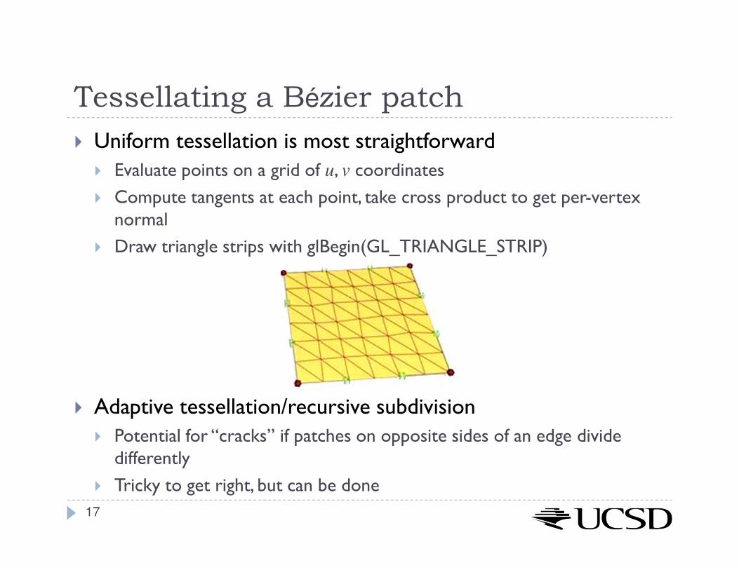
Tessellating a Bézier patch
� Uniform tessellation is most straightforward
� Evaluate points on a grid of u, v coordinates
� Compute tangents at each point, take cross product to get per-vertex normal
� Draw triangle strips with glBegin(GL_TRIANGLE_STRIP)
� Adaptive tessellation/recursive subdivision
� Potential for “cracks” if patches on opposite sides of an edge divide differently
� Tricky to get right, but can be done
17
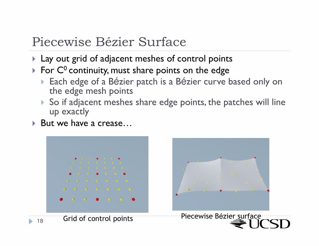
Piecewise Bézier Surface
� Lay out grid of adjacent meshes of control points� For C0 continuity, must share points on the edge
� Each edge of a Bézier patch is a Bézier curve based only on the edge mesh points
� So if adjacent meshes share edge points, the patches will line up exactly
� But we have a crease…
Grid of control points Piecewise Bézier surface18
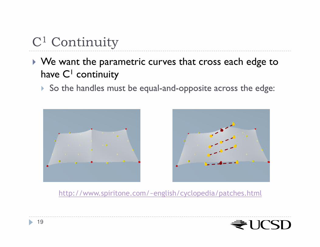
C1 Continuity
� We want the parametric curves that cross each edge to have C1 continuity
� So the handles must be equal-and-opposite across the edge:
http://www.spiritone.com/~english/cyclopedia/patches.html
19

Modeling With Bézier Patches� Original Utah teapot, from Martin Newell's PhD thesis, consisted of 28 Bézier patches.
� The original had no rim for the lid and no bottom
� Later, four more patches were added to create a bottom, bringing the total to 32
� The data set was used by a number of people, including graphics guru Jim Blinn. In a demonstration of a system of his he scaled the teapot by .75, creating a stubbier teapot. He found it more pleasing to the eye, and it was this scaled version that became the highly popular dataset used today.
20 Source: http://www.holmes3d.net/graphics/teapot/

Overview
� Bi-linear patch
� Bi-cubic Bézier patch
� Advanced parametric surfaces
21
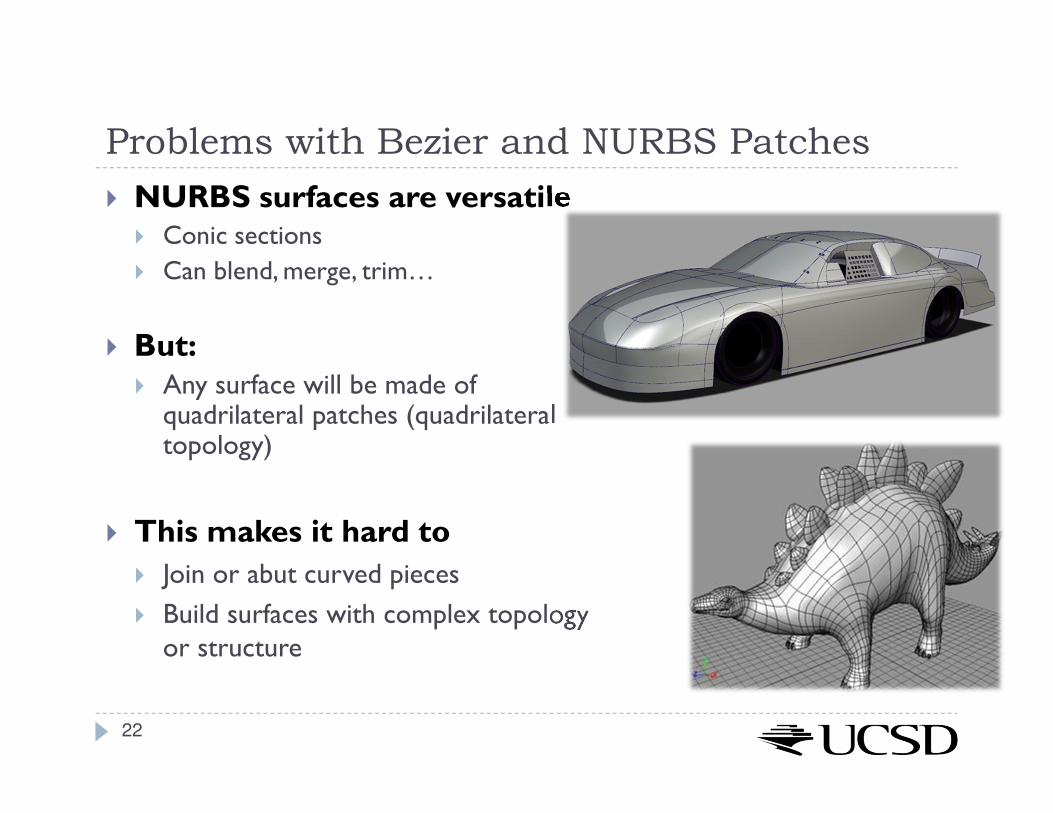
Problems with Bezier and NURBS Patches
� NURBS surfaces are versatile� Conic sections
� Can blend, merge, trim…
� But:� Any surface will be made of quadrilateral patches (quadrilateral topology)
� This makes it hard to
� Join or abut curved pieces
� Build surfaces with complex topology or structure
22
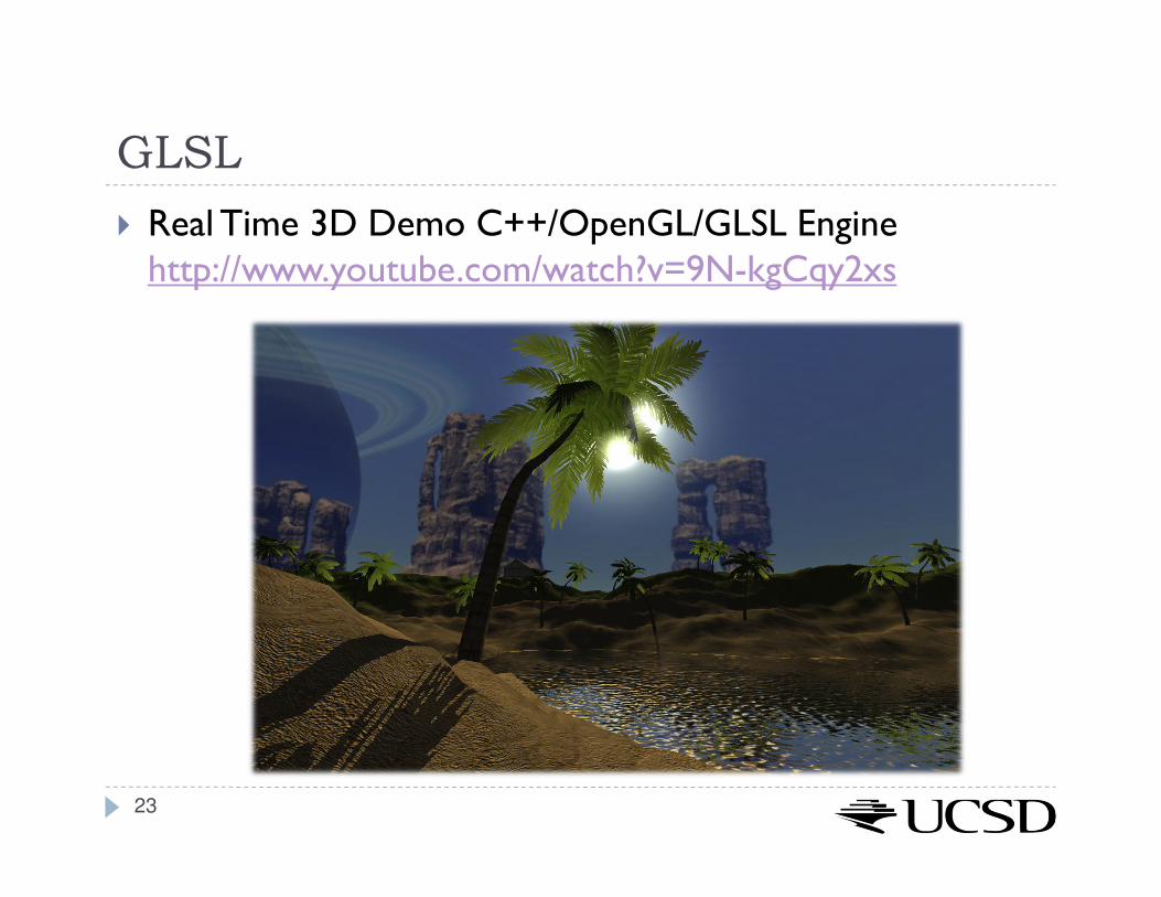
GLSL
� Real Time 3D Demo C++/OpenGL/GLSL Engine http://www.youtube.com/watch?v=9N-kgCqy2xs
23

Lecture Overview
� Programmable Shaders
� Vertex Programs
� Fragment Programs
� GLSL
24

Shader Programs
� Programmable shaders consist of shader programs
� Written in a shading language
� Syntax similar to C language
� Each shader is a separate piece of code in a separate ASCII text file
� Shader types:
� Vertex shader
� Tessellation shader
� Geometry shader
� Fragment shader (a.k.a. pixel shader)
� The programmer can provide any number of shader types to work together to achieve a certain effect
� If a shader type is not provided, OpenGL’s fixed-function pipeline is used
25

Frame-buffer access
(z-buffering)
Programmable Pipeline
� Executed once per vertex:
� Vertex Shader
� Tessellation Shader
� Geometry Shader
� Executed once per fragment:
� Fragment Shader
26
Modeling and viewing
transformation
Shading
Projection
Rasterization
Scene
Image
Fragment processing

Vertex Shader
� Executed once per vertex
� Cannot create or remove vertices
� Does not know the primitive it belongs to
� Replaces functionality for
� Model-view, projection transformation
� Per-vertex shading
� If you use a vertex program, you need to implement behavior for the above functionality in the program!
� Typically used for:
� Character animation
� Particle systems
27

Tessellation Shader
� Executed once per primitive
� Generates new primitives by subdividing each line, triangle or quad primitive
� Typically used for:
� Adapting visual quality to the required level of detail
� For instance, for automatic tessellation of Bezier curves and surfaces
� Geometry compression: 3D models stored at coarser level of resolution, expanded at runtime
� Allows detailed displacement maps for less detailed geometry
28

Geometry Shader
� Executed once per primitive (triangle, quad, etc.)
� Can create new graphics primitives from output of tessellation shader (e.g., points, lines, triangles)
� Or can remove the primitive
� Typically used for:
� Per-face normal computation
� Easy wireframe rendering
� Point sprite generation
� Shadow volume extrusion
� Single pass rendering to a cube map
� Automatic mesh complexity modification (depending on resolution requirements)
29

Fragment Shader
� A.k.a. Pixel Shader
� Executed once per fragment
� Cannot access other pixels or vertices
� Makes execution highly parallelizable
� Computes color, opacity, z-value, texture coordinates
� Typically used for:
� Per-pixel shading (e.g., Phong shading)
� Advanced texturing
� Bump mapping
� Shadows30

Lecture Overview
� Programmable Shaders
� Vertex Programs
� Fragment Programs
� GLSL
31
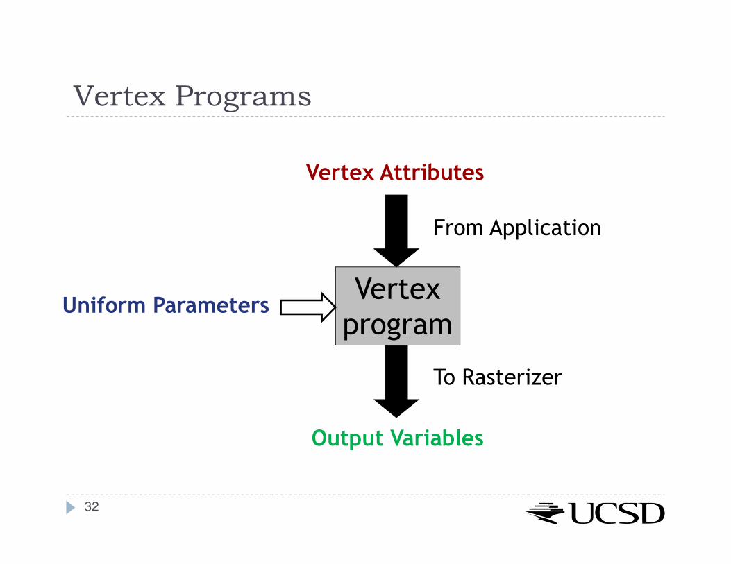
Vertex Programs
Vertex
program
Vertex Attributes
From Application
To Rasterizer
Output Variables
Uniform Parameters
32

Vertex Attributes
� Declared using the attribute storage classifier
� Different for each execution of the vertex program
� Can be modified by the vertex program
� Two types:
� Pre-defined OpenGL attributes. Examples:attribute vec4 gl_Vertex;
attribute vec3 gl_Normal;
attribute vec4 gl_Color;
� User-defined attributes. Example:attribute float myAttrib;
33
Uniform Parameters
� Declared by uniform storage classifier
� Normally the same for all vertices
� Read-only
� Two types:
� Pre-defined OpenGL state variables
� User-defined parameters
34

Uniform Parameters: Pre-Defined
� Provide access to the OpenGL state
� Examples for pre-defined variables:uniform mat4 gl_ModelViewMatrix;
uniform mat4 gl_ModelViewProjectionMatrix;
uniform mat4 gl_ProjectionMatrix;
uniform gl_LightSourceParameters
gl_LightSource[gl_MaxLights];
35

Uniform Parameters: User-Defined
� Parameters that are set by the application
� Should not be changed frequently
� Especially not on a per-vertex basis!
� To access, use glGetUniformLocation, glUniform*
in application
� Example:
� In shader declareuniform float a;
� Set value of a in application:GLuint p;
int i = glGetUniformLocation(p,”a”);
glUniform1f(i, 1.0f);
36
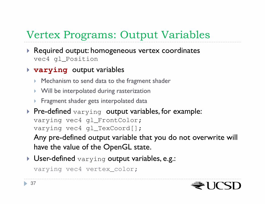
Vertex Programs: Output Variables
� Required output: homogeneous vertex coordinatesvec4 gl_Position
� varying output variables
� Mechanism to send data to the fragment shader
� Will be interpolated during rasterization
� Fragment shader gets interpolated data
� Pre-defined varying output variables, for example:varying vec4 gl_FrontColor;
varying vec4 gl_TexCoord[];
Any pre-defined output variable that you do not overwrite will have the value of the OpenGL state.
� User-defined varying output variables, e.g.:
varying vec4 vertex_color;
37

Lecture Overview
� Programmable Shaders
� Vertex Programs
� Fragment Programs
� GLSL
38

Fragment Programs
Fragment
program
Fragment Data
From Rasterizer
To Frame Buffer
Output Variables
Uniform Parameters
39

Fragment Data
� Changes for each execution of the fragment program
� Fragment data includes:
� Interpolated standard OpenGL variables for fragment shader, as generated by vertex shader, for example:varying vec4 gl_Color;
varying vec4 gl_TexCoord[];
� Interpolated varying variables from vertex shader
� Allows data to be passed from vertex to fragment shader
40
Uniform Parameters
� Same as in vertex programs
41

Output Variables
� Pre-defined output variables:� gl_FragColor
� gl_FragDepth
� OpenGL writes these to the frame buffer
� Result is undefined if you do not set these variables!
42

Creating Shaders in OpenGL
Source: Gabriel Zachmann, Clausthal University
43
Tutorials and Documentation
� OpenGL and GLSL Specifications
� https://www.opengl.org/registry/
� GLSL Tutorials
� http://www.lighthouse3d.com/opengl/glsl/
� http://www.clockworkcoders.com/oglsl/tutorials.html
� OpenGL Programming Guide (Red Book)
� http://www.glprogramming.com/red/
� OpenGL Shading Language (Orange Book)
� http://wiki.labomedia.org/images/1/10/Orange_Book_-_OpenGL_Shading_Language_2nd_Edition.pdf
� OpenGL 4.5 API Reference Card
� https://www.opengl.org/sdk/docs/reference_card/opengl45-reference-card.pdf
44