cs228 skiddingresistance...designmanualforroadsandbridges pavement inspection&assessment cs228...
TRANSCRIPT

Design Manual for Roads and Bridges
PavementInspection & Assessment
CS 228Skidding resistance(formerly HD 28/15)
Revision 0
SummaryThis document describes the requirements for the provision and management of appropriatelevels of skid resistance on UK motorway and all-purpose trunk roads. It describes therequirements for making and interpreting measurements of skid resistance. It also provides amethod to identify locations for treatment to improve skid resistance where that treatment is likelyto reduce the risk of skidding related incidents in wet conditions. This document is complementedby DMRB document HD 36/15, which sets out the requirements and associated advice onsurfacing material characteristics necessary to deliver the required skid resistance properties.
Application by Overseeing OrganisationsAny specific requirements for Overseeing Organisations alternative or supplementary to those given in this documentare given in National Application Annexes to this document.
Feedback and EnquiriesUsers of this document are encouraged to raise any enquiries and/or provide feedback on the content and usageof this document to the dedicated Highways England team. The email address for all enquiries and feedback is:[email protected]
This is a controlled document.

CS 228 Revision 0 Contents
Contents
Release notes 3
Foreword 4Publishing information . . . . . . . . . . . . . . . . . . . . . . . . . . . . . . . . . . . . . . . . . . . . . . . . 4Contractual and legal considerations . . . . . . . . . . . . . . . . . . . . . . . . . . . . . . . . . . . . . . . . 4
Introduction 5Background . . . . . . . . . . . . . . . . . . . . . . . . . . . . . . . . . . . . . . . . . . . . . . . . . . . . . . 5Assumptions made in the preparation of this document . . . . . . . . . . . . . . . . . . . . . . . . . . . . . 5Mutual Recognition . . . . . . . . . . . . . . . . . . . . . . . . . . . . . . . . . . . . . . . . . . . . . . . . . 5
Abbreviations 6
Terms and definitions 7
1. Scope 8Aspects covered . . . . . . . . . . . . . . . . . . . . . . . . . . . . . . . . . . . . . . . . . . . . . . . . . . . 8Implementation . . . . . . . . . . . . . . . . . . . . . . . . . . . . . . . . . . . . . . . . . . . . . . . . . . . 8Use of GG 101 . . . . . . . . . . . . . . . . . . . . . . . . . . . . . . . . . . . . . . . . . . . . . . . . . . . . 8
2. Operation 9
3. Measurement of skid resistance 12Overview . . . . . . . . . . . . . . . . . . . . . . . . . . . . . . . . . . . . . . . . . . . . . . . . . . . . . . . 12Determine the survey procedure . . . . . . . . . . . . . . . . . . . . . . . . . . . . . . . . . . . . . . . . . . 14Plan surveys . . . . . . . . . . . . . . . . . . . . . . . . . . . . . . . . . . . . . . . . . . . . . . . . . . . . . 14Conduct surveys . . . . . . . . . . . . . . . . . . . . . . . . . . . . . . . . . . . . . . . . . . . . . . . . . . . 15Process survey data . . . . . . . . . . . . . . . . . . . . . . . . . . . . . . . . . . . . . . . . . . . . . . . . . 15Check survey coverage . . . . . . . . . . . . . . . . . . . . . . . . . . . . . . . . . . . . . . . . . . . . . . . 16Apply seasonal correction . . . . . . . . . . . . . . . . . . . . . . . . . . . . . . . . . . . . . . . . . . . . . . 16
4. Setting the investigatory level 17Overview . . . . . . . . . . . . . . . . . . . . . . . . . . . . . . . . . . . . . . . . . . . . . . . . . . . . . . . 17Allocate site category and investigatory level . . . . . . . . . . . . . . . . . . . . . . . . . . . . . . . . . . . 18Identify sections for review . . . . . . . . . . . . . . . . . . . . . . . . . . . . . . . . . . . . . . . . . . . . . 19Record updated ILs and review date . . . . . . . . . . . . . . . . . . . . . . . . . . . . . . . . . . . . . . . . 19
5. Initial investigation 20Overview . . . . . . . . . . . . . . . . . . . . . . . . . . . . . . . . . . . . . . . . . . . . . . . . . . . . . . . 20Identify sites at or below the IL . . . . . . . . . . . . . . . . . . . . . . . . . . . . . . . . . . . . . . . . . . . 21Identify other sites requiring investigation . . . . . . . . . . . . . . . . . . . . . . . . . . . . . . . . . . . . . 21Data validation . . . . . . . . . . . . . . . . . . . . . . . . . . . . . . . . . . . . . . . . . . . . . . . . . . . . 21Identify sites for detailed investigation . . . . . . . . . . . . . . . . . . . . . . . . . . . . . . . . . . . . . . . 21
6. Detailed site investigation and prioritisation 23Collate data . . . . . . . . . . . . . . . . . . . . . . . . . . . . . . . . . . . . . . . . . . . . . . . . . . . . . . 25Plan investigations . . . . . . . . . . . . . . . . . . . . . . . . . . . . . . . . . . . . . . . . . . . . . . . . . . 25Carry out site investigations . . . . . . . . . . . . . . . . . . . . . . . . . . . . . . . . . . . . . . . . . . . . . 26Maintenance prioritisation and programming . . . . . . . . . . . . . . . . . . . . . . . . . . . . . . . . . . . 27
7. Use of slippery road warning signs 28Overview . . . . . . . . . . . . . . . . . . . . . . . . . . . . . . . . . . . . . . . . . . . . . . . . . . . . . . . 28Determine locations requiring warning signs . . . . . . . . . . . . . . . . . . . . . . . . . . . . . . . . . . . . 30Review locations of existing signs . . . . . . . . . . . . . . . . . . . . . . . . . . . . . . . . . . . . . . . . . 30Install / remove signs as necessary . . . . . . . . . . . . . . . . . . . . . . . . . . . . . . . . . . . . . . . . . 30
8. Normative references 31
1

CS 228 Revision 0 Contents
9. Informative references 32
Appendix A. Application of site categories and Investigatory Levels 33A1 Overview . . . . . . . . . . . . . . . . . . . . . . . . . . . . . . . . . . . . . . . . . . . . . . . . . . . . . 33A2 Category A: Motorway . . . . . . . . . . . . . . . . . . . . . . . . . . . . . . . . . . . . . . . . . . . . . . 33A3 Category B: Non-event carriageway with one-way traffic . . . . . . . . . . . . . . . . . . . . . . . . . . . 33A4 Category C: Non-event carriageway with two-way traffic . . . . . . . . . . . . . . . . . . . . . . . . . . . 34A5 Category Q: Approaches to and across minor and major junctions, approaches to roundabouts and traffic
signals . . . . . . . . . . . . . . . . . . . . . . . . . . . . . . . . . . . . . . . . . . . . . . . . . . . . . . 34A5.1 Approaches to junctions: . . . . . . . . . . . . . . . . . . . . . . . . . . . . . . . . . . . . . . . . . 34A5.2 Approaches to roundabouts and traffic signals: . . . . . . . . . . . . . . . . . . . . . . . . . . . . 35
A6 Category K: Approaches to pedestrian crossings and other high risk situations . . . . . . . . . . . . . . 35A7 Category R: Roundabout . . . . . . . . . . . . . . . . . . . . . . . . . . . . . . . . . . . . . . . . . . . . 36A8 Category G1: Gradient 5-10% longer than 50m . . . . . . . . . . . . . . . . . . . . . . . . . . . . . . . . 36A9 Category G2: Gradient >10% longer than 50m . . . . . . . . . . . . . . . . . . . . . . . . . . . . . . . . 36A10 Category S1/S2: Bend radius < 500m . . . . . . . . . . . . . . . . . . . . . . . . . . . . . . . . . . . . 37A11 Examples . . . . . . . . . . . . . . . . . . . . . . . . . . . . . . . . . . . . . . . . . . . . . . . . . . . . 37
A11.1 Example: Motorway grade separated junction . . . . . . . . . . . . . . . . . . . . . . . . . . . . 37A11.2 Example: T-junction on a single carriageway . . . . . . . . . . . . . . . . . . . . . . . . . . . . . 38A11.3 Example: Priority junction . . . . . . . . . . . . . . . . . . . . . . . . . . . . . . . . . . . . . . . 39A11.4 Example: Roundabout with a pedestrian crossing . . . . . . . . . . . . . . . . . . . . . . . . . . 40A11.5 Example: Signal controlled crossroads involving a dual carriageway road and a single carriage-
way road . . . . . . . . . . . . . . . . . . . . . . . . . . . . . . . . . . . . . . . . . . . . . . . . 41
Appendix B. Site investigation report template 43
2

CS 228 Revision 0 Release notes
Release notesVersion Date Details of amendments0 Aug 2019 CS 228 replaces HD 28/15. The full document has been re-written to make it
compliant with the new Highways England drafting rules.
3

CS 228 Revision 0 Foreword
Foreword
Publishing informationThis document is published by Highways England.
This document supersedes HD 28/15, which is withdrawn.
Contractual and legal considerationsThis document forms part of the works specification. It does not purport to include all the necessaryprovisions of a contract. Users are responsible for applying all appropriate documents applicable totheir contract.
4

CS 228 Revision 0 Introduction
Introduction
BackgroundIn this document, the term "skid resistance" refers to the frictional properties of the road surface in wetconditions. The skid resistance of a wet or damp road surface can be substantially lower than the samesurface when dry, and is more dependent on the condition of the surfacing material. It should also benoted that there is no boundary at which the skid resistance passes from being "safe" to being"dangerous".
To achieve consistency, skid resistance is measured using a specified device, under standardisedconditions. These measurements are used to characterise the road surface and assess the need formaintenance, but cannot be related directly to the friction available to a road user making a particularmanoeuvre at a particular time.
The objectives of this document are to:
1) maintain a consistent approach to the provision of skid resistance across the OverseeingOrganisations' motorway and all-purpose trunk roads, so that road users find appropriate frictioncharacteristics when accelerating, braking and cornering;
2) provide a level of skid resistance appropriate to the nature of the road environment at each location.The appropriate level is determined from a combination of: network-wide analyses of crash history,consideration of friction demands by road users and local judgement of site-specific factors.
Assumptions made in the preparation of this documentThe assumptions made in GG 101 [Ref 3.N] apply to this document.
Mutual RecognitionWhere there is a requirement in this document for compliance with any part of a "British Standard" orother technical specification, that requirement may be met by compliance with the Mutual Recognitionclause in GG 101 [Ref 3.N].
5

CS 228 Revision 0 Abbreviations
Abbreviations
AbbreviationsAbbreviation Definition
AADFAnnual average daily flow. The number of vehicles estimated to pass a given pointon the road in a 24-hour period on an average day in the year.
CSC Characteristic skid coefficient. The SC value that has been corrected for seasonalvariations following the method appropriate to the survey strategy adopted by theOverseeing Organisation.
IL Investigatory level. The level of skid resistance at or below which an investigationof the skid resistance is to be undertaken.
SCA friction coefficient calculated from a sideway-force coefficient routineinvestigation machine reading, by application of a speed correction and index ofSFC.
SFC Sideways force coefficient
SD Skid resistance difference. The value obtained by subtracting the InvestigatoryLevel from the CSC.
SR(s) The sideways force coefficient, measured at test speed s, multiplied by 100.
UKRLG United Kingdom roads liaison group
6

CS 228 Revision 0 Terms and definitions
Terms and definitions
TermsTerm Definition
Dynamic vertical loadmeasurement
Device to measure the vertical load on the test wheel whilst themachine is in motion. This is used to compensate for variationsin load.
Index of sideways forcecoefficient
Index of SFC (sideways force coefficient). A factor applied torelate the values given by sideway-force coefficient routineinvestigation machines to historic values.
Managing Organisation The contracted organisation commissioned to manage thenetwork by the Overseeing Organisation.
Overseeing OrganisationHighways England or the highways or road authority of theDevolved Administration for Northern Ireland, Scotland or Wales,as appropriate, and their successors.
Seasonal variationThe variation in the skid resistance measured during the courseof the year due to weathering and polishing cycles.
Site category One of the levels within a broad classification of the road networkaccording to the risk of skidding.
Skid resistanceThe contribution of the road surface to the overall frictionavailable between the tyre and the road surface is known as skidresistance.
Survey contractorThe organisation contracted to provide skid resistancemeasurements by either the Overseeing Organisation or theManaging Organisation.
Survey period The period within which the survey is carried out.
Test lane The lane in which the survey is carried out.
Test line The line within the test lane that the test wheel follows.
7
CS 228 Revision 0 1. Scope
1. Scope
Aspects covered1.1 This document provides details of the requirements that shall be used to determine appropriate levels
of skid resistance on the Overseeing Organisations' motorway and all-purpose trunk roads.
NOTE This document is not applicable to footways and cycleways that are not subject to regular trafficking byheavy vehicles.
1.1.1 Footways and cycle-ways designed and constructed in accordance with CD 239 [Ref 2.N] shouldprovide appropriate skidding/slip resistance for the lifetime of the surfacing provided that routinemaintenance activities are undertaken in accordance with the Overseeing Organisation's requirements.
1.2 This document lays down the procedure that shall be used for measuring the skid resistance and, forcases where the measured skid resistance is at or below a predetermined level, provides amethodology to assist the engineer in assessing the requirement for remedial works.
1.2.1 Remedial works may be subject to an economic assessment of the costs and benefits beforeproceeding, to promote the best use of maintenance budgets.
NOTE Skid resistance surveys can sometimes be carried out for special purposes, such as research or localinvestigations. Due to the different test procedures, these measurements require careful interpretation.The data from such surveys do not form part of this document.
1.3 This document shall not be used for the identification of locations or routes where road safetyengineering measures could be beneficial to reduce crashes.
NOTE In this document, the provision of appropriate levels of skid resistance is treated primarily as an assetmanagement issue rather than one of road safety engineering, although the crash risk is assessed inorder to determine an appropriate level of skid resistance for each site.
Implementation1.4 This document shall be implemented forthwith on all schemes involving new construction, improvement
or maintenance on the Overseeing Organisations' motorway and all-purpose trunk roads according tothe implementation requirements of GG 101 [Ref 3.N].
Use of GG 1011.5 The requirements contained in GG 101 [Ref 3.N] shall be followed in respect of activities covered by
this document.
8

CS 228 Revision 0 2. Operation
2. Operation2.1 This section summarises the procedures that shall be followed for making and interpreting skid
resistance measurements and for the identification and prioritisation of sites for treatment, as indicatedin Figure 2.1.
9
CS 228 Revision 0 2. Operation
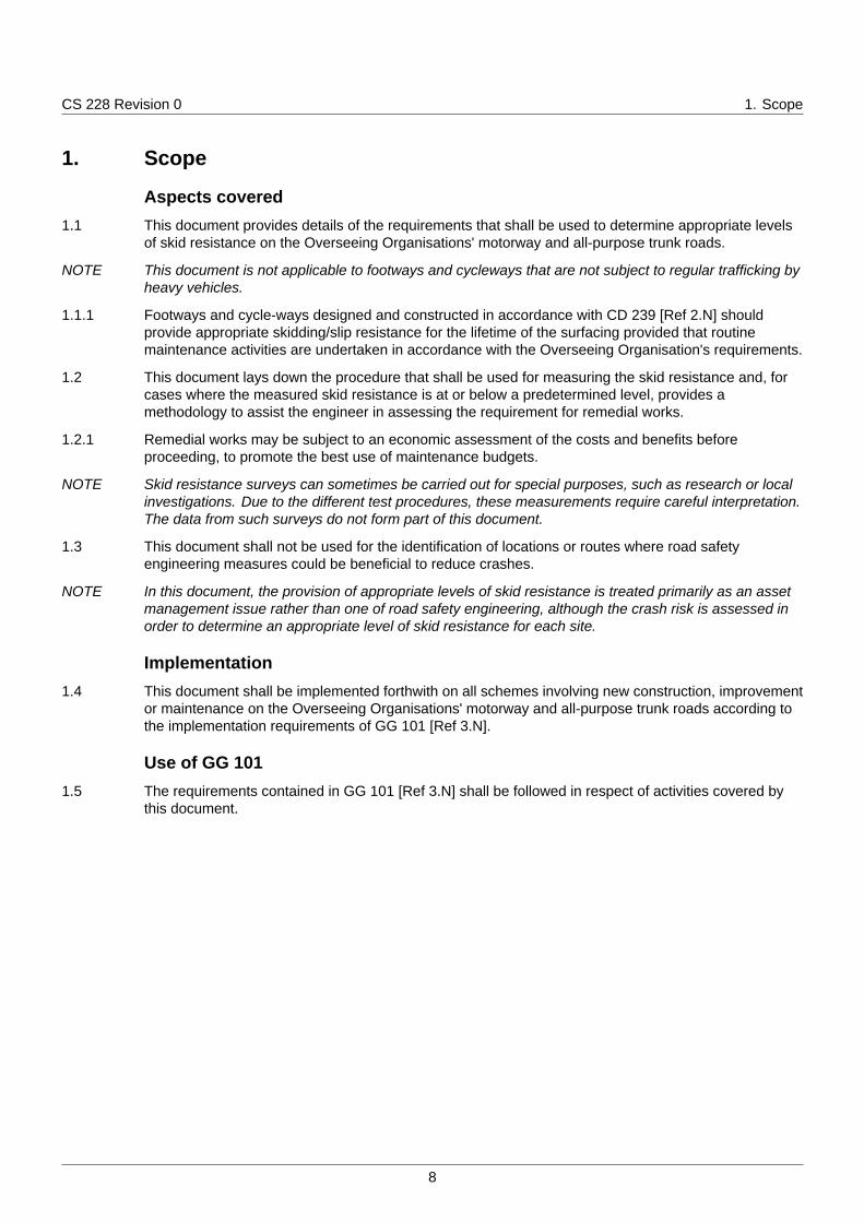
Figure 2.1 Overview of the operation of this document
2.2 Routine measurements of skid resistance shall be made using sideway-force coefficient routineinvestigation machines and processed to derive Characteristic Skid Coefficient (CSC) values inaccordance with Section 3.
10

CS 228 Revision 0 2. Operation
NOTE The CSC is an estimate of the underlying skid resistance once the effect of seasonal variation hasbeen taken into account. This value can be taken to represent the degree to which the road surfacehas become polished under the action of traffic.
2.3 On receipt of processed survey data, the CSC values shall be compared with the predeterminedInvestigatory Levels (ILs), to identify lengths of road where the skid resistance is at or below theInvestigatory Level.
NOTE Investigatory Levels represent a limit, above which the skid resistance is considered to be satisfactorybut at or below which the road is judged to require an investigation of the skid resistance requirements.Site categories are assigned based on broad features of the road type and geometry plus specificfeatures of the individual site. Investigatory Levels are assigned according to the perceived level of riskwithin each site category. Investigatory Levels can be reviewed on a rolling programme, to ensure thatchanges in the network are identified, local experience is applied and consistency is achieved. Theprocess for setting Investigatory Levels and the normal range of Investigatory Levels for each sitecategory are described in Section 4.
2.4 Wherever the CSC is at or below the assigned Investigatory Level an investigation shall be carried outto determine whether treatment to improve the skid resistance is required or whether some other actionis required.
NOTE The investigation process is described in Sections 5 and 6. The decision on whether treatment isnecessary is unlikely to be clear-cut, but requires professional engineering judgement taking intoaccount local experience, the nature of the site, the condition of the road surfacing and the crashhistory for the previous three years.
2.4.1 If successive investigations show that treatment is not warranted at the current level of skid resistancethen the Investigatory Level may be lowered (within the constraints of Table 4.2 and sub-clause 4.2.3 ofthis document).
NOTE The processes of setting Investigatory Levels and undertaking investigations are complementary, sincelocal knowledge and experience gained through conducting detailed investigations can be used torefine the criteria for setting Investigatory Levels for similar types of site.
2.5 The priority for treatment for those lengths where an improvement in skid resistance is beingrecommended shall be established through the Overseeing Organisation's process for prioritisingmaintenance.
11

CS 228 Revision 0 3. Measurement of skid resistance
3. Measurement of skid resistance
Overview3.1 This section details the procedure that shall be followed for planning and conducting skid resistance
surveys and processing the data. The process is outlined in Figure 3.1.
12

CS 228 Revision 0 3. Measurement of skid resistance
Figure 3.1 Measurement of skid resistance
NOTE 1 The process is split into the following 6 steps.
1) determine the survey procedure;2) plan surveys;3) conduct surveys;
13

CS 228 Revision 0 3. Measurement of skid resistance
4) process survey data;5) check survey coverage;6) apply seasonal correction.
NOTE 2 The steps are detailed in turn below.
Determine the survey procedure3.2 The basis of this document is that the overall (summer) level of skid resistance shall be assessed
rather than using a single measurement. This overall level of skid resistance is referred to as theCharacteristic Skid Coefficient (CSC).
NOTE 1 The skid resistance of road surfaces can fluctuate within a year and between successive years, whilemaintaining a similar general level over a longer period of time. By smoothing these fluctuationscaused by seasonal effects, sites exhibiting lower skid resistance can be identified more accurately.
NOTE 2 The way in which surveys are planned and how seasonal variation is accounted for is provided in theNational Application Annexes for each Overseeing Organisation.
3.3 Prior to the survey season, the network to be surveyed, the survey period, the test lane, the surveystrategy and the method and/or the accuracy of location referencing required shall be established withthe agreement of the Overseeing Organisation.
3.4 Measurements for monitoring the in-service skid resistance of motorway and all-purpose trunk roadsshall be made with a sideway-force coefficient routine investigation machine that has been accreditedby the Overseeing Organisation for use on its network and not with other skid resistance measurementdevices.
NOTE Various types of equipment are available for measuring skid resistance. Work has been carried out thathas produced some correlations between devices. However, these equations are not robust enough toallow the machines to operate interchangeably.
Plan surveys3.5 The survey provider shall plan the survey routes.
3.6 Surveys shall be planned so that they will occur during the required survey period (early, middle or late)to allow for the determination of CSC values.
3.7 These survey periods shall be defined so that the low point in the summer occurs during the middleperiod, as shown in Figure 3.7.
Figure 3.7 Survey periods
3.8 The dates for the survey periods can differ for different geographic regions and shall be defined by theOverseeing Organisation.
14

CS 228 Revision 0 3. Measurement of skid resistance
NOTE In exceptional circumstances the Overseeing Organisation can extend the testing season beyond theseperiods. This can only be done if the general weather conditions in the area remain unchanged and ifno frosts or treatments to the road, such as gritting, have occurred.
Conduct surveys3.9 Survey contractors shall comply with the calibration and quality assurance detailed in British Standard
BS 7941-1 [Ref 4.N] and the "Accreditation and Quality Assurance of Sideway-Force Skid ResistanceSurvey Devices" document available on the UK Roads Liaison Group (UKRLG) website [Ref 1.N].
3.10 In each direction of travel, the lane carrying the greatest number of heavy vehicles shall be tested.
NOTE For most roads, this will be the leftmost permanent lane.
3.10.1 Additional lanes, including the hard shoulder for sections where the hard shoulder is opened to traffic,may be surveyed only if required by the Overseeing Organisation.
3.11 If it is necessary for the machine to deviate from the test line (e.g. to avoid a physical obstruction orsurface contamination such as mud, oil, grit etc.) the data shall be marked as invalid and subsequentlydiscarded.
3.11.1 Where it is necessary for the machine to deviate from the test line, the invalid length should beresurveyed at a later date but still within the required survey period.
3.12 For the testing of roundabouts, after entering a roundabout a minimum of one complete circuit shall betested.
NOTE Ensuring that a complete circuit is surveyed can require the machine to complete more than onerevolution of the roundabout.
3.12.1 Where safe to do so, the preferred test line on roundabouts should be the outermost lane.
3.12.2 On multiple lane roundabouts with lane markings for different routes, it may be necessary to test analternative lane to avoid conflict with other traffic.
NOTE Roundabouts can present practical problems regarding potential traffic conflicts and testing speed.They range from small, mini-roundabouts to large grade-separated interchanges. Larger roundaboutscan have free-flowing traffic or traffic light controls at certain times of day.
3.13 Mini roundabouts and small island roundabouts that are physically too small to test as above shall betested as part of the main carriageway and do not need to be tested separately.
3.14 Measurements shall not be undertaken where the air temperature is below 5°C.
3.15 Testing shall be avoided in heavy rainfall or where there is standing water on the road surface.
NOTE Excess water on the surface can affect the drag forces at the tyre/road interface and influence themeasurements.
3.16 Where the posted speed limit is greater than 50mph, the target survey speed shall be 80km/h.
3.17 On all other roads, the target survey speed shall be 50km/h.
3.18 The machine driver shall maintain a vehicle speed as close to the target survey speed as possible.
3.19 The survey operator shall maintain a record of weather conditions that could influence the surveyresults, such as heavy rainfall or strong winds.
Process survey data3.20 On completion of the survey, the survey data shall be loaded into the Overseeing Organisation's
information management systems and aligned to the road network.
3.21 Readings for each 10m sub-section collected within the speed range 25 to 85km/h shall be corrected toa speed of 50km/h using the following equation:
15

CS 228 Revision 0 3. Measurement of skid resistance
Equation 3.21 To correct test reading speed to 50km/h for each sub-section
SR(50) = SR(s)× −0.0152× s2 + 4.77× s+ 799
1000
NOTE 1 Where: SR(50) is the value of SR(s) corrected to 50km/h
NOTE 2 SR(s) is the Sideways-Force Coefficient, measured at test speed s, multiplied by 100. This term isdefined further in BS 7941-1 [Ref 4.N].
3.22 Temperature correction shall not be applied.
3.23 SC values shall be calculated for each 10m sub-section for which a valid SR(s) value is available usingthe following equation:
Equation 3.23 To calculate SC values using a valid SR(s) value for sub-sections
SC =
(SR(50)100
)× Index of SFC
NOTE The Index of SFC (Sideways Force Coefficient) is currently 0.78.
Check survey coverage3.24 The survey machine operator shall produce a survey coverage report detailing the network that was to
be surveyed, lengths with missing or invalid data, and an explanation for the missing or invalid data.
Apply seasonal correction3.25 Once the data have been loaded and checked, the seasonally corrected CSC values shall be
determined from the SC values following the method appropriate to the survey strategy, as described inthe National Application Annexes.
16

CS 228 Revision 0 4. Setting the investigatory level
4. Setting the investigatory level
Overview4.1 The process that shall be followed for reviewing and assigning site categories and investigatory levels
is outlined in Figure 4.1.
Figure 4.1 Setting the investigatory level
17

CS 228 Revision 0 4. Setting the investigatory level
NOTE The process is split into the following 3 steps.
1) allocate site category and IL;2) identify sections for review;3) record updated ILs and review date.
Allocate site category and investigatory level4.2 An investigatory level (IL) shall be assigned for every part of the network, by determining the most
appropriate site category for each location and then selecting an appropriate IL from the rangeindicated in Table 4.2 for that site category.
Table 4.2 Site categories and investigatory levels
IL for CSC data (skid data speed corrected to 50km/h and seasonally corrected)
Site category and definition0.30 0.35 0.40 0.45 0.50 0.55 0.60 0.65
A Motorway LR ST
B Non-event carriageway with one-waytraffic
LR ST ST
C Non-event carriageway withtwo-way traffic LR ST ST
Q Approaches to and acrossminor and major junctions,approaches to roundabouts andtraffic signals (see 4.5)
ST ST ST
K Approaches to pedestriancrossings and other high risksituations (see 4.5)
ST ST
R Roundabout ST ST
G1 Gradient 5-10%, longer than50m (see 4.6) ST ST
G2 Gradient >10%, longer than50m (see 4.6) LR ST ST
S1 Bend radius <500m –carriageway with one-waytraffic (see 4.7 and 4.9)
ST ST
S2 Bend radius <500m –carriageway with two-waytraffic (see 4.8 and 4.10)
LR ST ST
NOTE 1 Sites with the same site category can have different levels of risk of skidding crashes. There istherefore the flexibility to set different ILs for different sites within the same category.
NOTE 2 This allows sites where the risk of skidding crashes is potentially higher to have a higher IL andpossibly be treated to maintain a higher level of skid resistance.
NOTE 3 The objective of setting an IL is to assign a level of skid resistance appropriate for the risk on the site, ator below which further investigation is required to evaluate the site specific risks in more detail.
18

CS 228 Revision 0 4. Setting the investigatory level
NOTE 4 Advice for selecting an appropriate IL is provided in Appendix A. The range of ILs for each site categoryhas been developed as a result of UK research studies on motorway and all-purpose trunk roads andreflects the variation in crash risk within a site category.
4.2.1 'ST' in cells within Table 4.2 indicates the range of ILs that should generally be used for roads carryingsignificant levels of traffic.
4.2.2 'LR' in cells indicates a lower IL that may be appropriate in lower risk situations, such as low trafficlevels or where the risks present are mitigated by other means, providing this has been confirmed bythe crash history.
4.2.3 Exceptionally, an IL higher or lower than those indicated in Table 4.2 may be assigned if justified by theobserved crash record and local risk assessment.
4.3 If more than one site category is appropriate then the site category with the highest recommended ILshall be selected.
4.4 If the highest recommended IL for the site categories are the same then the category highest up thetable shall be selected (A being the highest on the table and S2 the lowest).
4.5 ILs for site categories Q and K shall be based on the 50m approach to the feature and, in the case ofapproach to junctions, through to the extent of the junction.
4.5.1 The approach length may be extended when justified by local site characteristics.
4.6 Categories G1 and G2 shall not be applied to uphill gradients on carriageways with one-way traffic.
4.7 Category S1 shall be applied to all bends on carriageways with one-way traffic where the radius ofcurvature is <100m.
4.8 Category S2 shall be applied to all bends on carriageways with two-way traffic where the radius ofcurvature is <100m.
4.9 Category S1 shall be applied to bends on carriageways with one-way traffic with a radius of curvature ≥100m but <500m where the speed limit is ≥ 50mph.
4.10 Category S2 shall be applied to bends on carriageways with two-way traffic with a radius of curvature ≥100m but <500m where the speed limit is ≥ 50mph.
4.11 The site category and IL applied to a length shall be applied to all lanes of the carriageway that havetraffic running in the same direction.
4.11.1 All lanes of the carriageway (with the same direction of traffic) should be included when identifying whatsite category and IL will be applied. This includes the hard shoulder where hard shoulder running isimplemented.
4.12 The site category and IL information shall be recorded together with the date of assessment.
Identify sections for review4.13 A review of the IL shall be carried out when a significant change to the network is made, for example
changes to the road layout.
4.14 A procedure shall be put in place for reviewing the IL at least every three years.
NOTE The review of the IL can be done by reviewing one third of the network each year or all of the networkevery three years.
4.15 Lengths with missing IL data, or where the IL lies outside the range specified in Table 4.2, shall beincluded in each review.
Record updated ILs and review date4.16 The sections reviewed shall be recorded, together with the review date and any changes to the site
categories and ILs.
19

CS 228 Revision 0 5. Initial investigation
5. Initial investigation
Overview5.1 The process that shall be followed for the initial investigation is outlined in Figure 5.1.
Figure 5.1 Initial investigation
20

CS 228 Revision 0 5. Initial investigation
NOTE The process is split into the following steps.
1) identify sites at or below the IL;2) identify other sites requiring investigation;3) data validation;4) identify sites for detailed investigation.
5.2 All sites where the measured CSC is at or below the IL shall be investigated.
NOTE The objective is to determine whether a surface treatment is justified to reduce the risk of vehiclesskidding, whether some other form of action is required, or whether no action is currently required. If noaction is taken, sites will automatically be reviewed again following the next skid resistancemeasurement if they remain at or below the IL.
5.3 The investigation shall be undertaken in two stages: an initial investigation, described in this section, tocheck the data and assess the need for a detailed investigation and, secondly, a detailed investigationto assess the justification and priority for treatment, which is described in Section 6.
Identify sites at or below the IL5.4 The CSC value, calculated for the appropriate averaging length, shall be compared against the IL.
NOTE The appropriate averaging length is normally 100m or the length of a feature if it is shorter, except forroundabouts, where the averaging length is 10m.
5.5 The averaging length shall be truncated on any change of site category or IL.
5.5.1 Consequently, the averaging length will be shorter where the site category is less than 100m long or atthe end of a site category longer than 100m. Residual lengths less than 50% of a complete averaginglength may be appended to the penultimate length, if both the lengths have the same site category andIL.
NOTE If the skid resistance is close to the IL, successive 10m or 100m lengths can fall alternately above andbelow the IL. These lengths can be combined into a single site for investigation. The longer lengths arealso more robust for crash analysis. Subsequent detailed investigations can show that only part of thislength would require treatment.
Identify other sites requiring investigation5.6 An investigation shall also be carried out if, as a result of processes separate from those detailed in this
document, sites are identified where increased wet or skidding crash levels have been observed.
5.6.1 Examples of the processes referred to in clause 5.6 may include annual safety reports, policecomplaints, Managing Organisation observations and damage to roadside furniture.
Data validation5.7 Basic data validation checks shall be conducted for sites that have been identified as at or below the IL,
including confirmation that the IL has been assigned correctly in accordance with current guidance andthat the skid resistance recorded is within the normal range expected.
5.8 If the IL is incorrect then it shall be updated and recorded together with the date of the change.
5.8.1 If the skid resistance is above the revised IL then further investigation is unnecessary and the changeof IL should be recorded as the outcome of the investigation.
Identify sites for detailed investigation5.9 Sites at or below IL requiring detailed investigation shall be identified based on the site category, IL,
current skid resistance and observed crash history.
NOTE Further details of how to identify sites requiring detailed investigation are provided in the NationalApplication Annexes.
21

CS 228 Revision 0 5. Initial investigation
5.10 Sites identified for reasons other than skid resistance (see clause 5.6) shall always be subject to adetailed investigation.
5.11 On receipt of the CSC data, a list of sites requiring detailed investigation shall be produced.
22

CS 228 Revision 0 6. Detailed site investigation and prioritisatio...
6. Detailed site investigation and prioritisation6.1 A detailed investigation shall be carried out on sites identified from the outcome of the process in
Section 5.
23

CS 228 Revision 0 6. Detailed site investigation and prioritisatio...
Figure 6.1 Detailed site investigation and prioritisation
NOTE The process is outlined in Figure 6.1 and is split into the following four steps.
1) collate data;
24

CS 228 Revision 0 6. Detailed site investigation and prioritisatio...
2) plan investigations;3) carry out investigations;4) Prioritise and programme maintenance.
Collate data6.2 The data collected at the start of a detailed investigation shall include skid resistance, texture depth and
the most recent three years of crash data available.
NOTE For new construction or changes in layout, three years of relevant crash data are likely to not beavailable.
6.2.1 In cases where three years of crash data are not available, data since the date of construction orchange in layout should be used.
6.3 Skid resistance data at 10m intervals shall be obtained for bends and roundabouts.
NOTE Short lengths with low skid resistance could be hazardous for vehicles cornering and can be disguisedby averaging over a longer length.
6.3.1 Skid resistance data at 10m intervals should also be obtained if the condition of the surfacing materialis known to be variable over local areas.
6.3.2 If the site has poor transverse or longitudinal evenness, or bends or gradients, data for these featuresshould be obtained.
NOTE In some instances these data can assist in checking whether the site category and/or InvestigatoryLevel are correct or need amending.
6.3.3 Information on the date of the last surface treatment may also be relevant to the investigation and theinterpretation of collision data.
6.4 For each site, the relevant data shall be collated to show the location of lengths with poor surfacecondition relative to the location of previous crashes and features such as bends and junctions.
6.4.1 This relevant data may be collated as strip maps, GIS mapping or spreadsheets.
6.4.2 The location of crashes occurring in wet conditions, irrespective of whether skidding was reported,should be identified specifically.
6.4.3 Given the limited accuracy of locating accident positions, it may be assumed for the purpose of thedetailed investigation that the position of a crash coincides with the location of poor surface condition ifit occurred within 200m.
6.5 The overall crash risk shall be calculated for the site for comparison with control data.
6.5.1 The crash risk should be calculated as the total number of crashes per 108vehicle-km, if traffic data areavailable, or otherwise as the total number of crashes per year, per 100 km.
6.6 For this calculation the choice of whether to use carriageway length or route length, and the choice ofunits (km or miles) shall be consistent with the method used for the calculation of control data.
Plan investigations6.7 Greater priority shall be given to completing investigations for sites that are substantially below the IL or
where the crash history indicates that there is a risk of wet skidding crashes occurring.
6.7.1 Investigations should be planned primarily to maximise efficiency.
6.7.2 A physical visit to the site should be made.
NOTE Different investigation methods can be used, with differing advantages:
1) on foot (this allows the condition of the road to be observed in detail);
25

CS 228 Revision 0 6. Detailed site investigation and prioritisatio...
2) from a parked or moving vehicle (this allows the pattern of traffic movement and speed to beobserved during the visit);
3) from recent local knowledge of the site (this can provide a more general knowledge of the roadusage under a wider range of traffic, weather and lighting conditions);
4) from video records and maps. Maps cannot be used in isolation as they do not show obstructions tovisibility, drainage issues, field accesses, hidden dips, etc.
Carry out site investigations6.8 Site investigations shall determine whether treatment to improve the skid resistance is required or
whether some other action, including no action, is required.
6.8.1 The full carriageway width should be included in the investigation, that is all lanes of a dual carriagewayand both directions of a single carriageway.
NOTE 1 Skid resistance and texture depth are generally measured in the nearside wheel track in lane one. If,during a site investigation, the rest of the pavement is not visually consistent then it is possible that theskid resistance of the rest of the lane or other lanes can be lower than the line tested.
NOTE 2 Guidance for the assessment of texture depth is given in HD 30 [Ref 1.I].
NOTE 3 If a site contains a sharp bend to the left in combination with traffic braking or accelerating then theoffside wheel path can become more polished and the CSC can be up to 0.05 units lower than in thenearside wheel path.
6.8.2 If the pavement is not visually consistent, it may be necessary to carry out additional surveys toinvestigate potential variations in skid resistance.
6.8.3 All junction approaches within the site should also be investigated to determine whether the advancesigning/alignment is appropriate or could be improved.
6.8.4 The investigation should determine if the skid resistance is likely to be representative for the site.
6.8.5 In particular very low values of skid resistance should be viewed with caution.
NOTE Localised reduction in the skid resistance can be caused by contamination or by flushing of the binderto the surface. Alternatively, it is possible that there has been an error in the survey. In this case, thedata can be compared to data measured in previous years and also with adjacent lengths with thesame surfacing material, to determine if the skid resistance is representative of the condition of thesurfacing material.
6.9 If it is determined that the reduction in skid resistance is temporary and not representative for the site,then this shall be recorded with reasons.
6.9.1 Further investigation is not needed at determination that the reduction in skid resistance is temporaryand not representative for the site time, but if subsequent surveys continue to appear unrepresentativethen the causes should be investigated.
6.10 As a result of the detailed site investigation, a clear recommendation shall be recorded of the actions tobe taken (including if no immediate action is required).
NOTE An example template of a site investigation form is given in Appendix B.
6.10.1 Treatment to improve the skid resistance should be recommended if, taking into account the nature ofthe site and the observed crash history, it is likely to reduce the risk of crashes in wet conditions.
NOTE Based on knowledge of skid resistance and crash risk trends, sites that can be recommended fortreatment include locations where the position of crashes in wet conditions (whether or not skiddingwas reported) appears to be linked to surface condition, or where the overall crash risk is higher thanaverage when compared with suitable control data.
6.10.2 The Overseeing Organisation may be referred to for the provision of appropriate control data for thepurpose of making this assessment.
26

CS 228 Revision 0 6. Detailed site investigation and prioritisatio...
6.10.3 For sites where neither of the above conditions apply (see sub-clause 6.10.1), treatment should berecommended if the skid resistance, combined with the nature of the individual site, suggest that theobserved crash count underestimates the actual level of risk.
NOTE In such cases, preventive treatment can be justified to pre-empt a potential increase in crashes.
6.10.4 If treatment is only required on part of the site then those lengths should be clearly identified.
6.11 If the site investigation identifies any characteristic of the site or road-user behaviour that suggests otherroad safety engineering measures could be appropriate, then persons with relevant local experience,such as the person locally responsible for crash investigation and prevention, shall be notified.
6.12 If the site investigation identifies requirements for additional routine highway maintenance, such assweeping, renewal of markings etc. then persons with relevant local experience, such as the personlocally responsible for routine maintenance shall be notified.
6.13 If there is no justification for treatment then no further action shall be required.
NOTE If the site remains below the Investigatory Level after the next measurement of skid resistance then itwill automatically become subject to a further investigation.
6.13.1 If the skid resistance and crash pattern of a site at or below the IL have remained stable for more thanthree years, then the IL may be lowered by 0.05 units CSC providing it remains within the range of ILsspecified in Table 4.2.
6.14 The results of the detailed site investigation shall be documented and retained together with the identityof the assessor and other parties consulted.
Maintenance prioritisation and programming6.15 Budgeting and programming issues will influence when the treatments are carried out and this process
shall be managed through the Overseeing Organisation's process for prioritising maintenance.
27

CS 228 Revision 0 7. Use of slippery road warning signs
7. Use of slippery road warning signs
Overview7.1 The process that shall be followed for erecting and managing slippery road warning signs as part of this
document is outlined in Figure 7.1.
28
CS 228 Revision 0 7. Use of slippery road warning signs
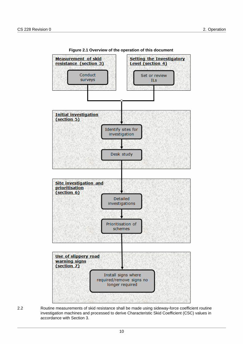
Figure 7.1 Use of slippery road warning signs
NOTE The process is split into the following three steps:
1) determine locations requiring warning signs;
29

CS 228 Revision 0 7. Use of slippery road warning signs
2) review locations of existing signs;3) install /amend /remove signs as necessary.
Determine locations requiring warning signs7.2 Once the locations of sites requiring warning signs have been identified a schedule for warning signs
shall be produced.
NOTE Details of which sites require warning signs are provided in the National Application Annexes.
Review locations of existing signs7.3 The skid resistance at the location of all existing slippery road warning signs shall be reviewed to
determine whether the sign is still needed.
7.3.1 The review of the need for existing slippery road warning signs should occur annually.
7.4 Once the review is completed the schedule for warning signs shall be updated to include the signswhich require removal.
Install / remove signs as necessary7.5 Warning signs shall be installed at sites where the need for them has been identified.
7.5.1 Short individual lengths requiring warning signs should be merged if they are separated by less than1km.
7.6 Warning signs shall then be removed after treatment has been applied.
7.7 The slippery roads warning sign (Diagram 557) in conjunction with an appropriate supplementary plate(Diagram 570) must be used in accordance with the TSRGD SI2016 No.362 2016 [Ref 5.N] andChapter 4 of the Traffic Signs Manual TSM Chapter 4 [Ref 6.N].
7.8 For the purpose of legal proceedings it is essential that records of the erection and removal of slipperyroad warning signs shall be kept, including works orders issued and inventories.
7.9 A visual inspection of the site shall be made after the signs are erected to confirm that they have beenerected and correctly placed.
7.10 A record of this observation shall be made and retained.
30

CS 228 Revision 0 8. Normative references
8. Normative referencesThe following documents, in whole or in part, are normative references for this document and areindispensable for its application. For dated references, only the edition cited applies. For undatedreferences, the latest edition of the referenced document (including any amendments) applies.
Ref 1.N UK Roads Liaison Group. TRL on behalf of Highways England. 'Accreditation andQuality Assurance of Sideways Force Skid Resistance Survey Devices' , 2016
Ref 2.N Highways England. CD 239, 'Footway and Cycleway Pavement Design'
Ref 3.N Highways England. GG 101, 'Introduction to the Design Manual for Roads andBridges'
Ref 4.N BSI. BS 7941-1, 'Methods for measuring skid resistance of pavement surfaces.Sideway-force coefficient routine investigation machine'
Ref 5.N HM Gov. TSRGD SI2016 No.362, 'The Traffic Signs Regulations and GeneralDirections' , 2016
Ref 6.N The Stationery Office . TSM Chapter 4, 'Traffic Signs Manual Chapter 4 - WarningSigns'
31

CS 228 Revision 0 9. Informative references
9. Informative referencesThe following documents are informative references for this document and provide supportinginformation.
Ref 1.I Highways England. HD 30, 'Pavement maintenance assessment procedure'
32

CS 228 Revision 0 Appendix A. Application of site categories and Investiga...
Appendix A. Application of site categories and Investigatory Levels
A1 OverviewThis Appendix provides detailed guidance on the selection of appropriate site categories and ILs fromthe range in Table 4.2. These are then followed by some examples. Where appropriate, supplementaryguidance is provided within the relevant National Application Annex.
Lengths with no specific risk of skidding crashes should be assigned the lowest IL with 'ST' cellindication from the appropriate site category. Where identified risks exist, a higher IL should beselected from within the range. The guidance given in this section is not exhaustive and thereforejudgement of the risks specific to each location should be exercised.
Additional information, such as safety reports and congestion reports may be useful when setting sitecategories and the IL. They may be used to help identify higher risk situations and where queuing islikely.
A2 Category A: MotorwayThis site category should be used for all sections of main carriageway that meet motorway standards ofgeometric design, including merging and diverging areas of the carriageway. Motorway slips roadsshould not have category A applied but instead should have category B (or the appropriate eventcategory) applied.
If the motorway length under consideration does not meet motorway standards of geometric designthen the length should be treated as a carriageway with one-way traffic (either event or non-eventdepending on the situation).
An IL of 0.35 should be appropriate in almost all circumstances.
The IL can be changed to 0.30 in exceptional cases if, following a detailed site investigation, it is clearthat the crash risk associated with a skid resistance below 0.35 is low.
A3 Category B: Non-event carriageway with one-way trafficThis site category should be used for all non-motorway dual carriageways and other lengths withone-way traffic, including motorway slip roads. Note that other events on lengths with one-way traffic,such as approaches to roundabouts/junctions, bends or gradients should be considered andcategorised accordingly.
At junctions, category B should be used for areas where traffic merges or diverges if:
1) the junction layout allows traffic leaving or joining the mainline to match the speed of the mainlinetraffic; and
2) there is adequate taper length for merging to occur.
For category B an IL of 0.35 should be appropriate in most circumstances.
The IL can be reduced to 0.30 only following a detailed site investigation and it is clear that the crashrisk associated with a skid resistance below 0.35 is low.
The IL should be increased to 0.40 for:
1) areas where pedestrians or other vulnerable road users are common but category K is notappropriate;
2) hazards where the speed limit is 50mph or above and where category Q is not appropriate, including:
a) junctions where the geometry does not justify using category Q;b) bus stops, laybys, etc;c) other accesses, e.g. private roads/drives, depending on the volume of traffic and vehicle types
using the access;
33
CS 228 Revision 0 Appendix A. Application of site categories and Investiga...
3) bends on roads with a radius >100m and a speed limit below 50mph if they present a particularhazard in spite of the lower speed;
4) uphill sections that give rise to a speed differential between vehicles that could result in increasedrisk;
5) the approach to the end of a dual carriageway where a lane drop occurs.
A4 Category C: Non-event carriageway with two-way trafficThis site category should be used for all non-event carriageway sections with two-way traffic.
At junctions, category C should be used for areas where traffic merges or diverges if:
1) the junction layout allows traffic leaving or joining the mainline to match the speed of the mainlinetraffic; and
2) there is adequate taper length for merging to occur without the mainline being forced into avoidingaction.
An IL of 0.40 should be appropriate in most circumstances.
The IL can be reduced to 0.35 following a detailed site investigation.
The IL should be increased to 0.45 for:
1) areas where pedestrians or other vulnerable road users are common but category K is notappropriate;
2) hazards where the speed limit is 50mph or above (over the braking area) and where category Q isnot appropriate, including:
a) junctions where the geometry does not justify using category Q;b) bus stops, lay-bys, etc;c) other accesses, e.g. private roads, depending on the volume of traffic and vehicle types using
the access;
3) bends on roads with a radius >100m and a speed limit below 50mph if they present a particularhazard in spite of the lower speed;
4) uphill sections that give rise to a speed differential between vehicles that could result in increasedrisk, but category G1 or G2 is not appropriate.
A5 Category Q: Approaches to and across minor and major junctions, approachesto roundabouts and traffic signalsThis site category should be used for:
1) major / minor priority junctions;
2) other significant accesses;
3) approaches to roundabouts and traffic signals (except for high risk circumstances such aspedestrian crossings etc.).
If the junction design and traffic volume allows the traffic to merge with / diverge from the mainline trafficwithout changing speed, this site category should not be used (use category B or C instead).
A5.1 Approaches to junctions:
For the purposes of this document, roads involved in a junction are split into two types, the major roadand the minor road(s). The major road is the road where traffic has permanent priority. The minorroad(s) are where traffic is required to give way.
Drivers on the major road have permanent priority and are not expecting to give way, but may have tobrake sharply if a vehicle emerges unexpectedly from the minor road or turns right across their path.Factors to consider are:
34

CS 228 Revision 0 Appendix A. Application of site categories and Investiga...
1) right turning vehicles from a minor road are at risk of a side impact with traffic on the major road, andthe outcome of this type of crash is likely to be severe;
2) the risks increase where the speed of traffic joining or leaving the main carriageway differs greatlyfrom those continuing straight on. This is heavily influenced by the taper length, provision ofdedicated lanes for right-turning traffic, etc.
On the minor road, the risk of having to brake unexpectedly is lower since the need to give way isindicated clearly in advance of the junction.
On the major road site category Q should be applied to the 50m approach (in the direction of travel) tothe junction and across the extent of the junction. For roads with a speed limit of 50mph or above,consider extending the approach distance, depending on the risk of traffic having to brake unexpectedly.
For major roads with two-way traffic, consider the two directions separately to determine the overallextent of the site category. The two directions should be assigned the site category and ILindependently so that site category Q is not applied on the length following a junction.
For major roads, an IL of 0.45 should be used if:
1) the speed limit is below 50mph;
2) the speed limit is 50mph or above but the traffic volume and speed differential between the majorand minor traffic streams results in an acceptably low risk.
For major roads, an IL of 0.50 should be used if the speed limit is 50mph or above and:
1) the combination of speed differential and traffic volume result in a moderate level of risk;
2) sight lines on the minor road are poor, leading to the possibility of driver error;
3) right-turning traffic from the major road is not adequately catered for;
4) high levels of traffic on the mainline may induce drivers joining it to take risks when pulling out.
For major roads, an IL of 0.55 should be used only in exceptional circumstances where the risk is high.Consider whether the high risk could be mitigated more appropriately by other means.
On the minor road, site category Q should be applied to the 50m approach to the stop/give way line.Extend the distance, if necessary, to take into account likely queues.
For minor roads, an IL of 0.45 should be used in most circumstances.
The IL should be increased for minor roads to 0.50 if the sight lines (on the minor road) approaching thejunction are poor, leading to the possibility of a driver having to brake suddenly.
Where the volume of traffic using the access warrants it, other significant accesses (petrol stations,superstores etc.) should be treated as for major/minor priority junctions, above. If the volume of trafficis low, use the appropriate non-event categories instead.
A5.2 Approaches to roundabouts and traffic signals:
Site category Q should be applied to the 50m approach to the stop/give-way line. Extend the distance,as necessary, to take into account likely regular queuing.
This site category should not be used for signal-controlled pedestrian crossings or for other high risksituations. Category K should be used instead.
An IL of 0.45 should be used if the speed limit is below 50mph, or if there is a higher speed limit butactual traffic speeds are low, e.g. because the road layout does not lend itself to higher speed.
An IL of 0.50 should be used if the speed limit is 50mph or above unless actual traffic speeds are low.
An IL of 0.55 should be used only in exceptional circumstances where the risk is high. Considerwhether the high risk could be mitigated more appropriately by other means.
35

CS 228 Revision 0 Appendix A. Application of site categories and Investiga...
A6 Category K: Approaches to pedestrian crossings and other high risk situationsSite category K should be applied where the consequences of a crash are likely to be severe, including:
1) signal controlled pedestrian crossings and zebra crossings;
2) railway crossings;
3) other situations where there is both a likelihood of vulnerable users in the road and a high risk ofinjury in the event of a crash.
Site category K should be applied for the 50m approach to the event. Consider extending this distancefor roads with speed limits of 50mph or above, depending on the likelihood of traffic having to brakeunexpectedly.
An IL of 0.50 should be appropriate in most circumstances.
The IL should be increased to 0.55 where there is reason to believe pedestrians or other vulnerableroad users may misjudge the speed of oncoming traffic, such situations include:
1) near schools or other facilities for children;
2) near public houses;
3) where the speed of approaching traffic is high.
A7 Category R: RoundaboutSite category R should be used for roundabout circulation areas, including approaches to traffic lightson roundabouts. If there are specific, high-risk situations then category K should be used. Miniroundabouts should be excluded from this site category; in this instance category Q should be appliedto the approach and across the mini-roundabout.
An IL of 0.45 should be appropriate in most circumstances.
The IL should be increased to 0.50 under the following circumstances:
1) high speed of circulating traffic;
2) high incidence of cyclists or motorcyclists;
3) absence of signalised control on roundabouts at grade separated interchanges.
A8 Category G1: Gradient 5-10% longer than 50mSite category G1 should be used on carriageways with two-way traffic, for lengths of at least 50m withan average uphill or downhill gradient of between 5 and 10%.
Site category G1 should be used on carriageways with one-way traffic, for lengths of at least 50m withan average downhill gradient of between 5 and 10%.
This assessment may be based on 10m gradient data from traffic-speed surveys or from accuratetopographical survey data when available.
An IL of 0.45 should be appropriate in most circumstances.
The IL should be raised to 0.50 if there are other risk factors also present such as poor visibility etc.
A9 Category G2: Gradient >10% longer than 50mSite category G2 should be used on carriageways with two-way traffic, for lengths of at least 50m withan average uphill or downhill gradient greater than 10%.
Site category G2 should be used on carriageways with one-way traffic, for lengths of at least 50m withan average downhill gradient of 10% of higher.
This assessment may be based on 10m gradient data from traffic-speed surveys or from accuratetopographical survey data when available
36

CS 228 Revision 0 Appendix A. Application of site categories and Investiga...
An IL of 0.50 should be appropriate in most circumstances.
The IL can be reduced to 0.45 only after a detailed site investigation.
The IL should be raised to 0.55 if there are other risk factors also present such as poor visibility etc.
A10 Category S1/S2: Bend radius < 500mThis Site category should be used for bends on carriageways with one-way traffic (category S1) and oncarriageways with two-way traffic (category S2).
For bends with radii between 100m and 500m the S1 and S2 categories should only be applied wherethe speed limit is 50mph or above. For roads with lower speed limits, use the non-event site category Bor C. For bends that have radii less than 100m, S1 and S2 should apply at all speeds.
This category should not generally be used for:
1) short lengths, for example less than 100m, with a radius of curvature between 250m and 500m;
2) roundabout exits.
The site category should be extended upstream and downstream to where the radius of the road hasexceeded 500m or 100m for bend radii where S1 or S2 is used at speeds lower than 50mph.
The lower, cells with 'ST' indication for each category should be appropriate in most circumstances (ILof 0.45 for category S1, or 0.50 for category S2).
The IL should be raised if there are other risk factors also present (IL of 0.50 for category S1, or 0.55for category S2), or particular potential for loss of control, including if:
1) the geometry of the bend is particularly hazardous, taking into account the traffic speed;
2) adverse camber is present.
For category S2, the IL can be reduced to 0.45 only after a detailed site investigation.
This assessment may be based on 10m curvature data from traffic-speed surveys, drawings or fromaccurate topographical survey data when available.
A11 ExamplesA11.1 Example: Motorway grade separated junction
For generic motorway grade separated junctions there are four different site categories in effect, asdescribed below and shown in Figure A.1. In some cases other site categories may also be requireddue to other events occurring in the vicinity.
37

CS 228 Revision 0 Appendix A. Application of site categories and Investiga...
Figure A.1 Site categories for a typical motorway grade separated junction layout
The main carriageway should have category A applied to its whole length (if appropriate to itsgeometry/layout). The off slip should have category B applied for the majority of its length with categoryQ applied to the last 50m (length of Q to be extended if queues likely).The on slip should have categoryB applied to its whole length unless other events for the site take precedence (e.g. high gradient or tightbend). The roundabout should have category R applied to its whole length.
A11.2 Example: T-junction on a single carriageway
For a T-junction on a single carriageway there are two different site categories in effect, as describedbelow and shown in Figure A.2. In some cases other site categories may also be required due to otherevents occurring in the vicinity.
In the figure for this example the major road (where traffic has permanent priority) is the 'horizontal'road and the minor road (where traffic is required to give way) is the 'vertical' road.
38

CS 228 Revision 0 Appendix A. Application of site categories and Investiga...
Figure A.2 Site categories for junction approaches on a single carriageway
On the minor road a category of Q should be applied to the 50m approach to the junction. This lengthmay be extended if queuing is likely. The remaining length (including the lane with traffic moving awayfrom the junction) should be given a category of C.
On the major road a category of Q should be applied to the extent of the junction and the 50m leadingto the junction (in the direction of traffic on the major road) for both lanes. This length may be extendedif the risk of traffic having to brake unexpectedly is higher than usual. The remaining length of the majorroad should be given a category of C (if appropriate to the site geometry/layout).
A11.3 Example: Priority junction
For a priority junction between two single carriageways there are two different site categories in effect,as described below and shown in Figure A.3. In some cases other site categories may also be requireddue to other events occurring in the vicinity.
In the figure for this example the "major road" (where traffic has permanent priority) is the top part of the'horizontal' road (traffic moving from left to right) and the bottom part of the horizontal road (trafficmoving from right to left). The "minor roads" are the 'vertical' road and the turn lane of the horizontalroad. This example is assuming that right turns from the vertical road are prohibited.
39

CS 228 Revision 0 Appendix A. Application of site categories and Investiga...
Figure A.3 Site categories for a priority junction
The top part of the 'horizontal' road ("major road") should have a category of Q applied to the extent ofthe junction and the 50m leading to the junction (in the direction of traffic on the major road). Thislength may be extended if the risk of traffic having to brake unexpectedly is higher than usual. Theremainder of the top part of the horizontal road should have the appropriate non-event category applied(in this case C).
The turn lane ("minor road") should have a category of Q applied to the 50m approach to the give way.The bottom part of the 'horizontal' road ("major road") should have a category of Q applied to the 50mapproach to the start of the junction and for the extent of the junction. As the two lanes describedabove are running lanes from the same carriageway with traffic in the same direction, they should havethe same site category and IL applied along their coinciding length (see clause 4.9).
The 'vertical' road (one of the "minor roads") should have a category of Q applied to the 50-m approachto the junction. This length may be extended if queuing is likely. The remaining length (including thelane with traffic moving away from the junction) should have the appropriate non-event categoryapplied (in this case C).
A11.4 Example: Roundabout with a pedestrian crossing
For a roundabout with a pedestrian crossing on an approach or exit, there are four different sitecategories in effect (if all of the roads are single carriageway), as described below and shown in FigureA.4. In some cases other site categories may also be required due to other events occurring in thevicinity.
40

CS 228 Revision 0 Appendix A. Application of site categories and Investiga...
Figure A.4 Site categories for a roundabout with a pedestrian crossing
A site category of K should be applied to the 50m approach to the pedestrian crossing. This length maybe extended depending on the likelihood of traffic having to brake unexpectedly.
The roundabout should be assigned a category of R for its whole length. Note, if this was a signalisedroundabout, the roundabout would still be assigned a category of R for its whole length.
The approaches to the roundabout should all have category Q applied for the 50m approach. Thislength may be extended if queuing is likely. Also if the remaining distance between this category andthe crossing is small then this category may be extended back to the crossing.
The remaining lengths should have category C applied (if appropriate to its geometry/layout), as theyare all non-event carriageways with two-way traffic.
A11.5 Example: Signal controlled crossroads involving a dual carriageway road and a singlecarriageway road
For this type of crossroads there are four different site categories in effect, as described below andshown in Figure A.5. In some cases other site categories may also be required due to other eventsoccurring in the vicinity.
41
CS 228 Revision 0 Appendix A. Application of site categories and Investiga...
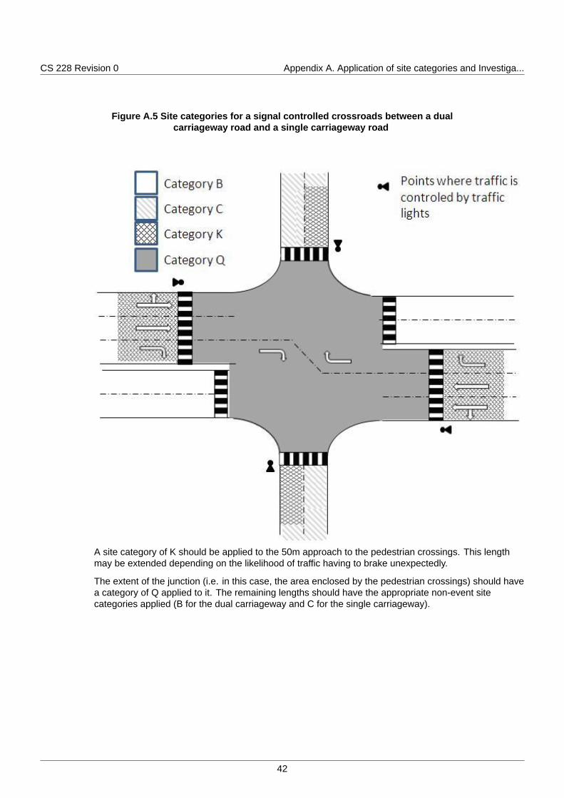
Figure A.5 Site categories for a signal controlled crossroads between a dualcarriageway road and a single carriageway road
A site category of K should be applied to the 50m approach to the pedestrian crossings. This lengthmay be extended depending on the likelihood of traffic having to brake unexpectedly.
The extent of the junction (i.e. in this case, the area enclosed by the pedestrian crossings) should havea category of Q applied to it. The remaining lengths should have the appropriate non-event sitecategories applied (B for the dual carriageway and C for the single carriageway).
42

CS 228 Revision 0 Appendix B. Site investigation report template
Appendix B. Site investigation report template
43

CS 228 Revision 0 Appendix B. Site investigation report template
Figure B.1 Site investigation report template
44
CS 228 Revision 0 Appendix B. Site investigation report template
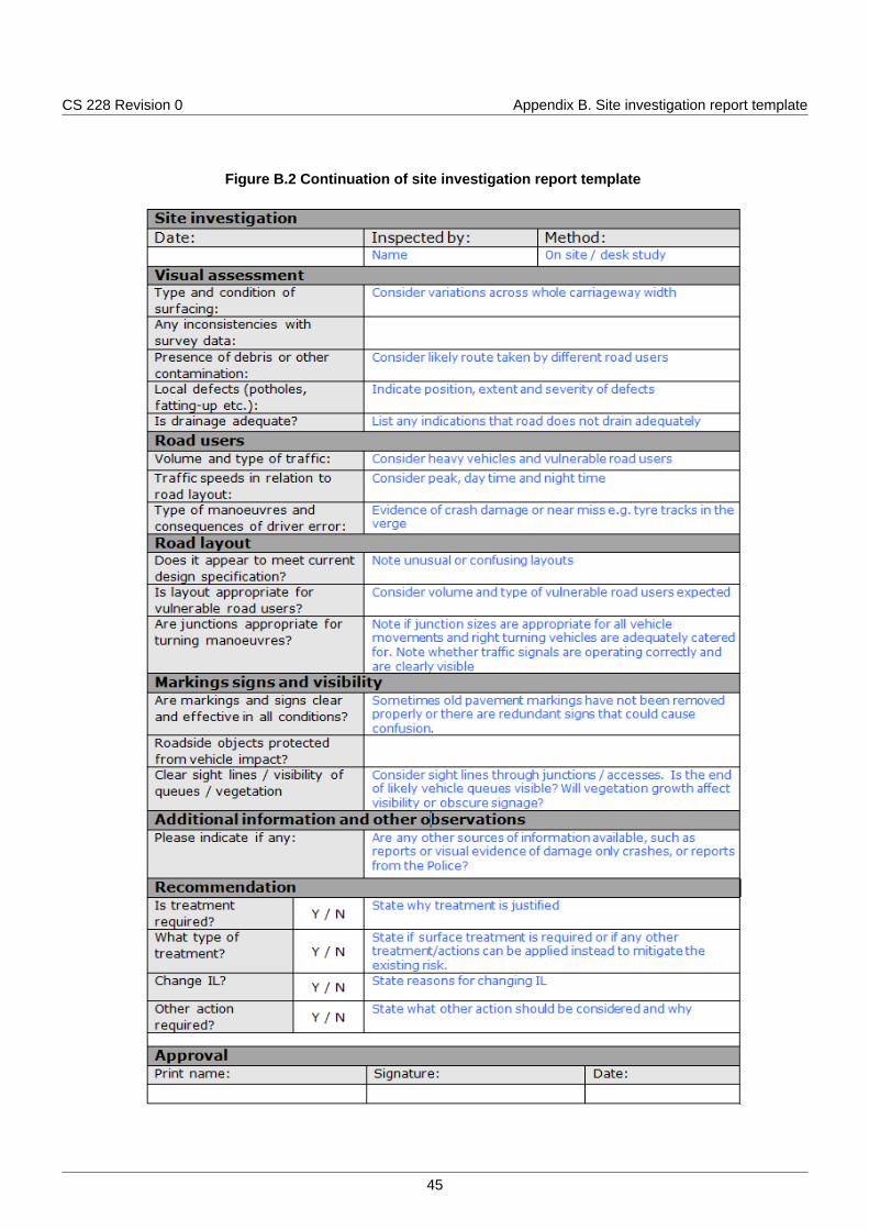
Figure B.2 Continuation of site investigation report template
45

© Crown copyright 2019.You may re-use this information (not including logos) free of charge in any format or medium, under the terms of the
Open Government Licence. To view this licence:visit www.nationalarchives.gov.uk/doc/open-government-licence/,
write to the Information Policy Team, The National Archives, Kew, London TW9 4DU,or email [email protected].

Design Manual for Roads and Bridges
PavementInspection & Assessment
CS 228England National Application Annex to CS 228Skidding resistance(formerly HD 28/15)
Revision 0
SummaryThis National Application Annex sets out the Highways England specific requirements onapplying seasonal correction to skid resistance measurements, the process for identifying sitesthat require a detailed investigation and for identifying sites where slippery road warning signsare required.
Feedback and EnquiriesUsers of this document are encouraged to raise any enquiries and/or provide feedback on the content and usageof this document to the dedicated Highways England team. The email address for all enquiries and feedback is:[email protected]
This is a controlled document.

CS 228 Revision 0 Contents
Contents
Release notes 2
Foreword 3Publishing information . . . . . . . . . . . . . . . . . . . . . . . . . . . . . . . . . . . . . . . . . . . . . . . . 3Contractual and legal considerations . . . . . . . . . . . . . . . . . . . . . . . . . . . . . . . . . . . . . . . . 3
Introduction 4Background . . . . . . . . . . . . . . . . . . . . . . . . . . . . . . . . . . . . . . . . . . . . . . . . . . . . . . 4Assumptions made in the preparation of this document . . . . . . . . . . . . . . . . . . . . . . . . . . . . . 4
Abbreviations 5
Terms and definitions 6
E/1. Single annual skid survey (SASS) approach to calculation of CSC 7Overview of SASS approach . . . . . . . . . . . . . . . . . . . . . . . . . . . . . . . . . . . . . . . . . . . . 7
E/2. Procedure for identifying sites requiring detailed investigation 9Highways England crash model . . . . . . . . . . . . . . . . . . . . . . . . . . . . . . . . . . . . . . . . . . . 9
E/3. Determining locations requiring warning signs 10
E/4. Normative references 11
E/5. Informative references 12
1

CS 228 Revision 0 Release notes
Release notesVersion Date Details of amendments0 Aug 2019 Highways England National Application Annex to CS 228.
2

CS 228 Revision 0 Foreword
Foreword
Publishing informationThis document is published by Highways England.
This document supersedes HD 28/15, which is withdrawn.
Contractual and legal considerationsThis document forms part of the works specification. It does not purport to include all the necessaryprovisions of a contract. Users are responsible for applying all appropriate documents applicable totheir contract.
3

CS 228 Revision 0 Introduction
Introduction
BackgroundThis National Application Annex gives the Highways England-specific requirements related to theapplication of seasonal correction to skid resistance measurements, the process for identifying sitesthat require a detailed investigation and the identification of sites where slippery road warning signs arerequired.
Assumptions made in the preparation of this documentThe assumptions made in GG 101 [Ref 1.N] apply to this document.
4

CS 228 Revision 0 Abbreviations
Abbreviations
AbbreviationsAbbreviation DefinitionCSC Characteristic Skid Coefficient. The SC value that has been corrected for seasonal
variations following the method appropriate to the survey strategy adopted by theOverseeing Organisation.
LECF Local Equilibrium Correction Factor
LESC Local Equilibrium SC
LMSC Local Mean SC
SASS Single Annual Skid Survey
SC A friction coefficient calculated from a sideways-force coefficient routineinvestigation machine reading, by application of a speed correction and Index ofSFC.
SFC Sideways Force Coefficient
5

CS 228 Revision 0 Terms and definitions
Terms and definitions
TermsTerm DefinitionIndex of SFC Index of Sideways Force Coefficient. A factor applied to relate the values given
by sideways-force coefficient routine investigation machines to historic values.
6
CS 228 Revision 0 E/1. Single annual skid survey (SASS) approach to ...
E/1. Single annual skid survey (SASS) approach to calculation of CSC
Overview of SASS approachE/1.1 The method shall use measurements from the preceding three years to characterise the long-term skid
resistance of the network.
E/1.2 The long-term value of skid resistance shall be used, with the mean network skid resistance in thecurrent year, to calculate a correction factor that is applied to the current year's data to make currentvalues consistent with the long-term average.
E/1.3 Sections which have had resurfacings carried out in the last three years shall be identified and removedfrom the calculation procedure for the correction factors.
NOTE The SASS approach takes account of yearly variation and therefore the calculations are affected bymaintenance carried out in the last three years.
E/1.4 Larger highway networks shall be split into smaller localities.
E/1.5 The correction factor shall be determined and applied separately within each locality.
NOTE The effect of seasonal variation will vary in different geographical areas (such as due to differentamounts of rainfall), therefore necessitating the need for a local approach.
E/1.6 The whole network shall be surveyed once during the test season in each year.
E/1.7 Surveys shall be planned such that in successive years each road length is tested in the early, middleand late parts of the season.
E/1.7.1 As a route tested in the early part of the season in year 1 could be tested in the late part of the seasonin year 2 and in the middle part of the season in year 3, in year four, it should be tested in the early partof the season again, and so forth.
E/1.8 Each site on the network shall be allocated to a locality by the Overseeing Organisation.
NOTE A locality is a collection of road sections or routes for which a correction factor can be determined.
E/1.9 A locality shall be small enough so that similar weather conditions would normally be experienced withinit and large enough so that a stable value can be calculated to represent the long-term skid resistance.
NOTE This approach is based on the assumption that the climatic effects leading to seasonal variation caninfluence all the roads in a local area in a similar way.
E/1.10 All the road sections within each locality shall be surveyed within the same part of the test season.
NOTE By surveying all road sections within a locality at the same time, this method can remove a componentof the within-year seasonal variation as well as the variation between years.
E/1.11 The local equilibrium correction factor (LECF) is the correction factor that shall be used within eachlocality to bring the current year data to a level consistent with the long-term average.
NOTE The LECF is calculated in three stages.
E/1.12 The local equilibrium SC (LESC) shall be determined to represent the average skid resistance level forthe locality over recent years.
NOTE The LESC is the average SC, calculated for all valid 10-m sub-section measurements in the definedlocality over the three years that precede the current testing season.
E/1.13 The LESC shall contain surveys from each of the three parts of the test season with validmeasurements being those that were made in the required part of the test season, on the required testline, and on road surfaces that were at least 12 months old at the time of testing.
E/1.13.1 As a consequence of Cl. E/1.12, if a length of road has been resurfaced within the last four years thenthat length should be excluded from the LECF calculation.
7

CS 228 Revision 0 E/1. Single annual skid survey (SASS) approach to ...
E/1.14 The Local Mean SC (LMSC) shall be determined for the current survey. The LMSC is the average of allvalid 10-m sub-sections in the locality in the current year survey.
E/1.15 The LECF shall be determined by dividing the LESC by the LMSC, that is:
Equation E/1.15 Calculation of LECF
LECF =LESC
LMSC
E/1.16 The CSC for each 10-m sub-section shall be determined by multiplying the corrected SC by the LECF.
8

CS 228 Revision 0 E/2. Procedure for identifying sites requiring det...
E/2. Procedure for identifying sites requiring detailed investigation
Highways England crash modelE/2.1 A crash model which has been developed for Highways England shall be used to identify sites requiring
detailed investigation on motorway and all-purpose trunk roads managed by Highways England.
NOTE 1 Further information about the crash model, its development and testing can be found in TRL reportCPR1308 2009 [Ref 1.I] and TRL report CPR921 2010 [Ref 2.I].
NOTE 2 The crash model can be obtained from Highways England.
NOTE 3 The crash model utilises crash trends (both rate and severity) from historic Highways England data topredict the expected crash saving from the application of a surface treatment. The model requires theinput of crash counts for the latest 3 years, CSC values and Site Category. It then produces a scorewhich can be used to identify if the site requires detailed investigation. The documentation suppliedwith the crash model gives guidance on the site scores that trigger a detailed site investigation.
E/2.2 Sites that have been identified for reasons other than skid resistance (see Cl. 5.6 of main document)shall not be removed by this process.
9

CS 228 Revision 0 E/3. Determining locations requiring warning signs
E/3. Determining locations requiring warning signsE/3.1 Sites which, as a result of a detailed investigation, have been identified as requiring treatment to
improve skid resistance shall have warning signs erected.
10

CS 228 Revision 0 E/4. Normative references
E/4. Normative referencesThe following documents, in whole or in part, are normative references for this document and areindispensable for its application. For dated references, only the edition cited applies. For undatedreferences, the latest edition of the referenced document (including any amendments) applies.
Ref 1.N Highways England. GG 101, 'Introduction to the Design Manual for Roads andBridges'
11

CS 228 Revision 0 E/5. Informative references
E/5. Informative referencesThe following documents are informative references for this document and provide supportinginformation.
Ref 1.I Transport Research Laboratory. Coyle F and Viner H. CPR1308, 'Accident model forprioristing treatments to improve road surface skid resistance' , 2009
Ref 2.I Transport Research Laboratory. Brittain S and Coyle F. CPR921, 'Development andtrial of procedures for identifying sites requiring a detailed skid resistanceinvestigation' , 2010
12

© Crown copyright 2019.You may re-use this information (not including logos) free of charge in any format or medium, under the terms of the
Open Government Licence. To view this licence:visit www.nationalarchives.gov.uk/doc/open-government-licence/,
write to the Information Policy Team, The National Archives, Kew, London TW9 4DU,or email [email protected].

Design Manual for Roads and Bridges
PavementInspection & Assessment
CS 228Northern Ireland National Application Annex toCS 228 Skidding resistance(formerly HD 28/15)
Revision 0
SummaryThis National Application Annex sets out the Department for Infrastructure Northern Irelandspecific requirements on applying seasonal correction to skid resistance measurements foridentifying sites where slippery road warning signs are required.
Feedback and EnquiriesUsers of this document are encouraged to raise any enquiries and/or provide feedback on the content and usage ofthis document to the dedicated team in the Department for Infrastructure, Northern Ireland. The email address for allenquiries and feedback is: [email protected]
This is a controlled document.
CS 228 Revision 0 Contents
Contents
Release notes 2
Foreword 3Publishing information . . . . . . . . . . . . . . . . . . . . . . . . . . . . . . . . . . . . . . . . . . . . . . . . 3Contractual and legal considerations . . . . . . . . . . . . . . . . . . . . . . . . . . . . . . . . . . . . . . . . 3
Introduction 4Background . . . . . . . . . . . . . . . . . . . . . . . . . . . . . . . . . . . . . . . . . . . . . . . . . . . . . . 4Assumptions made in the preparation of this document . . . . . . . . . . . . . . . . . . . . . . . . . . . . . 4
Abbreviations 5
Terms and definitions 6
NI/1. Benchmark sites approach to calculation of CSC 7Benchmark sites approach calculation procedure . . . . . . . . . . . . . . . . . . . . . . . . . . . . . . . . . 7
NI/2. Determining locations requiring warning signs 8
NI/3. Normative references 9
1

CS 228 Revision 0 Release notes
Release notesVersion Date Details of amendments0 Aug 2019 Department for Infrastructure Northern Ireland National Application Annex to
CS 228. A new National Application Annex under the DMRB 2020 programme.
2

CS 228 Revision 0 Foreword
Foreword
Publishing informationThis document is published by Highways England on behalf of the Department for Infrastructure,Northern Ireland.
This document supersedes HD 28/15, which is withdrawn.
Contractual and legal considerationsThis document forms part of the works specification. It does not purport to include all the necessaryprovisions of a contract. Users are responsible for applying all appropriate documents applicable totheir contract.
3

CS 228 Revision 0 Introduction
Introduction
BackgroundThis National Application Annex sets out the Department for Infrastructure Northern Ireland-specificrequirements on applying seasonal correction to skid resistance measurements and for identifying siteswhere slippery road warning signs are required.
Assumptions made in the preparation of this documentThe assumptions made in GG 101 [Ref 1.N] apply to this document.
4

CS 228 Revision 0 Abbreviations
Abbreviations
Abbreviations
Abbrevia-tions
Definition
CSC Characteristic Skid Coefficient. The SC value that has been corrected for seasonalvariations following the method appropriate to the survey strategy adopted by theOverseeing Organisation.
LECF Local Equilibrium Correction Factor
LESC Local Equilibrium SC
LMSC Local Mean SC
MSSC Mean Summer Skid Coefficient
MSCF Mean Summer Correction Factor
SCA friction coefficient calculated from a sideway-force coefficient routine investigationmachine reading, by application of a speed correction and Index of SFC.
5

CS 228 Revision 0 Terms and definitions
Terms and definitions
TermsTerm Definition
Index ofSFC
Index of Sideways Force Coefficient. A factor applied to relate the values given bysideways-force coefficient routine investigation machines to historic values.
6

CS 228 Revision 0 NI/1. Benchmark sites approach to calculation of CS...
NI/1. Benchmark sites approach to calculation of CSC
Benchmark sites approach calculation procedureNI/1.1 A number of benchmark sites to cover a relevant geographical area shall be agreed with the
Overseeing Organisation.
NI/1.2 The benchmark sites shall all be tested three times with surveys spread through each testing season toprovide mean summer skid coefficient (MSSC) values.
NOTE MSSC values are calculated by taking the average of the three survey periods for each 10m length.
NI/1.3 An overall average MSSC value for each area shall be calculated.
NI/1.4 The whole of the selected network shall be tested once in each year.
NI/1.4.1 Different parts of the network may be surveyed in different parts of the testing season.
NI/1.5 Whenever a part of the network is surveyed, all the benchmark sites shall be tested at the same time.
NOTE 1 The LECF is the correction factor determined for the network area to bring the current year data to alevel consistent with the long-term average.
NOTE 2 With this method it is assumed that the average behaviour of the benchmark sites is representative ofthe area and that the climatic effects leading to seasonal variation between years will have influencedall of the benchmark sites in an area in a similar way.
NOTE 3 By surveying the benchmark sites three times each season, some account can be taken of thewithin-year variation.
NOTE 4 Comparing the benchmark sites in successive years allows the effects of between-year variation to bereduced.
NI/1.6 The LECF shall be calculated in five stages:
1) the mean summer correction factor (MSCF) to be determined in order to take account of the variationin skid resistance between the time of a particular survey and the average during the testing season;
2) the MSSC for each 10-m sub-section in the survey to be estimated by multiplying the SC for eachvalid 10-m sub-section by the MSCF;
3) the LESC to be determined to represent the average skid resistance level in the area over recentyears;
4) the LMSC to be determined to represent the average skid resistance level in the area for the currenttesting season; and
5) the LECF to be determined by dividing the LESC by the LMSC, that is:
Equation NI/1.6 Calculation of LECF
LECF =LESC
LMSC
NOTE 1 The MSCF is the overall average of the benchmark sites in the same area for the testing season,divided by the average of all of these benchmark sites for the survey period of the relevant survey.
NOTE 2 The LESC is the overall average MSSC for all of the benchmark sites over the three years that precedethe current testing season (with lengths that have undergone treatment in the last four years excluded).
NOTE 3 The LMSC is the average MSSC of all benchmark sites in the area for the current testing season (withlengths that have undergone treatment in the last four years excluded).
NI/1.7 The CSC for each 10-m sub-section shall be determined by multiplying the estimated MSSC for each10-m sub-section by the LECF.
7

CS 228 Revision 0 NI/2. Determining locations requiring warning signs
NI/2. Determining locations requiring warning signsNI/2.1 Sites which, as a result of a detailed investigation, have been identified as requiring treatment to
improve skid resistance shall have warning signs erected.
8

CS 228 Revision 0 NI/3. Normative references
NI/3. Normative referencesThe following documents, in whole or in part, are normative references for this document and areindispensable for its application. For dated references, only the edition cited applies. For undatedreferences, the latest edition of the referenced document (including any amendments) applies.
Ref 1.N Highways England. GG 101, 'Introduction to the Design Manual for Roads andBridges'
9

© Crown copyright 2019.You may re-use this information (not including logos) free of charge in any format or medium, under the terms of the
Open Government Licence. To view this licence:visit www.nationalarchives.gov.uk/doc/open-government-licence/,
write to the Information Policy Team, The National Archives, Kew, London TW9 4DU,or email [email protected].
Design Manual for Roads and Bridges
PavementInspection & Assessment
CS 228Scotland National Application Annex to CS228 Skidding resistance(formerly HD 28/15)
Revision 0
SummaryThis National Application Annex sets out Transport Scotland's specific requirements on applyingseasonal correction to skid resistance measurements, the process for identifying sites thatrequire a detailed investigation and for identifying sites where slippery road warning signs arerequired.
Feedback and EnquiriesUsers of this document are encouraged to raise any enquiries and/or provide feedback on the content and usageof this document to the dedicated Transport Scotland team. The email address for all enquiries and feedback is:[email protected]
This is a controlled document.

CS 228 Revision 0 Contents
Contents
Release notes 2
Foreword 3Publishing information . . . . . . . . . . . . . . . . . . . . . . . . . . . . . . . . . . . . . . . . . . . . . . . . 3Contractual and legal considerations . . . . . . . . . . . . . . . . . . . . . . . . . . . . . . . . . . . . . . . . 3
Introduction 4Background . . . . . . . . . . . . . . . . . . . . . . . . . . . . . . . . . . . . . . . . . . . . . . . . . . . . . . 4Assumptions made in the preparation of this document . . . . . . . . . . . . . . . . . . . . . . . . . . . . . 4
Abbreviations 5
Terms and definitions 6
S/1. Single annual skid survey (SASS) approach to calculation of CSC 7
S/2. Procedure for identifying sites requiring detailed investigation 9
S/3. Determining locations requiring warning signs 10
S/4. Normative references 11
1

CS 228 Revision 0 Release notes
Release notesVersion Date Details of amendments0 Aug 2019 Transport Scotland National Application Annex to CS 228.
2

CS 228 Revision 0 Foreword
Foreword
Publishing informationThis document is published by Highways England on behalf of Transport Scotland.
This document supersedes part of HD 28/15, which is withdrawn.
Contractual and legal considerationsThis document forms part of the works specification. It does not purport to include all the necessaryprovisions of a contract. Users are responsible for applying all appropriate documents applicable totheir contract.
3

CS 228 Revision 0 Introduction
Introduction
BackgroundThis National Application Annex gives the Transport Scotland-specific requirements related to theapplication of seasonal correction to skid resistance measurements, the process for identifying sitesthat require a detailed investigation and the identification of sites where slippery road warning signs arerequired.
Additional guidance on the application of site categories and investigatory levels to the Scottish trunkroad network is provided in the Transport Scotland Interim Amendment - Skidding Resistance [Ref 2.N].
The guidance document can be obtained from Transport Scotland .
Assumptions made in the preparation of this documentThe assumptions made in GG 101 [Ref 1.N] apply to this document.
4
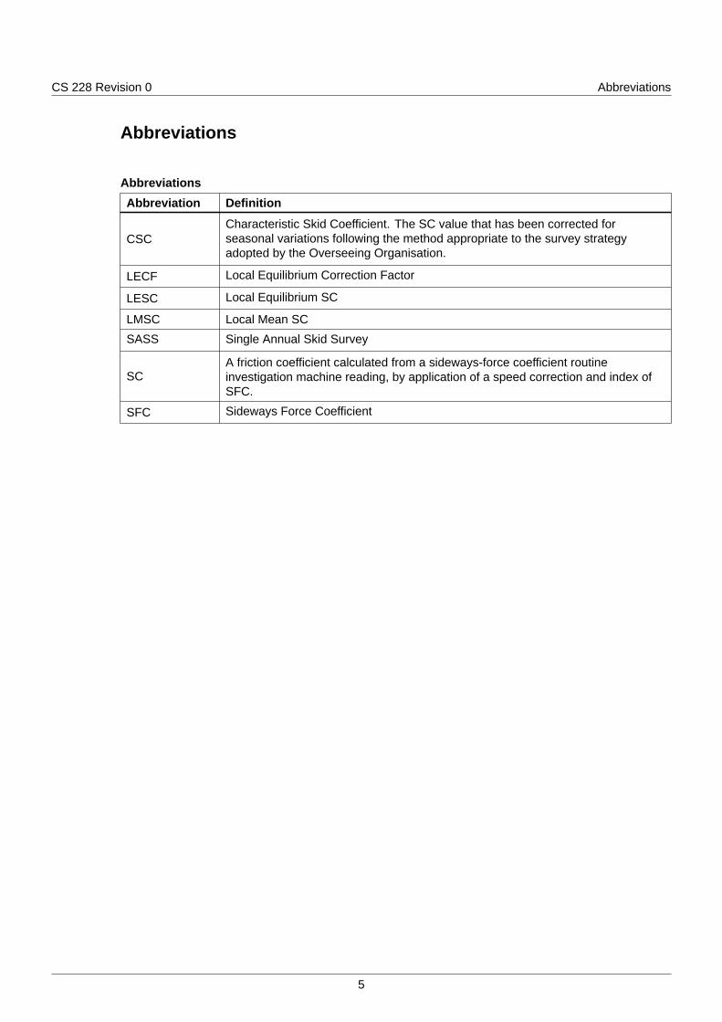
CS 228 Revision 0 Abbreviations
Abbreviations
AbbreviationsAbbreviation Definition
CSCCharacteristic Skid Coefficient. The SC value that has been corrected forseasonal variations following the method appropriate to the survey strategyadopted by the Overseeing Organisation.
LECF Local Equilibrium Correction Factor
LESC Local Equilibrium SC
LMSC Local Mean SC
SASS Single Annual Skid Survey
SCA friction coefficient calculated from a sideways-force coefficient routineinvestigation machine reading, by application of a speed correction and index ofSFC.
SFC Sideways Force Coefficient
5

CS 228 Revision 0 Terms and definitions
Terms and definitions
TermsTerm Definition
Index of SFCIndex of Sideways Force Coefficient. A factor applied to relate the values given bysideways-force coefficient routine investigation machines to historic values.
6

CS 228 Revision 0 S/1. Single annual skid survey (SASS) approach to ...
S/1. Single annual skid survey (SASS) approach to calculation of CSCS/1.1 The method shall use measurements from the preceding three years to characterise the long-term skid
resistance of the network.
S/1.2 The long-term value of skid resistance shall be used, with the mean network skid resistance in thecurrent year, to calculate a correction factor that is applied to the current year's data to make currentvalues consistent with the long-term average.
S/1.3 Sections which have had resurfacings carried out in the last three years shall be identified and removedfrom the calculation procedure for the correction factors.
NOTE The SASS approach takes account of yearly variation and therefore the calculations are affected bymaintenance carried out in the last three years.
S/1.4 Larger highway networks shall be split into smaller localities.
S/1.5 The correction factor shall be determined and applied separately within each locality.
NOTE The effect of seasonal variation varies in different geographical areas (such as due to different amountsof rainfall), therefore necessitating the need for a local approach.
S/1.6 The whole network shall be surveyed once during the test season in each year.
S/1.7 Surveys shall be planned such that in successive years each road length is tested in the early, middleand late parts of the season.
S/1.7.1 As a route tested in the early part of the season in year 1 could be tested in the late part of the seasonin year 2 and in the middle part of the season in year 3, in year four, it should be tested in the early partof the season again, and so forth.
S/1.8 Each site on the network shall be allocated to a locality according to the Overseeing Organisation.
NOTE A locality is a collection of road sections or routes for which a correction factor can be determined.
S/1.9 A locality shall be small enough so that similar weather conditions would normally be experienced withinit and large enough so that a stable value can be calculated to represent the long-term skid resistance.
NOTE This approach is based on the assumption that the climatic effects leading to seasonal variation caninfluence all the roads in a local area in a similar way.
S/1.10 All the road sections within each locality shall be surveyed within the same part of the test season.
NOTE By surveying all road sections within a locality at the same time, this method can remove a componentof the within-year seasonal variation as well as the variation between years.
S/1.11 The local equilibrium correction factor (LECF) is the correction factor that shall be used within eachlocality to bring the current year data to a level consistent with the long-term average.
NOTE The LECF is calculated in three stages.
S/1.12 The local equilibrium SC (LESC) shall be determined to represent the average skid resistance level forthe locality over recent years.
NOTE The LESC is the average SC, calculated for all valid 10-m sub-section measurements in the definedlocality over the three years that precede the current testing season.
S/1.13 The LESC shall contain surveys from each of the three parts of the test season with validmeasurements being those that were made in the required part of the test season, on the required testline, and on road surfaces that were at least 12 months old at the time of testing.
S/1.13.1 As a consequence of S/1.12, if a length of road has been resurfaced within the last four years then thatlength should be excluded from the LECF calculation.
S/1.14 The local mean SC (LMSC) shall be determined for the current survey.
NOTE The LMSC is the average of all valid 10-m sub-sections in the locality in the current year survey.
S/1.15 The LECF shall be determined by dividing the LESC by the LMSC, that is:
7

CS 228 Revision 0 S/1. Single annual skid survey (SASS) approach to ...
Equation S/1.15 Calculation of LECF
LECF =LESC
LMSC
S/1.16 The CSC for each 10-m sub-section shall be determined by multiplying the corrected SC by the LECF.
8

CS 228 Revision 0 S/2. Procedure for identifying sites requiring det...
S/2. Procedure for identifying sites requiring detailed investigationS/2.1 The Transport Scotland Interim Amendment - Skidding Resistance [Ref 2.N] shall be used to identify
sites requiring detailed investigation on the Scottish Trunk Road Network.
NOTE The document can be obtained from Transport Scotland.
9

CS 228 Revision 0 S/3. Determining locations requiring warning signs
S/3. Determining locations requiring warning signsS/3.1 The Transport Scotland Interim Amendment - Skidding Resistance [Ref 2.N] shall be used to determine
where warning signs are necessary on the Scottish trunk road network.
NOTE The document can be obtained from Transport Scotland.
10

CS 228 Revision 0 S/4. Normative references
S/4. Normative referencesThe following documents, in whole or in part, are normative references for this document and areindispensable for its application. For dated references, only the edition cited applies. For undatedreferences, the latest edition of the referenced document (including any amendments) applies.
Ref 1.N Highways England. GG 101, 'Introduction to the Design Manual for Roads andBridges'
Ref 2.N Transport Scotland. 'Transport Scotland Interim Amendment - Skidding Resistance'
11

© Crown copyright 2019.You may re-use this information (not including logos) free of charge in any format or medium, under the terms of the
Open Government Licence. To view this licence:visit www.nationalarchives.gov.uk/doc/open-government-licence/,
write to the Information Policy Team, The National Archives, Kew, London TW9 4DU,or email [email protected].

Design Manual for Roads and Bridges
PavementInspection & Assessment
CS 228Wales National Application Annex to CS 228Skidding resistance(formerly HD 28/15)
Revision 0
SummaryThis National Application Annex sets out the Welsh Government specific requirements onapplying seasonal correction to skid resistance measurements, the process for identifying sitesthat require a detailed investigation and for identifying sites where slippery road warning signsare required.
Feedback and EnquiriesUsers of this document are encouraged to raise any enquiries and/or provide feedback on the content and usageof this document to the dedicated Welsh Government team. The email address for all enquiries and feedback is:[email protected]
This is a controlled document.

CS 228 Revision 0 Contents
Contents
Release notes 2
Foreword 3Publishing information . . . . . . . . . . . . . . . . . . . . . . . . . . . . . . . . . . . . . . . . . . . . . . . . 3Contractual and legal considerations . . . . . . . . . . . . . . . . . . . . . . . . . . . . . . . . . . . . . . . . 3
Introduction 4Background . . . . . . . . . . . . . . . . . . . . . . . . . . . . . . . . . . . . . . . . . . . . . . . . . . . . . . 4Assumptions made in the preparation of this document . . . . . . . . . . . . . . . . . . . . . . . . . . . . . 4
Abbreviations 5
Terms and definitions 6
W/1. Single annual skid survey (SASS) approach to calculation of CSC 7Overview of SASS approach . . . . . . . . . . . . . . . . . . . . . . . . . . . . . . . . . . . . . . . . . . . . 7
W/2. Procedure for identifying sites requiring detailed investigation 9
W/3. Determining locations requiring warning signs 10
W/4. Normative references 11
1

CS 228 Revision 0 Release notes
Release notesVersion Date Details of amendments0 Aug 2019 Welsh Government National Application Annex to CS 228. A new publication
within the DMRB 2020 editorial revision programme.
2

CS 228 Revision 0 Foreword
Foreword
Publishing informationThis document is published by Highways England on behalf of the Welsh Government.
This documents supersedes HD 28/15, which is withdrawn.
Contractual and legal considerationsThis document forms part of the works specification. It does not purport to include all the necessaryprovisions of a contract. Users are responsible for applying all appropriate documents applicable totheir contract.
3

CS 228 Revision 0 Introduction
Introduction
BackgroundThis National Application Annex gives the Welsh Government-specific requirements related to theapplication of seasonal correction to skid resistance measurements, the process for identifying sitesthat require a detailed investigation and the identification of sites where slippery road warning signs arerequired.
Assumptions made in the preparation of this documentThe assumptions made in GG 101 [Ref 1.N] apply to this document.
4

CS 228 Revision 0 Abbreviations
Abbreviations
AbbreviationsAbbreviation DefinitionCSC Characteristic Skid Coefficient. The SC value that has been corrected for
seasonal variations following the method appropriate to the survey strategyadopted by the Overseeing Organisation.
LECF Local Equilibrium Correction Factor
LESC Local Equilibrium SC
LMSC Local Mean SC
SASS Single Annual Skid Survey
SCA friction coefficient calculated from a sideways-force coefficient routineinvestigation machine reading, by application of a speed correction and Index ofSFC.
5

CS 228 Revision 0 Terms and definitions
Terms and definitions
TermsTerm DefinitionIndex of SFC Index of Sideways Force Coefficient. A factor applied to relate the values given by
sideways-force coefficient routine investigation machines to historic values.
6

CS 228 Revision 0 W/1. Single annual skid survey (SASS) approach to ...
W/1. Single annual skid survey (SASS) approach to calculation of CSC
Overview of SASS approachW/1.1 The SASS approach shall use measurements from the preceding three years to characterise the
long-term skid resistance of the network, based upon a single annual survey of the network.
W/1.2 The long-term value of skid resistance shall be used, with the mean network skid resistance in thecurrent year, to calculate a correction factor which is applied to the current year's data to make currentvalues consistent with the long-term average.
W/1.3 Network sections that have had resurfacings carried out in the last three years shall be identified andremoved from the calculation procedure for the correction factors.
NOTE The SASS approach takes account of yearly variation and therefore the calculations are affected bymaintenance carried out in the last three years.
W/1.4 Larger networks shall be split into smaller localities.
NOTE The effect of seasonal variations will vary in different geographical areas (such as due to differentamounts of rainfall) necessitating a more local approach.
W/1.5 The correction factor shall be determined and applied separately within each locality.
W/1.6 The whole network shall be surveyed once during the test season in each year.
W/1.7 Surveys shall be planned such that in successive years each road length is tested in the early, middleand late parts of the season.
W/1.7.1 For example, a route may be tested in the early part of the season in year 1, tested in the late part ofthe season in year 2 and in the middle part of the season in year 3.
W/1.7.2 In year four the same route should be tested in the early part of the season again, and so forth.
NOTE Road sections are located within localities for North, Mid and South Wales.
W/1.8 A correction factor for each locality shall be calculated to represent long-term skid resistanceappropriate to the climatic region.
NOTE This approach is based on the assumption that the climatic effects leading to seasonal variation caninfluence all the roads in a local area in a similar way.
W/1.9 All the road sections within each locality shall be surveyed within the same part of the test season.
NOTE By surveying all road sections within a locality at the same time, this method can remove a componentof the within-year seasonal variation as well as the variation between years.
W/1.10 The local equilibrium correction factor (LECF) is the correction factor that shall be used within eachlocality to bring the current year data to a level consistent with the long-term average.
W/1.11 The LECF shall be calculated in three stages:
1) the local equilibrium SC (LESC) is determined to represent the average skid resistance level for thelocality over recent years;
2) the Local Mean SC (LMSC) is determined for the current survey as the average of all valid 10-msub-sections in the locality in the current year survey;
3) the LECF is determined by dividing the LESC by the LMSC, as:
Equation W/1.11 Calculation of LECF
LECF =LESC
LMSCW/1.11.1 If a length of road has been resurfaced within the last four years then that length should be excluded
from the LECF calculation.
7

CS 228 Revision 0 W/1. Single annual skid survey (SASS) approach to ...
NOTE 1 The LESC is the average SC, calculated for all valid 10m sub-section measurements in the definedlocality over the 3 years that precede the current testing season.
NOTE 2 The LESC contains surveys from each of the three parts of the test season with valid measurementsbeing those that were made in the required part of the test season, on the required test line, on roadsurfaces that were at least 12 months old at the time of testing.
W/1.12 The CSC for each 10-m sub-section shall be determined by multiplying the corrected SC by the LECF.
8

CS 228 Revision 0 W/2. Procedure for identifying sites requiring det...
W/2. Procedure for identifying sites requiring detailed investigationW/2.1 The Welsh Government method shall be used to identify sites requiring detailed investigation on
motorway and all-purpose trunk roads managed by Welsh Government.
NOTE The Welsh Government method can be obtained from Welsh Government.
W/2.2 Sites that have been identified for reasons other than skid resistance (see main document cl. 5.6) shallnot be removed by this process.
9

CS 228 Revision 0 W/3. Determining locations requiring warning signs
W/3. Determining locations requiring warning signsW/3.1 Sites which, as a result of a detailed investigation, have been identified as requiring treatment to
improve skid resistance shall have warning signs erected.
10

CS 228 Revision 0 W/4. Normative references
W/4. Normative referencesThe following documents, in whole or in part, are normative references for this document and areindispensable for its application. For dated references, only the edition cited applies. For undatedreferences, the latest edition of the referenced document (including any amendments) applies.
Ref 1.N Highways England. GG 101, 'Introduction to the Design Manual for Roads andBridges'
11

© Crown copyright 2019.You may re-use this information (not including logos) free of charge in any format or medium, under the terms of the
Open Government Licence. To view this licence:visit www.nationalarchives.gov.uk/doc/open-government-licence/,
write to the Information Policy Team, The National Archives, Kew, London TW9 4DU,or email [email protected].