cs14 406 80386-mod1
TRANSCRIPT

A K H I L A P D A S
A S S I S TA N T P R O F E S S O R
D E PA RT M E N T O F E C E
A RYA N E T I N S T I T U T E O F T E C H N O L O G Y
PA L A K K A D
MICROPROCESSOR BASED DESIGN
MODULE I
80386, 80486 & PENTIUM PROCESSOR

OV ERV IEW
ECE , ARYANET INSTITUTE OF TECHNOLOGY
2
80386 MICROPROCESSOR

80386: OVERVIEW
First 32-bit microprocessor in the x86 family released in 1986
32-bit ALU, 32-bit Registers, 32-bit Data Bus, 32-bit Address
Bus
Maximum physical memory 4 Gb
Packaging: 132 pin PGA(Pin Grid Array)
Three Modes of Operation:
Real mode
Protected virtual address mode(PVAM)
Virtual 8086 mode(V86 mode)
ECE , ARYANET INSTITUTE OF TECHNOLOGY
3

PIN S A N D S IGN A LS
ECE , ARYANET INSTITUTE OF TECHNOLOGY
4
HARDWARE FEATURES
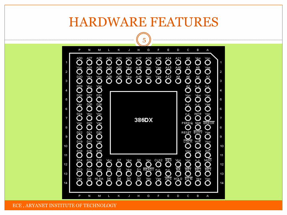
HARDWARE FEATURES
ECE , ARYANET INSTITUTE OF TECHNOLOGY
5
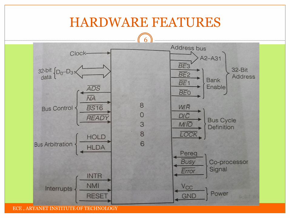
HARDWARE FEATURES
ECE , ARYANET INSTITUTE OF TECHNOLOGY
6
SIGNAL DESCRIPTION
D0-D31: 32 pins for data transfer. It can access byte, word or double
word from memory or I/O device
W/𝑹 : The write/read output distinguishes the write and read cycles
from one another.
D/𝑪 : This data/control output pin distinguishes between a data transfer
cycle from a machine control cycle like interrupt acknowledge.
M/𝐈𝐎: This output pin differentiates between the memory and I/O
cycles.
𝐋𝐎𝐂𝐊: This output pin enables the CPU to prevent the other bus
masters from gaining the control of the system bus. Asserted low by
LOCK prefix instructions.
ECE , ARYANET INSTITUTE OF TECHNOLOGY
7

SIGNAL DESCRIPTION
RESET: A high at this input pin suspends the current operation and
restart the execution from the starting location.
𝐀𝐃𝐒: The address status output pin indicates that the address is output
by the processor. The 80386 does not have any ALE signals and so this
signals may be used for latching the address to external latches.
𝐑𝐄𝐀𝐃𝐘: The ready signals indicates to the CPU that the previous bus
cycle has been terminated and the bus is ready for the next cycle.
𝑩𝑺𝟏𝟔: The bus size 16 input pin allows the interfacing of 16 bit
devices with the 32 bit wide 80386 data bus. If 0, 16-bit data bus is
selected.
ECE , ARYANET INSTITUTE OF TECHNOLOGY
8

SIGNAL DESCRIPTION
HOLD: The bus hold input pin enables the other bus masters to gain
control of the system bus if it is asserted.
HLDA: The bus hold acknowledge output indicates that a valid bus
hold request has been received and the bus has been relinquished by
the CPU.
𝐁𝐔𝐒𝐘: The busy input signal indicates to the CPU that the coprocessor
is busy with the allocated task.
PEREQ: Request from co-processor to relinquish control of bus so that
co-processor gets a direct connection
𝐍𝐀: The next address input pin, if activated(logic 0),processor outputs
the address of next instruction/data. It allows address pipelining, during
80386 bus cycles
ECE , ARYANET INSTITUTE OF TECHNOLOGY
9

SIGNAL DESCRIPTION
𝐄𝐑𝐑𝐎𝐑: The error input pin indicates to the CPU that the
coprocessor has encountered an error while executing its
instruction.
INTR: This interrupt pin is a maskable interrupt request, that can
be masked using the IF of the flag register.
NMI: Non maskable interrupt request
VCC: These are system power supply lines.
VSS: These are return lines for the power supply.
N/C : No connection pins are expected to be left open while
connecting the 80386 in the circuit.
ECE , ARYANET INSTITUTE OF TECHNOLOGY
10

M OD ES OF OPER ATION
S EGM EN TATION
PA GIN G
ECE , ARYANET INSTITUTE OF TECHNOLOGY
11
MEMORY MANAGEMENT
MEMORY MANAGEMENT-OVERVIEW
ECE , ARYANET INSTITUTE OF TECHNOLOGY
12
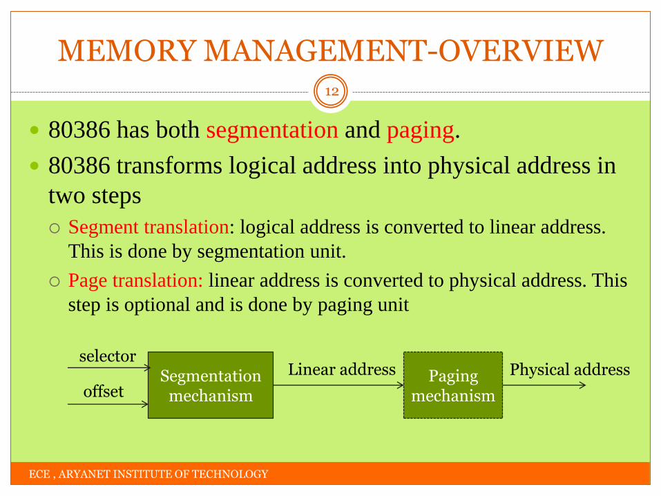
80386 has both segmentation and paging.
80386 transforms logical address into physical address in
two steps
Segment translation: logical address is converted to linear address.
This is done by segmentation unit.
Page translation: linear address is converted to physical address. This
step is optional and is done by paging unit
Segmentation mechanism
Paging mechanism
selector
offset
Linear address Physical address

MODES OF OPERATION
ECE , ARYANET INSTITUTE OF TECHNOLOGY
13
Real address mode
Protected virtual address mode
Virtual 8086 mode

REAL ADDRESS MODE
ECE , ARYANET INSTITUTE OF TECHNOLOGY
14
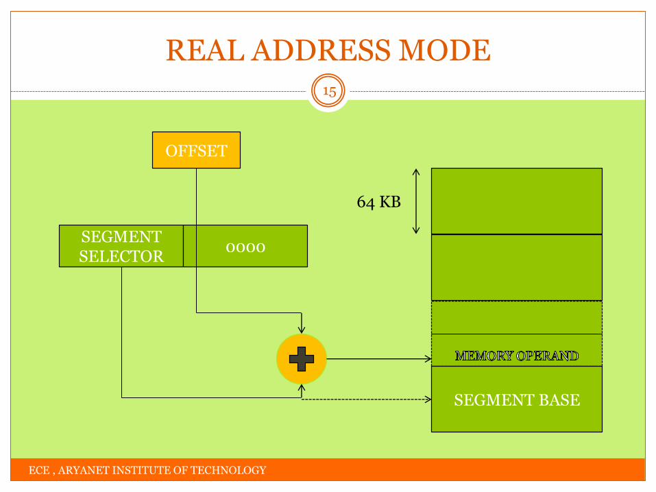
80386 enters real address mode when it is reset.
Works as fast 8086 with 32-bit registers.
Uses 20-bit address to access 1MB of physical memory
space
Segment register is left shifted 4 times and offset is added.
The size of segments are 64KB and can be overlapped.
Hence 32 bit offset value should be less than 0000FFFFh
Paging unit is disabled.
REAL ADDRESS MODE
ECE , ARYANET INSTITUTE OF TECHNOLOGY
15
OFFSET
SEGMENT SELECTOR
0000
SEGMENT BASE
64 KB
PROTECTED VIRTUAL ADDRESS MODE
ECE , ARYANET INSTITUTE OF TECHNOLOGY
16
Protection Enable (PE) bit in control register CR0 is set to enter into PVAM.
Large address space
4GB of physical memory space
64TB of virtual memory space
Contents of segment registers are used as selectors to address descriptors
Descriptors contain segment limit, base address and access rights bits of the
segment
Offset is added with segment base address to calculate linear address
This linear address is used as physical address if paging is disabled
Else paging unit converts it into physical address

PROTECTED VIRTUAL ADDRESS MODE
ECE , ARYANET INSTITUTE OF TECHNOLOGY
17
c
c
c
c
SELECTOR OFFSET
MEMORY OPERAND
SEGMENT BASE ADDRESS
SEGMENT LIMIT
UP TO
4 GB
SELECTED
SEGMENT
Protected Mode Addressing Without Paging Unit
48 / 32 – BIT POINTER
c
c
0 31 / 15 47 / 31
SELECTOR OFFSET
ACCESS RIGHT
LIMIT
BASE ADDRESS
SEGMENT DESCRIPTOR
+

PROTECTED VIRTUAL ADDRESS MODE
ECE , ARYANET INSTITUTE OF TECHNOLOGY
18

VIRTUAL 8086 MODE
ECE , ARYANET INSTITUTE OF TECHNOLOGY
19
In its protected mode of operation, 80386DX provides a virtual
8086 operating environment to execute the 8086 programs.
Processor can switch from PVAM to V86 by setting VM bit in the
EFLAG register to logic 1.
The real mode can also be used to execute the 8086 programs
along with the capabilities of 80386, like protection and a few
additional instructions.
Once the 80386 enters the protected mode from the real mode, it
cannot return back to the real mode without a reset operation.
Thus, the virtual 8086 mode of operation of 80386, offers an
advantage of executing 8086 programs while in protected mode.
VIRTUAL 8086 MODE
ECE , ARYANET INSTITUTE OF TECHNOLOGY
20
The address forming mechanism in virtual 8086 mode is
exactly identical with that of 8086 real mode.
In virtual mode, 8086 can address 1Mbytes of physical
memory that may be anywhere in the 4Gbytes address space
of the protected mode of 80386.
In virtual mode, the paging mechanism and protection
capabilities are available at the service of the programmers.
The 80386 supports multiprogramming, hence more than
one programmer may be use the CPU at a time.
VIRTUAL 8086 MODE
ECE , ARYANET INSTITUTE OF TECHNOLOGY
21
Paging unit may not be necessarily enabled in virtual
mode, but may be needed to run the 8086 programs
which require more than 1Mbyte of memory for
memory management function.
In virtual mode, the paging unit allows only 256 pages,
each of 4Kbytes size.
Each of the pages may be located anywhere in the
maximum 4Gbytes physical memory.
SEGMENTATION
ECE , ARYANET INSTITUTE OF TECHNOLOGY
22
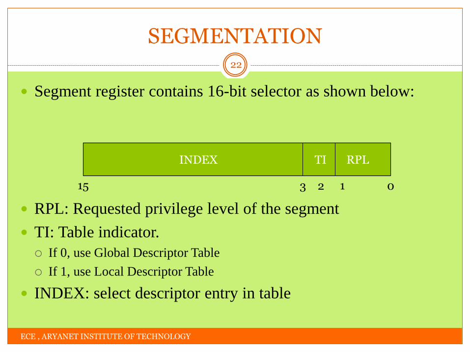
Segment register contains 16-bit selector as shown below:
RPL: Requested privilege level of the segment
TI: Table indicator.
If 0, use Global Descriptor Table
If 1, use Local Descriptor Table
INDEX: select descriptor entry in table
INDEX TI RPL
0 1 2 3 15
SEGMENTATION
ECE , ARYANET INSTITUTE OF TECHNOLOGY
23
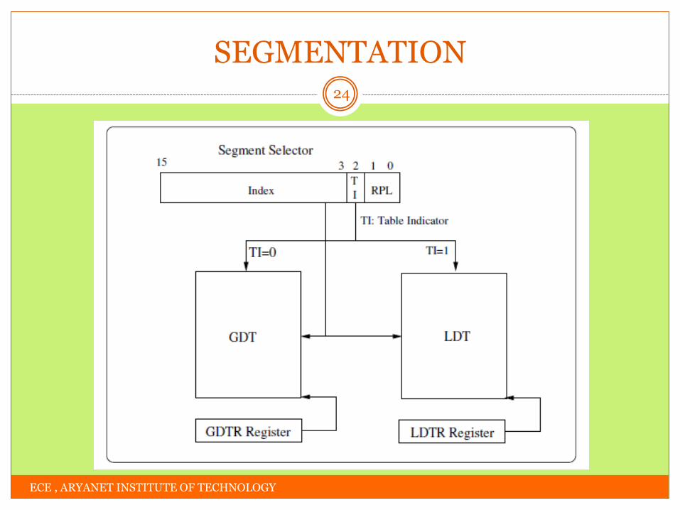
A descriptor table is an array of 8K descriptors
Each descriptor is 8 byte
Hence size of descriptor table is 8K X 8= 64KB
GDT contains global descriptors common to all the tasks. There
will be only 1 GDT in a system
LDT contains descriptors specific to a particular task. There will be
as many LDTs as there are application tasks
Base address of descriptor table will be in corresponding descriptor
table register (GDTR or LDTR)
Using segment selector & descriptor table register, corresponding
descriptor is chosen
SEGMENTATION
ECE , ARYANET INSTITUTE OF TECHNOLOGY
24

SEGMENTATION
ECE , ARYANET INSTITUTE OF TECHNOLOGY
25
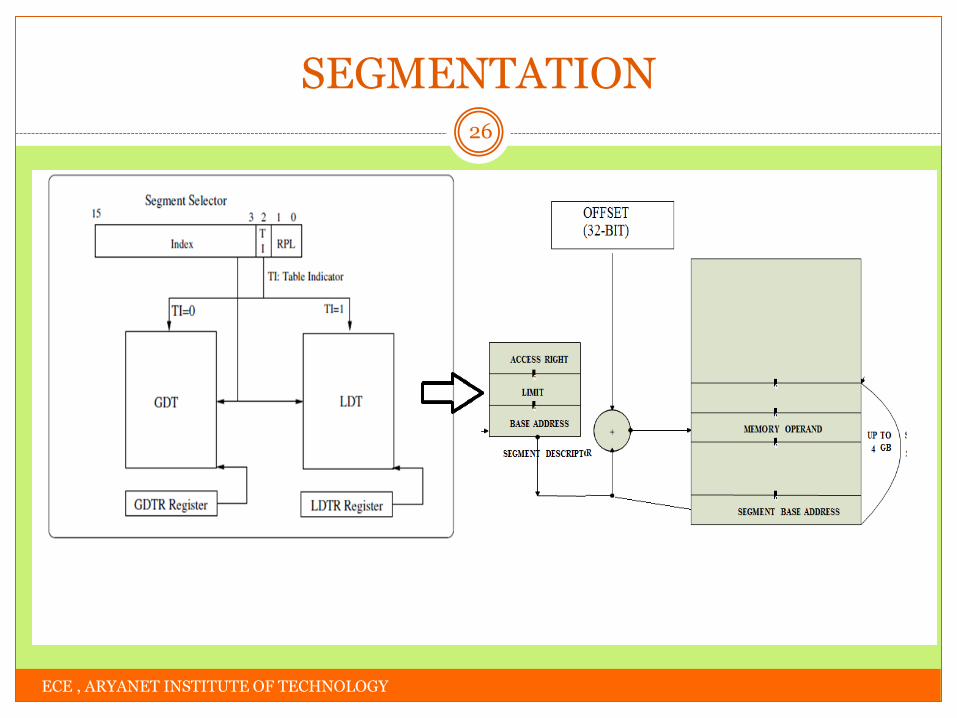
Descriptor(8 byte) contains segment limit, access rights
and base address(32-bit) of a particular segment
The base address is used to locate the data segment
Offset mentioned in the instruction is added with this base
address to get the physical address of the operand.
SEGMENTATION
ECE , ARYANET INSTITUTE OF TECHNOLOGY
26

PAGING
ECE , ARYANET INSTITUTE OF TECHNOLOGY
27
In paging concept, each segment is composed of
numerous pages each of 4KB.
The base address of each page is stored in a page table.
There will be many such page tables.
The base address of page table and other details (page
descriptor) will be in a page directory.
The base address of current page directory will be in CR3
register
PAGING
ECE , ARYANET INSTITUTE OF TECHNOLOGY
28
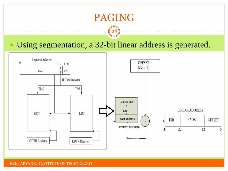
Using segmentation, a 32-bit linear address is generated.

PAGING
ECE , ARYANET INSTITUTE OF TECHNOLOGY
29
Using this linear address, an operand from a page is
selected as shown below:
PAGING
ECE , ARYANET INSTITUTE OF TECHNOLOGY
30
CR3 register contains the base address of current page
directory. Using DIR in linear address, a corresponding
page descriptor is selected.
Page descriptor contains base address of page table. The
PAGE field of linear address is used to select the
corresponding page table entry.
The page table entry contains the base address of the page
we are looking for. The OFFSET field in the linear
address is used to locate the operand in physical memory.

FEATU R ES
ECE , ARYANET INSTITUTE OF TECHNOLOGY
31
80486 MICROPROCESSOR

80486: FEATURES
ECE , ARYANET INSTITUTE OF TECHNOLOGY
32
32-bit processor introduced by INTEL in 1989
168 pin PGA package
1st processor with inbuilt Floating Point Unit(FPU) i.e, co-processor 80487 is inbuilt within 80486 chip.
8 KB on-chip cache was added. On-chip cache is L1 cache
Off-chip cache is L2 cache
Clock doubling was provided. Internal clock frequency is twice that of external clock
5-stage pipelining PF(Pre-Fetch), D1(Decode 1), D2(Decode 2), EX(EXecute) and WB(Write
Back)

80486: FEATURES
ECE , ARYANET INSTITUTE OF TECHNOLOGY
33
Support burst mode transfer.
Transferring multiple bytes of data across bus in 1 long memory
cycle
Boundary Scan Test and on-line parity check were
introduced to make it more susceptible to fault-tolerant
architectures.
New instructions were introduced such as:
BSWAP: Byte Swap
XADD: eXchange and ADD

FEATU R ES
ECE , ARYANET INSTITUTE OF TECHNOLOGY
34
PENTIUM

PENTIUM: FEATURES
ECE , ARYANET INSTITUTE OF TECHNOLOGY
35
32-bit processor released by INTEL in 1993
32 bit address bus and 64 bit data bus
Data width is doubled, hence double the amount of data can be
sent/received from/to memory
Superscalar architecture
5-stage pipelining
Two integer execution units-U & Vpipes
U pipe handles more complex operations
Faster FPU
8-stage pipelining
Upto 10X speed for common operations like ADD, MULTIPLY and LOAD

PENTIUM: FEATURES
ECE , ARYANET INSTITUTE OF TECHNOLOGY
36
Branch prediction unit
Used to prevent pipeline stalling
Technique called speculative execution is implemented
One branch is taken and executed while branch condition is
evaluated
If speculative execution had taken the correct branch, all is good.
Otherwise pipeline is flushed
2 types of branch prediction- static & dynamic
In static prediction, loop condition is repeated, since loop’s exit
condition is false in most cases.
Dynamic prediction relies on past history of branching.

PENTIUM: FEATURES
ECE , ARYANET INSTITUTE OF TECHNOLOGY
37
Separate data & instruction cache
Each cache is 8KB in size with 32-byte line size
Allows 2MB & 4MB page sizes
System management mode
Power dissipation is reduced by switching off all peripherals and
even the system when it is not in use.

EN D OF M OD U LE 1
ECE , ARYANET INSTITUTE OF TECHNOLOGY
38
THANK YOU