crypton cml3000 - crypton technology · pdf filecrypton cml3000 mid rise lift 3000kg operating...
TRANSCRIPT

Crypton CML3000
Mid Rise Lift
3000Kg
OPERATING INSTRUCTIONS
I322991 Iss 2 March 2015

Operating Instructions CML3000
I322991 Iss 2 Page 2
Table of Contents
1 FOREWORD ......................................................................................................................... 4
1.1 OBLIGATIONS OF THE USER: ................................................................................................... 4
1.2 OBLIGATIONS OF THE OPERATOR: .......................................................................................... 4
1.3 DANGERS WHEN OPERATING THE LIFT: ................................................................................... 4
1.4 ORGANISATIONAL REQUIREMENTS: ........................................................................................ 5
1.5 MAINTENANCE WORK AND REPAIRING FAULTS: ...................................................................... 5
1.6 GUARANTEE AND LIABILITY ................................................................................................... 5
2 RECORD OF INSTALLATION ............................................................................................... 6
3 RECORD OF HANDING OVER ............................................................................................. 7
4 GENERAL INFORMATION ................................................................................................... 8
4.1 INSTALLATION AND CHECK OF THE AUTOMOTIVE LIFT .............................................................. 8
4.2 WARNING SYMBOLS ............................................................................................................. 8
5 MASTER DOCUMENT OF THE AUTOMOTIVE LIFT ........................................................... 9
5.1 LIFT–MANUFACTURER ........................................................................................................... 9
5.2 APPLICATION ....................................................................................................................... 9
5.3 CHANGES TO THE CONSTRUCTION .......................................................................................... 9
5.4 DISPLACEMENT OF THE AUTOMOTIVE LIFT .............................................................................. 9
6 CE DECLARATION OF CONFORMITY ............................................................................ 10
6.1 DRIVE ON DIRECTIONS ........................................................................................................ 11
7 TECHNICAL INFORMATION ............................................................................................. 14
7.1 TECHNICAL RATINGS ........................................................................................................... 14
7.2 SAFETY DEVICE .................................................................................................................... 14
7.3 DATA SHEET ....................................................................................................................... 15
7.4 HYDRAULIC DIAGRAM DRAWING ......................................................................................... 16
7.5 ELECTRIC DIAGRAM ............................................................................................................. 17
8 SAFETY REGULATIONS ..................................................................................................... 18
9 OPERATING INSTRUCTIONS ............................................................................................ 19
9.1 LIFTING THE VEHICLE ........................................................................................................... 19
9.2 LOWERING THE VEHICLE ...................................................................................................... 20
9.3 CHANGE THE OPERATING POSITION...................................................................................... 20

Operating Instructions CML3000
I322991 Iss 2 Page 3
10 TROUBLESHOOTING ....................................................................................................... 20
10.1 LOWERING ON AN OBSTACLE ............................................................................................. 21
10.2 EMERGENCY LOWERING ..................................................................................................... 21
11 INSPECTION AND MAINTENANCE ............................................................................... 21
11.1 MAINTENANCE PLAN OF THE LIFT ....................................................................................... 22
11.1.1 TURNING MOMENT FOR SCREWS .............................................................................................. 23
11.2 HOW OFTEN MUST THE LIFT BE CLEANED? ........................................................................... 23
12 SAFETY CHECK ................................................................................................................ 24
13 INSTALLATION ................................................................................................................ 24
13.1 REGULATIONS ................................................................................................................... 24
13.2 CHANGE THE INSTALLATION PLACE .................................................................................... 25
14 CHOICE OF DOWEL LENGTH ....................................................................................... 26
14.1 WITHOUT FLOOR PAVEMENT OR TILE SURFACE ................................................................. 26 14.2 WITH FLOOR PAVEMENT OR TILE SURFACE ....................................................................... 27
15 FIRST SAFETY CHECK BEFORE INSTALLATION ...................................................... 28
15.1 REGULAR SAFETY CHECK AND MAINTENANCE ................................................................. 29 15.2 REGULAR SAFETY CHECK AND MAINTENANCE ................................................................. 30 15.3 REGULAR SAFETY CHECK AND MAINTENANCE ................................................................. 31 15.4 REGULAR SAFETY CHECK AND MAINTENANCE ................................................................. 32 15.5 REGULAR SAFETY CHECK AND MAINTENANCE ................................................................. 33 15.6 REGULAR SAFETY CHECK AND MAINTENANCE ................................................................. 34 15.7 REGULAR SAFETY CHECK AND MAINTENANCE ................................................................. 35 15.8 REGULAR SAFETY CHECK AND MAINTENANCE ................................................................. 36 15.9 REGULAR SAFETY CHECK AND MAINTENANCE ................................................................. 37 15.10 EXTRAORDINARY SAFETY CHECK AND MAINTENANCE .................................................... 38
16 AFTER SALES SERVICE ................................................................................................ 39
16.1 ON-SITE SERVICE / OVERHAUL / SPARE PARTS ............................................................... 39 16.2 CONTACT DETAILS ..................................................................................................... 39

Operating Instructions CML3000
I322991 Iss 2 Page 4
1 Foreword
Crypton Lifts are the result of over 100 years experience in the automotive industry.
The high quality and the superior concept ensure reliability, a long lifetime and above all, economic
business solution. To avoid unnecessary damage, injury or even death, read the operating instructions
with care and observe the content.
Crypton is not responsible for incidents involving the use for applications other than those for
which they were designed.
Continental Corporation is not liable for any resulting damages. The user carries the risk alone.
1.1 Obligations of the user:
- To observe and adhere to the operating instructions.
- To follow the recommended inspection and maintenance procedures and carry out the prescribed
tests.
- The operating instructions must be observed by all persons working with or around the lift.
- Above all, the chapter entitled “Safety Regulations“ is very important and must be closely adhered
to.
- In addition to the safety regulations stated in the operating instructions manual, the appropriate
safety regulations and the operating procedures of the place of operation must also be considered.
1.2 Obligations of the operator:
The operator is obliged to allow only those persons complying with the following requirements to
work with or around the unit.
- Persons who are familiar with the basic regulations concerning labor safety and accident
prevention and who have been trained to operate the particular unit.
- Persons who have read and understood the chapters concerning safety and warning symbols.
Such persons are required to confirm that they have read and understood the chapter on safety
and warning symbols by signing the appropriate form.
1.3 Dangers when operating the lift:
Crypton lifts are designed and built according to technical standards and the approved regulations
for technical safety. The use of Crypton lifts for purposes other than those for which they were
designed may result in injury or even death.
The lift must only be operated:
- For its intended purpose.
- In faultless condition concerning technical safety.

Operating Instructions CML3000
I322991 Iss 2 Page 5
1.4 Organisational requirements:
- The instructions for use are to be kept at the place of operation, easily accessible at all times.
- In addition to the instructions for use, rules pertaining to other regulations i.e. accident prevention
and environmental rules are to be observed and adhered to.
- The owner of the Crypton lifting system must ensure that operators and persons working with
or around the lift occasionally conduct “refresher” courses to ensure that the appropriate operating
procedures and safety precautions are known.
- Personal Protective Equipment (PPE) must be used according to the appropriate regulations.
- All safety and danger signs on or around the lift are to be observed and followed!
- Spare parts must comply with the technical requirements specified by the manufacturer.
This is only warranted with original parts.
- Observe and adhere to the specified time intervals between tests and inspections.
1.5 Maintenance work and repairing faults:
- Adjustments, maintenance and inspections are to be followed according to the time intervals
specified. Details regarding the exchange of parts and components as mentioned in the operating
instructions are to be adhered to.
Such work may only be carried out by expert personnel.
- After maintenance and repair work, loose screws, nuts and bolts must always be firmly
tightened!
1.6 Guarantee and liability
- Our “General conditions of selling and delivering” are enforced.
There will be no guarantee or liability for incidents involving injuries, death or damage to
equipment if these incidents are the result of one or more of the following reasons:
- Inappropriate use of the lift
- Inappropriate installation, initiation, operation and maintenance of the lift.
- Use of the lift while one or several safety devices do not work, do not work properly or are not
installed properly.
- Failure to follow the regulations of the operating instructions regarding transport, storage,
installation, initiation, operation and maintenance of the lift.
- Unauthorized changes to the structure of the lift without first asking the manufacturer.
- Unauthorized changes or adjustments of important components of the lift (e.g. driving elements,
power rating, motor speed, etc.).
- Incorrect maintenance practices.
- Catastrophes, acts of God or external reasons.

Operating Instructions CML3000
I322991 Iss 2 Page 6
Fill out, sign and photocopy this sheet and send the original to the lift manufacturer.
The copy remains in the manual.
Continental Automotive Trading UK Ltd
36 Gravelly Industrial Park
Birmingham B24 8TA
United Kingdom
2 Record of installation
The automotive lift
with the serial number:...................................... was installed on:...............................................
at the firm:................................................. …… in:......................................................……….....
The initial safety check was carried out and the lift was started.
The installation was carried out by the operating authority/competent person (please delete as
applicable).
The initial safety check was carried out by a competent person before the initial operation.
The operating authority attests to the correct installation of the automotive lift, the competent person
attests to the correct initial operation.
Used dowels (*): ________________________________ (Type/Name)
Minimum anchorage depth (*) kept: _________________mm � ok
Starting torque (*) kept: __________________________NM � ok
...................... ................................................. ............. ..........................................
Date Name of the operating authority Signature of the operating authority
...................... ................................................. ............ ..........................................
Date Name of the competent person Signature of the competent person
Your customer service: ................................................................................. (stamp)
(*) see supplement of the dowel manufacturers

Operating Instructions CML3000
I322991 Iss 2 Page 7
3 Record of handing over
The automotive lift
with the serial number: ............................................ was installed on:...............................
at the firm:................................................. ……... in:.........................................................
The safety was checked and the lift was started.
The persons listed below were introduced after the installation of the automotive lift. The introduction
was carried out by an erector of the lift manufacturer or from a franchised dealer (competent person).
............................................ ..................................................... ............................................
Date Name Signature
............................................ ..................................................... ............................................
Date Name Signature
............................................ ..................................................... ............................................
Date Name Signature
............................................ ..................................................... ............................................
Date Name Signature
............................................ ..................................................... ............................................
Date Name Signature
............................................ ..................................................... ............................................
Date Name Signature
.................................. ......................................................... ......................................................
Date Name of the competent person Signature of the competent person
Your customer service: ............................................................................................... (stamp)

Operating Instructions CML3000
I322991 Iss 2 Page 8
4 General information
The document “Operating Instructions and Documentation” contains important information
about installation, operation and maintenance of the automotive lift.
- Confirmation of installation of the automotive lift is recorded on the “Record of installation”
form and must be signed and returned to the manufacturer.
- Confirmation of initial, regular and extraordinary service/safety checks is recorded in the respective
review forms. The forms are used to document the checks. They should not be removed from the
manual.
All changes to the structure and any change of location of the automotive lift must be registered
in the “Master document” of the lift.
4.1 Installation and check of the automotive lift
Only specialized staff/specialists are allowed to perform repair and maintenance work, and only
such specialists are allowed to conduct safety checks on the lift. For the purpose of this document,
these specialists will be called “experts” and “competent persons”.
Experts are persons (for example, self-employed engineers) who have received instructions and have
the appropriate experience to check and test automotive lifts. They are aware of the work involved and
know the accident prevention regulations.
Competent persons are persons who have acquired adequate knowledge and experience with
automotive lifts. They have completed the appropriate training provided by the lift manufacturer
(for example, the servicing technicians of the manufacturer or dealer are regarded as competent).
4.2 Warning symbols
The three symbols below are used to indicate danger and other important information. Pay attention
to areas on and around the lift that are marked with these symbols.
Danger! This sign indicates danger. Ignoring this warning may result in injury or
even death.
Caution! This sign cautions against possible damage to the automotive lift or
other material objects in the case of improper use.
Attention! This sign indicates an important function or other important
information regarding the operation of the lift.

Operating Instructions CML3000
I322991 Iss 2 Page 9
5 Master document of the automotive lift
5.1 Lift–manufacturer
Continental Automotive Trading UK Ltd
36 Gravelly Industrial Park
Birmingham B24 8TA
United Kingdom
5.2 Application
The automotive lift CML3000 is a lifting mechanism for lifting motor vehicles with a laden weight of up
to 3000 kg. The max. Load distribution is 3:2 in or against drive-on direction.
The automotive lift is only designed for servicing vehicles.
It’s not allowed to install the standard-automotive lift in a hazardous location or washing bays.
The lift is only designed for servicing vehicles. It is not allowed to carry persons on the lift.
The lift is moveable. You can re-position it on any solid and level surface.
The lift can also be bolted to the floor with dowels.
Important: You must distinguish between the vehicle with rear drive and front drive. (See next
pages)
5.3 Changes to the construction
Changes to the construction, expert review, resumption of work (date, type of change, signature
of the expert)
..............................................................................................................................................................
..............................................................................................................................................................
..............................................................................................................................................................
Name and address of the expert
................................ ......................................................................................
Place and date Signature of the expert
5.4 Displacement of the automotive lift
Displacement of the automotive lift, review by competent person, resumption of work (date,
type of change, signature of the competent person)
..............................................................................................................................................................
..............................................................................................................................................................
..............................................................................................................................................................
Name and address of the competent person
........................................................... ............................................................
Place and date Signature of the competent person

Operating Instructions CML3000
I322991 Iss 2 Page 10
6 CE Declaration of Conformity

Operating Instructions CML3000
I322991 Iss 2 Page 11
6.1 Drive on directions
Front drive vehicle
Operating Instructions CML3000
I322991 Iss 2 Page 12
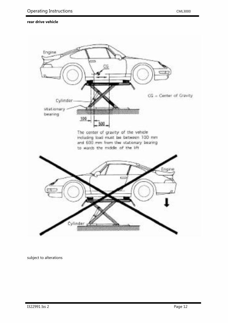
rear drive vehicle
subject to alterations

Operating Instructions CML3000
I322991 Iss 2 Page 13
The motor of the vehicle must be always located above the stationary bearing, otherwise
the vehicle can fall down.
The centre of gravity of the vehicle including load must be between 100 mm and 600 mm
from the stationary bearing towards the middle of the lift.

Operating Instructions CML3000
I322991 Iss 2 Page 14
7 Technical Information
7.1 Technical ratings
Capacity: 3000 kg
Load distribution: 3:2 in or against drive-on direction
(Observe the centre of gravity of the lift)
max height: max. 980 mm
Lifting time: approx. 11 sec without load
Lowering time: approx. 35 sec without load
Hydraulic pressure approx. 230 bar
Pressure relief valve approx. 260 bar
Hydraulic Oil (not supplied) high quality 32 cst oil (e.g. HLP 32 LTD. OEST
Company)
Note: use ATF-Suffix hydraulic-oil (OEST
Company) if the ambient temperature is under
5 degrees centigrade
Oil tank approx. 8 Litre
Sound level ≤ 75 dB(A)
Connection by customer 230V a.c. nominal, single phase 50/60 Hz
with 16 Amp (time lag fuse)
Observe the respective country regulations
7.2 Safety device
1. Flow control valve
Safety device against over-rapid raising or lowering
2. Pressure relief valve
Overprint-safety of the hydraulic system
3. Foot protector
Safety device against squeeze
4. Lockable main switch
Safety device against unauthorised operation
5. “Totmann” control
Let go off the operation button and the lift stops the movement

Operating Instructions CML3000
I322991 Iss 2 Page 15
7.3 Data sheet
Operating Instructions CML3000
I322991 Iss 2 Page 16
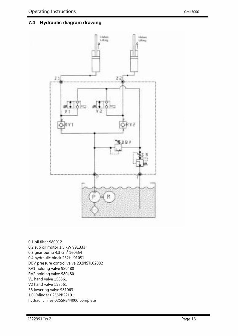
7.4 Hydraulic diagram drawing
0.1 oil filter 980012
0.2 sub oil motor 1,5 kW 991333
0.3 gear pump 4,3 cm³ 160554
0.4 hydraulic block 232HL01051
DBV pressure control valve 232NSTL02082
RV1 holding valve 980480
RV2 holding valve 980480
V1 hand valve 158561
V2 hand valve 158561
SB lowering valve 981063
1.0 Cylinder 025SPB22101
hydraulic lines 025SPB44000 complete

Operating Instructions CML3000
I322991 Iss 2 Page 17
7.5 Electric diagram
Operating Instructions CML3000
I322991 Iss 2 Page 18
8 Safety regulations
If you use the automotive lift, the following European regulations must be considered:
BGG945: Examine of automotive-lifts; BGR500 Using automotive-lifts; (VBG14).
The following regulations are very important:
Observe the detailed operating instructions.
The laden weight of the lifted vehicle must not exceed 3000 kg
The maximum load distribution is 3:2 in or against the drive-on direction.
Observe the centre of gravity.
The lift must be in its lowest position, before the vehicle can be driven over it.
The lift must only be used on a solid and level surface.
While working with the lift the operating instructions must be followed.
Only trained personnel over the age of 18 years old are to operate this lift.
No one is to stand within the working area (danger area) during lifting and lowering.
No one is to be raised or lowed either directly or on the vehicle by the automotive lift.
No one is to climb onto the automotive lift or onto an already raised vehicle.
The lift must be checked by an expert after any changes have been made to the construction
The main switch must be switched off and locked before work on the vehicle can commence.
This is a safety precaution to ensure that the lift does not move during work.
The main switch must be switched off and locked before any maintenance or repair work on
the automotive lift itself can be carried out.
During lifting or lowering the operator must observe the vehicle to ensure that the vehicle and
the lift are functioning correctly.
Installation of the standard vehicle lift in hazardous or dangerous locations such as washing
bays is dangerous and is not allowed.
Always check the centre of gravity of the vehicle if heavy parts (eg the engine) are removed.
If heavy parts must be removed, then the centre of gravity will change.
Secure the vehicle before removing parts to avoid the possibility of the vehicle becoming
insecure.
Vehicles with low ground clearance, optional equipment (sport equipment), or sport vehicles,
should be previously measured to ensure damage does not occur.

Operating Instructions CML3000
I322991 Iss 2 Page 19
9 Operating instructions
All Safety Regulations must be observed during working with the automotive lift.
Read the safety regulations section carefully before working with the lift!
If the vehicle is very short, the ramps must be taken off to guarantee that all wheels are
free.
If the vehicle is very long, the carrying arms must be pulled out to extend the platforms.
9.1 Lifting the vehicle
Remove the ramps, if the wheelbase is too short and the wheels are standing on the ramps.
Observe the centre of gravity.
If necessary fold out the extension ramps.
Chock the vehicle against rolling and put into gear.
Check around the lift to make sure that there are no objects or people in the immediate area
of the lift or on the lift itself.
Switch on the control system; main switch on position ”1” (see pic.1)
Position polymer supports under the pick-up points which are described by the vehicle
manufacturer. Do not lay them on their side, as the vehicle could tip over!
Raise the lift by pressing the button “Lifting“.
Stop lifting when the wheels are free to check the safe position of the vehicle on the polymer
pads.
Lift the vehicle to the working height by press the button “Lifting“ .
Observe the complete process.
Pic.1:
operating unit
Button “Lifting”
Button “Lowering”
Main switch
Operating Instructions CML3000
I322991 Iss 2 Page 20
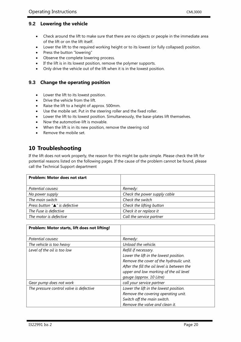
9.2 Lowering the vehicle
Check around the lift to make sure that there are no objects or people in the immediate area
of the lift or on the lift itself.
Lower the lift to the required working height or to its lowest (or fully collapsed) position.
Press the button “lowering”
Observe the complete lowering process.
If the lift is in its lowest position, remove the polymer supports.
Only drive the vehicle out of the lift when it is in the lowest position.
9.3 Change the operating position
Lower the lift to its lowest position.
Drive the vehicle from the lift.
Raise the lift to a height of approx. 500mm.
Use the mobile set. Put in the steering roller and the fixed roller.
Lower the lift to its lowest position. Simultaneously, the base-plates lift themselves.
Now the automotive-lift is movable.
When the lift is in its new position, remove the steering rod
Remove the mobile set.
10 Troubleshooting
If the lift does not work properly, the reason for this might be quite simple. Please check the lift for
potential reasons listed on the following pages. If the cause of the problem cannot be found, please
call the Technical Support department
Problem: Motor does not start
Potential causes: Remedy:
No power supply Check the power supply cable
The main switch Check the switch
Press button “▲” is defective Check the lifting button
The Fuse is defective Check it or replace it
The motor is defective Call the service partner
Problem: Motor starts, lift does not lifting!
Potential causes: Remedy:
The vehicle is too heavy Unload the vehicle.
Level of the oil is too low Refill if necessary.
Lower the lift in the lowest position.
Remove the cover of the hydraulic unit.
After the fill the oil level is between the
upper and low marking of the oil level
gauge (approx. 10 Litre)
Gear pump does not work call your service partner
The pressure control valve is defective Lower the lift in the lowest position.
Remove the covering operating unit.
Switch off the main switch.
Remove the valve and clean it.

Operating Instructions CML3000
I322991 Iss 2 Page 21
Problem: The lift does not lower!
Potential causes: Remedy:
The rail is sitting on a object and the lift stops
through mechanical resistance.
Raise the lift with the button “▲“ until
the object can be removed.
The fuse is defective Check it or replace it
The way valve is defective Carry out emergency lowering. (read chapter
emergency lowering) Remove the vehicle. Remove
the valve and clean it. If necessary replace it.
10.1 Lowering on an obstacle
If the automotive-lift is lowered onto an obstacle, the lift stops automatically. In this case press the
button “lifting”, until the obstacle can be removed.
10.2 Emergency Lowering
Emergency lowering is an intervention into the control of the lift and can only be carried
out by an experienced expert.
Emergency lowering must be carried in the following order. Otherwise a malfunction can
lead to further damage or even danger to body and lives.
o Check around the lift to make sure that there are no objects
or people in the immediate area of the lift or on the lift itself.
o Switch off the main switch
o Loosen and remove the front cover of the operating unit.
o Press the black cap of the valves down simultaneously.
o The lowering process starts.
o Observe the complete process.
o Lower the lift in the lowest position.
o Remove the polymer supports.
o After emergency lowering, the lift must shut down until the
defective parts have been changed.
11 Inspection and Maintenance
Before conducting maintenance work, preparations must be made to ensure that, during
maintenance and repair work, there is no risk to the safety of people and also no risk of
damage to equipment being used on or around the lift.
To minimize downtime and to ensure that the lift remains functional, maintenance work should be pre
planned with your service provider.
A service must be performed at regular intervals of 3 months by the operator, in accordance with
following service manual. If the lift is used continuously or in a dirty environment, the maintenance
rate must be increased.
During daily operation the lift must be closely observed to ensure that it is functioning correctly.
In the case of malfunction or leakage Technical Support must be informed.

Operating Instructions CML3000
I322991 Iss 2 Page 22
11.1 Maintenance plan of the lift
Before beginning any maintenance work isolate the power supply. Secure the main switch (lock it).
Secure the danger area around the automotive lift and secure the lift against unintentional
lowering.
Clean the piston-rod using compressed air.
Grease the piston rods with a high capacity lipid (approx. 5 g of S2 DIN51503 KE2G available from
the Renolit Company.
Grease the lubricate nipples with a multipurpose lipid. (example: Auto Top 2000 LTD. Agip).
Clean and lubricate the moving parts of the lift (hinge bolts, sliding pieces, sliding surfaces) grease
with a multipurpose lipid (example: Auto Top 2000 LTD. Agip).
Check the hydraulic tubes for leakage.
Check the oil level. Fill the tank with a clean, high quality oil (32 cst) (e.g. HLP 32 LTD. OEST
Company)
The hydraulic oil has to be changed at least once a year. To change the oil, lower the lift into its
lowest position. Empty all tanks and refill with clean oil, approx. 10 litres per hydraulic unit are
needed.
Use an ATF-Suffix hydraulic-oil (OEST Company) if the ambient temperature is under 5 degrees
centigrade. After filling, the hydraulic oil must be between the upper and lower markings of
the oil level gauge.
Remove the old oil according to the appropriate regulations.
Check all welded joints for cracks on the automotive-lift.
If any cracks are found on the lift cease use immediately. Switch-off and secure the main
switch (lock) and call the service partner.
Check all surfaces and repair if necessary.
Damage to external surfaces, must be immediately repaired.
If theses repairs are not made immediately, permanent damage to the powder-coated surface
may result.
Repair and clean damaged areas with an abrasive paper (grain 120). After this is complete, use
a suitable paint (observe the RAL Number).
Check the zinc surface and repair it with a suitable tool. Use abrasive paper (grain 280).
White rust can result from moisture laying in certain areas for long periods of time. Poor
aerating can also result in rust formation.
Rust may result from mechanical damage, wear, aggressive sediments (de-icing salt, liquids) or
insufficient cleaning.
Repair and clean these areas with abrasive paper (grain 280).
After this is complete, use a suitable paint (observe the RAL Number).
Check all the safety devices of the lift.
Check the electric cable and channels for Damage.
Check that all screws and bolts are correctly torque (turning moments, see the list Pic. 19)

Operating Instructions CML3000
I322991 Iss 2 Page 23
11.1.1 Turning Moment for Screws
Property class 8.8 Property class 10.9
0.1* 0.15** 0.20***
M8 20 25 30
M10 40 50 60
M12 69 87 105
M16 170 220 260
M20 340 430 520
M24 590 740 890
* Sliding friction 0.10 for very good surfaces, lubricated
** Sliding friction 0.15 for good surfaces, lubricated oder dry
*** Sliding friction 0.20 for surface black or phosphatised, dry
pic 4:
11.2 How often must the lift be cleaned?
Regular and appropriate maintenance practices will aid the preservation of the lift.
No guarantees can be given when damage (eg rust or fading colour) is the direct result of poor
maintenance and cleaning practice.
Regular cleaning of all kinds of dirt is the best protection against wear and the formation of rust and
will prolong the life of the lift
Dirty deposits that can cause rust include:
de-icing salt
Sand, pebble stone, natural soil
all types of industrial dust
Water; also in connection with other environmental influences
All types of aggressive deposits
Constant humidity caused by insufficient ventilation
Obviously this is dependent on the type of work being done with the lift, the degree of cleanliness of
the workshop and location of the lift. The degree and amount of dirt is dependent on the season, on
the weather conditions and the ventilation of the workshop.
During poor conditions it may be necessary to clean the lift once week, but cleaning once a month will
usually suffice.
Clean the lift and the floor with a non-aggressive and non-abrasive detergent. Use a gentle detergent
to clean the parts. Use an standard washing-up liquid and lukewarm water.
Do not use steam jet cleaners.
Remove all dirt carefully with a sponge or if necessary with a brush.
Ensure that no washing-up liquid is left on the lift after cleaning.
Do not use aggressive means for cleaning the workshop floor and the automotive lift.
A permanent contact with any kind of liquid is not allowed. Do not use high pressure devices
for cleaning the lift.
0.1* 0.15** 0.20***
M8 30 37 44
M10 59 73 87
M12 100 125 151
M16 250 315 380
M20 490 615 740
M24 840 1050 1250

Operating Instructions CML3000
I322991 Iss 2 Page 24
12 Safety check
The safety check is necessary to guarantee the safety of the lifting during use. It has to be performed
in the following cases:
1. Before the initial operation, after the first installation
Use the form “First safety check before initiation”
2. In regular intervals after the initial operation, at least annually.
Use the form “Regular safety check at least annually”
3. Every time the construction of that particular lift has been changed.
Use the form “Extraordinary safety check”
The first and the regular safety check must be performed by a competent person. It is
recommended to service the lift at this occasion.
After the construction of the lift has been changed (changing the lifting height or
capacity for example) and after serious maintenance works (welding on carrying parts)
an extraordinary security check must be performed by an expert.
This manual contains forms with a schedule for the security checks. Please us the correct form for the
safety checks. The form should remain in this manual after they have been filled out. In the following
there is a short description about special safety devices.
13 Installation
13.1 Regulations
It is possible to fasten the Lift on a even floor with dowels. (See the dowel pages)
In this case, the installation of the lift should be carried out by a manufacturer trained
technician. If the operator can provide trained mechanics, he or she can install the lift by him
or herself. The installation has to be done according to this regulation.
Drill holes in the foundations so that base plates can be bolted down. Clean the holes with
compressed air. Put masonry bolts in and secure. The lift-manufacturer recommends Liebig,
Fischer or Hilti safety masonry bolts or equally good bolts from another manufacturer (with
licence). Be sure to observe their regulations (bore hole, torque...). Before bolting, check that
the concrete- floor is of quality min.C20/25, thickness min.160mm normal armouring. If the
entire floor is concrete (there is no surface covering), bolts must be selected according to a
floor without a surface covering. If the ground is covered with floor tiles or some other form of
surface covering, the bolts must be selected according to the floor with floor covering.

Operating Instructions CML3000
I322991 Iss 2 Page 25
Installing the standard-automotive lift in a hazardous location or a washing bay is not allowed.
Before installation a sufficient foundation must be constructed. If the foundation is already
constructed then proof that the foundation conforms to the standard is required.
A level foundation for the installation is required. The foundations must be based in a frost
resistant depth, both outdoors and indoors in a position where the installer believes there is
no chance of frost.
An electrical supply 230V a.c. nominal, single phase 50/60 Hz. mains supply must be provided.
The supply line must be protected with a time-lag fuse T16A (VDE0100 European regulation).
The minimum diameter amounts to 2.5 mm².
All cable ducts must be equipped with protective coverings to prevent accidents.
13.2 Change the installation place
The automotive–lift is a flexible lifting device. It is possible to change the position of the lift only
without load.
Every solid and even surface is suitable as location.
The CML3000 is quickly operational. The operating unit is moveable, too.
By changing the installation place, you must follow the installation instructions.
Always use new dowels, the old dowels cannot be used.

Operating Instructions CML3000
I322991 Iss 2 Page 26
14 Choice of dowel length
14.1 without floor pavement or tile surface
Liebig-dowels
Dowel type BM10-/70/40
Drilling depth a 185
Min. anchorage depth b 70
Thickness of concrete c min.140 (*)
Diameter of bore d 15
Thickness of the lift-pieces e 0-40
Number of dowels 8
Starting torque 40 Nm
(*) minimum thickness of concrete by using the mentioned dowels. Otherwise, observe the
regulations of the foundation plan.
You can use equivalent dowels from another dowel manufacturer (with license) but observe their
respective regulations.

Operating Instructions CML3000
I322991 Iss 2 Page 27
14.2 with floor pavement or tile surface
Liebig-dowels
Dowel type BM10-15/70/65 BM10-15/0/100 BM10-15/70/140
Drilling depth a 85 85 85
Min. anchorage depth b 70 70 70
Thickness of concrete c min.140 (*) min.140 (*) min.140 (*)
Diameter of bore d 15 15 15
Thickness of the lift-pieces e-f 40-65 65-100 100-140
Quality of concrete min. C20/25 with normal armouring
Number of dowels 8 8 8
Starting torque 40 Nm 40Nm 40Nm
(*) minimum thickness of concrete by using the mentioned dowels. Otherwise, observe the
regulations of the foundation plan.
You can use equivalent dowels from another dowel manufacturer (with license) but
observe their respective regulations.

Operating Instructions CML3000
I322991 Iss 2 Page 28
15 First safety check before installation
Complete and leave in this manual Serial number: ........................................
Type of Check OK Defect or Missing Verification Remarks
Type plate/label
Short operating instructions
Sticker “max. capacity”
Sticker “centre of gravity”
Condition automotive-lift
Function button „lifting”
Function “Lowering Lever“
Detailed Operating Instruction
Condition of the concrete
Safety Devices of hinge bolt
Condition of the colour
Construction (deformation, cracks)
Torque of the dowels (bolts)
Torque Moments of the screws
Condition of operating unit
Condition of surface piston rod
Condition of the covers
Condition of the electrical cables
Level of hydraulic oil
Closeness of the hydraulic system
Condition of hydraulic hoses
Function test with vehicle
Function of safety devices
Condition of welding
Condition, function mobile set
(Mark here if applicable. In case of verification, mark in addition to the first mark!)
Safety check carried out by: ..................................................................................................................................
Name of company: ………………....................................................................................................................................
Name and address of the competent person: .....................................................................................................
Result of the Check: � Initiation not permitted, verification necessary
� Initiation possible, repair failures until ……………..............................................
� No failings, initiation possible
........................................ Signature of the expert .................................................. Signature of the operator
If failures must be repaired:
Failures repaired at: .......................... ................................................. Signature of the operator
(Use another form for verification!)

Operating Instructions CML3000
I322991 Iss 2 Page 29
15.1 Regular safety check and Maintenance
Complete and leave in this manual Serial number: ........................................
Type of Check OK Defect or Missing Verification Remarks
Type plate/label
Short operating instructions
Sticker “max. capacity”
Sticker “centre of gravity”
Condition automotive-lift
Function button „lifting”
Function “Lowering Lever“
Detailed Operating Instruction
Condition of the concrete
Safety Devices of hinge bolt
Condition of the colour
Construction (deformation, cracks)
Torque of the dowels (bolts)
Torque Moments of the screws
Condition of operating unit
Condition of surface piston rod
Condition of the covers
Condition of the electrical cables
Level of hydraulic oil
Closeness of the hydraulic system
Condition of hydraulic hoses
Function test with vehicle
Function of safety devices
Condition of welding
Condition, function mobile set
(Mark here if applicable. In case of verification, mark in addition to the first mark!)
Safety check carried out by: ..................................................................................................................................
Name of company: ………………....................................................................................................................................
Name and address of the competent person: .....................................................................................................
Result of the Check: � Initiation not permitted, verification necessary
� Initiation possible, repair failures until ……………..............................................
� No failings, initiation possible
........................................ Signature of the expert .................................................. Signature of the operator
If failures must be repaired:
Failures repaired at: .......................... ................................................. Signature of the operator
(Use another form for verification!)

Operating Instructions CML3000
I322991 Iss 2 Page 30
15.2 Regular safety check and Maintenance
Complete and leave in this manual Serial number: ........................................
Type of Check OK Defect or Missing Verification Remarks
Type plate/label
Short operating instructions
Sticker “max. capacity”
Sticker “centre of gravity”
Condition automotive-lift
Function button „lifting”
Function “Lowering Lever“
Detailed Operating Instruction
Condition of the concrete
Safety Devices of hinge bolt
Condition of the colour
Construction (deformation, cracks)
Torque of the dowels (bolts)
Torque Moments of the screws
Condition of operating unit
Condition of surface piston rod
Condition of the covers
Condition of the electrical cables
Level of hydraulic oil
Closeness of the hydraulic system
Condition of hydraulic hoses
Function test with vehicle
Function of safety devices
Condition of welding
Condition, function mobile set
(Mark here if applicable. In case of verification, mark in addition to the first mark!)
Safety check carried out by: ..................................................................................................................................
Name of company: ………………....................................................................................................................................
Name and address of the competent person: .....................................................................................................
Result of the Check: � Initiation not permitted, verification necessary
� Initiation possible, repair failures until ……………..............................................
� No failings, initiation possible
........................................ Signature of the expert .................................................. Signature of the operator
If failures must be repaired:
Failures repaired at: .......................... ................................................. Signature of the operator
(Use another form for verification!)

Operating Instructions CML3000
I322991 Iss 2 Page 31
15.3 Regular safety check and Maintenance
Complete and leave in this manual Serial number: ........................................
Type of Check OK Defect or Missing Verification Remarks
Type plate/label
Short operating instructions
Sticker “max. capacity”
Sticker “centre of gravity”
Condition automotive-lift
Function button „lifting”
Function “Lowering Lever“
Detailed Operating Instruction
Condition of the concrete
Safety Devices of hinge bolt
Condition of the colour
Construction (deformation, cracks)
Torque of the dowels (bolts)
Torque Moments of the screws
Condition of operating unit
Condition of surface piston rod
Condition of the covers
Condition of the electrical cables
Level of hydraulic oil
Closeness of the hydraulic system
Condition of hydraulic hoses
Function test with vehicle
Function of safety devices
Condition of welding
Condition, function mobile set
(Mark here if applicable. In case of verification, mark in addition to the first mark!)
Safety check carried out by: ..................................................................................................................................
Name of company: ………………....................................................................................................................................
Name and address of the competent person: .....................................................................................................
Result of the Check: � Initiation not permitted, verification necessary
� Initiation possible, repair failures until ……………..............................................
� No failings, initiation possible
........................................ Signature of the expert .................................................. Signature of the operator
If failures must be repaired:
Failures repaired at: .......................... ................................................. Signature of the operator
(Use another form for verification!)

Operating Instructions CML3000
I322991 Iss 2 Page 32
15.4 Regular safety check and Maintenance
Complete and leave in this manual Serial number: ........................................
Type of Check OK Defect or Missing Verification Remarks
Type plate/label
Short operating instructions
Sticker “max. capacity”
Sticker “centre of gravity”
Condition automotive-lift
Function button „lifting”
Function “Lowering Lever“
Detailed Operating Instruction
Condition of the concrete
Safety Devices of hinge bolt
Condition of the colour
Construction (deformation, cracks)
Torque of the dowels (bolts)
Torque Moments of the screws
Condition of operating unit
Condition of surface piston rod
Condition of the covers
Condition of the electrical cables
Level of hydraulic oil
Closeness of the hydraulic system
Condition of hydraulic hoses
Function test with vehicle
Function of safety devices
Condition of welding
Condition, function mobile set
(Mark here if applicable. In case of verification, mark in addition to the first mark!)
Safety check carried out by: ..................................................................................................................................
Name of company: ………………....................................................................................................................................
Name and address of the competent person: .....................................................................................................
Result of the Check: � Initiation not permitted, verification necessary
� Initiation possible, repair failures until ……………..............................................
� No failings, initiation possible
........................................ Signature of the expert .................................................. Signature of the operator
If failures must be repaired:
Failures repaired at: .......................... ................................................. Signature of the operator
(Use another form for verification!)

Operating Instructions CML3000
I322991 Iss 2 Page 33
15.5 Regular safety check and Maintenance
Complete and leave in this manual Serial number: ........................................
Type of Check OK Defect or Missing Verification Remarks
Type plate/label
Short operating instructions
Sticker “max. capacity”
Sticker “centre of gravity”
Condition automotive-lift
Function button „lifting”
Function “Lowering Lever“
Detailed Operating Instruction
Condition of the concrete
Safety Devices of hinge bolt
Condition of the colour
Construction (deformation, cracks)
Torque of the dowels (bolts)
Torque Moments of the screws
Condition of operating unit
Condition of surface piston rod
Condition of the covers
Condition of the electrical cables
Level of hydraulic oil
Closeness of the hydraulic system
Condition of hydraulic hoses
Function test with vehicle
Function of safety devices
Condition of welding
Condition, function mobile set
(Mark here if applicable. In case of verification, mark in addition to the first mark!)
Safety check carried out by: ..................................................................................................................................
Name of company: ………………....................................................................................................................................
Name and address of the competent person: .....................................................................................................
Result of the Check: � Initiation not permitted, verification necessary
� Initiation possible, repair failures until ……………..............................................
� No failings, initiation possible
........................................ Signature of the expert .................................................. Signature of the operator
If failures must be repaired:
Failures repaired at: .......................... ................................................. Signature of the operator
(Use another form for verification!)

Operating Instructions CML3000
I322991 Iss 2 Page 34
15.6 Regular safety check and Maintenance
Complete and leave in this manual Serial number: ........................................
Type of Check OK Defect or Missing Verification Remarks
Type plate/label
Short operating instructions
Sticker “max. capacity”
Sticker “centre of gravity”
Condition automotive-lift
Function button „lifting”
Function “Lowering Lever“
Detailed Operating Instruction
Condition of the concrete
Safety Devices of hinge bolt
Condition of the colour
Construction (deformation, cracks)
Torque of the dowels (bolts)
Torque Moments of the screws
Condition of operating unit
Condition of surface piston rod
Condition of the covers
Condition of the electrical cables
Level of hydraulic oil
Closeness of the hydraulic system
Condition of hydraulic hoses
Function test with vehicle
Function of safety devices
Condition of welding
Condition, function mobile set
(Mark here if applicable. In case of verification, mark in addition to the first mark!)
Safety check carried out by: ..................................................................................................................................
Name of company: ………………....................................................................................................................................
Name and address of the competent person: .....................................................................................................
Result of the Check: � Initiation not permitted, verification necessary
� Initiation possible, repair failures until ……………..............................................
� No failings, initiation possible
........................................ Signature of the expert .................................................. Signature of the operator
If failures must be repaired:
Failures repaired at: .......................... ................................................. Signature of the operator
(Use another form for verification!)

Operating Instructions CML3000
I322991 Iss 2 Page 35
15.7 Regular safety check and Maintenance
Complete and leave in this manual Serial number: ........................................
Type of Check OK Defect or Missing Verification Remarks
Type plate/label
Short operating instructions
Sticker “max. capacity”
Sticker “centre of gravity”
Condition automotive-lift
Function button „lifting”
Function “Lowering Lever“
Detailed Operating Instruction
Condition of the concrete
Safety Devices of hinge bolt
Condition of the colour
Construction (deformation, cracks)
Torque of the dowels (bolts)
Torque Moments of the screws
Condition of operating unit
Condition of surface piston rod
Condition of the covers
Condition of the electrical cables
Level of hydraulic oil
Closeness of the hydraulic system
Condition of hydraulic hoses
Function test with vehicle
Function of safety devices
Condition of welding
Condition, function mobile set
(Mark here if applicable. In case of verification, mark in addition to the first mark!)
Safety check carried out by: ..................................................................................................................................
Name of company: ………………....................................................................................................................................
Name and address of the competent person: .....................................................................................................
Result of the Check: � Initiation not permitted, verification necessary
� Initiation possible, repair failures until ……………..............................................
� No failings, initiation possible
........................................ Signature of the expert .................................................. Signature of the operator
If failures must be repaired:
Failures repaired at: .......................... ................................................. Signature of the operator
(Use another form for verification!)
Operating Instructions CML3000
I322991 Iss 2 Page 36
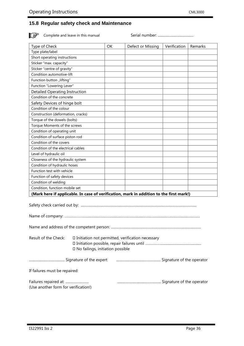
15.8 Regular safety check and Maintenance
Complete and leave in this manual Serial number: ........................................
Type of Check OK Defect or Missing Verification Remarks
Type plate/label
Short operating instructions
Sticker “max. capacity”
Sticker “centre of gravity”
Condition automotive-lift
Function button „lifting”
Function “Lowering Lever“
Detailed Operating Instruction
Condition of the concrete
Safety Devices of hinge bolt
Condition of the colour
Construction (deformation, cracks)
Torque of the dowels (bolts)
Torque Moments of the screws
Condition of operating unit
Condition of surface piston rod
Condition of the covers
Condition of the electrical cables
Level of hydraulic oil
Closeness of the hydraulic system
Condition of hydraulic hoses
Function test with vehicle
Function of safety devices
Condition of welding
Condition, function mobile set
(Mark here if applicable. In case of verification, mark in addition to the first mark!)
Safety check carried out by: ..................................................................................................................................
Name of company: ………………....................................................................................................................................
Name and address of the competent person: .....................................................................................................
Result of the Check: � Initiation not permitted, verification necessary
� Initiation possible, repair failures until ……………..............................................
� No failings, initiation possible
........................................ Signature of the expert .................................................. Signature of the operator
If failures must be repaired:
Failures repaired at: .......................... ................................................. Signature of the operator
(Use another form for verification!)

Operating Instructions CML3000
I322991 Iss 2 Page 37
15.9 Regular safety check and Maintenance
Complete and leave in this manual Serial number: ........................................
Type of Check OK Defect or Missing Verification Remarks
Type plate/label
Short operating instructions
Sticker “max. capacity”
Sticker “centre of gravity”
Condition automotive-lift
Function button „lifting”
Function “Lowering Lever“
Detailed Operating Instruction
Condition of the concrete
Safety Devices of hinge bolt
Condition of the colour
Construction (deformation, cracks)
Torque of the dowels (bolts)
Torque Moments of the screws
Condition of operating unit
Condition of surface piston rod
Condition of the covers
Condition of the electrical cables
Level of hydraulic oil
Closeness of the hydraulic system
Condition of hydraulic hoses
Function test with vehicle
Function of safety devices
Condition of welding
Condition, function mobile set
(Mark here if applicable. In case of verification, mark in addition to the first mark!)
Safety check carried out by: ..................................................................................................................................
Name of company: ………………....................................................................................................................................
Name and address of the competent person: .....................................................................................................
Result of the Check: � Initiation not permitted, verification necessary
� Initiation possible, repair failures until ……………..............................................
� No failings, initiation possible
........................................ Signature of the expert .................................................. Signature of the operator
If failures must be repaired:
Failures repaired at: .......................... ................................................. Signature of the operator
(Use another form for verification!)

Operating Instructions CML3000
I322991 Iss 2 Page 38
15.10 Extraordinary safety check and Maintenance
Complete and leave in this manual Serial number: ........................................
Type of Check OK Defect or Missing Verification Remarks
Type plate/label
Short operating instructions
Sticker “max. capacity”
Sticker “centre of gravity”
Condition automotive-lift
Function button „lifting”
Function “Lowering Lever“
Detailed Operating Instruction
Condition of the concrete
Safety Devices of hinge bolt
Condition of the colour
Construction (deformation, cracks)
Torque of the dowels (bolts)
Torque Moments of the screws
Condition of operating unit
Condition of surface piston rod
Condition of the covers
Condition of the electrical cables
Level of hydraulic oil
Closeness of the hydraulic system
Condition of hydraulic hoses
Function test with vehicle
Function of safety devices
Condition of welding
Condition, function mobile set
(Mark here if applicable. In case of verification, mark in addition to the first mark!)
Safety check carried out by: ..................................................................................................................................
Name of company: ………………....................................................................................................................................
Name and address of the competent person: .....................................................................................................
Result of the Check: � Initiation not permitted, verification necessary
� Initiation possible, repair failures until ……………..............................................
� No failings, initiation possible
........................................ Signature of the expert .................................................. Signature of the operator
If failures must be repaired:
Failures repaired at: .......................... ................................................. Signature of the operator
(Use another form for verification!)

Operating Instructions CML3000
I322991 Iss 2 Page 39
16 AFTER SALES SERVICE
Apart from the routine maintenance and adjustments stipulated in this manual the equipment must
not be tampered with in any way. All further servicing must be carried out only by an engineer from
an Authorised Agent. Failure to observe these conditions will invalidate the Guarantee.
16.1 On-Site Service / Overhaul / Spare Parts
If you require a Service Engineer to attend ON SITE, either due to an equipment fault, or for
machine calibration, or if the equipment covered by this manual requires to be sent back for
factory overhaul, or if you need spare parts, please contact our Product Support Department
Outside UK mainland
Service for export customers are provided by the agent from whom your equipment was
purchased.
UK After-Sales Service
Call Crypton Support for details of local service agents.
Technical Information
Crypton also provide information and contracts covering:
Car Data, Fault Code Information, Diagnostic Information, Software Support Contracts,
Software Updates & Accessories.
16.2 CONTACT DETAILS
Contact UK Sales on 0844 665 7613
Email [email protected]
Contact Support – 0844 665 7610
Support Fax - UK 0844 665 7604
Email [email protected]
Continental Automotive Trading UK Ltd
36 Gravelly Industrial Park
Birmingham B24 8TA
United Kingdom
www.cryptontechnology.com
Crypton - A Brand of the Continental Corporation
E & O E. The Company reserves the right to introduce improvements in design or specification without prior notice.
The sale of this product is subject to our standard terms, conditions and relevant product warranty