crosstakl 2002 cmmi feb02
TRANSCRIPT

8/8/2019 CROSSTAKL 2002 CMMI feb02
http://slidepdf.com/reader/full/crosstakl-2002-cmmi-feb02 1/32
8/8/2019 CROSSTAKL 2002 CMMI feb02
http://slidepdf.com/reader/full/crosstakl-2002-cmmi-feb02 2/32
CMMI Version 1.1: What Has Changed? This article describes key changes to the new version of the Capability Maturity ModelIntegration product suite, including discoveries made in pilot assessments.by Mike Phillips
CMMI Appraisal Methodologies: Choosing What Is Right For You The keys to developing an appraisal tool kit from among the three classes of appraisalmethods are education, preparation, and pre-work.by Ilene Minnich
To CMMI or Not to CMMI: Issues to Think About This article describes a number of scenarios to give you an idea of what issues and prob-lems you will face in developing your CMMI adoption strategy.by Winifred Menezes
Transitioning From SA-CMM to CMMI in the Special Operations ForcesSystems Program Office
A pilot organization for the Capability Maturity Model Integration-Acquisition explains itsswitch to this model, and what they learned during its appraisal.by Donald R. Michels and Bonnie Bollinger
How Do I Make My Organization Comply With Yet Another New Model?
If you are already using a model, this author says that adopting a new model should be approachedas mapping and modifying rather than as starting over.by Sarah A. Sheard
How Function Points Support the Capability Maturity Model Integration This article demonstrates the direct connection between the CMMI and function points and themutual effect of increased process maturity.by Carol Dekkers and Barbara Emmons
U.S.Army Develops High Quality, Extremely Low Cost Digital Message ParserHere is how one directorate successfully developed a highly automated process with high quality ata low cost by virtue of their development process.by Edgar Dalrymple
CrossTalk
Kent Bingham,
Digital Illustration
and Design, is aself-taught graphic
artist/designer whofree-lances print
and Web design
projects.
3
14
27
28
30
31
DeparDepar tmentstments Article Submissions: We welcome articles of interest to thedefense software community.Articles must be approved by theCROSSTALK editorial board prior to publication. Please fol-low the Author Guidelines, available at www.stsc.hill.af.mil/crosstalk/xtlkguid.pdf.CROSSTALKdoes not pay for submis-sions. Articles published in CROSSTALK remain the proper-ty of the authors and may be submitted to other publications.
Reprints and Permissions: Requests for reprints must berequested from the author or the copyright holder. Pleasecoordinate your request with CROSSTALK.
Trademarks and Endorsements: This DoD journal is anauthorized publication for members of the Department of Defense. Contents of CROSSTALK are not necessarily theofficial views of, or endorsed by, the government, theDepartment of Defense, or the Software Technology Support
Center. All product names referenced in this issue are trade-marks of their companies.
Coming Events:We often list conferences, seminars, sympo-siums,etc. that are of interest to our readers.There is no feefor this service, but we must receive the information at least90 days before registration. Send an announcement to theCROSSTALK Editorial Department.
STSC Online Services: www.stsc.hill.af.milCall (801) 777-7026, e-mail: [email protected]
Back Issues Available: The STSC sometimes has extra copiesof back issues of CROSSTALK available free of charge.
The Software Technology Support Center was establishedat Ogden Air Logistics Center (AFMC) by Headquarters U.S.Air Force to help Air Force software organizations identify,evaluate, and adopt technologies to improve the quality of theirsoftware products,efficiency in producing them, and their abil-ity to accurately predict the cost and schedule of their deliv-ery.
SPONSOR
PUBLISHER
ASSOCIATE
PUBLISHER
MANAGING EDITOR
ARTICLE
COORDINATOR
CREATIVE SERVICESCOORDINATOR
PHONE
FAX
CROSSTALK ONLINE
CRSIP ONLINE
Lt.Col. Glenn A. Palmer
Tracy Stauder
Elizabeth Starrett
Pamela Bowers
Nicole Kentta
Janna Kay Jensen
(801) 586-0095(801) [email protected]/crosstalk/crostalk.html
www.crsip.hill.af.mil
Subscriptions: Send correspondence concerningsubscriptions and changes of address to the followingaddress.You may e-mail or use the form on p. 24.
Ogden ALC/TISE7278 Fourth St.Hill AFB, UT 84056-5205
CaCapabilitypability MaturityMaturity ModelModel IntegrationIntegration
ON THE COVER
2 CROSSTALK The Journal of Defense Software Engineering February 2002
4
7
9
12
15
21
25
SoftwarSoftwaree EngineeringEngineering TTechnoloechnologgyy
From the Publisher
Coming Events
Web Sites
STC 2002 Announcement
Letters to the Editor
BackTalk
FieldField ReporReportt

8/8/2019 CROSSTAKL 2002 CMMI feb02
http://slidepdf.com/reader/full/crosstakl-2002-cmmi-feb02 3/32
H. Bruce AllgoodDeputy Director, Computer Resources Support Improvement Program
This issue of CrossTalk is the second dedicated to the Capability Maturity Model®
IntegrationSM (CMMISM ) project. Readers new to CMMI will find it useful to first review the CMMI articles found in the July 2000 CrossTalk. Back issues can be found online atthe Software Technology Support Center (STSC) Web site <www.stsc.hill.af.mil>. After more
than an additional year of comments and piloting, CMMI Version 1.1 was released in January 2002. The focus has now turned to “implementation” of CMMI into broader usage in indus-try and the government. Our Air Force program office (Computer Resources Support
Improvement Program) remains dedicated to the successful introduction of CMMI into governmentoffices throughout the Department of Defense and other government agencies.
I hope that most people now recognize that CMMI is a cooperative endeavor between government,industry, and the Software Engineering Institute. The goal of the CMMI project starting in early 1998has been to merge several separate discipline process improvement models into a single framework thatcan be used as a basis for a common approach to process improvement for both systems and softwareengineering. It is also expected that CMMI will provide for new disciplines to be added with relative ease.It is anticipated that CMMI Version 1.1 will prove to be as stable and long-lived as the source model forsoftware that preceded it.
The first CMMI Technology Conference and User Group was held at the Denver Technology Center, Nov. 13-15, 2001. More than 300 individuals met to share lessons learned in the early imple-
mentations of CMMI. Full details of the presentations from this conference can be downloaded fromthe National Defense Industrial Association Conferences Web site: <www.dtic.mil/ndia/2001cmmi/2001cmmi.html>.
In this issue of CrossTalk, CMMI Project Manager Mike Phillips describes in CMMI Version 1.1: What Has Changed? the key changes that have occurred with the release of CMMI Version 1.1. One of the biggest concerns voiced about the new CMMI model has been the length of time required forappraisals using this larger, combined model. Phillips also describes some of the discoveries that havebeen made from eight pilot appraisals accomplished in the Phase II Pilot Program, including improvedefficiency in the execution of the appraisal method. In CMMI Appraisal Methodologies: Choosing What Is Right for You , Ilene Minnich discusses some alternatives to using the full class A Standard CMMI
Appraisal Method for Process Improvement (SCAMPI). She also stresses that “the keys to success areeducation, preparation, and pre-work.”
As mentioned above,one of the goals was to make the CMMI framework easily expandable for new discipline investigations. Donald R. Michels and Bonnie Bollinger from Warner Robins Air LogisticsCenter review the success that they have achieved by piloting new acquisition process areas inTransitioning From SA-CMM to CMMI in the Special Operations Forces Systems Program Office .
Consultant Winifred Menezes discusses in To CMMI or Not to CMMI: Issues to Think About someideas for transitioning to CMMI from several different perspectives. In How Function Points Support the Capability Maturity Model Integration , Barbara Emmons and Carol Dekkers discuss the tie between CMMIprocess areas and Function Point Analysis. They indicate that this tie is not well known,but make a com-pelling case that a direct connection does exist.
Also included is an article by Sarah Sheard, How Do I Make My Organization Comply With Yet Another New Model? Sheard believes that complying with a new capability model is much easier than starting freshif the organization already complies with another model. Lastly an article by Edgar Dalrymple, U.S.
Army Develops High Quality, Extremely Low Cost Digital Message Parser , details how the Software Engineering Directorate, by virtue of their development process, successfully provided a key technology to supportone of the Army’s most significant organizational goals: interoperability via digitization.
Space limitations in this issue forced an article by Suzanne Garcia of the Software Engineering Institute, Are You Prepared for CMMI? , to be published in next month’s issue. Garcia talks about how applying technology adoption concepts can smooth the CMMI adoption process considerably.
I hope that these articles, as well as additional ones about CMMI usage over the coming year, willprovide incentive for your organization to get started or continue in your voyage to migrate to CMMI.For more detailed information on the CMMI project visit the SEI Web site at<www.sei.cmu.edu/cmmi>. For assistance in understanding and getting started with CMMI, also visitthe STSC Web site at <www.stsc.hill.af.mil>.
From the Publisher
February 2002 www.stsc.hill.af.mil 3
Updated CMMI Focuses on Broader Usagein Industry and Government

8/8/2019 CROSSTAKL 2002 CMMI feb02
http://slidepdf.com/reader/full/crosstakl-2002-cmmi-feb02 4/324 CROSSTALK The Journal of Defense Software Engineering February 2002
Since 1991, Capability Maturity Models®
(CMM® ) have been developed for a variety of disciplines, including systemsengineering, software engineering, soft- ware acquisition, work-force practices,and integrated product and process devel-opment. These models have been valuableto many organizations; however, the useof multiple models has been expensiveand complicated. Organizations that wantto pursue process improvement acrossdisciplines have had to cope with differ-ences in model architecture, content,and approach. These differences havelimited these organizations’ ability tofocus their improvement successfully. Applying multiple models that are notintegrated is costly in terms of training,assessments, and improvement activi-ties.
The Capability Maturity Model®
IntegrationSM (CMMISM ) project was initi-ated to address these problems. Figure 1shows how integrating material into the
CMMI models adds up as you comparethe number of model elements in disci-pline-specific models to those in CMMImodels.
CMMI is sponsored by the U.S.Department of Defense Office of theUnder Secretary of Defense, Acquisition, Technology, and Logistics and theSystems Engineering Committee of theNational Defense Industrial Association. The CMMI project has been developing aproduct suite, including CMMI models,appraisal method, and training, since 1998. Version 1.0 (V1.0) was released in August
2000 and Version 1.1 (V1.1) was releasedin January 2002. During the next few years, V1.1 will remain stable. No updatesare planned for the next three years.
The experience gained in launching the Software CMM (SW-CMM® ) in theearly 1990’s led the CMMI project tomove fairly quickly from a V1.0 to a V1.1. We felt we had an initial operating capa-
bility with V1.0, but needed to commitresources to reach a final operating capa-bil ity of the baseline models. Thisapproach drove the decision to have a for-mal public review period early in 2001 togather initial user input. This was thencoupled with a second phase of pilotsusing the model before publishing updates of the CMMI models and theStandard CMMISM Appraisal Method forProcess Improvement (SCAMPISM )method.
We created a Change Control Board(CCB) populated with experts fromacross government and industry as well asthe Software Engineering Institute (SEI).Guidelines were established to limit V1.1changes to those addressing changerequests (CRs) that identified elementsthat were “broken.” This meant that we would not restructure the model, nor add
material for new elements beyond those in V1.0. CRs that called for new processareas or combining process areas weredeferred because they would result inmore change than we wished to see for V1.1.
Probably the most controversial deci-sion made for V1.1 was to maintain tworepresentations, or architectures, of theCMMI model [1]. The systems engineer-ing and software engineering communitiesthat had grown accustomed to two con-trasting architectures for their respective
discipline-specific models felt it best tomaintain both the continuous representa-tion from the Electronic Industries Alliance/Interim Standard (EIA/IS) 731heritage and the staged representationfrom the SW-CMM heritage [2]. As theCMMI models have evolved, the modelcontent has remained consistent for bothcontinuous and staged representations.
V1.1 Themes: Stability andUsabilityStability of the CMMI Product Suiterefers to maintaining essential content andstructure while evolving the products toimprove quality. We knew this theme wascritical to users considering transition so
they would have a relatively unchangingproduct for building their transitionplans [3]. We knew that early users ofthe CMMI Product Suite would
uncover some need for clarificationsand improvements [4]. However, we
gained confidence from comments duringlater pilot tests that the V1.0 material wasin fact, ready for operational use Therefore, to promote transition and topreserve the investment of early adoptersthe decision was made to focus V1.1changes primarily on corrections oferrors and essential clarifications that were designed to avoid confusion. Thmulti-organizational CCB has helpedmaintain an approach that honorsrequests for clarification with minimalimpact to the “required” and “expected”elements of CMMI models.
CMMI stability could have been fullypreserved by making no changes to theproduct suite after the CMMI V1.0release, but usability considerations dictat-ed otherwise. The CRs confirmed what we suspected – a group of authors from various backgrounds and environment writing documents for users with variousbackgrounds and environments used words and phrases that sometimes neededto be clarified. Without that clarificationprocess improvement groups and apprais-al teams may spend valuable time on inter-
CMMI Version1.1: What Has Changed?
Mike PhillipsSoftware Engineering Institute
With Capability Maturity Model ® Integration SM (CMMI SM ) V1.1, we have improved the “initial use” version provided to
the community in the fall of 2000. The purpose of this article is to describe the key changes to the CMMI product suite,with some of the discoveries we made along the way.
Capability Maturity Model Integration
® Capability Maturity Model and CMM are registered in theU.S. Patent and Trademark Office.
SM CMMI, CMM Integration, SCAMPI, SCAMPI Lead Assessor, and SCE are service marks of Carnegie MellonUniversity.
“ The multi-organizational
CCB has helped maintain
an approach that honors
requests for clarification
with minimal impact to
the ‘required’ and
‘expected’ elements of
CMMI models.”

8/8/2019 CROSSTAKL 2002 CMMI feb02
http://slidepdf.com/reader/full/crosstakl-2002-cmmi-feb02 5/32February 2002 www.stsc.hill.af.mil 5
CMMI Version 1.1: What Has Changed
pretation that would clearly be betterspent on improvement or its validation. We found that every process area hadsome room for such improvement. Someprocess areas such as Process and ProductQuality Assurance had relatively few defi-ciencies. Others, particularly those thatreflected more cross-discipline integra-tion, showed a greater need for explanato-ry statements. Clarifications have
improved the usability of the model with-out adversely affecting its stability.
Model Changes Equal Greater
Clarity The initial CR reviews brought confi-dence that most corrections could bemade in informative material, rather thanacross the required and expected elementsof the model. In the end, only one goal was deleted by a restructuring of theOrganizational Process Definitionprocess area. Three other goals have been
changed or clarified: one each in theOrganizational Training, TechnicalSolution, and Product Integration processareas. At the practice level, about 10 per-cent had wording clarifications, and twopractices were deleted.
The V1.1 models have retained thesame process areas. Further, these processareas belong to the same process area cat-egories as V1.0 of the continuous repre-sentation, and to the same maturity levelsas V1.0 of the staged representation.Figure 2 shows a high-level summary of
V1.1 process areas and their position ineach representation.Most of the changes have focused on
assuring that key terms are used consis-tently throughout all the models. “Processcapability” is a typical example. The termhas a specific meaning for experts in sta-tistical process control, but it oftenseemed appropriate to describe improve-ments in the capability dimension of thecontinuous representation. In V1.1, only the statistical meaning is used. Similarclarifications were provided for termssuch as “life cycle,” “process,” and
“process area.”Relationships across the engineering
process areas were clarified. Of note wasthe elimination of the overlap between“make-or-buy” analysis in the TechnicalSolution and Supplier AgreementManagement process areas. Greater atten-tion to architectural analysis and design was requested in CRs, and an enhancedspecific practice addressed this area.
Generic practice (GP) content wasstrengthened for V1.1. Improved elabora-tions are now provided for “Plan the
Process” (GP 2.2), “Provide Resources”(GP 2.3), and “Monitor and Control theProcess” (GP 2.8). Model authors alsoclarified the relationship of several of theGPs to their associated process areasbased on feedback from some of the pilotappraisals using the continuous represen-tation.
Some terms were replaced with moreappropriate substitutes. “Capture” wasreplaced with “document” or “record.”“Process capability model” was replaced, where appropriate, with “process per-formance model.” And, as will be evidentin the following section, we replaced theterm “assessment” with “appraisal” asappropriate.
Appraisal Changes: A Shift inApproachOne of the significant additions to CMMI V1.1 is a single, common method forexternal evaluations as well as internalappraisals for process improvement.Because of the strong correlation of theSoftware Capability Evaluation (SCESM ) V3.0 with the familiar CMM-Based Appraisal for Internal ProcessImprovement, the SCE was chosen as asource document for the new CMMIMethod Description Document. A sepa-
rate implementation guide for sourceselection and contract monitoring will alsobe provided to describe the unique char-acteristics of an appraisal when this kindof external use is planned.
The other key effort that the appraisalteam undertook was to apply “lessonslearned” from the community. Two key concepts are now part of the V1.1 release.First, the idea of “triage” has been moreexplicitly described. This description hasthe appraisal team focusing more of theirattention on the areas of greater uncer-
tainty and moving quickly through theprocess areas where clear evidence hasbeen delivered. Second, when conductingan appraisal, the appraisal team will clearlyexpect that the appraised organization hasdone its homework to prepare for the visit The materials provided by the appraisedorganization will be used from the begin-ning of the appraisal, so that the appraisateam’s effort shifts from a “discovery”approach to a “verify and validate”approach. Pilot use of these approacheshas shown marked improvement in thetime required to assure goal satisfaction.
Release PAs/ Goals/ Activities/FAs Themes* Practices**
SW-CMM V1.1 18 52 316
SW-CMM V2C 19 62 318
EIA/IS 731 19 77 383
IPD-CMM V0.98 23 60 865
CMMI V1.0 SE/SW 22 70 417
CMMI V1.0 SE/SW/IPPD 24 76 460
* Ratable components** Key to implementation effort
61 1566199
CMMI V1.1 SE/SW/IPPD 24 75 458
Figure 1: Model Measures
Level Focus Process Areas
5 Optimizing Continuous
Process
Improvement
Organizational Innovation and Deployment
Causal Analysis and Resolution
4 Quantitatively
Managed
Quantitative
Management
Organizational Process Performance
Quantitative Project Management
3 Defined Process
Standardization
Requirements Development
Technical Solution
Product Integration
Verification
Validation
Organizational Process Focus
Organizational Process Definition
Organizational Training
Integrated Project Management
Risk Management
Decision Analysis and Resolution
Organizational Environment for Integration (IPPD
Integrated Teaming (IPPD)
2 Managed Basic Project
Management
Requirements Management
Project Planning
Project Monitoring and Control
Supplier Agreement Management
Measurement and Analysis
Process and Product Quality Assurance
Configuration Management
1 Initial
STAGED REPRESENTATION
Figure 2: CMMI Process Areas
Category Process Areas
Process Organizational Process Focus
Management Organizational Process Definition
Organizational Training
Organizational Process Performance
Organizational Innovation and Deployment
Project Project Planning
Management Project Monitoring and Control
Supplier Agreement Management
Integrated Project Management
Risk Management
Quantitative Project Management
Integrated Teaming (IPPD)
Engineering Requirements Management
Requirements Development
Technical Solution
Product Integration
Verification
Validation
Support Configuration Management
Process and Product Quality Assurance
Measurement and Analysis
Causal Analysis and Resolution
Decision Analysis and Resolution
Organizational Environment for Integration (IPPD
CONTINUOUS REPRESENTATION

8/8/2019 CROSSTAKL 2002 CMMI feb02
http://slidepdf.com/reader/full/crosstakl-2002-cmmi-feb02 6/32
Version 1.1 TrainingBecause most of the changes to themodel approved for V1.1 are in theinformative material, few changes will berequired to the training slides for CMMIcourses [5]. More significant is the work required to assure that all of the instruc-tors of the revised material understandthe clarifications that were made so thatthey can effectively teach the revisedmaterial. We do not envision any need toprovide “delta” training to those whohave taken the V1.0 courses. Those whohave attended V1.0 courses may wish toprint a copy of the model version com-parison document we have provided. The Word document with redlines can befound in the “CMMI Models” section of theCMMI Web site <www.sei.cmu.edu/cmmi/>.
Discoveries from the PilotsIn October 2000, a call for participation was issued for the Phase II Pilot Program
to gather experiences using V1.0. Eightpilot tests were conducted. The appraisalmethod used was SCAMPI V1.0 withsome experimental variations intended toimprove the efficiency of the method.Phase II pilots included observers fromthe CMMI project who collected meas-urements to gauge progress against thedefined appraisal goal of 100 hours.Observers used this goal, 100 hours or 5.7hours per process area, for the on-siteperiod of a SCAMPI appraisal using theCMMI model for Systems Engineering and Software Engineering (CMMI-SE/SW), with the 18 process areas thatdefine Target Profile 3 or, equivalently,Maturity Level 3.
Across the eight pilot appraisals, anaverage of 5.3 hours per process area dur-ing the on-site period was achievedagainst the objective of 5.7 hours perprocess area. In particular, SCAMPIpilots using improved data gathering with validating interviews achieved 5.0 hoursper process area. This method, involving additional pre-on-site review of objectiveevidence, has been included as an
improved technique in SCAMPI V1.1.Other pilot test results reinforced pre-
viously known best practices for appraisalconduct. In particular, the importance of appraisal preparation, model training, andin-depth model comprehension by theappraisal team cannot be overempha-sized. Given the newness of the CMMImodels and appraisal method, no one had vast amounts of experience with theiruse. However, those with a working knowledge attained from prior appraisalsor transition experience (e.g., mapping of
the model to command media) were moreadept at applying the model during aSCAMPI.
Sunset Legacy Models The CMMI Product Suite is intended togradually replace the SW-CMM andEIA/IS-731. The approaches being takento sunset these two models are consistent.
The SEI plans no further updates tothe SW-CMM model, appraisal methods,and training. After December 2003, theSEI will no longer provide public offer-ings of “Introduction to SW-CMM”training, although the SEI and SW-CMMtransition partners may continue to deliv-er the training to select organizations. Also after December 2003, SW-CMMappraiser and evaluator training will nolonger be offered. Therefore, active SW-CMM appraisers and evaluators will needto transition to CMMI SCAMPI appraiserstatus by December 2005. SCAMPI will
then be the appraisal method of choice. The Government Electronic Industry
Association G-47 committee, the origina-tor of EIA/IS 731, has taken a similarapproach. No further updates are plannedfor this interim standard. The InterimStatus has been renewed to cover thetransition period while the CMMIProduct Suite is being adopted, but nofurther extensions are currently envi-sioned.
Summary
The year 2001 has been a remarkable yearfor the CMMI Product Suite. Theimprovement to the product suite fromreviews and rewrites will be obvious to theusing community as it begins reading andusing CMMI materials. Now we look for- ward to working with you to ease adoptionof this even better model that builds uponand integrates the firm process improve-ment framework of the legacy models.
References1. Shrum, S. “Choosing a CMMI Model
Representation,” <www.stsc.hill.af.mil/
crosstalk/2000/jul/shrum.asp>, Oct.2001.
2. SEI. Capability Maturity Model® (SW-CMM® ) for Software, <www.sei.cmu.edu/cmm>, Sept. 2001a.
3. SEI. CMMISM Publications and Transition Materials, <www.sei.cmu.edu/cmmi/publications/pubs.html>,Sept. 2001f.
4. SEI. CMMISM Product Suite,<www.sei.cmu.edu/cmmi/products/products.html>, Sept. 2001e.
5. SEI. Education and Training Courses,
<www.sei.cmu.edu/products/courses/courses.html>, Sept. 2001d.
Additional Reading1. SEI. Systems Engineering Capability
Maturity Model®, <www.sei.cmu.edu/cmm/se-cmm.html>, Sept. 2001b.
2. SEI. CMMISM Tutorial, <www.seicmu.edu/cmmi/publications/stc.presentations/tutorial.html>, Sept. 2001c
3. SEI. Software EngineeringInformation Repository, <http://seirsei.cmu.edu>, Sept. 2001g.
4. SEI. Technology Adoption, <www.seicmu.edu/adopting/adopting.html>Oct. 2001h.
5. SEI. “Bibliography on IntegratedProduct and Process Development,”<www.sei.cmu.edu/cmmi/publications/ippd-biblio.html>, Nov. 2001i.
Publisher’s NoteCrossTalk ’s parent organization, theSoftware Technology Support Center (STSC), isa technology transition partner with the Software Engineering Institute (SEI). Organizations newto software process improvement or to the CMMIcan receive additional help with understanding theinformation from the SEI and their technologytransition partners at the STSC’s and other Websites listed on page 27.
About the Author
Mike Phillips is director of SpecialProjects at the Software Engineering Institute (SEI), a position created tolead the Capability Maturity Model®
IntegrationSM project for the SEI andthe steering group. He was previously responsible for transition enabling activities at the SEI. Prior to his retire-ment as a colonel from the Air Force,he managed the $36 billion develop-ment program for the B-2 in the B-2Special Programs Office and com-manded the 4950th Test Wing at Wright-Patterson AFB, Ohio. Phillipshas a bachelor's degree from the AirForce Academy, and master’s degreesfrom Georgia Tech, from theUniversity of Southern California, andfrom Salve Regina College and theNaval War College.
4500 Fifth Ave.
Pittsburgh, PA 15213
Phone: (412) 268-5884
Fax: (412) 268-5758
E-mail: [email protected]
6 CROSSTALK The Journal of Defense Software Engineering February 2002
Capability Maturity Model Integration
8/8/2019 CROSSTAKL 2002 CMMI feb02
http://slidepdf.com/reader/full/crosstakl-2002-cmmi-feb02 7/32February 2002 www.stsc.hill.af.mil 7
Starting with the Appraisal Requirementsfor Capability Maturity Model®
(CMM® ) IntegrationSM (CMMISM ) (ARC) Version 1.0 [1], the authors of the CMMIproduct suite laid out the requirements forthree classes of appraisal methods. This isimportant because it recognizes that anorganization can get benefits from internalappraisals at various levels of resourceexpenditures.
Of course this has always been true,but the ARC formalizes the threeclasses by mapping requirements tothem, which provides a consistency andstandardization that has not been avail-able with any of the CMMI predecessormodels. It also allows organizations thefreedom to develop an appraisalmethodology that works best for theirorganization, and once mapped to the ARC appraisal classes, the results of any
appraisal can be easily benchmarkedagainst other appraisals from the sameclass.
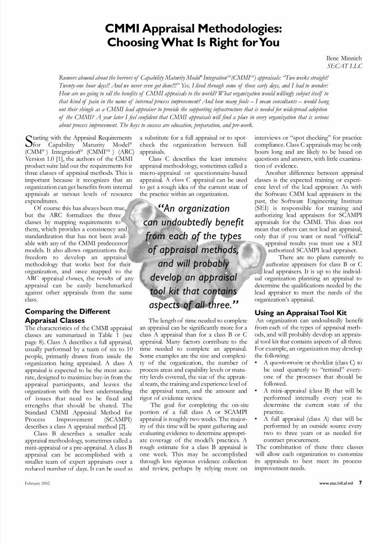
Comparing the DifferentAppraisal Classes The characteristics of the CMMI appraisalclasses are summarized in Table 1 (seepage 8). Class A describes a full appraisal,usually performed by a team of six to 10people, primarily drawn from inside theorganization being appraised. A class Aappraisal is expected to be the most accu-rate, designed to maximize buy-in from the
appraisal participants, and leaves theorganization with the best understanding of issues that need to be fixed andstrengths that should be shared. TheStandard CMMI Appraisal Method forProcess Improvement (SCAMPI)describes a class A appraisal method [2].
Class B describes a smaller scaleappraisal methodology, sometimes called amini-appraisal or a pre-appraisal. A class Bappraisal can be accomplished with asmaller team of expert appraisers over areduced number of days. It can be used as
a substitute for a full appraisal or to spot-check the organization between fullappraisals.
Class C describes the least intensiveappraisal methodology, sometimes called amicro-appraisal or questionnaire-basedappraisal. A class C appraisal can be usedto get a rough idea of the current state of the practice within an organization.
The length of time needed to completean appraisal can be significantly more for aclass A appraisal than for a class B or Cappraisal. Many factors contribute to thetime needed to complete an appraisal.Some examples are the size and complexi-ty of the organization, the number of process areas and capability levels or matu-rity levels covered, the size of the apprais-
al team, the training and experience level of the appraisal team, and the amount andrigor of evidence review.
The goal for completing the on-siteportion of a full class A or SCAMPIappraisal is roughly two weeks. The major-ity of this time will be spent gathering andevaluating evidence to determine appropri-ate coverage of the model’s practices. Arough estimate for a class B appraisal isone week. This may be accomplishedthrough less rigorous evidence collectionand review, perhaps by relying more on
interviews or “spot checking” for practicecompliance. Class C appraisals may be onlyhours long and are likely to be based onquestions and answers, with little examina-tion of evidence.
Another difference between appraisaclasses is the expected training or experi-ence level of the lead appraiser. As withthe Software CMM lead appraisers in thepast, the Software Engineering Institute(SEI) is responsible for training andauthorizing lead appraisers for SCAMPIappraisals for the CMMI. This does notmean that others can not lead an appraisalonly that if you want or need “official”
appraisal results you must use a SEIauthorized SCAMPI lead appraiser.
There are no plans currently toauthorize appraisers for class B or C
lead appraisers. It is up to the individ-ual organization planning an appraisal to
determine the qualifications needed by thelead appraiser to meet the needs of theorganization’s appraisal.
Using an Appraisal Tool Kit An organization can undoubtedly benefifrom each of the types of appraisal meth-ods, and will probably develop an apprais-al tool kit that contains aspects of all threeFor example, an organization may developthe following:• A questionnaire or checklist (class C) to
be used quarterly to “remind” every-one of the processes that should be
followed.• A mini-appraisal (class B) that will be
performed internally every year todetermine the current state of thepractice.
• A full appraisal (class A) that will beperformed by an outside source everytwo to three years or as needed forcontract procurement.
The combination of these three classe will allow each organization to customizeits appraisals to best meet its processimprovement needs.
CMMI Appraisal Methodologies:Choosing What Is Right for You
Ilene MinnichSECAT LLC
Rumors abound about the horrors of Capability Maturity Model ® Integration SM (CMMI SM ) appraisals: “Two weeks straight! Twenty-one hour days!! And we never even got done!!!” Yes, I lived through some of those early days, and I had to wonder:
How are we going to sell the benefits of CMMI appraisals to the world? What organization would willingly subject itself tothat kind of pain in the name of internal process improvement? And how many fools – I mean consultants – would hang
out their shingle as a CMMI lead appraiser to provide the supporting infrastructure that is needed for widespread adoption
of the CMMI? A year later I feel confident that CMMI appraisals will find a place in every organization that is serious
about process improvement. The keys to success are education, preparation, and pre-work.
“ An organization
can undoubtedly benefit
from each of the types
of appraisal methods,
and will probably
develop an appraisal
tool kit that contains
aspects of all three.”
8/8/2019 CROSSTAKL 2002 CMMI feb02
http://slidepdf.com/reader/full/crosstakl-2002-cmmi-feb02 8/328 CROSSTALK The Journal of Defense Software Engineering January 2002
Reducing Appraisal PainPreparation for the appraisal always plays abig part in its success. As with all of the
predecessors to CMMI, the definition of the scope of the organization is probably the one decision that most affects the timeto complete the appraisal itself. SinceCMMI can be used to evaluate the activi-ties associated with systems engineering,software engineering, integrated productand process development (IPPD), andacquisition, be aware that the broader thescope of the organization the more people will be involved in the scope of theappraisal. A broader organization, or anorganization now looking at including more “disciplines,” takes more time to
appraise. This has always been true, butmany appraisal sponsors may not be awareof the obvious correlation.
Another way to lessen the pain of anappraisal is to shift as much work as possi-ble away from the “on-site” portion of theappraisal and complete it beforehand. There are many variations of this.Suggestions for appraisal pre-work includemapping the organization’s processes toCMMI, gathering and/or reviewing evi-dence, distributing and completing CMMI-based questionnaires, and developing inter-
view questions for use during the appraisal. The better the data your appraisal teamstarts with, the less time it will take theteam to complete.
Probably the biggest contributor to thesuccess of your CMMI appraisal will be inproviding your appraisal participants withthe proper level of education, especially if they have some preconceived notionsbased on the use of predecessor models. The appraisal sponsors need to have realis-tic expectations concerning the scope of the organization, the number of appraisalparticipants and their areas of expertise,and the use of each of the appraisal class-es. The appraisal team and the supporting staff responsible for the appraisal pre-
work need to understand the CMMI, therequirements and methodology for theappropriate class of appraisal, and how tomap or translate the work being performedin the organization to the CMMI. Theremainder of the appraisal participantsmost likely will not need any special CMMItraining.
Conclusion Thorough planning and pre-work of aCMMI appraisal may be more importantthan ever before, especially if your organi-
zation is planning to broaden its definitionof organization or include additional disci-plines and activities. Setting expectationseducating participants, and mapping termi-nology are key to the success of anappraisal. Developing an appraisal tool kitincluding the different appraisal classes willallow your organization to meet its processimprovement needs in an efficient andeffective manner.◆
References Note : All these documents are available onthe Web at <www.sei.cmu.edu>.1. CMMI Product Development Team
Appraisal Requirements for CMM(ARC), Version 1.0. CMU/SEI-2000- TR-011, Aug. 2000.
2. Standard CMMI Appraisal Method forProcess Improvement: MethodDescription, Version 1.0. CMU/SEI-2000-TR-009, Oct. 2000.
3. CMMI Product Development TeamCapability Maturity Model Integrationfor Systems Engineering/SoftwareEngineering/Integrated Product andProcess Development, Version 1.1Continuous Representation. CMU/SEI-2000-TR-019, Aug. 2000.
About the Author
Ilene Minnich is aSECAT LLC founding partner and has work-ed as a process improve-ment and appraisal
consultant to morethan 70 organizations
worldwide. She is a part-time visiting scientist at the Software Engineering Institute (SEI) and works with theCapability Maturity Model® (CMM® )IntegrationSM training team. She is anexperienced CMM author, appraiser,and trainer. Previously at Hughes Aircraft Company, Minnich waresponsible for the Software-CMMdeployment and conducting SystemsEngineering-CMM appraisals at all
company-wide systems engineering organizations. Minnich has a bache-lor’s of science degree from LehighUniversity and a master’s degree fromthe University of Southern California.
SECAT LLC
14742 Beach Blvd. #405
La Mirada, CA 90638
Phone: (714) 449-0423
Fax: (714) 449-0256
E-mail: [email protected]
Characteristics Class A Class B Class C
Usage Mode 1. Rigorous and in-depth investigationof process(es).
2. Basis for improvementactivities.
1. Initial (first time).2. Incremental
(partial).3. Self appraisal.
1. Quick-look.2. Incremental.
Advantages Thorough coverage;strengths andweaknesses for eachPA investigated;
robustness of methodwith consistent,repeatable results;provides objectiveview; option of ISO15504 conformance.
Organization gainsinsight into owncapability; provides astarting point, or
focuses on areas thatneed most attention;promotes buy-in.
Inexpensive, shortduration, rapidfeedback.
Disadvantages Demands significantresources.
Does not emphasizedepth of coverageand rigor, and cannotbe used for levelrating.
Provides less buy-inand ownership of results, not enoughdepth to fine tuneprocess improvementplans.
Sponsor Senior manager of organizational unit.
Any manager sponsoring a SPIprogram.
Any internalmanager.
Team Size 4-10 people plus anappraisal teamleader.
1-6 people plus anappraisal teamleader.
1-2 people plus anappraisal teamleader.
Team Qualification Experienced. Moderatelyexperienced.
Moderatelyexperienced.
Appraisal TeamLeader Requirements
Lead appraiser. Lead appraiser or person experiencedin method.
Person trained inmethod.
Team Composition External and internal. External or internal. External or internal.
Table 1: Characteristics of CMMI Appraisal Classes [1]
Capability Maturity Model Integration

8/8/2019 CROSSTAKL 2002 CMMI feb02
http://slidepdf.com/reader/full/crosstakl-2002-cmmi-feb02 9/32 January 2002 www.stsc.hill.af.mil 9
The Capability Maturity Model®
(CMM® ) IntegrationSM (CMMISM ) inits present form is a collection of bestpractices for the “development and main-tenance” of both “products and servic-es.” The model was developed by inte-grating practices from four differentCMMs – the “source models:” the CMMfor software, for systems engineering, forintegrated product development (IPD),and for acquisition.
Organizations can use the model asa guide for improving their ability todevelop (or maintain) products (andservices) on time, within budget, and with desired quality. During the pastdecade many organizations have usedCMM and CMM-like concepts to bring order to their software developmentprocesses. The CMMI allows these
organizations to continue focusing only on the discipline of software.
Additionally, it also provides theseorganizations the framework for enlarg-ing the focus of process improvement toother areas that also effect product devel-opment – the discipline of systems engi-neering. During the past decade, new andeffective concepts for organizing devel-opmental work have surfaced and beenadopted such as concurrent engineering or the use of integrated teams.Organizations using (or wishing to adoptthese ideas) can also find support in theCMMI by using the model with integrat-ed product and process development(IPPD) additions.
Finally, organizations that acquirecomponents or services as a substantialpart of development will find the acquisi-tion additions useful. (CMMI-SystemsEngineering (SE)/Software Engineering (SW)/IPPD/Acquisition (A) Version1.02d draft is available for review andpiloting.) CMMI-SE/SW, CMMI-SE/SW/IPPD as well as CMMI-SE/SW/IPPD/A are available at the
Software Engineering Institute’s (SEI) Web site <www.sei.cmu.edu/cmmi>.
Representations The CMMI has yet another complexity toit: the representations, staged and contin-uous. Philosophically there are two dif-ferent approaches to process improve-ment. One focuses on the organization asa whole and provides a road map of suc-
cessive stages aimed at improving theorganization’s ability to understand andcontrol its processes. This approach isthe basis for the staged representation.
The other approach focuses on indi- vidual processes, allowing the organiza-tion to choose which process or a set of processes need to have more capability.
This is the approach of the continuousrepresentation.
In theory the choice of processes isunconstrained, but in reality increasing the capability of a particular processnecessitates that other processes havecertain capabilities. So the continuousrepresentation provides a few moreroutes on the process improvement map. We are talking of two representations – two different views of the same content. The rules for converting one representa-tion into the other have been defined. So
a choice of one representation does nopreclude the use of another at a latertime.
Scenario 1:You Market aProduct That Contains
Software Your organization develops and marketa product or a product component thatcontains software, for example a cellphone or the breaking system for auto-mobiles. During the past decade, you real-ized that software was a key enabling partof your product; you have been using theSoftware CMM (SW-CMM) for some
years now. In fact some units havebeen appraised at CMM Level 3, andsay they have managed to reduce agood deal of rework.
Should you transition to theCMMI? SEI, who is the custodian ofboth the SW-CMM and the CMMI, says it will not support the SW-CMM after theyear 2003. This pronouncement does nomean the SW-CMM will disappear, butthe infrastructure that supports its use(e.g. training, authorization of assessors) will definitely be weakened.
However, there is another more com-pelling reason to transition to the CMMIOne of the source models that theCMMI was based on was the SW-CMM Version 2 Draft C. This version of th
SW-CMM was an improvement on Version 1.1, which is what you and mostother people are using. So the CMMIencompasses the experience and lessonslearned from the previous 10 or so yearsof SW-CMM use.
Your Product Life Cycle When would be a good time to transition? The answer to this depends on your cur-rent experiences with the SW-CMM andprocess improvement, as well as yourplans for the future. Are your software
To CMMI or Not to CMMI:Issues to Think About
Winifred MenezesConsultan
Version 1.02 of the Capability Maturity Model ® Integration SM (CMMI SM )-Systems Engineering/Software Engineering
and CMMI-SE/SW/Integrated Product and Process Development were released more than a year ago. At the time this
article was written, a cleaner and more stable version 1.1 was due to be released in January 2002. A number of organiza- tions have decided to adopt the new model as a guide for their process improvement program (see
<www.sei.cmu.edu/cmmi/publications/early-adopters.html> for a list of early adopters). Others are asking questions like:
Should we adopt the CMMI? When is the right time to transition? Which model is suitable for our business? Which rep-
resentation makes sense? This article describes a number of scenarios and discusses the pertinent issues for each. But first, it
begins with some general information about the CMMI.
“ During the
past decade many
organizations have used
CMM and CMM-like
concepts to bring order to their software
development processes.”

8/8/2019 CROSSTAKL 2002 CMMI feb02
http://slidepdf.com/reader/full/crosstakl-2002-cmmi-feb02 10/32
Capability Maturity Model Integration
10 CROSSTALK The Journal of Defense Software Engineering February 2002
development groups constrained by budg-et, cost, and product decisions over whichthey have no influence? Is there a need tobring some structure into the total prod-uct-development life cycle? Is senior man-agement planning to use integrated prod-uct teams (IPTs) for future development?
If your answer is yes to any of these,then you should begin to introduce CMMInow. You will need to plan for two differ-
ent types of introduction. The first part of your transition plan is introducing processimprovement concepts to the systemsengineers, product management, customerrepresentatives or similar groups. Expectthe same amount of resistance that thesoftware engineers once had, e.g., “My work is creative, it’s different – I can’t fol-low a process.” The tools and techniquesyou initially used with the software groupsshould be useful.
The second part of your transitionplan should concern those using the SW-
CMM. If they are well on their way to thenext maturity level, it might be better tomake them aware of the CMMI. However,let them achieve the maturity level they were aiming for before working with thedetails of the CMMI. If their processimprovement efforts are languishing, thenmaybe the CMMI will function as a cata-lyst.
In both cases you will need to think about the “new” process areas in theCMMI. Consider “measurement andanalysis.” Groups that have achievedCMM Level 3 or higher in the SW-CMM will already have some of the practices inplace for this process area. Other new process areas, for example those in theengineering category, might require moreeffort. On the other hand, you may bepleasantly surprised to find that the soft- ware groups had these in place already. The objective of this two-pronged intro-duction should be that all relevant groupsultimately have the same level of processcapability.
Your Process Improvement
Experience Your systems engineering groups may already have the same amount of processawareness as your software groups. Youmay be one of the organizations that hastailored out the word “software” andapplied the SW-CMM to non-softwaredevelopment too. In this case, the choiceof when to transition should depend onthe current effort of process improve-ment.
If groups are working towards a matu-rity level, make them aware of the new
model but wait for them to reach theirmaturity objective. If improvement work has reached a standstill, then CMMI may be the refocus point. However, first findout why improvement work is at a stand-still before attempting to rally peoplearound a slightly different flag pole.
Which model should be used? If youuse or plan to use IPTs, then choose theCMMI-SE/SW/IPPD. If not, stay with
the CMMI-SE/SW.Finally, which representation should
be used? Since you have experience withthe SW-CMM, staying with the staged rep-resentation would be the easiest. If, how-ever, your organization has fallen into a“level hunt” (levels for the sake of levels),then you may want to break the circle by using the continuous representation.Some organizations with a good under-standing of processes and processimprovement prefer the continuous repre-sentation because it provides more granu-
larity and flexibility. Remember there areequivalency rules between the two repre-sentations, so you can get the benefit of both worlds.
Suppose, however, you are one of those organizations that has not used theSW-CMM. In this case the issue is nottransition but adoption. If you want tostart improving your processes, start withthe CMMI by implementing the practiceson all development groups within the lim-its of your improvement budget. Sinceyou are new to the improvement game,you will find better guidance in the stagedrepresentation. So unless there is somecompelling reason, choose the staged rep-resentation.
Scenario 2:You Develop Only
the Software ComponentIn this scenario, you are a software devel-opment unit within a larger enterprise. That is, other units develop requirements,some of which will be met by the softwareyour group develops. Yet other units take what you deliver and integrate it withother components into a product or serv-
ice. You are interested in applying the
CMMI to software only. This still meansthat the whole of CMMI-SE/SW (orCMMI-SE/SW/IPPD in the event youuse or plan to use IPTs) is applicable. Theprocess area descriptions contain amplifi-cations for systems engineering, softwareengineering, and IPPD. The amplificationscontain more information about how apractice could be applied within a particu-lar discipline. You could skip the amplifi-cations for systems engineering (and
IPPD), but the process area would still beapplicable.
The Best Time to Transition When should you start using the CMMI? Just as in Scenario 1, that depends on whether you are transitioning from one ofthe source models or adopting a processimprovement model for the first timeSimilarly, the discussion from Scenario 1
regarding which model and which repre-sentation are applicable applies for thisscenario, too.
The issues you will particularly need tothink about are “use of” or “interpreta-tions of” some of the engineering processareas, such as requirements developmentproduct integration, and validation. Sinceother units in your enterprise are respon-sible for developing requirements, inte-grating the components, and validatingthat the product meets the customerneeds, your unit will need to study theseprocess areas and decide if there is a use-ful mapping between their practices andthe scope of your unit’s responsibilities.
Scenario 3: Software Is Your
Product This scenario is a combination oScenarios 1 and 2 with a twist. Yourorganization develops and markets a soft- ware product such as a word processorfinancial system, networking software, or agame. You have most certainly heardabout the SW-CMM. You may be on the verge of using the model and are now
wondering about introducing a model that will be phased out after a few years. Oryou may have started using it either infor-mally as a source of best practices or moreformal as the basis for a sponsored andplanned process improvement program.
Most of the discussion in Scenario 1about transitioning or adopting theCMMI, as well as which representation touse, is applicable to you. Since you marketyour software product, you should alsoconsider the “systems” part of the soft- ware product development. This include
issues like how the software will be usedand how it will be marketed and delivered The combination of management anengineering process areas would be a goodguide in your process improvement work.
Scenario 4:Your Software
Process Improvement IsBased on ISO 15504 This scenario, really a variant of botScenario 1 and 2, is that you have experi-ence using ISO 155041 (also known asSPICE) as your guide to software process

8/8/2019 CROSSTAKL 2002 CMMI feb02
http://slidepdf.com/reader/full/crosstakl-2002-cmmi-feb02 11/32February 2002 www.stsc.hill.af.mil 11
improvement. The reference model inISO 15504 covers the software life cycle,so any need to enlarge the scope of yourprocess improvement to all product devel-opment would be one reason to move toCMMI. ISO 15504 has a continuous archi-tecture, so you would probably find thecontinuous representation easier to use.
Another reason to adopt the CMMI isthat the revised ISO 15504 will no longer
have a reference model. The standard will have guidance for
performing appraisals as well as compli-ance requirements for suitable referencemodels. Both the CMMI model as well asthe appraisal method released by the SEIare ISO 15504-compliant. This means thatif you were to be appraised by a rigorousappraisal process (like the one released by the SEI) you would fulfill any ISO-15504requirements you may have.
Scenario 5:Your Product
Does Not Have Software. The product or service you develop andmarket contains no software. Do youneed to think about CMMI? The answeris yes; the CMMI applies to all product (orservice) development.
Since you do not “do” software, youhave obviously not bothered with the SW-CMM. But you may have used ElectronicIndustries Alliance (EIA) 731 (or one of its predecessor models, SystemsEngineering Capability Appraisal Modelor SE-CMM). Since EIA 731 is an interim
standard and was one of the source mod-els for the CMMI, there is reason to tran-sition to the CMMI.
The continuous representation will bemost suitable since that is what you areused to from EIA 731. You would not beinterested in the software amplifications within the process areas, but the systemsengineering and perhaps IPPD amplifica-tions would be of use. So you wouldchoose CMMI-SE/SW or CMMI-SE/SW/IPPD.
Wait until you reach a milestone in thecurrent process improvement efforts
before transitioning to CMMI.
ConclusionEvery organization’s particular situation isunique. In all probability none of the sce-narios above will exactly fit your organi-zation. However, this general discussionshould give you some idea of what issuesand problems you will face. The answersto the following set of questions are ulti-mately what should guide an organiza-tion’s CMMI adoption strategy. Possibleanswers to these questions were the basis
of the five scenarios above. Naturally your unique answers should guide yourCMMI adoption strategy:• What are the organization’s business
goals?• What product/service does the organ-
ization develop/maintain?• What is the product life cycle and
development/maintenance organiza-tion?
• How much process improvementexperience do the various units withinthe organization have?
• Would it make sense to enlarge thecurrent process improvement effortto other parts of the developmentorganization?
• When will the organization meet thenext improvement milestone?
Good Luck!◆
References1. CMMI for Systems Engineering/Software
Engineering, Version 1.02 (CMMI-SE/SW, Version 1.02) Continuous RepresentationCMU/ SEI-2000-TR-029, ESC-TR-2000-094, CMMI Product Development Team<www.sei.cmu.edu/cmmi>.
2. CMMI for Systems Engineering/SoftwareEngineering, Version 1.02 (CMMI-SE/SW, Version 1.02) Continuous RepresentationCMU/SEI-2000-TR-028, ESC-TR-2000-093, CMMI Product Development Team<www.sei.cmu.edu/cmmi>.
3. CMMI for Systems Engineering/SoftwareEngineering/Integrated Product andProcess Development, Version 1.02
(CMMI-SE/SW/IPPD, Version 1.02)Continuous Representation CMU/SEI-2000-TR-031, ESC-TR-2000-096, CMMIProduct Development Team <www.sei.cmu. edu/cmmi>.
4. CMMI for Systems Engineering/SoftwareEngineering/Integrated Product andProcess Development, Version 1.02(CMMI-SE/SW/IPPD, Version 1.02)Staged Representation CMU/SEI-2000- TR-030, ESC-TR-2000-095, CMMIProduct Development Team <www.sei.cmu.edu/ cmmi>.
5. CMMI for Systems Engineering/SoftwareEngineering/Integrated Product andProcess Development/Acquisition, Version 1.02d DRAFT (CMMI-SE/SW/IPPD, Version 1.02d DRAFT)Continuous Representation CMU/SEI-20XX-TR-XXX, ESC-TR-20XX-XXX,CMMI Product Development Team<www.sei. cmu. edu/cmmi>.
6. CMMI for Systems Engineering/SoftwareEngineering/Integrated Product andProcess Development/Acquisition, Version 1.02d DRAFT (CMMI-SE/SW/IPPD, Version 1.02d DRAFT)
Staged Representation CMU/SEI-20XX- TR-XXX, ESC-TR-20XX-XXX, CMMIProduct Development Team <www.seicmu.edu/cmmi>.
7. International Organization for Standard-ization and International ElectrotechnicalCommission. Information TechnologySoftware Process Appraisal. GenevaSwitzerland:1998.
Note1. ISO 15504, a technical report published
by the International Organization forStandardization (ISO) and theInternational Electrotechnical Comm-ission (IEC), is expected to become astandard some time in the future. ISO15504 consists of nine parts, coveringthe method to be used for assessing thesoftware development processes. Foran objective appraisal (or evaluation)processes are compared against a par-ticular model or standard, called the ref-erence model. The SW-CMM andCMMI are reference models as is parttwo of ISO 15504.
About the Author
Winifred Menezes hasmore than 20 yearsexperience in softwareengineering, softwareprocess improvement,and training. She has
lived and worked in the United States
since 1997. Previously, Winifred workedas a consultant at Cap Gemini and later at ABB Corporate Research, both inSweden. At ABB she was instrumental instarting ABB Sweden’s software processimprovement program. Winifred is amember of the Capability Maturity Model® IntegrationSM (CMMISM ) productteam. She is also an authorized instructorof the “Introduction to Software-CMM”and the “Introduction to CMMI.” InSeptember 2000 she received a “certifi-
cate of appreciation” for her contribu-tion to the CMMI product suite. Shereceived a master’s of science in mathe-matics from the University of Islamabad,Pakistan and a Fil Kand in computer sci-ences from the University of Upsala,Sweden.
3406 Bitterwood Place,J202
Laurel,MD 20724
Phone:(301) 317-1425
E-mail:[email protected]
To CMMI or Not to CMMI: Issues to Think About

8/8/2019 CROSSTAKL 2002 CMMI feb02
http://slidepdf.com/reader/full/crosstakl-2002-cmmi-feb02 12/3212 CROSSTALK The Journal of Defense Software Engineering February 2002
The Special Operations ForcesSystems Program Office (SOF SPO)
at Warner Robins Air Logistics Center(WR-ALC), Robins Air Force Base, Ga.,
provides combat weapon systems, equip-ment, and agile combat support for spe-cial operations and Air Force helicopterforces. We deliver best value sustain-ment and contingency responsethrough world-class cradle-to-graveleadership and management.
The SOF SPO has primary respon-sibility for systems engineering andtechnical services to the SOF Fleets andCombat Search and Rescue, consisting of AC-130H/U gunships, MC-130E/H/P Combat Talon/Shadow air-craft, MH-53 J/M Pave Low helicopters,H-1/H-60 helicopters, and CV-22 Osprey tilt-rotor aircraft.
We recognized that in order to makeimprovements, we needed a model on which to pattern processes. We settled onthe Software Acquisition-Capability Maturity Model® (CMM® ) (SA-CMM) as amodel that would provide the ability toassess our processes. The SA-CMM wasstructured, contained specific goals,established levels of competence, andprovided the framework needed to facili-tate improvement. Using the SA-CMM,
the SOF SPO established an improve-ment infrastructure, developed a life-cycle checklist of its directorate’s process-es, and started improvement efforts.
The SOF SPO improvement pro-gram, known as the LU Acquisition andSustainment Process Improvement/Reengineering Effort or ASPIRE, mademany improvements during the nextthree years. Our successes were of such anature that other directorates at Robins AFB have adopted our process guides fortheir own in-house processes. There was,
however, one tiny barrier to complete sat-isfaction with the program. It was the useof the SA-CMM as a model for improve-ment.
Software development and manage-ment in relationship to acquisition andsustainment is a very small part of what
SOF SPO does. Since the SA-CMMreferred to primarily software acquisitionand development, it was initially viewedas a turn-off to the LU work-force. They wanted something more related to whatthey did. In the course of due time, iteven dropped all mention of software
from its process improvement activities. The work-force simply did not fit themodel, or more accurately, the model didnot fit it. So it continued to search for amodel on which to base its program, butdid not abandon the SA-CMM in themeantime.
In the fall of 2000, Dr. ThomasChristian, chief engineer, and Greg Stanley, deputy director, attended a con-ference held in Washington, D.C. During the conference, SEI presented, in draftform, a new model: Capability Maturity
Model IntegrationSM/Systems Engineer-ing/Software Engineering/IntegratedProduct and Process Development/ Acquisition (hereafter referred to a
CMMI-A). This model dealt withprocesses within an acquisition organiza-tion. Now here was something the SOFSPO could sink its teeth into. It main-tained the proven structure of earlierCMM models, but also contained processareas (PAs) on acquisition. There were, ofcourse, several questions that needed tobe answered about the model.
When the CMMI-A wunveiled, not only did the modeaddress acquisition but it also camein two versions: staged and continu-
ous. This was different! The staged version provides a framework to iden-
tify improvement opportunities and a setof goals to guide process improvement The continuous model groups processeinto categories and designates capabilitylevels for each process.
In other words, in the staged repre-sentation, the whole organization isappraised and receives a maturity levelbased on an appraisal of all of the PAscontained in the staged representation. Inthe continuous model each PA isappraised and assigned a capability level
There is no overall level assigned to theorganization. What is the most significantfactor here? The organization examinesthe continuous representation, selects thePAs that either apply to the organizationor are PAs the organization wants toimprove upon, and uses only the selectedPAs during appraisals.
So here we have the old SA-CMMmodel and the new CMMI-A model withtwo different representations – stagedand continuous. What do we do?
Dr. Christian and Stanley returned to
Transitioning From SA-CMM to CMMI in theSpecial Operations Forces Systems Program Office
Donald R. MichelsWarner Robins Air Logistics Center
In 1997, the Special Operations Forces Systems Program Office (SOF SPO) at Warner Robins Air Logistics Center,Robins Air Force Base, Ga., also known as the Special Operations Forces System Program Office Directorate or the LU
Directorate, began a partnership with the Software Engineering Institute (SEI), Carnegie Mellon University, on the use of SEI’s Capability Maturity Model ® (CMM ® ). This partnership was started as a result of a desire to implement continuous
process improvement as an institutionalized way of doing business within the directorate. Our initial model was the Software
Acquisition-CMM ® . We continued to use this model until late fall 2000. At that time, the directorate converted to the CMM
Integration SM /Systems Engineering/Software Engineering/Integrated Product and Process Development/Acquisition (here- after referred to as CMMI-A). This article explains why the decision was made to change to the CMMI-A, how we became
a pilot organization to test the validity of the model, our training on the model, and what we learned during the course of
conducting a pilot appraisal.
Bonnie BollingerConsultan
“ Our successes
were of such a nature
that other directorates at
Robins AFB have adopted
our process guides for
their own in-house
processes.”

8/8/2019 CROSSTAKL 2002 CMMI feb02
http://slidepdf.com/reader/full/crosstakl-2002-cmmi-feb02 13/32
Transitioning From SA-CMM to CMMI in the Special Operations Forces Systems Program Office
February 2002 www.stsc.hill.af.mil 13
Robins to brief me and my staff on thenew model. We discussed at length ourpartnership with SEI, the advantages anddisadvantages of the SA-CMM and theCMMI-A, and the LU workforce’s desireto find a model more suited to what wedo. Many questions and answers wereposed: “Has it been tested?” “No;” “How do we know it will work?” “We don’t;”and “Has anyone been appraised using
the model?” “No.”In the end, we decided that even with
these negative responses, the CMMI-A with continuous representation was worth our time and effort as a model forprocess improvement. Finally, we had amodel that fit us; we did not have to try to fit the model.
Transition to CMMI-ADuring their Washington, D.C. trip, Dr.Christian and Stanley discussed the new model with Dr. Jack Ferguson, deputy Acquisition Resources and Analysis direc-tor for Software Intensive Systems,Office of the Secretary of Defense,regarding adopting and implementing themodel. They pointed out that it had notbeen tested or implemented anywhereelse. Dr. Ferguson asked them to consid-er using LU as a pilot appraisal organiza-tion to test the new model. He wouldsecure the necessary funding to conductthe appraisal. We agreed, and dates wereestablished. We were now on the road tothe CMMI-A implementation in the SOFSPO.
We developed three immediate objec-tives concerning implementing theCMMI-A in LU. First, we wanted train-ing on the new model. Second, we need-ed to determine the specific PAs on which to be appraised. Third, we wanteda balanced team of appraisers.
The first objective, training, was easy enough. We contracted with SEI to pro- vide training for 30 LU personnel inFebruary 2001. Participating in the train-ing were most of the personnel selectedto be on the appraisal team. Training cov-ered the two model representations andthe process areas within each; however,the three-day session was only able topresent the basics of the model. Training feedback primarily concerned the depthof training they were able to present inthree days. While the instructors were very professional and knowledgeable, it was very difficult to come to a level of familiarization with the model in only three days. All agreed that training need-ed to be longer and more in-depth.
We devoted a lot of effort to ensuring the composition of the appraisal team
was as balanced as we could make it. Ourconsiderations in putting the appraisalteam together centered on three centralthoughts. First, we needed people experi-enced in conducting appraisals and using previous CMM models. Second, we want-ed to make sure the team consisted of people experienced in acquisition andsustainment activities. The latter provedinvaluable in interpreting the wording of
the model into LU activities. Finally, weneeded to make sure we had a team com-posed of personnel from both externaland internal sources.
We were able to achieve all three of these objectives. The team was composedof five LU personnel, three other WR- ALC personnel who had appraisal experi-ence, one representative from SEI, andan experienced appraiser from theSoftware Technology Support Center,Hill Air Force Base, Utah. We felt thispersonnel combination provided theexpertise and objectivity needed to con-duct a thorough appraisal. After estab-lishing the team, our lead appraiser begana series of training sessions designed toteach our functional experts how to con-duct an appraisal.
In examining the CMMI-A with con-tinuous representation, we needed todecide which PAs to appraise. In order toaccomplish our objectives and the needto “test” the model, we settled on 17 dif-ferent PAs, see Table 1. These included allthe PAs we used in our initial appraisalback in 1997 and added several new PAs.
The groundwork for conducting theappraisal was now completed.
Conducting the AppraisalConducting the appraisal required a greatdeal of time and effort. The preliminary step was to survey the work-force. Theteam then gathered all pertinent data anddocumentation from the “projects” being appraised. The team then briefed us onhow they would conduct the appraisaland developed a series of questions touse in the personnel interviews.Interviews were conducted over a seriesof days and provided the bulk of infor-mation used in determining our capabili-ty levels. Their final step was to correlateall the available information and assign acapability rating to each PA.
The team interviewed 47 people,reviewed more than 112 documents, and worked 130 hours during two weeks. Theteam examined every detail of the select-ed process areas. Using a team decisionprocess, the results for LU were extreme-ly gratifying. Sixteen of the 17 PAsreceived a capability rating of Level 2 “A
Managed Process.” One PAOrganizational Process Focus, was ratedLevel 3 “Defined Process.” This was
quite a remarkable achievement for anorganization that four years earlier had nodocumented processes at all and had notused the model to develop its technicalactivities of systems engineering and con-figuration management.
Especially remarkable was the Level 2rating given three Integrated Product andProcess Development (IPPD) areasIntegrated Teaming, Integrated ProjecPlanning, and Integrated SupplierManagement. We had not been able toplan and implement procedures and
processes for the IPPDs due to the factthey were not fully defined by SEI untilshortly before the appraisal. These ratingsdemonstrated we had intuitively recog-nized and were already in conformance with the standards established for thIPPDs at the time they were being devel-oped by SEI.
Based on these results, we developedan action plan to address weaknesses inour processes. Our primary focus will beto establish a measurement and analysisprogram in order to move us to the nextcapability level for our selected PAs. Our
commitment to process improvement hasonly been strengthened by our conver-sion to the CMMI-A.
Lessons LearnedEvery decision we make, regardless ofthe subject, teaches us something. Iteither reinforces our thought process asbeing correct, or it shows us where wedidn’t think things through. Convertingto the CMMI-A was the correct decision,but we did learn a few things along the way: some about our program, som
Process Area
Organizational Process Focus
Requirements Management
Integrated Teaming (IPPD)
Project Planning
Organizational Environment for Integration (IPPD)
Project Monitoring and Control
Integrated Project Management (IPPD)
Risk Management
Technical SolutionConfiguration Management
Product Integration
Supplier Selection & Monitoring
Integrated Supplier Management (IPPD)
Requirements Development
Verification
Validation
Organizational Process Definition
Table 1: Process Areas

8/8/2019 CROSSTAKL 2002 CMMI feb02
http://slidepdf.com/reader/full/crosstakl-2002-cmmi-feb02 14/32
about the model, and some about theappraisal process.
We learned that training on the modelshould be spread out and more in-depth.Our personnel on the appraisal team andthe work-force could have used addition-al training, which would have eased ourtransition. Feedback from members of the appraisal team leads us to believe hadthey had a better understanding of the
model, we would have received highercapability ratings in several more PAs.
We learned that reviewing organiza-tional documentation should begin assoon as possible. We waited until the lastminute to send out our survey. It wasquite extensive and required time torespond. Unfortunately, our delay causedrecipients to feel pressured to respondquickly, so most ignored it. It also gave us very little time to analyze the results.
We also realized the scope of theappraisal was much too great for the
amount of time and number of inter- views needed to cover the PAs. The teamreviewed more than 112 documents. Withall the other things the team needed toaccomplish, this was too much to review at a moment’s notice. We found examina-tion of 17 different PAs too much toaccomplish within a two-week period. Werecommend you restrict yourselves to the
more important PAs (probably around10) or make a decision to appraise somenow, some later. Careful selection of thePAs would result in a more reasonableeffort.
Lastly, while the appraisal methodolo-gy calls for the appraisers to constructquestions that solicit data about yourprocesses without being direct, our inter- viewees found this to be both frustrating
and confusing. If you decide to followthe current interview methodology, you will need to brief the interviewees thayou intend to ask general questions and will be looking for specifics based ontheir answers. Constructing questionsconcerning “how, why, and where” maybe a more efficient method.
Looking Forward The SOF SPO has a long and productiverelationship with process improvementFrom senior leadership down to individ-ual members of our Process Action Teams, we have developed an appreciation of making things better. Our associ-ation with the CMM has only enhancedthis appreciation. The CMMI-A is ourguide to the future. We are convinced ourinvolvement with the CMMI-A is a keyfactor in why we have developed a “pas-sion for excellence.”◆
About the Authors
Donald R. Michels,GS-15, is the director
of Special OperationsForces Systems ProgramOffice at Warner Robins Air Logistics Center,
Robins Air Force Base, Ga. He is theU.S. Air Force’s single manager forfleet management of Air ForceSpecial Operations Command fixed- wing aircraft and all U.S. Air Forcehelicopters. He directs more than420 personnel at Robins Air ForceBase, Wright-Patterson Air Force
Base, Ohio, and other operating loca-tions. He also directs oversight of more than 20 contractor supportagencies. Michels has a bachelor’sdegree in management fromMetropolitan State College, Denver,Co., a master’s degree in logistics sys-tems from Georgia College and State
Capability Maturity Model Integration
14 CROSSTALK The Journal of Defense Software Engineering February 2002
COMING EVENTS
February 11-15
Software Management and Applications of Software Measurement Conferences
Anaheim, CA www.sqe.com/smasm
March 4-8The 10 th International Conference onPractical Software Quality Techniques
and The 4 th International Conference onPractical Software Testing Techniques
New Orleans, LA www.softdim.com/psqt2002south/
March 25-28
Software Test Automation Conference
San Jose, CA www.sqe.com/testautomation
April 8-10
Secure E-Business Executive Summit
Arlington, VA www.secure-biz.net
April 9-10
Southeastern Software
Engineering Conference Huntsville, AL
www.ndia-tvc.org/SESEC2002/
April 28–May 2
Software Technology Conference 2002 “Forging the Future of Defense
Through Technology”
Salt Lake City, UTwww.stc-online.org
May 13-17
Software Testing Analysis and Review (STAREAST 2002)
Orlando, FLwww.sqe.com/stareast
Bonnie Bollinger is a former GS-12,software engineer, and was assigned tothe Avionics Directorate at Robins Air
Force Base, Ga., prior to her retire-ment from federal service in 2001. The Software Engineering Institute,Carnegie Mellon College, Pittsburgh,Penn., has certified her as a lead asses-sor. Bollinger is currently a privateconsultant to SEI and governmentagencies.
University, Milledgeville, Ga., and is agraduate of the Air War College,
Maxwell AFB, Ala. He is also a gradu-ate of the Defense SystemsManagement College’s ProgramManagement Course and holds Acquisition Professional DevelopmentProgram Level 3 Certificates in bothProgram Management and AcquisitionLogistics.
Point of Contact: Stephen D.Acuff
226 Cochran Street, Robins AFB, GA 31098
Phone: (478) 926-6160 Fax: (478) 926-4911 E-mail: [email protected]

8/8/2019 CROSSTAKL 2002 CMMI feb02
http://slidepdf.com/reader/full/crosstakl-2002-cmmi-feb02 15/32
Software Engineering Technology
February 2002 www.stsc.hill.af.mil 15
Many companies have begun docu-menting processes in response to
ISO 9000 [1], one of the various capability maturity models, or perhaps to other stan-
dards [2, 3, 4]. These standards and modelsrequire documentation of, and disciplinedadherence to, organizational processes.One concern is that these models arethemselves changing. For example, anupdated version of the ISO 9000 series of standards was released in 2000. Also, theSoftware Capability Maturity Model®
(CMM® ) (SW-CMM) [5] has been merged with the Electronic Industries Alliance/Interim Standard (EIA/IS 731) [6] and with a draft version of the IntegratedProduct Development (IPD) CMM [7] to
form the CMM IntegrationSM
(CMMISM
)[8]. When a new model comes along, it is
normal for the process group, and even formanagement, to panic. With the abun-dance of standards and models currently available, and a tendency to want organiza-tional processes that comply with every-thing, being a member of a process groupis not always a calm experience.
Early ISO 9000 auditors used to tellcompanies to be sure that their Quality Manual follows the ISO 9001 structureexactly so there would be no difficulty get-
ting registration. Auditors may not stillmake that kind of recommendation, buttwo of the problems that already haveoccurred if companies have taken suchadvice are:• An ISO 9000 structure may make it
difficult for the companies to alsocomply with the SW-CMM.
• The ISO 9000 standards have changed!Does this mean every company shouldnow restructure its company’s quality manual even though the manual is working well?
The question, therefore, becomes how touse a capability model in a manner that will work for years.
This article discusses the nature of
capability models first, followed by descriptions of organizational processesand how they should be structured com-
pared to the models. Integrated modelsand integrated processes are addressed as aspecial and optimal case. Mapping modelsand addressing the gaps is presented firstin an abstract manner, and then sugges-tions are made that are specific for making the transition from systems engineering models to an integrated capability model.
What Is a Capability Model?Capability models define the characteris-tics of good processes and avoid prescrib-ing how the processes must be enacted. The purpose of capability models is toestablish a process improvement road-mapupon which a route can be drawn from“where we are today” to “where we wantto be.” In order to determine “where weare today,” an organization performs anappraisal, sometimes with the aid of anoutsider with specific expertise in themodel.
Capability models are not processes They intentionally do not address a partic-ular life cycle or sequence of activities They also do not have the necessary char-
acteristics of processes; namely, they donot include inputs, outputs, tasks, roles andresponsibilities, and entry and exit criteria.
Rather, capability models are some-times thought of as containing require-ments for good processes. Capability mod-els ask for processes to be written thathave inputs, outputs, tasks, roles, entry andexit criteria, verification mechanisms, andmeasurements. These processes will beunique to the organization for which theyare written.
Why Use a Capability Model? There are several reasons why organizations use capability models:• To verify process conten
Capability models encapsulate basicindustry knowledge for an organizationto use to help improve quality, cus-tomer satisfaction, productivity, andcycle time. Many companies examinethe models to understand the basicpractices: Is practice “X” necessary? Ifso, is it performed somewhere?
• To demonstrate progress. Anotherprimary use of capability models is to
demonstrate year-to-year improve-ment. Periodic ratings of the organiza-tion’s processes against the models areone indicator of such long-termimprovements.
• To benchmark. A model can be usedto validate process improvementprogress in comparison with competi-tors. Increasingly, government agenciesand their prime contractors are askingbidders to demonstrate maturity intheir development efforts. Companiesthat have received high ratings against a
How Do I Make My OrganizationComply With Yet Another New Model?
Sarah A. SheardSoftware Productivity Consortium
Comments often go something like this when organizations have to change their current process improvement model: “Help!
We have to revise all our ISO 9000 processes to meet the Capability Maturity Model ® (CMM ® )!” Or, “I don’t want towrite systems engineering processes to EIA/IS 731 because I’m only going to have to rewrite them to CMM Integration SM
(CMMI SM ).” If these sound familiar, it is because organizations are currently faced with the prospect of shifting their process
improvement focus from a current model such as EIA/IS 731, ISO 9000, or the Software CMM to a new model such as the CMMI. To some, shifting seems a daunting feat; in many cases, it has taken years to adapt to the current model. Starting
over seems to negate the value of the current investment. This article shows that capability models (and other process stan-
dards such as ISO 9000) generally ask the organization to do similar or identical things; adopting a new model should be
approached as mapping and modifying rather than as starting over.
“ Increasingly,
government agencies and
their prime contractors
are asking bidders to
demonstrate maturity in
their developmenteff orts.”
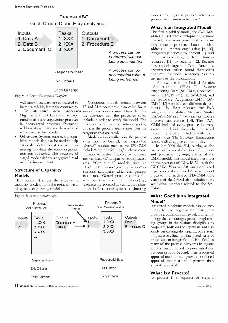
8/8/2019 CROSSTAKL 2002 CMMI feb02
http://slidepdf.com/reader/full/crosstakl-2002-cmmi-feb02 16/32
Software Engineering Technology
16 CROSSTALK The Journal of Defense Software Engineering February 2002
well-known standard are considered tobe more reliable, less risky contractors.
• To structure new processes.Organizations that have not yet cap-tured their basic engineering practicesin documented processes frequently will look at capability models as a list of what needs to be included.
• Other uses. Systems engineering capa-bility models also can be used to helpestablish a definition of systems engi-neering to which the entire organiza-tion can subscribe. The structure of staged models defines a suggested roadmap for improvement.
Structure of CapabilityModels This section describes the structure of capability models from the point of view of systems engineering models.2
Continuous models contain between17 and 24 process areas, also called focus
areas or key process areas. These describethe activities that the processes mustinclude in order to satisfy the model. Theprocess areas are grouped into categories,but it is the process areas rather than thecategories that are rated.
Models also describe how the processareas are performed, or capability.“Staged” models such as the SW-CMMinclude “common features,” such as “com-mitment to perform, ability to perform,and verification,” as a part of each processarea. “Continuous” models such asEIA/IS 731 contain “generic practices” asa second axis, against which each processarea is rated. Generic practices address thesame aspects as the common features (e.g.,resources, responsibility, verification, plan-ning); in fact, some systems engineering
models group generic practices into cate-gories called “common features.”
What Is an Integrated Model? The first capability model, the SW-CMMaddressed software development, or moreprecisely, the management of softwaredevelopment projects. Later modelsaddressed systems engineering [9, 10]integrated product development [7], and
other aspects ranging from humanresources [11] to security [12]. Becausethese models targeted different functionsorganizations often found themselvesusing multiple models separately in differ-ent areas of the organization.
An example is the Federal Aviation Administration (FAA). The SystemEngineering CMM (SE-CMM, a predeces-sor of EIA/IS 731), the SW-CMM, andthe Software Acquisition-CMM (SA-CMM) [13] were in use in different depart-ments. The FAA released the FAA
Integrated Capability Maturity Model(FAA-iCMM)3 in 1997 to unify its processimprovement efforts [14]. The FAA-iCMM included every practice in everysource model, as is shown by the detailedtraceability tables included with eachprocess area. The Software EngineeringInstitute (SEI) approved this model.
In late 2000 the SEI, serving as thecustodian for a collaboration of industryand government groups, published theCMMI model. This model integrates mostof the practices of EIA/IS 731 with theSW-CMM Version 2.0 (an unreleasedexpansion of the released Version 1.1) andmuch of the unreleased IPD-CMM. One version of the CMMI also includes someacquisition practices related to the SA-CMM.
What Good Is an Integrated
Model?Integrated capability models can do twothings for the organization. First, theyprovide a common framework and termi-nology that encourages process engineer-ing groups in the various disciplines to
cooperate, both on the appraisals and alsoideally on creating the organization’s suiteof processes. Such an integrated suite ofprocesses can be significantly beneficial, asmany of the process problems in organi-zations can be traced to poor interfacesbetween groups. Second, their associatedappraisal methods can provide combinedappraisals that cost less to perform thanseparate appraisals
What Is a Process? A process is a sequence of steps t
Inputs
1.
2.
Tasks
1. XXX
2. XXX3. XXX
...
Outputs
Document A
Data B
Responsibilities:
Exit Criteria:
Entry Criteria:
Process 1Goal: Create A&B...
Inputs
1.
2.
Tasks
1. XXX
2. XXX3. XXX
...
Outputs
Data C
Procedure D
Responsibilities:
Exit Criteria:
Entry Criteria:
Process 2Goal: Create C and D...
From Another
Process
Figure 2: Process Relationships
Inputs
1. Data A
2. Data B
3. Document C
Tasks
1. XXX
2. XXX
3. XXX
...
Outputs
1. Document D
2. Procedure E
Responsibilities:
Exit Criteria:
Entry Criteria:
Process ABC
Goal: Create D and E by analyzing ...
A process can be
performed without being documented
A process can be
documented without
being performed
Figure 1: Process Description Template
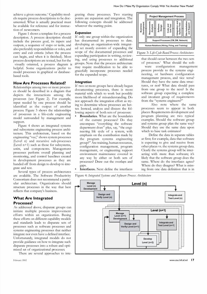
8/8/2019 CROSSTAKL 2002 CMMI feb02
http://slidepdf.com/reader/full/crosstakl-2002-cmmi-feb02 17/32
How Do I Make My Organization Comply With Yet Another New Model?
February 2002 www.stsc.hill.af.mil 17
achieve a given outcome.4 Capability mod-els require process descriptions to be doc-umented. What is actually practiced mustbe available for reference and for instruc-tion of newcomers.
Figure 1 shows a template for a processdescription. A process description shouldinclude the process goal, its inputs andoutputs, a sequence of steps or tasks, andalso preferably responsibilities or roles, andentry and exit criteria (when the processcan begin, and when it is finished). Mostprocess descriptions are textual, but for the visually oriented, a process diagram ishelpful. Some organizations prefer tomodel processes in graphical or database-based tools.
How Are Processes Related?Relationships among two or more process-es should be described in a diagram thatdepicts the interactions among theprocesses (see Figure 2). For example,
input needed by one process should beidentified as the output of anotherprocess. Figure 3 shows the relationshipsof processes in a life-cycle engineering model surrounded by management andsupport.
Figure 4 shows an integrated systemsand subsystems engineering process archi-tecture. This architecture, based on theengineering “vee,” shows system processes(Level n) and recursive sub-processes(Level n+1) such as those for subsystems,units, and components. Managementprocesses perform overall planning andmonitoring, and control baselines createdin development processes as they arehanded off from design to develop to inte-grate and test.
Several types of process architecturesare available. The Software Productivity Consortium does not recommend a partic-ular architecture. Organizations shouldstructure processes in the way that bestreflects that company’s business.
What Are Integrated
Processes? As addressed above, disparate groups caninitiate multiple process improvementefforts within an organization. Basing these efforts on different capability modelsand standards leads to disparate sets of processes such as software processes andsystems engineering processes that neitherintegrate nor even have a defined interface.Unfortunately, integrated models do notprovide guidance on how to integrate suchdisparate processes into a robust and opti-mized set of organizational processes.
There are several approaches to inte-
grating these processes. Two starting points are expansion and integration. Thefollowing concepts should be addressed whatever the starting point.
ExpansionIf only one group within the organizationhas documented its processes to date,developing an organization-wide integrat-ed set mostly consists of expanding the
scope of the documented processes andexpanding participation in writing, review-ing, and using processes to additionalgroups. Note that the process architecturemay require modification to be able togracefully incorporate processes neededfor the expanded scope.
IntegrationIf two or more groups have already begundocumenting processes, there is morematerial with which to work but possibly more likelihood of misunderstanding. Donot approach the integration effort as try-ing to determine whose processes are bet-ter. Instead, analyze and discuss the fol-lowing aspects of both sets of processes:• Boundaries. What are the boundaries
of the current processes? Do they encompass “everything the softwaredepartment does” plus, say, “the engi-neering life cycle of a system, withemphasis on the contribution made by the program systems engineering group?” Are training, human resources,configuration management, programmanagement, or engineering support
environment maintenance covered inany way by either or both sets of processes? Draw out the overlaps andgaps.
• Interfaces. Next define the interfaces
that should occur between the two setsof processes.5 What should the soft ware configuration managemeprocess provide to the systems engi-neering, or hardware configurationmanagement process, and vice versa?Should they have the same data struc-tures, or not? What data should passfrom one group to the next? Is thesoftware group expecting a completeand invariant group of requirementsfrom the “systems engineers?”
Also note where the samprocesses seem to appear in bothplaces: Requirements development andprogram planning are two typicalexamples. Should the software groupand systems group plan the same way?Should they use the same data upon which to base task estimates?
Define the data in separate tablesat first; for example, data that softwareis expecting to give and receive fromother places vs. the systems group dataClearly the systems group will be inter-
acting with more than software; it’slikely that the software group does thesame. Where do the interfaces agree? Where do they disagree? What is miss-ing from one data definition that is in
B u s i n e s s
D e v e l o p m e n t
Project Management Process
Support Processes (CM, DM, Network)
R e q u i r e m e n t s
A n a l y s i s
S o f t w a r e
D e s i g n
C o d e a n d
U n i t T e s t
I n t e g r a t i o n a n d
S y s t e m T
e s t
S i t e I n s t a l l a t i o n
Human Relations (Hiring, Firing, and Training)
B u s i n e s s
D e v e l o p m e n t
Project Management Process
Support Processes (CM, DM, Network)
R e q u i r e m e n t s
A n a l y s i s
S o f t w a r e
D e s i g n
C o d e a n d
U n i t T e s t
I n t e g r a t i o n a n d
S y s t e m T e s t
S i t e I n s t a l l a t i o n
a n d S u p p o r t
Human Relations (Hiring, Firing, and Training)
Figure 3: Life-Cycle-Based Process Architecture
Level (n+1)
Level (n)Manage
Level (n)
Development
Design and
Verify Level (n)Integrate and
Test Level (n)
Manage
Level (n+1)
Development
Design and
Verify Level (n+1)
Integrate and
Test Level (n+1)
Develop
Level (n+2)
Level (n+1)
Level (n)Manage
Level (n)
Development
Design and
Verify Level (n)Integrate and
Test Level (n)
ManageLevel (n+1)
Development
Design and
Verify Level (n+1)
Integrate and
Test Level (n+1)
Develop
Level (n+2)
Figure 4: Integrated Systems and Software Process Architecture

8/8/2019 CROSSTAKL 2002 CMMI feb02
http://slidepdf.com/reader/full/crosstakl-2002-cmmi-feb02 18/32
Software Engineering Technology
18 CROSSTALK The Journal of Defense Software Engineering February 2002
the other? It may be necessary to createjoint tiger teams to resolve conflicts – better to resolve them early in theprocesses.
• Participation. Is the systems engi-neering group expecting software par-ticipation in determining what require-ments should be allocated to software?Do (or should) systems engineersrefrain from giving any requirements
to software developers until therequirements are complete and stable?How does a systems change ripplethrough the systems and subsystem(e.g., software) processes? Work outthese and similar issues in joint processmeetings.
Integration Artifacts The artifacts that will arise from the inte-gration effort may include the following: A) Processes that did not change or have
minor adaptations:• Software processes that will remain
strictly software processes as they were before, e.g., code walk-throughs.
• Software processes that remain soft- ware processes but have to changetheir interfaces to match with sys-tems, e.g., software requirementsanalysis.
• Systems processes that remain the way they were, e.g. factory acceptancetests.
• Systems processes that remain sys-tems processes but have to changetheir interfaces to map with software
and other processes, e.g., SystemCritical Design Review.• Processes that don’t exist yet in a
documented form, but that’s accept-able for now (other processes should
acknowledge them and describe theassumed interface), e.g., programbudgeting process.
B) Processes substantially reorganized toimprove the effectiveness of the orga-nization’s set of standard processes:• Systems processes that are no longer
strictly systems processes; now merged with software or other sub-system area processes (or into other
processes such as program manage-ment or configuration managementprocesses), e.g., integration planning.
• Software processes no longer withinthe software group; now merged intosystems or other processes, e.g., inte-gration test processes or risk manage-ment processes.
• Processes that have to change to inte-grate better across the interface (per-haps delete one and use the other),e.g., requirements management.
C) New needed processes:
• Processes that need to be writtennow to address pressing organiza-tional problems, e.g., a process forterminating a program, or for provid-ing an engineering support environ-ment
Adding Compliance to a New
ModelIt is time to look at how capability modelsand processes relate in order to determinehow to add compliance to a new capabili-ty model. This requires understanding the
whole picture and a fairly good under-standing of three things:1. The organization’s processes.2. The models with which the processes
are currently compliant, and how the
organization’s processes relate tothem. (Think of the models as therequirements, and the processes as theorganization’s solution. What is thetraceability between the requirementsand the solution?)
3. The model with which you wish tocomply. (Think of this as another setof requirements with which your solu-tion is already partly compliant.)
The goal is to understand where youexisting processes do or do not comply with the new model. If you have documented traceability (“mappings”) betweenthe previous models and your processesand between the new and previous mod-els, you can infer mappings between yourprocesses and the new model.
The bad news is that mapping is a lotof work for even one new model, andthere are a lot of models out there.
The good news is that many modelask you for the same things such as “planyour work and work your plan,” [15] so what you are doing is likely to transfe without much elaboration into compliance with a new model.
Consider the heritage of the newmodel. Especially if it is based on themodels you have been using, the changesyou will have to make in your organiza-tion’s processes may be minimal.
Mapping When mapping to a single model, you arefirst setting up your processes to comply with a model; you need to know where in
your processes you perform the practicesthat the model requires. A good mappingis two-way, meaning you could either lookat an activity in a process and see whatmodel practices this activity fulfills, or youcould look at a practice in a model and see where these are included as activities inthe organization’s processes.
Once you have such a mapping, youshould then continue mapping yourprocesses to other models or standards ofinterest. Consortium members haveaccess to a tool called Quagmap6 that ispre-loaded with paragraph titles of popu-lar models and shows how they map toeach other. This allows input and mappingof an organizational set of processes toany of the preloaded models. Once a prac-tice in one of your processes is mapped toa section of one model, the tool will giveyou an “inferred mapping” of the para-graphs in another model that also maymap to this part of the process.
Figure 5 shows some of the manykinds of mappings, including mappingbetween the organizational standardprocesses and project processes. This kind
SWSE
PM
Gap Identification Reports
...
Mapping
FW 1 to
FW 2
Mapping
FW1 to
PDP 1
Projectês
Defined
Process
(PDP1)
Frameworks (FW)
...QA
...
Tailoring
...
Organizational
Standard
Process (OSP)
SW-CMM
SE-CMM
ISO 9001 Mapping
FW1 to
OSPCMMI
FAA-iCMM
SWSE
PM
Compliance Reports,
...
Mapping
FW 1 to
FW 2
Mapping
FW1 to
PDP 1
Project's
Defined
Process
(PDP1)
Frameworks (FW)
...QA
...
Tailoring
...
Organizational
Standard
Process (OSP)
SW-CMM
SE-CMM
ISO 9001
Others
Mapping
FW1 to
OSPCMMI
FAA-iCMM
Figure 5: Mapping Among Models and Processes

8/8/2019 CROSSTAKL 2002 CMMI feb02
http://slidepdf.com/reader/full/crosstakl-2002-cmmi-feb02 19/32
How Do I Make My Organization Comply With Yet Another New Model?
February 2002 www.stsc.hill.af.mil 19
of mapping, a record of project tailoring,is required for Level 3 in capability mod-els.
When mapping processes to processareas, none of the capability modelsrequires the processes of the organizationto match the process areas of the modelone for one. A process may combine thepractices of two different process areassuch as configuration management and
data management, or planning and track-ing. Several processes may be written tosatisfy one process area (most organiza-tions find a need to write more than onetest process, perhaps unit test, integrationtest, and system test).
Gaps A mapping between models should be ableto highlight practices in the new modelthat were not well covered in the previousmodel. Concentrate on these gaps andaddress them on a case-by-case basis. Hereare several ways to handle gaps:• If your processes already include a
practice because your business needsthe practice, you may have covered thegap already.
• If your business truly does not need anew practice, you may be able to tailorout a requirement. For example, a sys-tem integrator may be able to omitpractices related to implementing thedesign of a component.
• If the new model specifies additionalpractices that you do not currently per-form but should, an activity might have
to be added to (or changed in) one of your existing processes. An examplemight be certain measurement or risk management activities.
• If the old model did not include oneaspect of your business that really doesapply and should be improved, and thenew one does, you might decide to write a new process to address thisaspect (for example, appraisal of cus-tomer satisfaction).
You certainly do not, and should not, cre-ate a whole new set of processes to meetthis new model.
It Sounds Like so Much WorkIt is not as hard as it seems. The biggestdifficulty in complying with a processimprovement model is in making peopleunderstand what processes are, getting them written down, and getting manage-ment to enforce disciplined use of theseprocesses. Specific activities that may beunique to a particular model are much lessimportant than getting the organization tobehave in a disciplined manner. Whetherinitial processes are configuration man-
agement processes, trade studies analysisprocesses, or even processes for running efficient meetings, it is easier to transferdiscipline to additional processes than toperform processes in a disciplined mannerin the first place.
Similarly, once organizationally stan-dardized processes are understood, andprograms know how their own processesdiffer from the standard processes, new
programs begin to realize substantial sav-ings in startup time and cost because thebasic processes are already in place, andtraining is also easier. Adding new prac-tices to the set of standard organizationalprocesses, or even adding a few new processes, is easier than establishing anorganization-wide process infrastructure inthe first place.7
Moving From a SystemsEngineering Model to an
Integrated Model The above suggestions address mappingsin general. This section looks at specificchanges an organization might need tomake when the current model is a systemsengineering model and the new model isan integrated capability model.
Maturity Rating If you are used to continuous models andchoosing process areas to emphasize, notethat both the CMMI and the FAA-iCMMalso include the concept of an officialorganizational rating, or maturity level,
comparable to a rating in a staged model. An official Maturity Level 2 rating willrequire the achievement of the model’sspecified Level 2 process areas (andMaturity Level 3 requires both Level 2 andLevel 3 process areas). Check to see if these are areas where you have put atten-tion to date, and if you are seeking a rat-ing, work hardest on any gaps.
MeasurementMeasurement and the use of measure-ment data are called out much moreexplicitly in both integrated models than
in the systems engineering models, andmuch earlier in CMMI (Level 2). This may be a surprise, but it is a good change. Work hard to comply with the measure-ment requirements and you will berewarded with a much smoother processimprovement effort afterward.
Process Improvement InfrastructureOrganizational process focus is muchmore clearly spelled out in the CMMI thanin the systems engineering models.Systems engineering groups generally real-
ize that they need a process infrastructurebut this process area, originally from theSW-CMM, helps define clearly what isneeded.
Skills and Knowledge The integrated models include procesareas on training or organizational training These may have a smaller scope than theManage Competency focus area of
EIA/IS 731, but may be more explicit in what must be done to comply. Review thepractices against those of your processesthat are mapped to manage competency.
More Good NewsIf you have reached mostly Level 2s orLevel 3s in a systems engineering modelyou will find you have most of theCMMI’s requirements for comparable lev-els covered. This is much easier than start-ing over.Some Questions to Ask
This section suggests some additionaareas to investigate when adopting a newmodel.
Who does “systems engineering?”Do not assume the model considers “sys-tems engineering” to be a particular orga-nizational group. Most models do notspecify who performs the systems engi-neering activities, just that they need to bedone.
Do not make the mistake of assumingyour “systems engineers” have to doeverything, including configuration man-agement, training, or program planning
and tracking. While your systems engi-neers will need to be involved in theseprocesses (managing the configuration ofitems they work on; requesting, takingand possibly even planning training; andproviding estimates and measurementdata to program managers), manyprocesses are run by groups other thanthose called “systems engineers.” Further-more, most subsystem areas, includingsoftware development, also have to per-form systems engineering activities suchas trade studies among potential architec-
tures and validation against user need. Besure they do not think they are exemptbecause the systems engineers do that.
How specific is the model? ISO9000-2000 is fairly general, requiring cer-tain aspects of processes to be well docu-mented but not specifying much of theircontent (e.g., what is feasibility analysis)Some models such as EIA/IS 731 statethat analyses must be done “as appropri-ate” while others, such as military stan-dards and guidebooks, may explicitly spec-ify a “feasibility analysis” deliverable and

8/8/2019 CROSSTAKL 2002 CMMI feb02
http://slidepdf.com/reader/full/crosstakl-2002-cmmi-feb02 20/32
Software Engineering Technology
20 CROSSTALK The Journal of Defense Software Engineering February 2002
include a required data item description.How specific should your processes
be? The temptation is to documentprocesses by specifying all items in greatdetail so that any auditor can see the doc-umentation is complete. This is not a goodidea because (a) it will be more difficult toget engineers to follow 500 pages of doc-uments than 50, (b) 500 pages is moreexpensive to write, (c) 500 pages is more
expensive to maintain, and (d) some mod-els, such as ISO 9000-2000, are strict aboutfollowing that which is documented. Thisemphasizes that you should not buildrigidity into a documented process if thebusiness needs it to be flexible.8
Finally, most processes that have beenin place for some time probably eithermeet most business needs, or else every-one knows they are broken. Look first atthose places where your processes are bro-ken. You may find that the model calls outperformance of some practices that youdo not do, and should. You can use themodel as leverage.
ConclusionsComplying with a new capability model ismuch easier than starting fresh if theorganization already complies with anoth-er model, particularly when the new model is an evolution of the old model.Especially if an organization’s processesdescribe essential business practices andare mapped to the old model rather thanstrictly based on it, it is fairly straightfor- ward to use other mappings to infer what
parts of the processes may be lacking,according to the new model. Use yourstandard process improvement process toincorporate changes to meet the require-ments in the new model. Other than yourprocess group, the rest of the organizationonly has to understand the processes they are already using and the few changes;they do not have to understand the new model at all.◆
References1. ISO 9000 International Standards for
Quality Management. InternationalOrganization for Standardization,Switzerland, 1994 and 2000.
2. Sheard, Sarah A. “The FrameworksQuagmire.” CrossTalk, Sept. 1997<www.stsc.hill.af.mil>.
3. Sheard, Sarah A., “The FrameworksQuagmire, A Brief Look.” Proceedingsof INCOSE. 1997b.
4. Sheard, Sarah A., and J. Lake, eds.“Systems Engineering Standards andModels Compared.” Proceedings of INCOSE. 1998.
5. Paulk, Mark, B. Curtis, M. Chrissis, and
C. Weber, eds. Capability Maturity Model for Software, Version 1.1.Software Engineering Institute,Carnegie Mellon University, 1993.
6. Systems Engineering Capability ModelEIA/IS 731. Electronics Industries Affiliates, 1999.
7. An Integrated Product DevelopmentCapability Maturity Model, Version0.9. Software Engineering Institute
and Enterprise Process ImprovementCollaboration, Carnegie MellonUniversity, 28 Oct. 1996.
8. Capability Maturity Model Integration,Software-Systems-IPPD-Acquisition, Version 1.02b. Software Engineering Institute, Carnegie Mellon University,2000.
9. Bate, Roger, et al. Systems Engineering Capability Maturity Model, Version1.1. Software Engineering Institute,Carnegie Mellon University, 1995.
10. Systems Engineering Capability Assessment Model, Version 1.5.International Council on SystemsEngineering (INCOSE), 1995.
11. Curtis, Bill, William E. Hefley, and Sally Miller, eds. People Capability Maturity Model. Software Engineering Institute,CMU/SEI-95-MM-02, Sept. 1995.
12. Hefner, R., et al. Systems Security Engineering Capability Maturity Model. International Systems Security Engineering Association, 1999.
13. Software Acquisition Capability Maturity Model. Version 1.01.Software Engineering Institute,
Carnegie Mellon University, 1997.14. Ibrahim, Linda, et al. The Federal
Aviation Administration IntegratedCapability Maturity Mode, Version 1.0.Federal Aviation Administration, Nov.1997.
15. Ferguson, JoAn, and Sarah A. Sheard,eds. “Leveraging the CMM for ISO/IEC 12207 Compliance.” Nuts andBolts, IEEE Software, Sept./Oct. 1998.
Notes1. This paper originally appeared in the
Proceedings of the Eleventh AnnualInternational Symposium of theInternational Council on SystemsEngineering, Melbourne, Australia, July 2001.
2. Other models place more emphasison practices (parts of process areas)and goals (groupings of practices).
3. The FAA also released an appraisalmethod that includes an internal andan external “full appraisal” as well asseveral reduced-cost appraisal ver-sions. This method is called the FAA-iCMM Appraisal Method or FAM.
4. This is a fairly narrow definition ofprocess, chosen for understandabilityOther broader definitions can bemore abstract.
5. For process robustness, involve asmany process users as possible in anyrestructuring of processes.
6. Quagmap is a trademark of theSoftware Productivity Consortium.
7. In fact, the most mature organizations
have the easiest time of all. Theessence of Level 5 is continuousimprovement. At this level, insertingnew or better processes is just thenormal way of doing business.
8. A classic case of a process that needsto be flexible is how to develop adesign that meets requirements. Someengineers think linearly and can doStep 1, Step 2, Step 3, but the bestengineers often develop a picture intheir head and cannot follow a step- wise procedure. Your processshould specify outputs and requiredtasks to produce the outputs, butshould leave open how to do the tasksparticularly those that can be done bya single person, whenever possible.
About the Author
Sarah A. Sheard has 20years experience in sys-tems engineering, onsystems from satellitesto air traffic control.
Currently at theSoftware Productivity Consortium,Sheard helps companies begin systemsengineering process improvementefforts and integrate the software andsystems engineering aspects of bothdevelopment work and processimprovement efforts. Sheard is current-ly the chair of International Council onSystems Engineering‘s (INCOSE’s)Measurement Technical Committee andin the past has served INCOSE as chair
of the Communications Committee andas programs chair of the WashingtonMetropolitan Area Chapter. Sheardreceived a bachelor’s degree in chemistry from the University of Rochester and amaster’s degree in chemistry from theCalifornia Institute of Technology.
2214 Rock Hill Rd.
Herndon,VA 20170-4227
Phone: (703) 742-7106
E-mail: [email protected]

8/8/2019 CROSSTAKL 2002 CMMI feb02
http://slidepdf.com/reader/full/crosstakl-2002-cmmi-feb02 21/32February 2002 www.stsc.hill.af.mil 21
To better understand the relationshipbetween the Capability Maturity
Model® IntegrationSM (CMMISM ) andFunction Point Analysis (FPA), it is nec-essary to review the CMMI project.Readers already familiar with the CMMIcan skip forward to the next section,“What are Function Points?”
The CMMI project began in 1998 as acollaborative effort of industry, govern-
ment, and the Software Engineering Institute (SEI) to merge various SEImodels [1]:• Software Capability Maturity Model®
(SW-CMM).• Systems Engineering Capability
Maturity Model (SE-CMM) (SystemsEngineering published by EnterpriseProcess Improvement Collaboration:EPIC).
• The Systems Engineering Capability Appraisal Model (SECAM)(Published by International Council
on Systems Engineering: INCOSE).• Systems Engineering Capability Model (SECM) is the collaborativemodel of the SE-CMM and SECAM(EIA/IS-731).In December 2000, a public review of
CMMI V1.02 Models (consisting of CMMI-SE/SW/Integrated Product andProcess Development [IPPD] V1.02 andCMMI-SE/SW V1.02) was announcedand is currently under review. For moreinformation on the SEI’s CMMI modeland the previous models, refer to<www.sei.cmu.edu/cmmi>.
Today’s CMMI Model The current CMMI is similar to its pred-ecessor models in a number of ways.For example, the CMMI V1.02Integration Systems/Software Engineer-ing model has retained the five maturity levels of the SW-CMM and a set of cor-responding process areas (formerly known as key process areas or KPAs) inthe SW-CMM.
Level 1: Initial/Performed Organizations appraised at Level 1 arecharacterized as simply “performing”software processes and do so in a mannerthat is often ad hoc or chaotic. The com-petence and heroics of the individualsdoing the work drive how the activitiesare performed at this level. This first levelin the CMMI model is the most commonfor development organizations embark-
ing on process improvement initiatives.Processes defined at Level 1 are funda-mental to software development.
Level 2: Managed (Formerly calledRepeatable in the SW-CMM) A Level 2organization is more rigorous in bothhow it performs software processes andin the processes it performs.
At level 2, processes are managed: That is, they are planned, performed,monitored, and controlled for individualprojects and groups, or they are stand-
alone processes to achieve a given pur-pose. At level 2, managing the processachieves both the specific goals for theprocess area, as well as meets other goalssuch as cost, schedule, and quality.
Level 3: Defined A Level 3 organization actually defines itsprocesses and tailors them based on theorganization’s set of standard processes.Deviations beyond those allowed by thetailoring guidelines are documented, jus-tified, reviewed, and approved.
Level 4: Quantitatively Managed(Formerly called Managed in the SW-CMM) At Level 4, processes are con-trolled using statistical and other quanti-tative techniques. Quantitative objectivesfor product quality, service quality, andprocess performance are established andused as criteria in managing processesProduct quality, service quality, and
process performance are understood instatistical terms and are managedthroughout the life of processes.
Level 5: Optimizing At Level 5, processes are continuallimproved based on an understanding ofthe common causes of variation inherentin processes. The CMMI SE/SW modelidentifies a consolidated set of processareas across the five levels. These will bediscussed in further detail in the sectionsthat follow.
What are Function Points?Function points (FP) are a technicallyindependent measure that quantifies thesize of functional user requirements ofsoftware. The function point countingmethod used to calculate the number offunction points is known as theInternational Function Point UsersGroup (IFPUG) function point method[2]. In its Counting Practices Manualrelease 4.1, IFPUG identifies the follow-ing objectives for function point count-ing:
• To measure the functionality the userrequests and receives.
• To measure independently of imple-mentation technology.
• To provide a normalization factor forsoftware measurement.Companies adopt function point size
measurement in place of the traditionaphysical source lines of code because FPare independent of technology andimplementation. For readers unfamiliar with FP, we commonly refer to them asthe square feet of software because FP
How Function Points Supportthe Capability Maturity Model Integration ©
Carol Dekkers and Barbara Emmons Quality Plus Technologies, Inc
This article demonstrates the mutual effect of increased process maturity and an organization’s maturity in their use of Function Point Analysis (FPA). As a company moves to a higher maturity level according to the Capability Maturity
Model ®
Integration SM
(CMMI SM
), its measurement maturity should also increase. The tie between the CMMI’s process areas and FPA is not well understood, yet there is a direct connection that can be made between the model and FPA. The purpose
of this article is to illustrate what those links are in terms understandable to non-experts in software measurement.
“ Function points
are a technically
independent measure
that quantifies the size
of functional user
requirements of software.”
© Copyright 2001 Barbara Emmons and Carol Dekkers,
Quality Plus Technologies, Inc. All rights reserved.

8/8/2019 CROSSTAKL 2002 CMMI feb02
http://slidepdf.com/reader/full/crosstakl-2002-cmmi-feb02 22/3222 CROSSTALK The Journal of Defense Software Engineering February 2002
quantify the size of the logical user1
requirements. This is similar to quantify-ing a building’s size by adding up thesquare feet from its floor plan.
IFPUG provides the following stan-dard definitions in their FP Counting Practices Manual release 4.1 (1999):
“Function point (FP). A measure, which represents the functional size
of application software.”
“Function point analysis. A standardmethod for measuring softwaredevelopment and maintenance fromthe customer’s point of view.”
For further information about functionpoints, refer to the IFPUG Web site<www.ifpug.org>, or see “Managing (theSize of) Your Projects” by Carol Dekkersin Feb. 1999 CrossTalk.
What Is the Link? The question remains “Where is the link between measurements, the CMMI’sprocess maturity, and FP?” The SEI’sCMMI SE/SW Model 1.02 presents astandard set of software processes to besatisfied before an organization can beappraised at a particular capability matu-rity level. Measurement, if used appro-priately, can be a facilitator that canenable companies to move ahead andcomplete many of these process areas.
Measurement should encourageprocess repeatability: It is exactly the
place where process maturity and FPcoalesce to bring productive and positivebottom line results. The FPA counting process mirrors structured peer review tosolidify “and” quantify the functionaluser requirements. As such, there areprocesses in the CMMI that could besupported by the process of document-ing the logical functions counted withFPs, while other areas can be supportedby the FP measure itself. In the lattercase, the numbers and ratios based onthe FP measure can be the most signifi-cant factor in achieving the process area.(See “Applying Function Point Analysisto Requirements Completeness” by Carol Dekkers and Mauricio Aguiar inFeb. 2001 CrossTalk. )
While a picture can paint a thousand words, examples also provide illumina-tion better than words. For example, inCMMI Level 2: Managed, the following Level 2 process areas (PAs) could besupported through FP based measure-ment:1. Requirements Management PA:• Measurements can be made to assess
the status of requirements – are they reviewed or accepted or rejected?
• The amount of change activity can becaptured – compare and quantify theFP size of change requests.
2. Project Planning PA:• Estimates for size of software work
products (using FP) or changes mustbe derived according to documentedprocedure.
In another example, the CMMI Level3 PAs include a formal software measure-ment program. In addition, repeatableprocesses can be supported with FP-basedmeasurement. Traditionally, the capability maturity models did not explicitly mentionmeasurement until Level 3: It wasassumed to be a common theme underly-ing the process areas of every level. InMarch 2001, Dr. David Zubrow of theSEI revealed that the latest CMMI modelnow includes an explicit process area atLevel 2 for measurement and analysis.
In 1998, Ken Dymond stated in hisarticle Using and Implementing the CMM ,“Many Level 1 companies fail to reachLevel 2 … Lack of measurement to aidproject planning, tracking and oversight,and requirements management. One of the most often missed measures is that of the size of various tasks/products to beperformed/produced.”
For the past three years, authors andleading experts have recognized theimportance of software sizing in theCMM models. FP “size” addresses andquantifies software size objectively from alogical (user) point of view, independentof implementation, and is a valid sizing measure to use in conjunction with theCMMI.
FP Maturity Model As an organization evolves to higherCMMI levels, its usage of FP-based meas-urements generally also evolves. This doesnot refer to the evolution of the functionpoint methodology per se, but rather tohow the organization leverages their FPcounting process and makes use of their
FP data and resultant measurements. As briefly described in the previous
section, FP can be used in almost allprocess areas of the CMMI, either as apart of a FP-based measurement, or theFPA process itself can be used to enhancethe process area.
Goal-Question-Metric
Measurement ApproachIt is important to determine what FP-based measurements are appropriate forthe current level (and capability) of your
organization, as well as goals. As a case in-point, trying to implement Level 4 typesof software measurement based on FPmay be impossible, or at least frustratingto do in an organization appraised asLevel 1.
A good method for determining whatmeasurements make sense for your organ-ization at its current maturity is the Goal-Question-Metric (GQM)-approach. GQM
provides that the goals of your organiza-tion and your measurement program beoutlined first, before determining whichquestions need to be answered (to meetthe goals), and which measures willanswer the questions.
This is similar to determining require-ments before building software – GQMsets up the requirements (goals) firstbefore setting the measurement details(the questions and metrics). Briefly, with-out getting into the depths of GQM, it issufficient to say that goals must beSMART:
S - StrategicM - Measurable A - AchievableR - Realistic T - Targeted
(Note-These may be different than otheruses of the SMART acronym.)
Ensuring that you have SMART goalsbefore you decide on the questions andmetrics to reach those goals will assist youto align your measurements with your ownorganizational capability (realistic, achiev-able).
FP-Based Measures for CMMI This section illustrates what measurements and measurement processes can beused effectively at each level of theCMMI. If the FP process supports theprocess area, a “+” is indicatedOtherwise, it is the FP measure that sup-ports the process area.
CMMI Level 1 – Initial/Performed A maturity Level 1 is typically ad hoc andchaotic. For example, sample systemmeasurements for Level 1 are “size ofapplications in FP.” Sample software proj-ect measurements for Level 1 are “size ofprojects in FP.”
CMMI Level 2 – Managed These Level 2 PA support the inclusion ofFP-based measurement:• Requirements Management – Use FP
to quantify the size of the functionarequirements.
• Project Planning – Use FP to estimateeffort and cost.
• Project Monitoring and Control – Use
Software Engineering Technology

8/8/2019 CROSSTAKL 2002 CMMI feb02
http://slidepdf.com/reader/full/crosstakl-2002-cmmi-feb02 23/32
How Function Points Support the Capability Maturity Model Integration
February 2002 www.stsc.hill.af.mil 23
FP to keep track of scope changes,percent complete, etc.
• Supplier Agreement Management – Use FP to define size of requirements(application/project being outsourced)and for monitoring supplier’s progress,evaluating alternatives for outsourcing,and writing service level agreements.
• Measurement and Analysis – Collecting FP data, reporting data to man-
agers/project managers, and under-standing how FP can/cannot be used.
• Process and Product Quality Assurance – Use FP to track defects.
• Configuration Management – Use FPto track changes to requirements andto measure impact to project size. These are sample system measure-
ments for Level 2:• Portfolio Size and Growth Trends –
Percent increase/change of FPs fromone date to another.
• Age of Applications – Percent of appli-cations or percent of FPs older thanfive years, etc.
• Application Support Rates for Individual Applications – Number of FP perresource.
• FP by Language, Platform – Percent of FP Mainframe Cobol, etc.
• Application Churning – Number of change requests and FP size. These are sample software project
measurements for Level 2:• Delivery Rates/Duration Delivery Rates
– FP/hour or FP/month.• Productivity – Hours per FP.
• Stability Ratio, Scope Creep/Requirements Volatility – Percent FPadded, changed, deleted.
• Project Cost per FP – Dollars per FP.• Defect Ratio – Defects per FP.• Testing Proficiency Ratios – Percent
defects found pre-delivery/totaldefects (up to one month post-deliv-ery) per FP.
CMMI Level 3 – Defined These Level 3 PAs support the inclusionof FP-based measurement:• Requirements Development – FP
analysis process serves as a design walk-through of requirements.
• Technical Solution – Review FPA fordesign issues and for documenting interfaces and project documentation.
• Product Integration – Use FP to meas-ure interface with other applications.
• Verification – Update FPs based on verification process.
• Validation – Track defect data and useFP as denominator.
• Organizational Process Focus+ – Include FPA as a standard organiza-
tional process.• Organizational Process Definition+ –
Include FP as part of the organiza-tional measurement repository.
• Organizational Training – n/a.• Integrated Project Management – n/a.• Risk Management+ – Using FP to
measure the size of the application willenable assessing risk changes when thesize changes.
• Decision Analysis and Resolution+ – Using FP to assist in decision-making,i.e., impact of scope changes onschedule, extend schedule, increaseresources, renegotiate scope, etc. These are sample system measure-
ments for Level 3:• Application Support Rates for
Organization – FPs per month.• Support Activity Trends – Number of
FPs per person over time.• Application Maintenance Load per
Person – FPs per person.
• Application Maintenance Cost per FP – Dollars per FP.• Mean Time to Repair – Using FP to
normalize based on application size. These are sample project measure-
ments for Level 3 (compare projects):• Delivery Rates by Type of Project
(development, enhancement, mainte-nance, language, platform, etc.) – Hours per FP.
• Duration Delivery Rates by Type of Project (elapsed duration) – FPs permonth or hours per FP.
• Trending of Delivery Rates – FPs permonth or hours per FP over time.
• Testing Proficiency Ratios forOrganization – Percent defects foundpre-delivery/total defects (up to 1month post-delivery) per FP.
• Scope Creep/Requirements Volatility – Comparisons between projects, per-cent of change measured with FPs.
• Defect Density – Defects per FP.
CMMI Level 4 – Quantitatively
Managed These Level 4 PAs support the inclusion
of FP-based measurement:• Organizational Process Performance –
Use FP as one of the measures forestablishing performance baselines forprocesses.
• Quantitative Project Management – Use FP as the common denominatorfor selecting measures and statisticalcontrol of products and quality. These are sample system measure-
ments for Level 4:• Enterprise Productivity Rates – Total
FP/ total information systems work
effort.• Enterprise Quality Rates – Defects per
FP compiled for the enterprise.• Enterprise Cost Per FP – Dollars per
FP compiled for the enterprise.• Mean Time to Failure – Elapsed
time/number of failures, normalizedby FP.
• Mean Time to Repair – Elapsedtime/number of failures, normalized
by FP. These are sample software projec
measurements for Level 4:• Enterprise Project Delivery Rates –
Hours per FP compiled for all proj-ects.
• Enterprise Quality Rates – Defects perFP compiled for all projects.
• Enterprise Cost Per FP – Dollars perFP compiled for all projects.
• Statistical Process Control of ProjectDelivery Rates Trend Analysis ofProjects – Using FP to normalize.
CMMI Level 5 – Optimized These Level 5 PAs support the inclusionof FP-based measurement:• Causal Analysis and Resolution –
Analyzing defect data using FP as thecommon denominator enables com-parisons between projects; allowsevaluating impact of changes by usingFP as the common denominator.
• Organizational Innovation andDeployment – Use FP as a measurefor establishing process improvementobjectives.
These are sample system measurements for Level 5 (all normalized by FP):• Repair Cost Ratio.• Defect Density – Defects/FP.• Cumulative Defects.• Defect Distribution by Severity.• Defects by Cause.• Mean Time Between Defects.• Application Support Rate Trends
After Process Improvements. These are sample software projec
measurements for Level 5 (all normalizedby FP):• Defect Detection Ratio (by phase
found). Also known as inspectioneffectiveness.
• Defect Removal Efficiency.• Defect Distribution by Severity.• Defects by Cause.• Delivery Rate Trends After Process
Improvements.• Statistical Process Control of Defect
Data.• Cost of Defect Removal by Inspection
Phase.• SPC of Process Information.• Post Release Defect Stability (by
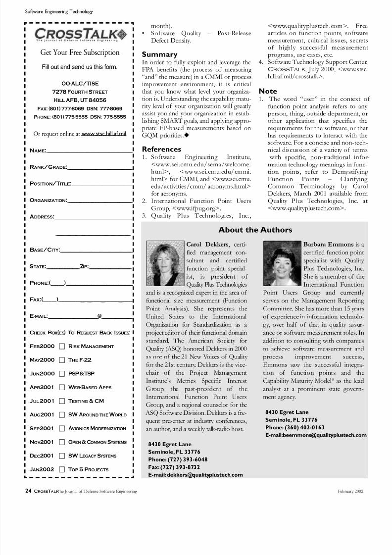
8/8/2019 CROSSTAKL 2002 CMMI feb02
http://slidepdf.com/reader/full/crosstakl-2002-cmmi-feb02 24/3224 CROSSTALK The Journal of Defense Software Engineering February 2002
month).• Software Quality – Post-Release
Defect Density.
SummaryIn order to fully exploit and leverage theFPA benefits (the process of measuring “and” the measure) in a CMMI or processimprovement environment, it is criticalthat you know what level your organiza-
tion is. Understanding the capability matu-rity level of your organization will greatly assist you and your organization in estab-lishing SMART goals, and applying appro-priate FP-based measurements based onGQM priorities.◆
References1. Software Engineering Institute,
<www.sei.cmu.edu/sema/welcome.html>, <www.sei.cmu.edu/cmmi.html> for CMMI, and <www.sei.cmu.edu/activities/cmm/ acronyms.html>
for acronyms.2. International Function Point Users
Group, <www.ifpug.org>.3. Quality Plus Technologies, Inc.,
<www.qualityplustech.com>. Freearticles on function points, softwaremeasurement, cultural issues, secretsof highly successful measuremenprograms, use cases, etc.
4. Software Technology Support CenterCrossTalk, July 2000, <www.stschill.af.mil/crosstalk>.
Note1. The word “user” in the context o
function point analysis refers to anyperson, thing, outside department, orother application that specifies therequirements for the software, or thathas requirements to interact with thesoftware. For a concise and non-tech-nical discussion of a variety of terms with specific, non-traditional information technology meanings in func-tion points, refer to DemystifyingFunction Points – ClarifyingCommon Terminology by Carol
Dekkers, March 2001 available fromQuality Plus Technologies, Inc. at<www.qualityplustech.com>.
Software Engineering Technology
Get Your Free Subscription
Fill out and send us this form.
OO-ALC/TISE
7278 Fourth Street
Hill AFB, UT 84056
Fax: (801) 777-8069 DSN: 777-8069
Phone: (801) 775-5555 DSN: 775-5555
Or request online at www.stsc.hill.af.mil
NAME:________________________________________________________________________
RANK/GRADE:_____________________________________________________
POSITION/TITLE:__________________________________________________
ORGANIZATION:_____________________________________________________
ADDRESS:________________________________________________________________
________________________________________________________________
BASE/CITY :____________________________________________________________
STATE:___________________________ZIP:___________________________________
PHONE:(_____)_______________________________________________________
FAX:(_____)_____________________________________________________________
E-MAIL:_________________________________________@_________________________
CHECK BOX(ES) TO REQUEST BACK ISSUES:
FEB2000 RISK MANAGEMENT
MAY 2000 THE F-22
JUN2000 PSP & TSP
APR2001 W EB-BASED APPS
JUL2001 TESTING & CM
AUG2001 SW AROUND THE W ORLD
SEP2001 A VIONICS MODERNIZATION
NOV2001 OPEN & COMMON S YSTEMS
DEC2001 SW LEGACY S YSTEMS
JAN2002 TOP 5 PROJECTS
About the Authors
Carol Dekkers, certi-fied management con-sultant and certifiedfunction point special-ist, is president of Quality Plus Technologies
and is a recognized expert in the area of functional size measurement (FunctionPoint Analysis). She represents theUnited States to the InternationalOrganization for Standardization as aproject editor of their functional domainstandard. The American Society forQuality (ASQ) honored Dekkers in 2000as one of the 21 New Voices of Quality for the 21st century. Dekkers is the vice-chair of the Project ManagementInstitute’s Metrics Specific Interest
Group, the past-president of theInternational Function Point UsersGroup, and a regional counselor for the ASQ Software Division. Dekkers is a fre-quent presenter at industry conferences,an author, and a weekly talk-radio host.
8430 Egret Lane
Seminole, FL 33776
Phone: (727) 393-6048
Fax: (727) 393-8732
E-mail:[email protected]
Barbara Emmons is acertified function pointspecialist with Quality Plus Technologies, Inc.She is a member of theInternational Function
Point Users Group and currently serves on the Management Reporting Committee. She has more than 15 yearsof experience in information technolo-gy, over half of that in quality assur-ance or software measurement roles. Inaddition to consulting with companiesto achieve software measurement andprocess improvement success,Emmons saw the successful integra-tion of function points and theCapability Maturity Model® as the lead
analyst at a prominent state govern-ment agency.
8430 Egret Lane
Seminole, FL 33776
Phone: (360) 402-0163
E-mail:[email protected]

8/8/2019 CROSSTAKL 2002 CMMI feb02
http://slidepdf.com/reader/full/crosstakl-2002-cmmi-feb02 25/32
Field Report
February 2002 www.stsc.hill.af.mil 25
Battlefield information has alwaysbeen an important component of
war fighting. However, the U.S. Army’s vision of the future is a fighting force
linked as an integrated collection of interoperable systems. Loosely referredto as digitization, the addition of soft- ware-based information systems to weapon systems is the means to achievethis goal. Graphical maps populated with icons representing enemy andfriendly forces are coupled with obsta-cles such as mine fields and air defenseartillery to provide what is called situa-tional awareness (SA) data. Satellites, air-craft, ground vehicles, and individualtroops collect this data. It is distributed
via a wireless computer network know asthe Tactical Internet (TI). The data isused for mission planning and execu-tion, and greatly enhances the effective-ness of every individual system, and the Army as a whole.
One of the key digitization chal-lenges centers on the definition andimplementation of a standard messageprotocol. Historically, different familiesof weapon systems have preferred dif-ferent protocols, selecting them basedon the needs and limitations of theirindividual systems. Since there was no
requirement, or even any mechanism forthem to interoperate, there was no rea-son for them to share common proto-cols. To obtain the desired interoperabil-ity, a standard message protocol for useby all nodes on the TI was needed.
Toward this end, a digital messageprotocol known as the Joint VariableMessage Format (JVMF) has beenselected for use by the Army. In fact, allDepartment of Defense (DoD) systemsand our allied forces will eventually implement the protocol. The joint desig-
nation means that the protocol will bemulti-service. It is the variable formatnature of the protocol that adds a largeamount of complexity and difficulty for
the software developers who are faced with its implementation.
A variable format was selected inpart to minimize input/output (I/O)loading on the very limited transmissionbandwidth that is available with current Army wireless technology. Standard Army radios have been improved totransmit voice and data, but have a nom-inal throughput of about 9600 bits persecond. This capacity is a significant bot-tleneck in the transmission of graphics
and messages that can reach into thehundreds of megabytes in size.
Message Specifications The specification for the JVMF messageprotocol is the Technical InstructionDesign Plan that is maintained by the Army’s Communication and ElectronicsCommand (CECOM). The specificationis effectively maintained as a databasethat is known as the Variable MessageFormat (VMF) Integrated Database(VID). The VID defines the possible
data fields and their associated parame-ters, structure, and the message casesand conditions. Cases and conditions areassertions about the consistency of the
fields in the messages, and the parsermust implement them in order toencode and decode a valid message.
CECOM produces a new databaserelease when either new messages havebeen added, or existing ones have beenchanged. The specification of the mes-sages is nested up to six levels deep, andeach level can have potentially thousandsof data elements that may or may not bepresent. The current version of the VIDhas 121 messages, with millions of fieldspossibly present. The information that
could be contained in the full messageset if all fields were populated wouldcause the storage size for the messagesto be in the terabytes range.
By design, JVMF protocol eliminatesthe need to transmit empty, placeholderdata packets that would be required in afixed-format, character-based protocol This means that only message fields thathave valid user data – as signified by a bitknown as the field presence indicator –get transmitted. This reduces the trans-mission load on the hardware. Howeverthe complexity of the variable format
places very stringent requirements onthe message parsers that encode the userdata into properly formatted binary dataand then subsequently decode the binarydata back into user data on the receivingend. If one bit is set incorrectly, theentire message is unreadable by therecipient. Also, as the specification ofthe message types and field definitions isexpected to continually evolve, someearly studies have deemed the protocolunworkable based on the assertion thatthe message parsers would be too com-
U.S.Army Develops High Quality,Extremely Low Cost Digital Message Parser
Edgar DalrympleU.S. Army Aviation and Missile Command
This article describes a software project managed by the U.S. Army Aviation and Missile Command, Software Engineering
Directorate (SED). The project was nominated to CrossTalk in its search for the top five software projects in the U.S. government. The project received high scores by the Software Technology Support Center review team for its description of the
development of a highly automated process that the SED established to produce a digital message parser for the U.S. Army.
The parser developed by the SED team, and their support contractor Science Applications International Corporation, has helped major weapon systems to demonstrate interoperability deemed critical to the future of the U.S. Army. The SED
process has produced software of extremely high quality, and at the same time, extremely low cost. This article describes how
these two characteristics, which may often seem mutually exclusive, were designed into the product by virtue of the development
process that was established by the SED.
“ The specification of
the messages is nested
up to six levels deep, and
each level can have
potentially thousands of
data elements that may or may not be present.”

8/8/2019 CROSSTAKL 2002 CMMI feb02
http://slidepdf.com/reader/full/crosstakl-2002-cmmi-feb02 26/32
Field Report
26 CROSSTALK The Journal of Defense Software Engineering February 2002
plex to build, test, and maintain.
First to Face Digitization The parser project was initially estab-lished in support of the Bradley A3Fighting Vehicle, managed by the U.S. Army Tank and Automotive Command(TACOM). The A3 was one of the firstmajor Army systems faced with digitiza-tion. While working with TACOM and
its prime contractor, United DefenseLimited Partnership, the SoftwareEngineering Directorate (SED) antici-pated and solved the problems associat-ed with the development of the parsersby using sophisticated software engi-neering methodologies commonly usedin compiler development.
The methodology for the develop-ment of the JVMF message parser wasdesigned to solve the following prob-lems:• Produce software of exceptionally
high qual ity.• Maintain very short cycle times for
product release. The means by which these character-
istics were achieved included the follow-ing:• Maximum use of automation.• Use of a Software Engineer ing
Institute Capability Maturity Model®
Level 3, and later Level 4, process. The basic approach to the solution
involved the following steps:• Describe each of the messages in the
VID in a formal Backus-Naur Form
(BNF) grammar. This allowed for anunambiguous specification of themessage structure.
• Develop automated software tools toread the VID and directly producethe BNF grammar.
• Develop automated software tools toread the BNF grammar and producethe Ada source code for the messageencoder and decoder, i.e., the parser.
• Develop a test case generator to readthe database and produce the suiteof test cases to fully test all messagefields for valid data, data ranges, andcases and conditions checks. The SED defined a two-level BNF
grammar. This allowed the entire (i.e.semantic and syntactic) behavior of theparser to be formally described. Thefact that a two-level grammar wasdefined was essential to producing aparser that was capable of performing the cases and conditions checking. Notdoing this would have made implement-ing the checking a manual activity.Development and maintenance of thecode verifying cases and conditions by
manual means would have made achiev-ing the quality and cycle time goalsunobtainable. Failing to implement thecases and conditions checking at all would have produced an unacceptably inferior product.
To support the quality and automa-tion goals, the team defined and devel-oped software tools wherever possibleto automate every feasible step of the
process. This ensured a highly repeat-able process was put in place. Once thetools were mature and debugged, itproved to be a process capable of pro-ducing extremely high levels of quality.
A brief summary of some of thetools and their functions follows. Thesetools are primarily written in the Adaprogramming language.• Data Extraction Tool: Extracts the
message specification data from thedatabase supplied by CECOM tocreate text files used by other tools.
• Grammar Generator Tool: Reads thetext files produced by the dataextraction tool and produces theBNF grammar to represent the mes-sages.
• Parser Generator: Reads the gram-mar generated by the grammar gen-erator and produces the Ada sourcecode files that represent the messageparser for the messages.
• Test Data Generator: Generatesmore than 6,000 test cases to test theparser.New tools are added as the cus-
tomers’ needs demand. For instance, aSymbol Table interface to the parser wascreated for the Program ExecutiveOffice of the Aviation ElectronicsCommand. The symbol table parser wasimplemented in the Improved DataModem (IDM). This was done to isolatesoftware changes to the IDM, thusavoiding frequent changes to interfacing components in the avionics systems of helicopters. The flight certification con-cerns and associated costs due tochanges to avionics software make this a very important benefit to IDM cus-tomers.
Product PerformanceCurrently the IDM is used in three heli-copters. The ability to use the sameparser software in three systems hassaved an estimated $1.2 to $1.5 milliondollars versus the cost of redeveloping similar code for each system. If used onan additional fourth aircraft as planned,an additional $2 million dollars in sav-ings is projected. There is also anunquantified cost savings due to the
quality of the product. Attempting tointegrate unreliable, low quality softwareinto an embedded, real-time system canhave disastrous consequences on cost,schedule, and product quality. The usersof this product have come to trust theSED development process to supporttheir cost and schedule with some of thehighest quality code in the Army.
The following metrics reflect th
performance that has been achieved bythe project. The Ada source code for theparser as counted by the terminal semi-colon method consists of approximately204 thousand lines of code. The dura-tion required to fully generate, test, doc-ument, and deliver this code is threemonths from the receipt of a valid data-base. Engineering releases can be donein two to three days. The effort requiredis four person months, based on 152person hours/person month. The postrelease defect density of the last threereleases, as measured for six monthsafter the commencement of operationause is 0.1 defects per 1,000 single line ofcode (SLOC). The current cost of thedelivered product, ignoring the costs ofthe initial development of the tool-setis approximately $0.04 per SLOC.
The product is delivered with a fulset of documentation, including require-ments documents, test plan and proce-dures, application program interfacespecification, interface control docu-ment, version description document Ada source code, and C language bind
ings. Users can compile and link onlythe encoder and decoder files that areneeded by their application, thus avoid-ing the overhead of a solution that con-sists of a standard executable. The Clanguage bindings enable the product tobe used on virtually every hardware plat-form used by the Army.
As a final measure of product quality, the product is tested using theCECOM supplied VMF Test Tool(VTT). The VTT is the official test toolthat provides certification of correcimplementation of the message proto-col. The IDM was independently testedby the CECOM labs and found to be infull compliance with the message stan-dard.
Conclusion This project provides a key technologyto support one of the most significantorganizational goals in the Army, inter-operability via digitization. Theincreased SA data provides for a majorincrease in the effectiveness of Armysystems. The highly automated develop-

8/8/2019 CROSSTAKL 2002 CMMI feb02
http://slidepdf.com/reader/full/crosstakl-2002-cmmi-feb02 27/32
U.S.Army Develops High Quality, Extremely Low Cost Digital Message Parse
February 2002 www.stsc.hill.af.mil 27
ment process allows for extremely shortcycle times in the generation and releaseof the product. This allows weapon sys-tems to quickly update their ability tointeroperate and provides the war fight-ing advantages of increased SA.
This would not be possible withoutthe process the team has put in place tosupport this product. The methodology employed on this project was sophisti-cated and targeted to the risk associated with the application. It is a textbook example of how to craft a solution to aproblem based on risk. The productspeaks for itself. Hardly a week goes by that some other project fails to call andrequest a copy of the parser.
The fact that the technology is gov-ernment owned allows for it to be dis-tributed free of charge to DoD pro-grams. The relatively small cost of maintaining this product is borne by theSED to the benefit of the entire Army.
Custom enhancements, such as thesymbol table interface, are funded by customers, notably IDM product office.
This project is an outstanding exam-ple of how the Army Life CycleSoftware Engineering Centers can beused to benefit a wide range of Army systems in a cost effective and high
quality manner.
Key Players The most important part of any projectis its members. The author would like tospecifically mention the following teammembers who have been key to thisprogram:• James Magnusson, Science Applica-
tions International Corporation
(SAIC) assembled the technicalteam.
• Doris Chan, SAIC, has served as theparser technical lead for six years.
• John Shannon, SAIC, developed anddefined the methodology to employ the formal BNF grammar.
All of these people have more than 20years experience in the design, develop-ment, and management of embeddedsoftware systems for military applica-tions:• Larry Stanbery, SAIC, enhanced the
automation of the testing processand has more than 10 years of soft- ware experience.
• Charles Hyder, SAIC, provided soft- ware quality assurance support.
• Debra Henry, EER Systems, provid-ed configuration management sup-port.◆
About the Author
Edgar Dalrymple isa lead project engi-neer and divisionmanager at the U.S. Army’s Aviation andMissile Command,
Software Engineering Directorate.For 15 years, he has supported major Army systems in the areas of soft- ware quality assurance, independent verification and validation, and soft- ware project management. In addi-tion to the Joint Variable MessageFormat message parser, he currently supports the Bradley A3 moderniza-tion. He received a bachelor’s degreein nuclear engineering from NorthCarolina State University in 1979.
U.S.Army Avionicsand Missile Command
AMSAM-RD-BA-SQ
Redstone Arsenal,AL 35898
Phone: (256) 842-0187
E-mail: edgar.dalrymple@
sed.redstone.army.mil
WEB SITES
Note: Newcomers to software process improvement or the Capability Maturity Model ® IntegrationSM will benefit from these Web sites that
offer information and training on all aspects of software process improvement.
Software Technology Support Center www.stsc.hill.af.milThe Software Technology Support Center (STSC) is an AirForce organization established to help other U.S. governmentorganizations identify, evaluate, and adopt technologies toimprove the quality of their software products, efficiency inproducing them, and their ability to accurately predict thecost and schedule of their delivery. The STSC is offering a free
workshop to U.S. government employees on Capability
Maturity Model Integration Version 1.1 on May 21-23,2002.
Software Technology Conference www.stc-online.orgThe Software Technology Conference (STC) is theDepartment of Defense’s premier software conference. Onetutorial and one track will be specifically aimed at addressingthe Capability Maturity Model Integration Version 1.1. TheCMMI tutorial can be found on Monday, April 29, 2002Track 4 at 1:00 p.m.; the CMMI track can be found on
Wednesday, May 1, 2002 Track 4 at 1:00 p.m.
Software Engineering Institute www.sei.cmu.edu
The Software Engineering Institute (SEI) is a federally fundedresearch and development center sponsored by theDepartment of Defense to provide leadership in advancing thestate of the practice of software engineering to improve thequality of systems that depend on software. SEI helps organi-zations and individuals to improve their software engineeringmanagement practices. The site features complete informationon models it is currently involved in developing, expanding, ormaintaining, including the Capability Maturity ModelIntegration, Capability Maturity Model for Software, Software
Acquisition Capability Maturity Model, Systems EngineeringCapability Maturity Model, and more.
Software Productivity Consortium www.software.orgThe Software Productivity Consortium (SPC) is a nonprofitpartnership of industry, government, and academia. The SPCdevelops processes, methods, tools, and supporting servicesto help members and affiliates build high-quality, compo-nent-based systems, and continuously advance their systemsand software engineering maturity pursuant to the guidelinesof all of the major process and quality frameworks.Membership is open to all U.S. or Canadian-based compa-nies, government agencies, and academic organizations.
8/8/2019 CROSSTAKL 2002 CMMI feb02
http://slidepdf.com/reader/full/crosstakl-2002-cmmi-feb02 28/3228 CROSSTALK The Journal of Defense Software Engineering February 2002
About STC
The best way to describe STC 2002 is that it is jam-packed! This
year's conference will include more than 180 events to choose from,
including general sessions, luncheons, plenary sessions, and
presentation tracks. If you work with software, STC provides
outstanding training and networking opportunities. Some
organizations report that they must send a small army to absorb allthe information that is important to their organizations.
In its fourteenth year, STC is the premier software technology
conference in the Department of Defense and is co-sponsored by the
United States Army, United States Marine Corps, United States Navy,
United States Air Force, the Defense Information Systems Agency
(DISA), and Utah State University Extension. We anticipate over
3,000 participants this year from the military services, government
agencies, defense contractors, industry, and academia.
General Sessions, Panel Discussion, and Plenary Speaker s
The STC Opening General Session will be held Monday morning of
conference week and will feature two keynote speakers:
Congressman James V. Hansen, Republican, 1st District of Utah,
and Mr. Lloyd K. Mosemann, II, Senior Vice President for
Corporate Development, SAIC. The co-sponsors will host a panel
discussion Tuesday morning, moderated by Ms. Dawn C.
Meyerriecks, Chief Technology Officer for the Defense Information
Systems Agency.
Wednesday's plenary session speaker is Mr. Kevin Fitzgerald,
Senior Vice President and General Manager, Oracle Corporation.
Thursday, Mr. Grady Booch, Chief Scientist, Rational Software
Corporation, will address the conference. STC will be capped off
Thursday afternoon with Mr. Tom Talleur, Managing Director of
Forensic and Litigation Services for KPMG LLP, as the Closing
General Session keynote speaker.
Special Sessions
Sponsored track presentations will be offered throughout the week by
the following organizations: CinC Interoperability Program Office
(CIPO), Computer Resources Support Improvement Program
(CRSIP), Defense Information Systems Agency (DISA), Earned
Value (EV), Institute of Electrical and Electronics Engineers (IEEE),
International Council on Systems Engineering (INCOSE), JointStrike Fighter (JSF), Office of the Secretary of Defense (OSD),
Software Engineering Institute (SEI), and Software Technology
Support Center (STSC).
STC is Endorsed by:
Lt Gen John L. Woodward, DCS/Communications and
Information, U.S. Air Force
Lt Gen Harry D. Raduege, Jr., Director, Defense Information
Systems Agency
LTG Peter M. Cuviello, Director of Information Systems for
Command, Control, Communications, and Computers, U.S.Army
RADM Kenneth D. Slaght, Commander, Space and Naval Warfare
Systems Command, U.S. Navy
Dr. Donald C. Daniel, Deputy Assistant Secretary for Science,
Technology, and Engineering, U.S. Air Force
Mrs. Debra M. Filippi, Deputy Director of Command, Control,
Communications, and Computers, U.S. Marine Corps
THE FOURTEENTH ANNUAL
Software Technology ConferenceForging the Future of Defense Through Technology
29 APRIL - 2 MAY 2002 • SALT LAKE CITY, UT
There is great wisdom in relying on the technology that produces the strength of a "drop-forged" tool. Just as hammering metal makes it
stronger, our defense systems will be made stronger through the application of technology. Technology can be seen as the hammer we will
use to shape the future of defense. The Software Technology Conference (STC) will focus on how we can best use technology to strengthen
the future. This year's conference is shaping up to be the best yet. Join us in sharing your knowledge, opinions, research, and lessons learned
and help us in "Forging the Future of Defense Through Technology."
•Alternative Methods to Software
Development
•Business: Evolution
•Capability Maturity Models
•Common and Open Systems
Architectures
•Data Management
•E-ducation
•Earned Value
•Enterprise Software
•Higher Levels of Process Maturity
•High Integrity Software
•Information Assurance
•Interoperability
•Lessons Learned
•Process Improvement
•Project Management
•Quality/Quality Assurance
•Requirements
•Software Architectures
•Software Engineering Best Practices
•Software Intensive Weapon Systems
•Tools
•XML
•Wireless
On the Agenda
•Test

8/8/2019 CROSSTAKL 2002 CMMI feb02
http://slidepdf.com/reader/full/crosstakl-2002-cmmi-feb02 29/32February 2002 www.stsc.hill.af.mil 29
Special Events
STC 2002 features many networking opportunities such as the Opening
Welcome Reception on Monday, and the Drag 'n Drop Social and Hotel
California "A Salute to the Eagles" musical entertainment onWednesday. Space for these events is limited.
Traveling with a companion? We are excited to offer two optional tours
at this year’s conference: an afternoon walking tour of the newly
completed Gateway Center and an evening dinner tour at Gardner
Village, both on Tuesday. You may purchase tickets to both of these
optional tours as well as a companion package which includes
admittance to selected conference events.
Registration
Completed registration form and payment must be received by
25 March 2002 to take advantage of the early registration fees. Credit
cards will not be charged until 1 April 2002. The conference fee
structure for STC 2002 is as follows: Discounted registration fee (paid by 25 March 2002):
Active Duty Military/Government* $595
Business/Industry/Other $725
Regular registration fee (paid after 25 March 2002):
Active Duty Military/Government* $665
Business/Industry/Other $795
* Military rank (active duty) or government GS rating or
equivalent is required to qualify for these rates.
The Housing Bureau of the Salt Lake Convention and Visitors Bureau
(SLCVB), using the online Passkey system, handles housing
reservations. Housing has been available since May 2001; therefore,
some government rate guestrooms at specific hotels may not be
available. To access the Passkey system, log on to the STC Web site
at www.stc-online.org and select the Housing Reservation button. If you prefer to make your reservation using a traditional method, a PDF
version of the housing form is available online.
Delta Airlines Special Discounted Airfare
Delta Airlines is our official host airline for all STC 2002
attendees. Take advantage of the five percent discount off Delta’s published
round-trip fares within the continental U.S. Aten percent discount is offered on
Delta’s domestic system for travel to STC 2002 based on the published
unrestricted round-trip coach (Y06) rates. Book your flight by calling Delta
Meeting Network® Reservations at 1-800-241-6760, Monday-Sunday
8:00 a.m. – 11:00 p.m. Eastern Time, or have your travel agent call for you. You
must refer to File Number 181932A when making your reservations.
Trade Show
STC 2002 will again feature its accompanying trade show, providing
180+ exhibitors the opportunity to showcase the latest in software and
systems technology, products, and services. This year's schedule hasbeen adjusted to allow participants more time to interact with the
vendors without conflicting with conference presentations.
Exhibit space is sold in increments of 10' x 10' at a rate of $1575 per
10' x 10' space if application is received on or before 15 February
2002. Should space still be available after this date, booth space shall
be processed at the rental rate of $1775 per 10' x 10' space. Special
fees and restrictions may apply to certain types of booth space.
Complete trade show rules, regulations, and updated hall layout are
available on the STC Web site.
All badged exhibit personnel wishing to attend the entire conference
are eligible for a discounted conference registration fee. Please utilize
the conference registration form that was mailed to the exhibit
manager in early January to register for the conference.
Ada Core Technologies, Inc.AFIT Software Professional
Development ProgramAuburn UniversityBattelleBEA Systems, Inc.Boeing Co.DDC-I, Inc.Defense Contract
Management AgencyDISAFranklin Covey Government
Products GroupGalorath, Inc.GTSI Corp.Hewlett-Packard Co.Hill AFBIBM/Lotus/TivoliIntegrated System
Diagnostics, Inc.
Jacada, Inc.JAWS S3 2002JOVIAL Program OfficeLockheed MartinMCTSSAMERANTMicrosoft Corp.NASA GSFC SEWPNorthrop Grumman
Information TechnologyNovellObjective Interface
Systems, Inc.OO-ALC/TISPHI Enterprises, Inc.pragma Systems Corp.Praxis Critical Systems, Ltd.Quality Plus TechnologiesQuantitative Software
Management, Inc.
Quest SoftwareRational SoftwareReal-Time Innovations, Inc.RS Information
Systems, Inc.SAICSAS Institute, Inc.Scitor Corp.SEEBEYOND
SilverStream Software, Inc.Software ConfigurationSolutions, Inc.
Software Dimensions &International Institute forSoftware Testing
Software EngineeringInstitute
Software ProductivityConsortium
SPAWAR
STSCSun Microsystems, Inc.SYNERGEN, Inc.Top Graph'XUnited DefenseUnited States Air ForceUSACECOM SECUtah State University
Extension
ViON Corp.Vitech Corp.Wind River
STC 2002 Exhibiting Organizations (As of 11/16/01)
General Information
Trade Show Inquiries
435.797.0047
Technical Content Inquiries
Media Relations
435.797.1349
www.stc-online.orgSource Code: CT6A

8/8/2019 CROSSTAKL 2002 CMMI feb02
http://slidepdf.com/reader/full/crosstakl-2002-cmmi-feb02 30/3230 CROSSTALK The Journal of Defense Software Engineering February 2002
Departments
LETTERS TO THE EDITOR
Having read the November 2001 issue of CrossTalk,I am somewhat at a loss concerning the section “Dynamic
vs. Static Invocation” in the article Factors to Consider When Selecting CORBA Implementations by Dr. Thomas J. Croak.
The author must have misunderstood the meaning of staticinvocation or he is using the term in a (for me) unknown
way. The author states that “static invocation can be used if
the language, compiler, and operating system (and hard- ware) are known to be the same on both client and server.” This statement is of course true, but certainly static invoca-tion can be used regardless of differences in client and serv-er operating systems, compilers, and languages.
Also in the section “Questions for the CORBA ORBSalesman,” it is stated that “..., and you run the risk of future software failures given an operating system upgradeon portions of the architecture [when using static invoca-tion].” I fail to see how this can be true, given that theCORBA architecture is specifically designed to be platform-and language-independent. Clients do not have to know,and indeed cannot know, implementation details of a serv-er on the basis of the interface definition, and so will not beaffected by server-side implementation changes.
According to my textbooks and to the best of my knowledge:
• Static invocation is used when you compile a client stubfrom Interface Definition Language and use that to con-tact the server skeleton. It is also known as early or com-pile-time binding. In other words, the interface (but notthe implementation) is known beforehand.
• Dynamic invocation is used when the client does not
know the interface in advance but queries the ORB foran interface (or method) definition. The client thenbuilds a request based on the obtained definition andinvokes it. This is known as late or run-time binding.
The difference between static invocation and dynamicinvocation is very analogous to the difference betweendirectly calling into vtable method pointers or using IDispatch.Invoke (after having called IDispatch.GetIdsOfNames and IDispatch.GetTypeInfo and so on ...)in COM.
Either way, the client will always be insulated from theserver implementation details.
According to the glossary of the CORBA 2.5 specifica-tion (September 2001):• Static invocation: Constructing a request at compile
time. Calling an operation via a stub procedure.• Dynamic invocation: Constructing and issuing a request
whose signature is possibly not known until run-time.Best Regards,
The term “invocation” is overloaded to mean both thedetermination of the interface representation and the actu-al method call. The reader is using the first meaning of theterm while I was using the second, and specifically stated so.
The interface representation can be determined at compiletime (referred to in the CORBA specification as StaticInvocation Interface) or at run-time (referred to asDynamic Invocation Interface in the CORBA specifica-tion). The method call on an object can be “invoked”dynamically or statically. In this sense of the term, theCORBA specification as well as other texts are not particu-larly clear. The interpretation I was using is that a dynami-cally invoked method call implies that the data will be mar-shaled, and a statically invoked method call implies that thedata will not be marshaled. A danger of such ambiguity isthat it leaves certain points open to the interpretation of theobject request broker (ORB) provider, who may not imple-ment the ORB consistently with the specification's inten-
tion. The standpoint of my article dealt with safety-critical
embedded and command-and-control systems typical of those found in Department of Defense combat systems
where a function must be deterministic. Dynamic invoca-tion, in either sense of the term would never be consideredto be deterministic. Static invocation can be deterministicsubject to the actual construction of the operating system,the compilers, and the ORB itself. However, the static invo-cation can become non-deterministic should any of thesechange. When I said, “Static invocation can be used if the
language, compiler and operating system (and hardware) areknown to be the same on both client and server,” I shouldhave said, “Static invocation can be used safely if …”
Speaking from experience, I can attest that the CORBA
architectural philosophy of platform and language inde-pendence has not been faithfully extended to all ORBimplementations, for all platforms and all languages. If youhave an environment of mixed operating systems and lan-guages, it is often difficult to find a single ORB vendor forthe whole environment. If you must use multiple vendors’products, you will rarely have interoperability problems
with the standard data types such as integer, real, or string. Try passing a scalar array or a covariance matrix and there will often be interoperability problems. When I said, “Yourun the risk of future software failure given an operating system upgrade on portions of the architecture,” I waspointing out that an ORB supplier might make design deci-sions based on specific operating system functionality. If
the underlying functionality of the operating systemchanges, the ORB’s behavior may also change. When anORB is ported to a different operating system or operating system version, testing does not always uncover all thebehavior nuances, which may ultimately affect performance.
I feel strongly that any architect or designer should care-fully consider the implications of any design decision onthe expected behavior of the system as a whole, as well asthe potential for unexpected changes in behavior given typ-ical system evolution in compilers, operating systems, andcommercial off-the-shelf products.
Dear CrossTalk Editors:
Dear CrossTalk Editors:
— Tom J. Croak
— Jan Holst Jensen

8/8/2019 CROSSTAKL 2002 CMMI feb02
http://slidepdf.com/reader/full/crosstakl-2002-cmmi-feb02 31/32
BACKTALK
February 2002 www.stsc.hill.af.mil 31
W hen was the last good fight in the software industry? BillGates versus the government – Boring. Napster was
over before it started. Capability Maturity Model® (CMM® ) versus, …well no CMM? We haven’t had a good intellectualmêlée since Ada Wars.
Still, the air is thick with anticipation – an old fashion donny-brook is on its way.
With the help of Elton John and the words of Bernie Taupin,slightly customized, let’s explore the skirmish (It helps if you sing the Italic sections).
It's getting late have you seen my mates Ma tell me when the boys get here It's seven o'clock and I want to rock
Want to get a belly full of beer 1
In government’s corner the Process Champion – weighing inon everything – Capability Maturity Model® IntegrationSM
(CMMISM ).
Captain Fantastic raised and regimented, hardly a hero Just someone his mother might know
Very clearly a case for process and models “Two teas both with sugar please 2
Backed by the top-down management approach of theSoftware Engineering Institute.
But the biggest kick I ever got Was doing a thing called the CMM Rock
While the other kids were Coding round the clock
We were hopping and bopping to the CMM Rock
Well CMM Rocking is something shocking When your level just can't keep still
I never knew me a better time and I guess I never will Oh Lawdy mama those Friday nights When SEPG wore her process tight
And the CMM Rocking was out of sight 3
In the People’s corner – the Technology Champion weighing very little – Agile Software Development (ASD).
You know you can't hold me forever I didn't sign up with you
I'm not a process for your friend’s appraisal This boy's too young to be singing the blues 4
Backed by a grass-roots manifesto of simplicity, communica-tion, and courage.
So goodbye maturity road Where the dogs of piety howl
You can't plant me in your model I'm going back to my code
Back to the howling old owl in the woods Writing the thorny back code
Oh I've finally decided my future lies Beyond the maturity road 4
You don’t believe it? Check out “CTO Diaries” in the January
issue of Software Development Magazine , Jack Ganssle’s article inthe December issue of Embedded Systems Programming , or theNovember/December issue of IEEE Software .
Don't give us none of your aggravation We had it with your discipline
Saturday night's alright for fighting Get a little action in 1
In the November/December issue of IEEE Software , MarkPaulk claims that eXtreme Programming can work well withthe CMM.
Too late to save myself from falling I took a chance and changed your way of life But you misread my meaning when I met you
Closed the door and left me blinded by the light
Don't let the sun go down on me Although I search myself, it's always someone else I see
I'd just allow a fragment of your life to wander free But losing every process is like the sun going down on me 5
Maybe Mark has something? After all, CMM is all about man-aging software processes. eXtreme Programming and its agilecousins are focused on developing software. Why couldn’t you
use agile software development and still be a CMMI Level 5? Actually, you could tan leather and be a CMMI Level 5.
We've thrown in the towel too many times Out for the count and when we're down
Captain Fantastic and the Brown Dirt Cowboy From the end of the world to your town 2
Are you kidding? We can’t get along because it’s not abouprocess or technology. It’s about money. Few have the finan-cial backing to concomitantly invest in higher levels of maturi-ty and agile software development. Even if you could, who hasthe intestinal fortitude to balance the complexity of CMMI with the simplicity if ASD? What takes priority, predictabilityor agility?
The battle is coming. As with Ada, there will be no clear win-ner or loser but we will learn more about our organizations,profession, and ourselves, and we will be better for it.
The Captain and the Kid stepping in the ring From here on sonny, it's a long and lonely climb 2
— Gary Petersen, Shim Enterprise, Inc
The Captain and the Kid
1. Saturday Night’s Alright, Elton John & Bernie Taupin, © 1973 Dick James Music Limited.2. Captain Fantastic and the Brown Dirt Cowboy, Elton John & Bernie Taupin, © 1975 Big Pig Music
Limited.
3. Crocodile Rock, Elton John & Bernie Taupin, © 1972 Dick James Music Limited.4. Goodbye Yellow Brick Road,Elton John & Bernie Taupin, © 1973 Dick James Music Limited.5. Don’t Let The Sun Go Down On Me,Elton John & Bernie Taupin,© 1974 Big Pig Music Limited
8/8/2019 CROSSTAKL 2002 CMMI feb02
http://slidepdf.com/reader/full/crosstakl-2002-cmmi-feb02 32/32
CrossTalk / TISE
7278 4th Street
Bldg. 100
Hill AFB, UT 84056-5205
PRSRT STD
U.S. POSTAGE PAID
Albuquerque, NM
Permit 737
Sponsored by
Computer Reso
Support Improve
Program (CRS
The Fourteenth Annual
Software Technology Conference
Forging the Future of Defense Through Technology
29 April – 2 May 2002Salt Palace Convention Center
Salt Lake City, Utah
800•538•2663
NOW OPEN!
Conference Registration
Housing Registration
Exhibit Registration
REGISTER TODAY!
The Premier
Software Technology
Conference of the
Department of Defense
Source Code: CT6
Visit www.stc-online.org for
complete conference agenda