crossbed: an application for determining paleocurrent direction
TRANSCRIPT

CROSSBED: An Application For Determining PaleocurrentDirection from Polydeformed Cross-bedding Data
Page 1 of 18
α1
δ
α2
Figure 1: Hypothetical retrodeformation geometry requiring two stages of rotation.
Introduction
The CROSSBED application is designed to retro-deform cross-bedding data to determine thepaleocurrent direction. The application is designed for process cross-bedding from polydeformedterranes in a 2-step process:
1. Step 1 rotation: the rotation necessary to make the data station top/bottomset bed co-planar to the regional “tangent sheet layer” is calculated. The data station foreset attitudeis rotated in the same manner. If the top/bottomset bed is overturned, the absolute valueof the rotation is greater than 90 degrees. In Figure 1 the angles "1 and "2 represent twoexamples of this rotation about the regional fold hinge. Rotating the top/bottomsetbedding attitudes to be coplanar with the tangent sheet layer in effect retro-deforms thefolded layer into a single plane.
2. Step 2 rotation: the second rotation is determined by calculating the rotation needed tomove the regional tangent sheet layer attitude to the horizontal. The foreset attitude isrotated in this manner. The down-dip plunge and bearing is the paleocurrent direction. Ifa “simple” rotation is selected this step is skipped. The rotation of the tangent sheet layerto the horizontal attitude is indicated by angle * in Figure 1.
Any type of paleocurrent data, including cross-bedding, may be retro-deformed to its originalattitude as long as the primary top/bottomset bedding attitude is known at the location where the

CROSSBED: An Application For Determining PaleocurrentDirection from Polydeformed Cross-bedding Data
Page 2 of 18
Figure 2: Example of rotation path for retro-deformation.
foreset attitude is measured and recorded. Ifpaleocurrent data is measured from a terrane whereregional folds plunge significantly, the user willneed to determine the attitude of the "tangent sheetlayer" attitude. The tangent sheet layer is definedas the attitude of the plane that would contain theregional fold hinge as the true dip vector. If theregional fold hinge is determined visually orstatistically (i.e. plotting poles to top/bottomsetattitudes to define a cylindrical fold girdle) on astereographic projection, rotating the hinge point tothe east-west line of the stereonet and tracing thegreat circle that the hinge falls upon will define theregional tangent sheet layer attitude. Figure 1displays the geometry of a plunging regional foldcontaining cross-bedding in a schematic exampleof a regionally folded terrane with a plunginghinge. Note that the rotation required to make thetop/bottomset attitude coplanar with the regionaltangent sheet layer is generally unique for eachdata observation, and therefore quite tedious toprocess manually. The rotation axis for the Step 1rotation is defined by the pole to the plane thatcontains the top/bottomset pole, and the regionaltangent sheet layer pole. This rotation axis will always fall on the regional tangent layer attitudegreat circle. Figure 2 displays an example of the retro-deformation process given the followingdata:
Regional tangent layer attitude: N 30 E 64 ETop/Bottomset attitude: N 10 W 72 WForeset attitude: N 13 W 76 W
In this example the step 1 rotation is -58 degrees about the step 1 rotation axis (see Figure 2)that rotates the pole to the top/bottomset attitude (TP) to the pole to the regional tangent layer(RP). The foreset pole is rotated in the same manner moving the FP to FP’ in Figure 2. Both ofthe step 1 rotations occur about the step 1 rotation axis, that is itself the pole to the planecontaining TP and RP. The plane containing TP and RP is indicated in Figure 2 by the greatcircle passing through these two points. Because of the geometrical model used by CROSSBEDrotations viewed down-plunge of the rotation axis are positive if counterclockwise, and negativeif clockwise. Therefore, visualization of TP being rotated through less than 90 degrees to the RP
CROSSBED: An Application For Determining PaleocurrentDirection from Polydeformed Cross-bedding Data
Page 3 of 18
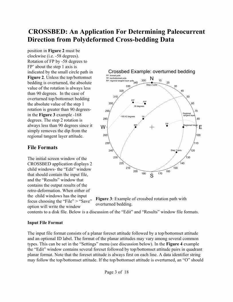
Figure 3: Example of crossbed rotation path withoverturned bedding.
position in Figure 2 must beclockwise (i.e. -58 degrees).Rotation of FP by -58 degrees toFP’ about the step 1 axis isindicated by the small circle path inFigure 2. Unless the top/bottomsetbedding is overturned, the absolutevalue of the rotation is always lessthan 90 degrees. In the case ofoverturned top/bottomset beddingthe absolute value of the step 1rotation is greater than 90 degrees-in the Figure 3 example -168degrees. The step 2 rotation isalways less than 90 degrees since itsimply removes the dip from theregional tangent layer attitude.
File Formats
The initial screen window of theCROSSBED application displays 2child windows- the “Edit” windowthat should contain the input file,and the “Results” window thatcontains the output results of theretro-deformation. When either ofthe child windows has the inputfocus choosing the “File” > “Save”option will write the windowcontents to a disk file. Below is a discussion of the “Edit” and “Results” window file formats.
Input File Format
The input file format consists of a planar foreset attitude followed by a top/bottomset attitudeand an optional ID label. The format of the planar attitudes may vary among several commontypes. This can be set in the “Settings” menu (see discussion below). In the Figure 4 examplethe “Edit” window contains several foreset followed by top/bottomset attitude pairs in quadrantplanar format. Note that the foreset attitude is always first on each line. A data identifier stringmay follow the top/bottomset attitude. If the top/bottomset attitude is overturned, an “O” should

CROSSBED: An Application For Determining PaleocurrentDirection from Polydeformed Cross-bedding Data
Page 4 of 18
Figure 4: Example input and output windows in CROSSBED.
follow the attitude (see Figure 4 edit window example).
Output File Format
The output of theapplication iscontained in the"results" childwindow (Figure 4).The contents of thiswindow may besaved as a text filethat may be used asinput for thestereographicanalysis programNETPROG. Therotated position ofthe foreset poles areincluded in theresults file. Inaddition, the rotationpath of the foresetpole may beoptionally includedas a series of user-defined annotations, as in the Figure 4 example. Figure 5 displays theCROSSBED output results in the NETPROG application main window. Note that the smallcircle paths of the 2-step rotation retro-deformation are plotted along with the retro-deformedforeset pole. The small circle step-1 paths greater than 90 degrees are produced by theoverturned top/bottomset beds (see Figure 4).
The NETPROG application (see later section on working with external applications) contains allof the options necessary to generate publication quality diagrams, including contoured equal-areaand rose diagrams. The NETPROG application can also evaluate the statistical significance oforientation trends in the data set. If the user wishes to plot the retro-deformed foreset beds as apaleocurrent rose-type diagram, the output format should be set to “Azimuth/Quadrant ForesetTrue Dip” type (see “settings” menu discussion below), and the rotation path should be de-selected. The same retro-deformed data plotted in Figure 5 is plotted in Figure 6 with thesesettings so that the paleocurrent direction is indicated in a Rose-type diagram. The statistical

CROSSBED: An Application For Determining PaleocurrentDirection from Polydeformed Cross-bedding Data
Page 5 of 18
Figure 5: Retro-deformed Heflin area foreset poles with2-step rotation paths.
least-squares vector fit is also plotted in Figure 6 indicating a mean paleoslope true dip attitudeof 5, S45E.
The CROSSBED Menu System
Configuring and data processing is accomplished through the main menu system of theCROSSBED application. Below is a description of each of the main and submenu items, andhow they are used to process data.
The File Menu
The file menu contains dialogs foropening and saving data files. Inmany cases the input data files maybe created in other applicationssuch as spreadsheets and databasemanagement systems. A separatediscussion with examples of howthis may be accomplished isdiscussed in a later section.
The “Open” Menu Item in theFile Menu
Selecting the menu choice “File” >“Open” allows the user to open anexisting data file that is formattedspecifically for CROSSBED.Activating this menu option willdisplay a standard “File Open”operating system dialog that willdisplay all files with a “.TXT”extension in the default folder(Figure 7). Selecting a text file andthen clicking on the “Open” buttonwill load the file into the “Edit”child window. The edit window is afully functional text editor,therefore, it is possible to type in allof the data manually into the editor and then save the data to a disk file. It is also possible to

CROSSBED: An Application For Determining PaleocurrentDirection from Polydeformed Cross-bedding Data
Page 6 of 18
Figure 6: Rose-type diagram of the retro-deformed Heflinpaleocurrent data.
open an existing file, and then addnew data to the editor window, andthen save all of the data to a file. Ifthe file name already exists, the userwill be prompted to verify that thefile should be over-written.
The “Save” Menu Item in the FileMenu
The “File” > “Save” option in themain menu is used to save thecontents of either the “Edit” or“Results” window to a disk file.When the “Save” option is selectedthe CROSSBED program detectswhich of the two child windows hasthe focus, and then saves thecontents of the window to a diskfile. If the file name indicatedalready exists the program will askif the user wants to overwrite theexisting file. The file used in thesave operation is added to the childwindow caption (“Edit” or“Results”) inside the squarebrackets. If the contents of the“Results” window have not beensaved the brackets will be empty. Ifa file name has already beenindicated by the user in a save operation, a subsequent save will re-use the file name. If the userindicates “yes” to overwriting the existing file, the same file will then contain the currentcontents of the active child window.
The “Save As” Menu Item in the File Menu
The “Save As” dialog activated from the “File” menu activates the same operating system dialogthat the “Save” option activates. See the above discussion of the “Save” option.
The “Exit” Menu Item in the File Menu

CROSSBED: An Application For Determining PaleocurrentDirection from Polydeformed Cross-bedding Data
Page 7 of 18
Figure 7: Dialog opened with the “File” > “Open” option.
Figure 8: The “File Save” option from the “File” menu.
The “Exit” option in the main “File”menu will exit the CROSSBEDapplication, abandoning any datacontained in the child windows.Make sure that you have saved anynewly added data before selectingthis option. You can also exit theprogram by selecting the “X” iconin the upper right corner of the mainapplication window.
The Edit Menu
The “Edit” main menu is mainlyused to copy and paste text from one window to another, or from one application to another. Thepaste operation is especially important when “pasting” data from external applications.
The “Cut” Menu Item in the Edit Menu
Selecting the CUT menu item underthe EDIT menu allows for thedeletion of selected text in thecurrently active editor window.Although the text will disappearfrom the edit window, it will becopied to the windows clipboardwhere it may be "pasted" intoanother Windows application. The<DEL> will cause the same effectwhen text is highlighted.
The “Copy” Menu Item in theEdit Menu
Selection of the COPY item in the edit menu will cause any selected text to be copied to theWindows system clipboard. The contents of the clipboard can be pasted into other applicationusually be selecting the applications PASTE item from the applications EDIT menu. Typicallythis operation is used to copy-and-paste the results of the CROSSBED retro-deformation intoanother spreadsheet or database application. Highlighting text for copying is most easilyaccomplished by dragging the pointing device with the left button held down. Holding down the

CROSSBED: An Application For Determining PaleocurrentDirection from Polydeformed Cross-bedding Data
Page 8 of 18
shift key while move the pointer with the cursor keys or the mouse will cause the same effect.
The “Paste” Menu Item in the Edit Menu
Selection of the “Paste” item in the “Edit” menu will place the contents of the Windowsclipboard text into the currently active child window (edit or results). The active window that hasthe focus will have a title bar background with the default windows background color. Theinactive window's title bar will have a gray background color. Usually, the paste item will beused to paste data from another application into the edit window. For example, a data query maybe used in Access to produce a CROSSBED compatible input file, and then copied to theclipboard. The “Paste” menu would then be used in CROSSBED in the Edit window to paste theresults into the window. The shift+insert key combination is a shortcut for the paste-from-clipboard command (this is true in any windows program).
The “Clear” Menu Item in the Edit Menu
Selection of the “Clear” menu item in the “Edit” menu will delete all text in the currently activewindow. This command is normally selected to either clear the results window in preparation forprocessing another data set, or to begin a new data set in the edit window.
The “Run” Menu
The “Run” menu is chosen when data has been entered or loaded into the “Edit” window and allsettings for data format have been set. The only item on this menu is the “Process data” item thatprocesses the retro-deformation and lists the results in the “Results” window.
The “Process Data” Menu Item in the Edit Menu
If you select the “Process Data” command under the “Run” menu CROSSBED will begin to scanthe contents of the current edit window and process the data while writing output results to the“Results” window. The output in the results window is fully formatted for the NETPROGapplication, therefore, you can and should save it to a disk file immediately after creating it. Theresults window is a functional text editor window, so you may modify the results window to suityour purpose. A log file named "CrossbedLog.txt" is created concurrently with the output in theresults window. It will contain a record of each processed data pair, including the rotation axesand amounts used in the retro-deformation steps. Note that all of the above files created byCROSSBED are ASCII text files that can be viewed and edited by virtually any text editorincluding the “Notepad” editor that comes with Windows.
The Settings Menu

CROSSBED: An Application For Determining PaleocurrentDirection from Polydeformed Cross-bedding Data
Page 9 of 18
Figure 9: The Regional Attitude dialogwindow.
The items in the “Settings” menu determine the input and output data format, and the referenceregional sheet tangent layer attitude (see Figure 1).
The “Regional Attitude” Menu Item in the Settings Menu
The “Regional Attitude” item in the Settings Menudetermines the attitude of the tangent sheet layerattitude. This is the layer that the top/bottomsetbedding is rotated to co-planar orientation in the1st-step rotation. The regional attitude should bedetermined by statistically analyzing the foldedbedding to determine the best-fit cylindrical foldhinge. The fold hinge will then be the true-dipvector of the regional tangent sheet layer. Figure 9displays the dialog window activated by choosingthe “Regional Attitude” menu item. The regionalattitude may be entered in several different planar attitude formats indicated in the list box in theright side of the window:
Format Keyword DescriptionQuadPlanes Quadrant planar attitude format: N 45 E 30 EAzPlanes Azimuth planar attitude format: 045 30 EDipAzimuth Dip azimuth, dip angle first: 30 135
(Note: all of the above are equivalent planarattitudes.)
When entering an attitude in the upper right edit box make sure that the attitude format matchesthe format settings in the format list box. All elements of the attitude should be separated by atleast one blank. For the dip quadrant direction use only an “E” or “W”. Do not use an “N” or an“S” even if the dip direction is due north or south. In cases where the true dip direction is duenorth or south use the following rule:
If the strike is N 90 E and the true dip is 30 south: N 90 E 30 Eif the strike is N 90 E and the true dip is 30 north: N 90 E 30 W
The “Rotation Type” radio buttons in the lower right of the of the dialog window control thetype of rotation- either a complex 2-step or a simple 1-step process. The 2-step process rotatesthe top/bottomset and paired foreset so that the top/bottomset attitude is co-planar to the regionaltangent sheet layer attitude. The regional tangent layer is then rotated about its strike line to

CROSSBED: An Application For Determining PaleocurrentDirection from Polydeformed Cross-bedding Data
Page 10 of 18
Figure 10: Input format dialog window.
remove the dip, moving the foreset beds to their depositional attitude. In the 1-step simplerotation the top/bottomsets with paired foresets are simply rotated to be co-planar with theregional tangent sheet layer.
The “Input Format” Menu Item in the Settings Menu
The “Input Format” menu itemdialog sets the format of the inputdata in the edit window. The defaultis quadrant planar for both theforeset and top/bottomset columns(columns 1 and 2 respectively),however either column may beentered as azimuth planar or dipazimuth attitude format. See theabove discussion on the attitudeformat options for the regionaltangent sheet layer for a descriptionof the various formats. In Figure 10the layout of the dialog is displayed with the possible options. Figure 4 displays an example ofinput data from the Heflin, AL, area in quadrant planar format. Note that in the 2nd top/bottomsetcolumn that overturned beds are indicated with a following “O” after the dip quadrant directionindicator.
The “Output Format” Menu Item in the Settings Menu
The “Output Format” menu item is used to set the output format for the results window. Thepossible output formats for the retro-deformed foreset beds are described below:
Format DescriptionQuadrant Planar Attitude of Foreset Quadrant planar attitude of retro-deformed
foreset (ex. N 30 E 17 E)Azimuth Planar Attitude of Foreset Azimuth planar attitude of retro-defromed
foreset (ex. 030 17 E)Dip azimuth Planar Attitude of Foreset Dip azimuth planar attitude of retro-
deformed foreset (ex. 17 150)Azimuth Linear Pole to Foreset Azimuth linear attitude of retro-deformed
foreset pole.

CROSSBED: An Application For Determining PaleocurrentDirection from Polydeformed Cross-bedding Data
Page 11 of 18
Figure 11: Output format dialog window.
Quadrant Linear Pole to Foreset Quadrant linear attitude of retro-deformedforeset pole.
Quadrant Linear Foreset True Dip Quadrant linear attitude of retro-deformedforeset true dip.
Azimuth Linear Foreset True Dip Azimuth linear attitude of retro-deformedforeset true dip.
The first 3 options generate output in theresults window in quadrant planar, azimuthplanar, or dip azimuth attitudes. When thisdata is processed by NETPROG the planarattitudes are usually plotted as poles. If the“plot rotation paths” option is “on”, theretro-deformation paths of the foreset polesare plotted as a series of small circle paths.Because the retro-deformed position of theforeset poles are plotted as symbols, theresulting NETPROG plot can beinterpreted in terms of the retro-deformation path. Figure 5 is an exampleof this type of plot. Note that in thisdiagram the small circle paths greater than90 degrees are overturned beds.
The Quadrant Linear Pole and AzimuthLinear Pole options will write the results aslinear “Pole” attitudes. The main use ofthese options would be to simply convert the retro-deformed planar foresets to a linear poleattitude.
The last 2 options produce linear attitudes of the true dip vector of the retro-deformed foresetbeds. The main use of these options is to convert the retro-deformed foreset to a paleocurrentdirection. Choosing one of these options allows the results window to be used in NETPROG as aRose-type diagram. Figure 6 is an example using the Heflin area data.
The “Plot rotation paths” check box in the lower left portion of the dialog window controlswhether or not the retro-deformation path is included in the results window as annotations. If theuser wishes to evaluate the retro-deformation paths of the foresets, this option should bechecked. If the results window contains foreset true dip paleocurrent direction data (i.e. the last 2output formats) this option should be unchecked.

CROSSBED: An Application For Determining PaleocurrentDirection from Polydeformed Cross-bedding Data
Page 12 of 18
The Window Menu The “Window” menu contains options that control the display of the edit and results childwindows of the main CROSSBED application window.
The “Cascade” Menu Item in the Window Menu
Selecting the “Cascade” windows option in the “Window” menu will cause both child windowsto be displayed so that both child window captions are visible, and the window with the focus isin the foreground.
The “Tile Horizontally” Menu Item in the Window Menu
The “Tile Horizontally” option will cause both child windows to be sized to take up exactly halfof the area of the CROSSBED application window. The dividing line between the two childwindows runs horizontally midway through the CROSSBED application window.
The “Tile Vertically” Menu Item in the Window Menu
The “Tile Vertically” menu option in the “Windows” menu operates in the same way as theabove “Tile Horizontally” option except that the dividing line runs vertically midway throughthe CROSSBED application window area.
The “Minimize All” Menu item in the Windows Menu
The “Minimize All” menu option in the “Windows” menu will cause both of the edit and resultschild windows to become minimized as icons and re-located to the lower left portion of theCROSSBED application window.
The Help Menu
The “Help” menu contains links to the CROSSBED help system that consists of a PDF file withbookmarks to specific help topics related to CROSSBED. The menu also contains the “About”and “How to Use Help” dialog windows.
The “How to Use Help” Menu Item in the Help Menu
Selecting the menu item will display a dialog window containing directions on how toeffectively use the Adobe PDF reader to open and read the CROSSBED help document.
The “Help File” Menu Item in the Help Menu

CROSSBED: An Application For Determining PaleocurrentDirection from Polydeformed Cross-bedding Data
Page 13 of 18
Selecting the “Help File” menu item in the “Help” menu will activate the Adobe PDF reader toload “Crossbed_Help.pdf” file located at the URL or disk file path indicated in the“Crossbed.ini” file.
The “About” Menu Item in the Help Menu
The “About” menu item displays a dialog window containing version information for theCROSSBED application, and an e-mail address for the author. Use this to contact the author ofthe program.
CROSSBED Input Data File Format
Input data for CROSSBED should be loaded or typed into the “Edit” window. The data shouldconsist of 2 planar attitudes and an optional sample I.D. label for each line. The foreset attitudeshould be first, followed by the top/bottomset. If the top/bottomset bedding is overturned an “O”should follow that attitude. Any text to the right of a semi-colon (;) is treated as a comment.Blank lines are ignored by CROSSBED.
; Bulls Gap crossbed data N 67 E 42 E N 75 E 34 E NT617 N 15 E 45 E N 40 E 46 E NT617 N 30 E 45 E N 75 E 40 E NT619 N 45 E 43 E N 55 E 28 E NT620 N 2 E 16 E N 30 E 23 E NT623 N 72 W 28 W N 72 E 29 E NT625 N 82 E 39 E N 67 E 34 E NT625 N 39 E 35 E N 67 E 24 E NT628 N 47 E 22 E N 15 E 20 E NT630
Although the above example data are aligned in columns this is not necessary as long aselements of both attitudes are separated by at least one blank. The above data are in quadrantplanar format, however, Azimuth planar and dip azimuth formats are also supported.
CROSSBED Output Data File Format
The output results of the CROSSBED program is displayed in the “Results” child window. Ifthis window has the focus, and the “File” > “Save” or “File” > “Save As” menu item is selected,the results are saved to a text file that can be used as input for the stereonet analysis and plottingapplication NETPROG. Using the above input data example (Bulls Gap) with a regional tangentsheet attitude of N30E, 35 SE would produce the following results:

CROSSBED: An Application For Determining PaleocurrentDirection from Polydeformed Cross-bedding Data
Page 14 of 18
DataType=QuadPlanesN 32.9 E 9.4 E NT617N 64.3 W 17.8 E NT617N 31.7 W 30.3 E NT619N 26.1 E 16.0 E NT620N 70.5 E 11.5 W NT623N 4.7 W 17.0 W NT625N 52.2 W 10.2 W NT625N 1.7 W 17.4 E NT628N 68.1 W 11.5 W NT630User=Arc S 34.9 E 32.4 N 23.0 W 48.0 25.05 25 Black 0.005User=Arc N 30.0 E -0.0 N 59.3 W 45.6 35.00 35 Black 0.005User=Arc N 59.4 E 19.0 N 75.0 W 45.0 12.75 13 Black 0.005User=Arc N 30.0 E -0.0 S 90.0 W 52.5 35.00 35 Black 0.005User=Arc S 49.8 E 34.6 N 60.0 W 45.0 27.35 27 Black 0.005User=Arc N 30.0 E -0.0 S 87.2 W 34.7 35.00 35 Black 0.005User=Arc S 15.8 E 26.7 N 45.0 W 47.0 14.69 15 Black 0.005User=Arc N 30.0 E -0.0 N 61.4 W 39.0 35.00 35 Black 0.005User=Arc N 30.0 E -0.0 N 88.0 W 74.0 -12.00 12 Black 0.005User=Arc N 30.0 E -0.0 N 76.5 W 62.8 35.00 35 Black 0.005User=Arc S 22.1 E 28.9 N 18.0 E 62.0 22.62 23 Black 0.005User=Arc N 30.0 E -0.0 N 34.7 W 67.1 35.00 35 Black 0.005User=Arc S 38.3 E 33.0 N 8.0 W 51.0 20.73 21 Black 0.005User=Arc N 30.0 E -0.0 N 42.2 W 55.1 35.00 35 Black 0.005User=Arc S 7.9 E 23.3 N 51.0 W 55.0 20.83 21 Black 0.005User=Arc N 30.0 E -0.0 N 71.7 W 39.5 35.00 35 Black 0.005User=Arc N 45.1 E 10.4 N 43.0 W 68.0 -16.41 16 Black 0.005User=Arc N 30.0 E -0.0 N 41.4 W 51.9 35.00 35 Black 0.005
The above output file contains the retro-deformed attitude of the foreset beds listed in the aboveinput file in lines 2-10. The first line contains a data type command that would be used by thestereographic analysis application NETPROG if the file were used as an input file for thatapplication. The lines 11-28 contain a series of user-defined annotation commands forNETPROG that display the foreset pole small-circle arc paths of the retro-deformation process.These would be plotted on the diagram as in the Figure 5 example. Note that there are 2 smallcircle arc paths for each data for the complex 2-step retro-deformation process. The format of thesmall circle arc command:
user = Arc {attitude of rotation axis} {attitude of start of arc} {rotation angle in degrees}{rotation steps} {color} {arc line width in inches}
The sense of the rotation is counter-clockwise for positive angles as viewed in the down-plunge

CROSSBED: An Application For Determining PaleocurrentDirection from Polydeformed Cross-bedding Data
Page 15 of 18
direction of the rotation axis. The format of the small circle are command is explained in detailin the NETPROG application help file.
CROSSBED Log File
Each time the “Run” > “Process Data” menu item is selected to retro-deform the data in the“Edit” window the results of the retro-deformation process used to bring the foreset attitudes totheir original depositional attitude is written to a text “log” file named “CrossbedLog.txt”. Thisfile is useful for documenting the details of the retro-deformation process used by CROSSBED.The below log file was produced by CROSSBED during the 2-step retro-deformation of theabove Bulls Gap data set:
------------ Complex 2-step rotation ----------------Sample I.D.=NT6171st rotation angle alpha= 25.05Rotation axis=145.1 32.4Foreset pole start attitude=337.0 48.0Foreset pole 1st rotation attitude=300.7 45.62nd rotation angle gamma= 35.002nd rotation axis attitude=30.0 0.0Foreset pole 2nd rotation attitude=302.9 80.6Foreset paleocurrent (down-dip) attitude=9.38 122.85------------ Complex 2-step rotation ----------------Sample I.D.=NT6171st rotation angle alpha= 12.75Rotation axis=59.4 19.0Foreset pole start attitude=285.0 45.0Foreset pole 1st rotation attitude=270.0 52.52nd rotation angle gamma= 35.002nd rotation axis attitude=30.0 0.0Foreset pole 2nd rotation attitude=205.7 72.2Foreset paleocurrent (down-dip) attitude=17.79 25.66------------ Complex 2-step rotation ----------------Sample I.D.=NT6191st rotation angle alpha= 27.35Rotation axis=130.2 34.6Foreset pole start attitude=300.0 45.0Foreset pole 1st rotation attitude=267.2 34.72nd rotation angle gamma= 35.002nd rotation axis attitude=30.0 0.0Foreset pole 2nd rotation attitude=238.3 59.7Foreset paleocurrent (down-dip) attitude=30.34 58.28

CROSSBED: An Application For Determining PaleocurrentDirection from Polydeformed Cross-bedding Data
Page 16 of 18
------------ Complex 2-step rotation ----------------Sample I.D.=NT6201st rotation angle alpha= 14.69Rotation axis=164.2 26.7Foreset pole start attitude=315.0 47.0Foreset pole 1st rotation attitude=298.6 39.02nd rotation angle gamma= 35.002nd rotation axis attitude=30.0 0.0Foreset pole 2nd rotation attitude=296.1 74.0Foreset paleocurrent (down-dip) attitude=16.04 116.07------------ Complex 2-step rotation ----------------Sample I.D.=NT6231st rotation angle alpha= -12.00Rotation axis=30.0 0.0Foreset pole start attitude=272.0 74.0Foreset pole 1st rotation attitude=283.5 62.82nd rotation angle gamma= 35.002nd rotation axis attitude=30.0 0.0Foreset pole 2nd rotation attitude=160.5 78.5Foreset paleocurrent (down-dip) attitude=11.50 340.49------------ Complex 2-step rotation ----------------Sample I.D.=NT6251st rotation angle alpha= 22.62Rotation axis=157.9 28.9Foreset pole start attitude=18.0 62.0Foreset pole 1st rotation attitude=325.3 67.12nd rotation angle gamma= 35.002nd rotation axis attitude=30.0 0.0Foreset pole 2nd rotation attitude=85.3 73.0Foreset paleocurrent (down-dip) attitude=16.99 265.27------------ Complex 2-step rotation ----------------Sample I.D.=NT6251st rotation angle alpha= 20.73Rotation axis=141.7 33.0Foreset pole start attitude=352.0 51.0Foreset pole 1st rotation attitude=317.8 55.12nd rotation angle gamma= 35.002nd rotation axis attitude=30.0 0.0Foreset pole 2nd rotation attitude=37.8 79.8Foreset paleocurrent (down-dip) attitude=10.20 217.76------------ Complex 2-step rotation ----------------Sample I.D.=NT6281st rotation angle alpha= 20.83Rotation axis=172.1 23.3

CROSSBED: An Application For Determining PaleocurrentDirection from Polydeformed Cross-bedding Data
Page 17 of 18
Foreset pole start attitude=309.0 55.0Foreset pole 1st rotation attitude=288.3 39.52nd rotation angle gamma= 35.002nd rotation axis attitude=30.0 0.0Foreset pole 2nd rotation attitude=268.3 72.6Foreset paleocurrent (down-dip) attitude=17.38 88.29------------ Complex 2-step rotation ----------------Sample I.D.=NT6301st rotation angle alpha= -16.41Rotation axis=45.1 10.4Foreset pole start attitude=317.0 68.0Foreset pole 1st rotation attitude=318.6 51.92nd rotation angle gamma= 35.002nd rotation axis attitude=30.0 0.0Foreset pole 2nd rotation attitude=21.9 78.5Foreset paleocurrent (down-dip) attitude=11.50 201.91

CROSSBED: An Application For Determining PaleocurrentDirection from Polydeformed Cross-bedding Data
Page 18 of 18
Selected References Ramsay, John G., 1967, Folding and Fracturing of Rocks: New York, McGraw-Hill, 568p.
Whitten, E.H.T., 1966, Structural Geology of Folded Rocks: Chicago, Rand McNally &Company, 678p.