radio direction-finding; radio navigation; determining ... · relationships with other...
TRANSCRIPT
CPC - G01S - 2020.05
G01S
RADIO DIRECTION-FINDING; RADIO NAVIGATION; DETERMINING DISTANCEOR VELOCITY BY USE OF RADIO WAVES; LOCATING OR PRESENCE-DETECTING BY USE OF THE REFLECTION OR RERADIATION OF RADIOWAVES; ANALOGOUS ARRANGEMENTS USING OTHER WAVES
Definition statement
This place covers:
• Methods or apparatus for determining positions, directions and distances by use of radio waves.
• Methods or apparatus for determining velocities of solid objects/bodies by use of radio waves,unless the body is moving relative to some fluid and the influence of the streaming medium on thewave propagating therein is measured.
• Methods or apparatus for locating solid objects/bodies, or detecting their presence by use ofreflection or re-radiation of radio waves.
• Methods or apparatus for navigation by use of radio waves (attention is drawn to the limited scopeof the term navigation, given below in the section Glossary of Terms).
• Analogous methods or apparatus using other waves than radio waves, e.g. infrared, visibleor ultraviolet light, or acoustic waves. Certain restrictions and priorities apply as regards othersubclasses (see sections Relationships between larger subject matter areas and Referencesrelevant to classification in this subclass below).
• Radar, Lidar, Sonar systems in general and specially adapted for specific applications if notspecifically designed for geophysical use.
Relationships with other classification places
The general subject matters direction-finding, navigation, determining distances or velocities, locating,or presence-detecting are covered by several subclasses besides G01S such as: G01B, G01C, G01P,G01V.
G01S necessarily requires the use of waves (attention is drawn to the section Glossary of terms).
Therefore, the use of static or time-varying fields that do not obey a wave equation is not sufficient forsubject matter to be classified in G01S.
G01S specially emphasizes radio waves. Thus, this subclass is always the appropriate place whenradio waves are used for determining directions, bearings, or distances. It is also always appropriatewhen radio waves are used for determining velocities of solid objects or bodies as well as for locatingsuch bodies or detecting their presence. It is also always appropriate for navigation by using radiowaves (attention is drawn to the limited scope of the term navigation, given below in the sectionGlossary of terms).
As regards the use of other waves than radio waves, the part "analogous arrangements using otherwaves" of the title requires careful consideration of G01B, G01C, G01P, and G01V that all cover theuse of such waves for the measuring of similar variables like distance, velocity, direction, or location.
When propagation effects of waves are relevant (see definition below in the section Glossary ofterms), G01B, G01C, and G01P all refer to G01S as being the appropriate place; however, there aresome exceptions where propagation effects are relevant but the subject matter is classified elsewhere(see section References relevant to classification in this subclass below).
It is to be noted that this emphasis on propagation effects does not preclude subject matter from beingclassified in G01S when propagation effects are irrelevant to that subject matter.
Radar, Sonar, Lidar, or analogous systems specifically designed for geophysical use are classified inG01V. However, they are also classified in G01S if they are of general interest.
1
G01S (continued) CPC - G01S - 2020.05
References
Application-oriented references
Examples of places where the subject matter of this place is covered when specially adapted, used fora particular purpose, or incorporated in a larger system:
Measuring volume flow of fluids or fluid solids by propagation effects ofelectromagnetic or other waves
G01F 1/66
Measuring direction or velocity of flowing fluids or of solid bodies relativeto fluids using propagation effects of waves
G01P 5/00
Radar, Sonar, Lidar, or analogous systems specifically designed forgeophysical use
G01V
Active systems for generating focusing signals G02B 7/28
Navigation systems for traffic control purposes, i. e. systems in which thenavigation is not performed autonomously by or in the vehicles, but wherethe vehicles are guided by instructions transmitted to them
G08G
Proximity switches H03K 17/945,H03K 17/965
Informative references
Attention is drawn to the following places, which may be of interest for search:
Measuring dimensions or angles of objects G01B
Measuring distances by optical means between spaced objects whenpropagation effects are irrelevant
G01B 11/14
Navigation in general G01C
Passive optical systems for measuring distances in line of sight ortransverse to line of sight, respectively
G01C 3/00; G01C 5/00
Navigation not using radio waves when propagation effects are notrelevant; navigation beyond position fixing, determining velocity of avehicle or craft or its direction of velocity
G01C 21/00
Measuring infrasonic, sonic or ultrasonic vibrations in general G01H
Measuring infra-red, visible, or ultra-violet radiation in general G01J
Transducers per se, see the following relevant subclasses G01L, H01L, H04R
Investigating materials by optical radiation, microwaves or acoustic waves G01N
Measuring direction or velocity of flowing fluids by reception or emissionof radio waves or other waves and based on propagation effects causedin the fluid itself
G01P
Determining velocities by optical means when propagation effects are notrelevant
G01P 3/36
Determining presence, absence, or direction of movement G01P 13/00
Measuring electric or magnetic variables in general G01R
Detecting masses or objects by methods not involving reflection orreradiation of radio, acoustic, or other waves; prospecting
G01V
Prospecting by optical means; detecting the presence of objects ormasses by optical means, e.g. by interruption of beams, i.e. light barriers
G01V 8/00
Optical systems G02B
2
G01S (continued)Informative references
CPC - G01S - 2020.05
Time-interval measuring G04F
Control of position, course, altitude or attitude G05D
Detecting the presence of objects for the purpose of counting them G06M 7/00, G06M 11/00
Traffic control systems; anti-collision systems G08G
Aerials H01Q
Glossary of terms
In this place, the following terms or expressions are used with the meaning indicated:
Waves Is the mechanism by which energy is transported without thetransfer of matter. Waves may be either electromagnetic waves,which do not require a medium to propagate, or mechanicalwaves, which require a medium, e.g. acoustic waves. Waves mosteasily are defined in mathematical terms as obeying a so-calledwave equation.
Propagation effects Are relevant if the outcome of a measurement depends on theactual value of a physical quantity characterising the propagationof the wave, i.e. its wavelength, frequency, velocity, or phase.The mere presence or direction of a wave are not considered apropagation effect or to contribute to a propagation effect. To putit in another way, propagation effects are irrelevant, if the radiationmay be looked upon as a beam of radiation whose wave naturecan be ignored. Examples of measurements where propagationeffects are relevant include e.g. measurements of propagationtime, phase difference, phase delay, measurements using theDoppler effect, or interference.
Navigation Is in this subclass limited to position fixing, or determining thevelocity or direction of velocity of vehicles or crafts or their distancefrom other objects.
Reflection Means the general physical phenomenon that propagating wavesare being scattered by any object, body or target in their path.Scattering can be elastic (i.e. the frequencies of the incomingand outgoing waves are the same) or inelastic (i.e. the respectivefrequencies are different). Other properties of the wave maychange as well. Reflection can be specular or diffuse dependingon surface properties of the scattering object. Reradiation furtherincludes the mechanism characteristic of a transponder, i.e.receiving a wave and then transmitting an answering wave.
Transponder Means an arrangement which reacts to an incoming interrogatingor detecting wave by emitting a specific answering or identifyingwave.
Active systems Means systems comprising an artificial source for emitting waves.The propagating waves interact with at least one object and areeventually detected by the system. The interaction may consist ine.g. a reflection.
Passive systems Means systems detecting waves that are not emitted by themeasuring system itself (e.g. by the sun).
Object An entity that is not part of the measuring device.
3
CPC - G01S - 2020.05
G01S 1/00
Beacons or beacon systems transmitting signals having a characteristic orcharacteristics capable of being detected by non-directional receivers anddefining directions, positions, or position lines fixed relatively to the beacontransmitters; Receivers co-operating therewith (position fixing by co-ordinatinga plurality of determinations of direction or position lines G01S 5/00)
Definition statement
This place covers:
Beacons (transmitters) which are dedicated to transmit signals from which a position, direction ordirection line can be derived. It also covers dedicated receivers for these beacons. Marker beacons,i.e. beacons, the reception of whose signal indicates a location, are also found in G01S 1/00.
References
Limiting references
This place does not cover:
Transmitters which are known widely as beacons but which are notintended to aid in the positioning of the receiver but rather to locate thebeacon (e.g. emergency beacons). Details of such transmitters which arepertinent to a prior art search in G01S are found in G01S 5/0226.
G01S 5/0226
Satellite Radio Positioning Beacon Systems G01S 19/00
Transmitters which, although they might be used in the determinationof position, were not designed for such, e.g. telecommunications basestations
H04B
Am/fm radio broadcast transmitters H04H
G01S 1/028
{Simulation means, e.g. of beacon signals therefor (for teaching or trainingpurposes G09B 9/00)}
References
Informative references
Attention is drawn to the following places, which may be of interest for search:
Simulation means for teaching or training purposes G08B 9/00
G01S 1/08
Systems for determining direction or position line
References
Informative references
Attention is drawn to the following places, which may be of interest for search:
Aerial arrangements for changing or varying the orientation or the shapeof the directional pattern
H01Q 3/00
4
G01S 1/08 (continued)Informative references
CPC - G01S - 2020.05
Combinations of different interacting units for giving a desired directionalcharacteristic
H01Q 21/29
Aerials or aerial systems providing at least two radiation patterns H01Q 25/00
G01S 1/20
using a comparison of transit time of synchronised signals transmitted fromnon-directional antennas or antenna systems spaced apart, i.e. path-differencesystems
References
Informative references
Attention is drawn to the following places, which may be of interest for search:
Synchronisation in general H03L 7/00
G01S 1/24
the synchronised signals being pulses or equivalent modulations on carrierwaves and the transit times being compared by measuring the difference inarrival time of a significant part of the modulations {, e.g. LORAN systems}
Glossary of terms
In this place, the following terms or expressions are used with the meaning indicated:
LORAN (LOng RAnge Navigation) is a terrestrial radio navigation systemusing low frequency radio transmitters in multiple deployment(multilateration) to determine the location and speed of thereceiver.
G01S 1/245
{Details of receivers cooperating therewith, e.g. determining positive zerocrossing of third cycle in LORAN-C}
Glossary of terms
In this place, the following terms or expressions are used with the meaning indicated:
LORAN-C Version of LORAN which operates in the low frequency portion ofthe electromagnetic spectrum from 90 to 110 Kilohertz
5
CPC - G01S - 2020.05
G01S 1/304
{Analogous systems in which a beat frequency, obtained by heterodyning thesignals, is compared in phase with a reference signal obtained by heterodyningthe signals in a fixed reference point and transmitted therefrom, e.g. LORAC(long range accuracy) or TORAN systems}
Glossary of terms
In this place, the following terms or expressions are used with the meaning indicated:
LORAC Long range accuracy
G01S 1/306
{Analogous systems in which frequency-related signals (harmonics) arecompared in phase, e.g. DECCA systems}
Glossary of terms
In this place, the following terms or expressions are used with the meaning indicated:
DECCA The Decca Navigator System was a hyperbolic low frequency radionavigation system
G01S 1/308
{particularly adapted to Omega systems}
Glossary of terms
In this place, the following terms or expressions are used with the meaning indicated:
Omega Radio navigation operating in the 10kHz-14kHz range employinghyperbolic techniques
G01S 1/48
wherein the phase angle of the direction-dependent envelope signal is amultiple of the direction angle, e.g. for "fine" bearing indication {TACAN}
Glossary of terms
In this place, the following terms or expressions are used with the meaning indicated:
TACAN TACtical Air Navigation system which provides the user withbearing and distance (slant-range) to a ground or ship-bornestation.
6
CPC - G01S - 2020.05
G01S 1/50
wherein the phase angle of the direction-dependent envelope signal iscompared with a non-direction-dependent reference signal, {e.g. VOR}
Glossary of terms
In this place, the following terms or expressions are used with the meaning indicated:
VOR VHF Omnidirectional Radio range is a radio navigation system foraircraft in which a navigation signal allows the airborne receivingequipment to determine a magnetic bearing from the station to theaircraft
G01S 1/70
using electromagnetic waves other than radio waves
Definition statement
This place covers:
Beacons or beacon systems using electromagnetic waves, notably in the optical frequencies, otherthan radio waves.
G01S 1/76
Systems for determining direction or position line
References
Informative references
Attention is drawn to the following places, which may be of interest for search:
Sound focusing or directing using electrical steering of transducer arrays,e.g. beam steering, in general
G10K 11/34
G01S 3/00
Direction-finders for determining the direction from which infrasonic, sonic,ultrasonic, or electromagnetic waves, or particle emission, not having adirectional significance, are being received (position fixing by co-ordinatinga plurality of determinations of direction or position lines G01S 5/00; forgeophysical measurement G01C; telescope mountings G02B)
Definition statement
This place covers:
Direction-finders for determining the direction from which infrasonic, sonic, ultrasonic, orelectromagnetic waves (including light), or particle emission, not having a directional significance, arebeing received.
7
G01S 3/00 (continued) CPC - G01S - 2020.05
References
Limiting references
This place does not cover:
Systems for regulating electric or magnetic variables G05F
Acoustic beam-steering G10K 11/34
Aerials H01Q
Closed circuit television systems H04N 7/18
Application-oriented references
Examples of places where the subject matter of this place is covered when specially adapted, used fora particular purpose, or incorporated in a larger system:
Monopulse radar G01S 13/44
Supporting structures of photovoltaic modules for generation of electricpower specially adapted for solar tracking systems
H02S 20/24
Special rules of classification
Algorithms employing MUSIC (MUltiple SIgnal Classification), ESPRIT (estimation of signalparameters via rotational invariant techniques) and other subspace decomposition algorithms todetermine the angle of arrival are classified in G01S 3/74 and G01S 3/8006 respectively.
Glossary of terms
In this place, the following terms or expressions are used with the meaning indicated:
Adcock aerial system array consisting of four equidistant vertical elements which can beused to transmit or receive directional radio waves.
G01S 5/00
Position-fixing by co-ordinating two or more direction or position linedeterminations; Position-fixing by co-ordinating two or more distancedeterminations {(using active systems G01S 13/00, G01S 15/00, G01S 17/00)}
Definition statement
This place covers:
• Determination of position using radio, optical (including infrared) and acoustic waves by co-ordinating two or more direction or position line determinations
• Position fixing by co-ordinating two or more distance determinations
• Radio Fingerprinting, e.g. correlating positions with signal measurements in a database such thatthe position of a receiver or a transmitter can be determined by database query.
Relationships with other classification places
Passive, as distinct from active - involving reflection or reradiation - foundin G01S 13/00, G01S 15/00, G01S 17/00, form the vast bulk of inventions found in the G01S 5/00.However, inventions involving re-radiation (G01S 13/74, G01S 13/876, G01S 13/878) in which theunderlying principle is akin to a passive system, with the initial illumination of a target acting like atrigger for transmission may also be classified here.
8
G01S 5/00 (continued)Relationships with other classification places
CPC - G01S - 2020.05
The schemes relating to the different wave types (i.e. radio, optical, acoustic) would be expectedto mirror each other. For practical reasons, subgroups analogous to each of the subgroupsof G01S 5/02 have not been created in G01S 5/16 or G01S 5/18. Classification of documents relatedto G01S 5/16 and G01S 5/18 will be carried out in a manner analogous to G01S 5/02, i.e. where adocument refers to aspects which are of inherently involved in the measurement of position, but do notdescribe the measurement of position itself, e.g. signal details, constructional details of transmitters,then G01S 5/18 should be allocated (as no equivalent of G01S 5/0205 exists) and not merely one ofthe subgroups G01S 5/20 - G01S 5/30.Where combinations of signals between acoustic or opticalwith radio comprise the invention, these inventions should be classified in G01S 5/0257.
G01S 5/0009
{Transmission of position information to remote stations (involving assistancedata G01S 5/0236)}
Definition statement
This place covers:
Transmission of data between stations. In general, the subgroups of G01S 5/0009 relate totransmission of either measurements of signals which allow for locating a receiver or transmitter, orthe transmission of the position of the located receiver or transmitter.
References
Limiting references
This place does not cover:
Involving assistance data G01S 5/0236
Informative references
Attention is drawn to the following places, which may be of interest for search:
Transmission of measured values G08C
Service making use of the location of users or terminals H04W 4/02
Special rules of classification
G01S 5/0009 and its subgroups relate to transmission of position information between a remotestation and reference station or between remote stations or reference stations. However, inventionsare classified in these subgroups only where the transmission of information is related to thecalculation of position. It is not intended to cover transmission of positioning data or position relateddata in applications in which the positioning arrangement is merely a black box. Inventions shouldbe assigned G01S 5/0009 only if the invention would also have warranted G01S 5/00 outside ofG01S 5/0009 and its subgroups.
G01S 5/01
{Determining conditions which influence positioning, e.g. radio environment,state of motion or energy consumption}
Definition statement
This place covers:
All aspects which influence the how, when and if a position should be determined.
9
G01S 5/01 (continued)Definition statement
CPC - G01S - 2020.05
Examples of such are:
• If it is determined that a device is found to be in an outdoor environment, GPS may be consideredto be the most efficient positioning method.
• If a device is found to be moving very slowly, very infrequent measurements of position may beacceptable in order to reduce energy consumption.
• If a device is in a stairwell, the use of GPS should be avoided and a barometer instrument shouldbe used for position determination.
References
Informative references
Attention is drawn to the following places, which may be of interest for search:
Details related to interference or mitigating interference G01S 5/0215
Details related to multipath in signal reception G01S 5/0218
Hybrid positioning by combining or switching between positions derivedfrom two or more separate positioning systems
G01S 5/0263
Details related to receiver power consumption G01S 19/34
Position determining by combining or switching between positionsolutions derived from the satellite radio beacon positioning system andposition solutions derived from further systems
G01S 19/48
Special rules of classification
Additional allocation should be considered in G01S 5/0215, G01S 5/0218, G01S 5/0263, G01S 19/34,and G01S 19/48 if appropriate.
G01S 5/011
{Identifying the radio environment}
Definition statement
This place covers:
Identifying specific radio environment conditions appropriate for an object position determination, e.g.high incidence of multipath, poor signal reception conditions, high interference levels.
G01S 5/012
{Identifying whether indoors or outdoors}
Definition statement
This place covers:
Identifying whether an object is considered to be indoors or outdoors.
Notes:
• "Indoors" is considered to refer to inside man-made structures.
• In general, signal received inside a structure from transmitters outside the structure tends to bevery weak.
• In general, indoor environments tend to suffer from multipath phenomena. Identification of areceiver/transmitter as being indoors may require a positioning method that is based on inertialsignals or short range signals
• Such positioning methods are often preferable to GPS in an indoor environment.
10
G01S 5/012 (continued) CPC - G01S - 2020.05
Relationships with other classification places
Identifying from received signals whether the receiver is indoors or outdoors and accordingly whetherusing an indoor position technique or an outdoor position technique is more appropriate is classifiedhere, in G01S 5/012.
Identifying a particular location from received signals should be allocated in G01S 5/0269.
G01S 5/013
{Identifying areas in a building}
Definition statement
This place covers:
Identifying in which type of area, e.g. large room, stairwell, lift, or corridor, of a building a device islocated. Accordingly, a positioning algorithm which is optimised for such an environment can bechosen.
Relationships with other classification places
G01S 5/0269 should be allocated in the case of identifying a particular location, e.g. a particularstairwell, or corridor, from received signals.
G01S 5/014
{Identifying transitions between environments}
Definition statement
This place covers:
Identifying that a device has moved from one environment to another, e.g. moving from a corridor to astairwell, passing under a bridge, entering a tunnel, changing from a rural to an urban environment.
Relationships with other classification places
G01S 5/0269 should be allocated in the case of identifying that the transition allows one to pinpoint aparticular position, e.g. detecting from a sudden disappearance and reappearance of GPS signals thatone has passed under a particular bridge on a motorway.
G01S 5/015
{between indoor and outdoor environments}
Definition statement
This place covers:
Identifying that a device has moved into or out of a building, this often will be suggested by the suddenappearance or disappearance of GPS signals.
Relationships with other classification places
Where the identification of the transition allows one to pinpoint a particular position (e.g. where thetransition unambiguously suggests a particular position, e.g. the doorway of a building with a singledoor or entry gate of an underground car-park, G01S 5/0269 should be allocated.
11
CPC - G01S - 2020.05
G01S 5/016
{between areas within a building}
Definition statement
This place covers:
Identifying that a device has transitioned between different areas of a building, e.g. entering an area ofthe building with lots of windows such that GPS reception is possible, entering a stairwell or a lift.
Relationships with other classification places
Where the identification of the transition allows one to pinpoint a particular position (e.g. where thetransition unambiguously suggests a particular position, e.g. only stairwell in a building, G01S 5/0269should be allocated.
G01S 5/017
{Detecting state or type of motion}
Definition statement
This place covers:
Among others, detecting whether a device is stationary (in which case position determination could besuspended), whether that pattern of movement suggests that the device is carried by a pedestrian, orthat the device is travelling in a car of train.
References
Informative references
Attention is drawn to the following places, which may be of interest for search:
Radio wave determination of movement/velocity without reflection orreradiation
G01S 11/02
Determination of movement/velocity by radar G01S 13/50
G01S 5/018
{Involving non-radio wave signals or measurements}
Definition statement
This place covers:
Using non-radio wave signals to identify conditions for positioning, e.g. detecting natural light,noise patterns or temperature can indicate whether a device is likely to be in an indoor or outdoorenvironment, or in a multipath environment.
G01S 5/019
{Energy consumption}
Definition statement
This place covers:
Power saving, energy consumption and other related issues which can affect the choice of positioningalgorithm.
12
G01S 5/019 (continued) CPC - G01S - 2020.05
Relationships with other classification places
Allocation of G01S 19/34 or G01S 5/0221 may also be necessary, particularly if the energy savingtechnique reduces energy without any particular relation to the choice of position determinationroutine. One example where G01S 19/34 might be allocated without the allocation of G01S 5/019is where low-power components are employed in the GPS receiver, with no mention of using analternative to GPS in the determination of position.
G01S 5/02
using radio waves (using satellite radio beacon systems for determiningposition G01S 19/00)
Relationships with other classification places
G01S 5/02 covers algorithmic steps of positioning determination while H04W 64/00 covers morethe network specific aspects thereof, e.g. scheduling, server aspects. H04W 64/00 refers more toestablished technologies
References
Limiting references
This place does not cover:
Satellite radio beacon positioning systems; Determining position, velocityor attitude using signals transmitted by such systems
G01S 19/00
Informative references
Attention is drawn to the following places, which may be of interest for search:
Locating users or terminals or network equipment for networkmanagement purposes, e.g. mobility management
H04W 64/00
G01S 5/0205
{Details}
Definition statement
This place covers:
Details of receivers, e.g. signal acquisition, interference cancellation; details of transmitters, e.g.transmission signal, constructional details; and other aspects which do not relate directly to thepositioning algorithm used.
G01S 5/021
{Calibration, monitoring or correction (G01S 5/0252 takes precedence)}
Definition statement
This place covers:
Detection and/or correction or incorrect operation of transmitters of receivers employed in positiondetermination. Where transmitters involved are dedicated positioning beacons or the receivers aredesigned for operation using signals from dedicated positioning beacons, G01S 1/022 should beallocated. Accuracy or reliability of positions determined: G01S 5/0244.
13
G01S 5/021 (continued) CPC - G01S - 2020.05
References
Limiting references
This place does not cover:
Radio frequency fingerprinting G01S 5/0252
G01S 5/0218
{Multipath in signal reception}
Definition statement
This place covers:
Multipath detection and/or mitigation in signal reception.
Relationships with other classification places
This group does not relate to how signals which are subject to multipath are subsequently usedin determining position. This aspect is addressed in G01S 5/0273. It may be necessary to classifya document in either or both of G01S 5/0218 and G01S 5/0273 depending on which or both theinvention refers to.
Where the multipath detection is in the context of determining the electrical environment in whichthe position device find itself, in order to decide on how best to carry out position determination,G01S 5/01 should also be allocated to the document.
References
Informative references
Attention is drawn to the following places, which may be of interest for search:
Using multipath or indirect path propagation signals in positiondetermination
G01S 5/0273
G01S 5/02213
{Receivers arranged in a network for determining the position of a transmitter}
Definition statement
This place covers:
Details of networks of receivers for determining position. Typically, aspects such as synchronisation,aspects of communication between the receivers, type and makeup of the receivers is intended.
Relationships with other classification places
Although G01S has a main group entry (G01S 1/00) for the system aspects of networked beaconssystems which provide signals received by a mobile receiver which determines its position from thesesignals, it does not, as yet have an entry for the reciprocal arrangement - i.e. the network aspects ofa network of receivers which determine the position of a transmitter. This subgroup is to address thisneed.
14
CPC - G01S - 2020.05
G01S 5/02216
{Timing or synchronisation of the receivers}
Definition statement
This place covers:
Details of networks of receivers for determining position in which timing or synchronisation of thereceivers are the focus.
G01S 5/0242
{Determining the position of transmitters to be subsequently used inpositioning (G01S 5/0289 takes precedence)}
Definition statement
This place covers:
Determining the position of a transmitter which will later be used in positioning. Examples of such are:determining the location of an FM broadcasting station using triangulation in a mobile receiver, theposition of the FM receiver is then stored and signals from the FM transmitter may later be used inposition determination.
References
Limiting references
This place does not cover:
Multiple transceivers, e.g. in ad hoc networks G01S 5/0289
G01S 5/0244
{Accuracy or reliability of position solution or of measurements contributingthereto}
Definition statement
This place covers:
Determinations or indications of accuracy, reliability, plausibility and other similar indicators ofpositions determined and/or measurements.
G01S 5/0246
{involving frequency difference of arrival or Doppler measurements(G01S 5/02685 takes precedence)}
Definition statement
This place covers:
Positioning methods such as frequency difference of arrival (FDOA) etc., and other techniques wherea position can be determined using Doppler measurements.
15
G01S 5/0246 (continued) CPC - G01S - 2020.05
References
Limiting references
This place does not cover:
Where the Doppler measurements are employed for dead reckoningpurposes, e.g. in place of measurements from an inertial sensor.
G01S 5/02685
G01S 5/0247
{Determining attitude}
References
Informative references
Attention is drawn to the following places, which may be of interest for search:
Using inertial means G01C 9/00
Control of attitude G05D 1/00
G01S 5/0249
{Determining position using measurements made by a non-stationary deviceother than the device whose position is being determined}
Definition statement
This place covers:
Using measurements from a moving receiver to determine position. One illustrative example of whatis expected in this place is the following: instead of the position of a transmitter being determinedfrom signals received by multiple stationary receivers, one or more receivers make measurements atdifferent places, essentially mimicking the situation of having stationary receivers.
Relationships with other classification places
This method of determining position of transmitters is often used in G01S 5/0242. It may be necessaryto classify such in both G01S 5/0242 and in G01S 5/0249.
G01S 5/0252
{Radio frequency fingerprinting}
Definition statement
This place covers:
Positioning techniques where a database (radio-map) of measurements has been created with radiowave measurements indexed against position coordinates of where the radio wave measurementswere made (rf fingerprints), this database is subsequently queried for determining position of otherdevices.
Alternatively, if the radio environment is accurately known (e.g. where most significant propagationparameters are known), it is possible to simulate the measurements to be used in the database ratherthan having to physically carry out measurements.
16
G01S 5/0252 (continued)Definition statement
CPC - G01S - 2020.05
In this subgroup the term "Radio frequency fingerprints" is used to refer to the use of measurementsof signal parameters, e.g. Received Signal Strength Indicator [RSSI], signal phase, or differences intimes of arrival) and to the use of identifiers, e.g. SSIDs or ApIds, transmitted on a signal.
G01S 5/02521
{using a radio-map}
Definition statement
This place covers:
Where position is determined by comparing measured values, e.g. RSSI, RTT or other measuredparameters of signals, or identifiers, e.g. SSIDs, with a radio-map, i.e. a database of previouslymeasured values or identifiers indexed against the position at which they were measured.
G01S 5/02522
{The radio-map containing measured values of non-radio values}
Definition statement
This place covers:
Arrangements where measurements of further values, e.g. acoustics signals, pressure, ortemperature, are stored along with the radio wave measurements or identifiers.
G01S 5/02523
{Details of interaction of receiver with radio-map}
Definition statement
This place covers:
Aspects such as protocol, timing, encryption, compression, refresh rate used for transmitting databaseitems to the receiver. It also relates to how much data is downloaded by the receiver, and when, etc.
G01S 5/02524
{Creating or updating the radio-map}
Definition statement
This place covers:
• Updating aspects of areas in a region that are visited in order to collect rf measurements oridentifiers.
• Aspects related to what level of precision (granularity) the measurements are to be made in aregion, and how frequently a region should be revisited.
G01S 5/02525
{Gathering the radio frequency fingerprints}
Definition statement
This place covers:
Aspects such as the path taken by a receiver when collecting rf measurements or identifiers, rate atwhich measurements are taken etc.
17
CPC - G01S - 2020.05
G01S 5/02527
{Detecting or resolving anomalies in the radio frequency fingerprints of theradio-map}
Definition statement
This place covers:
• aspects such as detecting inconsistencies in the database measurements, etc. which may bebrought about e.g. by nearby transmitters being relocated or reconfigured.
• methods of resolving and compensating for such anomalies.
G01S 5/02528
{Simulating radio frequency fingerprints}
Definition statement
This place covers:
Cases where simulated fingerprints are generated.
G01S 5/02529
{not involving signal parameters, i.e. only involving identifiers}
Definition statement
This place covers:
Cases where only identifiers (and not measurements such as RSSIs) have been stored in the radio-map.
G01S 5/0257
{Hybrid positioning (by coordinating position lines of different shapeG01S 5/12)}
Definition statement
This place covers:
Combining different signals to compute a position or combining computed positions from differentpositioning systems to arrive at a final position. The other positioning systems may include non-radiowave signals, e.g. inertial signals, barometer signals, optical signals, acoustics signals.
References
Limiting references
This place does not cover:
By coordinating position lines of different shape G01S 5/12
Informative references
Attention is drawn to the following places, which may be of interest for search:
Inertial navigation G01C 21/16
18
CPC - G01S - 2020.05
G01S 5/0258
{by combining or switching between measurements derived from differentsystems}
Definition statement
This place covers:
Cases where measurements from different sources, e.g. wifi signals, inertial signals, barometricvalues, light signals, or acoustic signals, are combined to determine a position of a receiver.
Relationships with other classification places
Where at least one of the signals is a GPS signal, G01S 19/45 should be allocated instead ofG01S 5/0258 (see limiting reference at G01S 5/02).
G01S 5/0258 differs from G01S 5/0263 in that G01S 5/0263 relates to combining position solutions(rather than measurements) from different systems. The following example should clarify the situation:in a scenario where several wifi signals and several cellular signals are available, if all (or several)signals are combined to determine the position, G01S 5/0258 is allocated; where two separatepositions are calculated using exclusively the wifi signals and exclusively cellular signals respectively,and a final solution is determined as a weighted average of the two, G01S 5/0263 is allocated.
G01S 5/02585
{at least one of the measurements being a non-radio measurement}
Definition statement
This place covers:
Determining position using a combination of radio wave signal(s) and e.g. acoustic, light, pressure, etcsignals. Tightly coupled radio wave + inertial navigation systems are also covered.
Relationships with other classification places
Where at least one of the signals is a GPS signal, G01S 19/45 should be allocated instead ofG01S 5/02585 (see limiting reference at G01S 5/02).
G01S 5/02585 differs from G01S 5/0264 in that G01S 5/0264 relates to combining position solutions(rather than measurements) from different systems. The following example should clarify the situation:in a scenario where several wifi signals and several acoustic signals are available, if all (or several)measurements of signals are combined to determine the position, G01S 5/02585 is allocated; wheretwo separate positions are calculated using exclusively the wifi signals and exclusively acousticsignals respectively, and a final solution is determined as a weighted average of the two, G01S 5/0264is allocated.
Where position is determined using e.g. dead reckoning, i.e. where an initial position is determinedusing radio wave signals, and a dead reckoning is done either in parallel or during periods when radiowave signals are not available, G01S 5/0264 is allocated.
19
CPC - G01S - 2020.05
G01S 5/0263
{by combining or switching between positions derived from two or moreseparate positioning systems}
Definition statement
This place covers:
• weighted averages of positions determined using two different type of system, e.g. cellular systemand inertial system.
• switching between the determination of position using wifi signals to the determination of positionusing cellular signals.
• weighted average of position determined using radio fingerprints and position determined using anoptical receiver.
• determining position using inertial based dead reckoning combined with position determined fromcellular signals.
Note:
The term "positioning systems" is interpreted quite broadly to include any system transmitting sufficientsimilar signals for the determination of position, i.e. cellular signals, wifi signals (however not a singlecellular signal + a single wifi signal + a single nfc signal).
Relationships with other classification places
Where the combination involves a position determined using GPS signals, G01S 19/48 should beallocated (see limiting reference at G01S 5/02).
G01S 5/0264
{at least one of the systems being a non-radio wave positioning system}
Definition statement
This place covers:
• positioning methods involving combinations of or switching between positions derived from radiosignals, e.g. cellular signals or wifi signals, and non-radio wave positioning systems, e.g. inertialpositioning systems, imaging systems, etc.
• methods where dead reckoning using inertial sensors to extrapolate between positions derivedfrom radio wave signals
References
Informative references
Attention is drawn to the following places, which may be of interest for search:
Inertial navigation G01C 21/16
20

CPC - G01S - 2020.05
G01S 5/0268
{by deriving positions from different combinations of signals or of estimatedpositions in a single positioning system}
Definition statement
This place covers:
Determining position by choosing one possible solution out of several possible solutions deliverable bya positioning signal system, e.g. to combining a position solution derived using a TDOA algorithm withone using an angle of arrival algorithm all derived from signals in a single system; also included areinstances where different combinations of signals from different transmitters are combined to arrive atan optimal position solution.
G01S 5/0269
{Inferred or constrained positioning, e.g. employing knowledge of thephysical or electromagnetic environment, state of motion or other contextualinformation to infer or constrain a position}
Definition statement
This place covers:
Inferring position using knowledge of:
• physical environment, e.g. using knowledge of a map of a building to limit possible positions
• electromagnetic environment, e.g. suddenly and short lived loss of a signal arising from thereceiver passing under a bridge
• state of motion, e.g. speed profile of a receiver suggesting that it is on a train entering or leaving astation
An illustrative example of constraining a position is: a receiver on a train being constrained to lie on atrain line.
Relationships with other classification places
The techniques involved in inferring position can be similar to those for determining anelectromagnetic environment, such as covered by G01S 5/011. The difference between thesesubgroups is how the determination of the environment is subsequently used. If the determination ofenvironment is only for the purposes of choosing a particular positioning method, then G01S 5/011is allocated. If the determination of the environment is specific enough to indicate the position of thedevice to be positioned, then G01S 5/0269 is allocated. However, it may be necessary to allocate bothsymbols.
Where a position is inferred as that of e.g. a wifi access point from which a signal has been received,G01S 5/0295 is allocated.
G01S 5/02695
{Constraining the position to lie on a curve or surface}
Definition statement
This place covers:
Devices to be located travelling on railways, travelling on a road, restricted to particular corridors ofbuilding etc. In general, when the curve upon which a device is to travel is known, fewer radio-wavemeasurements are required than in the case of TDOA position determination etc.
21
CPC - G01S - 2020.05
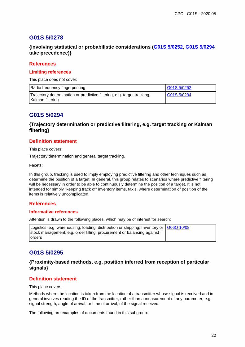
G01S 5/0278
{involving statistical or probabilistic considerations (G01S 5/0252, G01S 5/0294take precedence)}
References
Limiting references
This place does not cover:
Radio frequency fingerprinting G01S 5/0252
Trajectory determination or predictive filtering, e.g. target tracking,Kalman filtering
G01S 5/0294
G01S 5/0294
{Trajectory determination or predictive filtering, e.g. target tracking or Kalmanfiltering}
Definition statement
This place covers:
Trajectory determination and general target tracking.
Facets:
In this group, tracking is used to imply employing predictive filtering and other techniques such asdetermine the position of a target. In general, this group relates to scenarios where predictive filteringwill be necessary in order to be able to continuously determine the position of a target. It is notintended for simply "keeping track of" inventory items, taxis, where determination of position of theitems is relatively uncomplicated.
References
Informative references
Attention is drawn to the following places, which may be of interest for search:
Logistics, e.g. warehousing, loading, distribution or shipping; Inventory orstock management, e.g. order filling, procurement or balancing againstorders
G06Q 10/08
G01S 5/0295
{Proximity-based methods, e.g. position inferred from reception of particularsignals}
Definition statement
This place covers:
Methods where the location is taken from the location of a transmitter whose signal is received and ingeneral involves reading the ID of the transmitter, rather than a measurement of any parameter, e.g.signal strength, angle of arrival, or time of arrival, of the signal received.
The following are examples of documents found in this subgroup:
22

G01S 5/0295 (continued)Definition statement
CPC - G01S - 2020.05
• taking the position of receiver to be the position of an access point, when the receiver receives asignal from that access point;
• taking the position of a cellular phone to be that of the centre of the cell sector in which it findsitself.
Relationships with other classification places
It may be necessary to also consult G01S 5/02529 during search. The subject-matter of G01S 5/0295and G01S 5/02529 are not unlike one another. Where a list of identifiers is used purely to look up acorresponding position at which this combination was measured, a symbol in G01S 5/0252 (mostlylikely G01S 5/02529) is appropriate; however, where the determination of position is determined basedon the coordinates of the transmitters whose I.D. has been read, then a G01S 5/0295 symbol shouldbe allocated.
G01S 5/06
Position of source determined by co-ordinating a plurality of position linesdefined by path-difference measurements (G01S 5/12 takes precedence)
References
Limiting references
This place does not cover:
By co-ordinating position lines of different shape, e.g. hyperbolic, circular,elliptical, radial
G01S 5/12
G01S 5/10
Position of receiver fixed by co-ordinating a plurality of position lines definedby path-difference measurements {, e.g. omega or decca systems} (G01S 5/12takes precedence {; beacons and receivers cooperating therewith G01S 1/306,G01S 1/308})
References
Limiting references
This place does not cover:
By co-ordinating position lines of different shape, e.g. hyperbolic, circular,elliptical, radial
G01S 5/12
Informative references
Attention is drawn to the following places, which may be of interest for search:
Beacons and receivers cooperating therewith G01S 1/306, G01S 1/308
Glossary of terms
In this place, the following terms or expressions are used with the meaning indicated:
Omega Radio navigation operating in the 10kHz-14kHz employinghyperbolic techniques
23
G01S 5/10 (continued)Glossary of terms
CPC - G01S - 2020.05
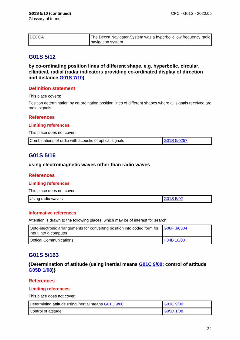
DECCA The Decca Navigator System was a hyperbolic low frequency radionavigation system
G01S 5/12
by co-ordinating position lines of different shape, e.g. hyperbolic, circular,elliptical, radial (radar indicators providing co-ordinated display of directionand distance G01S 7/10)
Definition statement
This place covers:
Position determination by co-ordinating position lines of different shapes where all signals received areradio signals.
References
Limiting references
This place does not cover:
Combinations of radio with acoustic of optical signals G01S 5/0257
G01S 5/16
using electromagnetic waves other than radio waves
References
Limiting references
This place does not cover:
Using radio waves G01S 5/02
Informative references
Attention is drawn to the following places, which may be of interest for search:
Opto-electronic arrangements for converting position into coded form forinput into a computer
G06F 3/0304
Optical Communications H04B 10/00
G01S 5/163
{Determination of attitude (using inertial means G01C 9/00; control of attitudeG05D 1/08)}
References
Limiting references
This place does not cover:
Determining attitude using inertial means G01C 9/00 G01C 9/00
Control of attitude G05D 1/08
24
G01S 5/163 (continued) CPC - G01S - 2020.05
Informative references
Attention is drawn to the following places, which may be of interest for search:
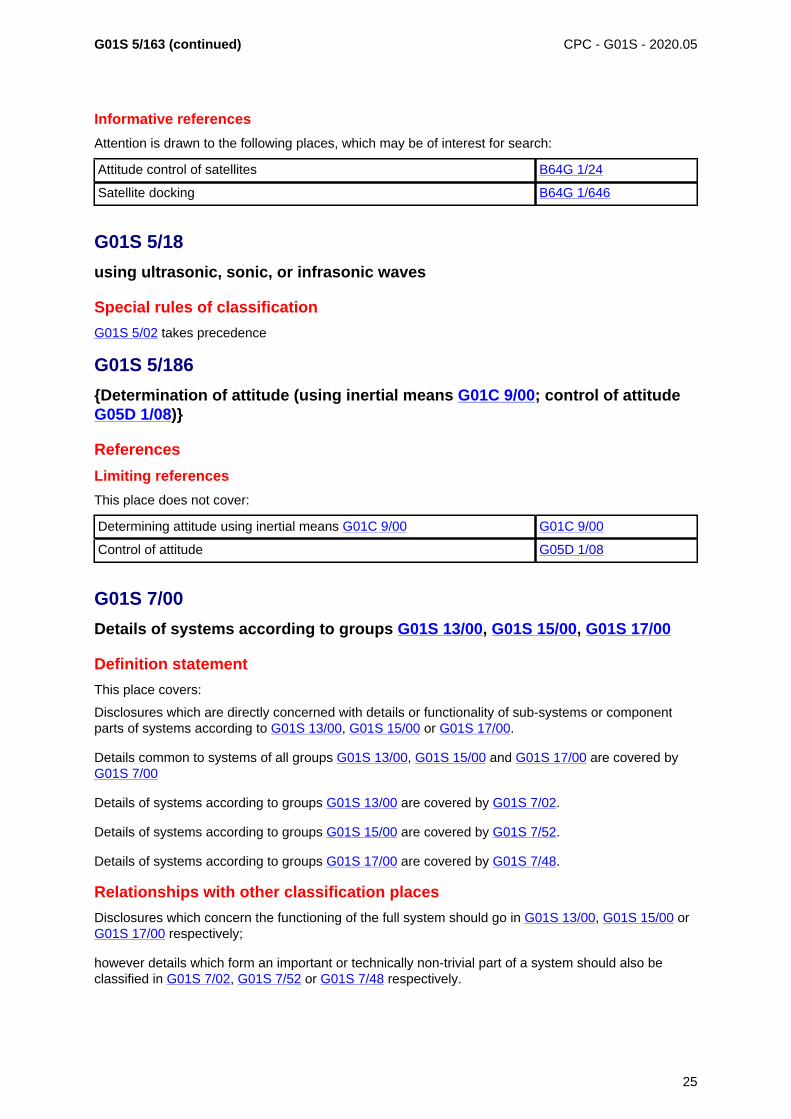
Attitude control of satellites B64G 1/24
Satellite docking B64G 1/646
G01S 5/18
using ultrasonic, sonic, or infrasonic waves
Special rules of classification
G01S 5/02 takes precedence
G01S 5/186
{Determination of attitude (using inertial means G01C 9/00; control of attitudeG05D 1/08)}
References
Limiting references
This place does not cover:
Determining attitude using inertial means G01C 9/00 G01C 9/00
Control of attitude G05D 1/08
G01S 7/00
Details of systems according to groups G01S 13/00, G01S 15/00, G01S 17/00
Definition statement
This place covers:
Disclosures which are directly concerned with details or functionality of sub-systems or componentparts of systems according to G01S 13/00, G01S 15/00 or G01S 17/00.
Details common to systems of all groups G01S 13/00, G01S 15/00 and G01S 17/00 are covered byG01S 7/00
Details of systems according to groups G01S 13/00 are covered by G01S 7/02.
Details of systems according to groups G01S 15/00 are covered by G01S 7/52.
Details of systems according to groups G01S 17/00 are covered by G01S 7/48.
Relationships with other classification places
Disclosures which concern the functioning of the full system should go in G01S 13/00, G01S 15/00 orG01S 17/00 respectively;
however details which form an important or technically non-trivial part of a system should also beclassified in G01S 7/02, G01S 7/52 or G01S 7/48 respectively.
25
G01S 7/00 (continued) CPC - G01S - 2020.05
References
Informative references
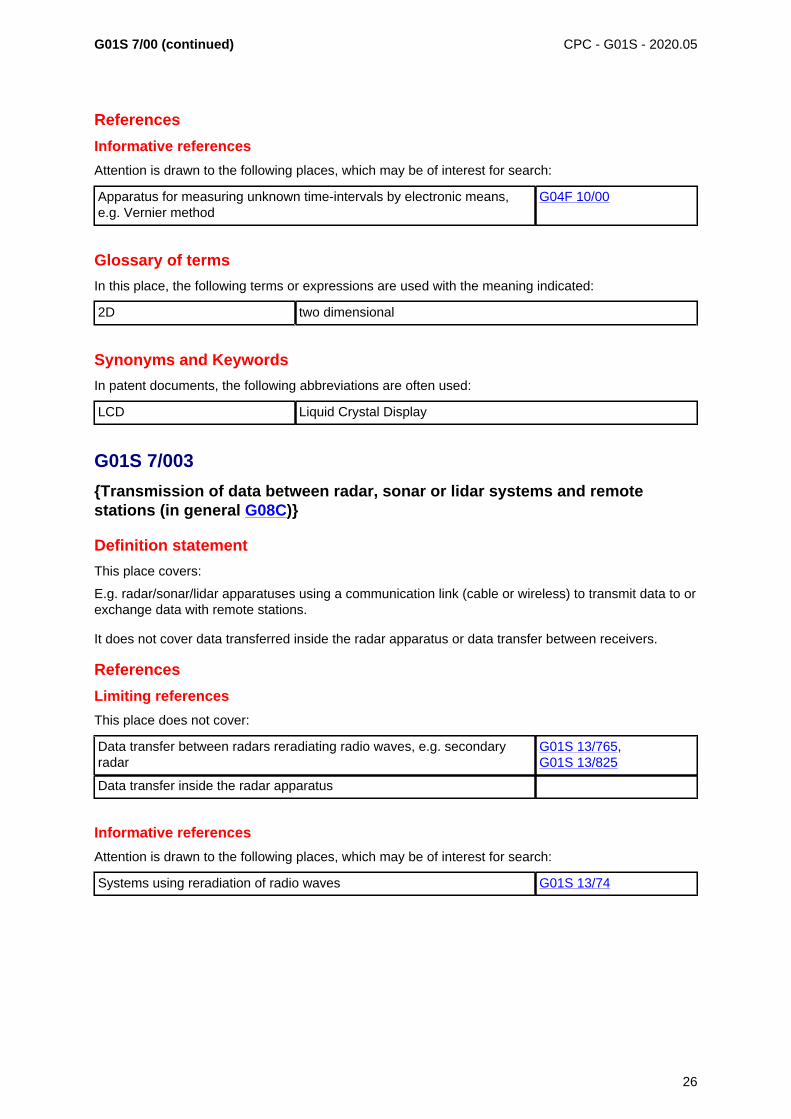
Attention is drawn to the following places, which may be of interest for search:
Apparatus for measuring unknown time-intervals by electronic means,e.g. Vernier method
G04F 10/00
Glossary of terms
In this place, the following terms or expressions are used with the meaning indicated:
2D two dimensional
Synonyms and Keywords
In patent documents, the following abbreviations are often used:
LCD Liquid Crystal Display
G01S 7/003
{Transmission of data between radar, sonar or lidar systems and remotestations (in general G08C)}
Definition statement
This place covers:
E.g. radar/sonar/lidar apparatuses using a communication link (cable or wireless) to transmit data to orexchange data with remote stations.
It does not cover data transferred inside the radar apparatus or data transfer between receivers.
References
Limiting references
This place does not cover:
Data transfer between radars reradiating radio waves, e.g. secondaryradar
G01S 13/765,G01S 13/825
Data transfer inside the radar apparatus
Informative references
Attention is drawn to the following places, which may be of interest for search:
Systems using reradiation of radio waves G01S 13/74
26
CPC - G01S - 2020.05
G01S 7/006
{using shared front-end circuitry, e.g. antennas (G01S 13/765, G01S 13/825 takeprecedence)}
Definition statement
This place covers:
• E.g. radar/sonar/lidar apparatuses using their beam / antenna to communicate (wirelessly) with aremote station.
• Communication equipment using the communication signals for distance determination, e.g. viatime-of-flight.
References
Limiting references
This place does not cover:
Data transfer between radars reradiating radio waves, e.g. secondaryradar
G01S 13/765,G01S 13/825
Informative references
Attention is drawn to the following places, which may be of interest for search:
Systems using reradiation of radio waves G01S 13/74
G01S 7/02
of systems according to group G01S 13/00
Definition statement
This place covers:
Disclosures which are directly concerned with details or functionality of sub-systems or componentparts of systems according to G01S 13/00.
Relationships with other classification places
Disclosures which concern the functioning of the full system should go in G01S 13/00; howeverdetails which form an important or technically non-trivial part of a system should also be classified inG01S 7/02.
References
Limiting references
This place does not cover:
Radio wave modulation schemes G01S 13/08, G01S 13/58
Beam-forming G01S 13/42, H01Q 3/00
Tracking G01S 13/66
Specific radar applications G01S 13/88
27
G01S 7/02 (continued) CPC - G01S - 2020.05
Special rules of classification
The subgroup G01S 7/28 covers details of pulse systems whereas the subgroup G01S 7/35covers details of non-pulse systems. This distinction is made in accordance with the subgroups ofG01S 13/08 and G01S 13/58. All other subgroups of G01S 7/02 are applicable to both pulse and non-pulse systems.
G01S 7/021
{Auxiliary means for detecting or identifying radar signals or the like, e.g. radarjamming signals (multi-channel PRF-analysers, per se G01R 23/155)}
Definition statement
This place covers:
Detection or identification of
• radar signals or
• other signals in the context of radar, e.g. radar jamming signals.
The use of said information e.g. for anti-jamming or EMI reduction measures is covered by otherclasses (see below).
References
Limiting references
This place does not cover:
Means for anti-jamming, e.g. ECCM, i.e. electronic counter-countermeasures.
G01S 7/36
Jamming means, e.g. producing false echoes G01S 7/38
G01S 7/022
{Road traffic radar detectors}
Definition statement
This place covers:
• Vehicle based detectors for detecting police roadside radars, fixed overhead radars etc.
• The use of said information e.g. jamming the police radar or other measures is covered by otherclasses (see below).
References
Limiting references
This place does not cover:
Jamming means, e.g. producing false echoes G01S 7/38
Informative references
Attention is drawn to the following places, which may be of interest for search:
Radar or analogous systems, designed for traffic control G01S 13/91
For velocity measurement G01S 13/92
28
G01S 7/022 (continued)Informative references
CPC - G01S - 2020.05
Traffic control systems for road vehicles G08G 1/00
Detecting movement of traffic to be counted or controlled G08G 1/01
G01S 7/03
Details of HF subsystems specially adapted therefor, e.g. common totransmitter and receiver
Definition statement
This place covers:
Radar-related constructional details of HF (i.e. high frequency)-subsystems.
Relationships with other classification places
Details of waveguides, waveguide transitions, couplers (like hybrid couplers etc.) should be classifiedadditionally in H01P, details of antennas should be classified additionally in H01Q, details of oscillators(e.g. VCO, i.e. voltage controlled oscillator, DRO, i.e. dielectric resonator oscillator), resonators,modulators/demodulators (like mixers, switches etc.), amplifiers, impedance matching networks etc.should be classified additionally in H03.
References
Informative references
Attention is drawn to the following places, which may be of interest for search:
Schematics of pulsed transmitters G01S 7/282
Schematics of non-pulsed transmitters G01S 7/35
TR boxes H01J 17/64
Details of HF(i.e. high frequency)-components per se H01P, H01Q, H03
Impedance networks or resonators H03H
G01S 7/032
{Constructional details for solid-state radar subsystems}
Definition statement
This place covers:
E.g. solid state Tx/Rx-modules, single-chip radar sensors etc.
G01S 7/038
{Feedthrough nulling circuits}
Definition statement
This place covers:
Circuits or measures to suppress Tx-Rx-crosstalk.
29
CPC - G01S - 2020.05
G01S 7/04
Display arrangements
Definition statement
This place covers:
All details of radar displays and the respective data processing.
G01S 7/06
Cathode-ray tube displays {or other two-dimensional or three-dimensionaldisplays (cathode ray oscilloscopes in general G01R 13/20)}
Definition statement
This place covers:
Not only details of cathode-ray tube displays (old technique from the days of generating this IPCclass) but details of all kind of displays; such details are e.g. the use of different colours, cursor lines,symbols, plan-position indicators etc.
G01S 7/28
Details of pulse systems
Definition statement
This place covers:
The respective details (e.g. schematics) of radars using a pulsed carrier wave
References
Limiting references
This place does not cover:
Constructional features of the pulsed radar (like a certain waveguide typeused etc.)
G01S 7/03
G01S 7/2813
{Means providing a modification of the radiation pattern for cancellingnoise, clutter or interfering signals, e.g. side lobe suppression, side lobeblanking, null-steering arrays (specially adapted to secondary radar systemsG01S 13/762; aerials or aerials systems H01Q 21/29, H01Q 25/00)}
Definition statement
This place covers:
Methods or means for a pulsed radar system providing a modification of the radiation pattern forcancelling noise, clutter or interfering signals, e.g. side lobe suppression, side lobe blanking, null-steering arrays.
30
G01S 7/2813 (continued) CPC - G01S - 2020.05
References
Limiting references
This place does not cover:
By using shape of radiation pattern G01S 7/2925
Modification of radiation pattern specially adapted to secondary radarsystems
G01S 13/762
Null steering specially adapted to phased arrays in general H01Q 3/2611
Aerials or aerials systems as such H01Q 21/29, H01Q 25/00
Informative references
Attention is drawn to the following places, which may be of interest for search:
See also "extracting wanted echo signals based on data belonging to anumber of consecutive radar periods in pulsed radar by using the shapeof the radiation pattern"
G01S 7/2925
See also "simultaneous measurement of distance and other coordinates" G01S 13/42
Modification of radiation pattern specially adapted to secondary radarsystems
G01S 13/762
Null steering specially adapted to phased arrays in general H01Q 3/2611
Aerials or aerials systems as such H01Q 21/29, H01Q 25/00
Special rules of classification
These features may likewise apply to non-pulse systems, i.e. G01S 7/35. In the case of non-pulsesystems having said features, give both classes, G01S 7/35 and G01S 7/2813.
G01S 7/282
Transmitters
Definition statement
This place covers:
Schematics, circuit details of pulsed radar transmitters
Relationships with other classification places
Circuits for generating electric pulses per se (for all applications, not only radar) are in H03K 3/00
References
Limiting references
This place does not cover:
Constructional features of the transmitter (like a certain waveguide typeused etc.)
G01S 7/03
31
G01S 7/282 (continued) CPC - G01S - 2020.05
Informative references
Attention is drawn to the following places, which may be of interest for search:
Pulse technique H03K
G01S 7/292
Extracting wanted echo-signals
Definition statement
This place covers:
Details of echo extraction in pulsed radars.
References
Informative references
Attention is drawn to the following places, which may be of interest for search:
Doppler systems G01S 13/50
Pulsed radars discriminating between fixed and moving objects (e.g. withmoving target indication (MTI), adaptive clutter cancellation, etc.)
G01S 13/52
Special rules of classification
Pulsed systems measuring target Doppler but also containing disclosure pertaining to extractingwanted targets from noise are classified in both G01S 13/52 and G01S 7/292.
G01S 7/2921
{based on data belonging to one radar period}
Definition statement
This place covers:
Details of echo extraction based on data belonging to single radar period in pulsed radars.
G01S 7/2922
{by using a controlled threshold}
Definition statement
This place covers:
e.g. CFAR
G01S 7/2925
{by using shape of radiation pattern}
Definition statement
This place covers:
Details of echo extraction based on data belonging to a number of consecutive radar periods in pulsedradars using the shape of radiation pattern.
32
G01S 7/2925 (continued) CPC - G01S - 2020.05
References
Limiting references
This place does not cover:
Modification of radiation pattern specially adapted to secondary radarsystems
G01S 13/762
Null steering specially adapted to phased arrays in general H01Q 3/2611
Aerials or aerials systems as such H01Q 21/29, H01Q 25/00
Informative references
Attention is drawn to the following places, which may be of interest for search:
See also "means for a pulsed radar system providing a modification ofthe radiation pattern for cancelling noise, clutter or interfering signals, e.g.side lobe suppression, side lobe blanking, null-steering arrays"
G01S 7/2813
See also "simultaneous measurement of distance and other coordinates" G01S 13/42
Modification of radiation pattern specially adapted to secondary radarsystems
G01S 13/762
Null steering specially adapted to phased arrays in general H01Q 3/2611
Aerials or aerials systems as such H01Q 21/29, H01Q 25/00
Special rules of classification
These features may likewise apply to non-pulse systems, i.e. G01S 7/35. In that case give bothclasses, G01S 7/35 and G01S 7/2925.
G01S 7/2927
{by deriving and controlling a threshold value}
Definition statement
This place covers:
e.g. CFAR
G01S 7/295
Means for transforming co-ordinates or for evaluating data, e.g. usingcomputers
Definition statement
This place covers:
E.g., converting polar to Cartesian coordinates, details of computer implemented receivers.
References
Limiting references
This place does not cover:
Methods for processing data to evaluate functions by calculation per se G06F 7/48
33
CPC - G01S - 2020.05
G01S 7/298
Scan converters
References
Informative references
Attention is drawn to the following places, which may be of interest for search:
Scan converters for sonar receivers G01S 7/531
G01S 7/34
Gain of receiver varied automatically during pulse-recurrence period, e.g. anti-clutter gain control
References
Limiting references
This place does not cover:
Amplifiers per se H03F
Automatic gain control in amplifiers per se H03G 3/20
Informative references
Attention is drawn to the following places, which may be of interest for search:
Gain control in sonar receivers G01S 7/529
G01S 7/35
Details of non-pulse systems
Definition statement
This place covers:
Details (e.g. of schematics) of non-pulsed radar systems, e.g. FMCW or CW radar systems.
References
Limiting references
This place does not cover:
Constructional features of the non-pulsed radar (like a certain waveguidetype used etc.)
G01S 7/03
34
CPC - G01S - 2020.05
G01S 7/36
Means for anti-jamming {, e.g. electronic counter-counter measures [ECCM](G01S 7/2813 takes precedence; identification of radar jamming signalsG01S 7/021; random interference pulse cancellers G01S 7/2928)}
Definition statement
This place covers:
Means and measures to counter a jamming attack on the radar.
References
Limiting references
This place does not cover:
Detection of jamming signals G01S 7/021
Means providing a modification of the radiation pattern for cancellingnoise, clutter or interfering signals, e.g. side lobe suppression, side lobeblanking, null-steering arrays
G01S 7/2813
Random interference pulse cancellers G01S 7/2928
G01S 7/38
Jamming means, e.g. producing false echoes {(identification of radar signalsG01S 7/021)}
Definition statement
This place covers:
Radar jammers (active and passive) and similar means
References
Limiting references
This place does not cover:
Identification of radar signals G01S 7/021
Informative references
Attention is drawn to the following places, which may be of interest for search:
Reflecting surfaces comprising a plurality of reflecting particles, e.g. chaff H01Q 15/145
G01S 7/40
Means for monitoring or calibrating
Definition statement
This place covers:
Means and measures to
35
G01S 7/40 (continued)Definition statement
CPC - G01S - 2020.05
• monitor the (correct) operating status of the radar, e.g. detection of failure, malfunction etc. of Tx-and/or Rx-modules or detection of obstruction of the antenna e.g. by ice, dirt etc., or
• calibrating the radar system e.g. in separate calibration cycles or during operation, intermittentlyor for each echo, manually or automatically, by internal or external reference; e.g. an internalreference line or an external reflector of known location.
G01S 7/4004
{of parts of a radar system (see provisionally also G01S 7/40)}
Definition statement
This place covers:
Monitoring and calibrating parts of the radar system.
Since monitoring and calibrating of a radar (G01S 7/40) inevitably involves the monitoring andcalibrating of the parts of the radar system, this class (G01S 7/4004) is regarded as ill-conceived andhas to be reformulated/deleted in the near future. To ensure that all documents are found, see alsoG01S 7/40 and the classes G01S 7/4008 - G01S 7/4026).
References
Informative references
Attention is drawn to the following places, which may be of interest for search:
To ensure that all documents are found, see also: G01S 7/40 andG01S 7/4008 -G01S 7/4026
Special rules of classification
This class is not used, and is awaiting revision.
G01S 7/4008
{of transmitters}
Definition statement
This place covers:
Monitoring and calibrating the transmitter of the radar system.
Since monitoring and calibrating of the parts of the radar system (G01S 7/4004) inevitably involvesthe monitoring and calibrating of the transmitter of the radar system, it is recommended to consult alsoG01S 7/4004 for a complete search. The same applies to G01S 7/4017 (HF systems) in which alsosome documents with transmitter monitoring/calibrating may be hidden.
References
Informative references
Attention is drawn to the following places, which may be of interest for search:
To ensure that all documents are found, see also: G01S 7/4004 andG01S 7/4017
36
CPC - G01S - 2020.05
G01S 7/4017
{of HF systems}
Definition statement
This place covers:
Monitoring and calibrating the HF systems of the radar system.
Since monitoring and calibrating of the HF systems of the radar system inevitably overlaps with themonitoring and calibrating of the transmitter (G01S 7/4008) and / or the receiver (G01S 7/4021) of theradar system, it is recommended to consult also these classes for a complete search.
This class (G01S 7/4017) is regarded as ill-conceived and has to be reformulated/deleted in the nearfuture.
References
Informative references
Attention is drawn to the following places, which may be of interest for search:
To ensure that all documents are found, see also: G01S 7/4008,G01S 7/4021
Special rules of classification
This class is not used, and is awaiting revision.
G01S 7/4021
{of receivers}
Definition statement
This place covers:
Monitoring and calibrating the receiver of the radar system.
Since monitoring and calibrating of the parts of the radar system (G01S 7/4004) inevitably involvesthe monitoring and calibrating of the receiver of the radar system, it is recommended to consult alsoG01S 7/4004 for a complete search. The same applies to G01S 7/4017 (HF systems) in which alsosome document with transmitter monitoring/calibrating may be hidden.
References
Informative references
Attention is drawn to the following places, which may be of interest for search:
To ensure that all documents are found, see also: G01S 7/4004,G01S 7/4017
37
CPC - G01S - 2020.05
G01S 7/4026
{Antenna boresight}
Definition statement
This place covers:
• The monitoring and (re-)adjusting of the antenna boresight.
• The monitoring / checking of the antenna boresight is done e.g. either by observing the history/speed/vector etc. of targets during operation (i.e. adaptively) or by manually checking the boresightin a calibration environment.
• The adjustment is done e.g. either by steering the antenna or the antenna beam in the correctpointing position (mechanically, electronically etc.) or by re-calculating the target positions in thepost-processing.
G01S 7/4052
{by simulation of echoes (analogue simulators in general G06G 7/78)}
Definition statement
This place covers:
All kinds of radar echo simulation, be it by an internal reference line, be it by external reflectors, e.g.passive of active reflectors, being e.g. either moved or modulated respectively for Doppler-simulationetc.
References
Limiting references
This place does not cover:
Systems in general using reradiation of radio waves G01S 13/74
Special rules of classification
Example:
An internal reference/delay line in the receiver for generating a distance calibration, e.g. for each echo,would be classified not only in G01S 7/4052 but also in G01S 7/4021 (calibrating the receiver).
G01S 7/4056
{specially adapted to FMCW}
Definition statement
This place covers:
Simulation of echoes in or for FMCW radars, e.g. internal reference/delay lines for distance calibrationor external frequency modulated active reflectors etc.
Special rules of classification
Example:
An internal reference/delay line in the receiver for generating a distance calibration, e.g. for each echo,would be classified not only in G01S 7/4052 but also in G01S 7/4021 (calibrating the receiver)
38
CPC - G01S - 2020.05
G01S 7/414
{Discriminating targets with respect to background clutter}
References
Limiting references
This place does not cover:
Pulsed radars discriminating between fixed and moving objects andhaving adaptive clutter cancellation
G01S 13/5244
Informative references
Attention is drawn to the following places, which may be of interest for search:
Pulsed radars discriminating between fixed and moving objects andhaving adaptive clutter cancellation
G01S 13/5244
Special rules of classification
G01S 13/5244 takes precedence
G01S 7/415
{Identification of targets based on measurements of movement associated withthe target}
References
Limiting references
This place does not cover:
Pulsed radars discriminating between fixed and moving objects andhaving moving target indicator (MTI)
G01S 13/524
--- based upon the phase or frequency shift resulting from movement ofobjects, with reference to the transmitted signals, e.g. coherent MT
G01S 13/524
Informative references
Attention is drawn to the following places, which may be of interest for search:
Pulsed radars discriminating between fixed and moving objects andhaving moving target indicator (MTI)
G01S 13/524
G01S 7/418
{Theoretical aspects}
Definition statement
This place covers:
The theoretical aspects (e.g. equations etc.) involved in target characterisation.
39
CPC - G01S - 2020.05
G01S 7/42
Diversity systems specially adapted for radar
Definition statement
This place covers:
Diversity means redundancy, e.g. of components or features: For example a plurality of redundant Tx/Rx-modules, antennas, beams, tilt angles or frequency ranges to be used to ensure target detection(e.g. under jamming, interference or combat conditions).
G01S 7/48
of systems according to group G01S 17/00
Definition statement
This place covers:
Details of systems which do not have a specific entry in lower groups, but which are includedin the inventive concept of the disclosure, or which do have a specific entry in lower groups butare combinations of such details features, and where classification of each feature individually isinappropriate, should be classified here. disclosures which are directly concerned with details orfunctionality of sub-systems or component parts of systems according to G01S 17/00.
Relationships with other classification places
Disclosures which concern the functioning of the full system should go in G01S 17/00; however detailsof systems which form an important or technically non-trivial part of a disclosure of a system shouldalso be classified in G01S 7/48.
References
Limiting references
This place does not cover:
Ammunition fuzes operated by light or similar radiation F42C 13/02
(constructional) details of optical interferometers G01B 9/00
Measuring polarisation of light G01J
Optical scanners per se G02B 26/00
Optical fibres per se G02B 6/00
Optical lenses and objectives per se G02B 9/00
(constructional) features of semiconductor devices H01L 23/00, H01L 31/00
(constructional) features of lasers H01S 3/00, H01S 5/00
Application-oriented references
Examples of places where the subject matter of this place is covered when specially adapted, used fora particular purpose, or incorporated in a larger system:
Systems per se are classified in G01S 17/00
40
G01S 7/48 (continued) CPC - G01S - 2020.05
Informative references
Attention is drawn to the following places, which may be of interest for search:
Optical signalling in vehicles B60Q
Vehicle fittings B60R
Optical interferometers G01B 9/00
Optical arrangements G02B
(acousto-)optical modulators G02F
Special rules of classification
Details of disclosures of systems which form a technically important or technically non-trivial part of adisclosure should be classified in G01S 7/48, as well as the appropriate system group in G01S 17/00,especially if these details form a significant part of the disclosure, and do not concern well-known andwidely retrievable subject-matter.
Glossary of terms
In this place, the following terms or expressions are used with the meaning indicated:
2D means two dimensional
Synonyms and Keywords
In patent documents, the following abbreviations are often used:
LCD Liquid Crystal Display
G01S 7/4804
{Auxiliary means for detecting or identifying lidar signals or the like, e.g. laserilluminators}
Definition statement
This place covers:
Detection or identification of
• lidar signals or
• other signals in the context of lidar, e.g. laser jamming, laser designator, or high power destructivelight beams.
References
Limiting references
This place does not cover:
Means for jamming, anti-jamming, e.g. ECM, i.e. electronic counter-measures: ECCM, i.e. electronic counter-counter-measures: electro-optical counter-(counter)-measures.
G01S 7/495
41
CPC - G01S - 2020.05
G01S 7/4806
{Road traffic laser detectors}
Definition statement
This place covers:
Vehicle based detectors for detecting police roadside lidars, fixed overhead lidars etc.
The use of said information e.g. jamming the police lidar or other measures is covered by otherclasses (see below).
References
Limiting references
This place does not cover:
Jamming means, e.g. producing false echoes G01S 7/495
Informative references
Attention is drawn to the following places, which may be of interest for search:
Radar or analogous systems, designed for traffic control G01S 13/91
For velocity measurement G01S 13/92
Traffic control systems for road vehicles G08G 1/00
Detecting movement of traffic to be counted or controlled G08G 1/01
G01S 7/481
Constructional features, e.g. arrangements of optical elements
Definition statement
This place covers:
All aspects of mechanical features, of physical layouts and component details where these arerelevant, and which do not have a specific entry in lower groups, but which are included in theinventive concept of the disclosure, or which do have a specific entry in lower groups but arecombinations of such details features, and where classification of each feature individually isinappropriate.
References
Limiting references
This place does not cover:
Arrangements of lenses and optical elements per se G02B 1/00 - G02B 5/00,G02B 13/00 -G02B 25/00, G02B 27/00
Optical scanners per se G02B 26/00
42
CPC - G01S - 2020.05
G01S 7/4811
{common to transmitter and receiver}
Definition statement
This place covers:
All aspects of mechanical features, of physical layouts involving both transmitter and receiver, wherethese are non-trivial, and which do not have a specific entry in lower groups, but which are includedin the inventive concept of the disclosure, or which do have a specific entry in lower groups butare combinations of such details features, and where classification of each feature individually isinappropriate.
G01S 7/4812
{transmitted and received beams following a coaxial path}
Definition statement
This place covers:
Arrangements where at least a part of the measurement beam is guided coaxially for transmission andreception.
G01S 7/4813
{Housing arrangements}
Definition statement
This place covers:
Enclosing means, structural and supporting means both internal and external.
References
Limiting references
This place does not cover:
Printed circuits; casings or constructional details of electric apparatus;manufacture of assemblages of electrical components, per se.
H05K
G01S 7/4814
{of transmitters alone}
Relationships with other classification places
Constructional details of sources of illumination per se F21, H01J, H01K, H01L 33/00
Constructional details of lasers; devices using stimulatedemission, per se
H01S
43

CPC - G01S - 2020.05
G01S 7/4816
{of receivers alone}
Relationships with other classification places
Constructional details of photo sensitive detectors per se G01J 5/00 - G01J 11/00
Constructional details of photo-sensitive semiconductor devicesper se
H01L 31/00
Constructional details of imaging devices, e.g. CCD's, per se H01L 27/00, H04N 5/30
G01S 7/4818
{using optical fibres}
Definition statement
This place covers:
Transmitting lidar signals at least partially through optically conducting light guides e.g., optical fibres.
References
Limiting references
This place does not cover:
Light guides per se G02B 6/00
G01S 7/483
Details of pulse systems
Definition statement
This place covers:
Details including circuit details (circuit diagrams) of lidars, ladars, optical rangefinders using pulsedcarrier waves.
G01S 7/484
Transmitters
Relationships with other classification places
Sources of optical illumination per se F21, H01J, H01K, H01L 33/00
Devices using stimulated emission, per se H01S
Circuits for generating electric pulses per se H03K 3/00
44
G01S 7/484 (continued) CPC - G01S - 2020.05
References
Limiting references
This place does not cover:
Constructional features of the transmitter (like a certain opticalarrangement or type used etc.)
G01S 7/4814
G01S 7/486
Receivers
Definition statement
This place covers:
Details including circuit details (circuit diagrams) of receiving devices used in lidars, ladars, opticalrangefinders using pulsed carrier waves.
Relationships with other classification places
Details of photo sensitive detectors including semiconductordevices per se
G01J, H01L
Image intensifiers G02B 23/12
Light transforming elements per se H01J, H01L
Imaging devices, e.g. CCD's, H01L 27/00, H04N 5/30
G01S 7/487
Extracting wanted echo signals {, e.g. pulse detection}
Definition statement
This place covers:
Details of echo extraction in pulsed lidars (ladars).
References
Limiting references
This place does not cover:
Pulsed lidars (ladars) discriminating between fixed and moving objects(e.g. with moving target indication, adaptive clutter cancellation, etc.
G01S 17/50
Informative references
Attention is drawn to the following places, which may be of interest for search:
Pulsed lidars (ladars) discriminating between fixed and moving objectsetc.
G01S 17/50
45
CPC - G01S - 2020.05
G01S 7/489
Gain of receiver varied automatically during pulse-recurrence period
References
Limiting references
This place does not cover:
Gain control of amplifiers per se H03F
Informative references
Attention is drawn to the following places, which may be of interest for search:
Gain control of radar receivers G01S 7/34
G01S 7/491
Details of non-pulse systems
Definition statement
This place covers:
Details including circuit details (circuit diagrams) of lidars, ladars, optical rangefinders using non-pulsed carrier waves.
References
Informative references
Attention is drawn to the following places, which may be of interest for search:
Pulsed lidars (ladars) discriminating between fixed and moving objects,e.g. with moving target indication, adaptive clutter cancellation
G01S 17/50
G01S 7/493
Extracting wanted echo signals
Definition statement
This place covers:
Details of echo extraction and signal information relating to distance between transmitter and receiverin non-pulsed lidars (ladars).
G01S 7/495
Counter-measures or counter-counter-measures {using electronic or electro-optical means}
Definition statement
This place covers:
Means and measures to carry out OR to counter a jamming attack.
46
G01S 7/495 (continued) CPC - G01S - 2020.05
References
Limiting references
This place does not cover:
Detection of jamming signals G01S 7/4804
G01S 7/497
Means for monitoring or calibrating
Definition statement
This place covers:
Means and measures to:
• Monitor the (correct) operating status of the lidar, e.g. detection of failure, malfunction etc. of Tx-and/or Rx-modules or detection of obstruction of the beam path, e.g. by ice, dirt etc., or to:
• Calibrate the lidar system (e.g. in separate calibration cycles or during operation, intermittentlyor for each echo, manually or automatically, by internal or external reference; e.g. an internalreference line, an internal optical waveguide, or an external reflector of known location.
G01S 7/4972
{Alignment of sensor}
Definition statement
This place covers:
The monitoring and (re-)adjusting of the transmitted and/or received beam direction.
G01S 7/499
using polarisation effects
References
Informative references
Attention is drawn to the following places, which may be of interest for search:
Measuring polarisation of light G01J
G01S 7/51
Display arrangements
Definition statement
This place covers:
All forms of visual, audible or tactile display.
47
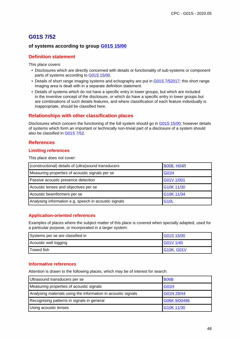
CPC - G01S - 2020.05
G01S 7/52
of systems according to group G01S 15/00
Definition statement
This place covers:
• Disclosures which are directly concerned with details or functionality of sub-systems or componentparts of systems according to G01S 15/00.
• Details of short range imaging systems and echography are put in G01S 7/52017; this short rangeimaging area is dealt with in a separate definition statement.
• Details of systems which do not have a specific entry in lower groups, but which are includedin the inventive concept of the disclosure, or which do have a specific entry in lower groups butare combinations of such details features, and where classification of each feature individually isinappropriate, should be classified here.
Relationships with other classification places
Disclosures which concern the functioning of the full system should go in G01S 15/00; however detailsof systems which form an important or technically non-trivial part of a disclosure of a system shouldalso be classified in G01S 7/52.
References
Limiting references
This place does not cover:
(constructional) details of (ultra)sound transducers B06B, H04R
Measuring properties of acoustic signals per se G01H
Passive acoustic presence detection G01V 1/001
Acoustic lenses and objectives per se G10K 11/30
Acoustic beamformers per se G10K 11/34
Analysing information e.g. speech in acoustic signals G10L
Application-oriented references
Examples of places where the subject matter of this place is covered when specially adapted, used fora particular purpose, or incorporated in a larger system:
Systems per se are classified in G01S 15/00
Acoustic well logging G01V 1/40
Towed fish G10K, G01V
Informative references
Attention is drawn to the following places, which may be of interest for search:
Ultrasound transducers per se B06B
Measuring properties of acoustic signals G01H
Analysing materials using the information in acoustic signals G01N 29/44
Recognising patterns in signals in general G06K 9/00496
Using acoustic lenses G10K 11/30
48
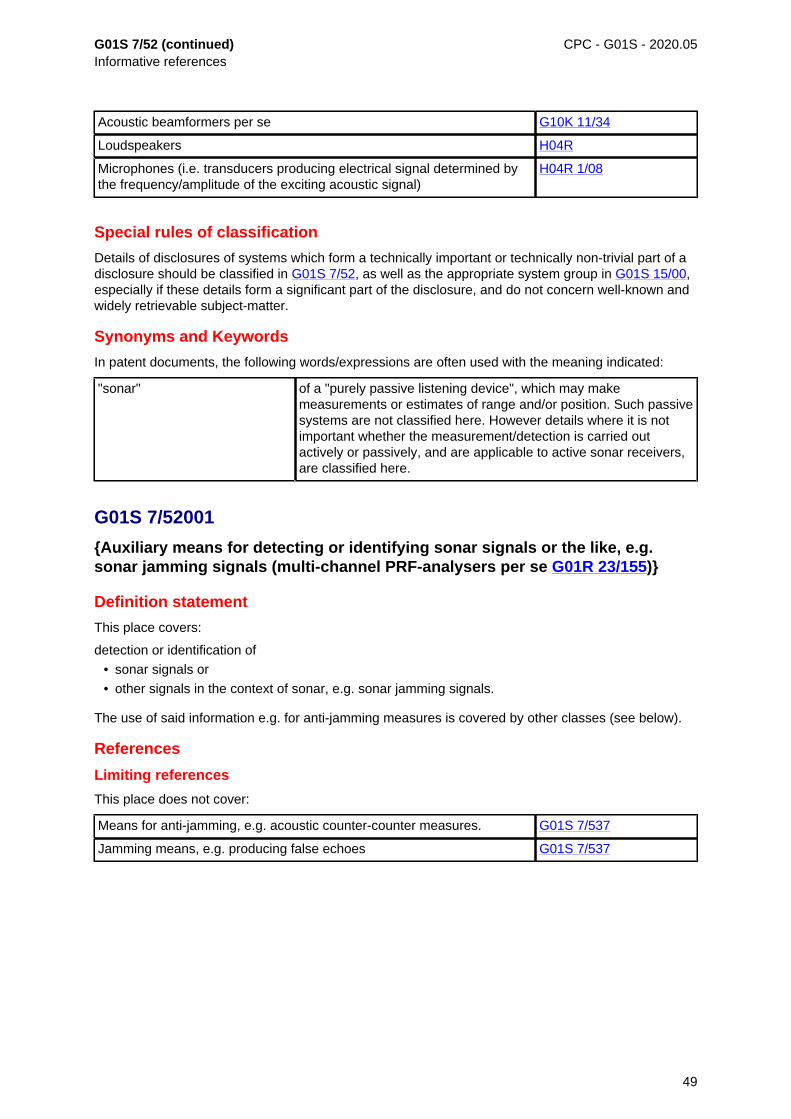
G01S 7/52 (continued)Informative references
CPC - G01S - 2020.05
Acoustic beamformers per se G10K 11/34
Loudspeakers H04R
Microphones (i.e. transducers producing electrical signal determined bythe frequency/amplitude of the exciting acoustic signal)
H04R 1/08
Special rules of classification
Details of disclosures of systems which form a technically important or technically non-trivial part of adisclosure should be classified in G01S 7/52, as well as the appropriate system group in G01S 15/00,especially if these details form a significant part of the disclosure, and do not concern well-known andwidely retrievable subject-matter.
Synonyms and Keywords
In patent documents, the following words/expressions are often used with the meaning indicated:
"sonar" of a "purely passive listening device", which may makemeasurements or estimates of range and/or position. Such passivesystems are not classified here. However details where it is notimportant whether the measurement/detection is carried outactively or passively, and are applicable to active sonar receivers,are classified here.
G01S 7/52001
{Auxiliary means for detecting or identifying sonar signals or the like, e.g.sonar jamming signals (multi-channel PRF-analysers per se G01R 23/155)}
Definition statement
This place covers:
detection or identification of
• sonar signals or
• other signals in the context of sonar, e.g. sonar jamming signals.
The use of said information e.g. for anti-jamming measures is covered by other classes (see below).
References
Limiting references
This place does not cover:
Means for anti-jamming, e.g. acoustic counter-counter measures. G01S 7/537
Jamming means, e.g. producing false echoes G01S 7/537
49

CPC - G01S - 2020.05
G01S 7/52003
{Techniques for enhancing spatial resolution of targets (beam formers ingeneral G10K 11/34; G01S 7/52046 takes precedence)}
Definition statement
This place covers:
Methods or means for a sonar system providing a modification of the beam pattern for cancellingnoise, clutter or interfering signals.
References
Limiting references
This place does not cover:
Acoustic beam forming per se G10K 11/00
G01S 7/52004
{Means for monitoring or calibrating (short-range imaging G01S 7/5205)}
Definition statement
This place covers:
Means and measures to:
• monitor the (correct) operating status of the sonar, e.g. detection of failure, malfunction etc. of Tx-and/or Rx components or detection of obstruction of the beam path (e.g. by ice, dirt etc.), or to
• calibrate the sonar system (e.g. before installation, in separate calibration cycles or duringoperation, or for each echo, manually or automatically, by internal or external reference
References
Limiting references
This place does not cover:
Taking into account temperature effects G01S 7/52006
G01S 7/52006
{with provision for compensating the effects of temperature}
References
Limiting references
This place does not cover:
Measuring acoustic properties of acoustic transmission media related totemperature
G01H
50
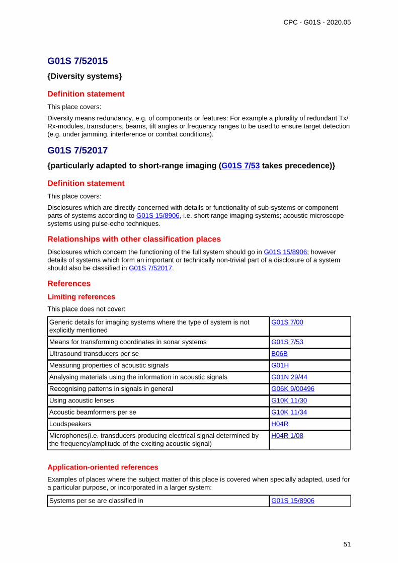
CPC - G01S - 2020.05
G01S 7/52015
{Diversity systems}
Definition statement
This place covers:
Diversity means redundancy, e.g. of components or features: For example a plurality of redundant Tx/Rx-modules, transducers, beams, tilt angles or frequency ranges to be used to ensure target detection(e.g. under jamming, interference or combat conditions).
G01S 7/52017
{particularly adapted to short-range imaging (G01S 7/53 takes precedence)}
Definition statement
This place covers:
Disclosures which are directly concerned with details or functionality of sub-systems or componentparts of systems according to G01S 15/8906, i.e. short range imaging systems; acoustic microscopesystems using pulse-echo techniques.
Relationships with other classification places
Disclosures which concern the functioning of the full system should go in G01S 15/8906; howeverdetails of systems which form an important or technically non-trivial part of a disclosure of a systemshould also be classified in G01S 7/52017.
References
Limiting references
This place does not cover:
Generic details for imaging systems where the type of system is notexplicitly mentioned
G01S 7/00
Means for transforming coordinates in sonar systems G01S 7/53
Ultrasound transducers per se B06B
Measuring properties of acoustic signals G01H
Analysing materials using the information in acoustic signals G01N 29/44
Recognising patterns in signals in general G06K 9/00496
Using acoustic lenses G10K 11/30
Acoustic beamformers per se G10K 11/34
Loudspeakers H04R
Microphones(i.e. transducers producing electrical signal determined bythe frequency/amplitude of the exciting acoustic signal)
H04R 1/08
Application-oriented references
Examples of places where the subject matter of this place is covered when specially adapted, used fora particular purpose, or incorporated in a larger system:
Systems per se are classified in G01S 15/8906
51
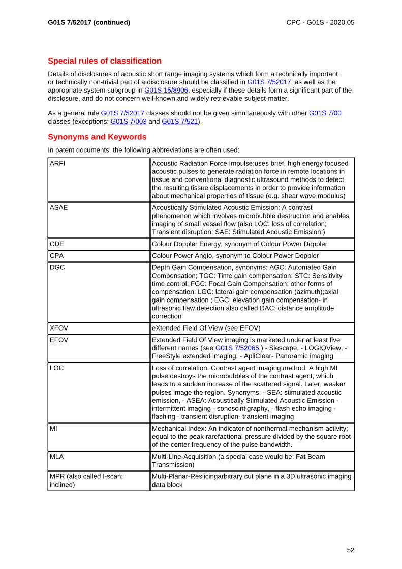
G01S 7/52017 (continued) CPC - G01S - 2020.05
Special rules of classification
Details of disclosures of acoustic short range imaging systems which form a technically importantor technically non-trivial part of a disclosure should be classified in G01S 7/52017, as well as theappropriate system subgroup in G01S 15/8906, especially if these details form a significant part of thedisclosure, and do not concern well-known and widely retrievable subject-matter.
As a general rule G01S 7/52017 classes should not be given simultaneously with other G01S 7/00classes (exceptions: G01S 7/003 and G01S 7/521).
Synonyms and Keywords
In patent documents, the following abbreviations are often used:
ARFI Acoustic Radiation Force Impulse:uses brief, high energy focusedacoustic pulses to generate radiation force in remote locations intissue and conventional diagnostic ultrasound methods to detectthe resulting tissue displacements in order to provide informationabout mechanical properties of tissue (e.g. shear wave modulus)
ASAE Acoustically Stimulated Acoustic Emission: A contrastphenomenon which involves microbubble destruction and enablesimaging of small vessel flow (also LOC: loss of correlation;Transient disruption; SAE: Stimulated Acoustic Emission;)
CDE Colour Doppler Energy, synonym of Colour Power Doppler
CPA Colour Power Angio, synonym to Colour Power Doppler
DGC Depth Gain Compensation, synonyms: AGC: Automated GainCompensation; TGC: Time gain compensation; STC: Sensitivitytime control; FGC: Focal Gain Compensation; other forms ofcompensation: LGC: lateral gain compensation (azimuth);axialgain compensation ; EGC: elevation gain compensation- inultrasonic flaw detection also called DAC: distance amplitudecorrection
XFOV eXtended Field Of View (see EFOV)
EFOV Extended Field Of View imaging is marketed under at least fivedifferent names (see G01S 7/52065 ) - Siescape, - LOGIQView, -FreeStyle extended imaging, - ApliClear- Panoramic imaging
LOC Loss of correlation: Contrast agent imaging method. A high MIpulse destroys the microbubbles of the contrast agent, whichleads to a sudden increase of the scattered signal. Later, weakerpulses image the region. Synonyms: - SEA: stimulated acousticemission, - ASEA: Acoustically Stimulated Acoustic Emission -intermittent imaging - sonoscintigraphy, - flash echo imaging -flashing - transient disruption- transient imaging
MI Mechanical Index: An indicator of nonthermal mechanism activity;equal to the peak rarefactional pressure divided by the square rootof the center frequency of the pulse bandwidth.
MLA Multi-Line-Acquisition (a special case would be: Fat BeamTransmission)
MPR (also called I-scan:inclined)
Multi-Planar-Reslicingarbitrary cut plane in a 3D ultrasonic imagingdata block
52
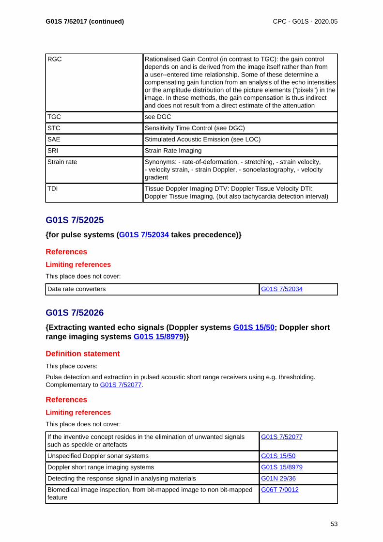
G01S 7/52017 (continued) CPC - G01S - 2020.05
RGC Rationalised Gain Control (in contrast to TGC): the gain controldepends on and is derived from the image itself rather than froma user--entered time relationship. Some of these determine acompensating gain function from an analysis of the echo intensitiesor the amplitude distribution of the picture elements ("pixels") in theimage. In these methods, the gain compensation is thus indirectand does not result from a direct estimate of the attenuation
TGC see DGC
STC Sensitivity Time Control (see DGC)
SAE Stimulated Acoustic Emission (see LOC)
SRI Strain Rate Imaging
Strain rate Synonyms: - rate-of-deformation, - stretching, - strain velocity,- velocity strain, - strain Doppler, - sonoelastography, - velocitygradient
TDI Tissue Doppler Imaging DTV: Doppler Tissue Velocity DTI:Doppler Tissue Imaging, (but also tachycardia detection interval)
G01S 7/52025
{for pulse systems (G01S 7/52034 takes precedence)}
References
Limiting references
This place does not cover:
Data rate converters G01S 7/52034
G01S 7/52026
{Extracting wanted echo signals (Doppler systems G01S 15/50; Doppler shortrange imaging systems G01S 15/8979)}
Definition statement
This place covers:
Pulse detection and extraction in pulsed acoustic short range receivers using e.g. thresholding.Complementary to G01S 7/52077.
References
Limiting references
This place does not cover:
If the inventive concept resides in the elimination of unwanted signalssuch as speckle or artefacts
G01S 7/52077
Unspecified Doppler sonar systems G01S 15/50
Doppler short range imaging systems G01S 15/8979
Detecting the response signal in analysing materials G01N 29/36
Biomedical image inspection, from bit-mapped image to non bit-mappedfeature
G06T 7/0012
53
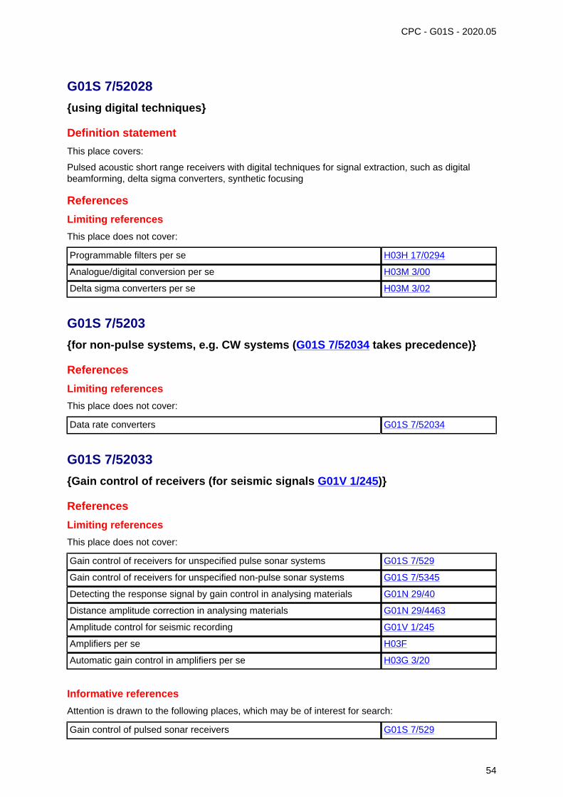
CPC - G01S - 2020.05
G01S 7/52028
{using digital techniques}
Definition statement
This place covers:
Pulsed acoustic short range receivers with digital techniques for signal extraction, such as digitalbeamforming, delta sigma converters, synthetic focusing
References
Limiting references
This place does not cover:
Programmable filters per se H03H 17/0294
Analogue/digital conversion per se H03M 3/00
Delta sigma converters per se H03M 3/02
G01S 7/5203
{for non-pulse systems, e.g. CW systems (G01S 7/52034 takes precedence)}
References
Limiting references
This place does not cover:
Data rate converters G01S 7/52034
G01S 7/52033
{Gain control of receivers (for seismic signals G01V 1/245)}
References
Limiting references
This place does not cover:
Gain control of receivers for unspecified pulse sonar systems G01S 7/529
Gain control of receivers for unspecified non-pulse sonar systems G01S 7/5345
Detecting the response signal by gain control in analysing materials G01N 29/40
Distance amplitude correction in analysing materials G01N 29/4463
Amplitude control for seismic recording G01V 1/245
Amplifiers per se H03F
Automatic gain control in amplifiers per se H03G 3/20
Informative references
Attention is drawn to the following places, which may be of interest for search:
Gain control of pulsed sonar receivers G01S 7/529
54
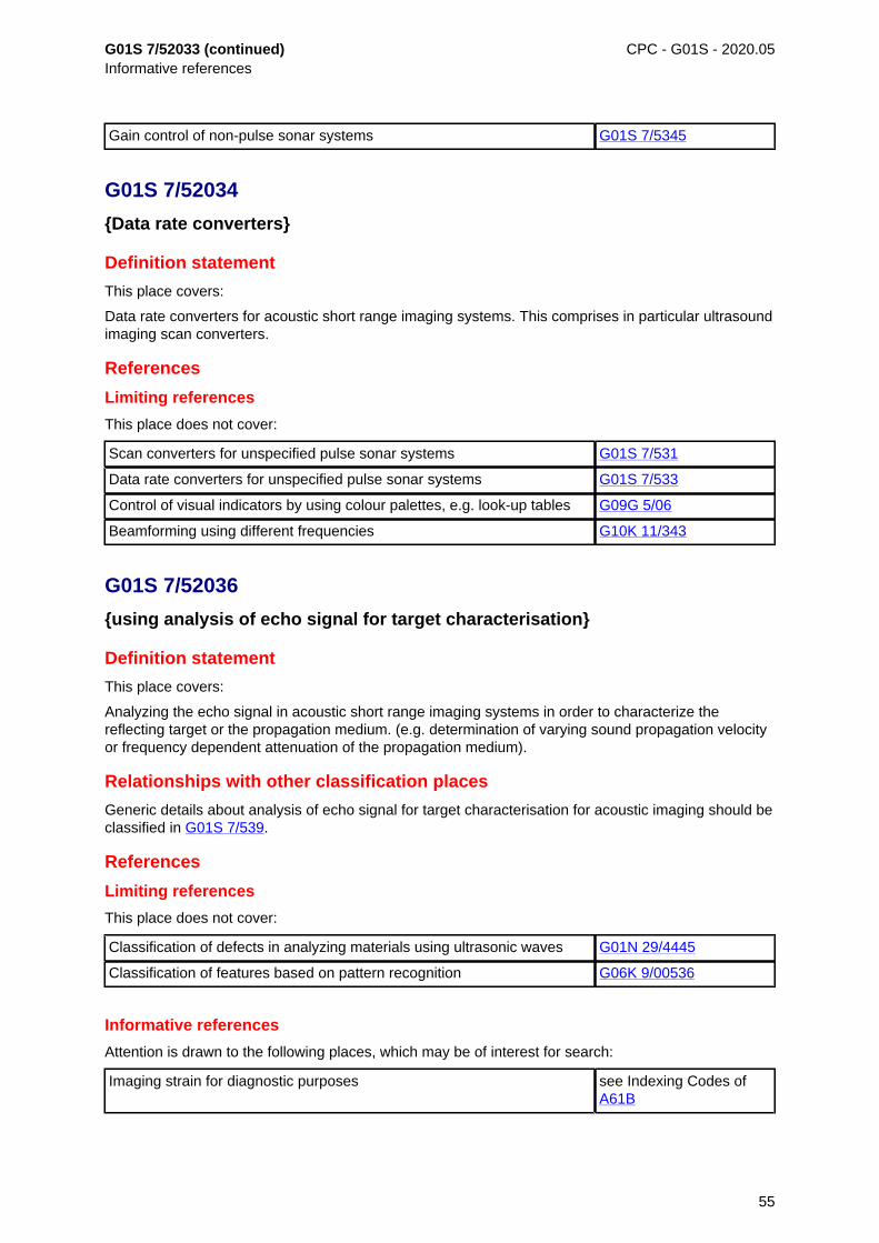
G01S 7/52033 (continued)Informative references
CPC - G01S - 2020.05
Gain control of non-pulse sonar systems G01S 7/5345
G01S 7/52034
{Data rate converters}
Definition statement
This place covers:
Data rate converters for acoustic short range imaging systems. This comprises in particular ultrasoundimaging scan converters.
References
Limiting references
This place does not cover:
Scan converters for unspecified pulse sonar systems G01S 7/531
Data rate converters for unspecified pulse sonar systems G01S 7/533
Control of visual indicators by using colour palettes, e.g. look-up tables G09G 5/06
Beamforming using different frequencies G10K 11/343
G01S 7/52036
{using analysis of echo signal for target characterisation}
Definition statement
This place covers:
Analyzing the echo signal in acoustic short range imaging systems in order to characterize thereflecting target or the propagation medium. (e.g. determination of varying sound propagation velocityor frequency dependent attenuation of the propagation medium).
Relationships with other classification places
Generic details about analysis of echo signal for target characterisation for acoustic imaging should beclassified in G01S 7/539.
References
Limiting references
This place does not cover:
Classification of defects in analyzing materials using ultrasonic waves G01N 29/4445
Classification of features based on pattern recognition G06K 9/00536
Informative references
Attention is drawn to the following places, which may be of interest for search:
Imaging strain for diagnostic purposes see Indexing Codes ofA61B
55
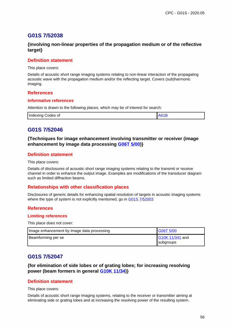
CPC - G01S - 2020.05
G01S 7/52038
{involving non-linear properties of the propagation medium or of the reflectivetarget}
Definition statement
This place covers:
Details of acoustic short range imaging systems relating to non-linear interaction of the propagatingacoustic wave with the propagation medium and/or the reflecting target. Covers (sub)harmonicimaging.
References
Informative references
Attention is drawn to the following places, which may be of interest for search:
Indexing Codes of A61B
G01S 7/52046
{Techniques for image enhancement involving transmitter or receiver (imageenhancement by image data processing G06T 5/00)}
Definition statement
This place covers:
Details of disclosures of acoustic short range imaging systems relating to the transmit or receivechannel in order to enhance the output image. Examples are modifications of the transducer diagramsuch as limited diffraction beams.
Relationships with other classification places
Disclosures of generic details for enhancing spatial resolution of targets in acoustic imaging systemswhere the type of system is not explicitly mentioned, go in G01S 7/52003
References
Limiting references
This place does not cover:
Image enhancement by image data processing G06T 5/00
Beamforming per se G10K 11/341 andsubgroups
G01S 7/52047
{for elimination of side lobes or of grating lobes; for increasing resolvingpower (beam formers in general G10K 11/34)}
Definition statement
This place covers:
Details of acoustic short range imaging systems, relating to the receiver or transmitter aiming ateliminating side or grating lobes and at increasing the resolving power of the resulting system.
56
G01S 7/52047 (continued) CPC - G01S - 2020.05
References
Limiting references
This place does not cover:
Enhancing the spatial resolution in sonar systems G01S 7/52003
Beam formers in general G10K 11/34
Apodisation per se G10K 11/348
G01S 7/52049
{using correction of medium-induced phase aberration}
Definition statement
This place covers:
Details of short range imaging systems relating to the correction of the phase aberration due toinhomogeneous sound velocities in the propagation medium. Also called adaptive imaging.
Glossary of terms
In this place, the following terms or expressions are used with the meaning indicated:
Phase aberration A phased array system assumes a certain acoustic velocityto calculate the focal and steering delays to ensure that alltransmitted or received signals are in phase at the focal point.Inhomogeneous acoustic propagation velocities change theeffective acoustic path length thereby producing a broadening ofthe focal point.
G01S 7/5205
{Means for monitoring or calibrating}
Definition statement
This place covers:
Details of short range imaging systems relating to the monitoring during use of the system orcalibration prior to the use of the system.
References
Limiting references
This place does not cover:
Disclosures of generic details for monitoring and calibrating in acousticimaging systems where the type of system is not explicitly mentioned
G01S 7/52004
Ultrasound phantoms G09B 23/28
Phased array checking or checking devices H01Q 3/267
57
G01S 7/5205 (continued) CPC - G01S - 2020.05
Informative references
Attention is drawn to the following places, which may be of interest for search:
Calibration or testing of ultrasound probes, simulators for testing probes see Indexing Codes ofA61B
Calibration phantoms/bodies for testing ultrasound probes see Indexing Codes ofA61B
G01S 7/52052
{with simulation of echoes}
Definition statement
This place covers:
Details of monitoring and calibrating devices wherein the user has complete control of the reflectedsignal which is used for monitoring or calibration. Covers in particular computer simulation of the echosignal.
References
Limiting references
This place does not cover:
Calibrating or correcting the measurement of coordinates of points G01B 21/04,G01B 21/042,G01B 21/045
G01S 7/52053
{Display arrangements}
References
Limiting references
This place does not cover:
Disclosures of generic details for display arrangements in acousticimaging systems where the type of system is not explicitly mentioned
G01S 7/56
Arrangements for displaying electric variables in general G01R 13/20
G01S 7/52055
{in association with ancillary recording equipment}
Glossary of terms
In this place, the following terms or expressions are used with the meaning indicated:
Ancillary recording equipment supplementary or auxiliary devices, for supplementary recordingduring imaging, such as VCR, data storage, external memory
58
CPC - G01S - 2020.05
G01S 7/52057
{Cathode ray tube displays (cathode ray oscilloscopes in general G01R 13/20)}
Definition statement
This place covers:
Details of short range imaging systems relating to the display of the image.
References
Limiting references
This place does not cover:
Display representation in the analysis of materials (A-, B- or C-Scan) G01N 29/0645
Cathode ray oscilloscopes in general G01R 13/20
Glossary of terms
In this place, the following terms or expressions are used with the meaning indicated:
Cathode ray tube any type of display or screen device. In particular modern LCD,OLED
G01S 7/5206
{Two-dimensional coordinated display of distance and direction; B-scandisplay}
Definition statement
This place covers:
Details of acoustic short range imaging relating to a 2D display.
Glossary of terms
In this place, the following terms or expressions are used with the meaning indicated:
2D two-dimensional
G01S 7/52061
{Plan position indication (PPI display); C-scan display}
Definition statement
This place covers:
Display of constant (or arbitrary) depth images of acoustic short range imaging wherein the imageplane does not correspond to the acquisition plane.
59
G01S 7/52061 (continued) CPC - G01S - 2020.05
References
Informative references
Attention is drawn to the following places, which may be of interest for search:
Imaging apparatus producing slice/tomographic images in user-selectableplanes, not corresponding to acquisition planes. Often combined with 3Dimaging
see Indexing Codes ofA61B
Glossary of terms
In this place, the following terms or expressions are used with the meaning indicated:
C-scan display Constant depth scan;However, exists as well as arbitraryorientation scan
G01S 7/52063
{Sector scan display}
Definition statement
This place covers:
Disclosure relating to the display of parts of an image, such as a particular region of interest, a zoom,a magnifying lens effect.
References
Informative references
Attention is drawn to the following places, which may be of interest for search:
Operator selection of a ROI on an ultrasound image see Indexing Codes ofA61B
Glossary of terms
In this place, the following terms or expressions are used with the meaning indicated:
2D region of interest
Synonyms and Keywords
In patent documents, the following abbreviations are often used:
ROI region of interest
G01S 7/52065
{Compound scan display, e.g. panoramic imaging}
Definition statement
This place covers:
Display of images covering a larger area than what the transducer could cover without movement.Examples are 2D or 3D panoramic imaging, extended field of view imaging.
60
G01S 7/52065 (continued) CPC - G01S - 2020.05
References
Limiting references
This place does not cover:
Acoustic short range imaging systems using a dynamic transducerconfiguration
G01S 15/8934
Spatial or frequency compounding G01S 15/8995
Sound steering by moving the transducer with arcuate movement G10K 11/352,G10K 11/355
Glossary of terms
In this place, the following terms or expressions are used with the meaning indicated:
3D three-dimensional
2D two-dimensional
Synonyms and Keywords
In patent documents, the following abbreviations are often used:
Extended field of view imaging(EFOV, XFOV)
EXtended Field Of View imaging is marketed under at least fivedifferent names - Siescape, - LOGIQView, - FreeStyle extendedimaging, - ApliClear- Panoramic imaging
G01S 7/52066
{Time-position or time-motion displays}
Definition statement
This place covers:
Display of a variable over time in acoustic short range imaging. This covers in particular spectralDoppler imaging, M-mode imaging.
References
Limiting references
This place does not cover:
M-mode imaging for diagnosis see Indexing Codes ofA61B
Measuring blood flow for medical diagnosis A61B 8/06
Detecting organic movements or changes for medical diagnosis A61B 8/08
Informative references
Attention is drawn to the following places, which may be of interest for search:
Indexing Codes of A61B
61
G01S 7/52066 (continued) CPC - G01S - 2020.05
Glossary of terms
In this place, the following terms or expressions are used with the meaning indicated:
M mode (time) Motion mode. B-mode presentation of changing reflectorposition (motion) versus time (used in echocardiography).
G01S 7/52068
{Stereoscopic displays; Three-dimensional displays; Pseudo 3D displays(G01S 15/8993 takes precedence)}
Definition statement
This place covers:
Displays of acoustic short range imaging producing a stereoscopic effect when looked at. Disclosuresrelated exclusively to the displaying of 3D images.
Relationships with other classification places
Acoustic short range imaging systems acquiring and producing 3D data sets which are rendered fordisplaying an image should be classified in G01S 15/8993.
References
Limiting references
This place does not cover:
Three dimensional short range imaging G01S 15/8993
Stereoscopic television systems and details thereof H04N 13/00 andsubgroups
Informative references
Attention is drawn to the following places, which may be of interest for search:
3D imaging for medical diagnosis see Indexing Codes ofA61B
G01S 7/52071
{Multicolour displays; using colour coding; Optimising colour or informationcontent in displays, e.g. parametric imaging}
Definition statement
This place covers:
Disclosures of acoustic short range imaging systems colour coding and mapping information;optimising the colour and/or information display; parametric imaging.
62
G01S 7/52071 (continued) CPC - G01S - 2020.05
References
Limiting references
This place does not cover:
Colour displays in material analysis G01N 29/0609,G01N 29/0618,G01N 29/0627
Control of visual indicators by using colour palettes, e.g. look-up tables G09G 5/06
G01S 7/52073
{Production of cursor lines, markers or indicia by electronic means}
Definition statement
This place covers:
Disclosure of acoustic short range systems overlaying non-alphanumeric information on top of animage.
References
Limiting references
This place does not cover:
Display of alphanumeric information together with an image G01S 7/52074
Informative references
Attention is drawn to the following places, which may be of interest for search:
Indexing Codes of A61B
G01S 7/52074
{Composite displays, e.g. split-screen displays; Combination of multipleimages or of images and alphanumeric tabular information}
References
Informative references
Attention is drawn to the following places, which may be of interest for search:
Indexing Codes of A61B
G01S 7/52076
{Luminous indicators}
Definition statement
This place covers:
Disclosures of any kind of visual indicator in acoustic short range imaging systems, such as LED forinformation or warning.
63
G01S 7/52076 (continued) CPC - G01S - 2020.05
Synonyms and Keywords
In patent documents, the following abbreviations are often used:
LED Light Emitting Device
G01S 7/52077
{with means for elimination of unwanted signals, e.g. noise or interference}
Definition statement
This place covers:
Details of disclosures of acoustic short range imaging systems relating to noise or interferencereduction or elimination: speckle reduction, elimination of artefacts such as aliasing, multiline.Complementary to G01S 7/52026.
References
Limiting references
This place does not cover:
Signal extraction G01S 7/52026
Discriminating between fixed and moving objects or between objectsmoving at different speeds in combined Doppler and pulse-echo shortrange imaging systems
G01S 15/8981
Image enhancement by deblurring, restoration or noise filtering G06T 5/001
G01S 7/521
Constructional features {(constructional features of transducers B06B;mounting transducers G10K 11/00)}
Definition statement
This place covers:
All aspects of mechanical features, of physical layouts involving both transmitter and/or receiver,where these are non-trivial.
References
Limiting references
This place does not cover:
Transducers, singly, in pairs or in arrays, where there is no further non-trivial disclosure of sonar operation
B06B
64
CPC - G01S - 2020.05
G01S 7/524
Transmitters
Definition statement
This place covers:
Schematics, circuit details, circuit diagrams of pulsed sonar transmitters
References
Limiting references
This place does not cover:
Methods or devices for transmitting, conducting or directing sound ingeneral
G10K 11/00
Informative references
Attention is drawn to the following places, which may be of interest for search:
Generating the ultrasonic, sonic or infrasonic wave for investigating oranalysing materials by the use of ultrasonic, sonic or infrasonic waves
G01N 29/34
G01S 7/527
Extracting wanted echo signals {(Doppler systems G01S 15/50)}
Definition statement
This place covers:
Pulse detection and extraction in pulsed acoustic receivers using e.g. thresholding.
References
Limiting references
This place does not cover:
Detecting the response signal in analysing materials G01N 29/36
G01S 7/5273
{using digital techniques}
Definition statement
This place covers:
Pulsed acoustic receivers with digital techniques for signal extraction.
References
Limiting references
This place does not cover:
Analogue/digital conversion per se H03M 3/00
65
CPC - G01S - 2020.05
G01S 7/5276
{using analogue techniques}
Definition statement
This place covers:
Pulsed acoustic receivers using analogue techniques such as analogue sampling, pulse levelthresholds.
G01S 7/529
Gain of receiver varied automatically during pulse-recurrence period {(forseismic signals G01V 1/245)}
References
Limiting references
This place does not cover:
For seismic signals G01V 1/245
Gain control of amplifiers per se H03F
G01S 7/53
Means for transforming coordinates or for evaluating data, e.g. usingcomputers
Definition statement
This place covers:
e.g., converting polar to Cartesian coordinates, details of computer implemented receivers.
G01S 7/531
Scan converters
References
Informative references
Attention is drawn to the following places, which may be of interest for search:
Radar display scan converters G01S 7/298
Ultrasound imaging scan converters G01S 7/52034
66
CPC - G01S - 2020.05
G01S 7/533
Data rate converters
References
Informative references
Attention is drawn to the following places, which may be of interest for search:
Data rate converters for acoustic short range imaging systems G01S 7/52034
G01S 7/534
Details of non-pulse systems {(short-range imaging G01S 7/52017)}
Definition statement
This place covers:
Details including circuit details (circuit diagrams) of sonar using non-pulsed carrier waves.
G01S 7/5345
{Gain control of receivers (for seismic signals G01V 1/245)}
References
Limiting references
This place does not cover:
For seismic signals G01V 1/245
Gain control of amplifiers per se H03F
G01S 7/537
Counter-measures or counter-counter-measures, e.g. jamming, anti-jamming{(in general H04K)}
Definition statement
This place covers:
Means and measures to carry out OR to counter a jamming attack.
References
Limiting references
This place does not cover:
Detection of jamming signals G01S 7/52001
67
CPC - G01S - 2020.05
G01S 7/54
with receivers spaced apart
Definition statement
This place covers:
Receiver arrangements primarily to aid in measuring the distance to the target.
References
Limiting references
This place does not cover:
Receivers spaced apart measuring the bearing of the incoming acousticsignal
G01S 3/802.
G01S 7/56
Display arrangements {(short-range imaging G01S 7/52053)}
Definition statement
This place covers:
All details of sonar displays and the respective data processing.
References
Informative references
Attention is drawn to the following places, which may be of interest for search:
Display systems for short range ultrasonic imaging, G01S 7/52053
Display systems for visualising the interior of objects using sonic,ultrasonic, and infrasonic waves
G01N 29/06
G01S 7/58
for providing variable ranges
Definition statement
This place covers:
User or automatic selection of e.g. different depth ranges.
G01S 7/60
for providing a permanent recording
Definition statement
This place covers:
e.g. arrangements for storing sonar display data for later use.
68
CPC - G01S - 2020.05
G01S 7/62
Cathode-ray tube displays {or other two-dimensional or three-dimensionaldisplays}
Definition statement
This place covers:
Not only details of cathode-ray tube displays (old technique now superseded by newer technologies,e.g. LCD) but details of all kind of displays; such details being e.g. the use of different colours, cursorlines, symbols, plan-position indicators etc.
References
Informative references
Attention is drawn to the following places, which may be of interest for search:
Cathode ray oscilloscopes in general G01R 13/20
G01S 7/6209
{providing display of one measured variable}
Definition statement
This place covers:
e.g. displaying, either graphically or not a single variable, e.g. range to target.
G01S 11/00
Systems for determining distance or velocity not using reflection or reradiation(direction-finders G01S 3/00; position-fixing by co-ordinating two or moredistance determinations G01S 5/00)
Definition statement
This place covers:
Systems for determining distance or velocity not using reflection or reradiation of electromagneticwaves. The exemption does not preclude reflected sunlight, thus cameras operating on imagesreceived from reflected sunlight, are classified here.
References
Informative references
Attention is drawn to the following places, which may be of interest for search:
Direction Finders G01S 3/00
Position fixing G01S 5/00
Special rules of classification
G01S 11/16 takes precedence over G01S 11/02, G01S 11/12 and G01S 11/14.
69
CPC - G01S - 2020.05
G01S 11/02
using radio waves (G01S 19/00 takes precedence)
References
Limiting references
This place does not cover:
Using difference in transit time between electrical and acoustic signals. G01S 11/16
Satellite radio beacon positioning systems including receivers andelements cooperating therewith. Determination of position, velocity orattitude using signals transmitted by such systems.
G01S 19/00
G01S 11/08
using synchronised clocks (synchronisation of electronic clocks G04G 7/02)
References
Informative references
Attention is drawn to the following places, which may be of interest for search:
Synchronisation of electrical clocks G04G 7/02
G01S 11/12
using electromagnetic waves other than radio waves
Definition statement
This place covers:
• Systems for determining distance or velocity not using reflection or reradiation of electromagneticwaves, notably in the optical range, other than radio waves.
• Vehicle anti-collision systems employing optical signals which have neither been reflected norreradiated are classified in this subgroup. Anti-collision systems involving video signals are alsoincluded.
References
Limiting references
This place does not cover:
Using difference in transit time between electrical and acoustic signals G01S 11/16
Measuring distance in line of sight using parallax, i.e. stereo cameras G01C 3/085
Informative references
Attention is drawn to the following places, which may be of interest for search:
Lidar systems specially adapted for anti-collision purposes: G01S 17/93
70
CPC - G01S - 2020.05
G01S 11/14
using ultrasonic, sonic, or infrasonic waves
References
Limiting references
This place does not cover:
Using difference in transit time between electrical and acoustic signals G01S 11/16
G01S 11/16
using difference in transit time between electrical and acoustic signals
Definition statement
This place covers:
Using difference in transit time between electrical and acoustic signals to determine distance andvelocity. Electromagnetic signals, including optical signals are considered as electrical signals.
G01S 13/00
Systems using the reflection or reradiation of radio waves, e.g. radar systems;Analogous systems using reflection or reradiation of waves whose nature orwavelength is irrelevant or unspecified
Definition statement
This place covers:
Systems for detecting the presence of an object, e.g. by reflection or reradiation (G01S 13/74) fromthe object itself, or from a transponder associated with the object, for determining the distance orrelative velocity of an object, for providing a co-ordinated display of the distance and direction of anobject or for obtaining an image thereof; - systems arranged for mounting on a moving craft or vehicleand using the reflection of waves from an extended surface external to the craft, e.g. the surface of theearth, to determine the velocity and direction of motion of the craft relative to the surface.
Relationships with other classification places
Disclosure of analogous systems using reflection or reradiation of acoustic waves go in G01S 15/00;using electromagnetic waves other than radio waves go in G01S 17/00.
References
Application-oriented references
Examples of places where the subject matter of this place is covered when specially adapted, used fora particular purpose, or incorporated in a larger system:
Measuring liquid levels G01F 23/284
Informative references
Attention is drawn to the following places, which may be of interest for search:
Systems for determining the direction of an object by means notemploying reflection or reradiation, which are covered by groups
G01S 1/00, G01S 3/00
71
G01S 13/00 (continued)Informative references
CPC - G01S - 2020.05
Systems for determining distance or velocity of an object by means notemploying reflection or reradiation, which are covered by group
G01S 11/00
Using forward scattering and measuring material property G01N
Special rules of classification
Details of disclosures of systems which conceptually form a technically important or technically non-trivial part of a disclosure should be classified in G01S 7/02, as well as the appropriate system groupin G01S 13/00, especially if these details form a significant part of the disclosure, and do not concernwell-known and widely retrievable subject-matter.
where a disclosure specifies alternative methods of measuring distance, for example, both time offlight of a transmitted and received radio pulse, as well as a difference measured in a transmittedand reflected continuous wave radio signal, and if these are described in detail, then the disclosure isclassified in both G01S 13/10 and G01S 13/32.
G01S 13/003
{Bistatic radar systems; Multistatic radar systems}
Definition statement
This place covers:
Radar systems having a transmitting antenna which is dislocated from the receiving antenna; radarsystems without a transmitter antenna that use illuminators of opportunity, e.g. ambient radio signals,satellite signals, TV-station signals.
References
Limiting references
This place does not cover:
Monostatic radar systems having a separate transmit and receiveantenna, as typically used in FMCW radar.
G01S 13/34
Informative references
Attention is drawn to the following places, which may be of interest for search:
Combination of radar systems G01S 13/87
G01S 13/0209
{Systems with very large relative bandwidth, i.e. larger than 10 %, e.g.baseband, pulse, carrier-free, ultrawideband}
Synonyms and Keywords
In patent documents, the following abbreviations are often used:
UWB Ultra Wideband
72
CPC - G01S - 2020.05
G01S 13/0218
{Very long range radars, e.g. surface wave radar, over-the-horizon orionospheric propagation systems (for meteorological use G01S 13/95)}
Synonyms and Keywords
In patent documents, the following abbreviations are often used:
OTH Over-The-Horizon
G01S 13/04
Systems determining the presence of a target (based on relative movement oftarget G01S 13/56)
Definition statement
This place covers:
Systems where only the detection of the existence or not of a signal reflected from a target to thereceiver is important.
Special rules of classification
Systems based on relative movement of the target, see G01S 13/56.
G01S 13/06
Systems determining position data of a target
Definition statement
This place covers:
Systems where an own position at a measuring point is unknown within a given reference system, andis measured using active radio rangefinding, as well as systems where position of a target relative toa measuring point is determined using non-defined measurements of a signal reflected from the targetand received at that measuring point.
G01S 13/08
Systems for measuring distance only (indirect measurement G01S 13/46)
Definition statement
This place covers:
Systems where a disclosure specifies alternative methods of measuring distance, for example,both time of flight of a transmitted and received radio pulse, as well as a difference measured in atransmitted and reflected continuous wave radio signal, and if these are described in detail, then thedisclosure is classified in both G01S 13/10 and G01S 13/32.
References
Limiting references
This place does not cover:
Indirect measurement G01S 13/46
73

CPC - G01S - 2020.05
G01S 13/103
{particularities of the measurement of the distance (G01S 13/12, G01S 13/14,G01S 13/16, G01S 13/18 and G01S 13/20 take precedence)}
Definition statement
This place covers:
Particularities relating to measurement method involving transmission and reception; details as suchare put in G01S 7/02.
Special rules of classification
G01S 13/14, G01S 13/12, G01S 13/16, G01S 13/20, and G01S 13/18 take precedence.
G01S 13/106
{using transmission of pulses having some particular characteristics(G01S 13/12, G01S 13/22, G01S 13/24, G01S 13/26, G01S 13/28 and G01S 13/30take precedence)}
Special rules of classification
G01S 13/12, G01S 13/22, G01S 13/24, G01S 13/26, G01S 13/28 and G01S 13/30 take precedence
G01S 13/18
wherein range gates are used
Synonyms and Keywords
In patent documents, the following words/expressions are often used as synonyms:
• "range gate", "range bin" and "range cell"
G01S 13/38
wherein more than one modulation frequency is used
Definition statement
This place covers:
Systems using the simultaneous transmission of dual- or multi-frequency signals.
G01S 13/42
Simultaneous measurement of distance and other co-ordinates (indirectmeasurement G01S 13/46)
Definition statement
This place covers:
Systems using other coordinates that include Cartesian or polar spatial coordinates of target
74
G01S 13/42 (continued) CPC - G01S - 2020.05
References
Limiting references
This place does not cover:
Bearing and direction finders per se G01S 3/02
Indirect measurement G01S 13/46
G01S 13/44
Monopulse radar, i.e. simultaneous lobing
References
Informative references
Attention is drawn to the following places, which may be of interest for search:
Monopulse in direction finding G01S 3/32
G01S 13/4409
{HF sub-systems particularly adapted therefor, e.g. circuits for signalcombination (multi-lobing aerials or aerial systems H01Q 25/00)}
References
Informative references
Attention is drawn to the following places, which may be of interest for search:
Waveguide couplers H01P 5/00
Multilobing aerials or aerial systems H01Q 25/00
G01S 13/46
Indirect determination of position data
Definition statement
This place covers:
Techniques not involving the measurement of the time of flight of the measurement signal betweentransmitter and receiver.
G01S 13/48
using multiple beams at emission or reception
References
Informative references
Attention is drawn to the following places, which may be of interest for search:
Stacked beam radar systems G01S 13/424
75
CPC - G01S - 2020.05
G01S 13/524
based upon the phase or frequency shift resulting from movement of objects,with reference to the transmitted signals, e.g. coherent MTI (coherent receiversG01S 7/288)
References
Limiting references
This place does not cover:
This subgroup does not cover clutter analysis for stationary targets:
Coherent receivers G01S 7/288
Glossary of terms
In this place, the following terms or expressions are used with the meaning indicated:
MTI moving target indicator
G01S 13/5244
{Adaptive clutter cancellation (specially adapted for airborne MTI,G01S 13/5242)}
References
Limiting references
This place does not cover:
Clutter analysis for stationary targets:
Discriminating targets with respect to background clutter G01S 7/414
Specially adapted for MTI G01S 13/5242
G01S 13/5265
{IF cancellers, e.g. TACCAR systems}
Glossary of terms
In this place, the following terms or expressions are used with the meaning indicated:
TACCAR Time-Averaged Clutter-Coherent Airborne Radar
76
CPC - G01S - 2020.05
G01S 13/58
Velocity or trajectory determination systems; Sense-of-movementdetermination systems {(systems applied to the controlling of trafficG01S 13/92)}
Definition statement
This place covers:
Systems that measure properties of the reflected signal which contain information allowing the velocityof a moving target to be derived, where the moving target has a surface which causes reflection of theimpinging radio measurement beam e.g. solid objects, particles suspended in a moving fluid: Note: thevelocity of the moving fluid may be inferred from the measured velocity of the particles.
G01S 13/75
using transponders powered from received waves, e.g. using passivetransponders {, or using passive reflectors}
Definition statement
This place covers:
Transponders which are operable in the context of determining position, range, or velocity.
Relationships with other classification places
Record carriers comprising integrated circuit chips: G06K 19/07
References
Limiting references
This place does not cover:
Transponders that are used for the mere exchange of data. G06K 7/00
Synonyms and Keywords
In patent documents, the following abbreviations are often used:
RFID Radio Frequency Identification
G01S 13/756
{using a signal generator for modifying the reflectivity of the reflector(G01S 13/758 takes precedence)}
Synonyms and Keywords
In patent documents, the following words/expressions are often used as synonyms:
• "modifying reflectivity for data transmission" and "backscatter modulation"
77
CPC - G01S - 2020.05
G01S 13/84
for distance determination by phase measurement
References
Informative references
Attention is drawn to the following places, which may be of interest for search:
Phase measurement using reflection G01S 13/36
G01S 13/87
Combinations of radar systems, e.g. primary radar and secondary radar
References
Informative references
Attention is drawn to the following places, which may be of interest for search:
Transmission of data between radar systems G01S 7/003
Special rules of classification
This subgroup relates to combination of radar systems, meaning that separate, independentlyoperating radar systems are combined into one overall system, in particular by combiningmeasurement data. Radar systems that for example comprise two transmitters are not considered acombination of radar systems.
G01S 13/878
{Combination of several spaced transmitters or receivers of known locationfor determining the position of a transponder or a reflector (G01S 13/874 takesprecedence)}
References
Informative references
Attention is drawn to the following places, which may be of interest for search:
Determining absolute distances from a plurality of spaced points of knownlocation
G01S 5/14
G01S 13/885
{for ground probing (prospecting or detecting using electromagnetic wavesG01V 3/12)}
Synonyms and Keywords
In patent documents, the following abbreviations are often used:
GPR ground penetrating radar
78
CPC - G01S - 2020.05
G01S 13/887
{for detection of concealed objects, e.g. contraband or weapons}
References
Informative references
Attention is drawn to the following places, which may be of interest for search:
Prospecting using millimetre waves G01V 8/005
G01S 13/9023
{combined with interferometric techniques}
References
Informative references
Attention is drawn to the following places, which may be of interest for search:
Phase comparisons monopulse G01S 13/4454
Monopulse hyvrid systems, e.g. conopulse G01S 13/4481
G01S 13/9029
{specially adapted for moving target detection within a single SAR image orwithin multiple SAR images taken at the same time}
References
Informative references
Attention is drawn to the following places, which may be of interest for search:
Discriminating between fixed and moving objects or between objectsmoving at different speeds
G01S 13/52
G01S 13/91
for traffic control (G01S 13/93 takes precedence)
Relationships with other classification places
Traffic control system per se: G08G.
References
Limiting references
This place does not cover:
For anti-collision purposes G01S 13/93
79
G01S 13/91 (continued) CPC - G01S - 2020.05
Informative references
Attention is drawn to the following places, which may be of interest for search:
Monitoring traffic from ground station G08G 5/0082
G01S 13/92
for velocity measurement
References
Informative references
Attention is drawn to the following places, which may be of interest for search:
Traffic control systems measuring speed G08G 1/052
G01S 13/933
of aircraft or spacecraft
Synonyms and Keywords
In patent documents, the following abbreviations are often used:
TCAS Traffic Collision Avoidance System
G01S 13/95
for meteorological use
Relationships with other classification places
Meteorology per se: G01W 1/00
G01S 15/00
Systems using the reflection or reradiation of acoustic waves, e.g. sonarsystems
Definition statement
This place covers:
Systems for detecting presence, distance, position, movement and velocity of objects in spaceusing the reflection of propagating acoustic waves or re-radiation (G01S 15/74) of acoustic waves.Systems for acoustic imaging are also covered, but are divided between long range (far field systems):G01S 15/89, and short range imaging and echography G01S 15/8906; this short range imaging areais dealt with in a separate definition statement.
Relationships with other classification places
Disclosures of generic systems for detecting presence, distance, position, movement and velocity ofobjects in space using the reflection of propagating waves or re-radiation of waves where the type ofwaves are not explicitly mentioned, go in G01S 13/00; but if these systems include features which areidentifiable as relating to acoustic systems, then a class is also given in G01S 15/00.
80
G01S 15/00 (continued) CPC - G01S - 2020.05
References
Application-oriented references
Examples of places where the subject matter of this place is covered when specially adapted, used fora particular purpose, or incorporated in a larger system:
Acoustic well logging G01V 1/40
Towed fish G10K, G01V
Informative references
Attention is drawn to the following places, which may be of interest for search:
Seismic prospecting, acoustic detecting G01V 1/00- G01V 1/37
Acoustic beamformers G10K
Special rules of classification
Details of disclosures of systems which conceptually form a technically important or technically non-trivial part of a disclosure should be classified in G01S 7/52, as well as the appropriate system groupin G01S 15/00, especially if these details form a significant part of the disclosure, and do not concernwell-known and widely retrievable subject-matter.
where a disclosure specifies alternative methods of measuring distance, for example, both time offlight of a transmitted and received sound pulse, as well as a difference measured in a transmitted andreflected continuous wave acoustic signal, and if these are described in detail, then the disclosure isclassified in both G01S 15/10 and G01S 15/32.
Glossary of terms
In this place, the following terms or expressions are used with the meaning indicated:
2D two dimensional
Synonyms and Keywords
In patent documents the word "sonar" is often used with the meaning "passive acoustic receiving/listening system".
Therefore the keyword "sonar" should be used with caution.
G01S 15/04
Systems determining presence of a target
Definition statement
This place covers:
Systems where only the detection of the existence or not of a signal reflected from a target to thereceiver is important.
81
CPC - G01S - 2020.05
G01S 15/06
Systems determining the position data of a target
Definition statement
This place covers:
Systems where an own position at a measuring point is unknown within a given reference system,and is measured using active acoustic rangefinding, are put here; as well as systems where positionof a target relative to a measuring point is determined using non-defined measurements of a signalreflected from the target and received at that measuring point.
G01S 15/08
Systems for measuring distance only (indirect measurement G01S 15/46)
Definition statement
This place covers:
Where a disclosure specifies alternative methods of measuring distance, for example, both time offlight of a transmitted and received acoustic pulse, as well as a difference measured in a transmittedand reflected continuous wave acoustic signal, and if these are described in detail, then the disclosureis classified in both G01S 15/10 and G01S 15/32.
References
Limiting references
This place does not cover:
Indirect measurement G01S 15/46
G01S 15/101
{Particularities of the measurement of distance (G01S 15/12, G01S 15/14, andG01S 15/18 take precedence)}
Definition statement
This place covers:
Particularities relating to measurement method involving transmission and reception; details as suchare put in G01S 7/52.
G01S 15/42
Simultaneous measurement of distance and other co-ordinates (indirectmeasurement G01S 15/46)
Definition statement
This place covers:
Other coordinates include Cartesian or polar spatial coordinates of target.
82
G01S 15/42 (continued) CPC - G01S - 2020.05
References
Limiting references
This place does not cover:
Bearing and direction finders per se G01S 3/80
G01S 15/46
Indirect determination of position data
Definition statement
This place covers:
Techniques not involving the measurement of the time of flight of the measurement signal betweentransmitter and receiver.
G01S 15/58
Velocity or trajectory determination systems; Sense-of-movementdetermination systems {(velocity measurement in imaging systemsG01S 15/8979)}
Definition statement
This place covers:
Measuring properties of the reflected signal which contain information allowing the velocity of a movingtarget to be derived, where the moving target has a surface which causes reflection of the impingingacoustic measurement beam e.g. solid objects, particles suspended in a moving fluid: Note: thevelocity of the moving fluid may be inferred from the measured velocity of the particles.
Special rules of classification
Determining velocities by acoustic means when propagation effects are not relevant, e.g. acousticallymeasuring the velocity of moving fluids per se, G01P 5/24, acoustically measuring fluid flow per se;G01F 1/66, measuring blood flow per se A61B 8/00.
G01S 15/74
Systems using reradiation of acoustic waves, e.g. IFF, i.e. identification offriend or foe
References
Informative references
Attention is drawn to the following places, which may be of interest for search:
Teaching or practice apparatus for gun-arming or gun-laying usingreflecting targets or active targets
F41G 3/26
83
CPC - G01S - 2020.05
G01S 15/885
{Meteorological systems}
References
Informative references
Attention is drawn to the following places, which may be of interest for search:
Measuring wind speed G01P 5/24
G01S 15/8906
{Short-range imaging systems; Acoustic microscope systems using pulse-echo techniques}
Definition statement
This place covers:
Systems for short range imaging using reflection of propagating acoustic waves, in particular medicalultrasound imaging systems.
Relationships with other classification places
Disclosures which concern the functioning of the full system should go in G01S 15/8906.
References
Limiting references
This place does not cover:
Details of systems which form an important or technically non-trivial partof a disclosure of a system
G01S 7/52017
Medical diagnosis by ultrasounds A61B 8/00
Generating or transmitting mechanical vibrations of ultrasonic frequency B06B
Thickness measurement by ultrasonic waves G01B 17/02
Flow measurements by ultrasonic waves G01F 1/66
Measuring or indicating of ultrasonic, sonic or infrasonic waves in general G01H
Analysing solids by imaging using ultrasonic waves G01N 29/06
Seismic or acoustic prospecting or detecting G01V 1/00
Obtaining records by techniques analogous to photography usingultrasonic waves
G03B 42/06
Models for scanning techniques in medical ultrasonics G09B 23/286
Wiring or connecting of acoustic transducers per se G10K 11/004
Sound-focusing or directing, e.g. scanning G10K 11/26 andsubgroups
Informative references
Attention is drawn to the following places, which may be of interest for search:
Medical diagnostic ultrasound applications A61B 8/00
84
G01S 15/8906 (continued)Informative references
CPC - G01S - 2020.05
Transducers per se B06B1/01
Investigating solids using ultrasound G01N 29/00
Image processing per se G06T
Beamforming of ultrasound waves G10K 11/34
Special rules of classification
For systems transmitting data to a remote station G01S 7/003 should be given
Details of disclosures of systems which conceptually form a technically important or technically non-trivial part of a disclosure should be classified in G01S 7/52017, as well as the appropriate systemsubgroup in G01S 15/8906, especially if these details form a significant part of the disclosure, and donot concern well-known and widely retrievable subject-matter.
Synonyms and Keywords
In patent documents, the following abbreviations are often used:
ARFI Acoustic Radiation Force Impulse:uses brief, high energy focusedacoustic pulses to generate radiation force in remote locations intissue and conventional diagnostic ultrasound methods to detectthe resulting tissue displacements in order to provide informationabout mechanical properties of tissue (e.g. shear wave modulus)
ASAE Acoustically Stimulated Acoustic Emission: A contrastphenomenon which involves microbubble destruction and enablesimaging of small vessel flow (also LOC: loss of correlation;Transient disruption; SAE: Stimulated Acoustic Emission)
CDE Colour Doppler Energy, synonym of Colour Power Doppler
CPA Colour Power Angio, synonym to Colour Power Doppler
DGC Depth Gain Compensation, synonyms: AGC: Automated GainCompensation; TGC: Time gain compensation; STC: Sensitivitytime control; FGC: Focal Gain Compensation; other forms ofcompensation: LGC: lateral gain compensation (azimuth);axialgain compensation ; EGC: elevation gain compensation- inultrasonic flaw detection also called DAC: distance amplitudecorrection
XFOV eXtended Field Of View (see EFOV)
EFOV Extended Field Of View imaging is marketed under at least fivedifferent names (see G01S 7/52065 ) - Siescape, - LOGIQView, -FreeStyle extended imaging, - ApliClear- Panoramic imaging
LOC Loss of correlation: Contrast agent imaging method. A high MIpulse destroys the microbubbles of the contrast agent, whichleads to a sudden increase of the scattered signal. Later, weakerpulses image the region. Synonyms: - SEA: stimulated acousticemission, - ASEA: Acoustically Stimulated Acoustic Emission -intermittent imaging - sonoscintigraphy, - flash echo imaging -flashing - transient disruption- transient imaging
MI Mechanical Index: An indicator of nonthermal mechanism activity;equal to the peak rarefactional pressure divided by the square rootof the center frequency of the pulse bandwidth.
MLA Multi-Line-Acquisition (a special case would be: Fat BeamTransmission)
85
G01S 15/8906 (continued) CPC - G01S - 2020.05
MPR (also called I-scan:inclined)
Multi-Planar-Reslicingarbitrary cut plane in a 3D ultrasonic imagingdata block
RGC Rationalised Gain Control (in contrast to TGC): the gain controldepends on and is derived from the image itself rather than froma user--entered time relationship. Some of these determine acompensating gain function from an analysis of the echo intensitiesor the amplitude distribution of the picture elements ("pixels") in theimage. In these methods, the gain compensation is thus indirectand does not result from a direct estimate of the attenuation
TGC see DGC
STC Sensitivity Time Control (see DGC)
SAE Stimulated Acoustic Emission (see LOC)
SRI Strain Rate Imaging
Strain rate Synonyms: - rate-of-deformation, - stretching, - strain velocity,- velocity strain, - strain Doppler, - sonoelastography, - velocitygradient
TDI Tissue Doppler Imaging DTV: Doppler Tissue Velocity DTI:Doppler Tissue Imaging, (but also tachycardia detection interval)
G01S 15/8909
{using a static transducer configuration (sound-focusing or directing per seG10K 11/26)}
Definition statement
This place covers:
Acoustic short range imaging systems, in particular medical ultrasound imaging systems, wherein thefact that the imaging transducers are static is essential.
References
Limiting references
This place does not cover:
Constructional aspects of transducers B06B 1/0607, B06B 1/085
Piezoelectric probes for analysing materials G01N 29/2437
Analysing materials using electronic focusing, e.g. phased arrays G01N 29/262
Sound-focusing or directing per se G10K 11/26
Aspects related to the shape of the transducer G10K 11/32
Phased arrays and beamforming per se G10K 11/34
Informative references
Attention is drawn to the following places, which may be of interest for search:
Transducers per se B06B 1/06
Sound-focusing using acoustic lenses G10K 11/28
86
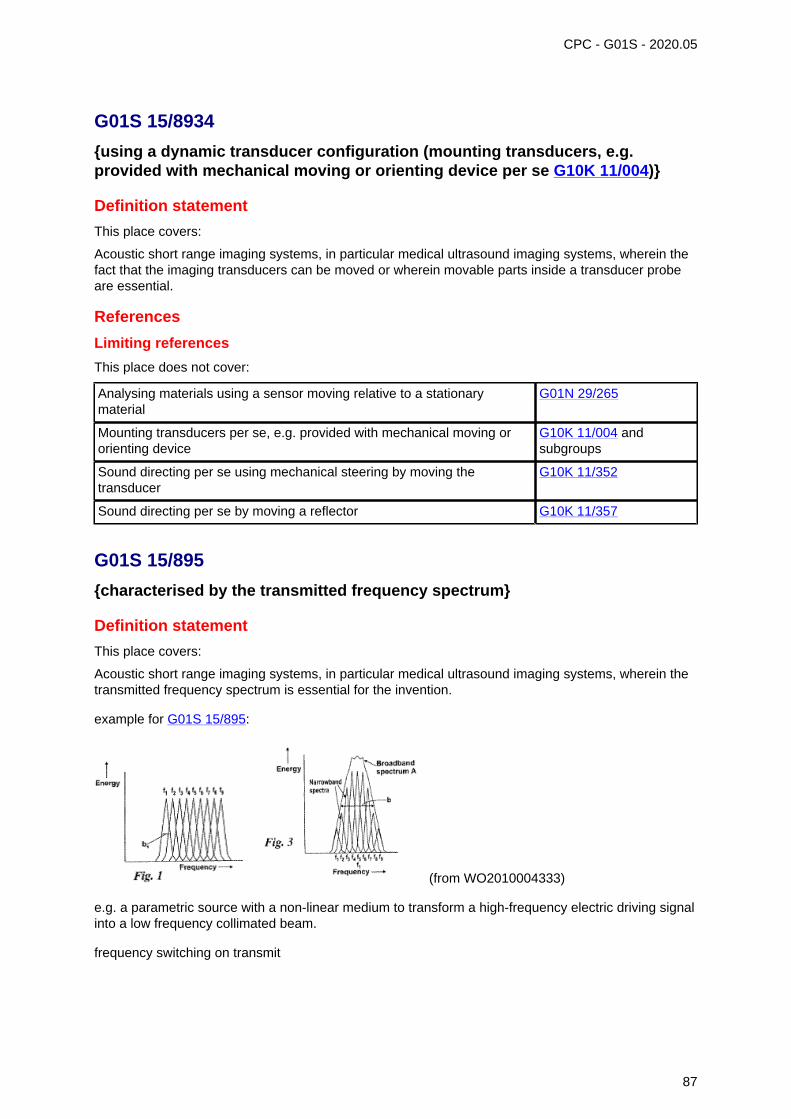
CPC - G01S - 2020.05
G01S 15/8934
{using a dynamic transducer configuration (mounting transducers, e.g.provided with mechanical moving or orienting device per se G10K 11/004)}
Definition statement
This place covers:
Acoustic short range imaging systems, in particular medical ultrasound imaging systems, wherein thefact that the imaging transducers can be moved or wherein movable parts inside a transducer probeare essential.
References
Limiting references
This place does not cover:
Analysing materials using a sensor moving relative to a stationarymaterial
G01N 29/265
Mounting transducers per se, e.g. provided with mechanical moving ororienting device
G10K 11/004 andsubgroups
Sound directing per se using mechanical steering by moving thetransducer
G10K 11/352
Sound directing per se by moving a reflector G10K 11/357
G01S 15/895
{characterised by the transmitted frequency spectrum}
Definition statement
This place covers:
Acoustic short range imaging systems, in particular medical ultrasound imaging systems, wherein thetransmitted frequency spectrum is essential for the invention.
example for G01S 15/895:
(from WO2010004333)
e.g. a parametric source with a non-linear medium to transform a high-frequency electric driving signalinto a low frequency collimated beam.
frequency switching on transmit
87
G01S 15/895 (continued) CPC - G01S - 2020.05
References
Limiting references
This place does not cover:
Different forms of pulses G01S 15/10 andsubgroups
Investigating or analysing materials generating the ultrasonic waves withfrequency characteristics, e.g. single frequency, chirps
G01N 29/348
Special rules of classification
High frequency, i.e. above 20 MHz, ultrasound imaging should be classified here
G01S 15/8952 should be given for several Dirac peaks in the frequency spectrum
G01S 15/8954 should be given in case of a spread spectrum and of chirps. However, only when usingultrashort (and hence broadband) pulses
In case the two possibilities, G01S 15/8952 and G01S 15/8954, are relevant the main subgroupshould be given, not both sub-groups
G01S 15/8959
{using coded signals for correlation purposes}
Definition statement
This place covers:
Acoustic short range imaging systems, in particular medical ultrasound imaging systems, using codedsignals for pulse compression (coding by e.g. Golay codes, Barker codes or chirps), differentiatingmultiple transmit beams using coded signals.
Synonyms and Keywords
In patent documents, the following abbreviations are often used:
PED Pulse Elongation and Deconvolution
G01S 15/8965
{using acousto-optical or acousto-electronic conversion techniques}
Definition statement
This place covers:
Acoustic short range imaging systems, in particular medical ultrasound imaging systems, with anoptical-acoustic transducer structure using an absorbed pump light pulse in the transducer probe togenerate a sound pulse;
Systems comprising two acoustic arrays with circuitry between them in order to work after the mannerof a lens; Interferometric detection of reflected ultrasound waves for imaging purposes.
88
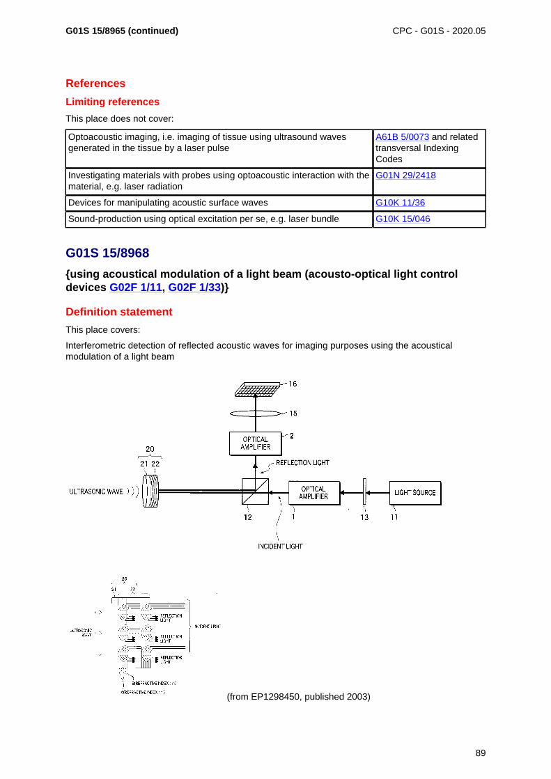
G01S 15/8965 (continued) CPC - G01S - 2020.05
References
Limiting references
This place does not cover:
Optoacoustic imaging, i.e. imaging of tissue using ultrasound wavesgenerated in the tissue by a laser pulse
A61B 5/0073 and relatedtransversal IndexingCodes
Investigating materials with probes using optoacoustic interaction with thematerial, e.g. laser radiation
G01N 29/2418
Devices for manipulating acoustic surface waves G10K 11/36
Sound-production using optical excitation per se, e.g. laser bundle G10K 15/046
G01S 15/8968
{using acoustical modulation of a light beam (acousto-optical light controldevices G02F 1/11, G02F 1/33)}
Definition statement
This place covers:
Interferometric detection of reflected acoustic waves for imaging purposes using the acousticalmodulation of a light beam
(from EP1298450, published 2003)
89
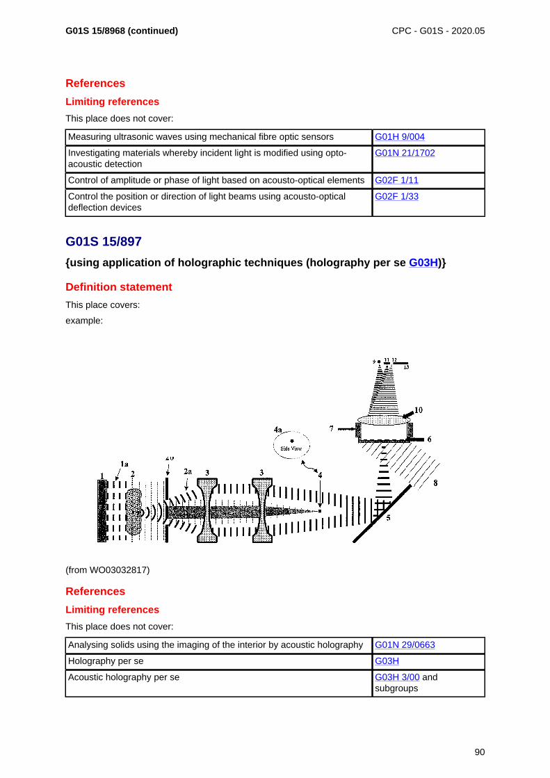
G01S 15/8968 (continued) CPC - G01S - 2020.05
References
Limiting references
This place does not cover:
Measuring ultrasonic waves using mechanical fibre optic sensors G01H 9/004
Investigating materials whereby incident light is modified using opto-acoustic detection
G01N 21/1702
Control of amplitude or phase of light based on acousto-optical elements G02F 1/11
Control the position or direction of light beams using acousto-opticaldeflection devices
G02F 1/33
G01S 15/897
{using application of holographic techniques (holography per se G03H)}
Definition statement
This place covers:
example:
(from WO03032817)
References
Limiting references
This place does not cover:
Analysing solids using the imaging of the interior by acoustic holography G01N 29/0663
Holography per se G03H
Acoustic holography per se G03H 3/00 andsubgroups
90
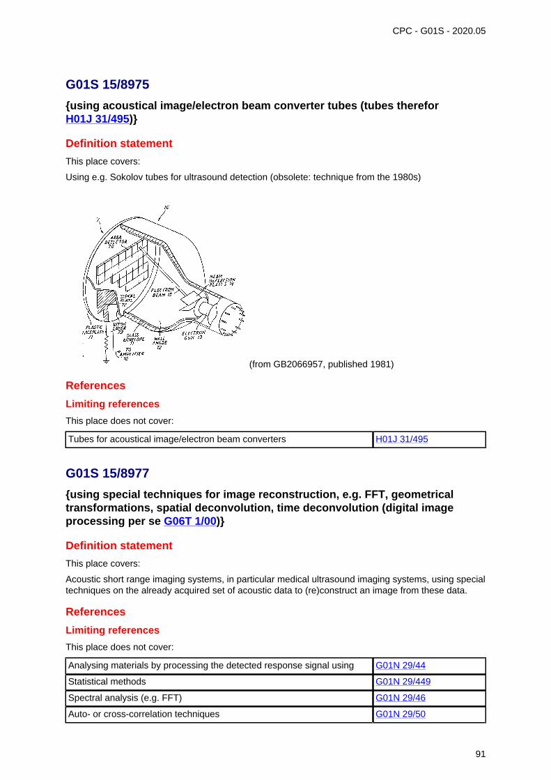
CPC - G01S - 2020.05
G01S 15/8975
{using acoustical image/electron beam converter tubes (tubes thereforH01J 31/495)}
Definition statement
This place covers:
Using e.g. Sokolov tubes for ultrasound detection (obsolete: technique from the 1980s)
(from GB2066957, published 1981)
References
Limiting references
This place does not cover:
Tubes for acoustical image/electron beam converters H01J 31/495
G01S 15/8977
{using special techniques for image reconstruction, e.g. FFT, geometricaltransformations, spatial deconvolution, time deconvolution (digital imageprocessing per se G06T 1/00)}
Definition statement
This place covers:
Acoustic short range imaging systems, in particular medical ultrasound imaging systems, using specialtechniques on the already acquired set of acoustic data to (re)construct an image from these data.
References
Limiting references
This place does not cover:
Analysing materials by processing the detected response signal using G01N 29/44
Statistical methods G01N 29/449
Spectral analysis (e.g. FFT) G01N 29/46
Auto- or cross-correlation techniques G01N 29/50
91
G01S 15/8977 (continued)Limiting references
CPC - G01S - 2020.05
Digital image processing per se G06T 1/00
G01S 15/8979
{Combined Doppler and pulse-echo imaging systems}
Definition statement
This place covers:
Acoustic short range imaging systems, in particular medical ultrasound imaging systems, usingduplex imaging, i.e. colour coded flow velocity information extracted using Doppler signals overlaidas parametric information on B-mode images. General Doppler system should be classified inG01S 15/8979
References
Limiting references
This place does not cover:
Systems relating to spectral Doppler only G01S 7/52066
Determining the velocity vector for example of the blood flow G01S 15/588
Measuring blood flow for medical diagnosis A61B 8/06
Diagnostic techniques involving Doppler signals A61B 8/488
Blood flow in combination with B-scan for diagnosis A61B 8/5246
Measuring of volume flow using ultrasound G01F 1/663
Measuring speed of fluids in general G01P 5/00
Informative references
Attention is drawn to the following places, which may be of interest for search:
For the principle underlying wall filters (i.e. G01S 15/8981) G01S 13/5244
Determining the velocity vector G01S 15/588
G01S 15/899
{Combination of imaging systems with ancillary equipment}
Definition statement
This place covers:
Acoustic short range imaging systems, in particular medical ultrasound imaging systems, wherein theancillary equipment has a direct and important influence on the acoustic imaging itself.
References
Limiting references
This place does not cover:
Measuring for diagnostic purposes A61B 5/00
Ultrasound lithotripsy A61B 17/22004,A61B 17/225
92
G01S 15/899 (continued) CPC - G01S - 2020.05
Informative references
Attention is drawn to the following places, which may be of interest for search:
ICT specially adapted for handling or processing of medical images G16H 30/00
Glossary of terms
In this place, the following terms or expressions are used with the meaning indicated:
Ancillary equipment supplementary or auxiliary devices, for supplementary sensing ormonitoring during imaging, such as temperature sensors, coolingsystems, tracking systems, docking units, ECG systems, highintensity focused ultrasound probes used for or during imaging, orcombinations thereof
Synonyms and Keywords
In patent documents, the following abbreviations are often used:
ECG Electrocardiogram
PPG photoplenthysmography, e.g. a pulse oximeter
G01S 15/8993
{Three dimensional imaging systems}
Definition statement
This place covers:
Acoustic short range imaging systems, in particular medical ultrasound imaging systems, using theacquisition of a three-dimensional set of data to produce via per se well-known rendering techniques athree-dimensional image.
References
Limiting references
This place does not cover:
Three-dimensional stereoscopic images G01S 7/52068
3D image rendering G06T 15/00
Ray tracing per se G06T 15/06
Volume rendering per se G06T 15/08
3D modelling, e.g. data description of 3D objects G06T 17/00
Manipulating 3D images G06T 19/00
Informative references
Attention is drawn to the following places, which may be of interest for search:
Diagnosis using ultrasound 3D A61B 8/466
93
G01S 15/8993 (continued) CPC - G01S - 2020.05
Synonyms and Keywords
In patent documents, the following abbreviations are often used:
3D three-dimensional
G01S 15/8995
{Combining images from different aspect angles, e.g. spatial compounding}
References
Limiting references
This place does not cover:
Image enhancement per se using more than one image, e.g. averaging,subtraction
G06T 5/50
Determination of transform parameters for the alignment of images, i.e.image registration
G06T 7/30
Glossary of terms
In this place, the following terms or expressions are used with the meaning indicated:
Spatial Compounding Averaging of frames that view anatomy from different imagingangles.
G01S 17/00
Systems using the reflection or reradiation of electromagnetic waves otherthan radio waves, e.g. lidar systems
Definition statement
This place covers:
This main group covers systems for detecting presence, distance, position, movement and velocityof objects in space using the reflection of propagating electromagnetic waves or re-radiation(G01S 17/74) of electromagnetic waves where the wavelength of the electromagnetic waves is shorterthan the range of electromagnetic wavelengths including millimetric waves.
Relationships with other classification places
Disclosures of generic systems for detecting presence, distance, position, movement and velocityof objects in space using the reflection of propagating electromagnetic waves or re-radiationof electromagnetic waves where the range of wavelengths are not explicitly mentioned, go inG01S 13/00; but if these systems include features which are identifiable as relating to optical systems,then a class is also given in G01S 17/00.
References
Informative references
Attention is drawn to the following places, which may be of interest for search:
Measuring linear dimensions, e.g. length, thickness, and distancesbetween spaced objects
G01B
94
G01S 17/00 (continued)Informative references
CPC - G01S - 2020.05
Measuring distances, levels, bearings; surveying; navigation G01C
Photogrammetry or videogrammetry G01C 11/00
Measuring light per se G01J
Investigating materials by optical radiation, microwaves or acoustic waves G01N
Measuring linear or angular speed, indicating presence, absence, ordirection of movement
G01P
Detecting masses or objects by methods not involving reflection orreradiation of radio, acoustic, or other waves; prospecting
G01V
Optical systems G02B
Control of position, course, altitude or attitude G05D
Detecting the presence of objects for the purpose of counting them G06M 7/00, G06M 11/00
Traffic control systems; anti-collision systems G08G
Laser per se H01S
Special rules of classification
Details of disclosures of systems which conceptually form a technically important or technically non-trivial part of a disclosure should be classified in G01S 7/48, as well as the appropriate system groupin G01S 17/00, especially if these details form a significant part of the disclosure, and do not concernwell-known and widely retrievable subject-matter.
Systems for optically measuring the velocity of particles suspended in fluids by reflection are put inG01S 17/58
Glossary of terms
In this place, the following terms or expressions are used with the meaning indicated:
Triangulation identifying an unknown location by calculating the length of oneside of a triangle based on distance and angle measurements toknown reference points
Trilateration identifying an unknown location by using the geometry of trianglesand spheres.
Multilateration identifying an unknown location using a process similar totriangulation and trilateration using three or more known referencepoints.
Synonyms and Keywords
In patent documents, the following words/expressions are often used as synonyms:
• "Lidar", "Ladar" and "Laser Radar"
G01S 17/04
Systems determining the presence of a target
Definition statement
This place covers:
Systems where only the detection of the existence or not of a signal reflected from a target to thereceiver is important.
95
G01S 17/04 (continued) CPC - G01S - 2020.05
References
Informative references
Attention is drawn to the following places, which may be of interest for search:
Prospecting by optical means; detecting the presence of objects ormasses by optical means, e.g. by interruption of beams, i.e. light barriers
G01V 8/00
G01S 17/06
Systems determining position data of a target
Definition statement
This place covers:
Systems where an own position at a measuring point is unknown within a given reference system,and is measured using active optical rangefinding, are put here; as well as systems where positionof a target relative to a measuring point is determined using non-defined measurements of a signalreflected from the target and received at that measuring point.
G01S 17/08
for measuring distance only (indirect measurement G01S 17/46; activetriangulation systems G01S 17/48; passive systems using a parallactic triangleG01C 3/10, G01C 3/22, G01C 3/24, G01C 3/26)
Special rules of classification
Where a disclosure specifies alternative methods of measuring distance, for example, both timeof flight of a transmitted and received optical pulse, as well as a time of flight measured with atransmitted and reflected continuous wave optical signal, and if these are described in detail, then thedisclosure is classified in both G01S 17/10 and G01S 17/32.
G01S 17/32
using transmission of continuous unmodulated waves, amplitude-, frequency-,or phase-modulated waves
Special rules of classification
Interferometers per se; G01B 9/00: optically measuring length, width or thickness by measuringdistance to an object; G01B 11/026.
G01S 17/42
Simultaneous measurement of distance and other co-ordinates (indirectmeasurement G01S 17/46)
Definition statement
This place covers:
Other coordinates include Cartesian or polar spatial coordinates of target.
96
G01S 17/42 (continued) CPC - G01S - 2020.05
References
Limiting references
This place does not cover:
Bearing and direction finders per se G01S 3/78
G01S 17/46
Indirect determination of position data
Definition statement
This place covers:
Techniques not involving the measurement of the time of flight of the measurement signal betweentransmitter and receiver.
G01S 17/48
Active triangulation systems, i.e. using the transmission and reflection ofelectromagnetic waves other than radio waves (passive systems usinga parallactic triangle G01C 3/10, G01C 3/22, G01C 3/24, G01C 3/26; activesystems for automatic generation of focusing signals G02B 7/32)
References
Informative references
Attention is drawn to the following places, which may be of interest for search:
Passive systems using a parallactic triangle G01C 3/10, G01C 3/22,G01C 3/24, G01C 3/26
Active systems for automatic generation of focusing signals G02B 7/32
G01S 17/58
Velocity or trajectory determination systems; Sense-of-movementdetermination systems
Definition statement
This place covers:
Measuring properties of the reflected signal which contain information allowing the velocity of a movingtarget to be derived, where the moving target has a surface which causes reflection of the impingingoptical measurement beam e.g. solid objects, particles suspended in a moving fluid: Note: the velocityof the moving fluid may be inferred from the measured velocity of the particles.
Special rules of classification
Determining velocities by optical means when propagation effects are not relevant, e.g. opticallymeasuring the velocity of moving fluids per se; G01P 3/36, optically measuring fluid flow per se;G01F 1/66.
97
CPC - G01S - 2020.05
G01S 17/74
Systems using reradiation of electromagnetic waves other than radio waves,e.g. IFF, i.e. identification of friend or foe
References
Informative references
Attention is drawn to the following places, which may be of interest for search:
Teaching or practice apparatus for gun-arming or gun-laying usingreflecting targets or active targets
F41G 3/26
G01S 17/89
for mapping or imaging
Definition statement
This place covers:
Optical imaging systems which are active, i.e. a dedicated illuminator/transmitter whether coherent ornot is present, and the depth and/or range to objects within the illuminated space is measured
Special rules of classification
Optically measuring length, width or thickness using tv-camera scanning; G01B 11/022: television/imaging systems not having range measurement per se; H04N: surveying systems per se;G01S 15/00.
G01S 19/00
Satellite radio beacon positioning systems; Determining position, velocity orattitude using signals transmitted by such systems
Definition statement
This place covers:
• Satellite radio beacon positioning systems including receivers and elements cooperating therewith.
• Determination of position, velocity or attitude using signals transmitted by such systems.
Special rules of classification
Relating to G01S 19/03, G01S 19/25, G01S 19/41, G01S 19/43 and G01S 19/45:
The distinction made between the use of subgroups of G01S 19/03 and subgroups with similarsounding names, such as G01S 19/25, G01S 19/41, G01S 19/43, G01S 19/45 is according to wherethe invention lies. Taking G01S 19/07 and G01S 19/41 an example: publications relating to differentialGPS often mention both the reference station which creates the differential corrections and the actof correcting the position in the receiver. Usually, the inventive information present in a publicationwill relate either to the act of correction, or to reference station and method of sending the correctiondata to the receiver. Should the subject matter relate to carrying out correction, G01S 19/41 shouldbe allocated; in the case of creating the differential data in the reference station or transferring it tothe receiver, G01S 19/07 should be allocated. It is not uncommon for cooperating elements to provideall or some of the set of acquisition data, differential correction data, integrity data, ranging signals.Classification symbols should be given only to a document for those elements of the list which are partof the inventive disclosure of the document. Additional classification symbols may then be given toindicate the presence of the other information.
98
G01S 19/00 (continued)Special rules of classification
CPC - G01S - 2020.05
Relating to G01S 19/13 and G01S 19/39.
Subject matter related to the carrying out of processing not in the receiver itself, but at a remotestation, should - in the absence of a dedicated subgroup in G01S 19/13 or G01S 19/42 - be allocatedG01S 19/09.
Relating to G01S 19/14, G01S 19/35 and G01S 19/39
Subgroups – are "application-places for (GPS) receivers" insofar as they cover special characteristicsof the (GPS) receivers, or specific constraints imposed on the receivers, so that they can adapt tothe specific application. These subgroups do not cover the mere indication of the possible uses of ageneral GPS receiver.
The decision as to whether to classify in these groups will depend on the extent to which the inventionrelates to the core subject of these groups. Patent documents which deal with GPS merely as a "blackbox" to provide positioning information for use by the application would not normally be classified inthese groups.
These subgroups are also intended as an aid in making search in other G01S 19/00 groups moreefficient, as the application may suggest particular restrictions on the function of the receiver, e.g.a military application may imply a harsh electromagnetic environment and use of higher spec.components.
Should the matter in hand disclose constructional feature or software or hardware implementationissues, allocation of a G01S 19/35 code may be appropriate.
Matter relating to the determination of position, velocity and attitude should be classified inG01S 19/00, however, should matter be disclosed which would warrant classification and whichrelates to other parameters such as angular velocity, altitude, meteorological properties etc, suchmatter should be allocated to G01S 19/39.
Glossary of terms
In this place, the following terms or expressions are used with the meaning indicated:
Cooperating elements designates additional elements or subsystems, including receiversof other users, which interact or communicate with the receiver toassist in acquisition or position determination. It does not refer tothe ground control segments of the satellite systems.
Time-stamped message designates a message encoded with time of transmission for usein determining the signal travel time
Relative Positioning designates that position (angle + range) is calculated relative toanother measured position.
Synonyms and Keywords
In patent documents, the following abbreviations are often used:
AGPS Assisted (or aided) GPS
DGPS Differential GPS
GLONASS Global Orbiting Navigation Satellite System
GPS Global Positioning System
IMU Inertial Measurement Unit
INS Inertial Navigation System
LAMBDA Least-squares AMBiguity Decorrelation Adjustment
99
CPC - G01S - 2020.05
G01S 19/03
Cooperating elements; Interaction or communication between differentcooperating elements or between cooperating elements and receivers
References
Limiting references
This place does not cover:
Services making use of the location of users or terminals, i.e. positionrelated information.
H04W 4/02
G01S 19/10
providing dedicated supplementary positioning signals
Relationships with other classification places
Where the matter refers to a transmitter having more general application than merely GPS related,classification in G01S 1/00 should also be considered.
References
Informative references
Attention is drawn to the following places, which may be of interest for search:
Beacons transmitting signals having a characteristic or characteristicscapable of being detected by non-directional receivers and definitiondirection, positions, or position lines
G01S 1/00
G01S 19/13
Receivers
References
Limiting references
This place does not cover:
Receivers present in cooperating elements, in so far as they would notbe susceptible of more general application, should be classified in therelevant subclass of:
G01S 19/03 .
G01S 19/14
specially adapted for specific applications
References
Application-oriented references
Examples of places where the subject matter of this place is covered when specially adapted, used fora particular purpose, or incorporated in a larger system:
Fire Fighting A62C
100
G01S 19/14 (continued)Application-oriented references
CPC - G01S - 2020.05
Apparatus for physical training, sports A63B
Vehicle fittings for preventing or indicating unauthorised use or theft ofvehicles
B60R 25/00
Surveying G01C 15/00
Navigation G01C 21/00
Electronic time-pieces for aspects of time-setting or synchronization G04G 5/00, G04G 7/00
Alarms responsive to a single specified undesired or abnormal operatingcondition
G08B 21/00
Alarm systems in which the location of the alarm condition is signalled toa central station, e.g. fire or police telegraphic systems
G08B 25/00
Traffic control systems for road vehicles G08G 1/00
Locating users or terminals for network management purposes H04W 64/00
G01S 19/21
Interference related issues; {Issues related to cross-correlation, spoofing orother methods of denial of service (interference-related aspects in spreadspectrum receivers per se H04B 1/7097)}
References
Limiting references
This place does not cover:
Spoofers, jammers etc. G01S 19/015
Interference related aspects in spread spectrum receivers H04B 1/7097
G01S 19/22
Multipath-related issues
Relationships with other classification places
Multipath detection and mitigation is often tightly bound to the signal acquisition. Where the subjectmatter related to signal acquisition is more generally applicable, classification in G01S 19/30 may alsobe desirable.
G01S 19/22 and G01S 19/428 both relate to multipath issues. Matter in G01S 19/22 relates principallyto identification and mitigation of multipath effects. G01S 19/428 contains matter in which the multipathsignals are deliberately taken into account to calculate position.
G01S 19/23
Testing, monitoring, correcting or calibrating of receiver elements
References
Informative references
Attention is drawn to the following places, which may be of interest for search:
Automatic control of frequency or phase; synchronisation H03L 7/00
101
G01S 19/23 (continued) CPC - G01S - 2020.05
Special rules of classification
The decision to classify in G01S 19/23 or G01S 19/235 relates to the interpretation of the term"calibration". In GPS, it is foreseen that the oscillator used for signal acquisition and tracking operateswell - any procedure to bring to oscillator into alignment with its correct operating frequency isconsidered calibration. A receiver, however, is not expected to maintain exact time, as this is a by-product of position calculation. Thus, time is not calibrated.
G01S 19/24
Acquisition or tracking {or demodulation} of signals transmitted by the system{(synchronisation aspects of direct sequence spread spectrum modulationH04B 1/7073)}
References
Informative references
Attention is drawn to the following places, which may be of interest for search:
Spread spectrum techniques in general using direct sequence modulation(DSM)
H04B 1/707
Synchronisation aspects of direct sequence spread spectrum modulation H04B 1/7073
G01S 19/34
Power consumption
Special rules of classification
Reduced energy consumption due to an improved acquisition paradigm or apparatus, e.g. reducedtime to first fix due to acquisition aiding. Improvement in acquisition etc which necessarily result inimproved power consumption should not be classified here.
G01S 19/35
Constructional details or hardware or software details of the signal processingchain
References
Informative references
Attention is drawn to the following places, which may be of interest for search:
Printed circuits; casing or constructional details of electric apparatus H05K
G01S 19/36
relating to the receiver frond end
Definition statement
This place covers:
Constructional details relating to the front end; also positioning of the front end, if separated from theprocessing navigation processor.
102
G01S 19/36 (continued) CPC - G01S - 2020.05
References
Informative references
Attention is drawn to the following places, which may be of interest for search:
Aerials H01Q
G01S 19/37
Hardware or software details of the signal processing chain
Special rules of classification
G01S 19/30 takes precedence. Should the hardware details be so specific that they have noapplication outside of G01S 19/30, then there is no need to classify these aspects in G01S 19/37
G01S 19/39
the satellite radio beacon positioning system transmitting time-stampedmessages, e.g. GPS [Global Positioning System], GLONASS [Global OrbitingNavigation Satellite System] or GALILEO
Special rules of classification
Although matter relating to the determination of position, velocity and attitude should only by classifiedin G01S 19/00; however, should it be necessary to indicate that another parameter is being measured,e.g. angular velocity, altitude, meteorological properties, such matter should be allocated G01S 19/39.
G01S 19/428
{using multipath or indirect path propagation signals in position determination}
Definition statement
This place covers:
Position determination where multipath or indirect path signals are deliberately taken into account tocalculate position.
References
Limiting references
This place does not cover:
Identification and mitigation of multipath effects; these are classified in: G01S 19/22
G01S 19/47
the supplementary measurement being an inertial measurement, e.g. tightlycoupled inertial
Definition statement
This place covers:
Positioning solutions where measurements are combined to arrive as a position involving inertialmeasurement.
103
G01S 19/47 (continued) CPC - G01S - 2020.05
References
Limiting references
This place does not cover:
Progressing forward in time by integration of inertial measurements aposition solution derived from GPS signals, i.e. this subgroup does notcover the combination of positions with measurements. Such positioningalgorithms are found in:
G01S 19/49
G01S 19/48
by combining or switching between position solutions derived from thesatellite radio beacon positioning system and position solutions derived from afurther system
Definition statement
This place covers:
By a combination of GPS and another positioning technique, e.g. from Wifi signals, or by switchingbetween the two techniques. Switching between routines is often done when the electromagneticenvironment, energy requirements, state of movement in which the receiver finds itself is more or lesssuitable for position determination by GPS.
Relationships with other classification places
G01S 5/01 should be allocated where the electromagnetic environment, e.g. multipath or suggestingan indoor rather than an outdoor environment, or any other aspect which would determine the choiceof combination/switch of positioning technique, is determined.
104