critical design issues of wendelstein 7-x · critical design issues of wendelstein 7-x m....
TRANSCRIPT
Critical Design Issues of Wendelstein 7-X
M. Gasparotto
15th International Stellarator Workshop 2005, Madrid, Spain,
3rd -7th of October 2005

M. Gasparotto 2
Outline
Introduction
Design Tools: FE models
Critical Elements of the Mechnical Structure
Design Solutions and Test Campaigns
Conclusion

M. Gasparotto 3
The W7-X Machine
DivertorNPC
PC
Outer vessel
Machine Base
Central Support Ring
299 Ports
Plasma Vessel
6.8 TMax. magnetic field on the coils
3 TAverage magnetic field on plasma axis
425 tCold mass
725 tMachine mass
16 mMachine Diameter
4.5 mMachine height
30 m3Plasma volume
0.53 mMinor average plasma radius
5.5 mMajor plasma radius
M. Gasparotto 4
Critical Issues in the Design of the W7-X Device
The complicated 3D geometry.
The high number of required ports which limit the available space for the mechanical structure.
The high electromagnetic loads.
The high accuracy of the magnetic field configuration.
Magnet components (NPC, PC, central ring sector) in fabrication phase during the detailed design of the intercoil support structure.
M. Gasparotto 5
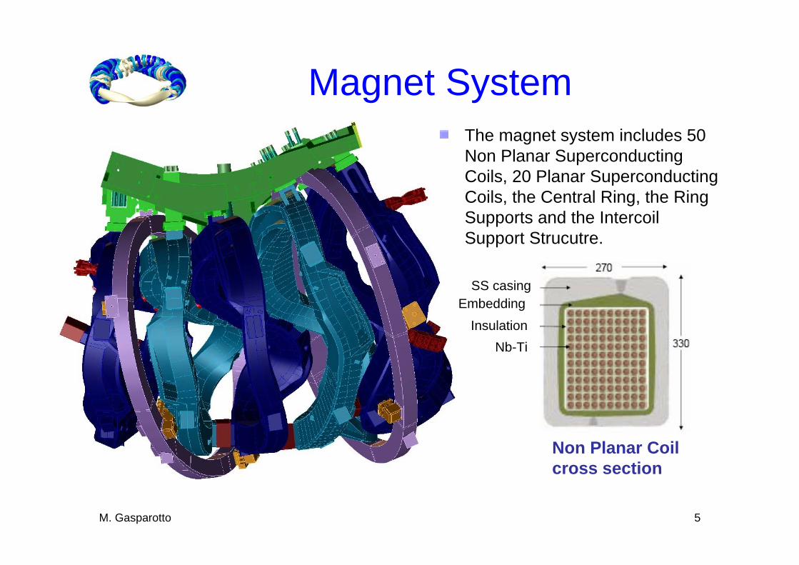
Magnet System
Non Planar Coil cross section
The magnet system includes 50 Non Planar Superconducting Coils, 20 Planar Superconducting Coils, the Central Ring, the Ring Supports and the IntercoilSupport Strucutre.
SS casingEmbedding
InsulationNb-Ti
M. Gasparotto 6
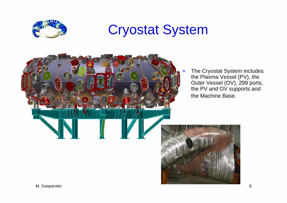
Cryostat System
The Cryostat System includes the Plasma Vessel (PV), the Outer Vessel (OV), 299 ports, the PV and OV supports and the Machine Base.

M. Gasparotto 7
Magnet System FE global model
Two FE models have beendeveloped:- ANSYS model (collaborationwith Efremov Institute – Russia)- ADINA model
The Coils are arranged torroidallyin 5 equal modules each oneconsisting of 2 semi-modules.
The FE model can be reduced to 1/10 of the whole machine (36°) introducing appropriate boundaryconditions derived from thesymmetries of the Magnet System
Maximum current in theNPC 18,4 MA turn
M. Gasparotto

M. Gasparotto 8
FE Global Model results
Displacement (m) in High Iota plasmaconfiguration
0
0.0075
0.015

M. Gasparotto 9
FE Global Model result
Von Misesstress (MPa) in High Iota plasmaconfiguration
M. Gasparotto
0
250
450

M. Gasparotto 10
Cryostat FE Global Model
Machine Base
Plasma Vessel includingsupports and ports
Outer Vessel

M. Gasparotto 11
The complete cryostat FE Global Model
M. Gasparotto
Finite Element Global Model:Outer vessel, Plasma vessel, Machine Base

M. Gasparotto 12
Cryostat FE Global Model
Displacement (mm) due to the weight and the operational scenario
-3.5 mm
-5.8 mm

M. Gasparotto 13
Main results of the FE analyses
The global behaviour of the Cryostat and Magnet Systems with respect to displacements and stresses are within the limits;The loads on the Central Supports and on the Intercoil support structure are very high and detailed FE analysis is necessary to identify critical areas;A number of welds both on the Magnet and on the Cryostat Systems have to be reinforced.
M. Gasparotto 14
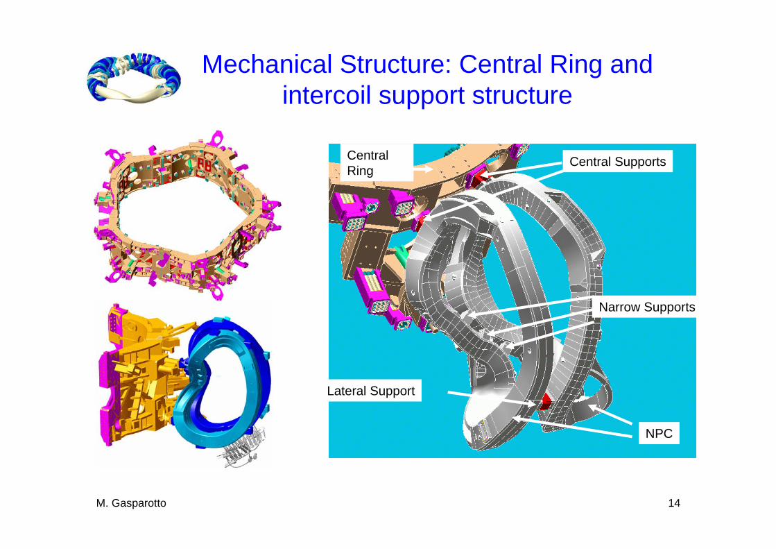
Mechanical Structure: Central Ring and intercoil support structure
Central Ring
Central Supports
NPC
Lateral Support
Narrow Supports

M. Gasparotto 15
Cross Section of a Typical Central Support Element Bolted Connection
Connection between the superconducting coilcasing and the Central Ring.
Superbolt nut
Superbolt washer
Sleeve
Interface Plate
Inconel Bolt (l=54.5 cm)
Extension
Shoulder
Wedge
Shim Plate
Central Support Element
Coil side Support sideCentral Ring
10 cm
M. Gasparotto 16
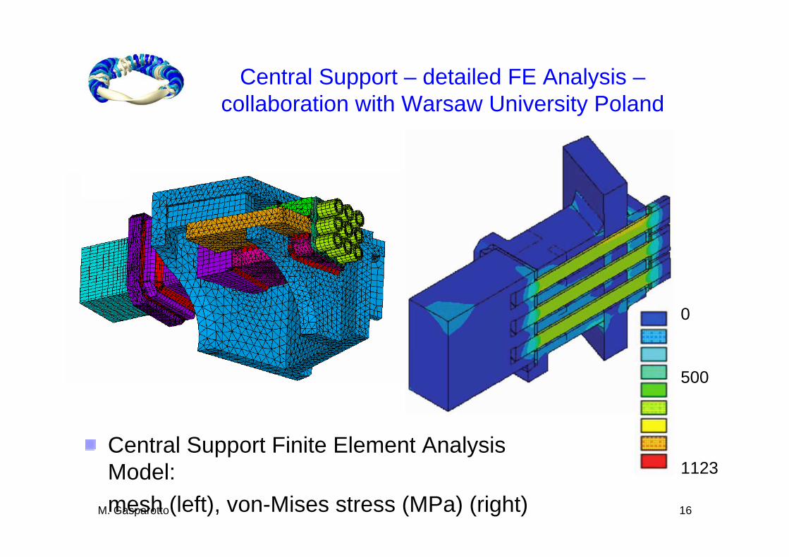
Central Support – detailed FE Analysis –collaboration with Warsaw University Poland
0
500
1123Central Support Finite Element Analysis Model: mesh (left), von-Mises stress (MPa) (right)
M. Gasparotto 17
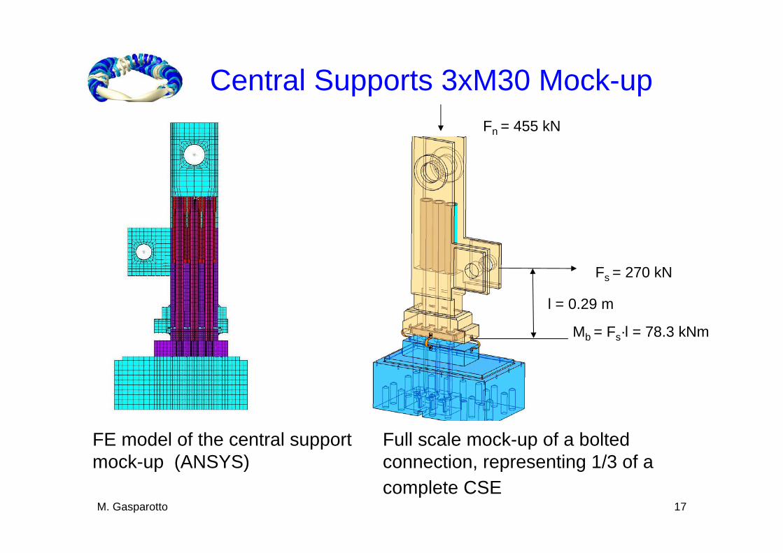
Central Supports 3xM30 Mock-up
Full scale mock-up of a bolted connection, representing 1/3 of a complete CSE
Fn = 455 kN
Fs = 270 kN
Mb = Fs·l = 78.3 kNm
l = 0.29 m
FE model of the central support mock-up (ANSYS)
M. Gasparotto 18
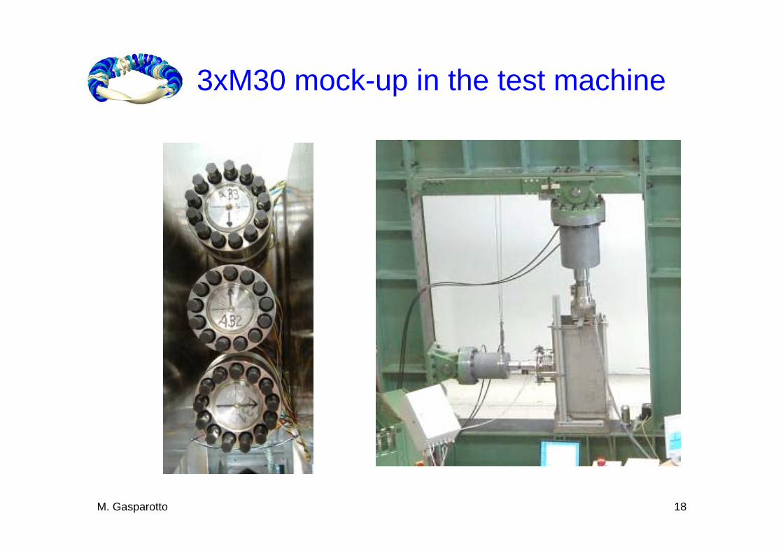
3xM30 mock-up in the test machine

M. Gasparotto 19
Preliminary experimental results
After welding the wedges, the preload of the bolts fell from 500kN to 370 kN. Consequently, during assembly the bolts should be re-tightened;The mechanical limit was reached when the applied loads were equal to 1.2 times the nominal ones. Significant plastic deformations started in some critical areas;No significant change in the bolt preloads was observed after the tests;The different parts have been disassembled without problems, no significant deformations or damages on the surfaces were observed.

M. Gasparotto 20
Narrow Support Element –Detailed Design
Dust protectionWave spring
Sliding surfaceMoS2 coatedPad in Al-BronzePad frame
10 cm
Central Ring
Central Supports
NPC
Lateral Support
NarrowSupports
M. Gasparotto 21
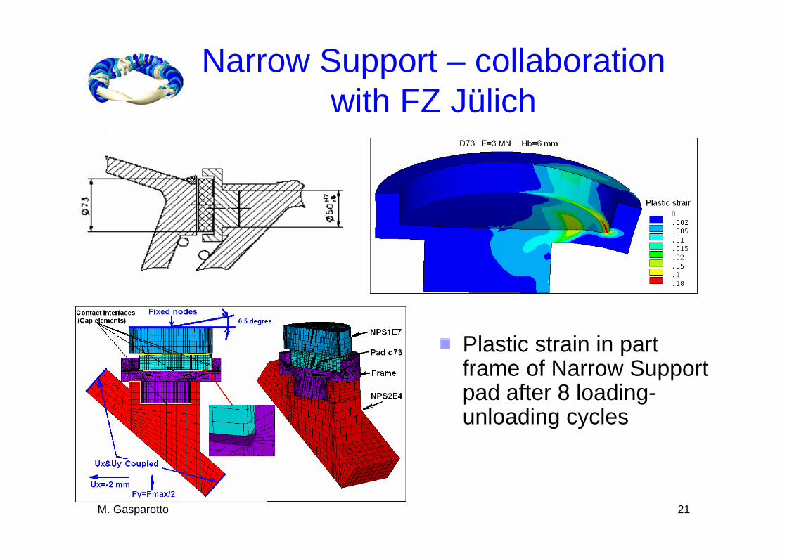
Narrow Support – collaborationwith FZ Jülich
Plastic strain in partframe of Narrow Support pad after 8 loading-unloading cycles

M. Gasparotto 22
Narrow Support Design: Critical Issues
The normal loads acting on the NS elements are very sensitive to the gap thickness between the pad and the sliding surface at the start up of the experiment (4K and zero electrical current in the coils). Very accurate assembly procedure has to be developed in order to keep the assembly tolerance as low as possible.
The sliding and tilling motions have to happen smoothly to avoid sudden release of elastic energy (“stick and slip”) which could trigger a quench in the superconductor coils.

M. Gasparotto 23
Narrow Supports Tests - KRP
77K Vacuum friction test device for the narrow support pads
Narrow support pads transmitting forces between coils during magnet energization
Normal load < 1.5 MN
Sliding < 5 mm
Tilting < 1°

M. Gasparotto 24
Narrow support test results
Stick-slip is more sensitive in cryo vacuum tests than in RT tests.No stick-slip is present in cryo-vacuum tests after more than 4000 cycles, when the sliding surfaces (Al-bronze pad and SS counter-face) are coated by MoS2 and the roughness is kept as low as possible (Rz < 1µm)The friction factor between the Al-bronze pad and SS sliding surface in cryo-vacuum tests was lower than 0.08.

M. Gasparotto 25
Lateral Supports Tests
Welding tests at FZJ on the lateral support elements (LSE)
NPC
Lateral Support
Narrow Supports
Central SupportsCentral Ring
- Average parallel displacement: 0.5-1.5mm
- Tilting: lower than 0.2°

M. Gasparotto 26
Conclusion
The main critical issues in the W7-X design derive from the complexity of the 3D geometries, high dimensional accuracy to bereached, the limited available spaces and the high loads in the magnet system.
The optimisation of the design of the mechanical structure leads to a system of support elements based on:
CS connecting the coil casing to the central ring by a bolted connection; NS connecting the NPC in the inner region by sliding contacts;LS connecting the NPC in the outer regions by welded connections with the exception of those between semi modules and modules which are realised by bolted connections.
Extensive FE models and tests have been performed and are in progress to validate the adopted solutions.

M. Gasparotto 27