crashworthiness of composites...
TRANSCRIPT

Joint Advanced Materials & Structures Center of Excellence www.jams-coe.org
Crashworthiness of Composites Structures
Gerardo Olivares1 (PI), Juan Acosta
2 (co-PI), Chandresh Zinzuwadia
3
National Institute for Aviation Research, Wichita, KS, 67260-0093
Suresh Keshavanarayana4 (co-PI)
Wichita State University, Wichita, KS, 67260-0044
and
Allan Abramowitz5
FAA William J. Hughes Technical Center, Atlantic City, NJ, 08405
ABSTRACT
Predictable computational tools, based on experimental and analytical methods, are developed to
support the design, evaluation, and optimization of the dynamic structural response of composite
airframes. Crashworthiness structural requirements such as the evaluation of survivable volume,
the retention of items of mass, deceleration loads experienced by occupants, and emergency egress
paths are identified by developing detailed finite element models of metallic narrow-body
transport aircraft to study the crashworthiness behavior of aircraft structures during survivable
impacts. At the coupon level, high speed test methods are being investigated experimentally and
numerically not only for material property generation but also for material model development; a
Round- Robin High Strain Rate Testing Material dynamic characterization of the in-plane tensile
material properties of CMH-17 material Toray - T700G/2510 PW carbon/epoxy is conducted over
a wide range of strain rates ranging between 0.01 to 250 s-1 in collaboration with four research
partners. At the sub-assembly level, a finite element model of 10-ft. fuselage section of a metallic
narrow-body transport is developed and used to study the energy absorbing capabilities of
individual structural members. Fasteners are identified as one of the major energy absorption
components. The ability of fastener modeling techniques to capture joint behavior for dynamic
loading applications is investigated. Tensile testing of single load transfer specimens is conducted
and results are used to verify different fastener finite element models. Tests are conducted at
speeds ranging from quasi-static up to 100 in/s. At the full scale level, the 10-ft. section is validated
with experimental data of a drop test conducted at the FAA technical center.
1 Technical Director Crash Dynamics, NIAR 2 Senior Research Engineer, NIAR 3 Research Engineer, NIAR 4 Associate Professor, Department of Aerospace Engineering, 228 Wallace Hall 5 Technical Monitor, RPD Manager, 502 Crashworthiness, AJP-6340, Bldg.210.

Joint Advanced Materials & Structures Center of Excellence
www.jams-coe.org
INTRODUCTION
The introduction of composite airframes warrants an assessment to evaluate that their
crashworthiness dynamic structural response provides an equivalent or improved level of safety
compared to conventional metallic structures. This assessment includes the evaluation of the survivable
volume, retention of items of mass, deceleration loads experienced by the occupants, and occupant
emergency egress paths. In order to design, evaluate, and optimize the crashworthiness behavior of
composite structures it is necessary to develop experimental and numerical methods and predictable
computational tools.
The advances in computational tools combined with coupon/component level testing allows for a
cost-effective approach to study in depth the crashworthiness behavior of aerospace structures. A
building block approach is used to assess the crashworthiness dynamic structural response of composite
airframes. Current research programs are conducted at the first two levels of the building block:
At Coupon Level: High speed test methods are being investigated experimentally and
numerically not only for material property generation but also for material model development
(Dynamic Characterization of Round Robin Material).
At Element Level: Numerical tools used to model structural joints are being evaluated (Modeling
Fastener Joints for Crashworthiness Simulations).
PROGRAM I – DYNAMIC CHARACTERIZATION OF ROUND ROBIN MATERIAL
Open literature reports variations in the material response of most materials when subjected to
large strain rates. High strain rates occur in airplane/automobile accidents and other engineering
applications such as impact or bird-strike events, plastic flow close to the tip of a fast propagating crack,
high speed metal forming, etc. [1]. Before including such effect in numerical modeling of structures,
appropriate constitutive equations need to be developed. Characterizing the behavior of composites
under dynamic loading is not an easy task. Baselines for the stress-strain behavior of composites are
generated at quasi-static to slow strain rates (<1 s-1
) using traditional testing machines and load sensing
devices. However, at high strain rates, generating stress-strain curves represents a challenge; several test
apparatus are used to account for different strain rate ranges. Hence different load measurement methods
are used. In addition, there is not a standard procedure for extracting iso-strain rate curves.
The crashworthiness working group (CWG) of the CMH-17 has been conducting a round robin
exercise to evaluate/compare the different numerical methods for simulating crushing behavior of
energy absorption devices made of laminated composites. The first sets of simulations are limited to
material properties generated at quasi-static rates. Future simulations will address the simulation of
crushing behavior under dynamic loading thus requiring appropriate material constitute properties
generated at representative strain rates. However, due to the wide range of test methods used by
researchers in the past, no standard exists for conducting such tests but only guidelines [2]. The current
investigation aims to generate rate sensitive tensile properties for the material being used by the CWG of
the CMH-17 at selected strain rates up to 250 s-1
. A secondary objective is to evaluate the test/method
apparatus, specifically the load measurement method, employed by the participating laboratories.

Joint Advanced Materials & Structures Center of Excellence
www.jams-coe.org
Experimental Methods
Tensile specimens are fabricated using two material systems: 2024-T3 Aluminum and Toray
T700/2510 plain weave/epoxy (F6273C-07M). Newport NB321/7781 fiberglass epoxy is used to
fabricate tabs for the composite specimens. Specimens are manufactured and instrumented by
NIAR/WSU and distributed to all participating laboratories. The Aluminum specimens are used as a
control material to evaluate load measurement devices. Aluminum specimens are dog-bone specimens
fabricated per ASTM E8 but varied to accommodate an extended tab [3, 4]. Aluminum specimens are
instrumented with two Vishay strain gages: strain gage CEA-06-250UN-120 mounted on the extended
tab region and another gage EP-08-125BG-120 mounted directly on the gage area. The gage on the
extended tab is used to measure the load introduced to the specimen. Composite specimens are straight-
tabbed specimens with rectangular cross section per ASTM D3039 with dimensions varied for high
strain rate testing [5]. Laminated panels are manufactured with traditional vacuum bag prepreg lay-up
and cured in autoclave. Quality control is enforced by means of TTU C-Scans and fiber volume content
measurement. Specimens are fabricated in three different stacking sequences: [0°]4, [90°]4, and [±45°]4.
Composite specimens are instrumented with Vishay strain gages CEA-00-250UN-350 and CEA-00-
125UT-350.
Tests at quasi-static rates for baseline data are conducted at NIAR/WSU using a standard 22 kip
(100 kN) MTS servo-hydraulic machine and a 11 kip (48 kN) load sensor. Two type of test apparatus
are used by the participating laboratories for dynamic testing: a high stroke servo-hydraulic testing
machine and a tensile Split Hopkinson Pressure Bar (SHPB). The high stroke servo-hydraulic machine
is used in combination with a slack inducer device that allows for the actuator to accelerate to a desired
velocity. Each laboratory uses its own load sensor, set of gripping devices, connectors/adaptors, etc. In
general load sensors are piezo-electric load cells. Nominal strain rates are: 0.0004, 0.01, 1, 100, and 250
s-1
.
Results
The quasi-static material response of the composite material is characterized. Average material
properties are estimated for reference: the Modulus of Elasticity of [0°] specimens is 8.25 Msi (C.V.
4.3%), for [90°] specimens is 8.77 Msi (C.V. 5.4%), and for [±45°] specimens is 1.96 Msi (C.V. 7.3%).
The tensile strength for [0°] specimens is 160 ksi (C.V. 3.9%), for [90°] specimens is 148 ksi (C.V.
2.5%), and for [±45°] specimens is 29 ksi (C.V. 6.9%). Variability based on three (3) replicates is
calculated for reference purposes only.
Test results for 2024-T3 Aluminum show the stress-strain behavior of the material not to vary
with increasing strain rate during the elastic regime of deformation. In addition, no major variations are
seen in the failure strength of the material with increasing strain rate. However, flow stress seems to
increase as a function of strain rate.
Composite materials dynamic testing results before load correction show different trends
between laboratories when looking at the apparent tensile strength. Lab A, C, and D test results for [0°]
and [90°] specimens show larger apparent failure strengths with increasing strain rate up to nominal
strain rate 100 s-1
. After which there is a drop in the strength for nominal strain rate 250 s-1
. On the other
hand, Lab B results for [0°] and [90°] specimens show a drop in apparent failure strength with
increasing strain rate. Test results for [±45°] specimens from Lab A, C, and D show larger apparent

Joint Advanced Materials & Structures Center of Excellence
www.jams-coe.org
failure strengths with increasing strain rate. On the other hand, Lab B results for [±45°] specimens show
an unexpected drop in apparent failure strength for nominal strain rate 1 s-1
. Test results after load
correction from all laboratories for [0°] composite specimens do not show the material strength
increasing with strain rate. Similarly, [90°] specimens do not show significant sensitivity to strain rate
even though results show larger scatter when compared to [0°] specimens. Nevertheless, the strength of
[±45°] specimens increases as a function of strain rate in all laboratory results. Strain rates introduced by
the tensile SHPB differ from average strain rates introduced by the high stroke servo-hydraulic machine
due to the different specimen geometry and the capabilities of each test apparatus. Only nominal strain
rates above 100 s-1
can be compared. Results obtained using a tensile SHPB do not show the material
response of composite specimens in the fiber direction [0°] and [90°] to be strain rate sensitive for the
evaluated strain rates. On the other hand, results for [±45°] specimens show higher strength values with
increasing strain rate.
PROGRAM II – MODELING FASTENER JOINTS FOR CRASHWORTHINESS
SIMULATIONS
Mechanical joining using bolts and fasteners is the most widely used joining method in
aerospace industry. Metal and Composite Structures use fasteners as one of the primary joining entities
to facilitate slip resistance and load transfer. The current investigation used a 10-ft fuselage section
model created in a previous research program to identify the average number of fastener connections
that an aircraft structure of this type may have. Twenty two thousand and twelve (22,012) fasteners were
identified in a 10-ft section. Also, the model was used to study the energy dissipation characteristics of
the structure during a crash event. During a 30 ft/s drop test of the fuselage section the energy dissipated
through fastener joints was up to 43 % of the total energy for no cargo configurations. Given the role of
fastener joints in aircraft structural integrity, it is important to identify the available numerical tools to
account for this type of joints, and more importantly, which ones are suitable for crashworthiness
simulations of metallic and composite aircraft structures. The size of finite element models used for
crashworthiness evaluations imposes limitations to the level of detail when capturing localized effects.
The scope of the program was to define guidelines for modeling fastener joints for
crashworthiness simulations. The primary objective was to evaluate how accurate existing simplified
numerical techniques to model bolts/fasteners represent mechanical joints behavior under dynamic
loading. Simplified techniques were compared against complex models and validated with testing. The
key parameters for comparison included load transfer, energy dissipation, and computational time.
savings when being part of large structures models.
Experimental Methods – Material Characterization
A material characterization was conducted to generate the material properties required for
simulation of single joint specimens. The material system was Aluminum 2024-T3 Clad. Dog-bone
specimens were fabricated, instrumented, and tested. In-plane tension testing was conducted per ASTM
E 8 using a standard 22 kip (100 kN) MTS servo-hydraulic machine and a 5.5 kip (25 kN) load sensor.
Tests were conducted at a quasi-static rate of 0.05 in/min and strain was measured using strain gages and
a laser extensometer along with a Vishay 2210 signal conditioner. The material response in tension is
shown in Figure 1.

Joint Advanced Materials & Structures Center of Excellence
www.jams-coe.org
Figure 1. Aluminum 2024-T3 Clad Material Response.
Experimental Methods – Preload Measurement
The clamping force introduced by a Hi-lok fastener to the joint was characterized
experimentally. Hi-lok fasteners are designed for a specific preload range. It contains a hex nut that
would shear off when the load on the fastener reaches such range. When used in service, every part is
fastened per industry specifications such load is properly transferred between components. Therefore,
numerical models used to study load transfer and energy dissipation in crash events should account for
the preload in bolted joints. Not accounting for it may change the load path and the energy absorbing
characteristics of the structure.
The test specimen included two Aluminum 2024-T3 plates, a 5 Kip load cell calibrated in
compression (LWO-2 Transducer Techniques), a nut (HL-70), and a pin (HL-18). Several specimens
were fabricated. First, an interference fit hole was drilled in each plate. Subsequently, the preload in the
Hi-lok joint was introduced by directly clamping the load cell in between the two plates as shown in
Figure 3. The fastener was torqued using a torque wrench until the nut sheared off. The maximum load
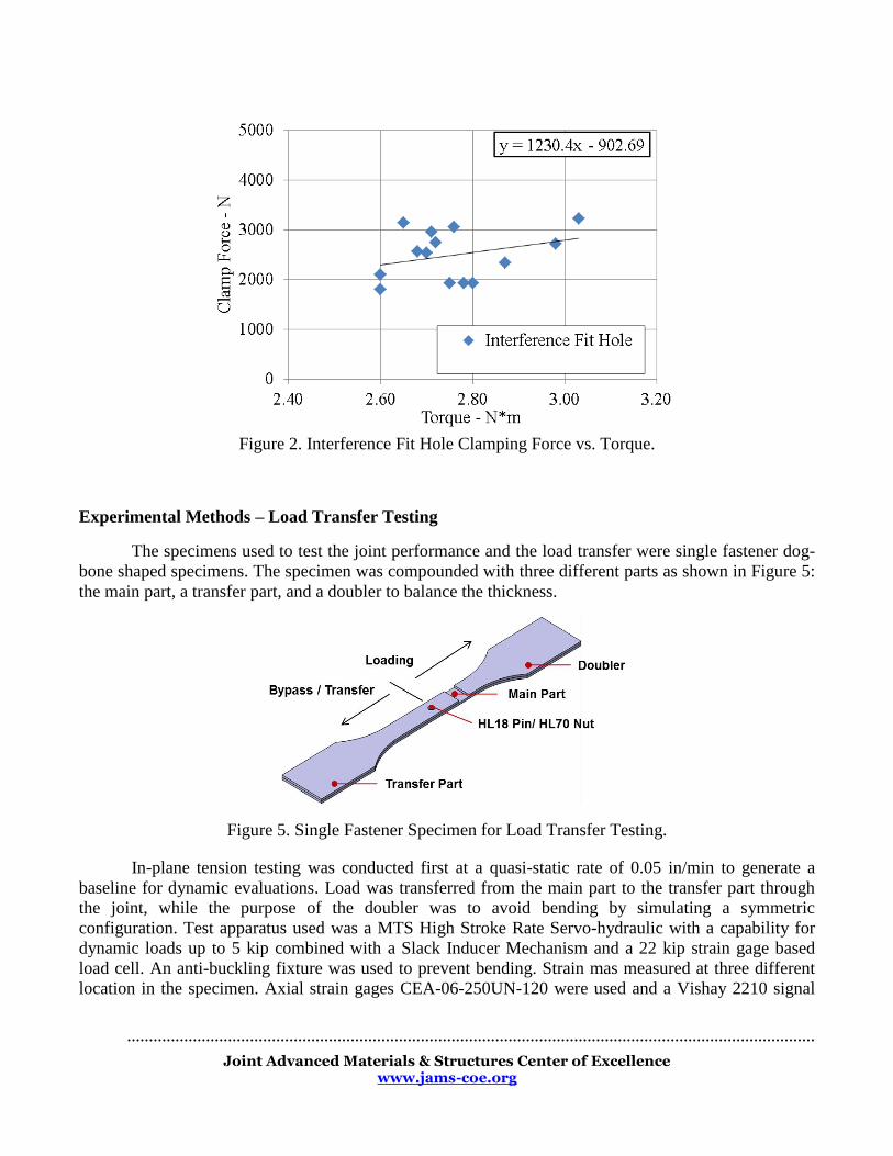
read by the load cell was recorded. Based on the response shown in figure 4 an average clamping force
was estimated for simulation.
Figure 1. Test Set-up and Specimen for Preload Measuring.
Joint Advanced Materials & Structures Center of Excellence
www.jams-coe.org
Figure 2. Interference Fit Hole Clamping Force vs. Torque.
Experimental Methods – Load Transfer Testing
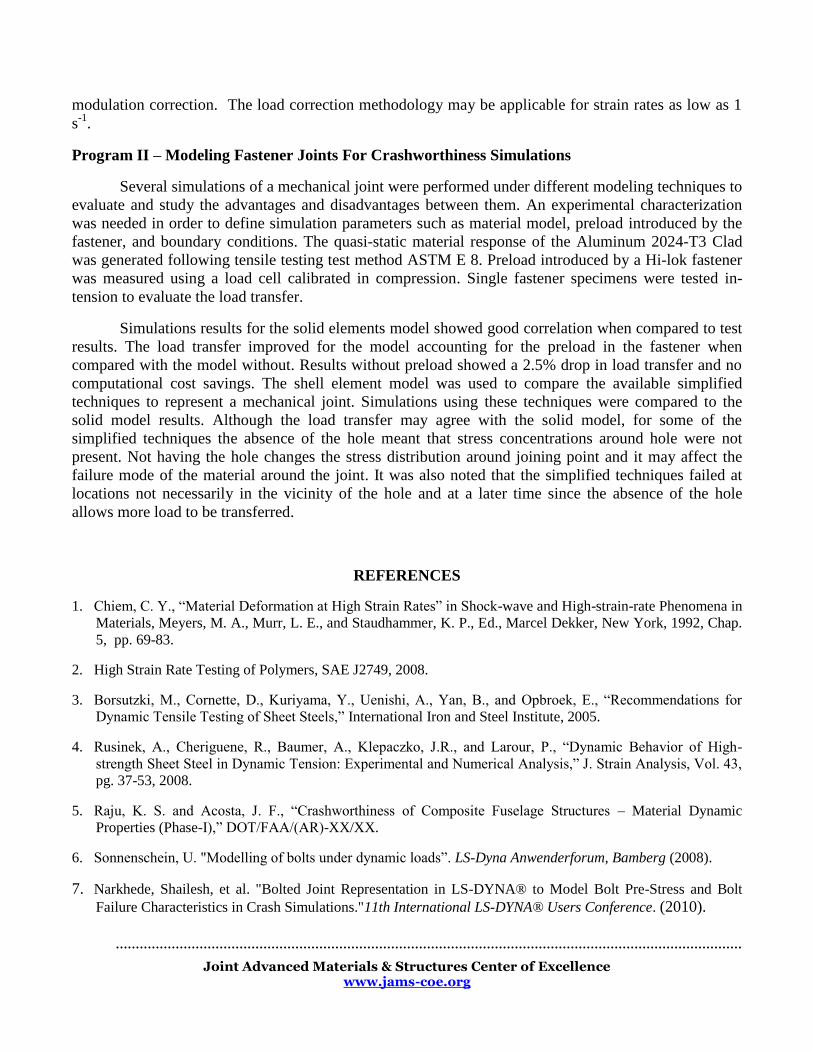
The specimens used to test the joint performance and the load transfer were single fastener dog-
bone shaped specimens. The specimen was compounded with three different parts as shown in Figure 5:
the main part, a transfer part, and a doubler to balance the thickness.
Figure 5. Single Fastener Specimen for Load Transfer Testing.
In-plane tension testing was conducted first at a quasi-static rate of 0.05 in/min to generate a
baseline for dynamic evaluations. Load was transferred from the main part to the transfer part through
the joint, while the purpose of the doubler was to avoid bending by simulating a symmetric
configuration. Test apparatus used was a MTS High Stroke Rate Servo-hydraulic with a capability for
dynamic loads up to 5 kip combined with a Slack Inducer Mechanism and a 22 kip strain gage based
load cell. An anti-buckling fixture was used to prevent bending. Strain mas measured at three different
location in the specimen. Axial strain gages CEA-06-250UN-120 were used and a Vishay 2210 signal

Joint Advanced Materials & Structures Center of Excellence
www.jams-coe.org
conditioner. The strain gages were placed to measure the strains experienced by the different parts. The
test set-up and strain gage locations are shown in Figure 6.
Figure 6. Test Set-up and Specimen Instrumentation.
Load transfer results are shown in Figure 7 for each test conducted. Load transfer was estimated
by comparing strain gage measurements at location 2 vs. location 1. The percentage load transfer is
given by:
[ (
)]
where SG 1 and SG 2, are the strain measurements (mm/mm).

Joint Advanced Materials & Structures Center of Excellence
www.jams-coe.org
Figure 7. Percentage Load Transfer.
Analysis Methods
Once the joint behavior was characterized experimentally along with the average fastener
preload, different simulation techniques were evaluated. The solver used in present work was LS-Dyna.
However, most commercial solvers provide equivalent simulation approaches to represent mechanical
joints. In addition, complex solutions have been developed by users after combining simplified methods
aiming to account for localized effects.
In this research program, a solid element model of the fastener and the specimen was built to
generate a baseline for simulation. Then, the joint behavior was evaluated using a shell element model of
the specimen and joining methods computationally cost efficient, so that they could be used accurately
in large scale aerospace structure models. First set of simulations used a complex model representing the
specimen and the anti-buckling fixture using solid 3D elements and a fine mesh as seen in Figure 8. The
model was built with solid elements with nominal size of 0.206 mm. Boundary conditions were defined
to constrain the bottom nodes of the specimen not to move in any direction. A prescribed translational
displacement in longitudinal direction was applied to the top set of nodes at a quasi-static rate. The anti-
buckling fixture was also modeled using solid elements and constrained in the same way as it was tested
(to avoid out of plane displacements). Different contact types were used between the specimen and the
bolt shank and nut and also between the whole jointed specimen and the anti-buckling fixture.
In the shell element model, bottom nodes were contained not to move in any direction and a
prescribed translational displacement in longitudinal direction was applied to the top set of nodes at a
quasi-static rate. Various simplified bolt modeling techniques were evaluated using this model and
compared to solid model results and validated with the experimental results. Examples of the evaluated
techniques included spotweld beams, beams with an elastic patch, spider web connections, or beams
with rigid links as shown in Figure 9.

Joint Advanced Materials & Structures Center of Excellence
www.jams-coe.org
Figure 8. Single Faster Specimen Solid Elements Model.
Figure 9. Available Simplified Joint Simulation Techniques.
Other fastener modeling approaches have been developed by Ls-Dyna users by combining
simple techniques. One approach combines the simplicity of beam elements with a spider connection
and a solid element modeling [6]. Null beams are modeled around the holes for contact and the bolt
shank is modeled with type 9 spotweld-beam elements. Shell elements are used to model the bolt head
and the nut as seen in Figure 10. Another example of bolt modeling uses a beam element at the center of
the hole to model the Bolt shank. Then, another beam element is connected to the periphery of bolt hole
using contact springs. Shell element patches representing the bolt head and the nut are modeled as rigid
and constrained using extra nodes [7]. A schematic representation of this method appears in Figure 11.
This approach with a beam model is advantageous if failure forces for bolted joint are known under
different conditions.

Joint Advanced Materials & Structures Center of Excellence
www.jams-coe.org
Figure 10. Beam-Spider-Web Combination with Solid Modeling [6].
Figure 11. Shell Elements, Beam Element, and Contact Springs Combination [7].
Results
Simulation results obtained with the 3D model were compared and validated with the
experimental results. Two different simulations were conducted, one taking into account the existing
preload introduced by the bolt and a second one without it. The preload was introduced in Ls-Dyna
using INITIAL_STRESS_SECTION option. The model with preload showed better correlation when
compared to test data while the model without preload showed a 2.5% drop in load transfer as shown in
Figure 12.

Joint Advanced Materials & Structures Center of Excellence
www.jams-coe.org
Figure 12. Effect of Preload in Single Fastener Solid Model Compared with Experimental Results.
SUMMARY AND CONCLUSIONS
Program I – Dynamic Characterization Of Round Robin Material
Test of 2024-T3 Aluminum specimens is conducted to evaluate the capabilities of the load
sensor. The material response, generated using the strain gage mounted on the tab as load measurement
device, does not show sensitivity to the evaluated strain rates over the elastic regime. The load measured
this way can be used for the load correction methodology since it is not being modulated by the load
train effect. The effect of higher strain rates on the material response, if any, is seen as an increment in
flow stress as a function of strain rate.
The quasi-static material response of the composite material is generated as a baseline for
estimating the effect of nominal strain rates as high as 250 s-1
. Before correction, the material strength in
the fiber direction [0°] and [90°] seems to increase as a function of strain rate. However, there is a
sudden drop above nominal strain rate 100 s-1
. On the other hand, the strength of [±45°] specimens
seems to increase as a function of strain rate. After load correction, the material response of composite
specimens in the fiber direction [0°] and [90°] does not show significant sensitivity to the evaluated
strain rate across laboratories. However, the response of the off-axis orientation [±45°] still shows some
sensitivity to high strain rates. Regardless the difference between actual strain rates introduced by each
test apparatus, the SHPB results agree with servo-hydraulic machine results after load correction; the
material response in the fiber direction [0°] and [90°] does not show sensitivity to the evaluated strain
rates and the material response for the off-axis orientation [±45°] show a moderate increment in the
strength with increasing strain rate.
High stroke servo-hydraulic machines used in combination with a slack inducer device show to
be suitable test apparatuses for conducting tensile testing at medium strain rates. However, the force
signal measured with piezoelectric load cells is modulated by the grips, adapters, and pins present in the
load train. Hence, the material response for medium strain rates is only apparent before signal
Joint Advanced Materials & Structures Center of Excellence
www.jams-coe.org
modulation correction. The load correction methodology may be applicable for strain rates as low as 1
s-1
.
Program II – Modeling Fastener Joints For Crashworthiness Simulations
Several simulations of a mechanical joint were performed under different modeling techniques to
evaluate and study the advantages and disadvantages between them. An experimental characterization
was needed in order to define simulation parameters such as material model, preload introduced by the
fastener, and boundary conditions. The quasi-static material response of the Aluminum 2024-T3 Clad
was generated following tensile testing test method ASTM E 8. Preload introduced by a Hi-lok fastener
was measured using a load cell calibrated in compression. Single fastener specimens were tested in-
tension to evaluate the load transfer.
Simulations results for the solid elements model showed good correlation when compared to test
results. The load transfer improved for the model accounting for the preload in the fastener when
compared with the model without. Results without preload showed a 2.5% drop in load transfer and no
computational cost savings. The shell element model was used to compare the available simplified
techniques to represent a mechanical joint. Simulations using these techniques were compared to the
solid model results. Although the load transfer may agree with the solid model, for some of the
simplified techniques the absence of the hole meant that stress concentrations around hole were not
present. Not having the hole changes the stress distribution around joining point and it may affect the
failure mode of the material around the joint. It was also noted that the simplified techniques failed at
locations not necessarily in the vicinity of the hole and at a later time since the absence of the hole
allows more load to be transferred.
REFERENCES
1. Chiem, C. Y., “Material Deformation at High Strain Rates” in Shock-wave and High-strain-rate Phenomena in
Materials, Meyers, M. A., Murr, L. E., and Staudhammer, K. P., Ed., Marcel Dekker, New York, 1992, Chap.
5, pp. 69-83.
2. High Strain Rate Testing of Polymers, SAE J2749, 2008.
3. Borsutzki, M., Cornette, D., Kuriyama, Y., Uenishi, A., Yan, B., and Opbroek, E., “Recommendations for
Dynamic Tensile Testing of Sheet Steels,” International Iron and Steel Institute, 2005.
4. Rusinek, A., Cheriguene, R., Baumer, A., Klepaczko, J.R., and Larour, P., “Dynamic Behavior of High-
strength Sheet Steel in Dynamic Tension: Experimental and Numerical Analysis,” J. Strain Analysis, Vol. 43,
pg. 37-53, 2008.
5. Raju, K. S. and Acosta, J. F., “Crashworthiness of Composite Fuselage Structures – Material Dynamic
Properties (Phase-I),” DOT/FAA/(AR)-XX/XX.
6. Sonnenschein, U. "Modelling of bolts under dynamic loads”. LS-Dyna Anwenderforum, Bamberg (2008).
7. Narkhede, Shailesh, et al. "Bolted Joint Representation in LS-DYNA® to Model Bolt Pre-Stress and Bolt
Failure Characteristics in Crash Simulations."11th International LS-DYNA® Users Conference. (2010).