cracks in welded steel girders on the steel bridge … · the 65-foot welded span in the two-span...
TRANSCRIPT

CRACKS IN WELDED STEEL GIRDERS ON THE STEEL BRIDGE AT FAST
Stephen M. Dick, PE, SE, PhD, Principal InvestigatorTransportation Technology Center, Inc.
55500 DOT Road, Pueblo, CO 81001Phone: (719) [email protected]
Robert J. Connor, PhD, Associate Professor of Civil EngineeringPurdue University
School of Civil Engineering550 Stadium Mall Drive
West Lafayette, IN 47907Phone: (765) [email protected]
Duane Otter, PhD, PE, Principal InvestigatorTransportation Technology Center, Inc.
55500 DOT Road, Pueblo, CO 81001Phone: (719) [email protected]
Jason Lloyd, CE, Research EngineerPurdue UniversityBowen Laboratory
1020 S River RdWest Lafayette, IN 47907Phone: (765) 494-2220
Word Count: 3,584
ABSTRACT
The 65-foot welded span in the two-span steel bridge at the Facility for Accelerated Service Testing has developed two major web and tension flange cracks, as well as numerous cracks in secondary members, during 15 years of service under heavy axle load traffic. The two major cracks appear to have initiated by constraint-induced fracture (CIF). This mechanism has caused some notable failures in highway bridges. In order to help railroad bridge owners prevent similar occurrences on their bridges, the paper describes conditions that can lead to CIF. The paper also presents the results of fractographic analysis and material characterization tests conducted on the most recent crack sample. In addition, strain readings, nondestructive testing results, and traffic history are presented.
The welded steel girder span remains in service with one of the major cracks continuing to accumulate fatigue cycles. Several safety systems are in place. Regular inspections and
© AREMA 2013® 711

ultrasonic readings are used to monitor for changes and safety of continued operations. At the other crack location, a major repair was installed where a sizable sample was removed for the fractographic analysis.
INTRODUCTION
The two-span steel bridge at the Facility for Accelerated Service Testing (FAST) at the Transportation Technology Center (TTC) continues to provide railway bridge engineers with results to help extend the life of existing railroad bridges. The heavy axle load (HAL) traffic operation subjects the spans to higher forces than would typically be experienced in revenue service, providing quicker results, as well as an indication of the issues that might arise if axle loads are increased. The 101-year-old 55.5-foot riveted girder span is providing results typical of an older span with evidence of years of corrosion. The 56-year-old 65-foot welded girder span is providing results typical of more recent welded construction, with its fatigue-sensitive details. Both spans are serving to test the performance of various repair techniques.
Past test results have shown the importance of reducing dynamic loads by removing rail joints (1, 2, 3). Current results indicate that corrugated rail can also produce high dynamic loads,resulting in a significant increase in fatigue damage. For operation of HAL traffic over bridges, it is recommended that the rail surface be maintained as smooth as possible and free of discontinuities in order to minimize dynamic loading on the structure.
The accelerated service environment at FAST is provided by running a 110-car HAL train equipped with 315,000-pound cars, pulled by three SD70 six-axle locomotives. Normal train operations are at 40 miles per hour. The train at FAST does not usually contain any cars with flat wheels or other defects that might produce large wheel impacts. The FAST steel bridge is described in the references (1, 2, 3, 4, 5, 6).
RECENT CRACKS IN 65-FOOT WELDED GIRDER SPAN
In April 2012, several new cracks were noted in the 65-foot welded girder span, and rapid growth was noted in several existing cracks. Most significantly, a second major web and tension flange crack developed in the 65-foot welded girder span just before the summer shutdown of FAST train operations. All cracks in the welded span appear to have initiated at weld details.
Figure 1 shows the major web and tension flange 8-inch crack, which is very similar to the previous major web and tension flange crack that initiated in 1998 (4). Both cracks appear to have initiated where a horizontal gusset plate from the bottom lateral bracing system is welded to the web of the girder at a vertical web stiffener location. The result is a small area with intersecting welds that is constrained from movement in all three directions. The steel at this location is unable to yield or deform under load, resulting in a brittle crack initiation termed constraint-induced fracture (CIF), as reported by Connor et al (7). This phenomenon has resulted in significant failures of welded steel girders in at least three highway bridges (7, 8).
© AREMA 2013®712

Figure 1. New 8-inch Crack in Web and Tension Flange of 65-foot Welded Girder Span
At the direction of the Association of American Railroads (AAR) Bridge Technical Advisory Group (TAG), a sample of the cracked gusset plate was cut out and sent to Purdue University for fractographic analysis and material characterization.
Figure 2 shows the sample that was cut out of the span. Figure 3 shows the repair installed on the welded span in the area from which the sample was removed. Because of the amount of material removed with the sample, the repair is much bigger than would otherwise have been needed. The repair was based on a similar repair installed on one highway bridge that experienced a large CIF crack (7).
© AREMA 2013® 713

Figure 2. Sample Removed for Fractographic Analysis of Major Crack
Figure 3. Repair Installed on Web and Tension Flange of 65-foot Welded Girder Span
© AREMA 2013®714

All of the other cracks noted in the same time frame were in secondary members including bracing, stiffeners, and gusset plates. A variety of repairs were installed, using bolted splices and doublers as much as possible. The AAR Bridge TAG was again consulted for guidance. In some cases, weld repairs were made, whereas a bolted repair would have required much more extensive work. Performance of all of these repairs is being monitored.
INCREASED DYNAMIC LOADS CAUSED BY CORRUGATED RAIL
Dynamic loads from corrugated rail and bolted rail joints cause a severe increase in the local stresses and strains of railroad bridges. One of the most effective ways to reduce the stress state in railroad bridges in order to carry HAL traffic is to maintain a smooth continuous rail surface across the bridge and the adjoining approach track. On the FAST steel bridge, there has been strong correlation between presence of rail joints or corrugated rail on the bridge and crack initiation and growth. Under HAL traffic, there is less reserve capacity in the bridge to be able to withstand these additional loads, which result in the need for additional maintenance and repairs.
The cause of the increased rate of crack initiation and crack growth in each one of the secondary member cases is suspected to be corrugated running rail on the welded span of the steel bridge during the spring of 2012. Just before the rails were ground, the corrugations were measured to have a depth of 0.090 inch on the north rail and 0.110 inch on the south rail. These corrugations were considered to be moderate. It had been noted that train traffic over the span was resulting in a great deal of audible noise from the bridge while the corrugated rail was in place. The noise subsided after the rail was ground smooth.
Figure 4 shows tension flange strains near the center of the 65-foot welded girder span measured under the HAL train operating over the corrugated rail compared to smooth rail after grinding. The peak strains are about 10 percent higher. The effective stress range for fatigue is about 15 percent higher using a rainflow cycle counting calculation. This higher stress range results in about a 50 percent increase in fatigue accumulation per train pass under corrugated rail as compared to smooth rail. Fatigue computations are based on the methodology recommended by the American Railway Engineering and Maintenance-of-Way Association (AREMA) in Chapter 15 of the Manual for Railway Engineering (9).
© AREMA 2013® 715

Figure 4. Increased Bridge Strains Due to Corrugated Rail on FAST Steel Bridge
Data from Transportation Technology Center, Inc.’s (TTCI’s) Instrumented Freight Car (IFC) also indicates increased dynamic activity when the corrugated rail was on the bridge. Side frame accelerations from the IFC with corrugated rail on the welded span of the steel bridge showed a vertical peak acceleration of 4 g and 12 events of 2 g or higher in the area of the steel bridge per train pass. After the rail was ground to a smooth condition, all peak values of side frame accelerations from the IFC were less than 2 g.
The rail corrugations were present over most of the welded span, which explains why the new cracks and rapid crack growth were noted at several secondary member locations throughout the span. In previous studies where rail joints were noted to increase crack activity, the crack activity was in close proximity to the joint. Corrugated rail introduces higher dynamic forces and increased crack activity over a more widespread area. It is likely that the corrugated rail also contributed to the initiation of the new major web and tension flange crack, which was found after 23 million gross tons (MGT) of traffic had run since the rail had been ground smooth on the bridge.
A bolted rail joint was installed on the welded span 3.2 MGT prior to the crack being found. The bolted rail joint was tight, had a perfect railhead match, and was located about 20 feet away from the location of the new crack. Strain and accelerometer measurements on the girder showed no significant impacts from this new bolted rail joint at the time the crack was found. The bolted rail joint has since been removed. It is possible that both the corrugated rail and the bolted rail joint combined to generate enough higher stress range cycles to initiate the major crack.
© AREMA 2013®716

LABORATORY TESTING OF SAMPLE
The portion of the girder containing the fracture was sent to Purdue University for fractographic evaluation and material testing. Figure 5 shows the specimen.
Figure 5. Photograph of Specimen used for Material Testing and Fractographic Examination
After examination, a strategy was developed to expose the fracture surface for examination. After strategic cutting, the specimen was cooled in liquid nitrogen and broken open for examination. Tensile, chemistry, and Charpy V-notch (CVN) tests were also performed on specimens obtained from the web and flange. The data is reported in Tables 1 and 2. Tensile and chemistry specimens were obtained from the flange and from the web. Based on the chemistry testing results, the steel is representative of American Society of Testing Materials (ASTM) A373 as shown on the original design plans; however, the yield strength of the samples was below the published requirement of 32 ksi. The yield point of the web sample was significantly lower than the specification, whereas the other mechanical properties met the published values.
Table 1. Results of Tensile Testing of Web and Flange
Specimen Tensile Strength (ksi)
Yield Strength
(ksi)Percent
ElongationPercent
Reduction of Area
Web 63.0 27.6 33 60Flange 60.5 31.9 42 66
© AREMA 2013® 717

Table 2. Results of Chemical Analysis of Web and Flange
Web FlangeElement Percent Element Percent Element Percent Element Percent
Al 0.005 Ni 0.027 Al 0.016 Ni 0.014As 0.010 P 0.006 As 0.005 P 0.006C 0.180 S 0.027 C 0.250 S 0.022
Co 0.016 Si 0.078 Co 0.025 Si 0.190Cr 0.027 Sn 0.007 Cr 0.022 Sn 0.004Cu 0.080 V 0.001 Cu 0.040 Ti 0.001Mn 0.620 W 0.003 Mn 0.690 V 0.001Mo 0.007 - - Mo 0.007 W 0.004
Figure 6 summarizes the results of the CVN data for the web and flange. Although CVN requirements were not in place at the time the bridge was fabricated, ASTM A709 fracture critical material (FCM) requirements are shown for comparative purposes for Zones 1, 2, and 3. Figure 6 shows that the steel for this bridge (produced in 1957) is not indicative of current CVN requirements for FCM, which are included in the recommendations of Chapter 15 of the AREMA manual (9). The results for the flange material indicate that none of the material was within specification, and the web was acceptable material only for Zone 1. The material conditions are in place for a potential catastrophic failure of the section.
Figure 6. Plot of CVN Data from Web and Flange of Girder
© AREMA 2013®718

Fractographic analysis was performed to identify the origin and cause of the fracture as well as to determine if crack extension occurred where the initial fracture arrested in the web and flange. Figure 7 summarizes the macro-fractographic examination. A large fatigue crack was observed to initiate at the weld toe of the weld between the gusset plate and the rolled angle braced member (See Figure 7).
Figure 7. Photographs Showing Fracture Surface
Examination of the fatigue crack surface revealed the crack grew in a slow and stable manner suggesting that the crack was present before the fracture occurred. Had the fracture occurred first, this large fatigue crack would have had to have grown very quickly. Based on inspection records, the fracture was observed approximately 26 MGT and 165,000 load cycles after the last complete inspection. Once the crack grew to the point of severing the gusset plate, the stress intensity within the very tight web gap would be expected to increase and hence, make fracture more likely. It is noted that the gusset plate itself was not directly welded to the transverse stiffener, but only to the angle lateral bracing and the web. The cross-frame angle at this location was welded directly to the transverse stiffener on the vertical leg with the horizontal leg welded to the gusset plate.
Further examination revealed the crack surface showed evidence of cleavage fracture with an initiation in the region where the gusset plate terminated at the vertical stiffener. Figure 8 is a close-up photograph of the opposite face of the fracture shown in Figure 7. Note the
© AREMA 2013® 719

chevron pattern on the web indicating the general origin of the fracture, which is shown in the oval where the gusset plate and web intersect. No evidence of fatigue crack growth was found in the location under the electron microscope. This is the same location that similar CIF failures occurred in the Hoan, SR 422, and Diefenbaker Bridges (7, 8). In all three cases, the fractures were brittle cleavage fracture and no fatigue crack growth was observed.
Figure 8. Close-up Photograph of Fracture Initiation Location
Examination of the crack termination in the web also revealed that the crack extended in fatigue about 1/8 to 3/16 inch from the location where the brittle fracture arrested. The examination revealed relatively large striations, suggesting the stress ranges were high at the crack tip, as expected. Considering the very small amount of extension further reinforces the observation the fracture was not present for very long prior to the time it was discovered.
Examination of the fracture at the point of crack arrest in the flange showed no signs of fatigue crack extension, which is of course inconsistent with expected behavior; i.e., a crack in the tension flange of a two-girder bridge would be expected to grow at a steady rate under cyclic
© AREMA 2013®720

loading. In addition, the fact that the facture arrested, though not unique, is also interesting. Based on the results of the CVN testing, it is clear that the crack did not arrest due to “unreasonably high” toughness of the flange, as evidenced by the CVN data presented in Figure 6. The crack also progressed approximately two-thirds of the way into the bottom flange. A similar fracture occurred at another joint in the same bridge 15 years earlier. That crack also arrested and is not believed to have extended in fatigue, because the girder has carried over 1,900MGT (12 million load cycles) of railroad loading with no significant growth. Typical peak stress from the train at FAST is approximately 8 ksi, while the typical stress range is approximately 4 ksi.
Since the tension flange is clearly subjected to tensile stresses (both dead load and live load), lack of fatigue crack propagation and the fracture arrest is possibly due to compressive residual stresses in the flange that are the result of fabrication and the rolling process. Considering its age, the plate may be universal mill plate, and it would be expected to have tensile residual stresses at the location the fracture terminated. However, if the flange plate was cut from a wider plate, compressive residual stresses could be expected (10). The type of plate is unknown. The longitudinal residual stresses from welding would be expected to produce compressive residual stresses, though likely small, at the location the fracture arrested (11). It is also worth noting that the span is entirely welded; i.e., there are no bolted joints in the main members or secondary members. Hence, the entire bridge was fabricated in the shop and shipped to the original site. This is also how it was removed from service and sent to TTC for installation at FAST. It is possible that during fabrication, specifically the welded installation of all of the secondary bracing members, introduced compressive residual stresses into the main girders, though again, these would be expected to be relatively small.
Thus, because it is not entirely clear why the fracture arrested in the flange or why the crack did not extend in fatigue in the flanges, the results in this span are not a reason to anticipate that other spans susceptible to CIF will act similarly.
CONCLUSIONS
The 65-foot welded girder span in the FAST steel bridge has developed two significant cracks in the lower web and partially in the tension flange. Data recorded on the span just prior to the initiation of the second crack shows that corrugated rail resulted in increased dynamic loading in the span, which generated a significant increase in the resulting fatigue accumulation per train pass.
Detailed laboratory examination of the recent crack reveals that it is similar to cracks in highway bridges attributed to CIF. Metallurgical and material property tests show the steel to have fracture toughness properties typical of the 1957 fabrication date, which are lower than those currently required for bridge steel. The first such crack has been in the tension flange for 15 years of service with no measured growth, and the second crack was removed before additional traffic was applied. While the fracture in the second crack arrested, it is not known whether or not the crack was fully arrested or might have propagated further with additional train traffic.
© AREMA 2013® 721

The bolted repair applied to the span has performed well under 122 MGT of HAL traffic. No increases in deflection have been noted. No significant changes in tension flange strains have been noted.
ACKNOWLEDGEMENTS
TTCI gratefully acknowledges Bowen Laboratory at Purdue University School of Civil Engineering for its voluntary services in testing of the crack specimen extracted from the welded bridge span. This research was sponsored by the AAR Strategic Research Initiatives Program. The authors acknowledge the support and guidance of this testing provided the AAR Bridge TAG, made up of railroad chief bridge engineers and AREMA structures committee chairs, and currently chaired by John Unsworth of Canadian Pacific Railway. REFERENCES1. Akhtar, M., D. Otter, B. Doe. October 2004. “Update: Cracks in the Welded Girders of
the Steel Bridge at FAST.” Technology Digest TD-04-014, AAR/TTCI, Pueblo, CO.2. Otter, D., M. Akhtar, B. Doe, D. Yoshino. September 2006. “Crack Development and
Growth in FAST Steel Bridge.” Proc. AREMA Conference, Louisville, KY.3. Akhtar, M., D. Otter, B. Doe. November 2007. “The Effects of Moveable Bridge Joint on
the Fatigue Life of Welded Braces of Open Deck Steel Bridge at FAST.” Technology Digest TD-07-037, AAR/TTCI, Pueblo, CO.
4. Otter, D., D. Oliva, R. Joy. December 1998. “Cracks in Welded Girders of the FAST Bridge.” Technology Digest TD-98-030, AAR/TTCI, Pueblo, CO.
5. Ninness, K., L. Tunna, D. Otter. August 2011. “Bracing and Lateral Deflections: VintageSteel Bridge Span at FAST.” Technology Digest TD-11-028, AAR/TTCI, Pueblo, CO.
6. Tunna, L., MC Jones, D. Otter. August 2011. “Characterization of a Vintage Riveted Steel Deck Plate Girder Bridge Span at FAST.” Technology Digest TD-11-029, AAR/TTCI, Pueblo, CO.
7. Connor, R.J., E. J. Kaufman, J. W. Fisher, W. J. Wright. March/April 2007. “Prevention and Mitigation Strategies to Address Recent Brittle Fractures in Steel Bridges.” Journal of Bridge Engineering, pp. 164–173.
8. Ellis, R.M., R. J. Connor. June 2013. “Investigation and Repair of the Diefenbaker Bridge Fracture.” IBC Paper 13-20, Proc. 30th Annual International Bridge Conference,Pittsburgh, PA.
9. American Railway Engineering Maintenance-of-Way Association. 2012. Manual for Railway Engineering, Lanham, MD.
10. Bjorhovde, R., J. Brozzetti, A. Alpsten, L. Tall. June 1971. “Residual stresses in thick welded plates,” Paper 335. FritzLaboratory Reports. http://preserve.lehigh.edu/engr-civil-environmental-fritz-lab-reports/335
11. The British Standards Institution. 2005. Guide to Methods for Assessing the Acceptability of Flaws in Metallic Structures, BS 7910:2005, London.
© AREMA 2013®722

List of Figures
Figure 1. New 8-inch Crack in Web and Tension Flange of 65-foot Welded Girder SpanFigure 2. Sample Removed for Fractographic Analysis of Major CrackFigure 3. Repair Installed on Web and Tension Flange of 65-foot Welded Girder SpanFigure 4. Increased Bridge Strains Due to Corrugated Rail on FAST Steel BridgeFigure 5. Photograph of As-Received Specimen Used for Material Testing and Fractographic ExaminationFigure 6. Plot of CVN Data from Web and Flange of GirderFigure 7. Photographs Showing Fracture SurfaceFigure 8. Close-up Photograph of Fracture Initiation Location List of Tables
Table 1. Results of Tensile Testing of Web and FlangeTable 2. Results of Chemical Analysis of Web and Flange
© AREMA 2013® 723

Sept
embe
r 29
–O
ctob
er 2
, 20
13In
dian
apol
is,
IN
Crac
ks in
Wel
ded
Stee
l G
irde
rs o
n th
e St
eel B
ridg
e at
FAS
TS
teph
en D
ick
–Pr
inci
pal I
nves
tigat
or, T
TCI
Rob
ert C
onno
r –As
soci
ate
Pro
fess
or, C
ivil
Eng
inee
ring,
P
urdu
e U
nive
rsity
Dua
ne O
tter –
Prin
cipa
l Inv
estig
ator
, TTC
I
Jaso
n Ll
oyd
–R
esea
rch
Eng
inee
r, P
urdu
e U
nive
rsity
© AREMA 2013®724

September 29 – October 2, 2013Indianapolis, IN
Summary of Loading Environment and Cracking
of TTC Girder
September 29 – October 2, 2013Indianapolis, IN
FAST Welded Steel Bridge
September 29 – October 2, 2013Indianapolis, IN
Bridge Girder Details
Fabricated and installed in 1957Welded fabrication uses typical details for the time period of constructionFabricated from ASTM A373 steel. This is a “weld friendly” version of ASTM A7 steelFirst installed by Pennsylvania RR on a branch line. Revenue loading was not extensive
September 29 – October 2, 2013Indianapolis, IN
General Conditions at FAST
Welded Steel Girder span installed in 1997Installed on the FAST HTL LoopSubjected to 2,800 Million Gross Tons (MGT)Loading consists of 110-cars, 3 locomotives
Locomotives are six-axle units with radial trucks to reduce rail wearUnit-train loading with 315,000-pound cars
September 29 – October 2, 2013Indianapolis, IN
Crack Development in Welded Span
Various cracks developed in bracing and stiffeners since installationStiffeners cracked due to transverse rotation of the top flangeInitial web and flange crack developed soon after installation (14 MGT HAL)Second web and flange crack discovered after 1,930 MGT HAL
September 29 – October 2, 2013Indianapolis, IN
Crack Development in Welded Span
First web-flange crack found in 1998Monitored since discoveryNo growth detected in crack
Second web-flange crack found in 2012Same type of crack as originalBracing detail similar between the crack locations
© AREMA 2013® 725

September 29 – October 2, 2013Indianapolis, IN
Crack Development in Welded Span
September 29 – October 2, 2013Indianapolis, IN
Crack Development in Welded Span
September 29 – October 2, 2013Indianapolis, IN
Factors in Crack Development
Constrained joint similar to details found in some high profile highway bridge failuresCorrugations in running rail on bridge developed higher impact loads
Average corrugation depth 0.010 inchAverage corrugation length 18 inchesFrequency of approximately 40 Hz
September 29 – October 2, 2013Indianapolis, IN
Strain Histogram with Corrugations
September 29 – October 2, 2013Indianapolis, IN
Fatigue Implications from Corrugations
Peak strains 10 percent higher than smooth rail surfaceEffective stress range 15 percent higher using rainflow calculationsFatigue damage accumulation 50 percent higher due to corrugations
September 29 – October 2, 2013Indianapolis, IN
Actions from Crack Discovery
AAR Bridge TAG decided that the second web-flange crack should be removed and testedDetail with crack removed from bridge and repaired with a bolted spliceCrack specimen sent to Purdue University for analysis
© AREMA 2013®726

September 29 – October 2, 2013Indianapolis, IN
Repair Location
September 29 – October 2, 2013Indianapolis, IN
Summary of Fractographic Examination of TTC Girder
September 29 – October 2, 2013Indianapolis, IN
Fractographic Examination
Portion of girder containing fracture shipped to Purdue for evaluation
CVN Testing of flange and webExposure of fracture surfaceIdentify fracture initiationIdentify any fatigue crack growth at crack tips
September 29 – October 2, 2013Indianapolis, IN
Material Properties
Plate Thickness(in)
Yield (ksi)
Tensile (ksi)
%Elongation
Flange 2-5/8 27.6 63.0 33
Web 5/8 31.9 60.5 42
A373 per drawings (weldable A7)Tensile testing
Fy of flange low for A373 (low limit 32 ksi)Chemistry composition
Meets A373 chemistry (sulfur a little low)
September 29 – October 2, 2013Indianapolis, IN
Findings – CVN DataCVN data obtained from web and flangeConsidering the low CVN values of flange at even 70 F
Fracture did not arrest due to the flange having unusually high toughness
Though not in place at the time the bridge was built, Zone 1 Non-FC requirements are 15 ft-lb at 70 F for grade 36 steel
This is the most lenient level of CVN energy requirements per AASHTO today
Zone 2 FC requirement is 25 ft-lb at 40 F — this steel is not close to meeting the requirement
September 29 – October 2, 2013Indianapolis, IN
Exposure of Fracture Surface
Piece saw cut into smaller piecesCooled in liquid nitrogen and broken open to expose crack surfaces
© AREMA 2013® 727
September 29 – October 2, 2013Indianapolis, IN
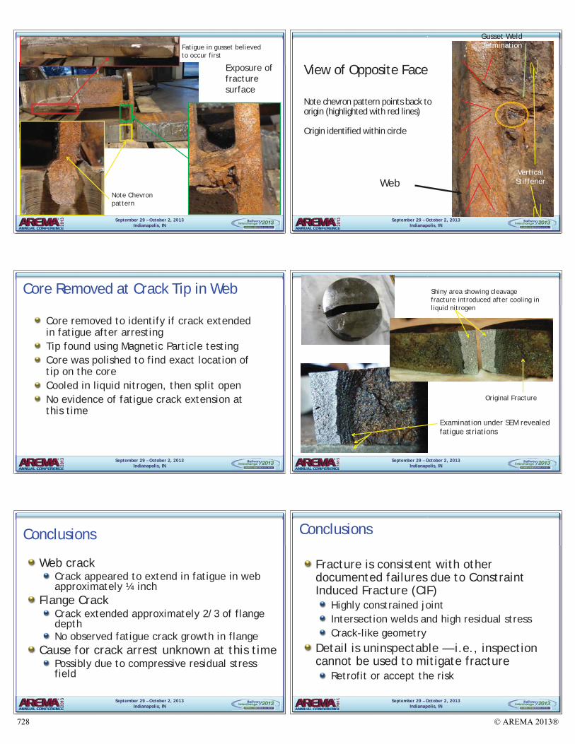
Fatigue in gusset believed to occur first
Note Chevron pattern
Exposure of fracturesurface
September 29 – October 2, 2013Indianapolis, IN
View of Opposite Face
Note chevron pattern points back to origin (highlighted with red lines)
Origin identified within circle
Web
Gusset Weld Termination
Vertical Stiffener
September 29 – October 2, 2013Indianapolis, IN
Core Removed at Crack Tip in Web
Core removed to identify if crack extended in fatigue after arrestingTip found using Magnetic Particle testingCore was polished to find exact location of tip on the coreCooled in liquid nitrogen, then split openNo evidence of fatigue crack extension at this time
September 29 – October 2, 2013Indianapolis, IN
Shiny area showing cleavage fracture introduced after cooling in liquid nitrogen
Original Fracture
Examination under SEM revealed fatigue striations
Details of Fracture Surface on Core
September 29 – October 2, 2013Indianapolis, IN
Conclusions
Web crackCrack appeared to extend in fatigue in web approximately ¼ inch
Flange CrackCrack extended approximately 2/3 of flange depthNo observed fatigue crack growth in flange
Cause for crack arrest unknown at this timePossibly due to compressive residual stress field
September 29 – October 2, 2013Indianapolis, IN
Conclusions
Fracture is consistent with other documented failures due to Constraint Induced Fracture (CIF)
Highly constrained jointIntersection welds and high residual stressCrack-like geometry
Detail is uninspectable — i.e., inspection cannot be used to mitigate fracture
Retrofit or accept the risk
© AREMA 2013®728