cr1000 measurement and control system - 筑波大学 · 2009. 9. 11. · warranty and assistance...
TRANSCRIPT

CR1000 Measurement andControl System
Revision: 1/09
C o p y r i g h t © 2 0 0 0 - 2 0 0 9C a m p b e l l S c i e n t i f i c , I n c .

Warranty and Assistance The CR1000 MEASUREMENT AND CONTROL SYSTEM is warranted by CAMPBELL SCIENTIFIC, INC. to be free from defects in materials and workmanship under normal use and service for thirty-six (36) months from date of shipment unless specified otherwise. Batteries have no warranty. CAMPBELL SCIENTIFIC, INC.'s obligation under this warranty is limited to repairing or replacing (at CAMPBELL SCIENTIFIC, INC.'s option) defective products. The customer shall assume all costs of removing, reinstalling, and shipping defective products to CAMPBELL SCIENTIFIC, INC. CAMPBELL SCIENTIFIC, INC. will return such products by surface carrier prepaid. This warranty shall not apply to any CAMPBELL SCIENTIFIC, INC. products which have been subjected to modification, misuse, neglect, accidents of nature, or shipping damage. This warranty is in lieu of all other warranties, expressed or implied, including warranties of merchantability or fitness for a particular purpose. CAMPBELL SCIENTIFIC, INC. is not liable for special, indirect, incidental, or consequential damages.
Products may not be returned without prior authorization. The following contact information is for US and International customers residing in countries served by Campbell Scientific, Inc. directly. Affiliate companies handle repairs for customers within their territories. Please visit www.campbellsci.com to determine which Campbell Scientific company serves your country. To obtain a Returned Materials Authorization (RMA), contact CAMPBELL SCIENTIFIC, INC., phone (435) 753-2342. After an applications engineer determines the nature of the problem, an RMA number is issued. Please write this number clearly on the outside of the shipping container. CAMPBELL SCIENTIFIC's shipping address is:
CAMPBELL SCIENTIFIC, INC. RMA#_____ 815 West 1800 North Logan, Utah 84321-1784
CAMPBELL SCIENTIFIC, INC. does not accept collect calls.
i
CR1000 Table of Contents PDF viewers note: These page numbers refer to the printed version of this document. Use the Adobe Acrobat® bookmarks tab for links to specific sections.
1. Introduction...............................................................1-1
2. Quickstart Tutorial....................................................2-1 2.1 Primer – CR1000 Data Acquisition ................................................... 2-1
2.1.1 Components of a Data Acquisition System.............................. 2-1 2.1.1.1 Sensors .............................................................................. 2-1 2.1.1.2 Datalogger ......................................................................... 2-1 2.1.1.3 Data Retrieval.................................................................... 2-1
2.1.2 CR1000 Mounting.................................................................... 2-2 2.1.3 Wiring Panel............................................................................. 2-2 2.1.4 Battery Backup......................................................................... 2-2 2.1.5 Power Supply ........................................................................... 2-2 2.1.6 Analog Sensors......................................................................... 2-4 2.1.7 Bridge Sensors.......................................................................... 2-6 2.1.8 Pulse Sensors............................................................................ 2-7 2.1.9 Digital I/O Ports ....................................................................... 2-7 2.1.10 RS-232 Sensors ...................................................................... 2-8 2.1.11 Input Expansion Modules....................................................... 2-9
2.2 Hands-on Exercise — Measuring a Thermocouple............................ 2-9 2.2.1 Connections.............................................................................. 2-9 2.2.2 PC200W Software Setup........................................................ 2-10
2.2.2.1 Programming with Short Cut........................................... 2-11 2.2.2.2 Connecting to the Datalogger .......................................... 2-16 2.2.2.3 Synchronizing the Clocks................................................ 2-16 2.2.2.4 Sending the Program ....................................................... 2-16 2.2.2.5 Monitoring Data Tables................................................... 2-17 2.2.2.6 Collecting Data................................................................ 2-18 2.2.2.7 Viewing Data................................................................... 2-19
3. Overview ....................................................................3-1 3.1 CR1000 Overview.............................................................................. 3-1
3.1.1 Sensor Support ......................................................................... 3-2 3.1.2 Input / Output Interface: The Wiring Panel.............................. 3-2
3.1.2.1 Measurement Inputs .......................................................... 3-2 3.1.2.2 Voltage Outputs................................................................. 3-4 3.1.2.3 Grounding Terminals......................................................... 3-4 3.1.2.4 Power Terminals................................................................ 3-5 3.1.2.5 Communications Ports....................................................... 3-5
3.1.3 Power Requirements................................................................. 3-6 3.1.4 Programming: Firmware and User Programs........................... 3-6
3.1.4.1 Firmware: OS and Settings................................................ 3-7 3.1.4.2 User Programming............................................................. 3-7
3.1.5 Memory and Data Storage........................................................ 3-8 3.1.6 Communications....................................................................... 3-8
3.1.6.1 PakBus............................................................................... 3-8 3.1.6.2 Modbus.............................................................................. 3-9

CR1000 Table of Contents
ii
3.1.6.3 DNP3 Communication....................................................... 3-9 3.1.6.4 Keyboard Display .............................................................. 3-9
3.1.7 Security................................................................................... 3-10 3.1.8 Care and Maintenance ............................................................ 3-11
3.1.8.1 Protection from Water ..................................................... 3-11 3.1.8.2 Protection from Voltage Transients ................................. 3-11 3.1.8.3 Calibration ....................................................................... 3-11 3.1.8.4 Internal Battery ................................................................ 3-11
3.2 PC Support Software........................................................................ 3-12 3.3 Specifications ................................................................................... 3-13
4. Sensor Support ........................................................ 4-1 4.1 Powering Sensors ............................................................................... 4-1
4.1.1 Switched Precision (-2500 to +2500 mV) ................................ 4-1 4.1.2 Continuous Regulated 5 Volt.................................................... 4-1 4.1.3 Continuous Unregulated Nominal 12 Volt ............................... 4-1 4.1.4 Switched Unregulated (Nominal 12 Volt) ................................ 4-2
4.2 Voltage Measurement......................................................................... 4-2 4.2.1 Electronic “Noise”: VoltDiff() or VoltSE()? ............................ 4-3 4.2.2 Measurement Sequence ............................................................ 4-4 4.2.3 Voltage Range .......................................................................... 4-4 4.2.4 Offset Voltage Compensation................................................... 4-6
4.2.4.1 Input and Excitation Reversal (RevDiff, RevEx = True)... 4-7 4.2.4.2 Ground Reference Offset Voltage (MeasOff = True) ........ 4-8 4.2.4.3 Background Calibration (RevDiff, RevEx, MeasOff = False)........4-8
4.2.5 Measurements Requiring AC Excitation .................................. 4-8 4.2.6 Integration................................................................................. 4-9
4.2.6.1 AC Power Line Noise Rejection........................................ 4-9 4.2.7 Signal Settling Time ............................................................... 4-11
4.2.7.1 Minimizing Settling Errors .............................................. 4-12 4.2.7.2 Measuring the Necessary Settling Time .......................... 4-12
4.2.8 Self-Calibration ...................................................................... 4-14 4.3 Bridge Resistance Measurements..................................................... 4-17
4.3.1 Strain Calculations.................................................................. 4-20 4.4 Thermocouple Measurements .......................................................... 4-22
4.4.1 Error Analysis......................................................................... 4-22 4.4.1.1 Panel Temperature ........................................................... 4-23 4.4.1.2 Thermocouple Limits of Error ......................................... 4-25 4.4.1.3 Accuracy of Thermocouple Voltage Measurement ......... 4-26 4.4.1.4 Noise on Voltage Measurement....................................... 4-27 4.4.1.5 Thermocouple Polynomial: Voltage to Temperature...... 4-27 4.4.1.6 Reference Junction Compensation: Temperature to Voltage .... 4-28 4.4.1.7 Error Summary ................................................................ 4-29 4.4.1.8 Use of External Reference Junction................................. 4-29
4.5 Pulse Count Measurement................................................................ 4-30 4.5.1 Pulse Input Channels P1 and P2 ............................................. 4-31
4.5.1.1 High-frequency Pulse (P1 – P2) ...................................... 4-32 4.5.1.2 Low-Level AC (P1 – P2) ................................................. 4-33 4.5.1.3 Switch Closure (P1 – P2)................................................. 4-33
4.5.2 Pulse Input on Digital I/O Channels C1 – C8......................... 4-33 4.5.2.1 High-frequency (C1 – C8) ............................................... 4-33 4.5.2.2 Switch Closure (C1 – C8)................................................ 4-34 4.5.2.3 Edge Timing (C1 – C8) ................................................... 4-34
4.6 Period Averaging Measurements ..................................................... 4-34 4.7 SDI-12 Recording ............................................................................ 4-35

CR1000 Table of Contents
iii
4.8 RS-232 and TTL Recording............................................................. 4-35 4.9 Field Calibration of Linear Sensor ................................................... 4-36 4.10 Cabling Effects on Measurements.................................................. 4-36
4.10.1 Analog Sensors..................................................................... 4-36 4.10.2 Pulse Sensors........................................................................ 4-36 4.10.3 Serial Sensors ....................................................................... 4-37
4.10.3.1 RS-232 Sensors ............................................................. 4-37 4.10.3.2 SDI-12 Sensors.............................................................. 4-37
5. Measurement and Control Peripherals ...................5-1 5.1 Analog Input Expansion..................................................................... 5-1 5.2 Pulse Input Expansion Modules......................................................... 5-1 5.3 Serial Input Expansion Modules ........................................................ 5-1 5.4 Control Output ................................................................................... 5-1
5.4.1 Binary Control.......................................................................... 5-2 5.4.1.1 Digital I/O Ports ................................................................ 5-2 5.4.1.2 Switched 12 V Control ...................................................... 5-2 5.4.1.3 Relays and Relay Drivers .................................................. 5-2 5.4.1.4 Component Built Relays.................................................... 5-2
5.5 Analog Control / Output Devices....................................................... 5-3 5.6 Other Peripherals................................................................................ 5-3
5.6.1 TIMs......................................................................................... 5-3 5.6.2 Vibrating Wire.......................................................................... 5-4 5.6.3 Low-level AC........................................................................... 5-4
6. CR1000 Power Supply..............................................6-1 6.1 Power Requirement............................................................................ 6-1 6.2 Calculating Power Consumption........................................................ 6-1 6.3 Power Supplies................................................................................... 6-1 6.4 Battery Connection ............................................................................ 6-2 6.5 Vehicle Power Connections ............................................................... 6-2
7. Grounding .................................................................7-1 7.1 ESD Protection................................................................................... 7-1
7.1.1 Lightning Protection................................................................. 7-3 7.2 Common Mode Range ....................................................................... 7-4 7.3 Single-Ended Measurement Reference .............................................. 7-5 7.4 Ground Potential Differences............................................................. 7-5
7.4.1 Soil Temperature Thermocouple.............................................. 7-6 7.4.2 External Signal Conditioner ..................................................... 7-6
7.5 Ground Looping in Ionic Measurements ........................................... 7-6
8. CR1000 Configuration ..............................................8-1 8.1 DevConfig.......................................................................................... 8-1 8.2 Sending the Operating System........................................................... 8-2
8.2.1 Sending OS with DevConfig .................................................... 8-2 8.2.2 Sending OS to Remote CR1000............................................... 8-4 8.2.3 Sending OS Using CF Card...................................................... 8-4
8.3 Settings............................................................................................... 8-4 8.3.1 Settings via DevConfig ............................................................ 8-4
8.3.1.1 Deployment Tab ................................................................ 8-7 8.3.1.2 Logger Control Tab ......................................................... 8-10

CR1000 Table of Contents
iv
8.3.2 Settings via CRBASIC ........................................................... 8-11 8.3.3 Settings via Terminal Emulator .............................................. 8-11 8.3.4 Durable Settings ..................................................................... 8-12
8.3.4.1 “Include” File................................................................... 8-12 8.3.4.2 Default.CR1 File.............................................................. 8-14 8.3.4.3 Priorities........................................................................... 8-14
9. Programming............................................................ 9-1 9.1 Inserting Comments into Program...................................................... 9-1 9.2 Sending Programs .............................................................................. 9-1
9.2.1 Preserving Data at Program Send ............................................. 9-1 9.3 Writing Programs ............................................................................... 9-2
9.3.1 Short Cut Editor and Program Generator ................................. 9-3 9.3.2 CRBASIC Editor ...................................................................... 9-3 9.3.3 Transformer .............................................................................. 9-4
9.4 Numerical Formats ............................................................................. 9-4 9.5 Structure ............................................................................................. 9-5 9.6 Declarations I – Single-line Declarations........................................... 9-7
9.6.1 Variables................................................................................... 9-7 9.6.1.1 Arrays ................................................................................ 9-7 9.6.1.2 Dimensions ........................................................................ 9-8 9.6.1.3 Data Types......................................................................... 9-8 9.6.1.4 Data Type Operational Detail .......................................... 9-10 9.6.1.5 Flags................................................................................. 9-12
9.6.2 Constants ................................................................................ 9-13 9.6.2.1 Predefined Constants ....................................................... 9-13
9.6.3 Alias and Unit Declarations.................................................... 9-15 9.7 Declarations II – Declared Sequences .............................................. 9-15
9.7.1 Data Tables............................................................................. 9-15 9.7.1.1 DataTable () and EndTable () Instructions ...................... 9-17 9.7.1.2 DataInterval () Instruction ............................................... 9-18 9.7.1.3 OpenInterval () Instruction .............................................. 9-19 9.7.1.4 Output Processing Instructions ........................................ 9-19
9.7.2 Subroutines ............................................................................. 9-21 9.7.3 Incidental Sequences .............................................................. 9-21
9.7.3.1 Shut Down Sequences ..................................................... 9-21 9.7.3.2 Dial Sequences................................................................. 9-21 9.7.3.3 Modem Hangup Sequences ............................................. 9-21 9.7.3.4 Web Page Sequences ....................................................... 9-21
9.8 Program Execution and Task Priority .............................................. 9-21 9.8.1 Pipeline Mode......................................................................... 9-22 9.8.2 Sequential Mode..................................................................... 9-23
9.9 Program Execution Timing .............................................................. 9-24 9.9.1 Scan () / NextScan .................................................................. 9-25 9.9.2 SlowSequence / EndSequence................................................ 9-26 9.9.3 SubScan () / NextSubScan...................................................... 9-26 9.9.4 Scan Priorities in Sequential Mode......................................... 9-26
9.9.4.1 Main Scans ...................................................................... 9-27 9.9.4.2 Slow Sequence Scans....................................................... 9-28 9.9.4.3 WaitDigTrig Scans .......................................................... 9-28
9.10 Instructions ..................................................................................... 9-28 9.10.1 Measurement and Data Storage Processing.......................... 9-28 9.10.2 Parameter Types ................................................................... 9-29 9.10.3 Names in Parameters ............................................................ 9-29

CR1000 Table of Contents
v
9.10.4 Expressions in Parameters.................................................... 9-30 9.10.5 Arrays of Multipliers and Offsets......................................... 9-30
9.11 Expressions .................................................................................... 9-31 9.11.1 Floating Point Arithmetic ..................................................... 9-31 9.11.2 Mathematical Operations ..................................................... 9-32 9.11.3 Expressions with Numeric Data Types ................................ 9-32
9.11.3.1 Boolean from FLOAT or LONG................................... 9-32 9.11.3.2 FLOAT from LONG or Boolean................................... 9-33 9.11.3.3 LONG from FLOAT or Boolean................................... 9-33 9.11.3.4 Integers in Expressions.................................................. 9-33 9.11.3.5 Constants Conversion.................................................... 9-33
9.11.4 Logical Expressions ............................................................. 9-34 9.11.5 String Expressions................................................................ 9-36
9.12 Program Access to Data Tables ..................................................... 9-37
10. CRBASIC Programming Instructions .................10-1 10.1 Program Declarations..................................................................... 10-1
10.1.1 Variable Declarations & Modifiers ...................................... 10-2 10.1.2 Constant Declarations........................................................... 10-2
10.2 Data Table Declarations................................................................. 10-3 10.2.1 Data Table Modifiers............................................................ 10-3 10.2.2 Data Destinations ................................................................. 10-4
10.2.3.1 Single-Source ................................................................ 10-4 10.2.3.2 Multiple-Source............................................................. 10-5
10.2.4 Histograms ........................................................................... 10-6 10.3 Single Execution at Compile.......................................................... 10-6 10.4 Program Control Instructions......................................................... 10-7
10.4.1 Common Controls ................................................................ 10-7 10.4.2 Advanced Controls ............................................................... 10-9
10.5 Measurement Instructions ............................................................ 10-10 10.5.1 Diagnostics ......................................................................... 10-10 10.5.2 Voltage ............................................................................... 10-11 10.5.3 Thermocouples ................................................................... 10-12 10.5.4 Bridge Measurements......................................................... 10-12 10.5.5 Excitation ........................................................................... 10-13 10.5.6 Pulse ................................................................................... 10-13 10.5.7 Digital I/O .......................................................................... 10-13 10.5.8 SDI-12 ................................................................................ 10-14 10.5.9 Specific Sensors ................................................................. 10-15 10.5.10 Peripheral Device Support................................................ 10-16
10.6 Processing and Math Instructions ................................................ 10-18 10.6.1 Mathematical Operators ..................................................... 10-18 10.6.2 Logical Operators ............................................................... 10-19 10.6.3 Trigonometric Functions .................................................... 10-20
10.6.3.1 Derived Functions ....................................................... 10-20 10.6.3.2 Intrinsic Functions ....................................................... 10-21
10.6.4 Arithmetic Functions.......................................................... 10-22 10.6.5 Integrated Processing ......................................................... 10-23 10.6.6 Spatial Processing .............................................................. 10-24 10.6.7 Other Functions .................................................................. 10-25
10.7 String Functions ........................................................................... 10-25 10.7.1 String Operations................................................................ 10-25 10.7.2 String Commands............................................................... 10-26
10.8 Clock Functions ........................................................................... 10-28 10.9 Voice Modem Instructions........................................................... 10-29
CR1000 Table of Contents
vi
10.10 Custom Keyboard and Display Menus....................................... 10-30 10.11 Serial Input / Output ................................................................... 10-31 10.12 Peer-to-Peer PakBus Communications....................................... 10-32 10.13 Variable Management ................................................................ 10-35 10.14 File Management........................................................................ 10-36 10.15 Data Table Access and Management.......................................... 10-37 10.16 Information Services .................................................................. 10-39 10.17 Modem Control .......................................................................... 10-41 10.18 SCADA ...................................................................................... 10-41 10.19 Calibration Functions ................................................................. 10-42 10.20 Satellite Systems Programming.................................................. 10-42
10.20.1 Argos ................................................................................ 10-43 10.20.2 GOES................................................................................ 10-43 10.20.3 OMNISAT........................................................................ 10-44 10.20.4 INMARSAT-C ................................................................. 10-44
10.21 User Defined Functions.............................................................. 10-44
11. Programming Resource Library ......................... 11-1 11.1 Field Calibration of Linear Sensors (FieldCal) .............................. 11-1
11.1.1 CAL Files ............................................................................. 11-1 11.1.2 CRBASIC Programming ...................................................... 11-2 11.1.3 Calibration Wizard Overview............................................... 11-2 11.1.4 Manual Calibration Overview .............................................. 11-2
11.1.4.1 Single-point Calibrations (zero or offset) ...................... 11-3 11.1.4.2 Two-point Calibrations (multiplier / gain)..................... 11-3
11.1.5 FieldCal () Demonstration Programs.................................... 11-3 11.1.5.1 Zero (Option 0) .............................................................. 11-4 11.1.5.2 Offset (Option 1)............................................................ 11-5 11.1.5.3 Two Point Slope and Offset (Option 2) ......................... 11-7 11.1.5.4 Two Point Slope Only (Option 3).................................. 11-9
11.1.6 FieldCalStrain () Demonstration Program.......................... 11-11 11.1.6.1 Quarter bridge Shunt (Option 13) ................................ 11-13 11.1.6.2 Quarter bridge Zero (Option 10).................................. 11-14
11.2 Information Services .................................................................... 11-15 11.2.1 PakBus Over TCP/IP and Callback .................................... 11-15 11.2.2 HTTP Web Server .............................................................. 11-16 11.2.3 FTP Server.......................................................................... 11-19 11.2.4 FTP Client .......................................................................... 11-19 11.2.5 Telnet.................................................................................. 11-20 11.2.6 SNMP ................................................................................. 11-20 11.2.7 Ping..................................................................................... 11-20 11.2.8 Micro-Serial Server ............................................................ 11-20 11.2.9 Modbus TCP/IP .................................................................. 11-20 11.2.10 DHCP ............................................................................... 11-20 11.2.11 DNS .................................................................................. 11-21 11.2.12 SMTP................................................................................ 11-21
11.3 SDI-12 Sensor Support................................................................. 11-21 11.3.1 SDI-12 Transparent Mode .................................................. 11-21 11.3.2 SDI-12 Command Basics ................................................... 11-22 11.3.3 Addressing.......................................................................... 11-22
11.3.3.1 Address Query Command............................................ 11-23 11.3.3.2 Change Address Command ......................................... 11-23 11.3.3.3 Send Identification Command...................................... 11-23
CR1000 Table of Contents
vii
11.3.4 Making Measurements ....................................................... 11-23 11.3.4.1 Start Measurement Command ..................................... 11-24 11.3.4.2 Start Concurrent Measurement Command.................. 11-24 11.3.4.3 Aborting a Measurement Command............................ 11-25
11.3.5 Obtaining Measurement Values ......................................... 11-25 11.3.5.1 Send Data Command................................................... 11-25 11.3.5.2 Continuous Measurements Command......................... 11-25
11.3.6 SDI-12 Power Considerations ............................................ 11-27 11.4 Subroutines .................................................................................. 11-28 11.5 Wind Vector................................................................................. 11-29
11.5.1 OutputOpt Parameters ........................................................ 11-29 11.5.2 Wind Vector Processing..................................................... 11-30
11.5.2.1 Measured Raw Data .................................................... 11-31 11.5.2.2 Calculations ................................................................. 11-32
11.6 Custom Menus ............................................................................. 11-35 11.6.1 Programming...................................................................... 11-35 11.6.2 Programming Example....................................................... 11-35
11.7 Conditional Compilation.............................................................. 11-39 11.8 Serial I/O...................................................................................... 11-41
11.8.1 Introduction ........................................................................ 11-41 11.8.2 Serial Ports ......................................................................... 11-43 11.8.3 Serial Protocols .................................................................. 11-43 11.8.4 Terms.................................................................................. 11-44 11.8.5 CRBASIC Programming.................................................... 11-44
11.8.5.1 Serial Input Instruction Set Basics............................... 11-45 11.8.5.2 Serial Input Programming Basics ................................ 11-46 11.8.5.3 Serial Output Programming Basics ............................. 11-47 11.8.5.4 Translating Bytes......................................................... 11-48 11.8.5.5 Memory Considerations .............................................. 11-48
11.8.6 Demonstration Program ..................................................... 11-49 11.8.7 Testing Serial I/O Applications .......................................... 11-50
11.8.7.1 Configure HyperTerminal ........................................... 11-50 11.8.7.2 Create Send Text File .................................................. 11-52 11.8.7.3 Create Text Capture File.............................................. 11-52
11.8.8 Example Test Program ....................................................... 11-53 11.8.9 Q & A................................................................................. 11-58
11.9 TrigVar and DisableVar Controlling Data Output and Output Processing ................................................................. 11-59
11.10 Programming for Control........................................................... 11-61 11.11 NSEC Data Type........................................................................ 11-61
11.11.1 NSEC Application............................................................ 11-61 11.11.2 NSEC Options .................................................................. 11-61 11.11.3 Example NSEC Programming.......................................... 11-62
11.12 Bool8 Data Type ........................................................................ 11-64 11.13 Burst Mode................................................................................. 11-67
11.13.1 CR1000 Burst Mode......................................................... 11-68 11.13.2 Comparing CR1000 and CR10X Burst Modes ................ 11-69 11.13.3 Burst Mode Programming ................................................ 11-70
11.14 String Operations ....................................................................... 11-70 11.14.1 Operators .......................................................................... 11-70 11.14.2 Concatenation................................................................... 11-71 11.14.3 NULL Character............................................................... 11-71 11.14.4 Inserting String Characters ............................................... 11-72 11.14.5 Extracting String Characters............................................. 11-72 11.14.6 Use of ASCII / ANSII Codes ........................................... 11-73

CR1000 Table of Contents
viii
11.14.7 Formatting Strings ............................................................ 11-73 11.14.8 Formatting Hexadecimal Variables .................................. 11-73
11.15 Data Tables................................................................................. 11-74 11.15.1 Two Data Intervals – One Data Table .............................. 11-74
11.16 Pulse Count Reset....................................................................... 11-75 11.16.1 PulseCountReset () Use Rules .......................................... 11-76
12. Memory and Data Storage................................... 12-1 12.1 Storage Media ................................................................................ 12-1 12.2 Data Storage ................................................................................... 12-4
12.2.1 Data Table SRAM ................................................................ 12-4 12.2.2 CPU: Drive ........................................................................... 12-4 12.2.3 USR: Drive ........................................................................... 12-4 12.2.4 CRD: Drive........................................................................... 12-5
12.3 Memory Conservation.................................................................... 12-6 12.4 Memory Reset ................................................................................ 12-6
12.4.1 Full Memory Reset ............................................................... 12-6 12.4.2 Program Send Reset.............................................................. 12-7 12.4.3 Manual Data Table Reset...................................................... 12-7 12.4.4 Formatting Drives................................................................. 12-7
12.5 File Management............................................................................ 12-7 12.5.1 File Attributes ....................................................................... 12-9 12.5.2 Data Preservation.................................................................. 12-9 12.5.3 CF Power-up....................................................................... 12-10
12.6 File Names.................................................................................... 12-14
13. Telecommunications and Data Retrieval................ 13-1 13.1 Hardware and Carrier Signal .......................................................... 13-1 13.2 Protocols......................................................................................... 13-2 13.3 Initiating Telecommunications....................................................... 13-2 13.4 Data Retrieval................................................................................. 13-3
13.4.1 Via Telecommunications ...................................................... 13-3 13.4.2 Via CF Card.......................................................................... 13-3 13.4.3 Data Format on Computer .................................................... 13-3
14. PakBus Overview................................................. 14-1 14.1 PakBus Addresses .......................................................................... 14-1 14.2 Nodes: Leaf Nodes and Routers ..................................................... 14-1 14.3 Router and Leaf Node Configuration ............................................. 14-2 14.4 Linking Nodes: Neighbor Discovery.............................................. 14-2
14.4.1 Hello-message (two-way exchange) ..................................... 14-2 14.4.2 Beacon (one-way broadcast)................................................. 14-2 14.4.3 Hello-request (one-way broadcast) ....................................... 14-3 14.4.4 Neighbor Lists ...................................................................... 14-3 14.4.5 Adjusting Links .................................................................... 14-3 14.4.6 Maintaining Links................................................................. 14-3
14.5 Troubleshooting ............................................................................. 14-4 14.5.1 Link Integrity........................................................................ 14-4 14.5.2 Ping....................................................................................... 14-4 14.5.3 Traffic Flow.......................................................................... 14-5
14.6 LoggerNet Device Map Configuration........................................... 14-5

CR1000 Table of Contents
ix
14.7 PakBus LAN Example ................................................................... 14-6 14.7.1 LAN Setup ........................................................................... 14-6 14.7.2 LAN Wiring ......................................................................... 14-9 14.7.3 LoggerNet Setup .................................................................. 14-9
15. Alternate Telecoms Resource Library ................15-1 15.1 DNP3 ............................................................................................. 15-1
15.1.1 Overview .............................................................................. 15-1 15.1.2 Programming for DNP3 ....................................................... 15-1
15.1.2.1 Declarations................................................................... 15-1 15.1.2.2 CRBASIC Instructions .................................................. 15-2 15.1.2.3 Programming for Data Acquisition ............................... 15-3 15.1.2.4 Programming for Control .............................................. 15-3 15.1.2.5 Program Example .......................................................... 15-4
15.2 Modbus .......................................................................................... 15-4 15.2.1 Overview .............................................................................. 15-4 15.2.2 Terminology......................................................................... 15-5
15.2.2.1 Glossary of Terms ......................................................... 15-5 15.2.3 Programming for Modbus .................................................... 15-6
15.2.3.1 Declarations................................................................... 15-6 15.2.3.2 CRBASIC Instructions .................................................. 15-6 15.2.3.3 Addressing (ModbusAddr) ............................................ 15-7 15.2.3.4 Supported Function Codes (Function)........................... 15-7 15.2.3.5 Reading Inverse Format Registers................................. 15-7
15.2.4 Troubleshooting ................................................................... 15-8 15.2.5 Modbus over IP .................................................................... 15-8 15.2.6 ModBus tidBytes.................................................................. 15-8
16. Support Software..................................................16-1 16.1 Short Cut ........................................................................................ 16-1 16.2 PC200W......................................................................................... 16-1 16.3 Visual Weather............................................................................... 16-1 16.4 PC400............................................................................................. 16-1 16.5 RTDAQ.......................................................................................... 16-1 16.6 LoggerNet Suite ............................................................................. 16-2 16.7 PDA Software ................................................................................ 16-3
17. CR1000KD: Using the Keyboard Display ...........17-1 17.1 Data Display................................................................................... 17-3
17.1.1 Real Time Tables ................................................................. 17-4 17.1.2 Real Time Custom................................................................ 17-5 17.1.3 Final Storage Tables............................................................. 17-6
17.2 Run/Stop Program.......................................................................... 17-7 17.3 File Display.................................................................................... 17-8
17.3.1 File: Edit............................................................................... 17-9 17.4 PCCard Display............................................................................ 17-10 17.5 Ports and Status............................................................................ 17-11 17.6 Settings......................................................................................... 17-12
17.6.1 Set Time / Date................................................................... 17-13 17.6.2 PakBus Settings.................................................................. 17-13 17.6.3 Configure Display .............................................................. 17-13

CR1000 Table of Contents
x
18. Care and Maintenance ......................................... 18-1 18.1 Temperature Range ........................................................................ 18-1 18.2 Moisture Protection ........................................................................ 18-1 18.3 Enclosures ...................................................................................... 18-1 18.4 Replacing the Internal Battery........................................................ 18-2
19. Troubleshooting................................................... 19-1 19.1 Programming.................................................................................. 19-1
19.1.1 Debugging Resources ........................................................... 19-1 19.1.1.1 Compile Results............................................................. 19-1 19.1.1.2 SkippedScan .................................................................. 19-1 19.1.1.3 SkippedSlowScan .......................................................... 19-2 19.1.1.4 SkippedRecord............................................................... 19-2 19.1.1.5 ProgErrors...................................................................... 19-2 19.1.1.6 MemoryFree .................................................................. 19-2 19.1.1.7 VarOutOfBound ............................................................ 19-2 19.1.1.8 WatchdogErrors............................................................. 19-2
19.1.2 Program does not Compile ................................................... 19-2 19.1.3 Program Compiles / Does Not Run Correctly ...................... 19-3 19.1.4 NAN and ±INF ..................................................................... 19-3
19.1.4.1 Measurements and NAN................................................ 19-3 19.1.4.2 Floating Point Math, NAN, and ±INF ........................... 19-4 19.1.4.3 Data Types, NAN, and ±INF ......................................... 19-4
19.2 Communications............................................................................. 19-5 19.2.1 RS-232.................................................................................. 19-5 19.2.2 Communicating with Multiple PC Programs........................ 19-5
19.3 Memory Errors ............................................................................... 19-6 19.4 Power Supply ................................................................................. 19-6
19.4.1 Overview .............................................................................. 19-6 19.4.2 Troubleshooting at a Glance................................................. 19-6 19.4.3 Diagnosis and Fix Procedures .............................................. 19-7
19.4.3.1 Battery Voltage Test ...................................................... 19-7 19.4.3.2 Charging Circuit Test — Solar Panel ............................ 19-8 19.4.3.3 Charging Circuit Test — Transformer........................... 19-9 19.4.3.4 Adjusting Charging Circuit Voltage ............................ 19-10
Appendices
A. Glossary ...................................................................A-1 A.1 Terms .................................................................................................. A-1 A.2 Concepts............................................................................................ A-10
A.2.1 Accuracy, Precision, and Resolution ....................................... A-10
B. Status Table and Settings ......................................B-1
C. Serial Port Pin Outs.................................................C-1 C.1 CS I/O Communications Port .............................................................. C-1 C.2 RS-232 Communications Port ............................................................. C-2
C.2.1 Pin-Out....................................................................................... C-2

CR1000 Table of Contents
xi
C.2.2 Power States ...............................................................................C-3
D. ASCII / ANSI Table................................................... D-1
E. FP2 Data Format...................................................... E-1
F. Sensors and Peripherals ........................................ F-1 F.1 Sensors.................................................................................................. F-1 F.2 Dataloggers........................................................................................... F-1 F.3 Power Supplies ..................................................................................... F-1
F.3.1 Battery / Regulator Combination ................................................ F-2 F.3.2 Batteries ...................................................................................... F-2 F.3.3 Regulators ................................................................................... F-2 F.3.4 Primary Sources.......................................................................... F-2
F.4 Enclosures............................................................................................. F-2 F.5 Analog Multiplexers ............................................................................. F-3 F.6 Relay Drivers........................................................................................ F-3 F.7 Digital I/O (Control Port) Expansion.................................................... F-3 F.8 Continuous Analog Output (CAO) Modules ........................................ F-3 F.9 Pulse / Frequency Input Expansion Modules........................................ F-3 F.10 Serial Input / Output Peripherals ........................................................ F-4
F.10.1 Serial Input Expansion Modules ............................................... F-4 F.10.2 CS I/O Serial Interfaces ............................................................ F-4 F.10.3 Serial Cables, Adaptors and Switches....................................... F-4
F.11 Signal Conditioners ............................................................................ F-4 F.11.1 Resistive Bridge Modules ......................................................... F-4 F.11.2 Voltage Dividers ....................................................................... F-5 F.11.3 Current Shunt Modules ............................................................. F-5
F.12 Telecommunications Hardware .......................................................... F-5 F.12.1 Router and Leaf Node Hardware .............................................. F-5 F.12.2 CR1000 Telecommunications Options ..................................... F-6 F.12.3 Network Links .......................................................................... F-6
F.13 Voltage Transient Suppressors ........................................................... F-6 F.14 Card Storage Module.......................................................................... F-7 F.15 Camera................................................................................................ F-7
Index to Sections .................................................... Index-1
Figures 2.1-1. CR1000 Wiring Panel....................................................................... 2-3 2.1-2. Single-ended and Differential Analog Sensor Wiring ...................... 2-5 2.1-3. Half and Full Bridge Wiring............................................................. 2-6 2.1-4. Pulse Input Types ............................................................................. 2-7 2.1-5. Anemometer Wired to Pulse Channel #1 ......................................... 2-7 2.1-6. Control and Monitoring of a Device using Digital I/O Ports............ 2-8 2.1-7. Use of RS-232 and Digital I/O when Reading RS-232 Devices....... 2-8 2.2-1. Power and RS-232 Connections ....................................................... 2-9 2.2-2. PC200W Setup/Connect Tab.......................................................... 2-11 2.2-3. Short Cut “1. New/Open” Page ...................................................... 2-12 2.2-4. Short Cut Sensors Page.................................................................... 2-13 2.2-5. Short Cut Wiring Diagram ............................................................. 2-14 2.2-6. Short Cut Outputs Page .................................................................. 2-14 2.2-7. Short Cut Finish Page..................................................................... 2-15

CR1000 Table of Contents
xii
2.2-8. Using PC200W Connect Button to Establish Communication Link............................................................................................. 2-16
2.2-9. PC200W Monitor Values Tab ........................................................ 2-17 2.2-10. PC200W Collect Data Tab............................................................ 2-18 2.2-11. PC200W View Data Utility .......................................................... 2-19 3.1-1. Principal Features of CR1000 Data Acquisition Systems................. 3-1 3.1-2. CR1000KD Custom Menu Example............................................... 3-10 4.2-1. Full and ½ Cycle Integration Methods for AC Power Line Noise
Rejection ..................................................................................... 4-10 4.2-2. Settling Time for Pressure Transducer............................................ 4-14 4.3-1. Circuits Used with Bridge Measurement Instructions .................... 4-19 4.4-1. Panel Temperature Errors ............................................................... 4-23 4.4-2. Panel Temperature Gradients during -55 to 80°C Change.............. 4-24 4.4-3. Panel Temperature Gradients during 80 to 25°C Change............... 4-25 4.4-4. Diagram of Junction Box................................................................ 4-30 4.5-1. Schematic of a Pulse Sensor on a CR1000 ..................................... 4-31 4.5-2. Pulse Input Types ........................................................................... 4-32 4.5-3. Amplitude reduction of pulse-count waveform before and after
1 μs time constant filter. ............................................................. 4-32 4.6-1. Input conditioning circuit for low-level and high level period
averaging..................................................................................... 4-35 5.4-1. Relay Driver Circuit with Relay ....................................................... 5-3 5.4-2. Power Switching without Relay........................................................ 5-3 6.5-1. Connecting CR1000 to Vehicle Power Supply................................. 6-2 7.1-1. Schematic of CR1000 Grounds ........................................................ 7-2 7.1-2. Lightning Protection Scheme............................................................ 7-4 7.5-1. Model of Resistive Sensor with Ground Loop.................................. 7-6 8.1-1. DevConfig CR1000 Facility ............................................................. 8-2 8.2-1. DevConfig OS download window for CR1000. ............................... 8-3 8.2-2. Dialog Box Confirming a Successful OS Download........................ 8-3 8.3-1. DevConfig Settings Editor................................................................ 8-5 8.3-2. Summary of CR1000 Configuration ................................................. 8-6 8.3-3. DevConfig Deployment Tab............................................................. 8-7 8.3-4. DevConfig Deployment | Ports Settings Tab .................................... 8-8 8.3-5. DevConfig Deployment | Advanced Tab.......................................... 8-9 8.3-6. DevConfig Logger Control Tab...................................................... 8-10 8.3-7. DevConfig Terminal Emulator Tab ................................................ 8-11 8.3-8. CR1000 “Include File” settings via DevConfig.............................. 8-13 8.3-9. “Include File” settings via LoggerNet | PakBusGraph – provides
a settings portal via telecommunications. ................................... 8-14 9.2-1. CRBASIC Editor Program Send File Control Window.................... 9-2 9.6-1. Predefined CONST Error................................................................ 9-14 9.9-1. Sequential Mode Scan Priority Flow Diagrams.............................. 9-27 11.1-1. Quarter bridge strain gage schematic with RC resistor shunt
locations shown......................................................................... 11-12 11.1-2. Strain gage shunt calibration started. ......................................... 11-13 11.1-3. Strain gage shunt calibration finished........................................ 11-14 11.1-4. Starting zero procedure. .............................................................. 11-14 11.1-5. Zero procedure finished. ............................................................. 11-14 11.2-1. CR1000 Default Home Page....................................................... 11-16 11.2-2. Home Page Created using WebPageBegin () Instruction ........... 11-18 11.2-3. Monitor Web Page Generated By Datalogger Program.............. 11-19 11.3-1. Entering SDI-12 Transparent Mode through LoggerNet /
PC400 / RTDAQ / PC200W Terminal Emulator...................... 11-22 11.5-1. Input Sample Vectors.................................................................. 11-32 11.5-2. Mean Wind Vector...................................................................... 11-33

CR1000 Table of Contents
xiii
11.5-3. Standard Deviation of Direction................................................. 11-34 11.6-1. Custom Menu Home from Example 18.6-1................................ 11-36 11.6-2. View Data Window from Example 18.6-1 ................................. 11-36 11.6-3. Make Notes Sub Menu from Example 18.6-1 ............................ 11-36 11.6-4. Predfined Notes Pick List from Example 18.6-1 ........................ 11-36 11.6-5. Free Entry Notes Window from Example 18.6-1 ....................... 11-36 11.6-6. Accept / Clear Notes Window from Example 18.6-1 ................. 11-37 11.6-7. Control Sub Menu from Example 18.6-1 ................................... 11-37 11.6-8. Control LED Pick List from Example 18.6-1............................. 11-37 11.6-9. Control LED Manual Boolean Pick List from Example 18.6-1 . 11-37 11.8-1. HyperTerminal Connection Description..................................... 11-51 11.8-2. HyperTerminal Connect To Settings .......................................... 11-51 11.8-3. HyperTerminal COM Port Settings ............................................ 11-51 11.8-4. HyperTerminal ASCII Setup ...................................................... 11-52 11.12-1. Alarms toggled in EXAMPLE 11.12-1 .................................... 11-66 11.12-2. Bool8 data from EXAMPLE 11.12-1 displayed in a
numeric monitor ...................................................................... 11-66 11.12-3. Bool8 data from EXAMPLE 11.12-1 stored in a computer
data file ..................................................................................... 11-67 11.13-1. Comparison of burst and non-burst measurement sequences. .. 11-68 12.5-1. Summary of the Effect of CF Data Options on CR1000 Data.... 12-10 14.2-1. PakBus Network Addressing. PakBus addresses are shown
in parentheses after each datalogger in the network. .................. 14-2 14.6-1. Flat Map ....................................................................................... 14-5 14.6-2. Tree Map ...................................................................................... 14-5 14.7-1. Configuration and Wiring of CR1000 LAN. ................................ 14-6 14.7-2. DevConfig Deployment | Datalogger Tab .................................... 14-7 14.7-3. DevConfig Deployment | ComPorts Settings Tab. See
TABLE 14.7-1 for required settings. .......................................... 14-8 14.7-4. DevConfig Deployment | Advanced Tab...................................... 14-8 14.7-5. LoggerNet Device Map Setup ...................................................... 14-9 14.7-6. LoggerNet Device Map Setup: PakBusPort ............................... 14-10 14.7-7. LoggerNet Device Map Setup: Dataloggers............................... 14-11 18.4-1. CR1000 with wiring panel............................................................ 18-3 18.4-2. Loosen thumbscrew to remove CR1000 canister from
wiring panel. ............................................................................... 18-3 18.4-3. Pull edge with thumbscrew away from wiring panel.................... 18-4 18.4-4. Remove nuts to disassemble canister. .......................................... 18-4 18.4-5. Remove and replace battery. ........................................................ 18-5
Tables 2.1-1. Single-ended and Differential Input Channels.................................. 2-4 2.2-1. PC200W EZSetup Wizard Example Selections. Start the
wizard to follow table entries. .................................................... 2-10 4.1-1. Current Sourcing Limits ................................................................... 4-2 4.2-1. CRBASIC Parameters Varying Measurement Sequence and
Timing .......................................................................................... 4-4 4.2-2. Analog Voltage Input Ranges with Options for Open Input
Detect (OID) and Pull into Common Mode (PCM)...................... 4-5 4.2-3. Analog Measurement Instructions and Offset Voltage
Compensation Options ................................................................. 4-7 4.2-4. CRBASIC Measurement Settling Time and Integration Codes........ 4-9 4.2-5. AC Noise Rejection Integration on Voltage Ranges Except
mV5000 and mV2500 .................................................................. 4-9
CR1000 Table of Contents
xiv
4.2-6. AC Noise Rejection Integration on Voltage Ranges mV5000 and mV2500................................................................................ 4-11
4.2-7. CRBASIC Measurement Settling Times ........................................ 4-12 4.2-8. First Six Values of Settling Time Data ........................................... 4-14 4.2-9. Values Generated by the Calibrate () Instruction............................ 4-16 4.3-1. Strain Equations.............................................................................. 4-21 4.4-1. Limits of Error for Thermocouple Wire (Reference
Junction at 0°C) .......................................................................... 4-25 4.4-2. Voltage Range for Maximum Thermocouple Resolution
(with reference temperature at 20°C).......................................... 4-27 4.4-3. Limits of Error on CR1000 Thermocouple Polynomials
(Relative to NIST Standards)...................................................... 4-28 4.4-4. Reference Temperature Compensation Range and
Polynomial Error Relative to NIST Standards............................ 4-28 4.4-5. Example of Errors in Thermocouple Temperature ......................... 4-29 9.2-1. Program Send Options that Reset Memory1..................................... 9-1 9.2-2. Data Table Structures........................................................................ 9-2 9.4-1. Formats for Entering Numbers in CRBASIC ................................... 9-4 9.5-1. CRBASIC Program Structure ........................................................... 9-5 9.6-1. Data Types ...................................................................................... 9-10 9.6-2. Resolution and Range Limits of FP2 Data...................................... 9-10 9.6-3. FP2 Decimal Location .................................................................... 9-11 9.6-4. Predefined Constants and Reserved Words .................................... 9-14 9.7-1. Typical Data Table.......................................................................... 9-16 9.7-2. DataInterval () Lapse Parameter Options........................................ 9-18 9.8-1. Task Processes ................................................................................ 9-22 9.8-2. Pipeline Mode Task Priorities......................................................... 9-23 9.10-1. Rules for Names ........................................................................... 9-29 9.11-1. Binary Conditions of TRUE and FALSE ..................................... 9-35 9.12-1. Abbreviations of Names of Data Processes .................................. 9-38 10.6-1. Derived Trigonometric Functions............................................... 10-20 11.3-1. The SDI-12 basic command / response set. Courtesy
SDI-12 Support Group.............................................................. 11-26 11.3-2. Example Power Usage Profile for a Network of SDI-12 Probes............ 11-27 11.5-1. OutputOpt Options...................................................................... 11-30 11.8-1. ASCII / ANSI Equivalents.......................................................... 11-42 11.8-2. CR1000 Serial Ports.................................................................... 11-43 11.9-1. Data Generated by Code in EXAMPLE 11.9-1 .......................... 11-60 11.13-1. Burst Mode Specifications........................................................ 11-67 11.13-2. Burst Mode Parameter Changes for Burst Enabled
Instructions ............................................................................... 11-69 12.5-1. File Control Functions .................................................................. 12-8 12.5-2. CR1000 File Attributes ................................................................. 12-9 12.5-3. Powerup.ini Commands.............................................................. 12-12 13.1-1. CR1000 Telecommunications Options ......................................... 13-1 14.5-1. PakBus Link Performance Gage................................................... 14-5 14.7-1. PakBus LAN Example Datalogger Communications Settings. .... 14-7 15.1-1. CRBASIC Data Types Required to Store Data in the Public
Table for each Object Group....................................................... 15-2 15.2-1. Modbus to Campbell Scientific Equivalents................................. 15-5 15.2-2. Linkage between CR1000 Ports, Flags, and Variables and
Modbus Registers. ...................................................................... 15-6 16.6-1. LoggerNet Products that Include the LoggerNet Server ............... 16-2 16.6-2. LoggerNet Clients (require, but do not include, the LoggerNet
Server)......................................................................................... 16-3 18.4-1. CR1000 Lithium Battery Specifications ....................................... 18-2

CR1000 Table of Contents
xv
19.1-1. Math Expressions and CRBASIC Results .................................... 19-4 19.1-2. Variable and FS Data Types with NAN and ±INF....................... 19-5 B-1. Common Uses of the Status Table......................................................B-1 B-2. Status Table Fields and Descriptions ..................................................B-2 B-3. Settings .............................................................................................B-10 C-1. CS I/O Pin Description .......................................................................C-1 C-2. Datalogger RS-232 Pin-Out................................................................C-2 C-3. Standard Null Modem Cable or Adapter Pin Connections .................C-3 E-1. FP2 Data Format Bit Descriptions ......................................................E-1 E-2. FP2 Decimal Locator Bits...................................................................E-1 F-1. PakBus Leaf Node and Router Device Configuration......................... F-5
Examples 4.2-1. CRBASIC Code: Measuring Settling Time.................................... 4-13 4.3-1. CRBASIC Code: 4 Wire Full Bridge Measurement and
Processing................................................................................... 4-20 8.2-1. CRBASIC Code: A simple Default.CR1 file to control SW-12
switched power terminal............................................................... 8-4 8.3-1. CRBASIC Code: A simple main program wherein the
programmer expects an Include file to be activated. .................. 8-12 8.3-2. CRBASIC Code: A simple Include file to control SW-12
switched power terminal............................................................. 8-13 8.3-3. CRBASIC Code: A simple Default.CR1 file to control SW-12
switched power terminal............................................................. 8-14 9.1-1. CRBASIC Code: Inserting Comments ............................................. 9-1 9.4-1. CRBASIC Code: Program to load binary information into a
single variable............................................................................... 9-4 9.5-1. CRBASIC Code: Proper Program Structure.................................... 9-6 9.6-1. CRBASIC Code: Using a variable array in calculations. ................. 9-7 9.6-2. CRBASIC Code: Using Variable Array Dimension Indicies ........... 9-8 9.6-3. CRBASIC Code: Data Type Declarations........................................ 9-9 9.6-4. CRBASIC Code: Flag Declaration and Use ................................... 9-13 9.6-5. CRBASIC Code: Using the Const Declaration. ............................. 9-13 9.7-1. CRBASIC Code: Definition and Use of a Data Table.................... 9-16 9.7-2. CRBASIC Code: Use of the Disable Variable. .............................. 9-20 9.9-1. CRBASIC Code: BeginProg / Scan / NextScan / EndProg
Syntax......................................................................................... 9-25 9.9-2. CRBASIC Code: Scan Syntax........................................................ 9-25 9.10-1. CRBASIC Code: Measurement Instruction Syntax...................... 9-29 9.10-2. CRBASIC Code: Use of Expressions in Parameters .................... 9-30 9.10-3. CRBASIC Code: Use of Arrays as Multipliers and Offsets ......... 9-30 9.11-1. CRBASIC Code: Use of variable arrays to save code space. ....... 9-32 9.11-2. CRBASIC Code: Conversion of FLOAT / LONG to Boolean..... 9-32 9.11-3. CRBASIC Code: Evaluation of Integers ...................................... 9-33 9.11-4. CRBASIC Code: Constants to LONGs or FLOATs..................... 9-34 9.11-5. Logical Expression Examples....................................................... 9-35 9.11-6. CRBASIC Code: String and Variable Concatenation .................. 9-37 10.6-1. CRBASIC Code: Using bit shift operators. ................................ 10-19 10.12-1. CRBASIC Code: Programming for retries in PakBus
peer-to-peer communications. .................................................. 10-33 11.1-1. CRBASIC Code: FieldCal zeroing demonstration program......... 11-5 11.1-2. CRBASIC Code: FieldCal offset demonstration program............ 11-6 11.1-3. CRBASIC Code: FieldCal multiplier and offset
demonstration program............................................................... 11-8
CR1000 Table of Contents
xvi
11.1-4. CRBASIC Code: FieldCal multiplier only demonstration program..................................................................................... 11-10
11.1-5. CRBASIC Code: FieldCalStrain () calibration demonstration. .. 11-12 11.2-1. CRBASIC Code: HTML ............................................................ 11-17 11.4-1. CRBASIC Code: Subroutine with Global and Local Variables.. 11-29 11.6-1. CRBASIC Code: Custom menus as shown in Figs 18.6-1
to 18.6-9. ................................................................................... 11-38 11.7-1. Use of Conditional Compile Instructions #If, #ElseIf,
#Else and #EndIf....................................................................... 11-40 11.8-1. CRBASIC Code: Serial I/O program to receive a simulated
RS-232 sensor string. Output string is simulated by the program..................................................................................... 11-49
11.8-2. HyperTerminal Send Text File Example .................................... 11-52 11.8-3. HyperTerminal Text Capture File Example................................ 11-53 11.8-4. CRBASIC Code: measures sensors and sends data out the
RS-232 port in Printable ASCII format. Accepts “C” command to set the CR1000 clock. .......................................... 11-54
11.9-1. Using TrigVar to Trigger Data Storage ...................................... 11-60 11.11-1. CRBASIC Code: Using NSEC data type on a 1 element
array. ......................................................................................... 11-62 11.11-2. CRBASIC Code: Using NSEC data type on a 2 element
array. ......................................................................................... 11-62 11.11-3. CRBASIC Code: Using NSEC data type with a 7 element
time array. ................................................................................. 11-63 11.11-4. CRBASIC Code: Using NSEC data type to get a LONG
data type representation of date / time in a string variable........ 11-63 11.12-1. Programming with Bool8 and a bit-shift operator. ................... 11-64 11.13-1. Burst Mode Programming......................................................... 11-70 11.15-1. Programming for two data intervals in one data table .............. 11-74 11.16-1. Use of PulseCountReset with Multiple Main Scan() /
NextScan................................................................................... 11-76 11.16-2. Use of PulseCountReset with Secondary Scan() /
NextScan in a Subroutine.......................................................... 11-77 12.5-1. Powerup.ini code. ....................................................................... 12-12 12.5-2. Run Program on Power-up.......................................................... 12-13 12.5-3. Format the USR: drive. ............................................................... 12-13 12.5-4. Send OS on Power-up................................................................. 12-13 12.5-5. Run Program from CRD: drive................................................... 12-13 12.5-6. Run Program Always, Erase CF data.......................................... 12-13 12.5-7. Run Program Now, Erase CF data. ............................................. 12-13 15.1-1. CRBASIC Code: Implementation of DNP3. ............................... 15-4 15.2-1. CRBASIC Code: Concatenating Modbus Long Variables. ......... 15-8 19.1-1. Using NAN in Expressions........................................................... 19-3

1-1
Section 1. Introduction Whether in extreme cold in Antarctica, scorching heat in Death Valley, salt spray from the Pacific, micro-gravity in space, or the harsh environment of your office, Campbell Scientific dataloggers support research and operations all over the world. Our customers work a broad spectrum of applications, from those more complex than any of us imagined, to those simpler than any of us thought practical. The limits of the CR1000 are defined by our customers. Our intent with the CR1000 manual is to guide you to the tools you need to explore the limits of your application.
You can take advantage of the CR1000’s powerful analog and digital measurement features by spending a few minutes working through the Quickstart Tutorial of Section 2 and the Overview of Section 3. For more demanding applications, the remainder of the manual and other Campbell Scientific publications are available. If you are programming with CRBASIC, you will need the extensive Help available with the CRBASIC Editor software. Formal CR1000 training is also available from Campbell Scientific.
This manual is organized to take you progressively deeper into the complexity of CR1000 function. You may not find it necessary to progress beyond the Quick Start Tutorial or Overview sections. Section 2 Quick Start Tutorial gives a cursory view of CR1000 data acquisition and walks you through a first attempt at data acquisition. Section 3 Overview reviews salient topics, which are covered in-depth in subsequent sections and Appendices.
More in-depth study requires other Campbell Scientific publications, most of which are available on-line at www.campbellsci.com. Generally, if a particular feature of the CR1000 requires a peripheral hardware device, more information is available in the manual written for that device. Manuals for Campbell Scientific products are available at www.campbellsci.com.
If you are unable to find the information you need, please contact us at 435-753-2342 and speak with an applications engineer. Or you can email us at [email protected].

Section 1. Introduction
1-2
This is a blank page.

2-1
Section 2. Quickstart Tutorial Quickstart tutorial gives a cursory look at CR1000 data acquisition.
2.1 Primer – CR1000 Data Acquisition Data acquisition with the CR1000 is the result of a step wise procedure involving the use of electronic sensor technology, the CR1000, a telecommunications link, and PC datalogger support software.
2.1.1 Components of a Data Acquisition System CR1000s are only one part of a data acquisition system. To get good data, suitable sensors and a reliable data retrieval method are required. A failure in any part of the system can lead to “bad” data or no data.
2.1.1.1 Sensors Suitable sensors accurately and precisely transduce environmental change into measurable electrical properties by outputting a voltage, changing resistance, outputting pulses, or changing states.
Read More! Section A.2.1 Accuracy, Precision, and Resolution
2.1.1.2 Datalogger CR1000s can measure almost any sensor with an electrical response.
CR1000s measure electrical signals and convert the measurement to engineering units, perform calculations and reduce data to statistical values. Every measurement does not need to be stored. The CR1000 will store data in memory awaiting transfer to the PC via external storage devices or telecommunications.
2.1.1.3 Data Retrieval The main objective of a data acquisition system is to provide data files on a PC.
Data are copied, not moved, from the CR1000 to the PC. Multiple users may have access to the same CR1000 without compromising data or coordinating data collection activities.
RS-232 and CS I/O ports are integrated with the CR1000 wiring panel to facilitate data collection.
Section 2. Quickstart Tutorial
2-2
On-site serial communications are preferred if the datalogger is near the PC, and the PC can dedicate a serial (COM) port for the datalogger. On-site methods such as direct serial connection or infrared link are also used when the user visits a remote site with a laptop or PDA.
In contrast, telecommunications provide remote access and the ability to discover problems early with minimum data loss. A variety of devices, and combinations of devices, such as telephone modems, radios, satellite transceivers, and TCP/IP network modems are available for the most demanding applications.
2.1.2 CR1000 Mounting The CR1000 module integrates electronics with a sealed stainless steel clamshell, making it economical, small, and very rugged.
2.1.3 Wiring Panel The CR1000 module connects to the wiring panel. As shown in FIGURE 2.1-1, the wiring panel provides terminals for connecting sensors, power and communications devices. It has internal surge protection incorporated in the input channels.
2.1.4 Battery Backup A lithium battery backs up the CR1000 clock, program, and memory if it loses power.
2.1.5 Power Supply The CR1000 can be powered by a nominal 12 volt DC source through the green “POWER IN” connector. Acceptable power range is 9.6 to 16 VDC.

Section 2. Quickstart Tutorial
2-3
SE 1 2 3 4 5 6 7 8
H1 2 3 4
LDIFF
H V X1
H LH LL P2P112VG
DC ONLYCAUTION
LUGGROUND
POWER IN
WIRING PANELCR1000
PERIPHERAL PORT
RS-232 (Not Isolated)
SN:
CS I/O
MADE IN USA
11109SE 15 1613 1412
HLDIFF
H VX2
H LH LL VX35 6 7 8
SW-1
2
5V 12V
12V
C5
C4
G G G G C1
C2
C3
G GC6
C7
C8
TxCOM1
Rx Tx Rx Tx Rx Tx RxCOM2 COM3 COM4POWER OUT
SDM
G 12V
FIGURE 2.1-1. CR1000 Wiring Panel
Power In
RS-232
CS I/O
Switched Voltage Excitation (EX or Vx) Bridge Measurements Analog Inputs
Voltage Thermocouple Bridge Measurements Period/Average
Ground Lug
Pulse Inputs Switch Closure Frequency
Analog Ground
Switched 12 Volts
12 V SDM Connections Control I/O Power Ground (G) Peripheral Port 5 V

Section 2. Quickstart Tutorial
2-4
2.1.6 Analog Sensors Analog sensors output continuous voltages that vary with the phenomena measured.
Analog sensors connect to analog terminals. Analog terminals are configured as single-ended (measured with respect to ground) or differential (high input measured with respect to the low input of a channel pair (FIGURE 2.1-2)).
Analog input channels are configured as single-ended or differential. TABLE 2.1-1 lists channel assignments.
TABLE 2.1-1. Single-ended and Differential Input Channels
Differential Single-Ended Channel Channel 1H 1 1L 2 2H 3 2L 4 3H 5 3L 6 4H 7 4L 8 5H 9 5L 10 6H 11 6L 12 7H 13 7L 14 8H 15 8L 16

Section 2. Quickstart Tutorial
2-5
Sensor Wired to Single-Ended Channel #2
HL
HL
12
12
34
DIF
F
SE
+
-
Sensor
Sensor Wired to Differential Channel #1
HL
HL
12
12
34
DIF
F
SE
+
-Sensor
FIGURE 2.1-2. Single-ended and Differential Analog Sensor Wiring

Section 2. Quickstart Tutorial
2-6
2.1.7 Bridge Sensors Bridge sensors change resistance with respect to environmental change. Resistance is determined by measuring the difference between the excitation voltage supplied to the bridge by the CR1000 and the voltage detected by the CR1000 returning from the bridge. The CR1000 supplies a precise excitation voltage via excitation terminals. Return voltage is measured on analog terminals. Examples of bridge sensor wiring are illustrated in FIGURE 2.1-3.
Potentiometer from Wind Vane Wired to Excitation Channel #1
HL
EX
14
78
DIF
F
SE
P
FIGURE 2.1-3. Half and Full Bridge Wiring
VX1 (EX1)
L
H

Section 2. Quickstart Tutorial
2-7
2.1.8 Pulse Sensors The CR1000 can measure switch closures, low-level AC signals (waveform breaks zero volts), or voltage pulses (±20 VDC). Compatible signal types are illustrated in FIGURE 2.1-4. A pulse input wiring example is shown in FIGURE 2.1-5. Period averaging sensors are connected to single-ended analog channels.
FIGURE 2.1-4. Pulse Input Types
EX
1P
1P
2
Sensor
FIGURE 2.1-5. Anemometer Wired to Pulse Channel #1
2.1.9 Digital I/O Ports The CR1000 has 8 Digital I/O ports selectable, under program control, as binary inputs or control outputs. These are multi-function ports including: edge timing, device driven interrupts, switch closure pulse counting, high frequency pulse counting, asynchronous communications, SDI-12 communications and SDM communications. FIGURE 2.1-6, illustrates an application wherein a port is used to control a device while a second port is used to monitor the state of the same device.
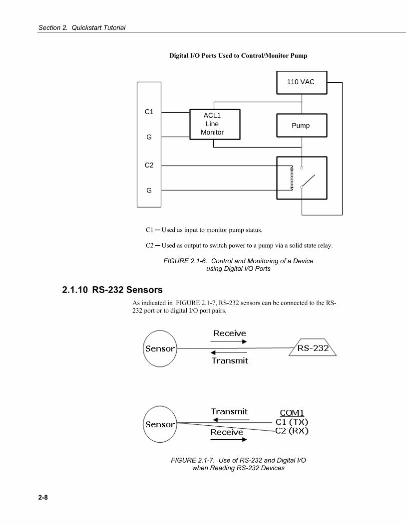
Section 2. Quickstart Tutorial
2-8
Digital I/O Ports Used to Control/Monitor Pump
110 VAC
Pump
ACL1Line
Monitor
C1
G
C2
G
CR10
C1 Used as input to monitor pump status.
C2 Used as output to switch power to a pump via a solid state relay.
FIGURE 2.1-6. Control and Monitoring of a Device using Digital I/O Ports
2.1.10 RS-232 Sensors As indicated in FIGURE 2.1-7, RS-232 sensors can be connected to the RS-232 port or to digital I/O port pairs.
FIGURE 2.1-7. Use of RS-232 and Digital I/O when Reading RS-232 Devices

Section 2. Quickstart Tutorial
2-9
2.1.11 Input Expansion Modules Modules are available from Campbell Scientific to expand the number of input and digital I/O ports on the CR1000. Appendix F.7 lists available modules.
2.2 Hands-on Exercise — Measuring a Thermocouple
This tutorial is a stepwise procedure for configuring a CR1000 to make a simple thermocouple measurement and send the resulting data to a PC. Discussions include programming, real-time data monitoring, collecting data, and viewing data. Principles discussed are applicable to all CR1000 applications.
2.2.1 Connections Connect power and RS-232 cables to the CR1000 as illustrated in FIGURE 2.2-1.
Compatible power supplies are discussed in Section 6 Power Supply. When connecting power to the CR1000, first remove the green power connector from the wiring panel. Insert the positive 12 V lead into the terminal labeled “12V”, and the ground lead into the terminal labeled “G”. Confirm the polarity of the wires before re-inserting the connector.
Connect the serial cable supplied with the CR1000 between the port labeled “RS-232” on the CR1000 and the serial (COM) port on the computer. For computers with USB ports, a USB-to-serial adaptor is required.
FIGURE 2.2-1. Power and RS-232 Connections
RS-232 Connection
On/Off Switch
Green 12 VDC Power Connection (Observe Polarity!)
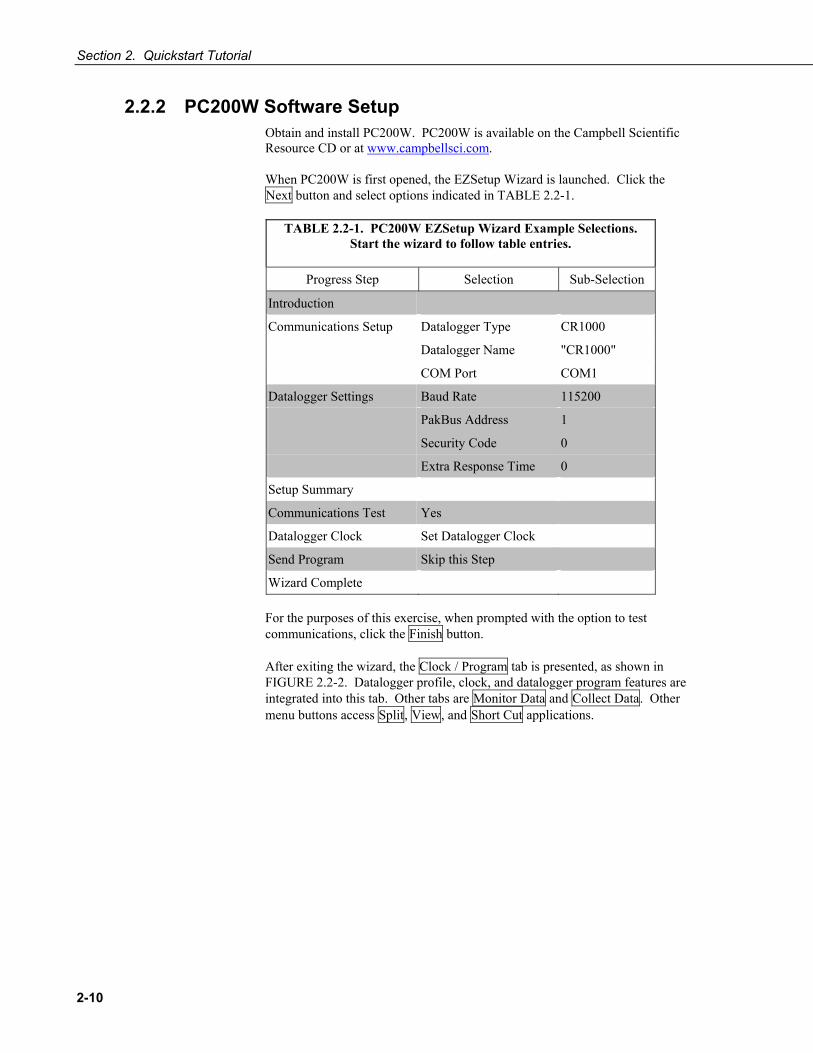
Section 2. Quickstart Tutorial
2-10
2.2.2 PC200W Software Setup Obtain and install PC200W. PC200W is available on the Campbell Scientific Resource CD or at www.campbellsci.com.
When PC200W is first opened, the EZSetup Wizard is launched. Click the Next button and select options indicated in TABLE 2.2-1.
TABLE 2.2-1. PC200W EZSetup Wizard Example Selections. Start the wizard to follow table entries.
Progress Step Selection Sub-Selection
Introduction
Communications Setup Datalogger Type CR1000
Datalogger Name "CR1000"
COM Port COM1
Datalogger Settings Baud Rate 115200
PakBus Address 1
Security Code 0
Extra Response Time 0
Setup Summary
Communications Test Yes
Datalogger Clock Set Datalogger Clock
Send Program Skip this Step
Wizard Complete For the purposes of this exercise, when prompted with the option to test communications, click the Finish button.
After exiting the wizard, the Clock / Program tab is presented, as shown in FIGURE 2.2-2. Datalogger profile, clock, and datalogger program features are integrated into this tab. Other tabs are Monitor Data and Collect Data. Other menu buttons access Split, View, and Short Cut applications.
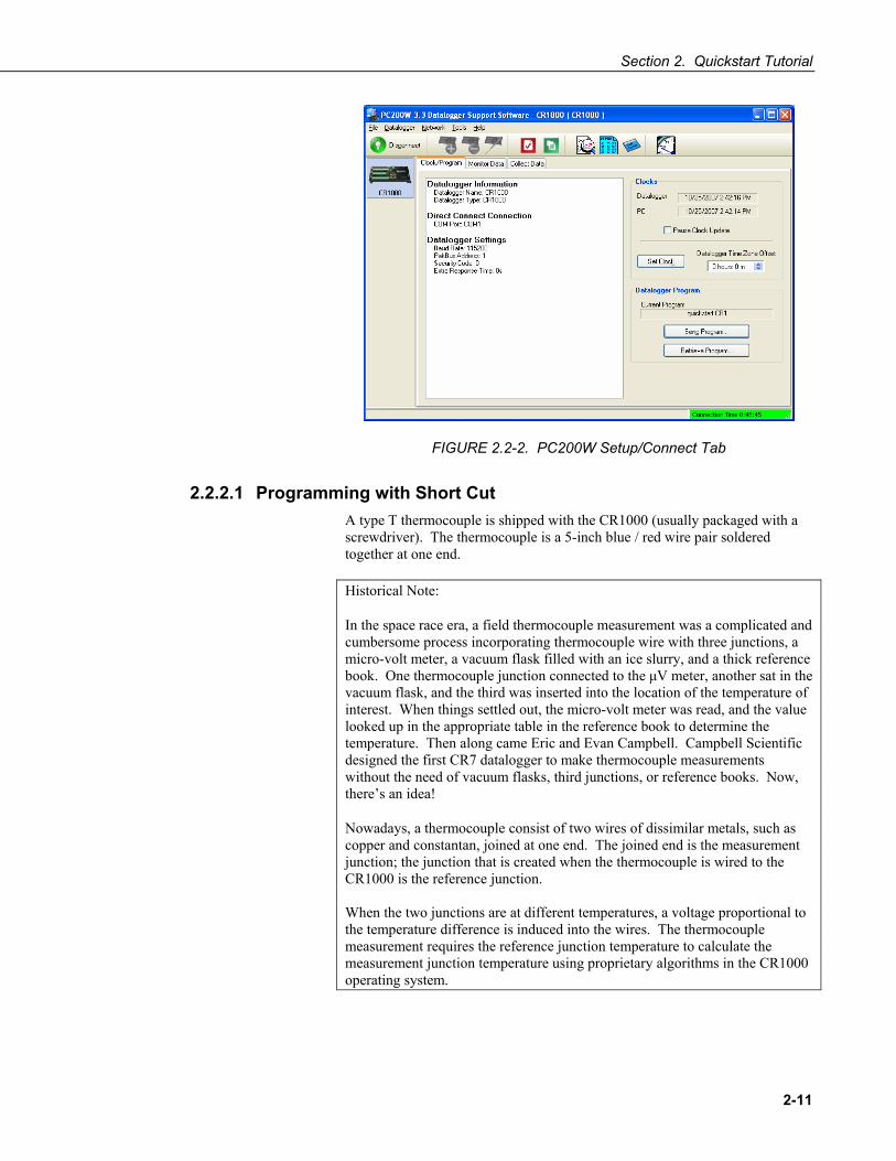
Section 2. Quickstart Tutorial
2-11
FIGURE 2.2-2. PC200W Setup/Connect Tab
2.2.2.1 Programming with Short Cut A type T thermocouple is shipped with the CR1000 (usually packaged with a screwdriver). The thermocouple is a 5-inch blue / red wire pair soldered together at one end.
Historical Note:
In the space race era, a field thermocouple measurement was a complicated and cumbersome process incorporating thermocouple wire with three junctions, a micro-volt meter, a vacuum flask filled with an ice slurry, and a thick reference book. One thermocouple junction connected to the μV meter, another sat in the vacuum flask, and the third was inserted into the location of the temperature of interest. When things settled out, the micro-volt meter was read, and the value looked up in the appropriate table in the reference book to determine the temperature. Then along came Eric and Evan Campbell. Campbell Scientific designed the first CR7 datalogger to make thermocouple measurements without the need of vacuum flasks, third junctions, or reference books. Now, there’s an idea!
Nowadays, a thermocouple consist of two wires of dissimilar metals, such as copper and constantan, joined at one end. The joined end is the measurement junction; the junction that is created when the thermocouple is wired to the CR1000 is the reference junction. When the two junctions are at different temperatures, a voltage proportional to the temperature difference is induced into the wires. The thermocouple measurement requires the reference junction temperature to calculate the measurement junction temperature using proprietary algorithms in the CR1000 operating system.

Section 2. Quickstart Tutorial
2-12
Short Cut Programming Objectives:
At one second intervals, measure CR1000 power supply voltage and CR1000 wiring panel temperature. Measure air temperature in °C with the thermocouple. Store one-minute average battery voltage, panel temperature, and thermocouple temperature.
Procedure:
Click on the Short Cut button, shown in FIGURE 2.2-3, in the upper right of the PC200W window.
FIGURE 2.2-3. Short Cut “1. New/Open” Page
Use Help in conjunction with the steps outlined below:
Step 1: Open a new or existing file.
The first time Short Cut is run, a prompt asks for a choice of “AC Noise Rejection.” If the CR1000 is used in the United States, choose “60 Hz”; many other countries use “50 Hz” power mains systems. A second prompt asks for a choice of “Sensor Support.” Choose “Campbell Scientific, Inc.”
On the “1. New/Open” page, click [New Program]. Use the drop-down list box that appears to select CR1000. Click [OK]. Enter a 1 second Scan Interval and click [OK]. Click on [Next>] to progress to “2. Sensors” page.
Step 2: Select sensors to be measured.
Settings | Sensor Support allows selection of alternate sensor sets.
NOTE
NOTE

Section 2. Quickstart Tutorial
2-13
Sensors page is divided into two sections: Available Sensors and Selected table, as shown in FIGURE 2.2-4. Sensors desired are chosen from the available sensors tree.
On the Available Sensors tree, open the Sensors folder to show several sub-folders. Each sub-folder includes a class of sensors. Open the Temperature sub-folder to display available temperature sensors.
Double click on the Wiring Panel Temperature sensor to add it to the selected sensors table. Click OK on the next screen to accept the PTemp_C label.
Double click on the Type T Thermocouple. Change the number of sensors to add to “1” and click OK. On the next screen, make sure Ptemp_C is selected for the Reference Temperature Measurement, and click OK to accept the Temp_C label.
FIGURE 2.2-4. Short Cut Sensors Page
Click on Wiring Diagram to view the sensor wiring diagram, as shown in FIGURE 2.2-5. Wire the Type T Thermocouple (provided) to the CR1000 as shown on the diagram. Click on 3. Outputs to continue with Step 3.

Section 2. Quickstart Tutorial
2-14
FIGURE 2.2-5. Short Cut Wiring Diagram
Step 3: Data Storage Output Processing.
The Outputs page has a list of Selected Sensors to the left, and data storage Tables to the right as shown in FIGURE 2.2-6. Two Tables, Table1 and Table2, are available by default. Both Tables have a Store Every field and a list box to select time units. These are used to set the interval at which data is stored.
FIGURE 2.2-6. Short Cut Outputs Page

Section 2. Quickstart Tutorial
2-15
This exercise calls for one-minute data storage processing, so only one data table is needed. To remove Table2, click on Table2 tab to activate it, and click the Delete Table button.
The Table Name field is the name that is used for the Table in which data are stored. Change the default name of Table1 to OneMin, and change the interval to 1 minute.
To add a measurement to data storage Table OneMin, highlight a measurement under Selected Sensors (Batt_Volt) and click the appropriate processing button (Average). Select the Batt_Volt, PTemp_C, and Temp_C measurements and apply Average processing to each to add them to the OneMin Table measurements.
Click Finish and name the file “Quickstart” to continue with Step 4 and complete the program.
Step 4: Program Finish.
As shown in FIGURE 2.2-7, any errors the compiler may have detected are displayed, along with the names of the files that were created. The file Quickstart.CR1 is the program file that is to be sent to the CR1000. Quickstart.def is a summary of the sensor wiring and measurement labels. Click the Summary tab and / or Print buttons to view and print the summaries. Click the X button to exit the Short Cut window.
FIGURE 2.2-7. Short Cut Finish Page

Section 2. Quickstart Tutorial
2-16
2.2.2.2 Connecting to the Datalogger From the PC200W Clock / Program tab, click the Connect / Disconnect button, which is indicated in FIGURE 2.2-8, to establish communications with the CR1000. When communications have been established, the text on the button will change to Disconnect.
FIGURE 2.2-8. Using PC200W Connect Button to Establish Communication Link
2.2.2.3 Synchronizing the Clocks Click the Set Clock button to synchronize the datalogger’s clock with the computer’s clock.
2.2.2.4 Sending the Program Click the Send Program button. Navigate to the C:\CampbellSci\SCWin folder and select the file QED.CR1 and click the Open button. A progress bar is displayed, followed by a message that the program was successfully sent.
Connect Button
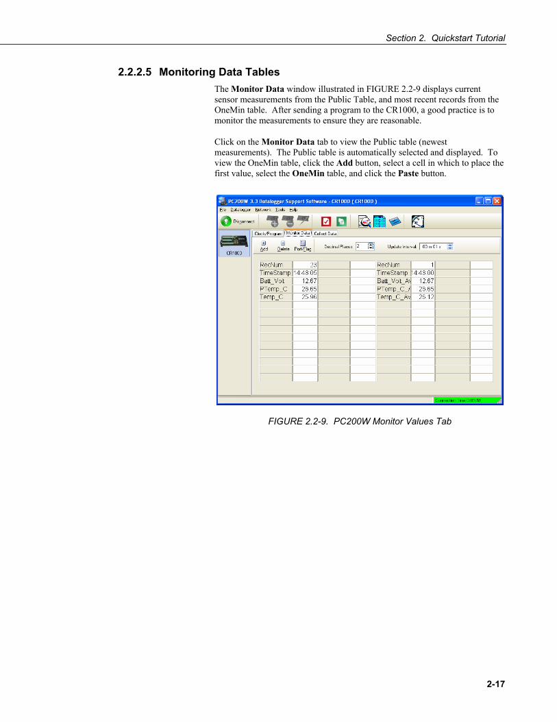
Section 2. Quickstart Tutorial
2-17
2.2.2.5 Monitoring Data Tables The Monitor Data window illustrated in FIGURE 2.2-9 displays current sensor measurements from the Public Table, and most recent records from the OneMin table. After sending a program to the CR1000, a good practice is to monitor the measurements to ensure they are reasonable.
Click on the Monitor Data tab to view the Public table (newest measurements). The Public table is automatically selected and displayed. To view the OneMin table, click the Add button, select a cell in which to place the first value, select the OneMin table, and click the Paste button.
FIGURE 2.2-9. PC200W Monitor Values Tab

Section 2. Quickstart Tutorial
2-18
2.2.2.6 Collecting Data Click on the Collect Data tab (FIGURE 2.2-10). From the Collect Data window, choose what data to collect, and where to store the collected data.
Click on the OneMin table, with the option New data from datalogger selected. Click the Collect button and a dialog box appears, prompting for a file name. Click the Save button to use the default file name CR1000_OneMin.dat. A progress bar, followed by the message Collection Complete is displayed.
FIGURE 2.2-10. PC200W Collect Data Tab

Section 2. Quickstart Tutorial
2-19
2.2.2.7 Viewing Data To view the collected data, click on the View button (located in the upper right-central portion of the main screen). Options are accessed by using the menus or by selecting the toolbar icons. Move and hold the mouse over a toolbar icon for a few seconds for a brief description of that icon's function.
To open a data file, click the Open file icon (FIGURE 2.2-11), and double click on the file CR1000_OneMin.dat in the PC200W folder. Click the Expand Tabs icon to display the data in columns with column headings. To graph thermocouple temperature, click on the data column with the heading Temp_C, then click the Show Graph, 1 Y axis icon on the toolbar.
FIGURE 2.2-11. PC200W View Data Utility
Close the graph and view screens, and close PC200W.
Open file Expand tabs Show graph

Section 2. Quickstart Tutorial
2-20

3-1
Section 3. Overview 3.1 CR1000 Overview
The CR1000 Datalogger is a precision instrument designed for demanding low-power measurement applications. CPU, analog and digital inputs, analog and digital outputs, and memory are controlled by the operating system in conjunction with the user program. The user program is written in CRBASIC, a programming language that includes data processing and analysis routines and a standard BASIC instruction set. Campbell Scientific’s datalogger support software facilitates program generation, editing, data retrieval, and real-time data monitoring (see Section 13 Support Software).
FIGURE 3.1-1 illustrates principal features of common CR1000-based data acquisition systems.
FIGURE 3.1-1. Principal Features of CR1000 Data Acquisition Systems
As a simple concept, the CR1000 is a multimeter with memory and timekeeping. It is one part of a data acquisition system. To acquire quality data, suitable sensors and reliable telecommunications devices are also required.
Sensors transduce phenomena into measurable electrical forms, outputting voltage, current, resistance, pulses, or state changes. The CR1000, sometimes with the assistance of various peripheral devices, can measure nearly all electronic sensors.

Section 3. Overview
3-2
The CR1000 measures analog voltage and pulse signals, representing the magnitudes numerically. Numeric values are scaled to the unit of measure such as millivolts and pulses, or in user specified engineering units such as wind direction and wind speed. Measurements can be processed through calculations or statistical operations and stored in memory awaiting transfer to a PC via external storage or telecommunications.
The CR1000 has the option of evaluating programmed instructions sequentially, or in pipeline mode, wherein the CR1000 decides the order of instruction execution.
3.1.1 Sensor Support Read More! See Section 4 Sensor Support.
The following sensor types are supported by the CR1000 datalogger. Refer to Appendix F.1 for information on sensors available from Campbell Scientific.
Analog voltage Analog current (with a shunt resistor) Thermocouples Resistive bridges Pulse output Period output Frequency output Serial smart sensors SDI-12 sensors
A library of sensor manuals and application notes are available at www.campbellsci.com to assist in measuring many sensor types. Consult with a Campbell Scientific applications engineer for assistance in measuring unfamiliar sensors.
3.1.2 Input / Output Interface: The Wiring Panel The wiring panel of the CR1000 is the interface to all CR1000 functions. Most CR1000 functions are best introduced by reviewing features of the CR1000 wiring panel. FIGURE 2.1-1 illustrates the wiring panel and some CR1000 functions accessed through it.
Read More! Expansion accessories increase the input / output capabilities of the wiring panel. Read Section 5 Measurement and Control Peripherals for more information.
3.1.2.1 Measurement Inputs Measurements require a physical connection with a sensor at an input channel and CRBASIC programming to instruct the CR1000 how to make, process, and store the measurement. The CR1000 wiring panel has the following input channels:
Analog Voltage: 16 channels (Diff 1 - 8 / SE 1 - 16) configurable as 8 differential or 16 single-ended inputs.
• Input voltage range: -5000 mV to +5000 mV. • Measurement resolution: 0.67 μV to 1333 μV

Section 3. Overview
3-3
Period Average: 16 channels (SE 1 -16) • Input voltage range: -2500 mV to +2500 mV. • Maximum frequency: 200 kHz
Technical Note Pulse Count vs. Period Average
Pulse count and period average measurements both can be used to measure sensors that output frequency. Yet pulse count and period average measurement methods are quite different, resulting in different characteristics for each type. Pulse count measurements use dedicated counter hardware that is always monitoring the input signal, even when the datalogger goes to sleep mode between scans. Period average measurements utilize multiplexed voltage measurement hardware and so only monitor the input signal during the execution of a period average instruction. Consequently, pulse count measurement intervals can generally be made much longer than period average measurement intervals, which is advantageous if trying to minimize the effects of low-frequency noise. Pulse count measurements are not appropriate for sensors that are powered down between scans, whereas period average measurements work well as they can be placed in the scan so as to execute only when the sensor is powered up and outputting valid frequency information.
Period average measurements utilize a high-frequency digital clock to measure time differences between signal transitions, whereas pulse count measurements simply accumulate the number of counts. As a result, period average measurements offer much better frequency resolution per measurement interval, as compared to pulse count measurements. The frequency resolution of pulse count measurements can be improved by extending the measurement interval by increasing the scan interval and by averaging.
Pulse: 2 channels (P1 - P2) configurable for counts or frequency of the following signal types: • High level 5V square waves • Switch closures • Low-level A/C sine waves
Digital I/O: 8 channels (C1 - C8) configurable for serial input, SDM, SDI-12, state, frequency, pulses, edge counting and edge timing. • C1 - C8: state, frequency, pulse, edge counting and edge timing
measurements. • C1 - C3: Synchronous Devices for Measurement (SDM) input /
output. • C1, C3, C5, C7: SDI-12 input / output. • C1 - C2, C3 - C4, C5 - C6, C7 - C8: serial communication input /
output.
9Pin RS-232: 1 port (Computer RS-232) configurable for serial input.
Refer to Appendicies F.7, F.9, F.10 for information on available input expansion modules.

Section 3. Overview
3-4
3.1.2.2 Voltage Outputs The CR1000 supplies precision voltage excitation for resistive measurements through the following output channels:
Switched Analog Voltage Output (Excitation): 3 channels (Vx/VX1 (VX1 (EX1)) – Vx/VX3 (EX3)) for precise voltage excitation ranging from -2500 mV to +2500 mV. Each channel will source up to 25 mA. The CR1000 can be used as a PLC (programmable logic controller). Utilizing peripheral relays and analog output devices, the CR1000 can manage binary and variable control devices through the following output channels:
Read More! See Section 5.4 Control Output.
Continuous Analog Voltage Output: available by adding a peripheral analog output device available from Campbell Scientific..
Digital I/O: 8 channels (C1 - C8) configurable for pulse output duration.
Switched 12 Volts (SW-12): controls (switches on / off ) primary battery voltage under program control for use with external devices, such as humidity sensors, requiring controlled 12 V. SW-12 can source up to 600 mA.
Refer to Appendix F.8 for information on available output expansion modules.
3.1.2.3 Grounding Terminals Read More! See Section 7 Grounding.
Proper grounding will lend stability and protection to a data acquisition system. It is the easiest and least expensive insurance against data loss and the most neglected. The following terminals are provided for connection of sensor and datalogger grounding:
Signal Grounds: 12 terminals ( ) used as reference for single-ended analog inputs, pulse inputs, excitation returns, and as a ground for sensor shield wires. Signal returns for pulse inputs should use terminals located next to pulse inputs.
Power Grounds: 6 terminals (G) used as returns for 5V, SW12, 12V, and C1-C8 outputs. Use of G grounds for these outputs minimizes potentially large current flow through the analog voltage measurement section of the wiring panel, which can cause single-ended voltage measurement errors.
Ground Lug: 1 terminal ( ), the large ground lug is used to connect a heavy gage wire to earth ground. A good earth connection is necessary to secure the ground potential of the datalogger and shunt transients away from electronics. Minimum 14 AWG wire is recommended.

Section 3. Overview
3-5
3.1.2.4 Power Terminals Read More! See Section 6 Power Supply.
Power In
Power Supply: One green plug (POWER IN): for connecting power from an external power source to the CR1000. These are the only terminals used to input battery power; other 12V terminals and the SW-12 terminal are output only terminals for supplying power to other devices. Review power requirements and power supply options in Section 6 CR1000 Power Supply before connecting power.
Refer to Appendix F.3 for information on available power supplies.
Power Out
Peripheral 12 V Power Source: 2 terminals (12V) and associated grounds (G) supply power to sensors and peripheral devices requiring nominal 12 VDC. This supply may drop as low as 9.6 VDC before datalogger operation stops. Precautions should be taken to minimize the occurrence of data from underpowered sensors.
Peripheral 5 Volt Power Source: 1 terminal (5V) and associated ground (G) supply power to sensors and peripheral devices requiring regulated 5 VDC.
3.1.2.5 Communications Ports Read More! See Section 13 Telecommunication and Data Retrieval and Section 14 PakBus Overview.
The CR1000 is equipped with several communications ports. Communication ports allow the CR1000 to communicate with other computing devices, such as a PC, or with other Campbell Scientific dataloggers.
RS-232 communications normally operate well up to a transmission cable capacitance of 2500 picofarads, or approximately 50 feet of commonly available serial cable.
9-pin RS-232: 1 DCE port for communicating with a PC through the supplied serial cable, serial sensors, or through 3rd party serial telecommunications devices. Acts as a DTE device with a null-modem cable.
Read More! See Appendix C Serial Port Pin-outs.
9-pin CS I/O port: 1 port for communicating through Campbell Scientific telecommunications peripherals. Approved CS I/O telecommunication interfaces are listed in Appendix F.10 Serial Input / Output Peripherals.
2-pin RS-232: 4 ports configurable from Control I/O ports for communication with serial sensors or other Campbell Scientific dataloggers.
NOTE

Section 3. Overview
3-6
Peripheral: 1 port for use with some Campbell Scientific CF memory card modules and IP network link hardware. See Section 10.2 for CF card precautions.
The 9-pin RS-232 port is not isolated. “Isolation” means electrically isolated, often by means of optical (light operated) isolation components, from the communications node at the other end of the connection. Optical isolation prevents some electrical problems such as ground looping, which can cause significant errors in single-ended measurements. If optical isolation is required, Campbell Scientific offers an optically isolated RS-232 to CS I/O interface as a CR1000 accessory. Refer to Appendix F.10 for model information.
3.1.3 Power Requirements Read More! See Section 6 Power Supply.
The CR1000 operates from a DC power supply with voltage ranging from 9.6 to 16 V, and is internally protected against accidental polarity reversal. The CR1000 has modest input power requirements. In low power applications, it can operate for several months on non-rechargeable batteries. Power systems for longer-term remote applications typically consist of a charging source, a charge controller, and a rechargeable battery. When AC line power is available, an AC/AC or AC/DC wall adapter, a charge controller, and a rechargeable battery can be used to construct a UPS (uninterruptible power supply). Contact a Campbell Scientific applications engineer for assistance in acquiring the items necessary to construct a UPS.
Applications requiring higher current requirements, such as satellite or cellular phone communications, should be evaluated by means of a power budget with a knowledge of the factors required by a robust power system. Contact a Campbell Scientific applications engineer if assistance is required in evaluating power supply requirements.
Common power devices are listed below. Refer to Appendix F.3 for specific model numbers of approved power supplies:
Batteries Alkaline D-cell - 1.5 V/cell Rechargeable Lead-Acid battery
Charge Sources Solar Panels Wind Generators AC/AC or AC/DC wall adapters
3.1.4 Programming: Firmware and User Programs The CR1000 is a highly programmable instrument, adaptable to the most demanding measurement and telecommunications requirements.
NOTE

Section 3. Overview
3-7
3.1.4.1 Firmware: OS and Settings Read More! See Section 8 CR1000 Configuration.
Firmware consists of the operating system (OS) and durable configuration settings. OS and settings remain intact when power is cycled.
Good News! The CR1000 is shipped factory ready with all settings and firmware necessary to communicate with a PC via RS-232 and to accept and execute user application programs. OS upgrades are occasionally made available at www.campbellsci.com.
For more complex applications, some settings may need adjustment. Adjustments are accomplished with CSI’s DevConfig Software (Section 8.1 DevConfig), CR1000KD Keyboard Display (Section 17 CR1000KD: Using the Keyboard Display), or through datalogger support software (see Section 16 Support Software).
OS files are sent to the CR1000 with DevConfig, through the program Send button in datalogger support software, or with a CF card. When the OS is sent via DevConfig, most settings are cleared, whereas, when sent via datalogger support software, most settings are retained.
3.1.4.2 User Programming Read More! See Section 9 CR1000 Programming and Section 10 CRBASIC Programming Instructions and CRBASIC help for more programming assistance.
A CRBASIC program directs the CR1000 how and when sensors are to be measured, calculations made, and data stored. A program is created on a PC and sent to the CR1000. The CR1000 can store a number of programs in memory, but only one program is active at a given time. Three Campbell Scientific software applications, Short Cut, CRBASIC Editor, and Transformer Utility create CR1000 programs.
1. Short Cut creates a datalogger program and wiring diagram in four easy steps. It supports most sensors sold by Campbell Scientific and is recommended for creating simple programs to measure sensors and store data.
2. Programs generated by Short Cut are easily imported into CRBASIC Editor for additional editing. For complex applications, experienced programmers often create essential measurement and data storage code with Short Cut, then edit the code with CRBASIC Editor. Note that once a Short Cut generated program has been edited with CRBASIC Editor, it can no longer be modified with Short Cut.
3. Transformer utility converts CR10X code to CR1000 code, which can then be imported into CRBASIC Editor. Because of differences in syntax, not all CR10X code is fully convertible. Transformer is included with PC400 and LoggerNet software and is typically accessed from Windows Explorer in C:\Campbellsci\Loggernet or C:\Campbellsci\PC400 folders, or from Windows Desktop: Start | All Programs | LoggerNet | Utilities | Transformer.

Section 3. Overview
3-8
3.1.5 Memory and Data Storage Read More! See Section 12 Memory and Data Storage.
The CR1000 has 2 MBytes Flash EEPROM used to store the operating system. Another 512 K of Flash stores configuration settings. Beginning with CR1000 serial number 11832, 4 MBytes of SRAM are available for program storage (32K), operating system use, and data storage. The size of available memory is posted in the status table (Appendix A). Additional data storage is optionally available by using a CompactFlash® card with a CompactFlash® module listed in Appendix F.14.
Program storage memory is usually partitioned as a single drive, CPU:. CC640 camera applications require storage of image files on a USR: virtual drive, which is partitioned from the CR1000 data storage memory.
3.1.6 Communications Read More! See Section 13 Telecommunications and Data Retrieval.
The CR1000 communicates with external devices to receive programs, send data, or act in concert with a network. The primary communication protocol is PakBus. Modbus and DNP3 communication protocols are also supported. Refer to Appendix F.12 for information on available communications devices.
3.1.6.1 PakBus Read More! See Section 14 PakBus Overview.
The CR1000 communicates with Campbell Scientific support software, telecommunication peripherals, and other dataloggers via PakBus, a proprietary network communications protocol. PakBus is a protocol similar in concept to IP (Internet protocol). By using signatured data packets, PakBus increases the number of communications and networking options available to the CR1000. Communication can occur via RS-232, CS I/O, or digital I/O ports.
Advantages of PakBus:
• Simultaneous communication between the CR1000 and other devices.
• Peer-to-peer communication — no PC required.
• Other PakBus dataloggers can be used as “sensors” to consolidate all data into one CR1000.
• Routing – the CR1000 can act as a router, passing on messages intended for another logger. PakBus supports automatic route detection and selection.
• Short distance networks with no extra hardware – A CR1000 can talk to another CR1000 over distances up to 30 feet by connecting transmit, receive and ground wires between the dataloggers. PC communications

Section 3. Overview
3-9
with a PakBus datalogger via the CS I/O port, over phone modem or radio, can be routed to other PakBus dataloggers.
• Datalogger to datalogger communications – special CRBASIC instructions simplify transferring data between dataloggers for distributed decision making or control.
• In a PakBus network, each datalogger is set to a unique address before installed in the network. Default PakBus address is 1. To communicate with the CR1000, the datalogger support software (see Section 13) must know the CR1000’s PakBus address. The PakBus address is changed using the CR1000KD Keyboard Display, DevConfig software, CR1000 status table, or PakBus Graph software.
3.1.6.2 Modbus Read More! See Section 15.2 Modbus.
The CR1000 supports Modbus Master and Modbus Slave communication for inclusion in Modbus SCADA networks.
3.1.6.3 DNP3 Communication Read More! See Section 15.1 DNP3.
The CR1000 supports DNP3 Slave communication for inclusion in DNP3 SCADA networks.
3.1.6.4 Keyboard Display Read More! See Section 17 CR1000KD: Using the Keyboard Display.
The CR1000KD Keyboard Display is a powerful tool for field use. It allows complete access to most datalogger tables and function, allowing the user to monitor, make modifications, and troubleshoot a datalogger installation conveniently and in most weather conditions.
3.1.6.4.1 Custom Menus
Read More! To implement custom menus, see CRBASIC Help for the DisplayMenu() instruction.
CRBASIC programming in the CR1000 facilitates creation of custom menus for the CR1000KD Keyboard Display.
FIGURE 3.1-2 shows windows from a simple CR1000KD custom menu named “DataView”. “DataView” appears as the main menu on the CR1000KD. DataView has menu item, “Counter”, and submenus “PanelTemps”, “TCTemps”, and “System Menu”. “Counter” allows selection of 1 of 4 values. Each submenu displays two values from CR1000 memory. PanelTemps shows the CR1000 wiring panel temperature at each scan, and the one minute sample of panel temperature. TCTemps displays two thermocouple temperatures.

Section 3. Overview
3-10
PanelTemps: Scan |23.4960 Final Stg |23.5000
TCTemps: TC_Temp_1 |29.4355 TC_Temp_2 |32.3133
Data Run/Stop Program File Ports and Status Configure, Settings
DataView PanelTemps > Counter |0.00000 TCTemps > System Menu >
FIGURE 3.1-2. CR1000KD Custom Menu Example
3.1.7 Security CR1000 applications may include collection of sensitive data, operation of critical systems, or networks accessible by many individuals. CR1000 security provides means by which partial or complete lock-out can be accomplished in the CRBASIC program code.
Up to three levels of security can be set in the datalogger. Level 1 must be set before Level 2. Level 2 must be set before Level 3. If a level is set to 0, any level greater than it will also be set to 0 (e.g., if Level 2 is 0, Level 3 is 0). Valid security codes are 1 through 65535 (0 is no security). Each level must have a unique code. If security is set to a negative code in the CR1000, a positive code must be entered to unlock the CR1000. That positive code = 65536 + (negative security code). For example, a security code of -1111 must be entered as 64425 to unlock the CR1000.
Security can be enabled using DevConfig, the CR1000KD, Status Table, or the SetSecurity() instruction.
Functions affected by each level of security are:
Level 1: collecting data, setting the clock, and setting variables in the Public table are unrestricted. Enter level 1 password to change or retrieve the datalogger program or set variables in the Status table.
Level 2: collecting data are unrestricted. Enter level 2 password to set the clock or change variables in the public table. Enter level 1 password to change the datalogger program or non-read-only postings in the status table.
Level 3: Enter level 3 password to collect data. Enter level 2 password to collect data, set public variable and set the clock. Enter level 1 password to open all datalogger functions to unrestricted use.
Security can be bypassed at the datalogger using a CR1000KD. Pressing and holding the "Del" key while powering up a CR1000 will cause it to abort

Section 3. Overview
3-11
loading a program and provide a two minute window to either review or disable security codes in the settings editor (not status table) with the CR1000KD. CR1000KD security bypass does not allow telecommunications access without first correcting the security code.
3.1.8 Care and Maintenance Read More! See Section 18 Care and Maintenance.
With reasonable care, the CR1000 should give many years of reliable service.
3.1.8.1 Protection from Water The CR1000 and most of its peripherals must be protected from moisture. Moisture in the electronics will seriously damage, and probably render un-repairable, the CR1000. Water can come from flooding or sprinkler irrigation, but most often comes as condensation. Protecting from water is as easy as placing the CR1000 in a weather tight enclosure with desiccant. The CR1000 is shipped with desiccant to reduce humidity. Desiccant should be changed periodically. Do not completely seal the enclosure if lead acid batteries are present; hydrogen gas generated by the batteries may build up to an explosive concentration. Refer to Appendix F.4 for information on available weather tight enclosures.
3.1.8.2 Protection from Voltage Transients Read More! See Section 7 Grounding.
The CR1000 must be grounded to minimize the risk of damage by voltage transients associated with power surges and lightning induced transients. Earth grounding is required to form a complete circuit for voltage clamping devices internal to the CR1000. Refer to Appendix F.13 for information on available surge protection devices.
3.1.8.3 Calibration Read More! See 4.2.8 Self-Calibration.
The CR1000 uses an internal voltage reference to routinely calibrate itself. To maintain electrical specifications, Campbell Scientific recommends factory recalibration every two years. For calibration services, contact Campbell Scientific to obtain a Return Materials Authorization (RMA) prior to shipping.
3.1.8.4 Internal Battery
Misuse of the lithium battery or installing it improperly can cause severe injury. Fire, explosion, and severe burn hazard! Do not recharge, disassemble, heat above 100°C (212°F), solder directly to the cell, incinerate, nor expose contents to water. Dispose of spent lithium batteries properly.
The CR1000 contains a lithium battery that operates the clock and SRAM when the CR1000 is not externally powered. In a CR1000 stored at room temperature, the lithium battery should last approximately 10 years (less at
CAUTION

Section 3. Overview
3-12
temperature extremes). In installations where the CR1000 is powered most of the time, the lithium cell should last much longer. Lithium battery voltage can be monitored from the CR1000 Status Table. Operating range of the battery is 2.7 to 3.6 VDC. Replace the battery as directed in Section 18.4 when the voltage is below 2.7 VDC.
3.2 PC Support Software Read More! See Section 16 Support Software.
Several datalogger support software products for Windows are available. Software for datalogger setup and simple applications, PC200W and Short Cut, are available at no cost at 7www.campbellsci.com. For more complex programming, telecommunications, networking, and reporting features, full-featured products are available from Campbell Scientific.
1. PC200W Starter Software is available at no charge at 7www.campbellsci.com. It supports a transparent RS-232 connection between PC and CR1000, and includes Short Cut for creating CR1000 programs. Tools for setting the datalogger clock, sending programs, monitoring sensors, and on-site viewing and collection of data are also included.
2. PC400 supports a variety of telecommunication options, manual data collection, and data monitoring displays. Short Cut, CRBASIC Editor, and Transformer Utility are included for creating CR1000 programs. PC400 does not support complex communication options, such as phone-to-RF, PakBus® routing, or scheduled data collection.
3. LoggerNet supports combined telecommunication options, customized data monitoring displays, and scheduled data collection. It includes Short Cut, CRBASIC Editor, and Transformer Utility programs for creating CR1000 programs. It also includes tools for configuring, trouble-shooting, and managing datalogger networks. LoggerNet Admin and LoggerNet Remote are also available for more demanding applications.

Section 3. Overview
3-13
3.3 Specifications

Section 3. Overview
3-14

4-1
Section 4. Sensor Support Several features give the CR1000 the flexibility to measure many sensor types. Contact a Campbell Scientific applications engineer if assistance is required to assess sensor compatibility.
4.1 Powering Sensors Read More! See Section 6 Power Supply.
The CR1000 is a convenient source of power for sensors and peripherals requiring a 5 or 12 VDC source. It has two continuous 12 Volt terminals (12V), one program-controlled switched 12 Volt terminal (SW-12), and one continuous 5 Volt terminal (5V). SW-12, 12V, and 5V terminals limit current internally for protection against accidental short circuits. Voltage on the 12V and SW-12 terminals will change with the DC supply used to power the CR1000. The 5V terminal is internally regulated to within ±4%, which is typically not adequate accuracy for bridge sensor excitation. TABLE 4.1-1 shows the current limits of 12V and 5V. Greatly reduced output voltages associated with 12V, SW-12, and 5V due to current limiting may occur if the current limits given in TABLE 4.1-1 are exceeded.
4.1.1 Switched Precision (-2500 to +2500 mV) Three switched analog output (excitation) terminals (Vx/VX1 (VX1 (EX1)), Vx/VX2 (EX2), Vx/VX3 (EX3)) operate under program control. Check the accuracy specification of these channels in Section 3.3 to understand their limitations. Specifications are only applicable for loads not exceeding ±25 mA. CRBASIC instructions that control excitation channels include:
BrFull () BrFull6W () BrHalf () BrHalf3W () BrHalf4W () ExciteV ()
Excitation channels can be configured through the RevEx parameter of bridge instructions to provide a squarewave AC excitation for use with polarizing bridge sensors.
4.1.2 Continuous Regulated 5 Volt The 5V terminal is regulated and remains near 5 Volts (±4%) so long as the CR1000 supply voltage remains above 9.6 Volts. Measurement of 5V voltage output by the datalogger (by means of jumpering to an analog input) enables an accurate bridge measurement if 5V must be used for excitation.
4.1.3 Continuous Unregulated Nominal 12 Volt Voltage on the 12V terminals will change with CR1000 supply voltage.
NOTE

Section 4. Sensor Support
4-2
4.1.4 Switched Unregulated (Nominal 12 Volt) Voltage on the SW-12 terminal will change with CR1000 supply voltage. Two CRBASIC instructions, SW12 () and PortSet (), control the SW-12 terminal. Each is handled differently by the CR1000.
SW12 () is a processing task instruction. Use it when controlling power to SDI-12 and serial sensors, which use SDI12Recorder () or SerialIn () instructions respectively. CRBASIC programming using IF THEN constructs to control SW-12, such as cell phone control, should also use the SW12 () instruction.
PortSet () is a measurement task instruction. Use it when powering analog input sensors that need to be turned on just prior to measurement.
TABLE 4.1-1. Current Sourcing Limits
Terminals Vx/VX1 (VX1 (EX1)), Vx/VX2 (EX2), Vx/VX3 (EX3)
Current Source Limit ±25 mA Maximum
SW12 < 900 mA @ 20°C < 730 mA @ 40°C < 650 mA @ 50°C < 570 mA @ 60°C < 360 mA @ 85°C 12V + SW12 < 3.00 A @ 20°C < 2.49 A @ 40°C < 2.31 A @ 50°C < 2.04 A @ 60°C < 1.56 A @ 85°C 5V + CSI/O < 200 mA
4.2 Voltage Measurement The CR1000 measures single-ended (SE) and / or differential (Diff) voltage inputs. Single-ended measurements use CRBASIC instruction VoltSE (), which returns the voltage difference between a single input (x.x mV) and ground (0 mV). Differential measurements use CRBASIC instruction VoltDiff (), which returns the voltage difference (x.x - y.y) between a high input (x.x mV) and a low input (y.y mV).
Associated with differential measurements is common-mode voltage, defined as the average DC voltage common to both the high and low inputs [(VHi + VLo) / 2] associated with a differential measurement. The CR1000 incorporates a differential instrumentation amplifier on its measurement front-end. This amplifier processes the difference between the voltage inputs, while rejecting common-mode signals, as long as the common-mode signals are within the ±5000 mV common-mode input range of the amplifier. The amplifier cannot properly reject common-mode signals that fall outside of the
Section 4. Sensor Support
4-3
±5000 mV common-mode input range. See Section 16.2 for more information on common-mode range.
Two sets of numbers are assigned to analog channels. For differential measurements, analog channels are numbered 1 - 8. Each differential channel as two inputs: high (H) and low (L). For single-ended measurement, analog channels are numbered 1-16.
Sustained voltages in excess of ±16 V input to the analog channels will damage CR1000 circuitry.
4.2.1 Electronic “Noise”: VoltDiff() or VoltSE()? Read More! Consult the following Campbell Scientific White Papers for an in-depth treatment of the advantages of differential and single-ended measurements. Find these papers at www.campbellsci.com.
“Preventing and Attacking Measurement Noise Problems”
“Benefits of Input Reversal and Excitation Reversal for Voltage Measurements”
“Voltage Measurement Accuracy, Self-Calibration, and Ratiometric Measurements
Deciding whether a differential or single-ended measurement is appropriate for a particular sensor requires sorting through trade-offs of accuracy and precision, available measurement hardware, and fiscal constraints.
In broad terms, analog voltage is best measured differentially because these measurements include noise reduction features, listed below, not included in single-ended measurements.
• Passive Noise Rejection o No voltage reference offset o Common-mode noise rejection
• Rejects capacitively coupled noise
• Active Noise Rejection o Input reversal
• Review Section 4.2.4.1 Input and Excitation Reversal for details • Doubles input reversal signal integration time
Reasons for using single-ended measurements, however, include:
• Sensor is not designed for differential measurement. • Sensor number exceeds available differential channels.
Sensors with a high signal-to-noise ratio, such as a relative humidity sensor with a full scale output of 0 to 1000 mV, can normally be measured single-endedly without a significant reduction in accuracy or precision.
NOTE
NOTE

Section 4. Sensor Support
4-4
Sensors with low signal-to-noise ratio, such as thermocouples, should normally be measured differentially. However, if the measurement to be made does not require high accuracy or precision, such as thermocouples measuring brush fire temperatures, a single-ended measurement may be appropriate. If sensors require differential measurement, but adequate input channels are not available, an analog multiplexer should be acquired to expand differential input capacity. Refer to Appendix F.5 for information concerning available multiplexers.
4.2.2 Measurement Sequence The CR1000 measures analog voltage by integrating the input signal for a fixed duration, then holding the integrated value during the successive approximation analog-to-digital (A/D) conversion. The CR1000 can make and store measurements from up to 8 differential or 16 single-ended channels at the minimum scan rate of 10 ms (100 Hz) using the burst mode voltage measurement (Section 11.13). The maximum conversion rate is 2700 per second for measurements made on a single channel.
The timing of CR1000 measurements is precisely controlled. The measurement schedule is determined at compile time and loaded into memory. This schedule sets interrupts that drive the measurement task.
Using two different voltage measurement instructions with the same voltage range takes the same measurement time as using one instruction with two repetitions.
Historical Lesson: This is not the case with legacy CR10(X), 21X, CR23X, and CR7(X) dataloggers. Using multiple measurement “reps” in these dataloggers reduced overall measurement time.
Several parameters in CRBASIC voltage measurement instructions VoltDiff () and VoltSE () vary the sequence and timing of measurements. TABLE 4.2-1 lists these parameters.
TABLE 4.2-1. CRBASIC Parameters Varying Measurement Sequence and Timing
CRBASIC Parameter Description MeasOfs Correct ground offset on single-ended measurements. RevDiff Reverse high and low differential inputs. SettlingTime Sensor input settling time. Integ Duration of input signal integration. RevEx Reverse polarity of excitation voltage.
4.2.3 Voltage Range In general, a voltage measurement should use the smallest fixed input range that will accommodate the full scale output of the sensor being measured. This results in the best measurement accuracy and resolution. The CR1000 has six fixed input ranges for voltage measurements, along with an autorange option that enables the CR1000 to automatically determine the appropriate input voltage range for a given measurement. TABLE 4.2-2 describes the CR1000 input voltage range options along with the associated alphanumeric range codes.
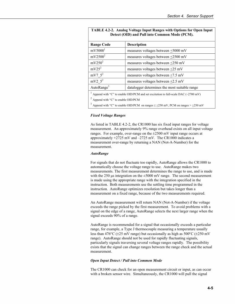
Section 4. Sensor Support
4-5
TABLE 4.2-2. Analog Voltage Input Ranges with Options for Open Input Detect (OID) and Pull into Common Mode (PCM).
Range Code Description mV50001 measures voltages between +5000 mV mV25002 measures voltages between +2500 mV mV2502 measures voltages between +250 mV mV252 measures voltages between +25 mV mV7_52 measures voltages between +7.5 mV mV2_52 measures voltages between +2.5 mV AutoRange3 datalogger determines the most suitable range 1 Append with “C” to enable OID/PCM and set excitation to full-scale DAC (~2700 mV) 2 Append with “C” to enable OID/PCM 3 Append with “C” to enable OID/PCM on ranges ≤ +250 mV, PCM on ranges > +250 mV Fixed Voltage Ranges
As listed in TABLE 4.2-2, the CR1000 has six fixed input ranges for voltage measurement. An approximately 9% range overhead exists on all input voltage ranges. For example, over-range on the ±2500 mV input range occurs at approximately +2725 mV and –2725 mV. The CR1000 indicates a measurement over-range by returning a NAN (Not-A-Number) for the measurement.
AutoRange
For signals that do not fluctuate too rapidly, AutoRange allows the CR1000 to automatically choose the voltage range to use. AutoRange makes two measurements. The first measurement determines the range to use, and is made with the 250 μs integration on the ±5000 mV range. The second measurement is made using the appropriate range with the integration specified in the instruction. Both measurements use the settling time programmed in the instruction. AutoRange optimizes resolution but takes longer than a measurement on a fixed range, because of the two measurements required.
An AutoRange measurement will return NAN (Not-A-Number) if the voltage exceeds the range picked by the first measurement. To avoid problems with a signal on the edge of a range, AutoRange selects the next larger range when the signal exceeds 90% of a range.
AutoRange is recommended for a signal that occasionally exceeds a particular range, for example, a Type J thermocouple measuring a temperature usually less than 476°C (±25 mV range) but occasionally as high as 500°C (±250 mV range). AutoRange should not be used for rapidly fluctuating signals, particularly signals traversing several voltage ranges rapidly. The possibility exists that the signal can change ranges between the range check and the actual measurement.
Open Input Detect / Pull into Common Mode
The CR1000 can check for an open measurement circuit or input, as can occur with a broken sensor wire. Simultaneously, the CR1000 will pull the signal
Section 4. Sensor Support
4-6
into common mode range. Range codes ending with “C” enable these features. Refer to TABLE 4.2-2 for limitations.
Open input detect works by connecting the voltage input to a 300 mV internal source for 50 µs. A differential voltage input has the high side connected to 300 mV and the low side connected to ground. After disconnecting, the input is allowed to settle, and the voltage measurement is made. If the sensor is open (inputs not connected but “floating”) the input capacitor will remain floating near the voltage it was previously connected to; a measurement on the ±2.5 mV, ±7.5 mV, ±25 mV, or the ±250 mV voltage range will over range and return NAN (Not-A-Number). If the sensor is good, the signal from the sensor will drive the inputs to the correct value.
Briefly connecting the inputs to the internal CR1000 voltages also serves to pull a floating differential voltage into the CR1000 common mode (Section 7.2 Common Mode Range). This voltage range option should be used for making differential voltage measurements of thermocouples (TCDiff) and for other sensors with floating differential output (e.g., solar radiation sensors).
Open input detect on the ± 2500 mV input range (mV2500C) is available with some differences . The ± 2500 mV input range, the high side of the input is internally connected to a voltage that is greater than 2500 mV, but not large enough to over-range. To detect an open bridge, program If ... Then logic in the CRBASIC program to determine if the resulting measurement exceeds 2500 mV. For example, the BrHalf () instruction returns the value X defined as V1 / Vx, where V1 is the measured single-ended voltage and Vx is the user defined excitation voltage. A result of X > 1 indicates an open input for the V1 measurement.
Open Input Detect Cautionary Notes
1) if the input is not a truly open circuit, such as might occur on a wet cut cable end, the open circuit may not be detected because the input capacitor discharges through external leakage to ground to a normal voltage within the settling time of the measurement. This problem is worse when a long settling time is selected, as more time is given for the input capacitors to discharge to a "normal" level.
2) if the open circuit is at the end of a very long cable, the test pulse (300 mV) may not charge the cable (with its high capacitance) up to a voltage that generates NaN or a distinct error voltage. The cable may even act as an aerial and inject noise which also might not read as an error voltage.
3) the sensor may "object" to the test pulse being connected to its output, even for 100 microseconds. There is little or no risk of damage, but the sensor output may be kicked into temporary oscillation. Longer settling times may avoid this.
4.2.4 Offset Voltage Compensation Analog measurement circuitry in the CR1000 may introduce a small offset voltage to a measurement. Depending on the magnitude of the signal, this offset voltage may introduce significant error. For example, an offset of 3 μV on a 2500 mV signal introduces an error of only 0.00012%; however, the same offset on a 0.25 mV signal introduces an error of 1.2%.

Section 4. Sensor Support
4-7
The primary source of offset voltage is the Seebeck effect, which arises at the junctions of differing metals in electronic circuits. A secondary source of offset voltage are return currents incident to powering external devices through the CR1000. Return currents create voltage drop at the ground terminals that may be used as signal references.
CR1000 measurement instructions incorporate techniques to cancel these unwanted offsets. TABLE 4.2-3 lists measurement instructions and offset voltage compensation options available to each.
TABLE 4.2-3. Analog Measurement Instructions and Offset Voltage Compensation Options
CRBASIC
Voltage Measurement
Instruction
Input
Reversal (RevDiff = True)
Excitation Reversal
(RevEx = True)
Measure Ground
Reference Offset
(MeasOff = True)
Background Calibration
(RevDiff = False)(RevEx = False)
(MeasOff = False) VoltDiff () * *
VoltSe () * * TCDiff () * *
TCSe () * * BrHalf () * *
BrHalf3W () * * Therm107 () * * Therm108 () * * Therm109 () * * BrHalf4W () * * *
BrFull () * * * BrFull6W () * * *
AM25T () * * *
4.2.4.1 Input and Excitation Reversal (RevDiff, RevEx = True) Reversing inputs (differential measurements) or reversing polarity of excitation voltage (bridge measurements) cancels stray voltage offsets. For example, if there is a +3 μVolt offset in the measurement circuitry, a 5 mV signal is measured as 5.003 mV. When the input or excitation is reversed, the measurement is -4.997 mV. Subtracting the second measurement from the first and dividing by 2 cancels the offset:
5.003 mV - (-4.997 mV) = 10.000 mV 10.000 mV / 2 = 5.000 mV.
When the CR1000 reverses differential inputs or excitation polarity, it delays the same settling time after the reversal as it does before the first measurement. Thus there are two delays per channel when either RevDiff or RevEx is used. If both RevDiff and RevEx are True, four measurements are performed; positive and negative excitations with the inputs one way and positive and negative excitations with the inputs reversed. To illustrate,
Section 4. Sensor Support
4-8
the CR1000 switches to the channel sets the excitation, settles, measures, reverses the excitation, settles, measures, reverses the excitation, reverses the inputs, settles, measures, reverses the excitation, settles, measures. There are four delays per channel measured. The CR1000 processes the four sub-measurements into a single reported value. In cases of excitation reversal, excitation "on time" for each polarity is exactly the same to ensure that ionic sensors do not polarize with repetitive measurements.
Read More! A white paper entitled “The Benefits of Input Reversal and Excitation Reversal for Voltage Measurements” is available at www.campbellsci.com.
4.2.4.2 Ground Reference Offset Voltage (MeasOff = True) When MeasOff is enabled (= True), the CR1000 measures the offset voltage of the ground reference prior to each VoltSe () or TCSe () measurement. This offset voltage is subtracted from the subsequent measurement.
4.2.4.3 Background Calibration (RevDiff, RevEx, MeasOff = False) If RevDiff, RevEx, or MeasOff is disabled (= False) in a measurement instruction, offset voltage compensation is still performed, albeit less effectively, by using measurements from automatic background calibration. Disabling RevDiff, RevEx, or MeasOff speeds up measurement time; however, the increase in speed comes at the cost of accuracy 1) because RevDiff, RevEx, and MeasOff are more effective techniques, and 2) because background calibrations are performed only periodically, so more time skew occurs between the background calibration offsets and the measurements to which they are applied.
Disable RevDiff, RevEx and MeasOff when CR1000 module temperature and return currents are slow to change or when measurement duration must be minimal to maximize measurement frequency.
4.2.5 Measurements Requiring AC Excitation Some resistive sensors require AC excitation. These include electrolytic tilt sensors, soil moisture blocks, water conductivity sensors and wetness sensing grids. The use of DC excitation with these sensors can result in polarization, which will cause erroneous measurement, shift calibration, or lead to rapid sensor decay.
Other sensors, e.g., LVDTs (Linear Variable Differential Transformer), require an AC excitation because they rely on inductive coupling to provide a signal. DC excitation will provide no output.
CR1000 bridge measurements can reverse excitation polarity to provide AC excitation and avoid ion polarization.
NOTE
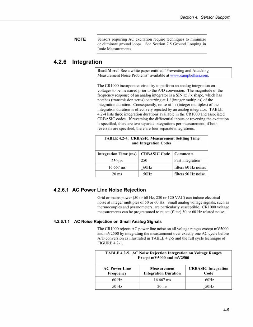
Section 4. Sensor Support
4-9
Sensors requiring AC excitation require techniques to minimize or eliminate ground loops. See Section 7.5 Ground Looping in Ionic Measurements.
4.2.6 Integration Read More! See a white paper entitled “Preventing and Attacking Measurement Noise Problems” available at www.campbellsci.com.
The CR1000 incorporates circuitry to perform an analog integration on voltages to be measured prior to the A/D conversion. The magnitude of the frequency response of an analog integrator is a SIN(x) / x shape, which has notches (transmission zeros) occurring at 1 / (integer multiples) of the integration duration. Consequently, noise at 1 / (integer multiples) of the integration duration is effectively rejected by an analog integrator. TABLE 4.2-4 lists three integration durations available in the CR1000 and associated CRBASIC codes. If reversing the differential inputs or reversing the excitation is specified, there are two separate integrations per measurement; if both reversals are specified, there are four separate integrations.
TABLE 4.2-4. CRBASIC Measurement Settling Time and Integration Codes
Integration Time (ms) CRBASIC Code Comments
250 μs 250 Fast integration
16.667 ms _60Hz filters 60 Hz noise. 20 ms _50Hz filters 50 Hz noise.
4.2.6.1 AC Power Line Noise Rejection Grid or mains power (50 or 60 Hz, 230 or 120 VAC) can induce electrical noise at integer multiples of 50 or 60 Hz. Small analog voltage signals, such as thermocouples and pyranometers, are particularly susceptible. CR1000 voltage measurements can be programmed to reject (filter) 50 or 60 Hz related noise.
4.2.6.1.1 AC Noise Rejection on Small Analog Signals The CR1000 rejects AC power line noise on all voltage ranges except mV5000 and mV2500 by integrating the measurement over exactly one AC cycle before A/D conversion as illustrated in TABLE 4.2-5 and the full cycle technique of FIGURE 4.2-1.
TABLE 4.2-5. AC Noise Rejection Integration on Voltage Ranges Except mV5000 and mV2500
AC Power Line Frequency
Measurement Integration Duration
CRBASIC Integration Code
60 Hz 16.667 ms _60Hz 50 Hz 20 ms _50Hz
NOTE

Section 4. Sensor Support
4-10
FIGURE 4.2-1. Full and ½ Cycle Integration Methods for AC Power Line Noise Rejection
4.2.6.1.2 AC Noise Rejection on Large Analog Signals
When rejecting AC noise on the 2500 mV and 5000 mV ranges, the CR1000 makes two fast measurements separated in time by ½ line cycle, as illustrated in FIGURE 4.2-1. For 60 Hz rejection , ½ line cycle = 8333 μs, meaning that the 2nd measurement must start 8333 μs after the integration for the first measurement was started. The A/D conversion time is approximately 170 μs, leaving a maximum input settling time of approximately 8333 μs - 170 μs = 8160 μs before the 2nd measurement is delayed too long to result in a rejection notch at 60 Hz. For 50 Hz rejection on the mV5000 and mV2500 input ranges, the maximum input settling time of approximately 10,000 - 170 μs = 9830 μs before the 2nd measurement is delayed too long to result in a rejection notch at 50 Hz. The CR1000 does not prevent or warn against setting the settling time beyond the ½ cycle limit. TABLE 4.2-6 lists details of the ½ line cycle AC power line noise rejection technique.

Section 4. Sensor Support
4-11
TABLE 4.2-6. AC Noise Rejection Integration on Voltage Ranges
mV5000 and mV2500
AC Power Line
Frequency
Measurement Integration
Time
CRBASIC Integration
Code
Default Settling
Time
Maximum Recommended Settling Time*
60 Hz 250 μs x 2 _60Hz 3000 μs 8330 μs 50 Hz 250 μs x 2 _50Hz 3000 μs 10000 μs *Excitation time equals settling time in measurements requiring excitation. The CR1000 cannot excite channels Vx/VX1 (VX1 (EX1)), Vx/VX2 (EX2), and Vx/VX3 (EX3) during A/D conversion. The ½ cycle technique with excitation limits the length of recommended excitation / settling time for the first measurement to ½ cycle. The CR1000 does not prevent or warn against setting a settling time beyond the ½ cycle limit. For example, a settling time of up to 50000 microseconds can be programmed, but the CR1000 will execute the measurement as follows:
1. CR1000 turns excitation on, waits 50000 microseconds, then makes the first measurement. 2. During A/D, CR1000 turns off excitation for ≈ 170 microseconds. 3. Excitation is switched on again for ½ cycle, then the second measurement is made.
Restated, a sensor does not see a continuous excitation of the length entered as the settling time before the second measurement if the settling time entered is greater than ½ cycle. Depending on the sensor used, a truncated second excitation may cause measurement errors.
4.2.7 Signal Settling Time When the CR1000 switches to an analog input channel or activates excitation for a bridge measurement, a settling time is required for the measured voltage to settle to its true value before being measured. The rate at which the signal settles is determined by the input settling time constant which is a function of both the source resistance and input capacitance.
Rise and decay waveforms are exponential. Figure 4.2-3 shows rising and decaying waveforms settling to the true signal level, Vso.
FIGURE 4.2-3. Input Voltage Rise and Transient Decay
The CR1000 delays after switching to a channel to allow the input to settle before initiating the measurement. The SettlingTime parameter of the associated measurement instruction is provided to allow the user to tailor measurement instructions settling times with 100 microsecond resolution. Default settling times are listed in TABLE 4.2-7, and are meant to provide sufficient signal settling in most cases. Additional settling time may be required when measuring high resistance (impedance) sensors and / or sensors
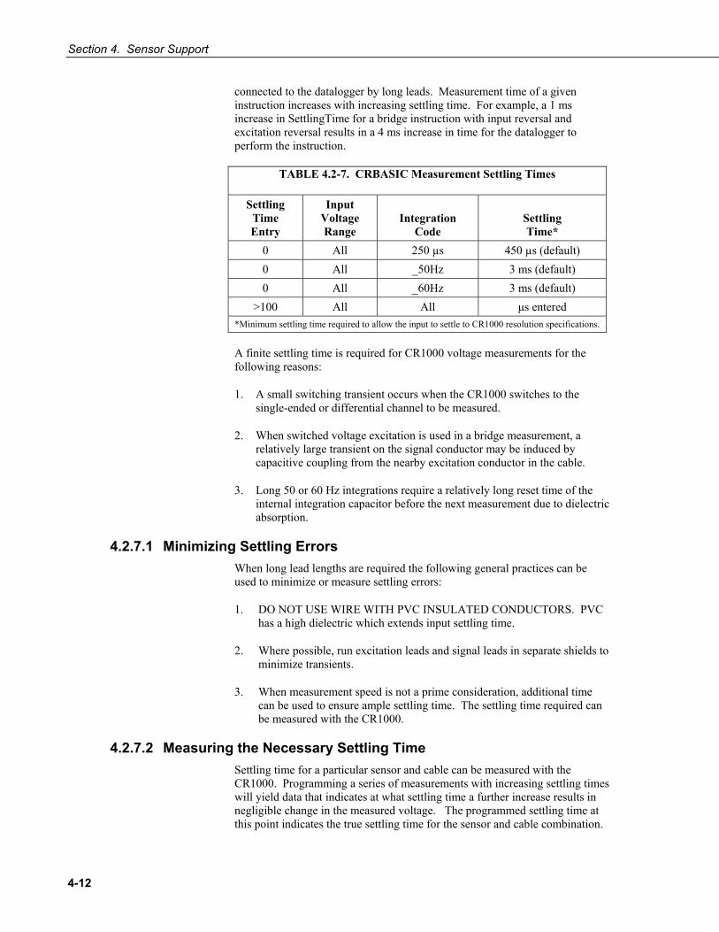
Section 4. Sensor Support
4-12
connected to the datalogger by long leads. Measurement time of a given instruction increases with increasing settling time. For example, a 1 ms increase in SettlingTime for a bridge instruction with input reversal and excitation reversal results in a 4 ms increase in time for the datalogger to perform the instruction.
TABLE 4.2-7. CRBASIC Measurement Settling Times
Settling Time Entry
Input Voltage Range
Integration
Code
Settling Time*
0 All 250 µs 450 µs (default) 0 All _50Hz 3 ms (default) 0 All _60Hz 3 ms (default)
>100 All All μs entered *Minimum settling time required to allow the input to settle to CR1000 resolution specifications.
A finite settling time is required for CR1000 voltage measurements for the following reasons:
1. A small switching transient occurs when the CR1000 switches to the single-ended or differential channel to be measured.
2. When switched voltage excitation is used in a bridge measurement, a relatively large transient on the signal conductor may be induced by capacitive coupling from the nearby excitation conductor in the cable.
3. Long 50 or 60 Hz integrations require a relatively long reset time of the internal integration capacitor before the next measurement due to dielectric absorption.
4.2.7.1 Minimizing Settling Errors When long lead lengths are required the following general practices can be used to minimize or measure settling errors:
1. DO NOT USE WIRE WITH PVC INSULATED CONDUCTORS. PVC has a high dielectric which extends input settling time.
2. Where possible, run excitation leads and signal leads in separate shields to minimize transients.
3. When measurement speed is not a prime consideration, additional time can be used to ensure ample settling time. The settling time required can be measured with the CR1000.
4.2.7.2 Measuring the Necessary Settling Time Settling time for a particular sensor and cable can be measured with the CR1000. Programming a series of measurements with increasing settling times will yield data that indicates at what settling time a further increase results in negligible change in the measured voltage. The programmed settling time at this point indicates the true settling time for the sensor and cable combination.

Section 4. Sensor Support
4-13
EXAMPLE 4.2-1 presents CRBASIC code to help determine settling time for a pressure transducer utilizing a high capacitance semi-conductor. The code consists of a series of full-bridge measurements (BrFull ()) with increasing settling times. The pressure transducer is placed in steady-state conditions so changes in measured voltage are attributable to settling time rather than changes in the measured pressure. Reviewing Section 9 CR1000 Programming may help in understanding the CRBASIC code in the example.
EXAMPLE 4.2-1. CRBASIC Code: Measuring Settling Time
'CR1000 Series Datalogger 'Program to measure the settling time of a sensor 'measured with a differential voltage measurement Public PT(20) 'Variable to hold the measurements DataTable (Settle,True,100) Sample (20,PT(),IEEE4) EndTable BeginProg Scan (1,Sec,3,0) BrFull (PT(1),1,mV7_5,1,Vx1,1,2500,True,True,100,250,1.0,0) BrFull (PT(2),1,mV7_5,1,Vx1,1,2500,True,True,200,250,1.0,0) BrFull (PT(3),1,mV7_5,1,Vx1,1,2500,True,True,300,250,1.0,0) BrFull (PT(4),1,mV7_5,1,Vx1,1,2500,True,True,400,250,1.0,0) BrFull (PT(5),1,mV7_5,1,Vx1,1,2500,True,True,500,250,1.0,0) BrFull (PT(6),1,mV7_5,1,Vx1,1,2500,True,True,600,250,1.0,0) BrFull (PT(7),1,mV7_5,1,Vx1,1,2500,True,True,700,250,1.0,0) BrFull (PT(8),1,mV7_5,1,Vx1,1,2500,True,True,800,250,1.0,0) BrFull (PT(9),1,mV7_5,1,Vx1,1,2500,True,True,900,250,1.0,0) BrFull (PT(10),1,mV7_5,1,Vx1,1,2500,True,True,1000,250,1.0,0) BrFull (PT(11),1,mV7_5,1,Vx1,1,2500,True,True,1100,250,1.0,0) BrFull (PT(12),1,mV7_5,1,Vx1,1,2500,True,True,1200,250,1.0,0) BrFull (PT(13),1,mV7_5,1,Vx1,1,2500,True,True,1300,250,1.0,0) BrFull (PT(14),1,mV7_5,1,Vx1,1,2500,True,True,1400,250,1.0,0) BrFull (PT(15),1,mV7_5,1,Vx1,1,2500,True,True,1500,250,1.0,0) BrFull (PT(16),1,mV7_5,1,Vx1,1,2500,True,True,1600,250,1.0,0) BrFull (PT(17),1,mV7_5,1,Vx1,1,2500,True,True,1700,250,1.0,0) BrFull (PT(18),1,mV7_5,1,Vx1,1,2500,True,True,1800,250,1.0,0) BrFull (PT(19),1,mV7_5,1,Vx1,1,2500,True,True,1900,250,1.0,0) BrFull (PT(20),1,mV7_5,1,Vx1,1,2500,True,True,2000,250,1.0,0) CallTable Settle NextScan EndProg
The first six measurements are shown in TABLE 4.2-8. Each trace in FIGURE 4.2-2. Settling Time for Pressure Transducer contains all 20 PT() values for a given record number, along with an averaged value showing the measurements as percent of final reading. The reading has settled to 99.5% of the final value by the fourteenth measurement, PT(14). This is a suitable accuracy for the application, so a settling time of 1400 μs is determined to be adequate.

Section 4. Sensor Support
4-14
Settling Time
0.036
0.037
0.038
0.039
0.04
0.041
0.042
0.043
0.044
1 2 3 4 5 6 7 8 9 10 11 12 13 14 15 16 17 18 19 20
Time (x100 us)
mV/
Volt
85
87
89
91
93
95
97
99
% o
f Fin
al V
alue
Series1Series2Series3Series4Series5Average %
FIGURE 4.2-2. Settling Time for Pressure Transducer
TABLE 4.2-8. First Six Values of Settling Time Data
TIMESTAMP RECORD PT(1) PT(2) PT(3) PT(4) PT(5) PT(6)
Smp Smp Smp Smp Smp Smp
1/3/2000 23:34 0 0.03638599 0.03901386 0.04022673 0.04042887 0.04103531 0.04123745
1/3/2000 23:34 1 0.03658813 0.03921601 0.04002459 0.04042887 0.04103531 0.0414396
1/3/2000 23:34 2 0.03638599 0.03941815 0.04002459 0.04063102 0.04042887 0.04123745
1/3/2000 23:34 3 0.03658813 0.03941815 0.03982244 0.04042887 0.04103531 0.04103531
1/3/2000 23:34 4 0.03679027 0.03921601 0.04022673 0.04063102 0.04063102 0.04083316
4.2.8 Self-Calibration Read More! Related topics can be found in Section 4.2.4
The CR1000 self-calibrates to compensate for changes induced by fluctuating operating temperatures and aging. Without self-calibration, measurement accuracy over the operational temperature range is worse by about a factor of 10. That is, over the extended temperature range of -40°C to 85°C, the accuracy specification of ±0.12% of reading can degrade to ±1% of reading with self-calibration disabled. If the temperature of the CR1000 remains the same, there is little calibration drift with self-calibration disabled.
Unless a Calibrate () instruction is present in the running CRBASIC program, the CR1000 automatically performs self-calibration during spare time in a slow sequence (background), with a segment of the calibration occurring every 4 seconds (s). If there is insufficient time to do the background calibration because of a consuming user program, the CR1000 will display the following warning at compile time: “Warning when Fast Scan x is running background calibration is disabled”.

Section 4. Sensor Support
4-15
The composite transfer function of the instrumentation amplifier, integrator, and analog-to-digital converter of the CR1000 is described by the following equation:
COUNTS = G * Vin + B
where COUNTS is the result from an analog-to-digital conversion, G is the voltage gain for a given input range, and B is the internally measured offset voltage.
Automatic self-calibration only calibrates the G and B values necessary to run a given CRBasic program, resulting in a program dependent number of self-calibration segments ranging from at least 6 to a maximum of 91. A typical number of segments required in self-calibration is 20 for analog ranges and 1 segment for the panel temperature measurement, totaling 21 segments. So, (21 segments) * (4 s / segment) = 84 s per complete self-calibration. The worst-case is (91 segments) * (4 s / segment) = 364 s per complete self-calibration.
During instrument power-up, the CR1000 computes calibration coefficients by averaging 10 complete sets of self-calibration measurements. After power up, newly determined G and B values are low-pass filtered as followed: Next_Value = (1/5) * New + (4/5) * Old. For a step change of the New value, the low-pass filter Next_Value = (1/5) * New + (4/5) * Old results in 20% settling for 1 New value, 49% settling for 3 New values, 67% settling for 5 New values, 89% settling for 10 New values, and 96% settling for 14 New values. If this rate of update for measurement channels is too slow, a user can utilize the Calibrate () instruction. The Calibrate () instruction computes the necessary G and B values every scan without any low-pass filtering.
For a VoltSe () instruction, B is determined as part of self-calibration only if the parameter MeasOff = 0. An exception is B for VoltSe () on the ±2500 mV input range with 250 μs integration, which is always determined in self-calibration for use internally. For a VoltDiff () instruction, B is determined as part of self-calibration only if the parameter RevDiff = 0.
VoltSe () and VoltDiff () instructions on a given input range with the same integration durations, utilize the same G, but different B values. The 6 input voltage ranges (±5000 mV, ±2500 mV, ±250 mV, ±25 mV, ±7.5 mV, and ±2.5 mV) along with the 3 different integration durations (250 μs, _50Hz, & _60Hz) result in a maximum of 18 different gains (G), and 18 offsets for VoltSe () measurements (B), and 18 offsets for VoltDiff () measurements (B) to be determined during CR1000 self-calibration (maximum of 54 values).
The various G and B values can be viewed in the Status Table as CalGain(1) through CalGain(18), CalSeOffset(1) through CalSeOffset(18), and CalDiffOffset(1) through CalDiffOffset(18), with an order of 250 μs integration, _60Hz integration, and _50Hz integration on the following input voltage ranges: ±5000 mV, ±2500 mV, ±250 mV, ±25 mV, ±7.5 mV, and ±2.5 mV.
An example of the Calibrate instruction for all input ranges is given as Calibrate (cal(1),true), where Dest is an array of 54 values, and Range ≠ 0 in order to calibrate all input ranges. TABLE 4.2-9 describes the 54 values generated from the Calibrate (cal(1),true) instruction.

Section 4. Sensor Support
4-16
TABLE 4.2-9. Values Generated by the Calibrate () Instruction
Array Element Description Typical Value
1 SE offset for ±5000 mV input range with 250 ms integration. ±5 LSB 2 Differential offset for ±5000 mV input range with 250 ms
integration. ±5 LSB
3 Gain for ±5000 mV input range with 250 ms integration. -1.34 mV/LSB 4 SE offset for ±2500 mV input range with 250 ms integration. ±5 LSB 5 Differential offset for ±2500 mV input range with 250 ms
integration. ±5 LSB
6 Gain for ±2500 mV input range with 250 ms integration. -0.67 mV/LSB 7 SE offset for ±250 mV input range with 250 ms integration. ±5 LSB 8 Differential offset for ±250 mV input range with 250 ms
integration. ±5 LSB
9 Gain for ±250 mV input range with 250 ms integration. -0.067 mV/LSB 10 SE offset for ±25 mV input range with 250 ms integration. ±5 LSB 11 Differential offset for ±25 mV input range with 250 ms
integration. ±5 LSB
12 Gain for ±25 mV input range with 250 ms integration. -0.0067 mV/LSB 13 SE offset for ±7.5 mV input range with 250 ms integration. ±10 LSB 14 Differential offset for ±7.5 mV input range with 250 ms
integration. ±10 LSB
15 Gain for ±7.5 mV input range with 250 ms integration. -0.002 mV/LSB 16 SE offset for ±2.5 mV input range with 250 ms integration. ±20 LSB 17 Differential offset for ±2.5 mV input range with 250 ms
integration. ±20 LSB
18 Gain for ±2.5 mV input range with 250 ms integration. -0.00067 mV/LSB 19 SE offset for ±5000 mV input range with 60 Hz integration. ±5 LSB 20 Differential offset for ±5000 mV input range with 60 Hz
integration. ±5 LSB
21 Gain for ±5000 mV input range with 60 Hz integration. -0.67 mV/LSB 22 SE offset for ±2500 mV input range with 60 Hz integration. ±5 LSB 23 Differential offset for ±2500 mV input range with 60 Hz
integration. ±5 LSB
24 Gain for ±2500 mV input range with 60 Hz integration. -0.34 mV/LSB 25 SE offset for ±250 mV input range with 60 Hz integration. ±5 LSB 26 Differential offset for ±250 mV input range with 60 Hz
integration. ±5 LSB
27 Gain for ±250 mV input range with 60 Hz integration. -0.067 mV/LSB 28 SE offset for ±25 mV input range with 60 Hz integration. ±5 LSB 29 Differential offset for ±25 mV input range with 60 Hz integration. ±5 LSB 30 Gain for ±25 mV input range with 60 Hz integration. -0.0067 mV/LSB

Section 4. Sensor Support
4-17
31 SE offset for ±7.5 mV input range with 60 Hz integration. ±10 LSB 32 Differential offset for ±7.5 mV input range with 60 Hz
integration. ±10 LSB
33 Gain for ±7.5 mV input range with 60 Hz integration. -0.002 mV/LSB 34 SE offset for ±2.5 mV input range with 60 Hz integration. ±20 LSB 35 Differential offset for ±2.5 mV input range with 60 Hz
integration. ±20 LSB
36 Gain for ±2.5 mV input range with 60 Hz integration. -0.00067 mV/LSB 37 SE offset for ±5000 mV input range with 50 Hz integration. ±5 LSB 38 Differential offset for ±5000 mV input range with 50 Hz
integration. ±5 LSB
39 Gain for ±5000 mV input range with 50 Hz integration. -0.67 mV/LSB 40 SE offset for ±2500 mV input range with 50 Hz integration. ±5 LSB 41 Differential offset for ±2500 mV input range with 50 Hz
integration. ±5 LSB
42 Gain for ±2500 mV input range with 50 Hz integration. -0.34 mV/LSB 43 SE offset for ±250 mV input range with 50 Hz integration. ±5 LSB 44 Differential offset for ±250 mV input range with 50 Hz
integration. ±5 LSB
45 Gain for ±250 mV input range with 50 Hz integration. -0.067 mV/LSB 46 SE offset for ±25 mV input range with 50 Hz integration. ±5 LSB 47 Differential offset for ±25 mV input range with 50 Hz integration. ±5 LSB 48 Gain for ±25 mV input range with 50 Hz integration. -0.0067 mV/LSB 49 SE offset for ±7.5 mV input range with 50 Hz integration. ±10 LSB 50 Differential offset for ±7.5 mV input range with 50 Hz
integration. ±10 LSB
51 Gain for ±7.5 mV input range with 50 Hz integration. -0.002 mV/LSB 52 SE offset for ±2.5 mV input range with 50 Hz integration. ±20 LSB 53 Differential offset for ±2.5 mV input range with 50 Hz
integration. ±20 LSB
54 Gain for ±2.5 mV input range with 50 Hz integration. -0.00067 mV/LSB
4.3 Bridge Resistance Measurements Many sensors detect phenomena by way of change in a resistive circuit. Thermistors, strain gages, and position potentiometers are examples. Resistance measurements are special case voltage measurements. By supplying a precise, known voltage to a resistive circuit, then measuring the returning voltage, resistance can be calculated.
Read More! Available resistive bridge completion modules are listed in Appendix F.11.

Section 4. Sensor Support
4-18
Five bridge measurement instructions are included in the CR1000. FIGURE 4.3-1 shows the circuits that are typically measured with these instructions. In the diagrams, resistors labeled Rs are normally the sensors and those labeled Rf are normally precision fixed (static) resistors. Circuits other than those diagrammed can be measured, provided the excitation and type of measurements are appropriate. Program Code EXAMPLE 4.3-1 shows CR1000 code for measuring and processing four wire full bridge circuits.
All bridge measurements have the option (RevEx) to make one set of measurements with the excitation as programmed and another set of measurements with the excitation polarity reversed. The offset error in the two measurements due to thermal EMFs can then be accounted for in the processing of the measurement instruction. The excitation channel maintains the excitation voltage or current until the hold for the analog to digital conversion is completed. When more than one measurement per sensor is necessary (four wire half bridge, three wire half bridge, six wire full bridge), excitation is applied separately for each measurement. For example, in the four-wire half-bridge, when the excitation is reversed, the differential measurement of the voltage drop across the sensor is made with the excitation at both polarities and then excitation is again applied and reversed for the measurement of the voltage drop across the fixed resistor.
Calculating the resistance of a sensor that is one of the legs of a resistive bridge requires additional processing following the bridge measurement instruction. FIGURE 4.3-1 lists the schematics of typical bridge configurations and the calculations necessary to compute the resistance of any single resistor, provided the values of the other resistors in the bridge circuit are known.
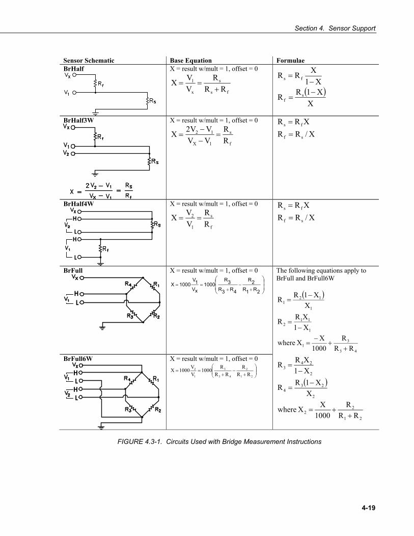
Section 4. Sensor Support
4-19
Sensor Schematic Base Equation Formulae BrHalf
X = result w/mult = 1, offset = 0
fs
s
x
1
RRR
VVX
+==
( )X
X1RR
X1XRR
sf
fs
−=
−=
BrHalf3W
X = result w/mult = 1, offset = 0
f
s
1X
12
RR
VVVV2X =
−−
= X/RRXRR
sf
fs
==
BrHalf4W
H
L H
L
X = result w/mult = 1, offset = 0
f
s
1
2
RR
VVX == X/RR
XRR
sf
fs
==
BrFull
H L
X = result w/mult = 1, offset = 0
⎟⎟⎠
⎞⎜⎜⎝
⎛
+−
+==
2R1R2R
4R3R3R
1000xV1V
1000X The following equations apply to BrFull and BrFull6W
( )
1
112
1
121
X1XRR
XX1RR
−=
−=
43
31 RR
R1000
XX where+
+−
=
BrFull6W
H L
H L
X = result w/mult = 1, offset = 0
⎟⎟⎠
⎞⎜⎜⎝
⎛+
−+
==21
2
43
3
1
2
RRR
RRR1000
VV1000X
( )2
234
2
243
XX1RR
X1XRR
−=
−=
21
22 RR
R1000
XX where+
+=
FIGURE 4.3-1. Circuits Used with Bridge Measurement Instructions

Section 4. Sensor Support
4-20
EXAMPLE 4.3-1. CRBASIC Code: 4 Wire Full Bridge Measurement and Processing
'Declare Variables Public X Public X1 Public R1 Public R2 Public R3 Public R4 'Main Program BeginProg R2 = 1000 'Resistance of R2 R3 = 1000 'Resistance of R3 R4 = 1000 'Resistance of R4 Scan(500,mSec,1,0) 'Full Bridge measurement: BrFull (X,1,mV2500,1,1,1,2500,True,True,0,_60Hz,1.0,0.0) X1 = ((-1 * X) / 1000) + (R3 / (R3 + R4)) R1 = (R2 * (1 - X1)) / X1 NextScan EndProg
4.3.1 Strain Calculations Read More! FieldCalStrain in Section 11.1.6 FieldCalStrain () Demonstration Program.
A principal use of the four wire full bridge is the measurement of strain gages in structural stress analysis. StrainCalc () calculates microstrain, με, from an appropriate formula for the particular strain bridge configuration used. All strain gages supported by StrainCalc () use the full bridge electronic configuration. In strain gage parlance, “quarter bridge”, “half bridge” and “full bridge” refer to the number of active elements in the full bridge, i.e., 1, 2, or 4 active elements respectively.
StrainCalc () requires a bridge configuration code. TABLE 4.3-1 shows the equation invoked by each configuration code. Each code can be preceded by a negative sign (-). Use a positive code when the bridge is configured so the output decreases with increasing strain. Use a negative code when the bridge is configured so the output increases with increasing strain. In the equations below, a negative code sets the polarity of Vr to negative (-).
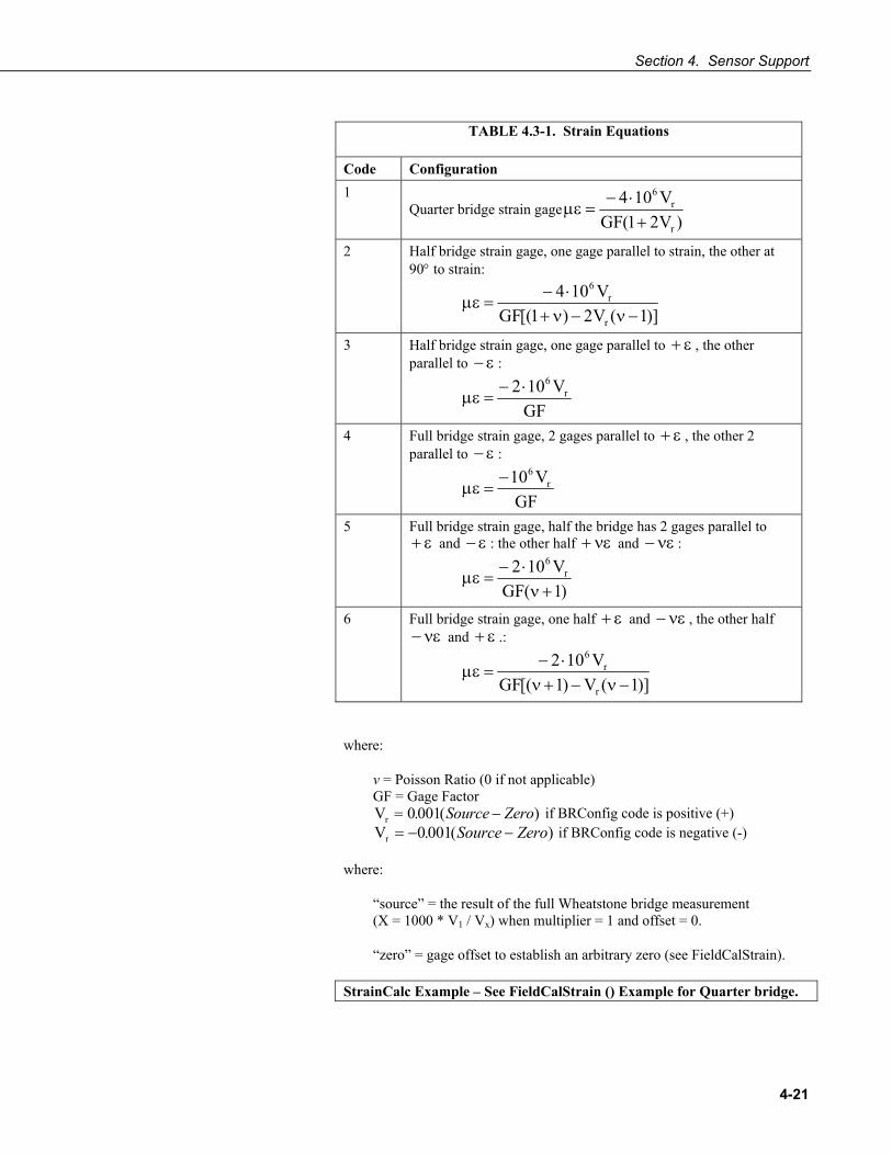
Section 4. Sensor Support
4-21
TABLE 4.3-1. Strain Equations
Code Configuration 1
Quarter bridge strain gage)V21(GF
V104
r
r6
+⋅−
=με
2 Half bridge strain gage, one gage parallel to strain, the other at 90° to strain:
)]1(V2)1[(GF
V104
r
r6
−ν−ν+⋅−
=με
3 Half bridge strain gage, one gage parallel to ε+ , the other parallel to ε− :
GF
V102 r6⋅−
=με
4 Full bridge strain gage, 2 gages parallel to ε+ , the other 2 parallel to ε− :
GF
V10 r6−
=με
5 Full bridge strain gage, half the bridge has 2 gages parallel to ε+ and ε− : the other half νε+ and νε− :
)1(GF
V102 r6
+ν⋅−
=με
6 Full bridge strain gage, one half ε+ and νε− , the other half νε− and ε+ .:
)]1(V)1[(GF
V102
r
r6
−ν−+ν⋅−
=με
where:
v = Poisson Ratio (0 if not applicable) GF = Gage Factor Vr = −0 001. ( )Source Zero if BRConfig code is positive (+) Vr = − −0 001. ( )Source Zero if BRConfig code is negative (-)
where:
“source” = the result of the full Wheatstone bridge measurement (X = 1000 * V1 / Vx) when multiplier = 1 and offset = 0.
“zero” = gage offset to establish an arbitrary zero (see FieldCalStrain).
StrainCalc Example – See FieldCalStrain () Example for Quarter bridge.

Section 4. Sensor Support
4-22
4.4 Thermocouple Measurements Thermocouples are easy to use with the CR1000. They are also inexpensive. However, they pose several challenges to the acquisition of accurate temperature data, particularly when using external reference junctions. Campbell Scientific strongly encourages any user of thermocouples to carefully evaluate Section 4.4.1 Error Analysis of Thermocouple Measurements. An introduction to thermocouple measurements is located in Section 2.2.
The micro-volt resolution and low-noise voltage measurement capability of the CR1000 is well suited for measuring thermocouples. A thermocouple consists of two dissimilar metal wires joined together at one end to form a junction. Practical thermocouples are constructed from two parallel insulated wires of dissimilar metals soldered or welded together at the junction. A temperature difference between the junction and the unconnected wires opposite the junction induces a temperature dependent voltage between the wires, referred to as the Seebeck effect. Measurement of the voltage between the unconnected wires opposite the junction provides a direct measure of the temperature difference between the junction and the measurement end. Metallic connections (e.g., solder) between the two dissimilar metal wires and the measurement device form parasitic thermocouple junctions, the effects of which cancel if the two wires are at the same temperature. Consequently, the two wires at the measurement end of the thermocouple, referred to as the reference junction, are placed in close proximity and thermally connected so that they are at the same temperature. Knowledge of the reference junction temperature provides the determination of a reference junction compensation voltage, corresponding to the temperature difference between the reference junction and 0°C. This compensation voltage, combined with the measured thermocouple voltage, can be used to compute the absolute temperature of the thermocouple junction. To facilitate thermocouple measurements, a thermistor is integrated into the CR1000 wiring panel for measurement of the reference junction temperature by means of the PanelTemp () instruction.
TCDiff () and TCSe () thermocouple instructions determine thermocouple temperatures using the following sequence. First, the temperature (°C) of the reference junction is determined. A reference junction compensation voltage is next computed based on the temperature difference between the reference junction and 0 °C. If the reference junction is the CR1000 analog input terminals, the temperature is conveniently measured with the PanelTemp () instruction. The actual thermocouple voltage is measured and combined with the reference junction compensation voltage. It is then used to determine the thermocouple junction temperature based on a polynomial approximation of NIST thermocouple calibrations.
4.4.1 Error Analysis The error in the measurement of a thermocouple temperature is the sum of the errors in the reference junction temperature measurement plus the temperature-to-voltage polynomial fit error, the non-ideality of the thermocouple (deviation from standards published in NIST Monograph 175), the thermocouple voltage measurement accuracy, and the voltage-to-temperature polynomial fit error (difference between NIST standard and CR1000 polynomial approximations).
NOTE

Section 4. Sensor Support
4-23
The discussion of errors that follows is limited to these errors in calibration and measurement and does not include errors in installation or matching the sensor and thermocouple type to the environment being measured.
4.4.1.1 Panel Temperature The panel temperature thermistor (Betatherm 10K3A1A) is just under the panel in the center of the two rows of analog input terminals. It has an interchangeability specification of 0.1°C for temperatures between 0 and 70°C. Below freezing and at higher temperatures, this specification is degraded. Combined with possible errors in the completion resistor measurement and the Steinhart and Hart equation used to calculate the temperature from resistance, the accuracy of panel temperature is estimated at ± 0.1°C over -0 to 40°C, ± 0.3°C from -25 to 50°C, and ± 0.8°C from -55 to 85°C.
The error in the reference temperature measurement is a combination of the error in the thermistor temperature and the difference in temperature between the panel thermistor and the terminals the thermocouple is connected to. The terminal strip cover should always be used when making thermocouple measurements. It insulates the terminals from drafts and rapid fluctuations in temperature as well as conducting heat to reduce temperature gradients. In a typical installation where the CR1000 is in a weather proof enclosure not subject to violent swings in temperature or uneven solar radiation loading, the temperature difference between the terminals and the thermistor is likely to be less than 0.2°C.
Panel Temperature error summary
-0.1
0
0.1
0.2
0.3
0.4
0.5
0.6
0.7
0.8
-55 -35 -15 5 25 45 65 85
Sum of Worst Case Errors
Thermistor Tolerance
CR1000 Measurement
Completion Resistor Error
S&H Err
FIGURE 4.4-1. Panel Temperature Errors
Panel Temperature ºC
Erro
rºC
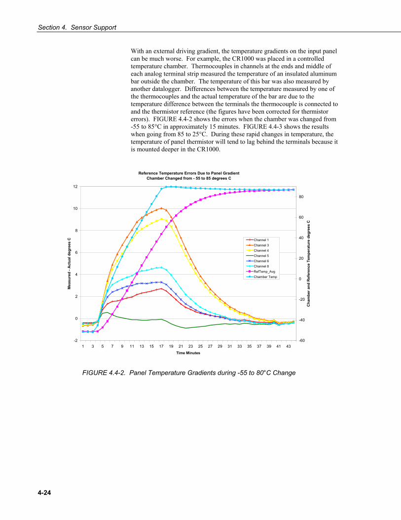
Section 4. Sensor Support
4-24
With an external driving gradient, the temperature gradients on the input panel can be much worse. For example, the CR1000 was placed in a controlled temperature chamber. Thermocouples in channels at the ends and middle of each analog terminal strip measured the temperature of an insulated aluminum bar outside the chamber. The temperature of this bar was also measured by another datalogger. Differences between the temperature measured by one of the thermocouples and the actual temperature of the bar are due to the temperature difference between the terminals the thermocouple is connected to and the thermistor reference (the figures have been corrected for thermistor errors). FIGURE 4.4-2 shows the errors when the chamber was changed from -55 to 85°C in approximately 15 minutes. FIGURE 4.4-3 shows the results when going from 85 to 25°C. During these rapid changes in temperature, the temperature of panel thermistor will tend to lag behind the terminals because it is mounted deeper in the CR1000.
Reference Temperature Errors Due to Panel GradientChamber Changed from - 55 to 85 degrees C
-2
0
2
4
6
8
10
12
1 3 5 7 9 11 13 15 17 19 21 23 25 27 29 31 33 35 37 39 41 43Time Minutes
Mea
sure
d - A
ctua
l deg
rees
C
-60
-40
-20
0
20
40
60
80
Cha
mbe
r and
Ref
eren
ce T
empe
ratu
re d
egre
es C
Channel 1Channel 3Channel 4Channel 5Channel 6Channel 8RefTemp_AvgChamber Temp
FIGURE 4.4-2. Panel Temperature Gradients during -55 to 80°C Change

Section 4. Sensor Support
4-25
Reference Temperature Errors Due to Panel Gradient Chamber Changed from 85 to 25 degrees C
-6
-5
-4
-3
-2
-1
0
1
2
1 3 5 7 9 11 13 15 17 19 21 23 25 27 29 31 33 35 37 39 41 43 45 47 49 51 53 55
Time Minutes
Mea
sure
d - A
ctua
l deg
rees
C
20
30
40
50
60
70
80
90
Cha
mbe
r and
Ref
eren
ce T
empe
ratu
res
deg.
C
Channel 1Channel 3Channel 4Channel 6Channel 8RefTemp_AvgChamber Temp
FIGURE 4.4-3. Panel Temperature Gradients during 80 to 25°C Change
4.4.1.2 Thermocouple Limits of Error The standard reference that lists thermocouple output voltage as a function of temperature (reference junction at 0°C) is the NIST (National Institute of Standards and Technology) Monograph 175 (1993). ANSI (American National Standards Institute) has established limits of error on thermocouple wire which is accepted as an industry standard (ANSI MC 96.1, 1975). TABLE 4.4-1 gives the ANSI limits of error for standard and special grade thermocouple wire of the types accommodated by the CR1000.
TABLE 4.4-1. Limits of Error for Thermocouple Wire (Reference Junction at 0°C)
Limits of Error Thermocouple Temperature (Whichever is greater) Type Range°C Standard Special T -200 to 0 ± 1.0°C or 1.5% 0 to 350 ± 1.0°C or 0.75% ± 0.5°C or 0.4% J 0 to 750 ± 2.2°C or 0.75% ± 1.1°C or 0.4% E -200 to 0 ± 1.7°C or 1.0% 0 to 900 ± 1.7°C or 0.5% ± 1.0°C or 0.4% K -200 to 0 ± 2.2°C or 2.0% 0 to 1250 ± 2.2°C or 0.75% ± 1.1°C or 0.4% R or S 0 to 1450 ± 1.5°C or 0.25% ± 0.6°C or 0.1% B 800 to 1700 ± 0.5% Not Estab.

Section 4. Sensor Support
4-26
When both junctions of a thermocouple are at the same temperature there is no voltage produced (law of intermediate metals). A consequence of this is that a thermocouple cannot have an offset error; any deviation from a standard (assuming the wires are each homogeneous and no secondary junctions exist) is due to a deviation in slope. In light of this, the fixed temperature limits of error (e.g., ±1.0°C for type T as opposed to the slope error of 0.75% of the temperature) in the table above are probably greater than one would experience when considering temperatures in the environmental range (i.e., the reference junction, at 0°C, is relatively close to the temperature being measured, so the absolute error — the product of the temperature difference and the slope error — should be closer to the percentage error than the fixed error). Likewise, because thermocouple calibration error is a slope error, accuracy can be increased when the reference junction temperature is close to the measurement temperature. For the same reason differential temperature measurements, over a small temperature gradient, can be extremely accurate.
To quantitatively evaluate thermocouple error when the reference junction is not fixed at 0°C limits of error for the Seebeck coefficient (slope of thermocouple voltage vs. temperature curve) are needed for the various thermocouples. Lacking this information, a reasonable approach is to apply the percentage errors, with perhaps 0.25% added on, to the difference in temperature being measured by the thermocouple.
4.4.1.3 Accuracy of Thermocouple Voltage Measurement The -25 to 50°C accuracy of a CR1000 differential voltage measurement, without input reversal, is specified as ± (0.12% of the measured voltage plus an offset error of 3 times the basic resolution of the range being used to make the measurement plus 2 μV). The offset error reduces to 1.5 times the basic resolution plus 1 μV if the differential measurement is made utilizing the option to reverse the differential input (RevDiff = True).
For optimum resolution, the ±2.5 mV range is used for all but high temperature measurements (TABLE 4.4-2). Using the 0.67 μV basic resolution of the ±2.5 mV range in the offset equations above, the offset portion of the accuracy specification is 4 μV without input reversal or 2 μV with input reversal. This offset portion of the accuracy specification dominates the voltage measurement error for temperatures in the environmental range. At the full scale the other part of the accuracy term is 0.12% of 2.5 mV = 2 μV. For example, assume that a type T thermocouple is used to measure a temperature of 45°C and that the reference temperature is 25°C. The voltage output by the thermocouple is 830.7 µV. At 45 degrees a type T thermocouple outputs 42.4 µV per °C. The percent of reading error in the voltage measurement is 0.0012 * 830.7 µV = 1 µV or 0.023°C (1 / 42.4). The basic resolution on the ±2.5 mV range is 0.67 µV or 0.016°C. The 2 μV offset is an error of 0.047°C. Thus, the possible error due to the voltage measurement is 0.07°C when reversing differential inputs, or 0.118°C when not reversing differential inputs.
Error in the temperature due to inaccuracy in the measurement of the thermocouple voltage is worst at temperature extremes, particularly when the temperature and thermocouple type require using the 250 mV range. For example, assume type K (chromel-alumel) thermocouples are used to measure temperatures around 1300°C. The TC output is on the order of 52 mV, requiring the ±250 mV input range. At 1300°C, a K thermocouple outputs 34.9 µV per °C. The percent of reading error in the voltage measurement is 0.0012

Section 4. Sensor Support
4-27
* 52 mV = 62 µV or 1.78°C (62 / 34.9). The basic resolution on the 250 mV range is 66.7 µV or 1.91°C. Thus, the possible error due to the voltage measurement is 4.38°C when reversing differential inputs, or 7.28°C when not reversing differential inputs.
TABLE 4.4-2. Voltage Range for Maximum Thermocouple Resolution (with reference temperature at 20°C)
TC Type and temp. range °C
Temp. range for ±2.5 mV range
Temp. range for ±7.5 mV range
Temp. range for ±25 mV range
Temp. range for ±250 mV range
T -270 to 400 -45 to 75 -270 to 180 -270 to 400 not used E -270 to 1000 -20 to 60 -120 to 130 -270 to 365 >365 K -270 to 1372 -40 to 80 -270 to 200 -270 to 620 >620 J -210 to 1200 -25 to 65 -145 to 155 -210 to 475 >475 B 0 to 1820 0 to 710 0 to 1265 0 to 1820 not used R -50 to 1768 -50 to 320 -50 to 770 -50 to 1768 not used S -50 to 1768 -50 to 330 -50 to 820 -50 to 1768 not used N -270 to 1300 -80 to 105 -270 to 260 -270 to 725 >725
When the thermocouple measurement junction is in electrical contact with the object being measured (or has the possibility of making contact) a differential measurement should be made to avoid ground looping.
4.4.1.4 Noise on Voltage Measurement The typical input noise on the ±2.5 mV range for a differential measurement with 16.67 ms integration and input reversal is 0.19 μV RMS. On a type T thermocouple (approximately 40 μV/°C), this is 0.005°C. Note that this is an RMS value; some individual readings will vary by greater than this.
4.4.1.5 Thermocouple Polynomial: Voltage to Temperature NIST Monograph 175 gives high order polynomials for computing the output voltage of a given thermocouple type over a broad range of temperatures. In order to speed processing and accommodate the CR1000's math and storage capabilities, four separate 6th order polynomials are used to convert from volts to temperature over the range covered by each thermocouple type. TABLE 4.4-3 gives error limits for the thermocouple polynomials.

Section 4. Sensor Support
4-28
TABLE 4.4-3. Limits of Error on CR1000 Thermocouple Polynomials
(Relative to NIST Standards)
TC Type Range °C Limits of Error °C T -270 to 400 -270 to -200 + 18 @ -270 -200 to -100 ± 0.08 -100 to 100 ± 0.001 100 to 400 ± 0.015 J -150 to 760 ± 0.008 -100 to 300 ± 0.002 E -240 to 1000 -240 to -130 ± 0.4 -130 to 200 ± 0.005 200 to 1000 ± 0.02 K -50 to 1372 -50 to 950 ± 0.01 950 to 1372 ± 0.04
4.4.1.6 Reference Junction Compensation: Temperature to Voltage Thermocouple instructions TCDiff () and TCSe () include the parameter TRef to incorporate the reference junction temperature into the measurement. A reference junction compensation voltage is computed from TRef as part of the thermocouple instruction, based on the temperature difference between the reference junction and 0°C. The polynomials used to determine the reference junction compensation voltage do not cover the entire thermocouple range, as illustrated in TABLE 4.4-3 and TABLE 4.4-4. Substantial errors in the reference junction compensation voltage will result if the reference junction temperature is outside of the polynomial fit ranges given in TABLE 4.4-4.
The reference junction temperature measurement can come from a PanelTemp () instruction, or from any other temperature measurement of the reference junction. The standard and extended (-XT) operating ranges for the CR1000 are -25 to +50 °C and –55 to 85 °C, respectively. These ranges also apply to the reference junction temperature measurement using PanelTemp ().
Two sources of error arise when the reference temperature is out of the polynomial fit range. The most significant error is in the calculated compensation voltage; however a small error is also created by non-linearities in the Seebeck coefficient.
TABLE 4.4-4. Reference Temperature Compensation Range and Polynomial Error Relative to NIST Standards
TC Type Range °C Limits of Error °C T -100 to 100 ± 0.001 J -150 to 296 ± 0.005 E -150 to 206 ± 0.005 K -50 to 100 ± 0.01

Section 4. Sensor Support
4-29
4.4.1.7 Error Summary The magnitude of the errors described in Section 4.4.1 illustrate that the greatest sources of error in a thermocouple temperature measurement are likely due to the limits of error on the thermocouple wire and in the reference temperature. Errors in the thermocouple and reference temperature linearizations are extremely small, and error in the voltage measurement is negligible.
TABLE 4.4-5 illustrates the relative magnitude of these errors in the environmental range. It shows a worst case situation where all errors are maximum and additive. A temperature of 45°C is measured with a type T (copper-constantan) thermocouple, using the ±2.5 mV range. The reference thermistor measures 25.1 °C, The terminal the thermocouple is connected to is 0.05°C cooler than the reference thermistor (0.15°C error).
TABLE 4.4-5. Example of Errors in Thermocouple Temperature
Source Error: °C : % of Total Error Single Differential
250 µs Integration Reversing Differential
50/60 Hz Rejection Integration ANSI TC Error
(1°C) TC Error 1% Slope
ANSI TC Error (1°C)
TC Error 1% Slope
Reference Temp. 0.15°:11.5% 0.15°:29.9% 0.15°:12.2% 0.15°:34.7% TC Output 1.0°:76.8% 0.2°:39.8% 1.0°:81.1% 0.2°:46.3% Voltage Measurement
0.12°:9.2% 0.12°:23.9% 0.07°:5.7% 0.07°:16.2%
Noise 0.03°:2.3% 0.03°:6.2% 0.01°:0.8% 0.01°:2.3% Reference Linearization
0.001°:0.1% 0.001°:0.2% 0.001°:0.1% 0.001°:0.25%
Output Linearization
0.001°:0.1% 0.001°:0.2% 0.001°:0.1% 0.001°:0.25%
Total Error 1.302°:100% 0.502°:100% 1.232°:100% 0.432°:100%
4.4.1.8 Use of External Reference Junction An external junction in an insulated box is often used to facilitate thermocouple connections. It can reduce the expense of thermocouple wire when measurements are made long distances from the CR1000. Making the external junction the reference junction, which is preferable in most applications, is accomplished by running copper wire from the junction to the CR1000. Alternatively, the junction box can be used to couple extension grade thermocouple wire to the thermocouples, with the PanelTemp () instruction used to determine the reference junction temperature.
Extension grade thermocouple wire has a smaller temperature range than standard thermocouple wire, but meets the same limits of error within that range. One situation in which thermocouple extension wire is advantageous is when the junction box temperature is outside the range of reference junction compensation provided by the CR1000. This is only a factor when using type K thermocouples, since the upper limit of the reference compensation

Section 4. Sensor Support
4-30
polynomial fit range is 100°C and the upper limit of the extension grade wire is 200°C. With the other types of thermocouples the reference compensation polynomial fit range equals or is greater than the extension wire range. In any case, errors can arise if temperature gradients exist within the junction box.
FIGURE 4.4-4 illustrates a typical junction box wherein the reference junction is the CR1000. Terminal strips are a different metal than the thermocouple wire. Thus, if a temperature gradient exists between A and A' or B and B', the junction box will act as another thermocouple in series, creating an error in the voltage measured by the CR1000. This thermoelectric offset voltage is also a factor when the junction box is used as the reference junction. This offset can be minimized by making the thermal conduction between the two points large and the distance small. The best solution in the case where extension grade wire is being connected to thermocouple wire is to use connectors which clamp the two wires in contact with each other.
CR9000
H
L
A' A
B' B
Junction Box
TCCR1000 Junction Box
FIGURE 4.4-4. Diagram of Junction Box
When an external junction box is also the reference junction, the points A, A', B, and B' in FIGURE 4.4-4 all need to be very close in temperature (isothermal) to measure a valid reference temperature, and to avoid thermoelectric offset voltages. The box should contain elements of high thermal conductivity, which will act to rapidly equilibrate any thermal gradients to which the box is subjected. It is not necessary to design a constant temperature box; it is desirable that the box respond slowly to external temperature fluctuations. Radiation shielding must be provided when a junction box is installed in the field. Care must also be taken that a thermal gradient is not induced by conduction through the incoming wires. The CR1000 can be used to measure the temperature gradients within the junction box.
4.5 Pulse Count Measurement FIGURE 4.5-1 is a generalized schematic showing connection of a pulse sensor to the CR1000. The CR1000 features two dedicated pulse input channels, P1 and P2. It also features eight digital I/O channels, C1 through C8, for measuring various pulse output sensors. Activated by the PulseCount () instruction, dedicated 24-bit counters on P1, P2 and C1 through C8 are used to accumulate all counts over the user specified scan interval. Counters are read at the beginning of each scan and cleared. Counters overflow if accumulated counts exceed 16,777,216 pulses during a scan; the result is an erroneous measurement. PulseCount () instruction parameters specify the pulse input type, channel used, and pulse output option.

Section 4. Sensor Support
4-31
Sensor
Pulse Channel
Ground
FIGURE 4.5-1. Schematic of a Pulse Sensor on a CR1000
The PulseCount () instruction cannot be used in a Slow Sequence scan.
Execution of PulseCount () within a scan involves determining the accumulated counts in each dedicated 24-bit counter since execution of the last PulseCount (). PulseCount () parameter (POption) determines if the output is in counts (POption = 0) or frequency (POption = 1). Counts are the preferred output option for measuring number of tips from a tipping bucket rain gage, or the number of times a door opens. Many pulse sensors, such as anemometers and flow meters, are calibrated in terms of frequency (Hz or counts / second), and are usually measured with the frequency option.
Resolution of the pulse counters is one count. Resolution of frequency is (1 / measurement interval). For example, the frequency resolution of PulseCount () returning a result every 1 second is 1 Hz. Accuracy is limited by a small scan interval error of ±(3 ppm of scan interval + 10 μs) plus the measurement resolution error of ± 1 Hz. The sum is essentially ± 1 Hz. Extending a 1 second measurement interval to 10 seconds, either by increasing the scan interval or by averaging, improves the resulting frequency resolution from 1 Hz to 0.1 Hz. Averaging can be accomplished by the Average (), AvgRun (), and AvgSpa () instructions. Alternatively, entering a number greater than 1 in the POption parameter enters an averaging interval in milliseconds for a direct running average computation, e.g, an entry of 1000 produces a 1 second running average.
4.5.1 Pulse Input Channels P1 and P2 Read More! Review pulse counter specifications in Section 3.3. Review pulse counter programming in CRBASIC Help for the PulseCount () instruction.
FIGURE 4.5-2 illustrates pulse input types measured by the CR1000. Dedicated pulse input channels P1 and P2 can be configured to read high- frequency pulses, low-level AC signals, or switch closure.
Input channel expansion devices for all input types are available from Campbell Scientific. Refer to Appendix F for more information.
NOTE
NOTE

Section 4. Sensor Support
4-32
FIGURE 4.5-2. Pulse Input Types
Maximum input voltage on pulse channels P1 and P2 is ±20 V. If pulse inputs of higher than ±20 V need to be measured, third party external signal conditioners should be employed. Contact a Campbell Scientific applications engineer if assistance is needed. Under no circumstances should voltages greater than ±50 V be measured.
4.5.1.1 High-frequency Pulse (P1 – P2) Internal hardware routes high-frequency pulse to an inverting CMOS input buffer with input hysteresis. The CMOS input buffer is guaranteed to be an output zero level with its input ≥ 2.2 V, and guaranteed to be an output one with its input ≤ 0.9 V. An RC input filter with approximately a 1 μs time constant precedes the inverting CMOS input buffer, resulting in an amplitude reduction of high frequency signals between the P1 and P2 terminal blocks and the inverting CMOS input buffer as illustrated in FIGURE 4.5-3. For a 0 to 5 Volt square wave applied to P1 and P2, the maximum frequency that can be counted in high-frequency mode is approximately 250 kHz.
0 2 .10 6 4 .10 6 6 .10 6 8 .10 6 1 .10 5
0
1
2
3
4
55.1
0.1−
Before
After
1 10 5−×0 time
FIGURE 4.5-3. Amplitude reduction of pulse-count waveform before and after 1 μs time constant filter.
CAUTION

Section 4. Sensor Support
4-33
When a pulse channel is configured for high-frequency pulse, an internal 100 kΩ pull-up resistor to +5 Volt on the P1 or P2 input is automatically employed. This pull-up resistor accommodates open-collector (open-drain) output devices for high-frequency input.
4.5.1.2 Low-Level AC (P1 – P2) Rotating magnetic pickup sensors commonly generate AC output voltages ranging from millivolts at low rotational speeds to several volts at high rotational speeds. Channels P1 and P2 contain internal signal conditioning hardware for measuring low-level AC output sensors. When configured for low-level AC, P1 and P2 measure signals ranging from 20 mV RMS (±28 mV peak) to 14 V RMS (±20 V peak). Internal AC coupling is incorporated in the low-level AC hardware to eliminate DC offset voltages of up to ±0.5 V.
4.5.1.3 Switch Closure (P1 – P2) Switch-closure mode of channels P1 and P2 measures switch closure events, such as occur with a common tipping bucket rain gage. An internal 100 kΩ pull-up resistor pulls the P1 or P2 input to +5 Volt with the switch open, whereas a switch closure to ground pulls the P1 or P2 input voltage to 0 V. An internal 3.3 ms time constant RC debounce filter is used to eliminate multiple counts from a single switch closure event.
4.5.2 Pulse Input on Digital I/O Channels C1 – C8 Read More! Review digital I/O channel specifications in Section 3.3. Review pulse counter programming in CRBASIC Help for the PulseCount () instruction.
Digital I/O channels C1 – C8 can be configured to measure high-frequency and switch closure signals. Switch closure signals require external pull-up resistors. Normal input voltage levels are between -8.0 V and +16 Vdc. If pulse inputs < -8.0 V or > +16 V need to be measured, external signal conditioning must employed. Contact Campbell Scientific for further information.
Caution: Under no circumstances should voltages greater than ±50 V be connected to channels C1 – C8.
Low-level AC signals cannot be measured directly on channels C1 – C8. Refer to Appendix F.9 for information on peripheral modules available to convert low-level AC signals to high-frequency square-wave signals.
4.5.2.1 High-frequency (C1 – C8) Ports C1 – C8 have a small 25 ns input RC filter time constant between the terminal block and the CMOS input buffer, which allows for higher frequency operation (400 kHz maximum) compared with channels P1 and P2 (250 kHz maximum).
When configured for input, ports C1 – C8 each go into a digital CMOS input buffer that recognizes inputs ≥ 3.8 V as high and inputs ≤ 1.2 V as low.

Section 4. Sensor Support
4-34
4.5.2.2 Switch Closure (C1 – C8) To configure C1 – C8 for switch closure, an external pull-up resistor, as shown in Figure 4.5-4, is required to counteract an internal 100 kΩ pull-down resistor. Inputs must be pulled to > 3.8 V with the switch open for reliable switch closure measurements.
Figure 4.5-4 Schematic illustrating use of pull-up resistors when measuring switch closure on channels C1 – C8.
A pull-up resistor of 1 – 20 kΩ is recommended when connecting to a +5 V supply, and a pull-up resistor of 2.5 – 150 kΩ is recommended when connecting to a +12 V supply to provide adequate logic levels. Software switch debouncing of switch closure is incorporated in the switch-closure mode for channels C1 – C8.
Note Maximum switch closure frequency measured is 150 kHz.
4.5.2.3 Edge Timing (C1 – C8) Time between pulse edges can be measured. Results can be expressed in terms of microseconds or hertz. To read more concerning edge timing, refer to CRBASIC Help for the TimerIO () instruction.
4.6 Period Averaging Measurements The CR1000 can measure the period of a signal on any single-ended analog input channel (SE 1 -16). The specified number of cycles are timed with a resolution of 92 ns, making the resolution of the period measurement 92 ns divided by the number of cycles chosen.
Low-level signals are amplified prior to a voltage comparator. The internal voltage comparator is referenced to the user-entered threshold. The threshold parameter allows a user to reference the internal voltage comparator to voltages other than 0 V. For example, a threshold of 2500 mV allows a 0 to 5 V digital signal to be sensed by the internal comparator without the need of any additional input conditioning circuitry. The threshold allows direct connection of standard digital signals, but is not recommended for small amplitude sensor signals. For sensor amplitudes less than 20 mV peak-to-peak, a DC blocking capacitor is recommended to center the signal at CR1000 ground (threshold = 0) because of offset voltage drift along with limited accuracy (± 10 mV) and

Section 4. Sensor Support
4-35
resolution (1.2 mV) of a threshold other than 0. FIGURE 4.6-1 shows an example circuit.
c
Vo s
SensorwithDCoffset
Silicon diodessuch as 1N4001
To single - endedinput
1µF
D1
D2R
10k
FIGURE 4.6-1. Input conditioning circuit for low-level and high level period averaging.
The minimum pulse width requirements increase (maximum frequency decreases) with increasing gain. Signals larger than the specified maximum for a range will saturate the gain stages and prevent operation up to the maximum specified frequency. As shown in FIGURE 4.6-1, back-to-back diodes are recommended to limit large amplitude signals to within the input signal ranges.
Noisy signals with slow transitions through the voltage threshold have the potential for extra counts around the comparator switch point. A voltage comparator with 20 mV of hysteresis follows the voltage gain stages. The effective input referred hysteresis equals 20 mV divided by the selected voltage gain. The effective input referred hysteresis on the ± 25 mV range is 2 mV; consequently, 2 mV of noise on the input signal could cause extraneous counts. For best results, select the largest input range (smallest gain) that meets the minimum input signal requirements.
4.7 SDI-12 Recording Read More! Section 11.3 SDI-12 Sensor Support and Section 10.11 Serial Input/Output.
SDI-12 is a communications protocol developed to transmit digital data from smart sensors to data acquisition units. It is a simple protocol, requiring only a single communication wire. Typically, the data acquisition unit also supplies power (12V and ground) to the SDI-12 sensor. The CR1000 is equipped with four SDI-12 input channels (C1, C3, C5, C7) and an SDI12Recorder () CRBASIC instruction.
4.8 RS-232 and TTL Recording Read More! Section 10.11 Serial Input / Output and Section 11.8 Serial I/O.
The CR1000 can normally receive and record RS-232 and 0-5V logic data from sensors designed to transmit via these protocols. Data are received through the CS I/O port with the proper interface (Appendix F.10.2), the RS-232 port, or the digital I/O communication ports (C1 & C2, C3 & C4, C5 &
CAUTION

Section 4. Sensor Support
4-36
C6, C7 & C8). If additional serial inputs are required, serial input expansion modules (Appendix F.10.1) can be connected to increase the number of serial ports. Serial data are usually captured as strings, which are then parsed (split up) as defined in the user entered program.
Digital I/O communication ports (control ports) only transmit 0-5V logic. However, they read most true RS232 input signals. When connecting serial sensors to an RX control port, the sensor power consumption may increase by a few milliamps due to voltage clamps. An external resistor may need to be added in series to the RX line to limit the current drain, although this is not advisable at very high baud rates.
4.9 Field Calibration of Linear Sensor Read More! Section 11.1 FieldCal has complete FieldCal information.
Calibration increases accuracy of a measurement device by adjusting its output, or the measurement of its output, to match independently verified quantities. Adjusting a sensor output directly is preferred, but not always possible or practical. By adding FieldCal () or FieldCalStrain () instructions to the CR1000 program, a user can easily adjust the measured output of a linear sensors by modifying multipliers and offsets.
4.10 Cabling Effects on Measurements Sensor cabling can have significant effects on sensor response and accuracy. This is usually only a concern with sensors acquired from manufacturers other than Campbell Scientific. Campbell Scientific sensors are engineered for optimal performance with factory installed cables.
4.10.1 Analog Sensors Cable length in analog sensors is most likely to affect the signal settling time. For more information, see Section 4.2.7.
4.10.2 Pulse Sensors Because of the long interval between switch closures in tipping bucket rain gages, appreciable capacitance can build up between wires in long cables. A built up charge can cause arcing when the switch closes, shortening switch life. As shown in Figure 4.10-1, a current limiting100 ohm resistor, connected in series at the switch, prevents arcing. This resistor is installed on all rain gages currently sold by Campbell Scientific.
FIGURE 4.10-1. Current Limiting Resistor in a Tipping Bucket Rain Gage Circuit
NOTE
Section 4. Sensor Support
4-37
4.10.3 Serial Sensors 4.10.3.1 RS-232 Sensors
RS-232 sensors cable lengths should be limited to 50 feet.
4.10.3.2 SDI-12 Sensors The SDI-12 standard allows cable lengths of up to 200 feet. Campbell Scientific does not recommend SDI-12 sensor lead lengths greater than 200 feet; however, longer lead lengths can sometimes be accommodated by increasing the wire gage and/or powering the sensor with a second 12 vdc power supply placed near the sensor.

Section 4. Sensor Support
4-38

5-1
Section 5. Measurement and Control Peripherals
Peripheral devices are available for expanding the CR1000’s on-board input / output capabilities. Classes of peripherals are discussed below according to use. Some peripherals are designed as SDM (Synchronous Devices for Measurement) devices. SDM devices are intelligent peripherals that receive instruction from and send data to the CR1000 over a proprietary 3-wire serial communications link utilizing channels C1, C2, and C3.
Read More! For complete information on available measurement and control peripherals, go to Appendix F Sensors and Peripherals, www.campbellsci.com, or contact a Campbell Scientific applications engineer.
5.1 Analog Input Expansion Mechanical relay and solid state relay multiplexers are available to expand the number of analog sensor inputs. Multiplexers are designed for single-ended, differential, bridge resistance, or thermocouple inputs.
5.2 Pulse Input Expansion Modules Pulse input expansion modules are available for switch closure, state, pulse count and frequency measurements, and interval timing.
5.3 Serial Input Expansion Modules Capturing input from intelligent serial output devices can be challenging. Several Campbell Scientific serial I/O modules are designed to facilitate reading and parsing serial data. Campbell Scientific recommends consulting with an applications engineer when deciding which serial input module is suited to a particular application.
5.4 Control Output Controlling power to an external device is a common function of the CR1000. Devices are available for binary (on / off) or analog (variable) control.
Many devices can conveniently be controlled with the SW-12 (Switched 12 Volt) terminal on the CR1000. Applications requiring more control channels or greater power sourcing capacity can usually be satisfied by using one of Campbell Scientific’s multiple-channel control modules or by using control ports (C1 - C8) in conjunction with single-channel switching relays.

Section 5. Measurement and Control Peripherals
5-2
5.4.1 Binary Control 5.4.1.1 Digital I/O Ports
Each of eight digital I/O ports (C1 - C8) can be configured as an output port and set low (0 V) or high (5 V) using the PortSet () or WriteIO () instructions. A digital output port is normally used to operate an external relay driver circuit because the port itself has very limited drive capability (2.0 mA minimum at 3.5 V).
5.4.1.2 Switched 12 V Control The SW-12 port can be set low (0 V) or high (12 V) using the PortSet () or SW12 () instructions. The port is often used to control low power devices such as sensors that require 12 V during measurement. Current sourcing must be limited to 900 mA or less at 20°C.
A 12V switching circuit, driven by a digital I/O port, is also available from Campbell Scientific.
The SW-12 supply is unregulated and can supply up to 900 mA at 20°C and up to 630 mA at 50°C. A resettable polymeric fuse protects against over-current. Reset is accomplished by removing the load or turning off the SW-12 for several seconds.
5.4.1.3 Relays and Relay Drivers Several relay drivers are manufactured by Campbell Scientific. Contact a Campbell Scientific applications engineer for more information, or get more information at www.campbellsci.com.
Compatible, inexpensive and reliable single-channel relay drivers for a wide range of loads are available from various electronic vendors such as Crydom, Newark, Mouser, etc.
5.4.1.4 Component Built Relays FIGURE 5.4-1 shows a typical relay driver circuit in conjunction with a coil driven relay which may be used to switch external power to some device. In this example, when the control port is set high, 12 V from the datalogger passes through the relay coil, closing the relay which completes the power circuit and turns on the fan.
In other applications it may be desirable to simply switch power to a device without going through a relay. FIGURE 5.4-2 illustrates a circuit for switching external power to a device without using a relay. If the peripheral to be powered draws in excess of 75 mA at room temperature (limit of the 2N2907A medium power transistor), the use of a relay (FIGURE 5.4-1) is required.
NOTE

Section 5. Measurement and Control Peripherals
5-3
FIGURE 5.4-1. Relay Driver Circuit with Relay
FIGURE 5.4-2. Power Switching without Relay
5.5 Analog Control / Output Devices The CR1000 can scale measured or processed values and transfer these values in digital form to an analog output device. The analog output device performs a digital-to-analog conversion to output an analog voltage or current. The output level is maintained until updated by the CR1000. Refer to Appendix F.8 for information concerning available continuous analog output modules.
5.6 Other Peripherals 5.6.1 TIMs
Terminal Input Modules (TIMs) are devices that provide simple measurement support circuits in a convenient package. TIMs include voltage dividers for cutting the output voltage of sensors to voltage levels compatible with the CR1000, modules for completion of resistive bridges, and shunt modules for measurement of analog current sensors. Refer to Appendix F.11 for information concerning available TIM modules.

Section 5. Measurement and Control Peripherals
5-4
5.6.2 Vibrating Wire Vibrating wire modules interface vibrating wire transducers to the CR1000. Refer to Appendix F.9 for information concerning available vibration wire interface modules.
5.6.3 Low-level AC Low-level AC input modules increase the number of low-level AC signals a CR1000 can monitor by converting low-level AC to high-frequency pulse. Refer to Appendix F.9 for information concerning available pulse input modules.

6-1
Section 6. CR1000 Power Supply Reliable power is the foundation of a reliable data acquisition system. When designing a power supply, consideration should be made regarding worst-case power requirements and environmental extremes.
Excessive switching noise or AC ripple present on a DC power supply can increase measurement noise. Noise sources include power transformers, regulators, and grid or mains power inclusively. Using high quality power regulators reduces noise due to power regulation. Utilizing 50 Hz or 60 Hz integration times for voltage measurements (see Section 4) improves rejection of power supply induced noise. The CRBasic standard deviation instruction, SDEV () can be used to evaluate measurement noise.
Contact Campbell Scientific if assistance in selecting a power supply is needed, particularly with applications in extreme environments.
6.1 Power Requirement The CR1000 operates from a DC power supply with voltage ranging from 9.6 to 16 V. It is internally protected against accidental polarity reversal. A transient voltage suppressor (TVS) diode on the 12 V power input terminal provides transient protection by clamping voltages in the range of 19 to 21 V. Sustained input voltages in excess of 19 V can damage the TVS diode.
The 12V and SW12 terminals on the wiring panel are not regulated by the CR1000; they obtain power directly from the POWER IN terminal. When using the CR1000 wiring panel to source power to other 12 V devices, be sure the power supply regulates the voltage within the range acceptable to the connected device.
6.2 Calculating Power Consumption Read More! Section 3.3 Specifications System Power Requirements.
System operating time for batteries can be determined by dividing the battery capacity (ampere-hours) by the average system current drain (amperes). The CR1000 typically draws 0.5 mA in the sleep state (with display off), 0.6 mA with a 1 Hz sample rate, and >10 mA with a 100 Hz sample rate.
6.3 Power Supplies Appendix F.3 lists power supplies available from Campbell Scientific, including alkaline and solar options. Complete power supply information is available in manual or brochure form at www.campbellsci.com.
CAUTION

Section 6. CR1000 Power Supply
6-2
6.4 Battery Connection When connecting external power to the CR1000, remove the green POWER IN connector from the CR1000 front panel. Insert the positive 12 V lead into the terminal marked “12V”. Insert the ground lead in the terminal marked “G” (ground). The CR1000 is internally protected against, but will not function with, reversed external power polarity.
6.5 Vehicle Power Connections If a CR1000 is powered by a motor vehicle supply, a second supply may be needed. When starting the motor of the vehicle, the battery voltage may drop below 9.6 V. This causes the CR1000 to stop measurements until the voltage again equals or exceeds 9.6 V. A second supply can be provided to prevent measurement lapses during vehicle starting. FIGURE 6.5-1 illustrate how a second power supply should be connected to the CR1000. The diode OR connection causes the supply with the largest voltage to power the CR1000 and prevents the second backup supply from attempting to power the vehicle.
CR1000Panel
+12V
G
FIGURE 6.5-1. Connecting CR1000 to Vehicle Power Supply

7-1
Section 7. Grounding Grounding the CR1000 and its peripheral devices and sensors is critical in all applications. Proper grounding will ensure the maximum ESD (electrostatic discharge) protection and higher measurement accuracy.
7.1 ESD Protection ESD (electrostatic discharge) can originate from several sources, the most common, and most destructive, being primary and secondary lightning strikes. Primary lightning strikes hit the datalogger or sensors directly. Secondary strikes induce a voltage in power lines or sensor wires.
The primary devices for protection against ESD are gas-discharge tubes (GDT). All critical inputs and outputs on the CR1000 are protected with GDTs or transient voltage suppression diodes. GDTs fire at 150 V to allow current to be diverted to the earth ground lug. To be effective, the earth ground lug must be properly connected to earth (chassis) ground. As shown in FIGURE 7.1-1, the power ground and signal ground are independent lines until joined inside the CR1000.

Section 7. Grounding
7-2
FIGURE 7.1-1. Schematic of CR1000 Grounds
The 9-pin serial I/O ports on the CR1000 are another path for transients. Communications paths such a telephone or short-haul modem lines should have spark gap protection. Spark gap protection is often an option with these products, so it should always be requested when ordering. Spark gaps for these devices must be connected to either the CR1000 earth ground lug, the enclosure ground, or to the earth (chassis) ground.
A good earth (chassis) ground will minimize damage to the datalogger and sensors by providing a low resistance path around the system to a point of low potential. Campbell Scientific recommends that all dataloggers be earth (chassis) grounded. All components of the system (dataloggers, sensors, external power supplies, mounts, housings, etc.) should be referenced to one common earth (chassis) ground.
In the field, at a minimum, a proper earth ground will consist of a 6 to 8 foot copper sheathed grounding rod driven into the earth and connected to the CR1000 Ground Lug with a 12 AWG wire. In low conductive substrates, such as sand, very dry soil, ice, or rock, a single ground rod will probably not
Tie analog signal shields and returns to grounds ( ) located in analog input terminal strips.
Tie 5 V, SW-12, 12 V and C1-C8 returns into power grounds (G).
Star Ground at Ground Lug
External Power Input
Tie pulse-counter returns into grounds ( ) in pulse-counter terminal strip. Large excitation return currents may also be tied into this ground in order to minimize induced single-ended offset voltages in half bridge measurements.

Section 7. Grounding
7-3
provide an adequate earth ground. For these situations, consult the literature on lightning protection or contact a qualified lightning protection consultant.
In vehicle applications, the earth ground lug should be firmly attached to the vehicle chassis with 12 AWG wire or larger.
In laboratory applications, locating a stable earth ground is challenging, but still necessary. In older buildings, new AC receptacles on older AC wiring may indicate that a safety ground exists when in fact the socket is not grounded. If a safety ground does exist, it is good practice to verify that it carries no current. If the integrity of the AC power ground is in doubt, also ground the system through the buildings, plumbing or another connection to earth ground.
7.1.1 Lightning Protection The most common and destructive ESDs are primary and secondary lightning strikes. Primary lightning strikes hit instrumentation directly. Secondary strikes induce voltage in power lines or wires connected to instrumentation. While elaborate, expensive and nearly infallible lightning protection systems are available, Campbell Scientific has for many years employed a simple and inexpensive design that protects most systems in most circumstances. It is, however, not infallible.
Lightning strikes may damage or destroy the CR1000 and associated sensors and power supplies.
In addition to protections discussed in Section 7.1, use of a simple lightning rod and low-resistance path to earth ground is adequate protection in many installations. A lightning rod serves two purposes. Primarily, it serves as a preferred strike point. Secondarily, it dissipates charge, reducing the chance of a lightning strike. FIGURE 7.1-2 shows a simple lightning protection scheme utilizing a lightning rod, metal mast, heavy gage ground wire, and ground rod to direct damaging current away from the CR1000.
NOTE

Section 7. Grounding
7-4
FIGURE 7.1-2. Lightning Protection Scheme
7.2 Common Mode Range To make a differential measurement, voltage inputs must be within the CR1000 common mode range of ±5 V. The common mode range is the voltage range, relative to CR1000 ground, within which both inputs of a differential measurement must lie, in order for the differential measurement to be made. For example, if the high side of a differential input is at 4 V and the low side is at 3 V relative to CR1000 ground, there is no problem. A measurement made on the ±5000 mV range will return 1000 mV. However, if the high input is at 5.8 V and the low input is at 4.8 V, the measurement can not be made because the high input is outside of the ±5 V common mode range. The CR1000 indicates the overrange by returning NAN (not-a-number). Sensors that have a floating output, or are not referenced to ground through a separate connection, may need the CR1000 to use a voltage range “C” option to pull the sensor into common mode range or to have the one side of the differential input (usually the low input) connected to ground to ensure the signal remains within the common mode range.

Section 7. Grounding
7-5
Common mode range can be exceeded when the CR1000 is measuring the output from a sensor which has its own grounded power supply and the low side of the signal is referenced to the sensor’s power supply ground. If the CR1000 ground and the sensor ground are at sufficiently different potentials, the signal will exceed the common mode range. To solve this problem, the sensor power ground and the CR1000 ground should be connected, creating one ground for the system.
Problems with exceeding common mode range can be encountered when the CR1000 is used to read the output of external signal conditioning circuitry if a good ground connection does not exist between the external circuitry and the CR1000. When operating where AC power is available, it is not always safe to assume that a good ground connection exists through the AC wiring. If a CR1000 is used to measure the output from a laboratory instrument (both plugged into AC power and referencing ground to outlet ground), the best practice is to run a ground wire between the CR1000 and the external circuitry.
7.3 Single-Ended Measurement Reference Low-level single-ended voltage measurements are sensitive to ground potential fluctuations. The grounding scheme in the CR1000 has been designed to eliminate ground potential fluctuations due to changing return currents from 12V, SW-12, 5V, and the control ports. This is accomplished by utilizing separate signal grounds ( ) and power grounds (G). To take advantage of this design, observe the following grounding rule:
Always connect a device’s ground next to the active terminal associated with that ground. Several ground wires can be connected to the same ground terminal.
Examples:
1. Connect 5 Volt, 12 Volt, and control grounds to G terminals.
2. Connect excitation grounds to the closest terminal on the excitation terminal block.
3. Connect the low side of single-ended sensors to the nearest terminal on the analog input terminal blocks.
4. Connect shield wires to the nearest terminal on the analog input terminal blocks.
If offset problems occur because of shield or ground leads with large current flow, tying the problem leads into the terminals next to the excitation and pulse-counter channels should help. Problem leads can also be tied directly to the ground lug to minimize induced single-ended offset voltages.
7.4 Ground Potential Differences Because a single-ended measurement is referenced to CR1000 ground, any difference in ground potential between the sensor and the CR1000 will result in a measurement error. Differential measurements MUST be used when the
NOTE
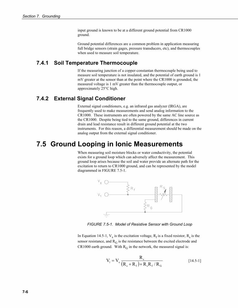
Section 7. Grounding
7-6
input ground is known to be at a different ground potential from CR1000 ground.
Ground potential differences are a common problem in application measuring full bridge sensors (strain gages, pressure transducers, etc), and thermocouples when used to measure soil temperature.
7.4.1 Soil Temperature Thermocouple If the measuring junction of a copper-constantan thermocouple being used to measure soil temperature is not insulated, and the potential of earth ground is 1 mV greater at the sensor than at the point where the CR1000 is grounded, the measured voltage is 1 mV greater than the thermocouple output, or approximately 25°C high.
7.4.2 External Signal Conditioner External signal conditioners, e.g. an infrared gas analyzer (IRGA), are frequently used to make measurements and send analog information to the CR1000. These instruments are often powered by the same AC line source as the CR1000. Despite being tied to the same ground, differences in current drain and lead resistance result in different ground potential at the two instruments. For this reason, a differential measurement should be made on the analog output from the external signal conditioner.
7.5 Ground Looping in Ionic Measurements When measuring soil moisture blocks or water conductivity, the potential exists for a ground loop which can adversely affect the measurement. This ground loop arises because the soil and water provide an alternate path for the excitation to return to CR1000 ground, and can be represented by the model diagrammed in FIGURE 7.5-1.
FIGURE 7.5-1. Model of Resistive Sensor with Ground Loop
In Equation 14.5-1, Vx is the excitation voltage, Rf is a fixed resistor, Rs is the sensor resistance, and RG is the resistance between the excited electrode and CR1000 earth ground. With RG in the network, the measured signal is:
( ) Gfsfs
sx1 R/RRRR
RVV++
= [14.5-1]

Section 7. Grounding
7-7
RsRf/RG is the source of error due to the ground loop. When RG is large, the equation reduces to the ideal. The geometry of the electrodes has a great effect on the magnitude of this error. The Delmhorst gypsum block used in the 227 probe has two concentric cylindrical electrodes. The center electrode is used for excitation; because it is encircled by the ground electrode, the path for a ground loop through the soil is greatly reduced. Moisture blocks which consist of two parallel plate electrodes are particularly susceptible to ground loop problems. Similar considerations apply to the geometry of the electrodes in water conductivity sensors.
The ground electrode of the conductivity or soil moisture probe and the CR1000 earth ground form a galvanic cell, with the water/soil solution acting as the electrolyte. If current was allowed to flow, the resulting oxidation or reduction would soon damage the electrode, just as if DC excitation was used to make the measurement. Campbell Scientific probes are built with series capacitors in the leads to block this DC current. In addition to preventing sensor deterioration, the capacitors block any DC component from affecting the measurement.

Section 7. Grounding
7-8

8-1
Section 8. CR1000 Configuration The CR1000 may require changes to factory default settings depending on the application. Most settings concern telecommunications between the CR1000 and a network or PC.
Good News! The CR1000 is shipped factory ready with all settings and firmware necessary to communicate with a PC via RS-232 and to accept and execute user application programs.
8.1 DevConfig DevConfig (Device Configuration Utility) is the preferred tool for configuring the CR1000. It is made available as part of LoggerNet, PC400, and at www.campbellsci.com. Most settings can also be entered through the CR1000KD (Section 17.6 Settings).
Features of DevConfig include:
• Communicates with devices via direct RS-232 only.
• Sends operating systems to supported device types.
• Sets datalogger clocks and sends program files to dataloggers.
• Identifies operating system types and versions.
• Provides a reporting facility wherein a summary of the current configuration of a device can be shown, printed or saved to a file. The file can be used to restore settings, or set settings in like devices.
• Provides a terminal emulator useful in configuring devices not directly supported by DevConfig’s graphical user interface.
• Shows Help as prompts and explanations. Help for the appropriate settings for a particular device can also be found in the user’s manual for that device.
• Updates from Campbell Scientific's web site.
As shown in FIGURE 8.1-1, the DevConfig window is divided into two main sections: the device selection panel on the left side and tabs on the right side. After choosing a device on the left, choose from the list of the serial ports (COM1, COM2, etc.) installed on the PC. A selection of baud rates is offered only if the device supports more than one baud rate. The page for each device presents instructions to set up the device to communicate with DevConfig. Different device types offer one or more tabs on the right.

Section 8. CR1000 Configuration
8-2
FIGURE 8.1-1. DevConfig CR1000 Facility
When the Connect button is pressed, the device type, serial port, and baud rate selector controls become disabled and, if DevConfig is able to connect to the CR1000, the button will change from "Connect" to "Disconnect".
8.2 Sending the Operating System 8.2.1 Sending OS with DevConfig
The CR1000 is shipped with the operating system pre-loaded. However, OS updates are made available at www.campbellsci.com and can be sent to the CR1000. FIGURE 8.2-1 and FIGURE 8.2-2 show DevConfig windows displayed during the OS download process.
Sending an operating system with DevConfig will erase all existing data and reset all settings to factory defaults.
CAUTION

Section 8. CR1000 Configuration
8-3
FIGURE 8.2-1. DevConfig OS download window for CR1000.
The text at right gives the instructions for sending the OS. Follow these instructions.
When the Start button is clicked, DevConfig offers a file open dialog box that prompts for the operating system file (*.obj file). When the CR1000 is then powered-up, DevConfig starts to send the operating system.
When the operating system has been sent, a message dialog will appear similar to the one shown in FIGURE 8.2-2.
FIGURE 8.2-2. Dialog Box Confirming a Successful OS Download

Section 8. CR1000 Configuration
8-4
The information in the dialog helps to corroborate the signature of the operating system sent.
8.2.2 Sending OS to Remote CR1000 Operating systems can be sent remotely using the Program Send feature in LoggerNet / PC400 / RTDAQ / PC200W. Beginning with OS version 16, sending an OS via Program Send retains settings unless changes in the new OS prevent it.
To ensure a remote OS download does not alter telecommunications settings, observe the precautions indicated in Sections 8.2.1 and 8.2.2.
EXAMPLE 8.2-1 lists text in a common default .cr1 file.
EXAMPLE 8.2-1. CRBASIC Code: A simple Default.CR1 file to control SW-12 switched power terminal. BeginProg Scan (1,Sec,0,0) If TimeIntoInterval (15,60,Sec) Then SW12 (1) If TimeIntoInterval (45,60,Sec) Then SW12 (0) NextScan EndProg
Depending on the method and quality of telecommunications, sending an OS via Program Send may take a very long time amount of time, so be conscious of connection charges.
8.2.3 Sending OS Using CF Card Refer to Section 12.5 File Control.
8.3 Settings 8.3.1 Settings via DevConfig
The CR1000 has a number of properties, referred to as “settings”, some of which are specific to the PakBus communications protocol.
Read More! PakBus is discussed in Section 14 PakBus Overview and the PakBus Networking Guide available at www.campbellsci.com.
DevConfig | Settings Editor tab provides access to most PakBus settings, however, the Deployment tab makes configuring most of these settings easier.
CAUTION
CAUTION

Section 8. CR1000 Configuration
8-5
FIGURE 8.3-1. DevConfig Settings Editor
As shown in FIGURE 8.3-1, the top of the Settings Editor is a grid that allows the user to view and edit the settings for the device. The grid is divided into two columns with the setting name appearing in the left hand column and the setting value appearing in the right hand column. Change the currently selected cell with the mouse or by using up-arrow and down-arrow keys as well as the Page-Up and Page-Down keys. When clicking in the setting names column, the value cell associated with that name will automatically be made active. Edit a setting by selecting the value, pressing the F2 key or by double clicking on a value cell with the mouse. The grid will not allow read-only settings to be edited.
The bottom of the Settings Editor displays help for the setting that has focus on the top of the screen.
Once a setting is changed, click Apply or Cancel. These buttons will only become enabled after a setting has been changed. If the device accepts the settings, a configuration summary dialogue is shown (FIGURE 8.3-2) that gives the user a chance to save and print the settings for the device.

Section 8. CR1000 Configuration
8-6
FIGURE 8.3-2. Summary of CR1000 Configuration
Clicking the Factory Defaults button on the Settings Editor will send a command to the device to revert to its factory default settings. The reverted values will not take effect until the final changes have been applied. This button will remain disabled if the device does not support the DevConfig protocol messages.
Clicking Save on the summary screen will save the configuration to an XML file. This file can be used to load a saved configuration back into a device by clicking Read File and Apply.

Section 8. CR1000 Configuration
8-7
8.3.1.1 Deployment Tab
FIGURE 8.3-3. DevConfig Deployment Tab
As shown in FIGURE 8.3-3, the Deployment tab allows the user to configure the datalogger prior to deploying it. Deployment tab settings can also be accessed through the Setting Editor tab and the Status table.
8.3.1.1.1 Datalogger Sub-Tab
Serial Number displays the CR1000 serial number. This setting is set at the factory and cannot be edited.
OS Version displays the operating system version that is in the CR1000. The default station name is the CR1000 serial number.
Station Name displays the name that is set for this station.
PakBus Address allows users to set the PakBus address of the datalogger. The allowable range is between 1 and 4094. Each PakBus device should have a unique PakBus address. Addresses >3999 force other PakBus devices to respond regardless of their respective PakBus settings. See the PakBus Networking Guide for more information.
Security – See Section 3.1.7
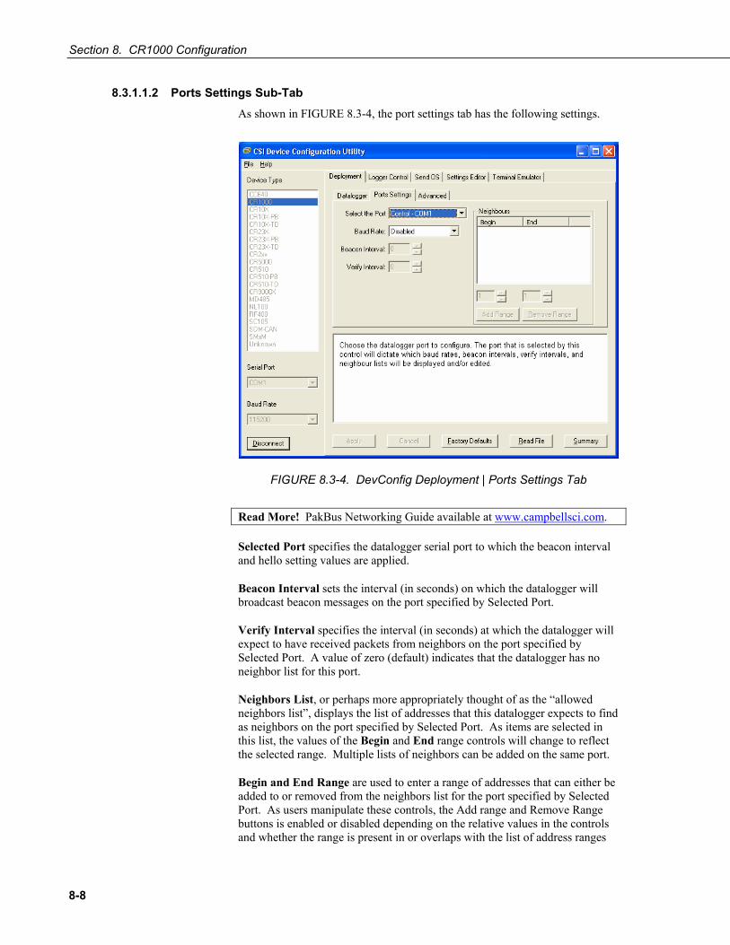
Section 8. CR1000 Configuration
8-8
8.3.1.1.2 Ports Settings Sub-Tab
As shown in FIGURE 8.3-4, the port settings tab has the following settings.
FIGURE 8.3-4. DevConfig Deployment | Ports Settings Tab
Read More! PakBus Networking Guide available at www.campbellsci.com.
Selected Port specifies the datalogger serial port to which the beacon interval and hello setting values are applied.
Beacon Interval sets the interval (in seconds) on which the datalogger will broadcast beacon messages on the port specified by Selected Port.
Verify Interval specifies the interval (in seconds) at which the datalogger will expect to have received packets from neighbors on the port specified by Selected Port. A value of zero (default) indicates that the datalogger has no neighbor list for this port.
Neighbors List, or perhaps more appropriately thought of as the “allowed neighbors list”, displays the list of addresses that this datalogger expects to find as neighbors on the port specified by Selected Port. As items are selected in this list, the values of the Begin and End range controls will change to reflect the selected range. Multiple lists of neighbors can be added on the same port.
Begin and End Range are used to enter a range of addresses that can either be added to or removed from the neighbors list for the port specified by Selected Port. As users manipulate these controls, the Add range and Remove Range buttons is enabled or disabled depending on the relative values in the controls and whether the range is present in or overlaps with the list of address ranges

Section 8. CR1000 Configuration
8-9
already set up. These controls are disabled if the Verify Interval value is set to zero.
Add Range will cause the range specified in the Begin and End range to be added to the list of neighbors to the datalogger on the port specified by Selected Port. This control is disabled if the value of the Verify Interval is zero or if the end range value is less than the begin range value.
Remove Range will remove the range specified by the values of the Begin and End controls from the list of neighbors to the datalogger on the port specified by Selected Port. This control is disabled if the range specified is not present in the list or if the value of Verify Interval is set to zero.
Help is displayed at the bottom of the Deployment tab. When finished, Apply the settings to the datalogger. The Summary window will appear. Save or Print the settings to archive or to use as a template for another datalogger.
Cancel causes the datalogger to ignore the changes. Read File provides the opportunity to load settings saved previously from this or another similar datalogger. Changes loaded from a file will not be written to the datalogger until Apply is clicked.
8.3.1.1.3 Advanced Sub-Tab
FIGURE 8.3-5. DevConfig Deployment | Advanced Tab
Is Router allows the datalogger to act as a PakBus router.
PakBus Nodes Allocation indicates the maximum number of PakBus devices the CR1000 will communicate with if it is set up as a router. This setting is used to allocate memory in the CR1000 to be used for its routing table.
Max Packet Size is the size of PakBus packets transmitted by the CR1000.
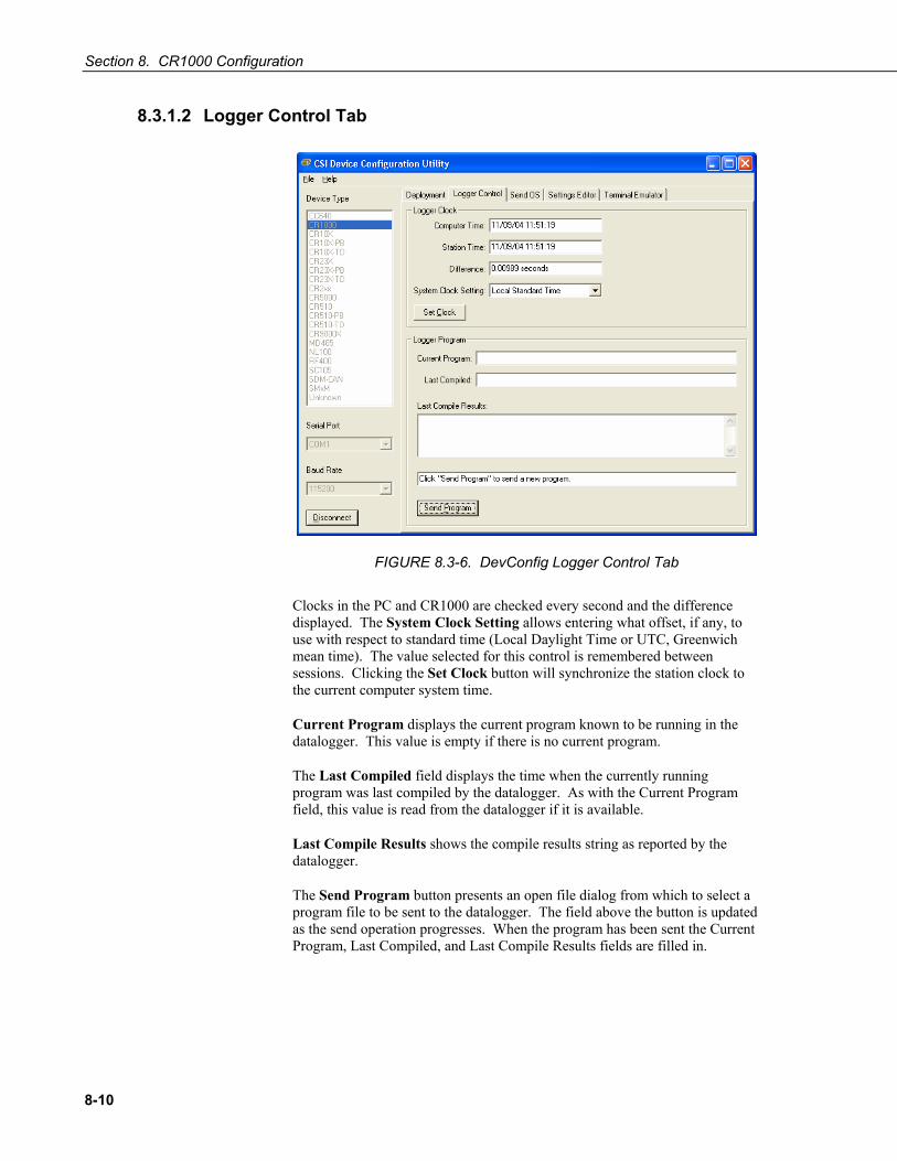
Section 8. CR1000 Configuration
8-10
8.3.1.2 Logger Control Tab
FIGURE 8.3-6. DevConfig Logger Control Tab
Clocks in the PC and CR1000 are checked every second and the difference displayed. The System Clock Setting allows entering what offset, if any, to use with respect to standard time (Local Daylight Time or UTC, Greenwich mean time). The value selected for this control is remembered between sessions. Clicking the Set Clock button will synchronize the station clock to the current computer system time.
Current Program displays the current program known to be running in the datalogger. This value is empty if there is no current program.
The Last Compiled field displays the time when the currently running program was last compiled by the datalogger. As with the Current Program field, this value is read from the datalogger if it is available.
Last Compile Results shows the compile results string as reported by the datalogger.
The Send Program button presents an open file dialog from which to select a program file to be sent to the datalogger. The field above the button is updated as the send operation progresses. When the program has been sent the Current Program, Last Compiled, and Last Compile Results fields are filled in.
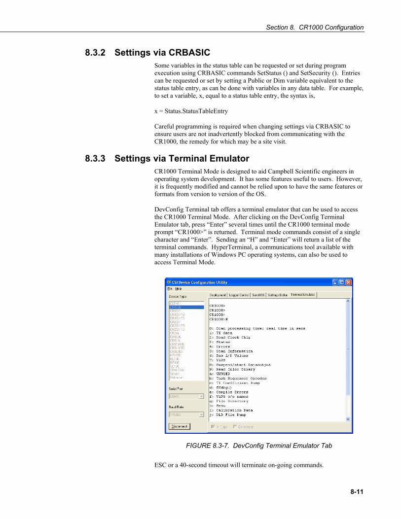
Section 8. CR1000 Configuration
8-11
8.3.2 Settings via CRBASIC Some variables in the status table can be requested or set during program execution using CRBASIC commands SetStatus () and SetSecurity (). Entries can be requested or set by setting a Public or Dim variable equivalent to the status table entry, as can be done with variables in any data table. For example, to set a variable, x, equal to a status table entry, the syntax is,
x = Status.StatusTableEntry
Careful programming is required when changing settings via CRBASIC to ensure users are not inadvertently blocked from communicating with the CR1000, the remedy for which may be a site visit.
8.3.3 Settings via Terminal Emulator CR1000 Terminal Mode is designed to aid Campbell Scientific engineers in operating system development. It has some features useful to users. However, it is frequently modified and cannot be relied upon to have the same features or formats from version to version of the OS.
DevConfig Terminal tab offers a terminal emulator that can be used to access the CR1000 Terminal Mode. After clicking on the DevConfig Terminal Emulator tab, press “Enter” several times until the CR1000 terminal mode prompt “CR1000>” is returned. Terminal mode commands consist of a single character and “Enter”. Sending an “H” and “Enter” will return a list of the terminal commands. HyperTerminal, a communications tool available with many installations of Windows PC operating systems, can also be used to access Terminal Mode.
FIGURE 8.3-7. DevConfig Terminal Emulator Tab
ESC or a 40-second timeout will terminate on-going commands.

Section 8. CR1000 Configuration
8-12
8.3.4 Durable Settings Many CR1000 settings can be changed remotely over a telecommunications link either directly or as part of the CRBASIC program. This convenience comes with the risk of inadvertently changing settings and disabling communications. Such an instance will likely require an on-site visit to correct the problem. For example, digital cell modems are often controlled by the switched 12 Volt (SW-12) channel. SW-12 is normally off, so, if the program controlling SW-12 is disabled, such as by replacing it with a program that neglects SW-12 control, the cell modem is switched off and the remote CR1000 drops out of telecommunications.
Campbell Scientific recommends implementing one or both of the provisions described in Sectons 8.3.4.1 and 8.3.4.2 to help preserve remote communication, or other vital settings.
8.3.4.1 “Include” File The Include file is a CRBASIC program file that resides in CR1000 memory and compiles as an add-on to the user entered program. The Include file begins with the SlowSequence instruction and contains code to set essential telecommunications or other settings. This feature is enabled by sending the Include file to the CR1000 using the File Contol feature, then entering the path and name of the file in the Include file setting in the CR1000 using DevConfig or PakBusGraph. There is no restriction on the length of the Include file. EXAMPLE 8.3-1 shows a program that expects an Include file to control power to a modem; EXAMPLE 8.3-2 lists the Include file code.
EXAMPLE 8.3-1. CRBASIC Code: A simple main program wherein the programmer expects an Include file to be activated.
'Include Example.CR1 – Main Program 'Assumes that an Include file is loaded onto the CR1000 CPU: Drive 'The Include file will control power to the cellular phone modem. Public PTemp, batt_volt DataTable (Test,1,-1) DataInterval (0,15,Sec,10) Minimum (1,batt_volt,FP2,0,False) Sample (1,PTemp,FP2) EndTable BeginProg Scan (1,Sec,0,0) PanelTemp (PTemp,250) Battery (Batt_volt) CallTable Test NextScan '<<<<<<<<<<<<<<<<<<<<<<<<<<<Include File Code Executed Here EndProg

Section 8. CR1000 Configuration
8-13
EXAMPLE 8.3-2. CRBASIC Code: A simple Include file to control SW-12 switched power terminal.
'Include File.CR1 – “Add-on” Program ‘Control Cellular modem power for the main program. 'Cell phone + to be wired to SW-12 terminal, - to G. '<<<<<<<<<<<<<<<<<<<<<<<<<<<No BeginProg Instruction!! SlowSequence Scan (1,Sec,0,0) If TimeIntoInterval (9,24,Hr) Then SW12 (1) ‘Modem on at 9:00 AM If TimeIntoInterval (17,24,Hr) Then SW12 (0) ‘Modem off at 5:00 PM NextScan '<<<<<<<<<<<<<<<<<<<<<<<<<<<No EndProg Instruction!!
FIGURE 8.3-8. CR1000 “Include File” settings via DevConfig.

Section 8. CR1000 Configuration
8-14
FIGURE 8.3-9. “Include File” settings via LoggerNet | PakBusGraph – provides a settings portal via telecommunications.
8.3.4.2 Default.CR1 File Default.CR1 can be stored on the CR1000 CPU: drive. At power up, the CR1000 looks for and, when it exists, loads default.CR1 if no other program takes priority (see Section 8.3.4.3 Priorities). Default.CR1 cannot be more than a few lines of code.
EXAMPLE 8.3-3. CRBASIC Code: A simple Default.CR1 file to control SW-12 switched power terminal.
BeginProg Scan (1,Sec,0,0) If TimeIntoInterval (15,60,Sec) Then SW12 (1) If TimeIntoInterval (45,60,Sec) Then SW12 (0) NextScan EndProg
8.3.4.3 Priorities 1) When the CR1000 powers up, the program file (.CR1) marked as “Run On
Power-up” or “Run Always” or “Run Now” (order of priority) becomes the current program.
2) If there is a file specified in the Include File Name setting, it is compiled at the end of the program selected in 1).

Section 8. CR1000 Configuration
8-15
3) If there is no file selected in 1), or if the selected file cannot be compiled, the CR1000 will run the program listed in the Include File Name setting.
4) If the program listed in the Include File Name setting cannot be run or if no program is specified, the CR1000 will attempt to run the program named default.cr1 on its CPU: drive.
5) If there is no default.cr1 file or it cannot be compiled, the CR1000 will not currently run any program.

Section 8. CR1000 Configuration
8-16
9-1
Section 9. Programming 9.1 Inserting Comments into Program
Comments are non-functioning text placed within the body of a program to document or clarify program algorithms.
As shown in EXAMPLE 9.1-1, comments are inserted into a program by preceding the comment with a single quote ('). Comments can be entered either as independent lines or following CR1000 code. When the CR1000 compiler sees a single quote ('), it ignores the rest of the line.
EXAMPLE 9.1-1. CRBASIC Code: Inserting Comments
'Declaration of variables starts here. Public Start(6) 'Declare the start time array
9.2 Sending Programs The CR1000 requires a program be sent to its memory to direct measurement, processing, and data storage operations. Programs are sent with LoggerNet / PC400 / RTDAQ / PC200W datalogger support software. Programs can also be sent from Device Configuration Utility (DevConfig) or a CF card. A good practice is to always retrieve data from the CR1000 before sending a program, otherwise, data may be lost.
Read More! See 12.5 File Management and the CF card storage module manual.
9.2.1 Preserving Data at Program Send When sending programs to the CR1000 through software options listed in TABLE 9.2-1, memory is reset and data are erased.
TABLE 9.2-1. Program Send Options that Reset Memory1
LoggerNet | Connect | Program Send
PC400 | Clock/Program | Send Program
PC200W | Clock/Program | Send Program
RTDAQ | Clock/Program | Send Program
DevConfig | Logger Control | Send Program 1Reset memory and set program attributes to Run Always
When data retention is desired, use LoggerNet / PC400 / RTDAQ File Control | Send, or CRBASIC Editor option Compile | Compile, Save, Send to send programs. Using these options first requires a telecommunications link be set up in LoggerNet / PC400 / RTDAQ. The window shown in FIGURE 9.2-1 is

Section 9. CR1000 Programming
9-2
displayed before the program is sent. Select “Run Now”, “Run On Power-up”, and “Do not erase the card data files” before pressing Send.
To retain data, “Do not erase the card data files” must be selected whether or not a CF card storage module is present.
FIGURE 9.2-1. CRBASIC Editor Program Send File Control Window
Regardless of the program upload tool used, if any change occurs to data table structures listed in TABLE 9.2-2. Data Table, data will be erased when a new program is sent.
TABLE 9.2-2. Data Table Structures
--Data table name(s)
--Data interval or offset
--Number of fields per record
--Number of bytes per field
--Field type, size, name, or position
--Number of records in table
9.3 Writing Programs Programs are created with either Short Cut, CRBASIC Editor, or Transformer. Short Cut is available at no charge at www.campbellsci.com. CRBASIC Editor and Transformer are programs in LoggerNet / PC400 datalogger support software suites. Programs can be up to 490 kbytes in size although typical programs are much smaller.
NOTE

Section 9. CR1000 Programming
9-3
“Transformer”, a utility included with PC400 and LoggerNet Software, converts most CR10X datalogger code to CR1000 datalogger code.
9.3.1 Short Cut Editor and Program Generator Short Cut is easy-to-use menu-driven software that presents the user with lists of predefined measurement, processing, and control algorithms from which to choose. The user makes choices and Short Cut writes the CRBASIC code required to perform the tasks. Short Cut creates a wiring diagram to simplify connection of sensors and external devices. Section 2, Quickstart Tutorial, works through a measurement example using Short Cut.
For many complex applications, Short Cut is still a good place to start. When as much information as possible is entered, Short Cut will create a program template from which to work, already formatted with most of the proper structure, measurement routines, and variables. The program can then be edited further using CRBASIC Program Editor.
9.3.2 CRBASIC Editor CR1000 application programs are written in a variation of BASIC (Beginner’s All-purpose Symbolic Instruction Code) computer language, CRBASIC (Campbell Recorder BASIC). CRBASIC Editor is a text editor that facilitates creation and modification of the ASCII text file that constitutes the CR1000 application program. CRBASIC Editor is available as part of LoggerNet / PC400 / RTDAQ datalogger support software packages.
Fundamental elements of CRBASIC include:
• Variables – named packets of CR1000 memory into which are stored values that normally vary during program execution. Values are typically the result of measurements and processing. Variables are given an alphanumeric name and can be dimensioned into arrays of related data.
• Constants – discrete packets of CR1000 memory into which are stored specific values that do not vary during program executions. Constants are given alphanumeric names and assigned values at the beginning declarations of a CRBASIC program.
Keywords and predefined constants are reserved for internal CR1000 use. If a user programmed variable happens to be a keyword or predefined constant, a runtime or compile error will occur. To correct the error, simply change the variable name by adding or deleting one or more letters, numbers, or the underscore (_) from the variable name, then recompile and resend the program. CRBASIC Help provides a list of keywords and pre-defined constants.
• Common instructions – Instructions and operators used in most BASIC languages, including program control statements, and logic and mathematical operators.
• Special instructions – Instructions unique to CRBASIC, including measurement instructions that access measurement channels, and
NOTE
NOTE

Section 9. CR1000 Programming
9-4
processing instructions that compress many common calculations used in CR1000 dataloggers.
These four elements must be properly placed within the program structure.
9.3.3 Transformer This section is not yet available.
9.4 Numerical Formats Four numerical formats are supported by CRBASIC. Most common is the use of base 10 numbers. Scientific notation, binary, and hexadecimal formats may also be used, as shown in TABLE 9.4-1. Only standard base 10 notation is supported by Campbell Scientific hardware and software displays.
TABLE 9.4-1. Formats for Entering Numbers in CRBASIC
Format Example Base 10 Equivalent Value Standard 6.832 6.832 Scientific notation 5.67E-8 5.67X10⁻⁸ Binary &B1101 11 Hexadecimal &HFF 255
Binary format is useful when loading the status (1 = high, 0 = low) of multiple flags or ports into a single variable, e.g., storing the binary number &B11100000 preserves the status of flags 8 through 1. In this case, flags 1 - 5 are low, 6 - 8 are high. Program Code EXAMPLE 9.4-1 shows an algorithm that loads binary status of flags into a LONG integer variable.
EXAMPLE 9.4-1. CRBASIC Code: Program to load binary information into a single variable.
Public FlagInt As Long Public Flag(8) As Boolean Public I DataTable (FlagOut,True,-1) Sample (1,FlagInt,UINT2) EndTable BeginProg Scan (1,Sec,3,0) FlagInt = 0 For I = 1 To 8 If Flag(I) = true then FlagInt = FlagInt + 2 ^ (I - 1) EndIf Next I CallTable FlagOut NextScan EndProg
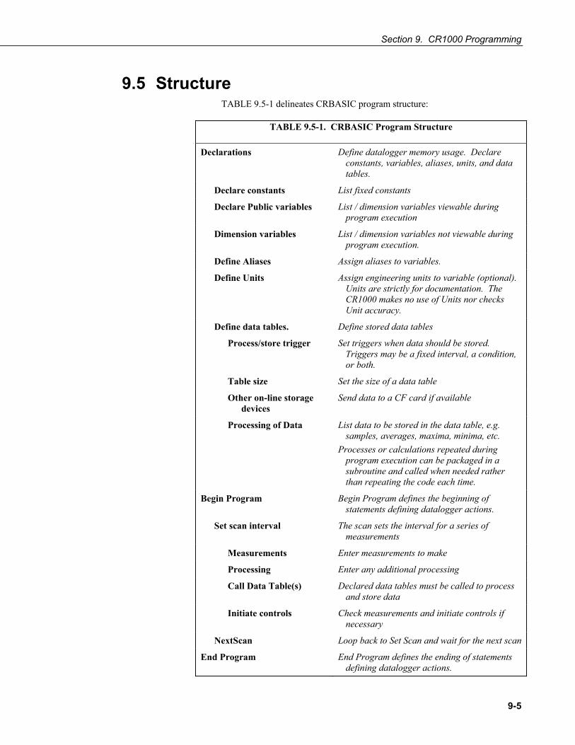
Section 9. CR1000 Programming
9-5
9.5 Structure TABLE 9.5-1 delineates CRBASIC program structure:
TABLE 9.5-1. CRBASIC Program Structure
Declarations Define datalogger memory usage. Declare constants, variables, aliases, units, and data tables.
Declare constants List fixed constants
Declare Public variables List / dimension variables viewable during program execution
Dimension variables List / dimension variables not viewable during program execution.
Define Aliases Assign aliases to variables.
Define Units Assign engineering units to variable (optional). Units are strictly for documentation. The CR1000 makes no use of Units nor checks Unit accuracy.
Define data tables. Define stored data tables
Process/store trigger Set triggers when data should be stored. Triggers may be a fixed interval, a condition, or both.
Table size Set the size of a data table
Other on-line storage devices
Send data to a CF card if available
Processing of Data List data to be stored in the data table, e.g. samples, averages, maxima, minima, etc.
Processes or calculations repeated during program execution can be packaged in a subroutine and called when needed rather than repeating the code each time.
Begin Program Begin Program defines the beginning of statements defining datalogger actions.
Set scan interval The scan sets the interval for a series of measurements
Measurements Enter measurements to make
Processing Enter any additional processing
Call Data Table(s) Declared data tables must be called to process and store data
Initiate controls Check measurements and initiate controls if necessary
NextScan Loop back to Set Scan and wait for the next scan
End Program End Program defines the ending of statements defining datalogger actions.

Section 9. CR1000 Programming
9-6
EXAMPLE 9.5-1 demonstrates the proper structure of a CRBASIC program.
EXAMPLE 9.5-1. CRBASIC Code: Proper Program Structure
‘Declarations ‘Define constants Const RevDiff=1 Const Del=0 'default Const Integ=250 Const Mult=1 Const Offset=0 ‘Define public variables Public RefTemp Public TC(6) ‘Define units Units RefTemp=degC Units TC=DegC ‘Define data tables DataTable (Temp,1,2000) DataInterval (0,10,min,10) Average (1,RefTemp,FP2,0) Average (6,TC(),FP2,0) EndTable ‘Begin Program BeginProg ‘Set scan interval Scan (1,Sec,3,0) ‘Measurements PanelTemp (RefTemp, 250) TCDiff (TC(),6,mV2_5C ,1,TypeT,RefTemp,RevDiff,Del,Integ,Mult,Offset) ‘Processing (None) ‘Call data table CallTable Temp ‘Initiate controls (None) ‘Loop to next scan NextScan ‘End Program End Prog
Declare constants
Declare public variables, dimension array, and declare units.
Define Data Table
Declarations
Call Data Table
Scan loop
Measure

Section 9. CR1000 Programming
9-7
9.6 Declarations I – Single-line Declarations Public variables, Dim variables, Constants, Units, Aliases, Station Name, Data Tables and Subroutines are declared at the beginning of a CRBASIC program. Table 9.10-1 lists declaration names and allowed lengths
9.6.1 Variables A variable is a packet of memory, given an alphanumeric name, through which pass measurements and processing results during program execution. Variables are declared either as Public or Dim at the discretion of the programmer. Public variables can be viewed through the CR1000KD or software numeric monitors. Dim variables cannot.
9.6.1.1 Arrays When a variable is declared, several variables of the same root name can also be declared. This is done by placing a suffix of “(x)” on the alphanumeric name, which creates an array of x number of variables that differ only by the incrementing number in the suffix. For example, rather than declaring four similar variables as follows,
Public TempC1 Public TempC2 Public TempC3 Public TempC4
simply declare a variable array as shown below:
Public TempC(4),
This creates in memory the four variables TempC(1), TempC(2), TempC(3), and TempC(4).
A variable array is useful in program operations that affect many variables in the same way. EXAMPLE 9.6-1 shows program code using a variable array to reduce the amount of code required to convert four temperatures from Celsius degrees to Fahrenheit degrees.
EXAMPLE 9.6-1. CRBASIC Code: Using a variable array in calculations.
Public TempC(4) Public TempF(4) Dim T BeginProg Scan (1,Sec,0,0) Therm107 (TempC(),4,1,Vx1,0,250,1.0,0) For T = 1 To 4 TempF(T) = TempC(T) * 1.8 + 32 Next NextScan EndProg

Section 9. CR1000 Programming
9-8
9.6.1.2 Dimensions Occasionally, a multi-dimensioned array is required by an application. Dimensioned arrays can be thought of just as distance, area, and volume measurements are thought of. A single dimensioned array, declared as VariableName(x), with (x) being the index, can be thought of as x number of variables is a series. A two-dimensional array, declared as
Public (or Dim) VariableName(x,y),
with (x,y) being the indicies, can be thought of as (x) * (y) number of variables in a square x-by-y matrix. Three-dimensional arrays (VariableName (x,y,z), (x,y,z) being the indicies) have (x) * (y) * (z) number of variables in a cubic x-by-y-by-z matrix. Dimensions greater than three are not permitted by CRBASIC. Strings can be declared at a maximum of two dimensions. The third dimension is used internally for accessing characters within a string.
When using variables in place of integers as the dimension indicies, e.g. EXAMPLE 9.6-2, declaring the indicies as Long variables is recommended as doing so allows for much more efficient use of CR1000 resources.
EXAMPLE 9.6-2. CRBASIC Code: Using Variable Array Dimension Indicies
Dim aaa As Long Dim bbb As Long Dim ccc As Long Public VariableName(4,4,4) as Float BeginProg Scan() aaa = 3 bbb = 2 ccc = 4 VariableName(aaa,bbb,ccc) = 2.718 NextScan EndProg
9.6.1.3 Data Types Variables and stored data can be configured with various data types to optimize program execution and memory usage.
The declaration of variables (via the DIM or the PUBLIC statement) allows an optional type descriptor AS that specifies the data type. The default data type, without a descriptor, is IEEE4 floating point (FLOAT). Variable data types are STRING and three numeric types: FLOAT, LONG, and BOOLEAN. Stored data has additional data type options FP2, UINT2, BOOL8, and NSEC. EXAMPLE 9.6-3 shows these in use in the declarations and output sections of a CRBASIC program.
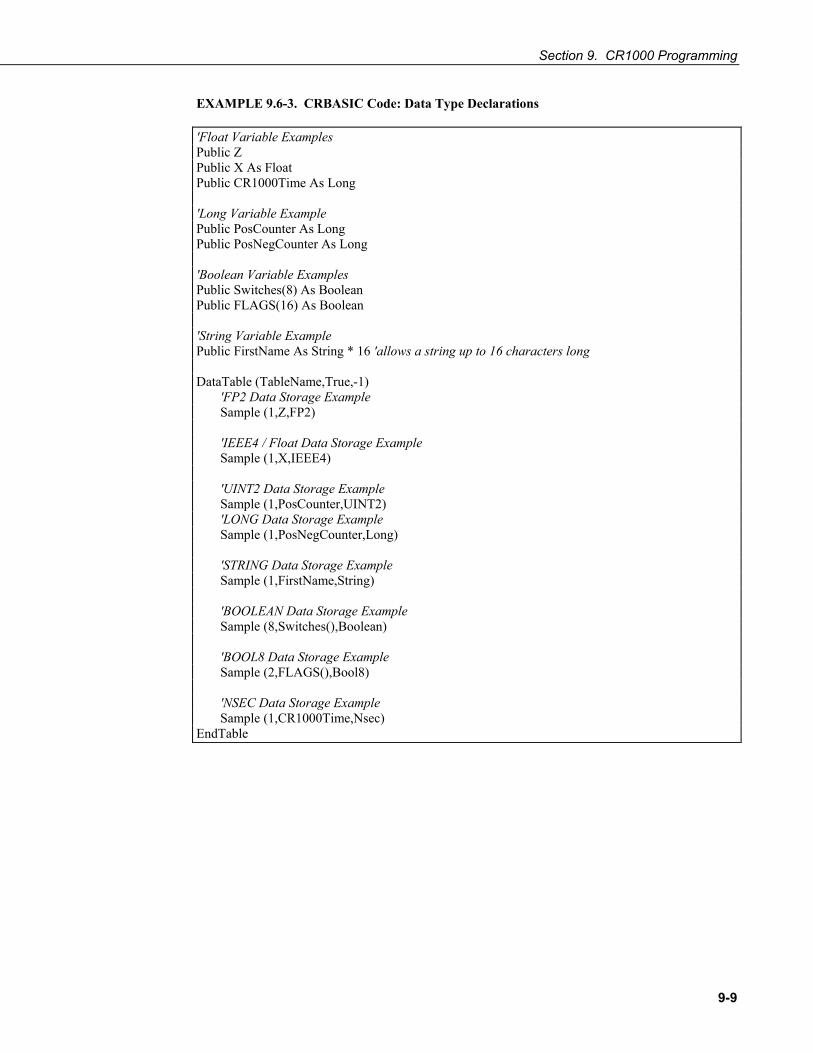
Section 9. CR1000 Programming
9-9
EXAMPLE 9.6-3. CRBASIC Code: Data Type Declarations
'Float Variable Examples Public Z Public X As Float Public CR1000Time As Long 'Long Variable Example Public PosCounter As Long Public PosNegCounter As Long 'Boolean Variable Examples Public Switches(8) As Boolean Public FLAGS(16) As Boolean 'String Variable Example Public FirstName As String * 16 'allows a string up to 16 characters long DataTable (TableName,True,-1) 'FP2 Data Storage Example Sample (1,Z,FP2) 'IEEE4 / Float Data Storage Example Sample (1,X,IEEE4) 'UINT2 Data Storage Example Sample (1,PosCounter,UINT2) 'LONG Data Storage Example Sample (1,PosNegCounter,Long) 'STRING Data Storage Example Sample (1,FirstName,String) 'BOOLEAN Data Storage Example Sample (8,Switches(),Boolean) 'BOOL8 Data Storage Example Sample (2,FLAGS(),Bool8) 'NSEC Data Storage Example Sample (1,CR1000Time,Nsec) EndTable

Section 9. CR1000 Programming
9-10
TABLE 9.6-1 lists details of available data types.
TABLE 9.6-1. Data Types
Code Data Format Where Used Word Size Range Resolution
FP2 Campbell Scientific Floating Point
Output Data Storage Only
2 bytes ±7999 13 bits (about 4 digits)
IEEE4 or FLOAT
IEEE 4 Byte Floating Point
Output Data Storage / Variables
4 bytes ±1.4 x 10-45 to ±3.4 x 1038
24 bits (about 7 digits)
LONG 4 Byte Signed Integer
Output Data Storage / Variables
4 bytes -2,147,483,648 to +2,147,483,647
1 bit (1)
UINT2 2 Byte Unsigned Integer
Output Data Storage Only
2 bytes 0 to 65535 1 bit (1)
BOOLEAN 4 byte Signed Integer
Output Data Storage / Variables
4 bytes 0, -1 True or False (-1 or 0)
BOOL8 1 byte Boolean Output Data Storage Only
1 byte 0, -1 True or False (-1 or 0)
NSEC Time Stamp Output Data Storage Only
8 byte seconds since 1990 nanosecond
STRING ASCII String Output Data Storage / Variables
Set by program
9.6.1.4 Data Type Operational Detail FLOAT 4 byte floating point data type. Default CR1000 data type for Public
or Dim variables. Same format as IEEE4. IEEE4 is the name used when declaring data type for stored data table data.
FP2 2 byte floating point data type. Default CR1000 data type for stored data. While IEEE 4 byte floating point is used for variables and internal calculations, FP2 is adequate for most stored data. FP2 provides 3 or 4 significant digits of resolution, and requires half the memory as IEEE 4.
TABLE 9.6-2. Resolution and Range Limits of FP2 Data
Zero Minimum Magnitude Maximum Magnitude 0.000 ±0.001 ±7999.
The resolution of FP2 is reduced to 3 significant digits when the first
(left most) digit is 8 or greater (TABLE 9.6-2). Thus, it may be necessary to use IEEE4 format or an offset to maintain the desired resolution of a measurement. For example, if water level is to be
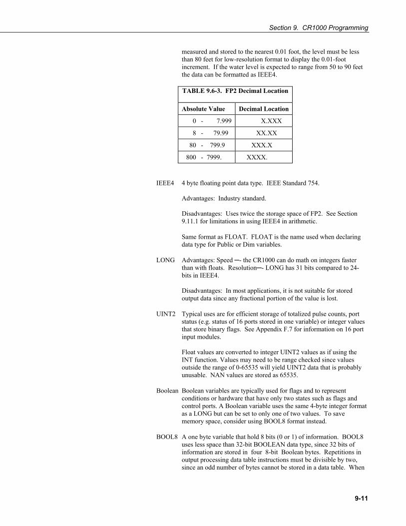
Section 9. CR1000 Programming
9-11
measured and stored to the nearest 0.01 foot, the level must be less than 80 feet for low-resolution format to display the 0.01-foot increment. If the water level is expected to range from 50 to 90 feet the data can be formatted as IEEE4.
TABLE 9.6-3. FP2 Decimal Location
Absolute Value Decimal Location
0 - 7.999 X.XXX
8 - 79.99 XX.XX
80 - 799.9 XXX.X
800 - 7999. XXXX.
IEEE4 4 byte floating point data type. IEEE Standard 754. Advantages: Industry standard. Disadvantages: Uses twice the storage space of FP2. See Section 9.11.1 for limitations in using IEEE4 in arithmetic.
Same format as FLOAT. FLOAT is the name used when declaring data type for Public or Dim variables.
LONG Advantages: Speed - the CR1000 can do math on integers faster than with floats. Resolution- LONG has 31 bits compared to 24-bits in IEEE4. Disadvantages: In most applications, it is not suitable for stored output data since any fractional portion of the value is lost.
UINT2 Typical uses are for efficient storage of totalized pulse counts, port status (e.g. status of 16 ports stored in one variable) or integer values that store binary flags. See Appendix F.7 for information on 16 port input modules. Float values are converted to integer UINT2 values as if using the INT function. Values may need to be range checked since values outside the range of 0-65535 will yield UINT2 data that is probably unusable. NAN values are stored as 65535.
Boolean Boolean variables are typically used for flags and to represent conditions or hardware that have only two states such as flags and control ports. A Boolean variable uses the same 4-byte integer format as a LONG but can be set to only one of two values. To save memory space, consider using BOOL8 format instead.
BOOL8 A one byte variable that hold 8 bits (0 or 1) of information. BOOL8 uses less space than 32-bit BOOLEAN data type, since 32 bits of information are stored in four 8-bit Boolean bytes. Repetitions in output processing data table instructions must be divisible by two, since an odd number of bytes cannot be stored in a data table. When

Section 9. CR1000 Programming
9-12
converting from a LONG or a FLOAT to a BOOL8, only the least significant 8 bits are used, i.e., only the modulo 256 is used. When LoggerNet / PC400 / RTDAQ / PC200W retrieves a BOOL8 data type, it splits it apart into 8 fields of true or false when displaying or storing to an ASCII file. Consequently, more computer memory is consumed by the datalogger support software, but CR1000 memory is conserved. Conservation of memory in the CR1000 also results in less band width being used when data are collected via telecommunications.
Read More! Bool8 data type is discussed in depth, with examples, in Section 11.12.
NSEC 8 bytes divided up as 4 bytes of seconds since 1990 and 4 bytes of nanoseconds into the second. Used when a LONG variable being sampled is the result of the RealTime() instruction or when the sampled variable is a LONG storing time since 1990, such as when time of maximum or time of minimum is asked for. Alternatively, if the variable array (must be FLOAT or LONG) is dimensioned to 7, the values stored are year, month, day of year, hour, minutes, seconds, and milliseconds. If the variable array (must be LONG) is dimensioned to two, the instruction assumes the first element holds seconds since 1990 and the second element holds microseconds into the second. If the variable array (must be LONG) is dimensioned to 1, the instruction assumes that the variable holds seconds since 1990 and microseconds into the second is 0. In this instance, the value stored is a standard datalogger timestamp rather than the number of seconds since January 1990.
Read More! NSEC data type is discussed in depth, with examples, in Section 11.11.
String ASCII String; size defined by the CR1000 CRBASIC program. If declared as “MyString * 1”, string size is 1 byte or character. Otherwise, the minimum string datum size (regardless of word length), and the default if size is not specified, is 16 bytes or characters. Memory allocation above 16 bytes increases in multiples of 4 bytes; e.g., String * 18 allocates 20 bytes (19 usable). A string conveniently handles alphanumeric variables associated with serial sensors, dial strings, text messages, etc.
9.6.1.5 Flags Flags are a useful program control tool. While any variable of any data type can be used as a flag, using Boolean variables, especially variables named “Flag”, works best. EXAMPLE 9.6-4 shows an example using flags to change the word in string variables.

Section 9. CR1000 Programming
9-13
EXAMPLE 9.6-4. CRBASIC Code: Flag Declaration and Use
Public Flag(2) As Boolean Public FlagReport(2) As String BeginProg Scan (1,Sec,0,0) If Flag(1) = True Then FlagReport(1) = "High" Else FlagReport(1) = "Low" EndIf If Flag(2) = True Then FlagReport(2) = "High" Else FlagReport(2) = "Low" EndIf NextScan EndProg
9.6.2 Constants A constant can be declared at the beginning of a program to assign an alphanumeric name to be used in place of a value so the program can refer to the name rather than the value itself. Using a constant in place of a value can make the program easier to read and modify, and more secure against unintended changes. Constants can be changed while the program is running if they are declared using the ConstTable/EndConstTable instruction.
Programming Tip: Using all uppercase for constant names may make them easier to recognize.
EXAMPLE 9.6-5. CRBASIC Code: Using the Const Declaration.
Public PTempC, PTempF Const CtoF_Mult = 1.8 Const CtoF_Offset = 32 BeginProg Scan (1,Sec,0,0) PanelTemp (PTempC,250) PTempF = PTempC * CtoF_Mult + CtoF_Offset NextScan EndProg
9.6.2.1 Predefined Constants Several words are reserved for use by CRBASIC. These words cannot be used as variable or table names in a program. Predefined constants include some instruction names, as well as valid alphanumeric names for instruction parameters. In general, instruction names should not be used as variable, constant, or table names in a datalogger program, even if they are not specifically listed as a predefined constant. If predefined constant is used in a

Section 9. CR1000 Programming
9-14
program, an error similar to that shown in FIGURE 9.6-1 may, but not always, be displayed. TABLE 9.6-4 lists predefined constants.
STRING is already in use as a predefined CONST
FIGURE 9.6-1. Predefined CONST Error
TABLE 9.6-4. Predefined Constants and Reserved Words
_50hz _60hz Auto Autoc
AutoRange AutoRangec BOOL8 BOOLEAN
CAO1 CAO2 Case Com1
Com2 Com3 Com310 Com4
ComME ComRS232 ComSDC10 ComSDC11
ComSDC7 ComSDC8 CR1000 CR3000
CR5000 CR800 CR9000X day
DO EVENT FLOAT FOR
hr FALSE If IX1
IX2 IEEE4 IX4 LoggerType
LONG IX3 msec mv1000
mv1000C min mv1000R mv2_5
mv2_5c mv1000cR mv200 mv200c
mv200cR mv20 mv20c mv25
mv250 mv200R mv2500c mv250c
mv25c mv2500 mv500 mv5000
mv5000 mv50 mv5000C mv5000cR
mv5000R mv5000c mv50c mv50c
mv50cR mv500c mv7_5 mv7_5c
mvX10500 mv50R NSEC PROG
SCAN mvX1500 Select STRING
SUB sec TABLE TRUE
TypeB SUBSCAN TypeJ TypeK
TypeN TypeE TypeS TypeT
UINT2 TypeR usec v10
v2 Until v2c v50
v60 v20 VX1 (VX1 (EX1)) vX15
VX2 VX1 vX105 VX2 (EX2)
VX3 (EX3) VX3 VX4 While

Section 9. CR1000 Programming
9-15
9.6.3 Alias and Unit Declarations Each variable can be assigned a second name, or alias, by which it can be called throughout the program. Aliasing is particularly useful when using arrays. Arrays are powerful features in complex programs, but place the same appellation on a number of variables. The use of an alias allows the power of the array to be used with the clarity of unique names.
Each variable can be assigned units to clarify the meaning. Units are not used elsewhere in programming, but rather add meaning to resultant data table headers.
9.7 Declarations II – Declared Sequences Declaration sequences include DataTable / EndTable and Sub / EndSub. Certain sequences incidental to a specific datalogger application also need to be declared. These include ShutDown / ShutdownEnd, DialSequence / EndDialSequence, ModemHangup / EndModemHangup, and WebPageBegin / WebPageEnd sequences. Declaration sequences can be located:
a) prior to BeginProg
b) after EndSequence or an infinite Scan / NextScan and before EndProg or SlowSequence
c) immediately following SlowSequence
SlowSequence code starts executing after any declaration sequence. Only declaration sequences can occur after EndSequence and before SlowSequence or EndProg.
9.7.1 Data Tables Data are stored in tables as directed by the CRBASIC program. A data table is created by a series of CRBASIC instructions entered after variable declarations but before the BeginProg instruction. These instructions include:
DataTable () Output Trigger Condition(s) Output Processing Instructions EndTable
A data table is essentially a file that resides in CR1000 memory. The file is written to each time data are directed to that file. The trigger that initiates data storage is tripped either by the CR1000’s clock, or by an event, such as a high temperature. Up to 30 data tables can be created by the program. The data tables may store individual measurements, individual calculated values, or summary data such as averages, maxima, or minima to data tables.
Each data table is associated with overhead information that becomes part of the ASCII file header when data are downloaded to a PC. Overhead information includes:
• table format • datalogger type and operating system version, • name of the CRBASIC program running in the datalogger
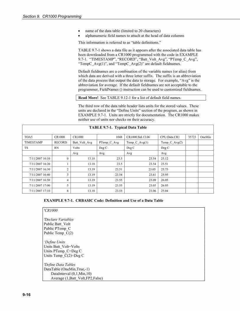
Section 9. CR1000 Programming
9-16
• name of the data table (limited to 20 characters) • alphanumeric field names to attach at the head of data columns
This information is referred to as “table definitions.”
TABLE 9.7-1 shows a data file as it appears after the associated data table has been downloaded from a CR1000 programmed with the code in EXAMPLE 9.7-1. “TIMESTAMP”, “RECORD”, “Batt_Volt_Avg”, “PTemp_C_Avg”, “TempC_Avg(1)”, and “TempC_Avg(2)” are default fieldnames.
Default fieldnames are a combination of the variable names (or alias) from which data are derived with a three letter suffix. The suffix is an abbreviation of the data process that output the data to storage. For example, “Avg” is the abbreviation for average. If the default fieldnames are not acceptable to the programmer, FieldNames () instruction can be used to customized fieldnames.
Read More! See TABLE 9.12-1 for a list of default field names.
The third row of the data table header lists units for the stored values. These units are declared in the “Define Units” section of the program, as shown in EXAMPLE 9.7-1. Units are strictly for documentation. The CR1000 makes neither use of units nor checks on their accuracy.
TABLE 9.7-1. Typical Data Table
TOA5 CR1000 CR1000 1048 CR1000.Std.13.06 CPU:Data.CR1 35723 OneMin
TIMESTAMP RECORD Batt_Volt_Avg PTemp_C_Avg Temp_C_Avg(1) Temp_C_Avg(2)
TS RN Volts Deg C Deg C Deg C
Avg Avg Avg Avg
7/11/2007 16:10 0 13.18 23.5 23.54 25.12
7/11/2007 16:20 1 13.18 23.5 23.54 25.51
7/11/2007 16:30 2 13.19 23.51 23.05 25.73
7/11/2007 16:40 3 13.19 23.54 23.61 25.95
7/11/2007 16:50 4 13.19 23.55 23.09 26.05
7/11/2007 17:00 5 13.19 23.55 23.05 26.05
7/11/2007 17:10 6 13.18 23.55 23.06 25.04
EXAMPLE 9.7-1. CRBASIC Code: Definition and Use of a Data Table
'CR1000 'Declare Variables Public Batt_Volt Public PTemp_C Public Temp_C(2) ‘Define Units Units Batt_Volt=Volts Units PTemp_C=Deg C Units Temp_C(2)=Deg C 'Define Data Tables DataTable (OneMin,True,-1) DataInterval (0,1,Min,10) Average (1,Batt_Volt,FP2,False)

Section 9. CR1000 Programming
9-17
Average (1,PTemp_C,FP2,False) Average (2,Temp_C(1),FP2,False) EndTable DataTable (Table1,True,-1) DataInterval (0,1440,Min,0) Minimum (1,Batt_Volt,FP2,False,False) EndTable 'Main Program BeginProg Scan (5,Sec,1,0) 'Default Datalogger Battery Voltage measurement Batt_Volt: Battery (Batt_Volt) 'Wiring Panel Temperature measurement PTemp_C: PanelTemp (PTemp_C,_60Hz) 'Type T (copper-constantan) Thermocouple measurements Temp_C: TCDiff (Temp_C(),2,mV2_5C,1,TypeT,PTemp_C,True,0,_60Hz,1,0) 'Call Data Tables and Store Data CallTable (OneMin) CallTable (Table1) NextScan EndProg
As shown in EXAMPLE 9.7-1, data table declaration begins with the DataTable () instruction and ends with the EndTable () instruction. Between DataTable () and EndTable () are instructions that define what data to store and under what conditions data are stored. A data table must be called by the CRBASIC program for data storage processing to occur. Typically, data tables are called by the CallTable () instruction once each Scan.
9.7.1.1 DataTable () and EndTable () Instructions The DataTable instruction has three parameters: a user-specified alphanumeric name for the table (e.g., “OneMin”), a trigger condition (e.g., “True”), and the size to make the table in RAM (e.g., auto allocated).
• Name The table name can be any combination of numbers and letters up to 20 characters in length. The first character must be a letter.
• TrigVar – Controls whether or not data records are written to storage. Data records are written to storage if TrigVar is true and if other conditions, such as DataInterval (), are met. Default setting is -1 (True). TrigVar may be a variable, expression, or constant. TrigVar does not control intermediate processing. Intermediate processing is controlled by the disable variable, DisableVar, which is a parameter in all output processing instructions (see Section 9.7.1.4).
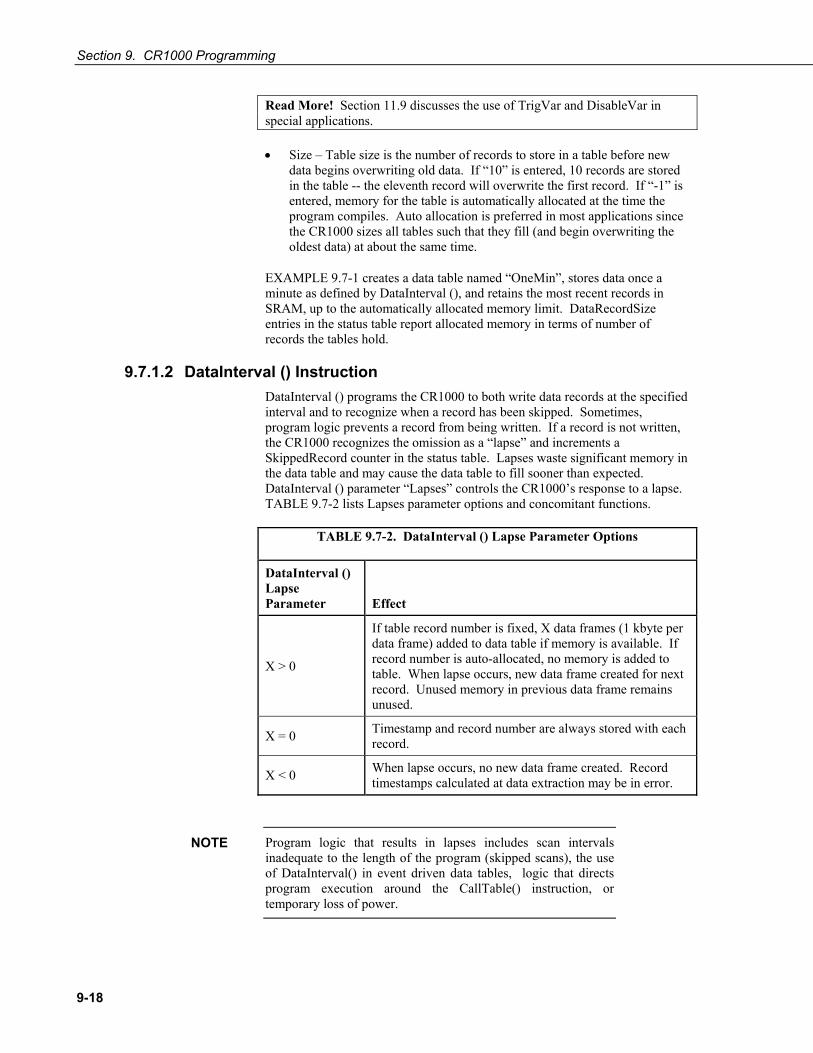
Section 9. CR1000 Programming
9-18
Read More! Section 11.9 discusses the use of TrigVar and DisableVar in special applications.
• Size – Table size is the number of records to store in a table before new data begins overwriting old data. If “10” is entered, 10 records are stored in the table -- the eleventh record will overwrite the first record. If “-1” is entered, memory for the table is automatically allocated at the time the program compiles. Auto allocation is preferred in most applications since the CR1000 sizes all tables such that they fill (and begin overwriting the oldest data) at about the same time.
EXAMPLE 9.7-1 creates a data table named “OneMin”, stores data once a minute as defined by DataInterval (), and retains the most recent records in SRAM, up to the automatically allocated memory limit. DataRecordSize entries in the status table report allocated memory in terms of number of records the tables hold.
9.7.1.2 DataInterval () Instruction DataInterval () programs the CR1000 to both write data records at the specified interval and to recognize when a record has been skipped. Sometimes, program logic prevents a record from being written. If a record is not written, the CR1000 recognizes the omission as a “lapse” and increments a SkippedRecord counter in the status table. Lapses waste significant memory in the data table and may cause the data table to fill sooner than expected. DataInterval () parameter “Lapses” controls the CR1000’s response to a lapse. TABLE 9.7-2 lists Lapses parameter options and concomitant functions.
TABLE 9.7-2. DataInterval () Lapse Parameter Options
DataInterval () Lapse Parameter Effect
X > 0
If table record number is fixed, X data frames (1 kbyte per data frame) added to data table if memory is available. If record number is auto-allocated, no memory is added to table. When lapse occurs, new data frame created for next record. Unused memory in previous data frame remains unused.
X = 0 Timestamp and record number are always stored with each record.
X < 0 When lapse occurs, no new data frame created. Record timestamps calculated at data extraction may be in error.
Program logic that results in lapses includes scan intervals inadequate to the length of the program (skipped scans), the use of DataInterval() in event driven data tables, logic that directs program execution around the CallTable() instruction, or temporary loss of power.
NOTE

Section 9. CR1000 Programming
9-19
A data table consists of successive 1 kilobyte data frames. Each data frame contains a timestamp, frame number, and one or more records. By default, a timestamp and record number are not stored with each record. Rather, the data extraction software uses the frame timestamp and frame number to timestamp and number each record when it is stored to computer memory. This technique saves telecommunications bandwidth and 16 bytes of CR1000 memory per record. However, when a record is skipped, or several records are skipped contiguously, a lapse occurs, the SkippedRecords status entry is incremented, and a 16 byte sub-header with time stamp and record number is inserted into the data frame before the next record is written. Consequently, programs that lapse frequently waste significant memory.
If the Lapses parameter is set to 20, the memory allocated for the data table is increased by enough memory to accommodate 20 sub-headers (320 bytes). If more than 20 lapses occur, the actual number of records that are written to the data table before the oldest is overwritten (ring memory) may be less than what was specified in the DataTable () or CardOut () instructions.
If a program is planned to experience multiple lapses, and if telecommunications bandwidth is not a consideration, the Lapses parameter should be set to zero to ensure the CR1000 allocates adequate memory for each data table.
9.7.1.3 OpenInterval () Instruction By default, the CR1000 uses closed intervals. Data output to a data table based on DataInterval () include measurements only from the current interval. Intermediate memory that contains measurements is cleared at the top of the next interval regardless of whether a record was written to the data table.
If OpenInterval () is programmed into the data table declaration, intermediate memory is not cleared. This results in all measurements since the last time data were stored being included in the data table. So, with an open interval, data that span multiple output intervals may be summarized in a single record.
Historical Note: Array based datalogger, i.e. those dataloggers manufactured prior to the CR1000 series dataloggers, e.g. the CR10X, use open intervals.
9.7.1.4 Output Processing Instructions Data storage processing (“output processing”) instructions determine what data are stored in the data table. When a data table is called in the CRBASIC program, data storage processing instructions process variables holding current inputs or calculations. If trigger conditions are true, e.g. the required interval has expired, processed values are stored (“output”) in the data table. In EXAMPLE 9.7-1, three averages are stored.
Consider the Average () instruction as an example of output processing instructions. Average () stores the average of a variable over the data storage output interval. Its parameters are:
• Reps number of elements in the variable array for which to calculate averages. In EXAMPLE 9.7-1, reps is set to 1 to average PTemp, and set to 2 to average 2 thermocouple temperatures, both of which reside in the variable array “Temp_C”.
• Source variable array to average. In EXAMPLE 9.7-1, variable arrays PTemp_C (an array of 1) and Temp_C() (an array of 2) are used.
• DataType Data type for the stored average.

Section 9. CR1000 Programming
9-20
• EXAMPLE 9.7-1 uses data type FP2, which is Campbell Scientific’s 2 - byte floating point data type.
Read More! See Section 9.6.1.3 for more information on available data types.
• DisableVar – controls whether or not a measurement or value is included in an output processing function. A measurement or value will not be included if the disable variable is true (≠ 0). For example, in the case of an Average () output processing instruction, if, on a particular pass through the data table, the Average () disable variable true, the value resident in the variable to be averaged with not be included in the average. Program EXAMPLE 9.7-2 has “False” entered for the disable variable, so all readings are included in the averages. In Program EXAMPLE 9.7-2, the average of variable “Oscillator” does not include samples occurring when Flag 1 is high, producing an average of 2, whereas, when Flag 1 is low (all samples used), an average of 1.5 is calculated.
Read More! Section 11.9 discusses the use of TrigVar and DisableVar in special applications.
EXAMPLE 9.7-2. CRBASIC Code: Use of the Disable Variable.
'Declare Variables and Units Public Oscillator As Long Public Flag(1) As Boolean Public DisableVar As Boolean 'Define Data Tables DataTable (OscAvgData,True,-1) DataInterval (0,1,Min,10) Average (1,Oscillator,FP2,DisableVar) EndTable 'Main Program BeginProg Scan (1,Sec,1,0) 'Reset and Increment Counter If Oscillator = 2 Then Oscillator = 0 Oscillator = Oscillator + 1 'Process and Control If Oscillator = 1 If Flag(1) = True Then DisableVar = True End If Else DisableVar = False EndIf 'Call Data Tables and Store Data CallTable (OscAvgData) NextScan EndProg

Section 9. CR1000 Programming
9-21
Read More! For a complete list of output processing instructions, see Section 10.2.3 Data Storage Output Processing.
9.7.2 Subroutines Read More! See Section 11.4 Subroutines for more information on programming with subroutines.
Subroutines allow a section of code to be called by multiple processes in the main body of a program. Subroutines are defined before the main program body (Section 11.4 Subroutines) of a program.
A particular subroutine can be called by multiple program sequences simultaneously. To preserve measurement and processing integrity, the CR1000 queues calls on the subroutine, allowing only one call to be processed at a time in the order calls are received. This may cause unexpected pauses in the conflicting program sequences.
9.7.3 Incidental Sequences Data table sequences are essential features of nearly all programs. Although used less frequently, subroutine sequences also have a general purpose nature. The following incidental sequences, however, are used only in applications to which they specifically apply.
9.7.3.1 Shut Down Sequences The ShutDownBegin / ShutDownEnd instructions are used to define code that will execute whenever the currently running program is shutdown by prescribed means. More information is available in CRBASIC Help.
9.7.3.2 Dial Sequences The DialSequence / EndDialSequence instructions are used to define the code necessary to route packets to a PakBus device. More information is available in CRBASIC Help.
9.7.3.3 Modem Hangup Sequences The ModemHangup / EndModemHangup instructions are used to enclose code that should be run when a COM port hangs up communication. More information is available in CRBASIC Help.
9.7.3.4 Web Page Sequences The WebPageBegin / WebPageEnd instructions are used to declare a web page that is displayed when a request for the defined HTML page comes from an external source. More information is available in CRBASIC Help.
9.8 Program Execution and Task Priority Execution of program instructions is prioritized among three tasks: measurement / control, SDM, and processing. Processes of each task are listed in TABLE 9.8-1.
NOTE
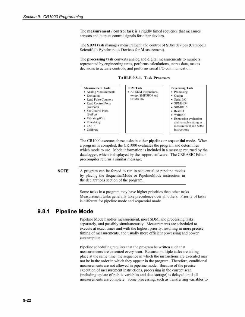
Section 9. CR1000 Programming
9-22
The measurement / control task is a rigidly timed sequence that measures sensors and outputs control signals for other devices.
The SDM task manages measurement and control of SDM devices (Campbell Scientific’s Synchronous Devices for Measurement).
The processing task converts analog and digital measurements to numbers represented by engineering units, performs calculations, stores data, makes decisions to actuate controls, and performs serial I/O communication.
TABLE 9.8-1. Task Processes
Measurement Task • Analog Measurements • Excitation • Read Pulse Counters • Read Control Ports
(GetPort) • Set Control Ports
(SetPort • VibratingWire • PeriodAvg • CS616 • Calibrate
SDM Task • All SDM instructions,
except SMDSIO4 and SDMIO16
Processing Task • Processing • Output • Serial I/O • SDMSIO4 • SDMIO16 • ReadIO • WriteIO • Expression evaluation
and variable setting in measurement and SDM instructions
The CR1000 executes these tasks in either pipeline or sequential mode. When a program is compiled, the CR1000 evaluates the program and determines which mode to use. Mode information is included in a message returned by the datalogger, which is displayed by the support software. The CRBASIC Editor precompiler returns a similar message.
A program can be forced to run in sequential or pipeline modes by placing the SequentialMode or PipelineMode instruction in the declarations section of the program.
Some tasks in a program may have higher priorities than other tasks. Measurement tasks generally take precedence over all others. Priority of tasks is different for pipeline mode and sequential mode.
9.8.1 Pipeline Mode Pipeline Mode handles measurement, most SDM, and processing tasks separately, and possibly simultaneously. Measurements are scheduled to execute at exact times and with the highest priority, resulting in more precise timing of measurements, and usually more efficient processing and power consumption.
Pipeline scheduling requires that the program be written such that measurements are executed every scan. Because multiple tasks are taking place at the same time, the sequence in which the instructions are executed may not be in the order in which they appear in the program. Therefore, conditional measurements are not allowed in pipeline mode. Because of the precise execution of measurement instructions, processing in the current scan (including update of public variables and data storage) is delayed until all measurements are complete. Some processing, such as transferring variables to
NOTE

Section 9. CR1000 Programming
9-23
control instructions, such as PortSet () and ExciteV (), may not be completed until the next scan.
When a condition is true for a task to start, it is put in a queue. Because all tasks are given the same priority, the task is put at the back of the queue. Every 10 msec (or faster if a new task is triggered) the task currently running is paused and put at the back of the queue, and the next task in the queue begins running. In this way, all tasks are given equal processing time by the datalogger.
All tasks are given the same general priority. However, when a conflict arises between tasks, program execution adheres to the priority schedule in TABLE 9.8-2.
TABLE 9.8-2. Pipeline Mode Task Priorities
1) Measurements in main program
2) Background calibration
3) Measurements in slow sequences
4) Processing tasks
9.8.2 Sequential Mode Sequential mode executes instructions in the sequence in which they are written in the program. Sequential mode may be slower than pipeline mode since it executes only one line of code at a time. After a measurement is made, the result is converted to a value determined by processing included in the measurement instruction, and then execution proceeds to the next instruction. This line-by-line execution allows writing conditional measurements into the program.
The exact time at which measurements are made in sequential mode may vary if other measurements or processing are made conditionally, if there is heavy communications activity, or if other interrupts such as inserting a CF card occur.
When running in sequential mode, the datalogger uses a queuing system for processing tasks similar to the one used in pipeline mode. The main difference when running a program in sequential mode is that there is no prescheduled timing of measurements; instead, all instructions are executed in their programmed order.
A priority scheme is used to avoid conflicting use of measurement hardware. The main scan has the highest priority and prevents other sequences from using measurement hardware until the main scan, including processing, is complete. Other tasks, such as processing from other sequences and communications, can occur while the main sequence is running. Once the main scan has finished, other sequences have access to measurement hardware with the order of priority being the background calibration sequence followed by the slow sequences in the order they are declared in the program.
NOTE

Section 9. CR1000 Programming
9-24
Measurement tasks have priority over other tasks such as processing and communication to allow accurate timing needed within most measurement instructions.
9.9 Program Execution Timing Timing instructions facilitate continuous, precisely timed looping of program segments. Executable code begins with “BeginProg” and ends with “EndProg.” Sequence and timing of measurements, processing, and calls to data tables within executable code are determined by one or more timing instructions listed in Table 9.9-1.
Table 9.9-1 Program Timing Instructions
Instructions General Guidelines Syntax Form Scan () / NextScan Use in most programs. The “main
scan.”
BeginProg Scan () . . . NextScan EndProg
SlowSequence / EndSequence Use when measurements or processing must run at slower frequencies from that of the main program.
BeginProg Scan () . . . NextScan SlowSequence Scan () . . . NextScan EndSequence EndProg
SubScan / NextSubScan Use when measurements or processing must run at faster frequencies from that of the main program.
BeginProg Scan () . . . SubScan() . . . NextSubScan NextScan EndProg
NOTE

Section 9. CR1000 Programming
9-25
9.9.1 Scan () / NextScan Simple CR1000 programs are often built entirely within a single Scan () / NextScan structure, with only variable and data table declarations outside the Scan () / NextScan structure. In these simple programs, Scan () / NextScan creates an infinite loop, each periodic pass through the loop being synchronized to the CR1000 clock. Scan () parameters allow modification of the period. As shown in EXAMPLE 9.9-1, aside from declarations, the CRBASIC program may be relatively short.
EXAMPLE 9.9-1. CRBASIC Code: BeginProg / Scan / NextScan / EndProg Syntax
BeginProg Scan (1,Sec,3,0) PanelTemp (RefTemp, 250) TCDiff (TC(),6,mV2_5C,1,TypeT,RefTemp,RevDiff,Del,Integ,Mult,Offset) CallTable Temp NextScan EndProg
Scan () determines how frequently instructions in the program are executed:
EXAMPLE 9.9-2. CRBASIC Code: Scan Syntax
'Scan (Interval, Units, BufferSize, Count) Scan (1,Sec,3,0) · · · ExitScan
Scan has four parameters:
Interval is the interval between scans.
Units is the time unit for the interval. Interval is 10 ms < = Interval < = 1 day.
BufferSize is the size (number of scans) of a buffer in RAM that holds the raw results of measurements. When running in Pipline mode, using a buffer allows the processing in the scan to lag behind measurements at times without affecting measurement timing. Use of the CRBASIC Editor default size is normal. Refer to Section 19.1.1.2 for troubleshooting tips.
Count is number of scans to make before proceeding to the instruction following NextScan. A count of 0 means to continue looping forever (or until ExitScan). In the example in EXAMPLE 9.9-2, the scan is 1 second, three scans are buffered, and measurements and data storage continue indefinitely.

Section 9. CR1000 Programming
9-26
9.9.2 SlowSequence / EndSequence Instructions in a slow sequence scan are executed whenever the main scan is not active. When running in pipeline mode, slow sequence measurements is spliced in after measurements in the main program, as time allows. Because of this splicing, the measurements in a slow sequence may actually span across multiple main program scan intervals. When no measurements need to be spliced, the scan will run independent of the fast scan, so slow sequences with no measurements can run at intervals ≤ main scan interval (still in 100 ms increments) without skipping scans. When splicing, checking for skipped slow scans is done after the first splice is complete rather than immediately after the interval comes true.
In sequential mode, all instructions in slow sequences are executed as they occur in the program according to task priority. See Section 9.10.2.1 for more information.
Slow sequence scans are declared with the SlowSequence instruction and run outside the main program scan. They typically run at a slower rate than the main scan. Up to four slow sequences scans can be defined in a program.
Background calibration is an automatic slow sequence scan.
Read More! Section 4.2.8 Self-Calibration.
9.9.3 SubScan () / NextSubScan SubScan () / NextSubScan are used in the control of analog multiplexers (see Appendix F.5 for information on available analog multiplexers) or to measure analog inputs at a faster rate than the program scan. SubScans cannot be nested or placed in a SlowSequence. PulseCount or SDM measurement cannot be used within a sub scan.
9.9.4 Scan Priorities in Sequential Mode Measurement tasks have priority over other tasks such as processing and communication to allow accurate timing needed within most measurement instructions.
A priority scheme is used in sequential mode to avoid conflicting use of measurement hardware. As illustrated in FIGURE 9.9-1, the main scan sequence has the highest priority. Other sequences, such as slow sequences and calibration scans, must wait to access measurement hardware until the main scan, including measurements and processing, is complete.
NOTE

Section 9. CR1000 Programming
9-27
FIGURE 9.9-1. Sequential Mode Scan Priority Flow Diagrams
9.9.4.1 Main Scans Execution of the main scan usually occurs quickly, so the processor may be idle much of the time. For example, a weather measurement program may scan once per second, but program execution may only occupy 250 ms, leaving 75% of available scan time unused. The CR1000 can make efficient use of this interstitial scan time to optimize program execution and communications control. Unless disabled, or crowded out by a too demanding schedule, self-calibration (see Section 4.2.8) has priority and uses some interstitial scan time1. Remaining priorities include slow sequence scans in the order they are programmed and digital triggers. Following is a brief introduction to the rules and priorities that govern use of interstitial scan time in sequential mode. Rules and priorities governing pipeline mode are somewhat more complex and are not expanded upon here.
Permission to proceed with a measurement is granted by the measurement semaphore. Main scans with measurements have priority to acquire the semaphore before measurements in a calibration or slow sequence scan. The semaphore is taken by the main scan at its beginning if there are measurements

Section 9. CR1000 Programming
9-28
included in the scan. The semaphore is released only after the last instruction in the main scan is executed.
9.9.4.2 Slow Sequence Scans Slow sequence scans begin after a SlowSequence instruction. Slow sequence scans start processing tasks prior to a measurement but stop to wait when a measurement semaphore is needed. Slow sequences release the semaphore after complete execution of each measurement instruction to allow the main scan to acquire the semaphore when it needs to start. If the measurement semaphore is set by a slow sequence scan and the beginning of a main scan gets to the top of the queue, the main scan will not start until it can get the semaphore; it waits for the slow sequence to release the semaphore. A slow sequence scan does not hold the semaphore for the whole of its scan. It releases the semaphore after each use of the hardware.
9.9.4.3 WaitDigTrig Scans Main scans and slow sequences usually trigger at intervals defined by the Scan () instruction. Some applications, however, require the main or slow sequence scan to be started by an external digital trigger, i.e. a 5V pulse on a control port. The WaitDigTrig () instruction activates a program when an extermal trigger is detected. WaitDigTrig() gives priority to begin a scan, but the scan will execute and acquire the semaphore according to the rules stated in Sections 9.9.4.1 and 9.9.4.2. Any processing will be time sliced with processing from other sequences. Every time the program encounters WaitDigTrig (), it will stop and wait to be triggered
Programming Tip: This is how one CR1000 can control the scan time of another CR1000.
1If self-calibration is crowded out, a warning message indicating as much is issued by the CRBASIC compiler.
9.10 Instructions In addition to BASIC syntax, additional instructions are included in CRBASIC to facilitate measurements and store data. Section 10 contains a comprehensive list of these instructions.
9.10.1 Measurement and Data Storage Processing CRBASIC instructions have been created for making measurements and storing data. Measurement instructions set up CR1000 hardware to make measurements and store results in variables. Data storage instructions process measurements into averages, maxima, minima, standard deviation, FFT, etc.
Each instruction is a keyword followed by a series of informational parameters needed to complete the procedure. For example, the instruction for measuring CR1000 panel temperature is:
PanelTemp (Dest, Integ)
“PanelTemp” is the keyword. Two parameters follow: Dest, a destination variable name in which the temperature value is stored; and Integ, a length of time to integrate the measurement. To place the panel temperature
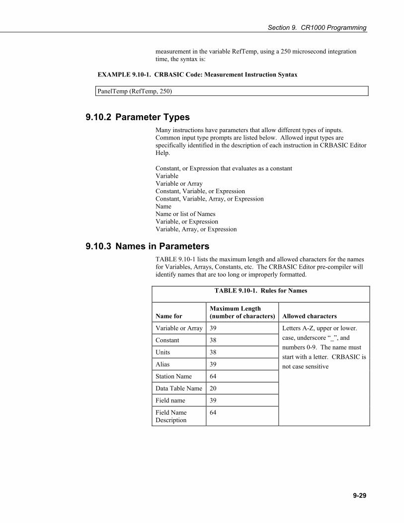
Section 9. CR1000 Programming
9-29
measurement in the variable RefTemp, using a 250 microsecond integration time, the syntax is:
EXAMPLE 9.10-1. CRBASIC Code: Measurement Instruction Syntax
PanelTemp (RefTemp, 250)
9.10.2 Parameter Types Many instructions have parameters that allow different types of inputs. Common input type prompts are listed below. Allowed input types are specifically identified in the description of each instruction in CRBASIC Editor Help.
Constant, or Expression that evaluates as a constant Variable Variable or Array Constant, Variable, or Expression Constant, Variable, Array, or Expression Name Name or list of Names Variable, or Expression Variable, Array, or Expression
9.10.3 Names in Parameters TABLE 9.10-1 lists the maximum length and allowed characters for the names for Variables, Arrays, Constants, etc. The CRBASIC Editor pre-compiler will identify names that are too long or improperly formatted.
TABLE 9.10-1. Rules for Names
Name for
Maximum Length (number of characters)
Allowed characters
Variable or Array 39
Constant 38
Units 38
Alias 39
Station Name 64
Data Table Name 20
Field name 39
Field Name Description
64
Letters A-Z, upper or lower. case, underscore “_”, and numbers 0-9. The name must start with a letter. CRBASIC is not case sensitive

Section 9. CR1000 Programming
9-30
9.10.4 Expressions in Parameters Read More! See Section 9.11 for more information on expressions.
Many parameters allow the entry of expressions. If an expression is a comparison, it will return -1 if the comparison is true and 0 if it is false (Section 9.11.4 Logical Expressions). EXAMPLE 9.10-2 shows an example of the use of expressions in parameters in the DataTable instruction, where the trigger condition is entered as an expression. Suppose the variable TC is a thermocouple temperature:
EXAMPLE 9.10-2. CRBASIC Code: Use of Expressions in Parameters
‘DataTable (Name, TrigVar, Size) DataTable (Temp, TC > 100, 5000)
When the trigger is “TC > 100”, a TC temperature > 100 will set the trigger to true and data is stored.
9.10.5 Arrays of Multipliers and Offsets A single measurement instruction can measure a series of sensors and apply individual calibration factors to each sensor as shown in EXAMPLE 9.10-3. Storing calibration factors in variable arrays, and placing the array variables in the multiplier and offset parameters of the measurement instruction, makes this possible. The measurement instruction uses repetitions to implement this feature by stepping through the multiplier and offset arrays as it steps through the measurement input channels. If the multiplier and offset are not arrays, the same multiplier and offset are used for each repetition.
EXAMPLE 9.10-3. CRBASIC Code: Use of Arrays as Multipliers and Offsets
Public Pressure(3), Mult(3), Offset(3) DataTable (AvgPress,1,-1) DataInterval (0,60,Min,10) Average (3,Pressure(),IEEE4,0) EndTable BeginProg 'Calibration Factors: Mult(1)=0.123 : Offset(1)=0.23 Mult(2)=0.115 : Offset(2)=0.234 Mult(3)=0.114 : Offset(3)=0.224 Scan (1,Sec,10,0) 'VoltSe instruction using array of multipliers and offsets: VoltSe (Pressure(),3,mV5000,1,True,0,_60Hz,Mult(),Offset()) CallTable AvgPress NextScan EndProg
Read More! More information is available in CRBASIC Editor Help topic “Multipliers and Offsets with Repetitions”.
Section 9. CR1000 Programming
9-31
9.11 Expressions An expression is a series of words, operators, or numbers that produce a value or result. Expressions are evaluated from left to right, with deference to precedence rules. The result of each stage of the evaluation is of type Long (integer) if the variables are of type Long (constants are integers) and the functions give integer results, such as occurs with INTDV (). If part of the equation has a floating point variable or constant, or a function that results in a floating point, the rest of the expression is evaluated using floating point math, even if the final function is to convert the result to an integer; e.g. INT ((rtYear-1993)*.25). This is a critical feature to consider when 1) trying to use Long integer math to retain numerical resolution beyond the limit of floating point variables (24 bits), or 2) if the result is to be tested for equivalence against another value (see Section 9.13.1 for limits of floating point precision).
Two types of expressions, mathematical and programming, are used in CRBASIC. A useful property of expressions in CRBASIC is that they are equivalent to and often interchangeable with their results.
Consider the expressions:
x = (z * 1.8) + 32 (a mathematical expression) If x = 23 then y = 5 (programming expression)
The variable x can be omitted and the expressions combined and written as:
If (z * 1.8 + 32 = 23) then y = 5
Replacing the result with the expression should be done judiciously and with the realization that doing so may make program code more difficult to decipher.
9.11.1 Floating Point Arithmetic Variables and calculations are performed internally in single precision IEEE4 byte floating point with some operations calculated in double precision.
Single precision float has 24 bits of mantissa. Double precision has a 32-bit extension of the mantissa, resulting in 56 bits of precision. Instructions that use double precision are AddPrecise, Average, AvgRun, AvgSpa, CovSpa, MovePrecise, RMSSpa, StdDev, StdDevSpa, and Totalize.
Floating point arithmetic is common in many electronic computational systems, but it has pitfalls high-level programmers should be aware of. Several sources discuss floating point arithmetic thoroughly. One readily available source is the topic “Floating Point” at Wikipedia.org. In summary, CR1000 programmers should consider at least the following:
• Floating point numbers do not perfectly mimic real numbers.
• Floating point arithmetic does not perfectly mimic true arithmetic.
NOTE

Section 9. CR1000 Programming
9-32
• Avoid use of equality in conditional statements. Use >= and <= instead. For example, use “If X => Y, then do” rather than using, “If X = Y, then do”.
• When programming extended cyclical summation of non-integers, use the AddPrecise() instruction. Otherwise, as the size of the sum increases, fractional addends will have ever decreasing effect on the magnitude of the sum, because normal floating point numbers are limited to about 7 digits of resolution.
9.11.2 Mathematical Operations Mathematical operations are written out much as they are algebraically. For example, to convert Celsius temperature to Fahrenheit, the syntax is:
TempF = TempC * 1.8 + 32
EXAMPLE 9.11-1 shows example code to convert twenty temperatures in a variable array from C to F:
EXAMPLE 9.11-1. CRBASIC Code: Use of variable arrays to save code space.
For I = 1 to 20 TCTemp(I) = TCTemp(I) * 1.8 + 32 Next I
9.11.3 Expressions with Numeric Data Types FLOATs, LONGs and Booleans are cross-converted to other data types, such as FP2, by using “=”
9.11.3.1 Boolean from FLOAT or LONG When a FLOAT or LONG is converted to a Boolean as shown in EXAMPLE 9.11-2, zero becomes False (0) and non-zero becomes True (-1).
EXAMPLE 9.11-2. CRBASIC Code: Conversion of FLOAT / LONG to Boolean
Public Fa AS FLOAT Public Fb AS FLOAT Public L AS LONG Public Ba AS Boolean Public Bb AS Boolean Public Bc AS Boolean BeginProg Fa = 0 Fb = 0.125 L = 126 Ba = Fa ‘This will set Ba = False (0) Bb = Fb ‘This will Set Bb = True (-1) Bc = L ‘This will Set Bc = True (-1) EndProg

Section 9. CR1000 Programming
9-33
9.11.3.2 FLOAT from LONG or Boolean When a LONG or Boolean is converted to FLOAT, the integer value is loaded into the FLOAT. Booleans are converted to -1 or 0 depending on whether the value is non-zero or zero. LONG integers greater than 24 bits (16,777,215; the size of the mantissa for a FLOAT) will lose resolution when converted to FLOAT.
9.11.3.3 LONG from FLOAT or Boolean Boolean is converted to -1 or 0. When a FLOAT is converted to a LONG, it is truncated. This conversion is the same as the INT function (Section 10.6.4 Arithmetic Functions). The conversion is to an integer equal to or less than the value of the float (e.g., 4.6 becomes 4, -4.6 becomes -5).
If a FLOAT is greater than the largest allowable LONG (+2,147,483,647), the integer is set to the maximum. If a FLOAT is less than the smallest allowable LONG (-2,147,483,648), the integer is set to the minimum.
9.11.3.4 Integers in Expressions LONGs are evaluated in expressions as integers when possible. EXAMPLE 9.11-3 illustrates evaluation of integers as LONGs and FLOATs.
EXAMPLE 9.11-3. CRBASIC Code: Evaluation of Integers
Public X, I AS Long BeginProg I = 126 X = (I+3) * 3.4 ‘I+3 is evaluated as an integer, ‘then converted to FLOAT before ‘it is multiplied by 3.4 EndProg
9.11.3.5 Constants Conversion Constants are not declared with a data type, so the CR1000 assigns the data type as needed. If a constant (either entered as a number or declared with CONST) can be expressed correctly as an integer, the compiler will use the type that is most efficient in each expression. The integer version is used if possible, i.e., if the expression has not yet encountered a float. EXAMPLE 9.11-4 lists a programming case wherein a value normally considered an integer (10) is assigned by the CR1000 to be As Float.

Section 9. CR1000 Programming
9-34
EXAMPLE 9.11-4. CRBASIC Code: Constants to LONGs or FLOATs
Public I AS Long Public A1, A2 CONST ID = 10 BeginProg A1 = A2 + ID I = ID * 5 EndProg
In EXAMPLE 9.11-4, I is an integer. A1 and A2 are Floats. The number 5 is loaded As Float to add efficiently with constant ID, which was compiled As Float for the previous expression to avoid an inefficient run time conversion from integer to float before each floating point addition.
9.11.4 Logical Expressions Measurements made by the CR1000 can indicate the absence or presence of certain conditions. For example, an RH measurement of 100% indicates a condensation event such as fog, rain, or dew. CR1000’s can render events into a binary form for further processing, i.e., events can either be TRUE1 (equal to -1 in the CR1000)2, indicating the condition occurred or is occurring, or FALSE (0), indicating the condition has not yet occurred or is over.
The CR1000 is able to translate the conditions listed in TABLE 9.11-1 to binary form (-1 or 0), using the listed instructions and saving the binary form in the memory location indicated.
1 Several words are commonly interchanged with True / False such as High / Low, On / Off, Yes / No, Set / Reset, Trigger / Do Not Trigger. The CR1000 understands only True / False or -1 / 0, however. The CR1000 represents “true” with “-1” because AND / OR operators are the same for logical statements and binary bitwise comparisons.
2 In the binary number system internal to the CR1000, “-1” is expressed with all bits equal to 1 (11111111). “0” has all bits equal to 0 (00000000). When -1 is ANDed with any other number, the result is the other number. This ensures that if the other number is non-zero (true), the result is non-zero.

Section 9. CR1000 Programming
9-35
TABLE 9.11-1. Binary Conditions of TRUE and FALSE
Condition CRBASIC
Instruction(s) Used Memory Location of
Binary Result
Time TimeIntoInterval () Variable, System IfTime () Variable, System
Control Port Trigger WaitDigTrig () System
Communications VoiceBeg () System ComPortIsActive () Variable PPPClose () Variable
Measurement Event DataEvent () System
Using TRUE or FALSE conditions with logic operators such as AND and OR, logical expressions can be encoded into a CR1000 to perform three general logic functions, facilitating conditional processing and control applications.
1. Evaluate an expression, take one path or action if the expression is true (= -1), and / or another path or action if the expression is false (= 0).
2. Evaluate multiple expressions linked with AND or OR.
3. Evaluate multiple and / or links.
The following commands and logical operators are used to construct logical expressions. EXAMPLE 9.11-5 a - f demonstrate some logical expressions.
IF AND OR NOT XOR IMP IIF
EXAMPLE 9.11-5. Logical Expression Examples
a. If X >= 5 then Y = 0 Sets the variable Y to 0 if the expression “X >= 5” is true, i.e. if X is greater than or equal to 5. The CR1000 evaluates the expression (X >= 5) and registers in system memory a -1 if the expression is true, or a 0 if the expression is false.

Section 9. CR1000 Programming
9-36
b. If X >= 5 AND Z = 2 then Y = 0 Sets Y = 0 only if both X >= 5 and Z = 2 are true.
c. If X >= 5 OR Z = 2 then Y = 0
Sets Y = 0 if either X >= 5 or Z = 2 is true.
d. If 6 then Y = 0.
“If 6” is true since “6” (a non-zero number) is returned, so Y is set to 0 every time the statement is executed. Likewise, consider the equally impractical statement
e. If 0 then Y = 0.
“If 0” is false since “0” is returned, so Y will never be set to 0 by this statement.
f. Z = (X > Y).
Z will equal -1 if X > Y, or Z will equal 0 if X <= Y.
g. The NOT operator simply complements every bit in the word. A Boolean
can only be 0 or have all of its bits set to 1. Complementing a Boolean will turn TRUE (all bits set) to FALSE (all bits complemented to 0).
Example: (a AND b) = (26 AND 26) = (&b11010 AND &b11010) = &b11010. NOT (&b11010) yields &b00101. This is non-zero, so when converted to a BOOLEAN, it becomes TRUE. Public a AS Long Public b AS Long Public is_true AS Boolean Public not_is_true AS Boolean Public not_a_and_b AS Boolean BeginProg a = 26 b = a Scan (1,Sec,0,0) is_true = a AND b 'This evaluates to TRUE. not_is_true = NOT (is_true) 'This evaluates to FALSE. not_a_and_b = NOT (a AND b) 'This evaluates to TRUE! NextScan EndProg
9.11.5 String Expressions CRBASIC allows the addition or concatenation of string variables to variables of all types using & and + operators. To ensure consistent results, use “&” when concatenating strings. Use “+” when concatenating strings to other variable types. EXAMPLE 9.11-6 demonstrates CRBASIC code for concatenating strings and integers.

Section 9. CR1000 Programming
9-37
EXAMPLE 9.11-6. CRBASIC Code: String and Variable Concatenation
'Declare Variables Dim Wrd(8) As String * 10 Public Phrase(2) As String * 80 Public PhraseNum(2) As Long 'Declare Data Table DataTable (Test,1,-1) DataInterval (0,15,Sec,10) 'Write phrases to data table "Test" Sample (2,Phrase,String) EndTable 'Program BeginProg Scan (1,Sec,0,0) 'Assign strings to String variables Wrd(1) = " ":Wrd(2) = "Good":Wrd(3) = "morning":Wrd(4) = "Don't" Wrd(5) = "do":Wrd(6) = "that":Wrd(7) = ",":Wrd(8) = "Dave" 'Assign integers to Long variables PhraseNum(1) = 1:PhraseNum(2) = 2 'Concatenate string "1 Good morning, Dave" Phrase(1) = PhraseNum(1)+Wrd(1)&Wrd(2)&Wrd(1)&Wrd(3)&Wrd(7)&Wrd(1)&Wrd(8) 'Concatenate string "2 Don't do that, Dave" Phrase(2) = PhraseNum(2)+Wrd(1)&Wrd(4)&Wrd(1)&Wrd(5)&Wrd(1)&Wrd(6)&Wrd(7)&Wrd(1)&Wrd(8) CallTable Test NextScan EndProg
9.12 Program Access to Data Tables CRBASIC has syntax provisions facilitating access to data in tables or information relating to a table. Except when using the GetRecord () instruction (Section 10.15 Data Table Access and Management), the syntax is entered directly into the CRBASIC program through a variable name. The general form is:
“TableName.FieldName_Prc (Fieldname Index, Records Back)”.
Where:
TableName = name of the data table
FieldName = name of the variable from which the processed value is derived
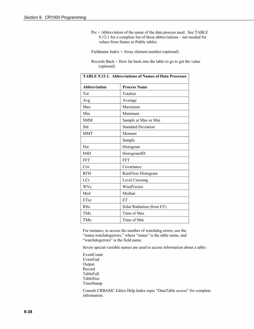
Section 9. CR1000 Programming
9-38
Prc = Abbreviation of the name of the data process used. See TABLE 9.12-1 for a complete list of these abbreviations – not needed for values from Status or Public tables.
Fieldname Index = Array element number (optional)
Records Back = How far back into the table to go to get the value (optional)
TABLE 9.12-1. Abbreviations of Names of Data Processes
Abbreviation Process Name Tot Totalize Avg Average Max Maximum Min Minimum SMM Sample at Max or Min Std Standard Deviation MMT Moment Sample Hst Histogram H4D Histogram4D FFT FFT Cov Covariance RFH RainFlow Histogram LCr Level Crossing WVc WindVector Med Median ETsz ET RSo Solar Radiation (from ET) TMx Time of Max TMn Time of Min For instance, to access the number of watchdog errors, use the “status.watchdogerrors,” where “status” is the table name, and “watchdogerrors” is the field name.
Seven special variable names are used to access information about a table:
EventCount EventEnd Output Record TableFull TableSize TimeStamp
Consult CRBASIC Editor Help Index topic “DataTable access” for complete information.

10-1
Section 10. CRBASIC Programming Instructions
Read More! Parameter listings, application information, and code examples are available in CRBASIC Editor Help. CRBASIC Editor is part of LoggerNet / PC400 / RTDAQ.
Select instructions are explained more fully, some with example code, in Section 11 Programming Resource Library. Example code is throughout the CR1000 manual. Refer to the table of contents Example index.
10.1 Program Declarations AngleDegrees Sets math functions to use degrees instead of radians.
Syntax AngleDegrees
PipelineMode Configures datalogger to perform measurement tasks separate from, but concurrent with, processing tasks.
Syntax PipelineMode
SetSecurity Sets numeric password for datalogger security levels 1, 2, and 3. Security[I] are constants. Executes at compile time.
Syntax SetSecurity (security[1], security[2], security[3])
SequentialMode Configures datalogger to perform tasks sequentially.
Syntax SequentialMode
StationName Sets the station name internal to the CR1000. Does not affect data files produced by support software.
Syntax StationName (name of station)
Sub, ExitSub, EndSub Declares the name, variables, and code that form a Subroutine. Argument list is optional. Exit Sub is optional.
Syntax Sub subname (argument list) [ statement block ] Exit Sub [ statement block ] End Sub

Section 10. CRBASIC Programming Instructions
10-2
WebPageBegin / WebPageEnd See Section 11.2 Information Services.
10.1.1 Variable Declarations & Modifiers Alias Assigns a second name to a variable.
Syntax Alias [variable] = [alias name]
As Sets data type for DIM or PUBLIC variables.
Syntax Dim [variable] AS [data type]
Dim Declares and dimensions private variables. Dimensions are optional.
Syntax Dim [variable name (x,y,z)]
ESSVariables Automatically declares all the variables required for the datalogger when used in an Environmental Sensor Station application. Used in conjunction with ESSInitialize.
Syntax ESSVariables
NewFieldNames Assigns a new name to a generic variable or array. Designed for use with CSI wireless sensor networks.
Syntax NewFieldNames (GenericName, NewNames)
PreserveVariables Retains values in Dim or Public variables when program restarts after a power failure or manual stop.
Syntax PreserveVariables
Public Declares and dimensions public variables. Dimensions are optional.
Syntax Public [variable name (x,y,z)]
Units Assigns a unit name to a field associated with a variable.
Syntax Units [variable] = [unit name]
10.1.2 Constant Declarations Const Declares symbolic constants for use in place of numeric entries.
Syntax Const [constant name] = [value or expression]

Section 10. CRBASIC Programming Instructions
10-3
ConstTable … EndConstTable Declares constants, the value of which can be changed using the datalogger keyboard or terminal ‘C’ option. The program is recompiled with the new values when values change.
Syntax ConstTable [constant a] = [value] [constant b] = [value] [constant c] = [value] EndConstTable
10.2 Data Table Declarations DataTable … EndTable Mark the beginning and end of a data table.
Syntax DataTable (Name, TrigVar, Size) [data table modifiers] [on-line storage destinations] [output processing instructions] EndTable
10.2.1 Data Table Modifiers DataEvent Sets triggers to start and stop storing records within a table. One application is with WorstCase.
Syntax DataEvent (RecsBefore, StartTrig, StopTrig, RecsAfter)
DataInterval Sets the time interval for an output table.
Syntax DataInterval (TintoInt, Interval, Units, Lapses)
FillStop Sets a data table to fill and stop.
Syntax FillStop
To reset a table after it fills and stops, use ResetTable () instruction in the user program or LoggerNet / PC400 / RTDAQ / PC200W | Datalogger | Station Status | Table Fill Times | Reset Tables.
OpenInterval Sets time series processing to include all measurements since the last time data storage occurred.
Syntax OpenInterval
NOTE

Section 10. CRBASIC Programming Instructions
10-4
10.2.2 Data Destinations CardOut Send output data to a CF card module.
Syntax CardOut (StopRing, Size)
DSP4 Send data to the DSP4 display
Syntax DSP4 (FlagVar, Rate)
TableFile Writes a file from a data table to the datalogger CPU, user drive, or a compact flash card.
Syntax TableFile ("FileName", Options, MaxFiles, NumRecs / TimeIntoInterval, Interval, Units, OutStat, LastFileName)
10.2.3 Data Storage Output Processing FieldNames Immediately follows an output processing instruction to change default field names.
Syntax FieldNames ("Fieldname1 : Description1, Fieldname2 : Description2…")
10.2.3.1 Single-Source Average Stores the average value over the output interval for the source variable or each element of the array specified.
Syntax Average (Reps, Source, DataType, DisableVar)
Covariance Calculates the covariance of values in an array over time.
Syntax Covariance (NumVals, Source, DataType, DisableVar, NumCov)
FFT Performs a Fast Fourier Transform on a time series of measurements stored in an array.
Syntax FFT (Source, DataType, N, Tau, Units, Option)
Maximum Stores the maximum value over the output interval.
Syntax Maximum (Reps, Source, DataType, DisableVar, Time)
Median Stores the median of a dependant variable over the output interval
Syntax Median (Reps, Source, MaxN, DataType, DisableVar)

Section 10. CRBASIC Programming Instructions
10-5
Minimum Stores the minimum value over the output interval.
Syntax Minimum (Reps, Source, DataType, DisableVar, Time)
Moment Stores the mathematical moment of a value over the output interval.
Sytnax Moment (Reps, Source, Order, DataType, DisableVar)
PeakValley Detects maxima and minima in a signal.
Syntax PeakValley (DestPV, DestChange, Reps, Source, Hysteresis)
Sample Stores the current value at the time of output.
Syntax Sample (Reps, Source, DataType)
SampleFieldCal Writes field calibration data to a table. See Section 6.19 Calibration Functions.
SampleMaxMin Samples a variable when another variable reaches its maximum or minimum for the defined output period.
Syntax SampleMaxMin (Reps, Source, DataType, DisableVar)
StdDev Calculates the standard deviation over the output interval.
Syntax StdDev (Reps, Source, DataType, DisableVar)
Totalize Sums the total over the output interval.
Syntax Totalize (Reps, Source, DataType, DisableVar)
10.2.3.2 Multiple-Source ETsz Stores evapotranspiration (ETsz) and solar radiation (RSo).
Syntax ETsz (Temp, RH, uZ, Rs, Longitude, Latitude, Altitude, Zw, Sz, DataType, DisableVar)
WindVector Read More! See Section 11.5 Wind Vector.
Processes wind speed and direction from either polar or orthogonal sensors. To save processing time, only calculations resulting in the requested data are performed.

Section 10. CRBASIC Programming Instructions
10-6
Syntax WindVector (Repetitions, Speed/East, Direction/North, DataType, DisableVar, Subinterval, SensorType, OutputOpt)
10.2.4 Histograms Histogram Processes input data as either a standard histogram (frequency distribution) or a weighted value histogram.
Syntax Histogram (BinSelect, DataType, DisableVar, Bins, Form, WtVal, LoLim, UpLim)
Histogram4D Processes input data as either a standard histogram (frequency distribution) or a weighted value histogram of up to 4 dimensions.
Syntax Histogram4D (BinSelect, Source, DataType, DisableVar, Bins1, Bins2, Bins3, Bins4, Form, WtVal, LoLim1, UpLim1, LoLim2, UpLim2, LoLim3, UpLim3, LoLim4, UpLim4)
LevelCrossing Processes data into a one or two dimensional histogram using a level crossing counting algorithm.
Syntax LevelCrossing (Source, DataType, DisableVar, NumLevels, 2ndDim, CrossingArray, 2ndArray, Hysteresis, Option)
RainFlow Creates a rainflow histogram.
Syntax RainFlow (Source, DataType, DisableVar, MeanBins, AmpBins, Lowlimit, Highlimit, MinAmp, Form)
10.3 Single Execution at Compile Reside between BeginProg and Scan Instructions.
ESSInitialize Placed after the BeginProg instruction but prior to the Scan instruction to initialize ESS variables at compile time.
Syntax ESSInitialize
MovePrecise Used in conjunction with AddPrecise, moves a high precision variable into another input location.
Syntax MovePrecise (PrecisionVariable, X)
PulseCountReset Resets the pulse counters and the running averages used in the pulse count instruction.
Syntax PulseCountReset

Section 10. CRBASIC Programming Instructions
10-7
10.4 Program Control Instructions 10.4.1 Common Controls
BeginProg … EndProg Mark the beginning and end of a program.
Syntax BeginProg Program Code EndProg
Call Transfers program control from the main program to a subroutine.
Syntax Call subname (list of variables)
CallTable Calls a data table, typically for output processing.
Syntax CallTable [TableName]
Delay Delays the program.
Syntax Delay (Option, Delay, Units)
Do … Loop Repeats a block of statements while a condition is true or until a condition becomes true.
Syntax Do [While | Until condition] [statementblock] [ExitDo] [statementblock] Loop -or- Do [statementblock] [ExitDo] [statementblock] Loop [While | Until condition]
EndSequence Ends the current sequence that started at Begin Prog or after a SlowSequence and accompanying declaration sequences.
Syntax EndSequence
Exit Exit program.
Syntax Exit
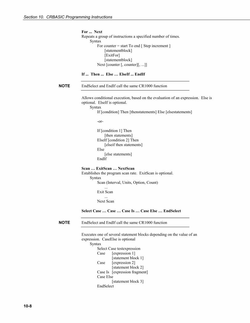
Section 10. CRBASIC Programming Instructions
10-8
For ... Next Repeats a group of instructions a specified number of times.
Syntax For counter = start To end [ Step increment ] [statementblock] [ExitFor] [statementblock] Next [counter [, counter][, ...]]
If ... Then ... Else … ElseIf ... EndIf
EndSelect and EndIf call the same CR1000 function
Allows conditional execution, based on the evaluation of an expression. Else is optional. ElseIf is optional.
Syntax If [condition] Then [thenstatements] Else [elsestatements] -or- If [condition 1] Then [then statements] ElseIf [condition 2] Then [elseif then statements] Else [else statements] EndIf
Scan … ExitScan … NextScan Establishes the program scan rate. ExitScan is optional.
Syntax Scan (Interval, Units, Option, Count) ... Exit Scan ... Next Scan
Select Case … Case … Case Is … Case Else … EndSelect
EndSelect and EndIf call the same CR1000 function
Executes one of several statement blocks depending on the value of an expression. CaseElse is optional
Syntax Select Case testexpression Case [expression 1] [statement block 1] Case [expression 2] [statement block 2] Case Is [expression fragment] Case Else [statement block 3] EndSelect
NOTE
NOTE

Section 10. CRBASIC Programming Instructions
10-9
Slow Sequence Marks the beginning of a section of code that will run concurrently with the main program.
Syntax SlowSequence
SubScan … NextSubScan Controls a multiplexer or measures some analog inputs at a faster rate than the program scan.
Syntax SubScan (SubInterval, Units, Count) Measurements and processing NextSubScan
TriggerSequence Used with WaitTriggerSequence to control the execution of code within a slow sequence.
Syntax TriggerSequence (SequenceNum, Timeout)
WaitTriggerSequence Used with TriggerSequence to control the execution of code within a slow sequence.
Syntax WaitTriggerSequence
WaitDigTrig Triggers a measurement scan from an external digital trigger.
Syntax WaitDigTrig (ControlPort, Option)
While…Wend Execute a series of statements in a loop as long as a given condition is true.
Syntax While Condition [StatementBlock] Wend
10.4.2 Advanced Controls Data … Read … Restore Defines a list of Float constants to be read (using Read) into a variable array later in the program.
Syntax Data [list of constants] Read [VarExpr] Restore

Section 10. CRBASIC Programming Instructions
10-10
DataLong … Read … Restore Defines a list of Long constants to be read (using Read) into a variable array later in the program.
Syntax DataLong [list of constants] Read [VarExpr] Restore
Read Reads constants from the list defined by Data or DataLong into a variable array.
Syntax Read [VarExpr]
Restore Resets the location of the Read pointer back to the first value in the list defined by Data or DataLong.
SemaphoreGet Acquires semaphore 1-3 to avoid resource conflicts.
Syntax SemaphoreGet ()
SemaphoreRelease Releases semaphore previously acquired with SemaphoreGet ().
Syntax SemaphoreRelease ()
ShutDownBegin Begins code to be run in the event of a normal shutdown such as when sending a new program.
Syntax ShutDownBegin
ShutDownEnd Ends code to be run in the event of a normal shutdown such as when sending a new program.
Syntax ShutDownEnd
10.5 Measurement Instructions Read More! For information on recording data from RS-232 and TTL output sensors, see Section 10.11 Serial Input / Output and Section 11.8 Serial I/O.
10.5.1 Diagnostics Battery Battery Measures input voltage.
Syntax Battery (Dest)

Section 10. CRBASIC Programming Instructions
10-11
ComPortIsActive Returns a Boolean value, based on whether or not activity is detected on the specified COM port.
Syntax variable = ComPortIsActive (ComPort)
InstructionTimes Returns the execution time of each instruction in the program.
Syntax InstructionTimes (Dest)
MemoryTest t Performs a test on the datalogger's CPU and Task memory and store the results in a variable.
Syntax MemoryTest (Dest)
PanelTemp This instruction measures the panel temperature in °C.
Syntax PanelTemp (Dest, Integ)
RealTime Derives the year, month, day, hour, minute, second, microsecond, day of week, and day of year from the datalogger clock and stores the results in an array.
Syntax RealTime (Dest)
Signature Returns the signature for program code in a datalogger program.
Syntax variable = Signature
10.5.2 Voltage VoltDiff Measures the voltage difference between H and L inputs of a differential channel
Syntax VoltDiff (Dest, Reps, Range, DiffChan, RevDiff, SettlingTime, Integ, Mult, Offset)
VoltSe Measures the voltage at a single-ended input with respect to ground.
Syntax VoltSe (Dest, Reps, Range, SEChan, MeasOfs, SettlingTime, Integ, Mult, Offset)

Section 10. CRBASIC Programming Instructions
10-12
10.5.3 Thermocouples Read More! See Section 4.4 Thermocouple Measurements.
TCDiff Measures a differential thermocouple.
Syntax TCDiff (Dest, Reps, Range, DiffChan, TCType, TRef, RevDiff, SettlingTime, Integ, Mult, Offset)
TCSe Measures a single-ended thermocouple.
Syntax TCSe (Dest, Reps, Range, SEChan, TCType, TRef, MeasOfs, SettlingTime, Integ, Mult, Offset)
10.5.4 Bridge Measurements Read More! See Section 4.3 Bridge Resistance Measurements.
BrHalf Measures single-ended voltage of a 3 wire half bridge. Delay is optional.
Syntax BrHalf (Dest, Reps, Range, SEChan, Vx/ExChan, MeasPEx, ExmV, RevEx, SettlingTime, Integ, Mult, Offset)
BrHalf3W Measures ratio of Rs / Rf of a 3 wire half bridge.
Syntax BrHalf3W (Dest, Reps, Range, SEChan, Vx/ExChan, MeasPEx, ExmV, RevEx, SettlingTime, Integ, Mult, Offset)
BrHalf4W Measures ratio of Rs / Rf of a 4 wire half bridge.
Syntax BrHalf4W (Dest, Reps, Range1, Range2, DiffChan, Vx/ExChan, MeasPEx, ExmV, RevEx, RevDiff, SettlingTime, Integ, Mult, Offset)
BrFull Measures ratio of Vdiff / Vx of a 4 wire full bridge. Reports 1000 * (Vdiff / Vx).
Syntax BrFull (Dest, Reps, Range, DiffChan, Vx/ExChan, MeasPEx, ExmV, RevEx, RevDiff, SettlingTime, Integ, Mult, Offset)
BrFull6W Measures ratio of Vdiff2 / Vdiff1 of a 6 wire full bridge. Reports 1000 * (Vdiff2 / Vdiff1).
Syntax BrFull6W (Dest, Reps, Range1, Range2, DiffChan, Vx/ExChan, MeasPEx, ExmV, RevEx, RevDiff, SettlingTime, Integ, Mult, Offset)
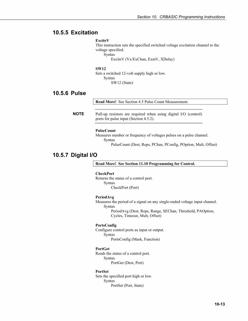
Section 10. CRBASIC Programming Instructions
10-13
10.5.5 Excitation ExciteV This instruction sets the specified switched voltage excitation channel to the voltage specified.
Syntax ExciteV (Vx/ExChan, ExmV, XDelay)
SW12 Sets a switched 12-volt supply high or low.
Syntax SW12 (State)
10.5.6 Pulse Read More! See Section 4.5 Pulse Count Measurement.
Pull-up resistors are required when using digital I/O (control) ports for pulse input (Section 4.5.2).
PulseCount Measures number or frequency of voltages pulses on a pulse channel.
Syntax PulseCount (Dest, Reps, PChan, PConfig, POption, Mult, Offset)
10.5.7 Digital I/O Read More! See Section 11.10 Programming for Control. CheckPort Returns the status of a control port.
Syntax CheckPort (Port)
PeriodAvg Measures the period of a signal on any single-ended voltage input channel.
Syntax PeriodAvg (Dest, Reps, Range, SEChan, Threshold, PAOption, Cycles, Timeout, Mult, Offset)
PortsConfig Configure control ports as input or output.
Syntax PortsConfig (Mask, Function)
PortGet Reads the status of a control port.
Syntax PortGet (Dest, Port)
PortSet Sets the specified port high or low.
Syntax PortSet (Port, State)
NOTE

Section 10. CRBASIC Programming Instructions
10-14
PulsePort Toggles the state of a control port, delays the specified amount of time, toggles the port, and delays a second time.
Syntax PulsePort (Port, Delay)
PWM Performs a pulse width modulation on a control I/O port.
Syntax PWM (Source,Port,Period,Units)
ReadIO Reads the status of selected control I/O ports.
Syntax ReadIO (Dest, Mask)
TimerIO Measures interval or frequency on a digital I/O port.
Syntax TimerIO (Dest, Edges, Function, Timeout, Units)
VibratingWire The VibratingWire instruction is used to measure a vibrating wire sensor with a swept frequency (from low to high).
Syntax VibratingWire (Dest, Reps, Range, SEChan, Vx/ExChan, StartFreq, EndFreq, TSweep, Steps, DelMeas, NumCycles, DelReps, Multiplier, Offset)
WriteIO WriteIO is used to set the status of selected control I/O channels (ports) on the CR1000.
Syntax WriteIO (Mask, Source)
10.5.8 SDI-12 Read More! See Section 11.3 SDI-12 Support.
SDI12Recorder The SDI12Recorder instruction is used to retrieve the results from an SDI-12 sensor.
Syntax SDI12Recorder (Dest, SDIPort, SDIAddress, SDICommand, Multiplier, Offset)
SDI12SensorSetup Sets up the datalogger to act as an SDI12 sensor
SDI12SensorResponse Holds the source of the data to send to the SDI12 recorder.
Syntax SDI12SensorSetup (Repetitions, SDIPort, SDIAddress, ResponseTime)
SDI12SensorResponse (SDI12Source)

Section 10. CRBASIC Programming Instructions
10-15
10.5.9 Specific Sensors CS110 Measures electric field by means of a CS110 electric field meter.
Syntax CS110 (Dest, Leakage, Status, Integ, Mult, Offset)
CS110Shutter Controls the shutter of a CS110 electric field meter.
Syntax CS110Shutter (Status, Move)
CS616 Enables and measures a CS616 water content reflectometer.
Syntax CS616 (Dest, Reps, SEChan, Port, MeasPerPort, Mult, Offset)
CS7500 Communicates with the CS7500 open path CO2 and H2O sensor.
Syntax CS7500 (Dest, Reps, SDMAddress, CS7500Cmd)
CSAT3 Communicates with the CSAT3 three-dimensional sonic anemometer.
Syntax CSAT3 (Dest, Reps, SDMAddress, CSAT3Cmd, CSAT3Opt)
GPS Used with a GPS device to keep CR1000 clock correct or provide other information from the GPS such as location and speed. (may require a factory memory upgrade)
Syntax GPS (GPS_Array, ComPort, TimeOffsetSec, MaxErrorMsec, NMEA_Sentences)
HydraProbe Reads the Stevens Vitel SDI-12 Hydra Probe sensor.
Syntax HydraProbe (Dest, SourceVolts, ProbeType, SoilType)
TGA Measures a TGA100A trace gas analyzer system.
Syntax TGA (Dest, SDMAddress, DataList, ScanMode)
Therm107 Measures a Campbell Scientific 107 thermistor.
Syntax Therm107 (Dest, Reps, SEChan, Vx/ExChan, SettlingTime, Integ, Mult, Offset)
Therm108 Measures a Campbell Scientific 108 thermistor.
Syntax Therm108 (Dest, Reps, SEChan, Vx/ExChan, SettlingTime, Integ, Mult, Offset)
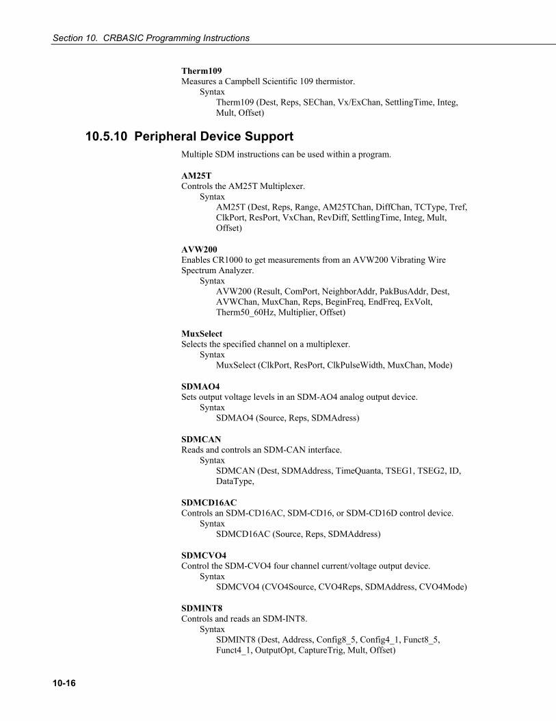
Section 10. CRBASIC Programming Instructions
10-16
Therm109 Measures a Campbell Scientific 109 thermistor.
Syntax Therm109 (Dest, Reps, SEChan, Vx/ExChan, SettlingTime, Integ, Mult, Offset)
10.5.10 Peripheral Device Support Multiple SDM instructions can be used within a program.
AM25T Controls the AM25T Multiplexer.
Syntax AM25T (Dest, Reps, Range, AM25TChan, DiffChan, TCType, Tref, ClkPort, ResPort, VxChan, RevDiff, SettlingTime, Integ, Mult, Offset)
AVW200 Enables CR1000 to get measurements from an AVW200 Vibrating Wire Spectrum Analyzer.
Syntax AVW200 (Result, ComPort, NeighborAddr, PakBusAddr, Dest, AVWChan, MuxChan, Reps, BeginFreq, EndFreq, ExVolt, Therm50_60Hz, Multiplier, Offset)
MuxSelect Selects the specified channel on a multiplexer.
Syntax MuxSelect (ClkPort, ResPort, ClkPulseWidth, MuxChan, Mode)
SDMAO4 Sets output voltage levels in an SDM-AO4 analog output device.
Syntax SDMAO4 (Source, Reps, SDMAdress)
SDMCAN Reads and controls an SDM-CAN interface.
Syntax SDMCAN (Dest, SDMAddress, TimeQuanta, TSEG1, TSEG2, ID, DataType,
SDMCD16AC Controls an SDM-CD16AC, SDM-CD16, or SDM-CD16D control device.
Syntax SDMCD16AC (Source, Reps, SDMAddress)
SDMCVO4 Control the SDM-CVO4 four channel current/voltage output device.
Syntax SDMCVO4 (CVO4Source, CVO4Reps, SDMAddress, CVO4Mode)
SDMINT8 Controls and reads an SDM-INT8.
Syntax SDMINT8 (Dest, Address, Config8_5, Config4_1, Funct8_5, Funct4_1, OutputOpt, CaptureTrig, Mult, Offset)

Section 10. CRBASIC Programming Instructions
10-17
SDMIO16 Sets up and measures an SDM-IO16 control port expansion device.
Syntax SDMIO16 (Dest, Status, Address, Command, Mode Ports 16-13, Mode Ports 12-9, Mode Ports 8-5, Mode Ports 4-1, Mult, Offset)
SDMSIO4 Controls and transmits / receives data from an SDM-SIO4 Interface.
Syntax SDMSIO4 (Dest, Reps, SDMAddress, Mode, Command, Param1, Param2, ValuesPerRep, Multiplier, Offset)
SDMSpeed Changes the rate the CR1000 uses to clock SDM data.
Syntax SDMSpeed (BitPeriod)
SDMSW8A Controls and reads an SDM-SW8A.
Syntax SDMSW8A (Dest, Reps, SDMAddress, FunctOp, SW8AStartChan, Mult, Offset)
SDMTrigger Synchronize when SDM measurements on all SDM devices are made.
Syntax
SDMX50 Allows individual multiplexer switches to be activated independently of the TDR100 instruction.
Syntax SDMX50 (SDMAddress, Channel)
TDR100 Directly measures TDR probes connected to the TDR100 or via an SDMX50.
Syntax TDR100 (Dest, SDMAddress, Option, Mux/ProbeSelect, WaveAvg, Vp, Points, CableLength, WindowLength, ProbeLength, ProbeOffset, Mult, Offset)
TimedControl Allows a sequence of fixed values and durations to be controlled by the SDM task sequencer enabling SDM-CD16x (see Appendix F.6) control events to occur at a precise time.
Syntax TimedControl (Size, SyncInterval, IntervalUnits, DefaultValue, CurrentIndex, Source, ClockOption)

Section 10. CRBASIC Programming Instructions
10-18
10.6 Processing and Math Instructions 10.6.1 Mathematical Operators
Program declaration AngleDegrees (Sec 12.1) sets math functions to use degrees instead of radians.
^ Raise to PowerResult is always promoted to a float to avoid problems that may occur when raising an integer to a negative power. However, loss of precision occurs if result is > 24 bits.
For example:
(46340 ^ 2) will yield 2,147,395,584 (not precisely correct)
whereas
(46340 * 46340) will yield 2,147,395,600 (precisely correct)
Simply use repeated multiplications instead of ^ operators when full 32-bit precision is required.
Same functionality as PWR instruction (12.6.4).
* Multiply / Divide
Use INTDV to retain 32-bit precision + Add - Subtract = Equals <> Not Equal > Greater Than < Less Than >= Greater Than or Equal <= Less Than or Equal
Bit Shift Operators
Bit shift operators (<< and >>) allow the program to manipulate the positions of patterns of bits within an integer (CRBASIC Long type). Here are some example expressions and the expected results:
&B00000001 << 1 produces &B00000010 (decimal 2) &B00000010 << 1 produces &B00000100 (decimal 4) &B11000011 << 1 produces &B10000110 (decimal 134) &B00000011 << 2 produces &B00001100 (decimal 12) &B00001100 >> 2 produces &B00000011 (decimal 3)
The result of these operators is the value of the left hand operand with all of its bits moved by the specified number of positions. The resulting "holes" are filled with zeroes.
NOTE

Section 10. CRBASIC Programming Instructions
10-19
Consider a sensor or protocol that produces an integer value that is a composite of various "packed" fields. This approach is quite common in order to conserve bandwidth and/or storage space. Consider the following example of an eight byte value:
bits 7-6: value_1 bits 5-4: value_2 bits 3-0: value_3
Code to extract these values is shown in EXAMPLE 10.6-1.
EXAMPLE 10.6-1. CRBASIC Code: Using bit shift operators.
Dim input_val as LONG Dim value_1 as LONG Dim value_2 as LONG Dim value_3 as LONG 'read input_val somehow value_1 = (input_val AND &B11000000) >> 6 value_2 = (input_val AND &B00110000) >> 4 'note that value_3 does not need to be shifted value_3 = (input_val AND &B00001111)
With unsigned integers, shifting left is the equivalent of multiplying by two and shifting right is the equivalent of dividing by two.
<< Bit shift left Syntax Variable = Numeric Expression >> Amount >> Bit shift right Syntax Variable = Numeric Expression >> Amount
10.6.2 Logical Operators AND Used to perform a logical conjunction on two expressions.
Syntax result = expr1 AND expr2
NOT Performs a logical negation on an expression.
Syntax result = NOT expression
OR Used to perform a logical disjunction on two expressions.
Syntax result = expr1 OR expr2

Section 10. CRBASIC Programming Instructions
10-20
XOR Performs a logical exclusion on two expressions.
Syntax result = expr1 XOR expr2
IIF Evaluates a variable or expression and returns one of two results based on the outcome of that evaluation.
Syntax Result = IIF (Expression, TrueValue, FalseValue)
IMP Performs a logical implication on two expressions.
Syntax result = expression1 IMP expression2
10.6.3 Trigonometric Functions 10.6.3.1 Derived Functions
TABLE 10.6-1 is a list of trigonometric functions that can be derived from functions intrinsic to CRBASIC.
TABLE 10.6-1. Derived Trigonometric Functions
Function CRBASIC Equivalent Secant Sec = 1 / Cos(X) Cosecant Cosec = 1 / Sin(X) Cotangent Cotan = 1 / Tan(X) Inverse Secant Arcsec = Atn(X / Sqr(X * X - 1)) + Sgn(Sgn(X) -
1) * 1.5708 Inverse Cosecant Arccosec = Atn(X / Sqr(X * X - 1)) + (Sgn(X) - 1)
* 1.5708 Inverse Cotangent Arccotan = Atn(X) + 1.5708 Hyperbolic Secant HSec = 2 / (Exp(X) + Exp(-X)) Hyperbolic Cosecant HCosec = 2 / (Exp(X) - Exp(-X)) Hyperbolic Cotangent HCotan = (Exp(X) + Exp(-X)) / (Exp(X) - Exp(-
X)) Inverse Hyperbolic Sine HArcsin = Log(X + Sqr(X * X + 1)) Inverse Hyperbolic Cosine
HArccos = Log(X + Sqr(X * X - 1))
Inverse Hyperbolic Tangent
HArctan = Log((1 + X) / (1 - X)) / 2
Inverse Hyperbolic Secant
HArcsec = Log((Sqr(-X * X + 1) + 1) / X)
Inverse Hyperbolic Cosecant
HArccosec = Log((Sgn(X) * Sqr(X * X + 1) + 1) / X)
Inverse Hyperbolic Cotangent
HArccotan = Log((X + 1) / (X - 1)) / 2
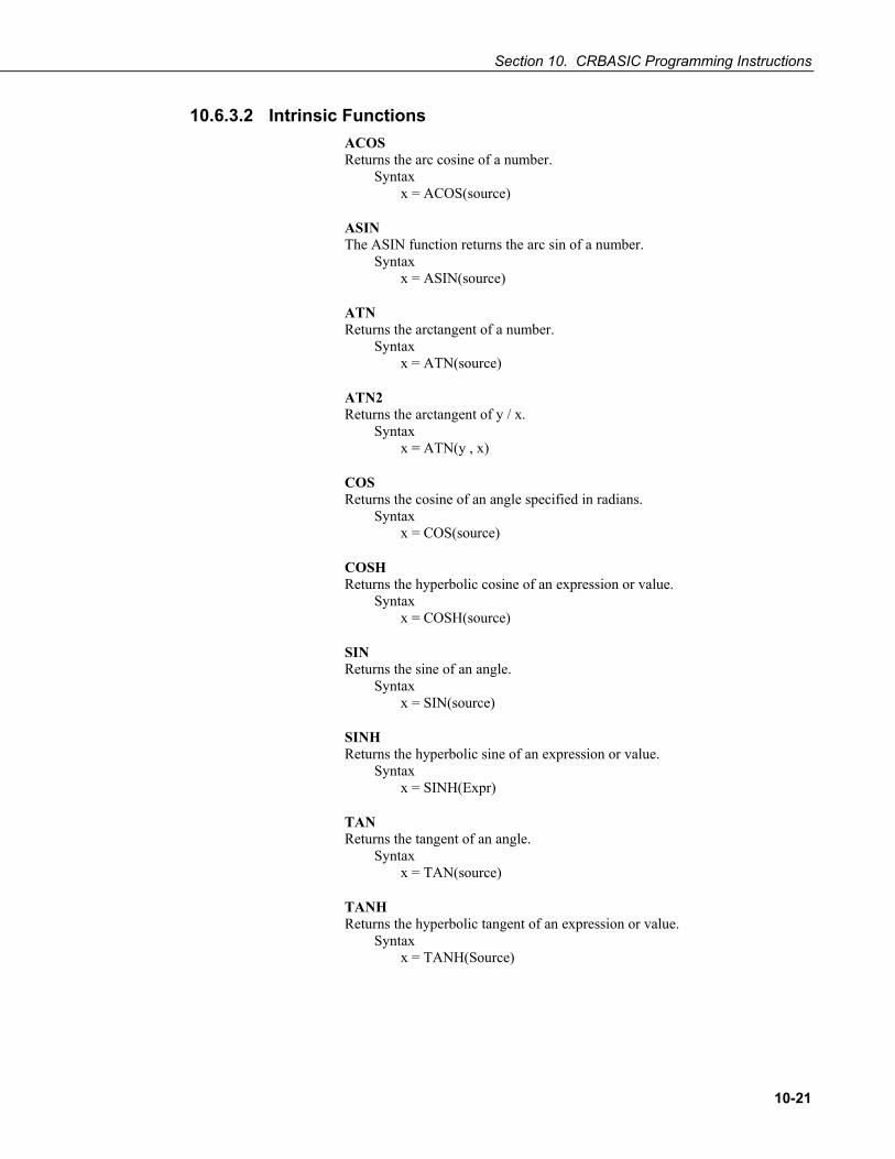
Section 10. CRBASIC Programming Instructions
10-21
10.6.3.2 Intrinsic Functions ACOS Returns the arc cosine of a number.
Syntax x = ACOS(source)
ASIN The ASIN function returns the arc sin of a number.
Syntax x = ASIN(source)
ATN Returns the arctangent of a number.
Syntax x = ATN(source)
ATN2 Returns the arctangent of y / x.
Syntax x = ATN(y , x)
COS Returns the cosine of an angle specified in radians.
Syntax x = COS(source)
COSH Returns the hyperbolic cosine of an expression or value.
Syntax x = COSH(source)
SIN Returns the sine of an angle.
Syntax x = SIN(source)
SINH Returns the hyperbolic sine of an expression or value.
Syntax x = SINH(Expr)
TAN Returns the tangent of an angle.
Syntax x = TAN(source)
TANH Returns the hyperbolic tangent of an expression or value.
Syntax x = TANH(Source)

Section 10. CRBASIC Programming Instructions
10-22
10.6.4 Arithmetic Functions ABS Returns the absolute value of a number.
Syntax x = ABS(source)
Ceiling Rounds a value to a higher integer.
Syntax variable = Ceiling(Number)
EXP Returns e (the base of natural logarithms) raised to a power
Syntax x = EXP(source)
Floor Rounds a value to a lower integer.
Syntax variable = Floor(Number)
FRAC Returns the fractional part of a number.
Syntax x = FRAC(source)
INT or FIX Return the integer portion of a number.
Syntax x = INT(source) x = Fix(source)
INTDV Performs an integer division of two numbers.
Syntax X INTDV Y
LN or LOG Returns the natural logarithm of a number. Ln and Log perform the same function.
Syntax x = LOG(source) x = LN(source)
LOGN = LOG(X) / LOG(N)
LOG10 The LOG10 function returns the base 10 logarithm of a number.
Syntax x = LOG10 (number)
NOTE

Section 10. CRBASIC Programming Instructions
10-23
MOD Divides two numbers and returns only the remainder.
Syntax result = operand1 MOD operand2
PWR Performs an exponentiation on a variable. Same functionality as ^ operator (6.6.1).
Syntax PWR (X, Y)
RectPolar Converts from rectangular to polar coordinates.
Syntax RectPolar (Dest, Source)
Round Rounds a value to a higher or lower number.
Syntax variable = Round (Number, Decimal)
SGN Finds the sign value of a number.
Syntax x = SGN(source)
Sqr Returns the square root of a number.
Syntax x = SQR(number)
10.6.5 Integrated Processing DewPoint Calculates dew point temperature from dry bulb and relative humidity.
Syntax DewPoint (Dest, Temp, RH)
PRT Calculates temperature from the resistance of an RTD.
Syntax PRT (Dest, Reps, Source, Mult, Offset)
SatVP Calculates saturation vapor pressure (kPa) from temperature.
Syntax SatVP (Dest, Temp)
StrainCalc Converts the output of a bridge measurement instruction to microstrain.
Syntax StrainCalc (Dest, Reps, Source, BrZero, BrConfig, GF, v)

Section 10. CRBASIC Programming Instructions
10-24
VaporPressure Calculates vapor pressure from temperature and relative.
Syntax VaporPressure (Dest, Temp, RH)
WetDryBulb Calculates vapor pressure (kPa) from wet and dry bulb temperatures and barometric pressure.
Syntax WetDryBulb (Dest, DryTemp, WetTemp, Pressure)
10.6.6 Spatial Processing AvgSpa Computes the spatial average of the values in the source array.
Syntax AvgSpa (Dest, Swath, Source)
CovSpa Computes the spatial covariance of sets of data.
Syntax CovSpa (Dest, NumOfCov, SizeOfSets, CoreArray, DatArray)
FFTSpa Performs a Fast Fourier Transform on a time series of measurements.
Syntax FFTSpa (Dest, N, Source, Tau, Units, Option)
MaxSpa Finds the maximum value in an array.
Syntax MaxSpa (Dest, Swath, Source)
MinSpa Finds the minimum value in an array.
Syntax MinSpa (Dest, Swath, Source)
RMSSpa Computes the RMS (root mean square) value of an array.
Syntax RMSSpa (Dest, Swath, Source)
SortSpa Sorts the elements of an array in ascending order.
Syntax SortSpa (Dest, Swath, Source)
StdDevSpa Used to find the standard deviation of an array.
Syntax StdDevSpa (Dest, Swath, Source)

Section 10. CRBASIC Programming Instructions
10-25
10.6.7 Other Functions AddPrecise Used in conjunction with MovePrecise, allows high precision totalizing of variables or manipulation of high precision variables.
Syntax AddPrecise (PrecisionVariable, X)
AvgRun Stores a running average of a measurement.
Syntax AvgRun (Dest, Reps, Source, Number)
Randomize Initializes the random-number generator.
Syntax Randomize (source)
RND Generates a random number.
Syntax RND (source)
10.7 String Functions & Concatenates string variables + Concatenates string and numeric variables - Compares two strings, returns zero if identical
10.7.1 String Operations String Constants
Constant strings can be used in expressions using quotation marks, i.e. FirstName = “Mike”
String Addition Strings can be concatenated using the ‘+’ operator, i.e
FullName = FirstName + “ “ + MiddleName + “ “ + LastName
String Subtraction String1-String2 results in an integer in the range of -255..+255.
String Conversion to / from Numeric Conversion of Strings to Numeric and Numeric to Strings is done automatically when an assignment is made from a string to a numeric or a numeric to a string, if possible.
String Comparison Operators The comparison operators =, >,<,<>, >= and <= operate on strings.
String Output Processing The Sample () instruction will convert data types if source data type is different than the Sample () data type. Strings are disallowed in all output processing instructions except Sample ().
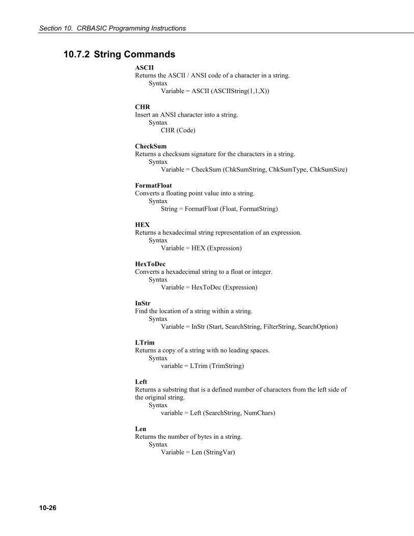
Section 10. CRBASIC Programming Instructions
10-26
10.7.2 String Commands ASCII Returns the ASCII / ANSI code of a character in a string.
Syntax Variable = ASCII (ASCIIString(1,1,X))
CHR Insert an ANSI character into a string.
Syntax CHR (Code)
CheckSum Returns a checksum signature for the characters in a string.
Syntax Variable = CheckSum (ChkSumString, ChkSumType, ChkSumSize)
FormatFloat Converts a floating point value into a string.
Syntax String = FormatFloat (Float, FormatString)
HEX Returns a hexadecimal string representation of an expression.
Syntax Variable = HEX (Expression)
HexToDec Converts a hexadecimal string to a float or integer.
Syntax Variable = HexToDec (Expression)
InStr Find the location of a string within a string.
Syntax Variable = InStr (Start, SearchString, FilterString, SearchOption)
LTrim Returns a copy of a string with no leading spaces.
Syntax variable = LTrim (TrimString)
Left Returns a substring that is a defined number of characters from the left side of the original string.
Syntax variable = Left (SearchString, NumChars)
Len Returns the number of bytes in a string.
Syntax Variable = Len (StringVar)

Section 10. CRBASIC Programming Instructions
10-27
LowerCase Converts a string to all lowercase characters.
Syntax String = LowerCase (SourceString)
Mid Returns a substring that is within a string.
Syntax String = Mid (SearchString, Start, Length)
RTrim Returns a copy of a string with no trailing spaces.
Syntax variable = RTrim (TrimString)
Right Returns a substring that is a defined number of characters from the right side of the original string.
Syntax variable = Right (SearchString, NumChars)
Replace Searches a string for a substring, and replace that substring with a different string.
Syntax variable = Replace (SearchString, SubString, ReplaceString)
StrComp Compares two strings by subtracting the characters in one string from the characters in another
Syntax Variable = StrComp (String1, String2)
SplitStr Splits out one or more strings or numeric variables from an existing string.
Syntax SplitStr (SplitResult, SearchString, FilterString, NumSplit, SplitOption)
Trim Returns a copy of a string with no leading or trailing spaces.
Syntax variable = Trim (TrimString)
UpperCase Converts a string to all uppercase characters
Syntax String = UpperCase (SourceString)
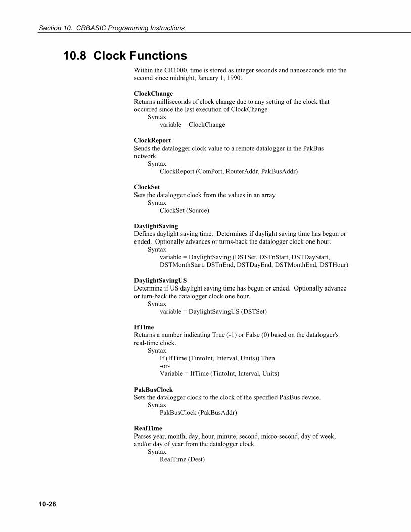
Section 10. CRBASIC Programming Instructions
10-28
10.8 Clock Functions Within the CR1000, time is stored as integer seconds and nanoseconds into the second since midnight, January 1, 1990.
ClockChange Returns milliseconds of clock change due to any setting of the clock that occurred since the last execution of ClockChange.
Syntax variable = ClockChange
ClockReport Sends the datalogger clock value to a remote datalogger in the PakBus network.
Syntax ClockReport (ComPort, RouterAddr, PakBusAddr)
ClockSet Sets the datalogger clock from the values in an array
Syntax ClockSet (Source)
DaylightSaving Defines daylight saving time. Determines if daylight saving time has begun or ended. Optionally advances or turns-back the datalogger clock one hour.
Syntax variable = DaylightSaving (DSTSet, DSTnStart, DSTDayStart, DSTMonthStart, DSTnEnd, DSTDayEnd, DSTMonthEnd, DSTHour)
DaylightSavingUS Determine if US daylight saving time has begun or ended. Optionally advance or turn-back the datalogger clock one hour.
Syntax variable = DaylightSavingUS (DSTSet)
IfTime Returns a number indicating True (-1) or False (0) based on the datalogger's real-time clock.
Syntax If (IfTime (TintoInt, Interval, Units)) Then -or- Variable = IfTime (TintoInt, Interval, Units)
PakBusClock Sets the datalogger clock to the clock of the specified PakBus device.
Syntax PakBusClock (PakBusAddr)
RealTime Parses year, month, day, hour, minute, second, micro-second, day of week, and/or day of year from the datalogger clock.
Syntax RealTime (Dest)

Section 10. CRBASIC Programming Instructions
10-29
SecsSince1990 Returns seconds elapsed since 1990. DataType is LONG. Used with GetRecord ().
Syntax SecsSince1990 (date,option)
TimeIntoInterval Returns a number indicating True (-1) or False (0) based on the datalogger's real-time clock.
Syntax Variable = TimeIntoInterval (TintoInt, Interval, Units) -or- If TimeIntoInterval (TintoInt, Interval, Units)
Timer Returns the value of a timer.
Syntax variable = Timer (TimNo, Units, TimOpt)
10.9 Voice Modem Instructions Refer to the Campbell Scientific voice modem manuals for complete information.
DialVoice Defines the dialing string for a COM310 voice modem.
Syntax DialVoice (DialString)
VoiceBeg, EndVoice Mark the beginning and ending of voice code executed when the datalogger detects a ring from a voice modem.
Syntax VoiceBeg voice code to be executed EndVoice
VoiceHangup Hangs up the voice modem.
Syntax VoiceHangup
VoiceKey Recognizes the return of characters 1 - 9, *, or #. VoiceKey is often used to add a delay, which provides time for the message to be spoken, in a VoiceBegin/EndVoice sequence.
Syntax VoiceKey (TimeOut*IDH_Popup_VoiceKey_Timeout)
VoiceNumber Returns one or more numbers (1 - 9) terminated by the # or * key.
Syntax VoiceNumber (TimeOut*IDH_POPUP_VoiceKey_Timeout)

Section 10. CRBASIC Programming Instructions
10-30
VoicePhrases Provides a list of phrases for VoiceSpeak
Syntax VoicePhrases (PhraseArray, Phrases)
VoiceSetup Controls the hang-up of the COM310 voice modem.
Syntax VoiceSetup (HangUpKey, ExitSubKey, ContinueKey, SecsOnLine, UseTimeout, CallOut)
VoiceSpeak Defines the voice string that should be spoken by the voice modem.
Syntax VoiceSpeak ( "String" + Variable + "String"…, Precision)
10.10 Custom Keyboard and Display Menus Note that custom menus are constructed with the following syntax before the BeginProg instruction. DisplayMenu ("MenuName", AddToSystem) MenuItem ("MenuItemName", Variable) MenuPick (Item1, Item2, Item3...) DisplayValue ("MenuItemName", tablename.fieldname) SubMenu (MenuName) MenuItem ("MenuItemName", Variable) EndSubMenu EndMenu BeginProg (Program Body) EndProg
DisplayMenu … EndMenu Marks the beginning and ending of a custom menu.
Syntax DisplayMenu ("MenuName", AddToSystem) menu definition EndMenu
MenuItem Defines the name and associated measurement value for an item in a custom menu.
Syntax MenuItem ("MenuItemName", Variable)
MenuPick Creates a list of selectable options that can be used when editing a MenuItem value.
Syntax MenuPick (Item1, Item2, Item3...)

Section 10. CRBASIC Programming Instructions
10-31
DisplayValue Defines the name and associated data table value or variable for an item in a custom menu.
Syntax DisplayValue ("MenuItemName", Expression)
SubMenu … EndSubMenu Defines the beginning and ending of a second level menu for a custom menu.
Syntax DisplayMenu ("MenuName", 100) SubMenu ("MenuName") menu definition EndSubMenu EndMenu
10.11 Serial Input / Output Read More! See Section 11.8 Serial Input / Output
MoveBytes Moves binary bytes of data into a different memory location when translating big endian to little endian data.
Syntax MoveBytes (Destination, DestOffset, Source, SourceOffset, NumBytes)
SerialBrk Sends a break signal with a specified duration to a CR1000 serial port.
Syntax SerialBrk (Port, Duration)
SerialClose Closes a communications port that was previously opened by SerialOpen.
Syntax SerialClose (ComPort)
SerialFlush Clears any characters in the serial input buffer.
Syntax SerialFlush (ComPort)
SerialIn Sets up a communications port for receiving incoming serial data.
Syntax SerialIn (Dest, ComPort, TimeOut, TerminationChar, MaxNumChars)
SerialInBlock Stores incoming serial data. This function returns the number of bytes received.
Syntax SerialInBlock (ComPort, Dest, MaxNumberBytes)

Section 10. CRBASIC Programming Instructions
10-32
SerialInChk Returns the number of characters available in the datalogger serial buffer.
Syntax SerialInChk (ComPort)
SerialInRecord Reads incoming serial data on a COM port and stores the data in a destination variable.
Syntax SerialInRecord (COMPort, Dest, SyncChar, NBytes, EndWord, RecsBack)
SerialOpen Sets up a datalogger port for communication with a non-PakBus device.
Syntax SerialOpen (ComPort, BaudRate, Format, TXDelay, BufferSize)
SerialOut Transmits a string over a datalogger communication port.
Syntax SerialOut (ComPort, OutString, WaitString, NumberTries, TimeOut)
SerialOutBlock Send binary data out a communications port. Used to support a transparent serial talk-through mode.
Syntax SerialOutBlock (ComPort, Expression, NumberBytes)
10.12 Peer-to-Peer PakBus Communications Read More! See Section 14 PakBus Overview for more information. Also see Campbell Scientific PakBus Networking Guide available at www.campbellsci.com.
Peer-to-peer PakBus instructions enable the datalogger to communicate with other PakBus devices. Instructions specify a COM port and a PakBus address. If the route to the device is not yet known, a direct route through the specified COM port is first tried. If the route is through a PakBus neighbor that must first be dialed, use DialSequence () to define and establish the route.
The PakBus Address is a variable that can be used in CRBASIC like any other variable.
The ComPort parameter sets a default communications port when a route to the remote node is not known. Enter one of the following commands:
ComRS-232 ComME Com310 ComSDC7 ComSDC8 ComSDC10 ComSDC11 Com1 (C1,C2) Com2 (C3,C4)

Section 10. CRBASIC Programming Instructions
10-33
Com3 (C5,C6) Com4 (C7,C8) Com32 – Com46 (using single-channel expansion peripheral. See Appendix
F.10.1)
Baud rate on asynchronous ports (ComRS-232, ComME, Com1, Com2, Com3, and Com4) will default to 9600 unless set otherwise by SerialOpen (), or if the port is opened by an incoming PakBus packet at some other baud rate.
The baud rate parameter on asynchronous ports is restricted to X = 0 (autobaud), 300, 1200, 4800, 9600, 19200, 38400, 57600, 115200, with 9600 the default. Prefix of (-) invokes autobaud but starting at X; e.g., -1200 first trys at 1200 baud but will autobaud if not initially successful.
In general, PakBus instructions write a result code to a variable indicating success or failure. Success sets the result code to 0. Otherwise, the result code increments. If communication succeeds but an error is detected, a negative result code is set. See CRBASIC Editor Help for an explanation of error codes.
The Timeout parameter in these instructions is in units of 0.01 seconds. If 0 is used, then the default timeout defined by the time of the best route is used. Use PakBusGraph “Hop Metrics” to calculate this time.
For instructions returning a result code, retries can be coded with CRBASIC logic as shown in the GetVariables example in EXAMPLE 10.12-1:
EXAMPLE 10.12-1. CRBASIC Code: Programming for retries in PakBus peer-to-peer communications.
For I = 1 to 3 GetVariables (ResultCode,….) if ResultCode = 0 Exit For Next
These communication instructions wait for a response or timeout before the program moves on to the next instruction. However, they can be used in a SlowSequence scan, which will not interfere with the execution of other program code. Optionally, the ComPort parameter can be negated, which will cause the instruction not to wait for a response or timeout. This will make the instruction execute faster but any data that it retrieves and the result code is set when the communication is complete.
Broadcast Sends a broadcast message to a PakBus network.
Syntax Broadcast (ComPort, Message)
ClockReport Sends the datalogger clock value to a remote datalogger in the PakBus network.
Syntax ClockReport (ComPort, RouterAddr, PakBusAddr)
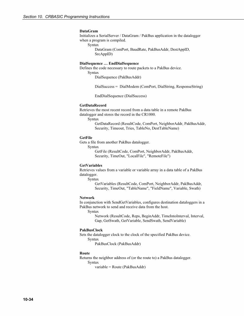
Section 10. CRBASIC Programming Instructions
10-34
DataGram Initializes a SerialServer / DataGram / PakBus application in the datalogger when a program is compiled.
Syntax DataGram (ComPort, BaudRate, PakBusAddr, DestAppID, SrcAppID)
DialSequence … EndDialSequence Defines the code necessary to route packets to a PakBus device.
Syntax DialSequence (PakBusAddr)
DialSuccess = DialModem (ComPort, DialString, ResponseString)
EndDialSequence (DialSuccess)
GetDataRecord Retrieves the most recent record from a data table in a remote PakBus datalogger and stores the record in the CR1000.
Syntax GetDataRecord (ResultCode, ComPort, NeighborAddr, PakBusAddr, Security, Timeout, Tries, TableNo, DestTableName)
GetFile Gets a file from another PakBus datalogger.
Syntax GetFile (ResultCode, ComPort, NeighborAddr, PakBusAddr, Security, TimeOut, "LocalFile", "RemoteFile")
GetVariables Retrieves values from a variable or variable array in a data table of a PakBus datalogger.
Syntax GetVariables (ResultCode, ComPort, NeighborAddr, PakBusAddr, Security, TimeOut, "TableName", "FieldName", Variable, Swath)
Network In conjunction with SendGetVariables, configures destination dataloggers in a PakBus network to send and receive data from the host.
Syntax Network (ResultCode, Reps, BeginAddr, TimeIntoInterval, Interval, Gap, GetSwath, GetVariable, SendSwath, SendVariable)
PakBusClock Sets the datalogger clock to the clock of the specified PakBus device.
Syntax PakBusClock (PakBusAddr)
Route Returns the neighbor address of (or the route to) a PakBus datalogger.
Syntax variable = Route (PakBusAddr)

Section 10. CRBASIC Programming Instructions
10-35
Routes Returns a list of known dynamic routes for a PakBus datalogger that has been configured as a router in a PakBus network.
Syntax Routes (Dest)
SendData Sends the most recent record from a data table to a remote PakBus device.
Syntax SendData (ComPort, RouterAddr, PakBusAddr, DataTable)
SendFile Sends a file to another PakBus datalogger.
Syntax SendFile (ResultCode, ComPort, NeighborAddr, PakBusAddr, Security, TimeOut, "LocalFile", "RemoteFile")
SendGetVariables Sends an array of values to the host PakBus datalogger, and / or retrieve an array of data from the host datalogger.
Syntax SendGetVariables (ResultCode, ComPort, RouterAddr, PakBusAddr, Security, TimeOut, SendVariable, SendSwath, GetVariable, GetSwath)
SendTableDef Sends the table definitions from a data table to a remote PakBus device.
Syntax SendTableDef (ComPort, RouterAddr, PakBusAddr, DataTable)
SendVariables Sends value(s) from a variable or variable array to a data table in a remote datalogger.
Syntax SendVariables (ResultCode, ComPort, RouterAddr, PakBusAddr, Security, TimeOut, "TableName", "FieldName", Variable, Swath)
StaticRoute Defines a static route to a PakBus datalogger.
Syntax StaticRoute (ComPort, NeighborAddr, PakBusAddr)
TimeUntilTransmit The TimeUntilTransmit instruction returns the time remaining, in seconds, before communication with the host datalogger.
Syntax TimeUntilTransmit
10.13 Variable Management FindSpa Searches a source array for a value and returns the value’s position in the array.
Syntax FindSpa (SoughtLow, SoughtHigh, Step, Source)

Section 10. CRBASIC Programming Instructions
10-36
Move Moves the values in a range of variables into difference variables or fills a range of variables with a constant.
Syntax Move (Dest, DestReps, Source, SourceReps)
10.14 File Management Commands to access and manage files stored in CR1000 memory.
CalFile Stores variable data, such as sensor calibration data, from a program into a non-volatile CR1000 memory file (CRD, CPU:drive, or USR: drive). CalFile pre-dates and is not used with the FieldCal function.
Syntax CalFile (Source/Dest, NumVals, "Device:filename", Option)
FileCopy Copies a file from one drive to another.
Syntax FileCopy (FromFileName, ToFileName)
FileClose Closes a FileHandle created by FileOpen.
Syntax FileClose (FileHandle)
FileEncrypt Performs an encrypting algorithm on the file. Allows distribution of CRBASIC files without exposing source code.
Syntax Boolean Variable = FileEncrypt (FileName)
FileList Returns a list of files that exist on the specified drive.
Syntax FileList (Drive,DestinationArray)
FileManage Manages program files from within a running datalogger program.
Syntax FileManage ("Device: FileName", Attribute)
FileOpen Opens an ASCII text file or a binary file for writing or reading.
Syntax FileHandle = FileOpen ("FileName", "Mode", SeekPoint)
FileRead Reads a file referenced by FileHandle and stores the results in a variable or variable array.
Syntax FileRead (FileHandle, Destination, Length)

Section 10. CRBASIC Programming Instructions
10-37
FileReadLine Reads a line in a file referenced by a FileHandle and stores the result in a variable or variable array.
Syntax FileReadLine (FileHandle, Destination, Length)
FileRename Changes the name of file on the CR1000’s CPU:, USR:, or CRD: drives.
Syntax FileRename (drive:OldFileName, drive:NewFileName)
FileSize Returns the size of the file in the previously opened file referenced by the FileHandle parameter.
Syntax FileSize (FileHandle)
FileTime Returns the time the file specified by the FileHandle was created.
Syntax Variable = FileTime (FileHandle)
FileWrite Writes ASCII or binary data to a file referenced in the program by FileHandle.
Syntax FileWrite (FileHandle, Source, Length)
Include Inserts code from a file (Filename) at the position of the Include () instruction at compile time. Include cannot be nested.
Syntax Include ("Device:Filename")
NewFile Determines if a file stored on the datalogger has been updated since the instruction was last run. Typically used with image files.
Syntax NewFile (NewFileVar, “FileName”)
RunProgram Runs a datalogger program file from the active program file.
Syntax RunProgram ("Device:FileName", Attrib)
10.15 Data Table Access and Management Commands to access and manage data stored in data tables, including Public and Status tables.
FileMark Inserts a filemark into a data table.
Syntax FileMark (TableName)

Section 10. CRBASIC Programming Instructions
10-38
GetRecord Retrieves one record from a data table and stores the results in an array. May be used with SecsSince1990 ().
Syntax GetRecord (Dest, TableName, RecsBack)
ResetTable Used to reset a data table under program control.
Syntax ResetTable (TableName)
SetStatus Changes the value for a setting in the datalogger Status table.
Syntax SetStatus ("FieldName", Value)
TableName.FieldName Accesses a specific field from a record in a table
Syntax TableName.FieldName (FieldNameIndex, RecordsBack)
TableName.Output Determine if data was written to a specific DataTable the last time the DataTable was called.
Syntax TableName.Output (1,1)
TableName.Record Determines the record number of a specific DataTable record.
Syntax TableName.Record (1,n)
TableName.TableSize Returns the number of records allocated for a data table
Syntax TableName.TableSize (1,1)
TableName.TableFull Indicates whether a fill and stop table is full or whether a ring-mode table has begun overwriting its oldest data.
Syntax TableName.TableFull (1,1)
TableName.TimeStamp Returns the time into an interval or a timestamp for a record in a specific DataTable.
Syntax TableName.TimeStamp (m,n)
TableName.EventCount Returns the number of data storage events that have occurred for an event driven data table.
Syntax TableName.EventCount (1,1)

Section 10. CRBASIC Programming Instructions
10-39
WorstCase Saves one or more "worst case" data storage events into separate tables. Used in conjunction with DataEvent.
Syntax WorstCase (TableName, NumCases, MaxMin, Change, RankVar)
10.16 Information Services Email, IP SMS, and Web Page Services. These services are available only when the CR1000 is used with network link devices that have the PPP/IP key enabled , i.e., when the CR1000 IP stack is used. See Appendix F.12.3
Read More! See Section 11.2 Information Services.
EMailRecv Polls an SMTP server for email messages and store the message portion of the email in a string variable.
Syntax variable = EMailRecv ("ServerAddr", "ToAddr", "FromAddr", "Subject", Message, "Authen", "UserName", "PassWord", Result)
EMailSend Sends an email message to one or more email addresses via an SMTP server.
Syntax variable = EMailSend ("ServerAddr", "ToAddr", "FromAddr", "Subject", "Message", "Attach", "UserName", "PassWord", Result)
EthernetPower Controls power state of the NL115 Ethernet Port.
Syntax EthernetPower (state)
FTPClient Sends or retrieves a file via FTP.
Syntax Variable = FTPClient ("IPAddress", "User", "Password", "LocalFileName", "RemoteFileName", PutGetOption)
HTTPOut Defines a line of HTML code to be used in a datalogger generated HTML file.
Syntax WebPageBegin ("WebPageName", WebPageCmd) HTTPOut ("<p>html string to output " + variable + " additional
string to output</p>") HTTPOut ("<p>html string to output " + variable + " additional
string to output</p>") WebPageEnd
IPTrace Writes IP debug messages to a string variable.
Syntax IPTrace (Dest)
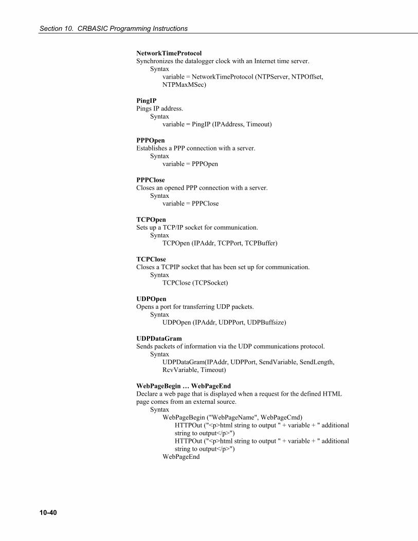
Section 10. CRBASIC Programming Instructions
10-40
NetworkTimeProtocol Synchronizes the datalogger clock with an Internet time server.
Syntax variable = NetworkTimeProtocol (NTPServer, NTPOffset, NTPMaxMSec)
PingIP Pings IP address.
Syntax variable = PingIP (IPAddress, Timeout)
PPPOpen Establishes a PPP connection with a server.
Syntax variable = PPPOpen
PPPClose Closes an opened PPP connection with a server.
Syntax variable = PPPClose
TCPOpen Sets up a TCP/IP socket for communication.
Syntax TCPOpen (IPAddr, TCPPort, TCPBuffer)
TCPClose Closes a TCPIP socket that has been set up for communication.
Syntax TCPClose (TCPSocket)
UDPOpen Opens a port for transferring UDP packets.
Syntax UDPOpen (IPAddr, UDPPort, UDPBuffsize)
UDPDataGram Sends packets of information via the UDP communications protocol.
Syntax UDPDataGram(IPAddr, UDPPort, SendVariable, SendLength, RcvVariable, Timeout)
WebPageBegin … WebPageEnd Declare a web page that is displayed when a request for the defined HTML page comes from an external source.
Syntax WebPageBegin ("WebPageName", WebPageCmd) HTTPOut ("<p>html string to output " + variable + " additional
string to output</p>") HTTPOut ("<p>html string to output " + variable + " additional
string to output</p>") WebPageEnd
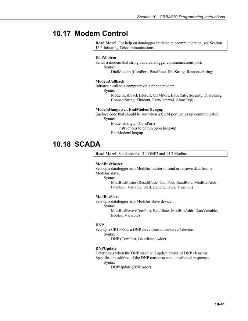
Section 10. CRBASIC Programming Instructions
10-41
10.17 Modem Control Read More! For help on datalogger initiated telecommunication, see Section 13.3 Initiating Telecommunications.
DialModem Sends a modem dial string out a datalogger communications port.
Syntax DialModem (ComPort, BaudRate, DialString, ResponseString)
ModemCallback Initiates a call to a computer via a phone modem.
Syntax ModemCallback (Result, COMPort, BaudRate, Security, DialString, ConnectString, Timeout, RetryInterval, AbortExp)
ModemHangup … EndModemHangup Enclose code that should be run when a COM port hangs up communication.
Syntax ModemHangup (ComPort) instructions to be run upon hang-up EndModemHangup
10.18 SCADA Read More! See Sections 15.1 DNP3 and 15.2 Modbus.
ModBusMaster Sets up a datalogger as a ModBus master to send or retrieve data from a ModBus slave.
Syntax ModBusMaster (ResultCode, ComPort, BaudRate, ModBusAddr, Function, Variable, Start, Length, Tries, TimeOut)
ModBusSlave Sets up a datalogger as a ModBus slave device.
Syntax ModBusSlave (ComPort, BaudRate, ModBusAddr, DataVariable, BooleanVariable)
DNP Sets up a CR1000 as a DNP slave (outstation/server) device.
Syntax DNP (ComPort, BaudRate, Addr)
DNPUpdate Determines when the DNP slave will update arrays of DNP elements. Specifies the address of the DNP master to send unsolicited responses.
Syntax DNPUpdate (DNPAddr)

Section 10. CRBASIC Programming Instructions
10-42
DNPVariable Sets up the DNP implementation in a DNP slave CR1000.
Syntax DNPVariable (Array, Swath, Object, Variation, Class, Flag, Event Expression, Number of Events)
10.19 Calibration Functions Calibrate Used to force calibration of the analog channels under program control.
Syntax Calibrate (Dest, Range) (parameters are optional)
FieldCal Sets up the datalogger to perform a calibration on one or more variables in an array.
Syntax FieldCal (Function, MeasureVar, Reps, MultVar, OffsetVar, Mode, KnownVar, Index, Avg)
SampleFieldCal Stores the values in the FieldCal file to a data table.
Syntax DataTable (TableName, NewFieldCal, Size) SampleFieldCal EndTable
NewFieldCal Triggers storage of FieldCal values when a new FieldCal file has been written.
Syntax DataTable (TableName, NewFieldCal, Size) SampleFieldCal EndTable
LoadFieldCal Loads values from the FieldCal file into variables in the datalogger.
Syntax LoadFieldCal (CheckSig)
FieldCalStrain Sets up the datalogger to perform a zero or shunt calibration for a strain measurement.
Syntax FieldCalStrain (Function, MeasureVar, Reps, GFAdj, ZeromV/V, Mode, KnownRS, Index, Avg, GFRaw, uStrainDest)
10.20 Satellite Systems Programming Instructions for GOES, ARGOS, INMARSAT-C, OMNISAT. Refer to satellite transmitter manuals available at 7www.campbellsci.com.
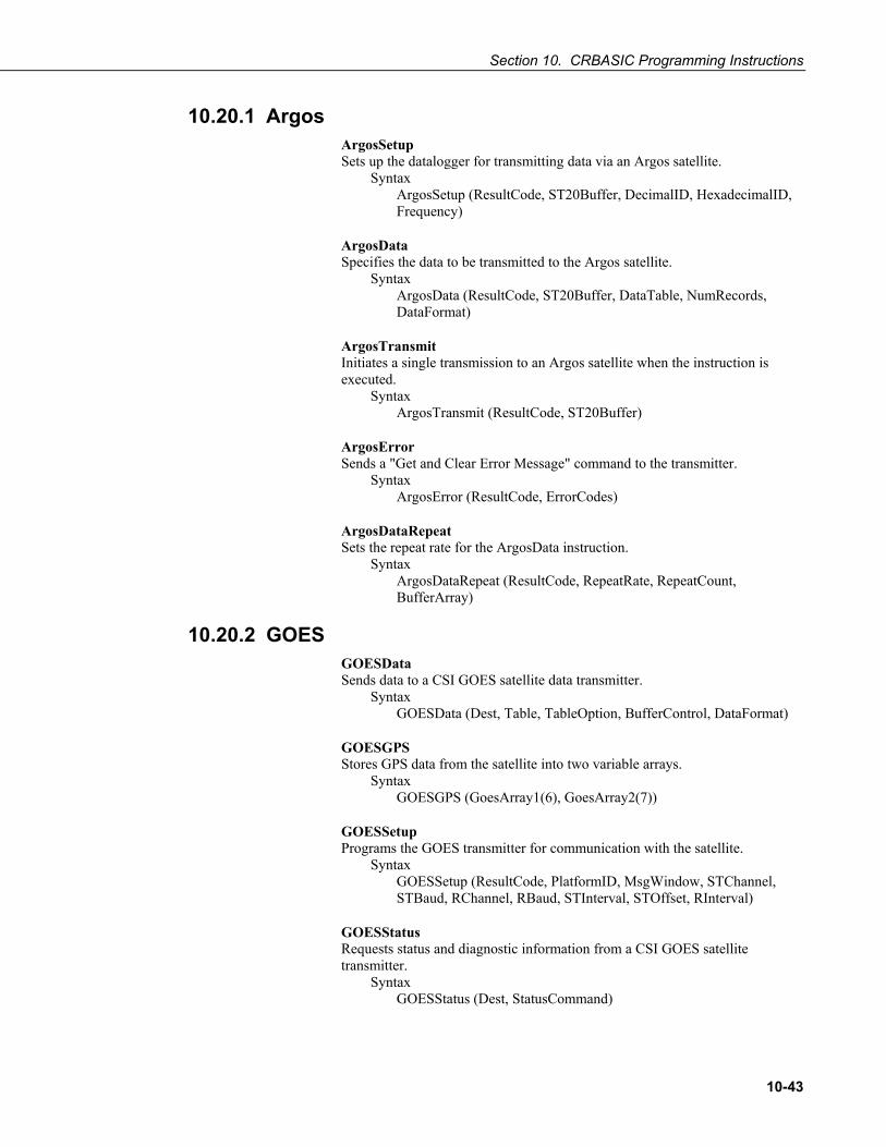
Section 10. CRBASIC Programming Instructions
10-43
10.20.1 Argos ArgosSetup Sets up the datalogger for transmitting data via an Argos satellite.
Syntax ArgosSetup (ResultCode, ST20Buffer, DecimalID, HexadecimalID, Frequency)
ArgosData Specifies the data to be transmitted to the Argos satellite.
Syntax ArgosData (ResultCode, ST20Buffer, DataTable, NumRecords, DataFormat)
ArgosTransmit Initiates a single transmission to an Argos satellite when the instruction is executed.
Syntax ArgosTransmit (ResultCode, ST20Buffer)
ArgosError Sends a "Get and Clear Error Message" command to the transmitter.
Syntax ArgosError (ResultCode, ErrorCodes)
ArgosDataRepeat Sets the repeat rate for the ArgosData instruction.
Syntax ArgosDataRepeat (ResultCode, RepeatRate, RepeatCount, BufferArray)
10.20.2 GOES GOESData Sends data to a CSI GOES satellite data transmitter.
Syntax GOESData (Dest, Table, TableOption, BufferControl, DataFormat)
GOESGPS Stores GPS data from the satellite into two variable arrays.
Syntax GOESGPS (GoesArray1(6), GoesArray2(7))
GOESSetup Programs the GOES transmitter for communication with the satellite.
Syntax GOESSetup (ResultCode, PlatformID, MsgWindow, STChannel, STBaud, RChannel, RBaud, STInterval, STOffset, RInterval)
GOESStatus Requests status and diagnostic information from a CSI GOES satellite transmitter.
Syntax GOESStatus (Dest, StatusCommand)

Section 10. CRBASIC Programming Instructions
10-44
10.20.3 OMNISAT OmniSatSTSetup Sets up the OMNISAT transmitter to send data over the GOES or METEOSAT satellite at a self-timed transmission rate.
Syntax OmniSatSTSetup (ResultCodeST, ResultCodeTX, OmniPlatformID, OmniMsgWindow, OmniChannel, OmniBaud, STInterval, STOffset)
OmniSatRandomSetup Sets up the OMNISAT transmitter to send data over the GOES or METEOSAT satellite at a random transmission rate.
Syntax OmniSatRandomSetup (ResultCodeR, OmniPlatformID, OmniChannel, OmniBaud, RInterval, RCount)
OmniSatData Sends a table of data to the OMNISAT transmitter for transmission via the GOES or METEOSAT satellite.
Syntax OmniSatData (OmniDataResult, TableName, TableOption, OmniBufferCtrl, DataFormat)
OmniSatStatus Queries the transmitter for status information.
Syntax OmniSatStatus (OmniStatusResult)
10.20.4 INMARSAT-C INSATSetup Configures the OMNISAT-I transmitter for sending data over the INSAT-1 satellite.
Syntax INSATSetup (ResultCode, PlatformID, RFPower)
INSATData Sends a table of data to the OMNISAT-I transmitter for transmission via the INSAT-1 satellite.
Syntax INSATData (ResultCode, TableName, TX_Window, TX_Channel)
INSATStatus Queries the transmitter for status information.
Syntax INSATStatus (ResultCode)
10.21 User Defined Functions Function / EndFunction Creates a user defined function.
Syntax Function (optional parameters) optional As DataType
Return (expression) (optional) ExitFunction (optional)
EndFunction

11-1
Section 11. Programming Resource Library
11.1 Field Calibration of Linear Sensors (FieldCal)
Calibration increases accuracy of a measurement device by adjusting its output, or the measurement of its output, to match independently verified quantities. Adjusting the output signal of the sensor is preferred, but not always possible or practical. By using FieldCal () or FieldCalStrain ()in the CR1000 program, a linear output can be calibrated post-measurement by adjusting multiplier and offset.
Once programmed in the CR1000, calibration functions are accessed through a software wizard (LoggerNet / RTDAQ | Datalogger | Calibration Wizard) or through a numeric monitor procedure using keypad or software. The numeric monitor procedure, though somewhat arcane, is utilized in the examples below to illustrate calibration functions and procedures.
Calibration wizards in RTDAQ or LoggerNet 4.0 support FieldCal () and FieldCalStrain ().
11.1.1 CAL Files Calibration data are stored automatically in CAL files in CR1000 memory, which become the source for calibration factors when requested with the LoadFieldCal instruction.
A CAL file is created automatically on the same CR1000 memory drive and given the same name (with .cal extension) as the program that creates and uses it, e.g., CPU:MyProg.CR1 generates CPU:MyProg.cal.
CAL files are created if a program using FieldCal () or FieldCalStrain () does not find an existing compatible CAL file. Files are updated with each successful calibration and contain multiplier and offset factors and information for the LoggerNet / RTDAQ Calibration Wizard. Only if the user creates a data storage output table in the CR1000 program will a calibration history be maintained.
CAL files created by FieldCal () and FieldCalStrain () differ from files created by the CalFile () instruction (Section 10.14 File Management).
NOTE
NOTE

Section 11. Programming Resource Library
11-2
11.1.2 CRBASIC Programming Field calibration functionality is utilized through either:
FieldCal () the principal instruction used for non-strain gage type sensors. For introductory purposes, use of one FieldCalStrain () instruction and a unique set of FieldCalStrain () variables for each sensor to be calibrated is recommended. Use of variable arrays is permitted for more advanced applications,
or
FieldCalStrain () the principal instruction used for strain gages measuring microstrain. Use of one FieldCalStrain () instruction and a unique set of FieldCalStrain () variables for each sensor to be calibrated is recommended. Use of variable arrays is permitted for more advanced applications,
with two supporting instructions:
LoadFieldCal () an optional instruction that evaluates the validity of, and loads values from a CAL file.
SampleFieldCal an optional data storage output instruction that writes the latest calibration values to a data table (not to the CAL file).
and a reserved Boolean variable:
NewFieldCal a reserved Boolean variable under CR1000 control used to optionally trigger a data storage output table one time after a calibration has succeeded.
See CRBASIC Editor Help for operational details on CRBASIC instructions.
11.1.3 Calibration Wizard Overview The LoggerNet / RTDAQ Field Calibration Wizard steps through the calibration process by performing the mode variable changes and measurements automatically. The user sets the sensor to known values and inputs those values into the Wizard.
When a program with FieldCal ()instructions is running, select LoggerNet / RTDAQ | Datalogger | Calibration Wizard” to start the wizard. A list of measurements utilized in any FieldCal instruction in the program is shown.
For more information on using the calibration wizard, consult LoggerNet or RTDAQ Help.
11.1.4 Manual Calibration Overview Manual calibration is presented here to introduce the function of FieldCal () and FieldCalStrain () features in the CR1000. This section is not a comprehensive treatment of field calibration topics. The most comprehensive resource to date covering use of FieldCal () and FieldCalStrain () is RTDAQ software documentation.

Section 11. Programming Resource Library
11-3
Manual calibration is accomplished by changing the value of the FieldCal () or FieldCalStrain () mode variable through the CR1000KD keyboard display or LoggerNet / PC400 / RTDAQ / PC200W numeric monitor. The datalogger does not check for out of bounds values in mode variables. Valid mode variable entries are “1” or “4”.
11.1.4.1 Single-point Calibrations (zero or offset) Use the following general procedure to adjust offsets (y-intercepts) with single-point calibrations:
a. Use a separate FieldCal () instruction and separate related variables for each sensor to be calibrated.
b. Ensure mode variable = 0 or 6 before starting. c. Place the sensor into zeroing or offset condition. d. Set KnownVar variable to the offset or zero value. e. Set mode variable = 1 to start calibration.
Mode Variable Interpretation > 0 and ≠ 6 calibration in progress < 0 calibration encountered an error 2 calibration in process 6 calibration complete.
11.1.4.2 Two-point Calibrations (multiplier / gain) Use the following general procedure to adjust multipliers (slopes) and offsets (y-intercepts) with two-point calibrations:
a. Use a separate FieldCal () instruction and separate related variables for each sensor to be calibrated.
b. Ensure mode variable = 0 or 6 before starting. i. If Mode variable > 0 and ≠ 6 then calibration is in progress.
ii. If Mode variable < 0 then calibration encountered an error. c. Place sensor into first known point condition. d. Set KnownVar variable to first known point. e. Set Mode variable = 1 to start first part of calibration.
i. Mode variable = 2 during the first point calibration. ii. Mode variable = 3 when the first point is completed.
f. Place sensor into second known point condition. g. Set KnownVar variable to second known point. h. Set Mode variable = 4 to start second part of calibration.
i. Mode variable = 5 during second point calibration. ii. Mode variable = 6 when calibration is complete.
11.1.5 FieldCal () Demonstration Programs FieldCal () has the following calibration options:
Zero Offset Two Point Slope and Offset Two Point Slope Only
Demonstration programs are provided as a way to become familiar with the FieldCal () features at the test bench without actual sensors. Sensor signals are

Section 11. Programming Resource Library
11-4
simulated by a CR1000 excitation channel. To reset tests, go to LoggerNet / PC400 / RTDAQ / PC200W | Datalogger | File Control and delete .cal files, then send the demonstration program again to the CR1000.
11.1.5.1 Zero (Option 0) Case: A sensor measures the relative humidity (RH) of air. Multiplier is known to be stable, but sensor offset drifts and requires regular zeroing in a desiccated chamber. The following procedure zeros the RH sensor to obtain the calibration report shown. Use the CR1000KD keyboard or software numeric monitor to change variable values as directed.
Calibration Report for Air RH Sensor
Deployment 30 Day Service
mV Output 1000 1050
Desiccated Chamber 0 % 0 %
Multiplier .05 % / mV .05 % / mV
Offset -50 % -52.5 %
Reading 0 % 0 %
1. EXAMPLE 11.1-1 to the CR1000.
2. To simulate the RH sensor in deployment calibration conditions (desiccated chamber), place a jumper wire between channels VX1 (VX1 (EX1)) and SE8 (4L). Set variable SignalmV to 1000. Set variable KnownRH to 0.0.
3. To simulate the deployment calibration, change the value in variable CalibMode to 1 to start calibration. When CalibMode increments to 6, zero calibration is complete. Calibrated offset will equal -50% at this stage of this example.
4. To continue this example and simulate a zero drift condition, change variable SignalmV to 1050.
5. To simulate 30 day service calibration conditions (desiccated chamber), set variable KnownRH to 0.0. Change the value in variable CalibMode to 1 to start calibration. When CalibMode increments to 6, 30 day service zero calibration is complete. Calibrated offset will equal -52.5%.

Section 11. Programming Resource Library
11-5
EXAMPLE 11.1-1. CRBASIC Code: FieldCal zeroing demonstration program.
'Jumper VX1 (VX1 (EX1)) to SE8(4L) to simulate a sensor Public SignalmV 'Excitation mV Output Public KnownRH 'Known Relative Humidity Public CalMode 'Calibration Trigger Public Multiplier 'Multiplier (Starts at .05 mg / liter / mV, does not change) Public Offset 'Offset (Starts at zero, not changed) Public RH 'Measured Relative Humidity 'Data Storage Output of Calibration Data -- stored whenever a calibration occurs DataTable (CalHist,NewFieldCal,200) SampleFieldCal EndTable BeginProg Multiplier = .05 Offset = 0 LoadFieldCal (true) 'Load the CAL File, if possible Scan (100,mSec,0,0) 'Simulate measurement by exciting channel Vx/VX1 (EX1) ExciteV (Vx1,SignalmV,0) 'Make the calibrated measurement VoltSE (RH,1,mV2500,8,1,0,250,Multiplier,Offset) 'Perform a calibration if CalMode = 1 FieldCal (0,RH,1,Multiplier,Offset,CalMode,KnownRH,1,30) 'If there was a calibration, store it into a data table CallTable (CalHist) NextScan EndProg
11.1.5.2 Offset (Option 1) Case: A sensor measures the salinity of water. Multiplier is known to be stable, but sensor offset drifts and requires regular offset correction using a standard solution. The following procedure offsets the measurement to obtain the calibration report shown.

Section 11. Programming Resource Library
11-6
Calibration Report for Salinity Sensor
Deployment 7 Day Service
mV Output 1350 mV 1345 mV
Standard Solution 30 mg/l 30 mg/l
Multiplier .05 mg/l/mV .05 mg/l/mV
Offset -37.50 mg/l -37.23 mg/l
Reading 30 mg/l 30 mg/l
1. Send the program in EXAMPLE 11.1-2 to the CR1000.
2. To simulate the salinity sensor in deployment calibration conditions (30 mg/l standard solution), place a jumper wire between channels VX1 (VX1 (EX1)) and SE8 (4L). Set variable SignalmV to 1350. Set variable KnownSalt to 30.0.
3. To simulate the deployment calibraton, change the value in variable CalibMode to 1 to start calibration. When CalibMode increments to 6, offset calibration is complete. Calibrated offset will equal -37.48 mg/l at this stage of this example.
4. To continue this example and simulate an offset drift condition, change variable SignalmV to 1345.
5. To simulate 7 day service calibration conditions (30 mg/l standard solution), set variable KnownSalt to 30.0. Change the value in variable CalibMode to 1 to start calibration. When CalibMode increments to 6, 7 day service offset calibration is complete. Calibrated offset will equal -37.23 mg/l.
EXAMPLE 11.1-2. CRBASIC Code: FieldCal offset demonstration program.
'Jumper VX1 (EX1) to SE8(4L) to simulate a sensor Public SignalmV 'Excitation mV Output Public KnownSalt 'Known Salt Concentration Public CalMode 'Calibration Trigger Public Multiplier 'Multiplier (Starts at .05 mg / liter / mV, does not change) Public Offset 'Offset (Starts at zero, not changed) Public SaltContent 'Salt Concentration 'Data Storage Output of Calibration Data -- stored whenever a calibration occurs DataTable (CalHist,NewFieldCal,200) SampleFieldCal EndTable
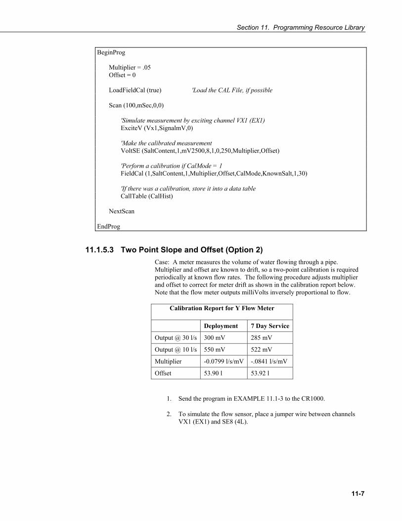
Section 11. Programming Resource Library
11-7
BeginProg Multiplier = .05 Offset = 0 LoadFieldCal (true) 'Load the CAL File, if possible Scan (100,mSec,0,0) 'Simulate measurement by exciting channel VX1 (EX1) ExciteV (Vx1,SignalmV,0) 'Make the calibrated measurement VoltSE (SaltContent,1,mV2500,8,1,0,250,Multiplier,Offset) 'Perform a calibration if CalMode = 1 FieldCal (1,SaltContent,1,Multiplier,Offset,CalMode,KnownSalt,1,30) 'If there was a calibration, store it into a data table CallTable (CalHist) NextScan EndProg
11.1.5.3 Two Point Slope and Offset (Option 2) Case: A meter measures the volume of water flowing through a pipe. Multiplier and offset are known to drift, so a two-point calibration is required periodically at known flow rates. The following procedure adjusts multiplier and offset to correct for meter drift as shown in the calibration report below. Note that the flow meter outputs milliVolts inversely proportional to flow.
Calibration Report for Y Flow Meter
Deployment 7 Day Service
Output @ 30 l/s 300 mV 285 mV
Output @ 10 l/s 550 mV 522 mV
Multiplier -0.0799 l/s/mV -.0841 l/s/mV
Offset 53.90 l 53.92 l
1. Send the program in EXAMPLE 11.1-3 to the CR1000.
2. To simulate the flow sensor, place a jumper wire between channels VX1 (EX1) and SE8 (4L).

Section 11. Programming Resource Library
11-8
3. Simulate deployment calibration conditions (output @ 30 l/s = 300 mV, output @ 10 l/s = 550 mV) in two stages.
i. Set variable SignalmV to 300. Set variable KnownFlow to 30.0.
ii. Start the deployment calibration by setting variable CalibMode = 1.
iii. When CalibMode increments to 3, set variable SignalmV to 550. Set variable KnownFlow to 10.
iv. Resume the deployment calibration by setting variable CalibMode = 4
4. When variable CalibMode increments to 6, the deployment calibration is complete. Calibrated multiplier is -0.08. Calibrated offset is 53.978.
5. To continue this example, simulate a two stage 7 day service calibration wherein both multiplier and offset drift (output @ 30 l/s = 285 mV, output @ 10 l/s = 522 mV).
i. Set variable SignalmV to 285. Set variable KnownFlow to 30.0.
ii. Start the 7 day service calibration by setting variable CalibMode = 1.
iii. When CalibMode increments to 3, set variable SignalmV to 522. Set variable KnownFlow to 10.
iv. Resume the 7 day service calibration by setting variable CalibMode = 4
6. When variable CalibMode increments to 6, the 7 day service calibration is complete. Calibrated multiplier is -0.0842. Calibrated offset is 53.896.
EXAMPLE 11.1-3. CRBASIC Code: FieldCal multiplier and offset demonstration program.
'Jumper Vx/VX1 (EX1) to SE8(4L) to simulate a sensor Public SignalmV 'Excitation mV Output Public KnownFlow 'Known Water Flow Public CalMode 'Calibration Trigger Public Multiplier 'Sensitivity Public Offset 'Offset (Starts at zero, not changed) Public WaterFlow 'Water Flow 'Data Storage Output of Calibration Data stored whenever a calibration occurs DataTable (CalHist,NewFieldCal,200) SampleFieldCal EndTable
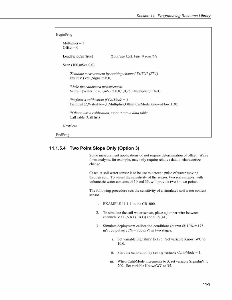
Section 11. Programming Resource Library
11-9
BeginProg Multiplier = 1 Offset = 0 LoadFieldCal (true) 'Load the CAL File, if possible Scan (100,mSec,0,0) 'Simulate measurement by exciting channel Vx/VX1 (EX1) ExciteV (Vx1,SignalmV,0) 'Make the calibrated measurement VoltSE (WaterFlow,1,mV2500,8,1,0,250,Multiplier,Offset) 'Perform a calibration if CalMode = 1 FieldCal (2,WaterFlow,1,Multiplier,Offset,CalMode,KnownFlow,1,30) 'If there was a calibration, store it into a data table CallTable (CalHist) NextScan EndProg
11.1.5.4 Two Point Slope Only (Option 3) Some measurement applications do not require determination of offset. Wave form analysis, for example, may only require relative data to characterize change.
Case: A soil water sensor is to be use to detect a pulse of water moving through soil. To adjust the sensitivity of the sensor, two soil samples, with volumetric water contents of 10 and 35, will provide two known points.
The following procedure sets the sensitivity of a simulated soil water content sensor.
1. EXAMPLE 11.1-1 to the CR1000.
2. To simulate the soil water sensor, place a jumper wire between channels VX1 (VX1 (EX1)) and SE8 (4L).
3. Simulate deployment calibration conditions (output @ 10% = 175 mV, output @ 35% = 700 mV) in two stages.
i. Set variable SignalmV to 175. Set variable KnownWC to 10.0.
ii. Start the calibration by setting variable CalibMode = 1.
iii. When CalibMode increments to 3, set variable SignalmV to 700. Set variable KnownWC to 35.

Section 11. Programming Resource Library
11-10
iv. Resume the calibration by setting variable CalibMode = 4
4. When variable CalibMode increments to 6, the calibration is complete. Calibrated multiplier is 0.0476.
EXAMPLE 11.1-4. CRBASIC Code: FieldCal multiplier only demonstration program.
'Jumper Vx/VX1 (EX1) to SE8(4L) to simulate a sensor Public mV 'Excitation mV Output Public KnownWC 'Known Water Content Public CalMode 'Calibration Trigger Public Multiplier 'Sensitivity Public Offset 'Offset (Starts at zero, not changed) Public RelH2OContent 'Relative Water Content 'Data Storage Output of Calibration Data stored whenever a calibration occurs DataTable (CalHist,NewFieldCal,200) SampleFieldCal EndTable BeginProg Multiplier = 1 Offset = 0 KnownWC = 0 LoadFieldCal (true) 'Load the CAL File, if possible Scan (100,mSec,0,0) 'Simulate measurement by exciting channel Vx/VX1 (EX1) ExciteV (Vx1,mV,0) 'Make the calibrated measurement VoltSE (RelH2OContent,1,mV2500,8,1,0,250,Multiplier,Offset) 'Perform a calibration if CalMode = 1 FieldCal (3,RelH2OContent,1,Multiplier,Offset,CalMode,KnownWC,1,30) 'If there was a calibration, store it into a data table CallTable (CalHist) NextScan EndProg

Section 11. Programming Resource Library
11-11
11.1.6 FieldCalStrain () Demonstration Program Strain gage systems consist of one or more strain gages, a resistive bridge in which the gage resides, and a measurement device such as the CR1000 datalogger. The FieldCalStrain () instruction facilitates shunt calibration of strain gage systems, and is designed exclusively for strain applications wherein microstrain is the unit of measure. The FieldCal () instruction (Section 11.1.5 FieldCal () Demonstration Programs) is typically used in non-microstrain applications.
Shunt calibration of strain gage systems is common practice. However, the technique provides many opportunities for misapplication and misinterpretation. This section is not intended to be a primer on shunt calibration theory, but only to introduce use of the technique with the CR1000 datalogger. Campbell Scientific strongly urges users to study shunt calibration theory from other sources. A thorough treatment of strain gages and shunt calibration theory is available from Vishay at:
http://www.vishay.com/brands/measurements_group/guide/indexes/tn_index.htm
Campbell Scientific applications engineers also have resources that may assist users with strain gage applications.
FieldCalStrain () Shunt Calibration Concepts:
1) Shunt calibration does not calibrate the strain gage itself.
2) Shunt calibration does compensate for long leads and non-linearity in the resistive bridge. Long leads reduce sensitivity because of voltage drop. FieldCalStrain uses the known value of the shunt resistor to adjust the gain (multiplier / span) to compensate. The gain adjustment (S) is incorporated by FieldCalStrain with the manufacturer’s gage factor (GF), becoming the adjusted gage factor (GFadj), which is then used as the gage factor in StrainCalc (). GF is stored in the CAL file and continues to be used in subsequent calibrations. Non-linearity of the bridge is compensated for by selecting a shunt resistor with a value that best simulates a measurement near the range of measurements to be made. Strain gage manufacturers typically specify and supply a range of resistors available for shunt calibration.
3) Shunt calibration verifies the function of the CR1000.
4) The zero function of FieldCalStrain() allows the user to set a particular strain as an arbitrary zero, if desired. Zeroing is normally done after the shunt cal.
Zero and shunt options can be combined through a single CR1000 program.
The following program is provided to demonstrate use of FieldCalStrain () features. If a strain gage configured as shown in FIGURE 11.1-1 is not available, strain signals can be simulated by building the simple circuit shown in FIGURE 11.1-1, substituting a 1000 Ω potentiometer for the strain gage. To reset calibration tests, go to LoggerNet / PC400 / RTDAQ / PC200W | Datalogger | File Control and delete .cal files, then send the demonstration program again to the CR1000.

Section 11. Programming Resource Library
11-12
Case: A 1000 Ω strain gage is placed into a resistive bridge at position R1 as shown in FIGURE 11.1-1. The resulting circuit is a quarter bridge strain gage with alternate shunt resistor (Rc) positions shown. Gage specifications indicate that the gage factor is 2.0, and that with a 249 kΩ shunt, measurement should be about 2000 microstrain.
FIGURE 11.1-1. Quarter bridge strain gage schematic with RC resistor shunt locations shown.
Send Program EXAMPLE 11.1-5 to a CR1000 datalogger.
EXAMPLE 11.1-5. CRBASIC Code: FieldCalStrain () calibration demonstration.
'Program to measure quarter bridge strain gage 'Measurements Public Raw_mVperV Public MicroStrain 'Variables that are arguments in the Zero Function Public Zero_Mode Public Zero_mVperV 'Variables that are arguments in the Shunt Function Public Shunt_Mode Public KnownRes Public GF_Adj Public GF_Raw '---------------------------- Tables---------------------------- DataTable (CalHist,NewFieldCal,50) SampleFieldCal EndTable
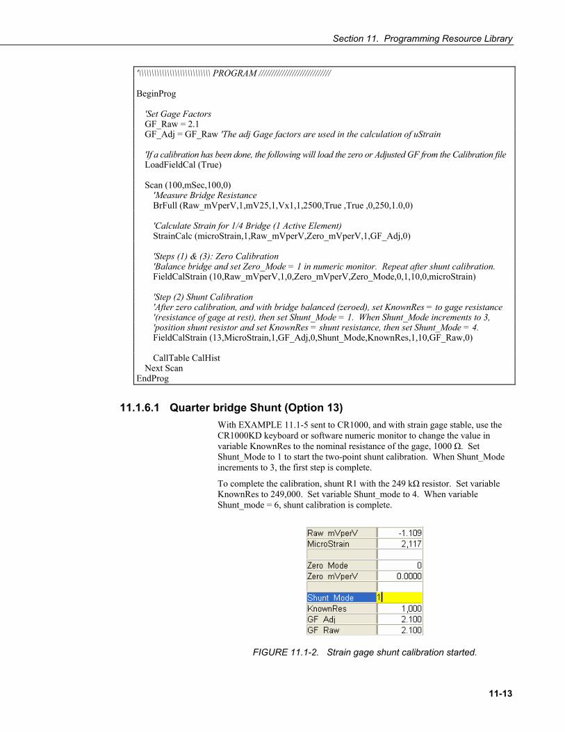
Section 11. Programming Resource Library
11-13
'\\\\\\\\\\\\\\\\\\\\\\\\\\\\ PROGRAM //////////////////////////// BeginProg 'Set Gage Factors GF_Raw = 2.1 GF_Adj = GF_Raw 'The adj Gage factors are used in the calculation of uStrain 'If a calibration has been done, the following will load the zero or Adjusted GF from the Calibration file LoadFieldCal (True) Scan (100,mSec,100,0) 'Measure Bridge Resistance BrFull (Raw_mVperV,1,mV25,1,Vx1,1,2500,True ,True ,0,250,1.0,0) 'Calculate Strain for 1/4 Bridge (1 Active Element) StrainCalc (microStrain,1,Raw_mVperV,Zero_mVperV,1,GF_Adj,0) 'Steps (1) & (3): Zero Calibration 'Balance bridge and set Zero_Mode = 1 in numeric monitor. Repeat after shunt calibration. FieldCalStrain (10,Raw_mVperV,1,0,Zero_mVperV,Zero_Mode,0,1,10,0,microStrain) 'Step (2) Shunt Calibration 'After zero calibration, and with bridge balanced (zeroed), set KnownRes = to gage resistance '(resistance of gage at rest), then set Shunt_Mode = 1. When Shunt_Mode increments to 3, 'position shunt resistor and set KnownRes = shunt resistance, then set Shunt_Mode = 4. FieldCalStrain (13,MicroStrain,1,GF_Adj,0,Shunt_Mode,KnownRes,1,10,GF_Raw,0) CallTable CalHist Next Scan EndProg
11.1.6.1 Quarter bridge Shunt (Option 13) With EXAMPLE 11.1-5 sent to CR1000, and with strain gage stable, use the CR1000KD keyboard or software numeric monitor to change the value in variable KnownRes to the nominal resistance of the gage, 1000 Ω. Set Shunt_Mode to 1 to start the two-point shunt calibration. When Shunt_Mode increments to 3, the first step is complete.
To complete the calibration, shunt R1 with the 249 kΩ resistor. Set variable KnownRes to 249,000. Set variable Shunt_mode to 4. When variable Shunt_mode = 6, shunt calibration is complete.
FIGURE 11.1-2. Strain gage shunt calibration started.

Section 11. Programming Resource Library
11-14
FIGURE 11.1-3. Strain gage shunt calibration finished.
11.1.6.2 Quarter bridge Zero (Option 10) Continuing from 9.8.6.1, keep the 249 kΩ resistor in place to simulate a strain. Using the CR1000KD keyboard or software numeric monitor, change the value in variable Zero_Mode to 1 to start the zero calibration as shown if FIGURE 11.1-4. When Zero_Mode increments to 6, zero calibration is complete as shown in FIGURE 11.1-5.
FIGURE 11.1-4. Starting zero procedure.
FIGURE 11.1-5. Zero procedure finished.

Section 11. Programming Resource Library
11-15
11.2 Information Services Read More! Specific information concerning the use of digital cellular modems for information services can often be found in CSI manuals for those modems for sale through Campbell Scientific.
When used in conjunction with a network link interface that uses the CR1000 IP stack, or a cell modem with the PPP/IP key enabled, the CR1000 has TCP/IP functionality that enables capabilities discussed in this section:
Note: For information on available TCP/IP/PPP devices, refer to Appendix F.12.3 for model numbers. Detailed information on use of TCP/IP/PPP devices is found in their respective manuals and CRBASIC Editor Help.
• PakBus communication over TCP/IP.
• Callback (datalogger initiated communication) using the CRBASIC TCPOpen() function.
• Datalogger-to-datalogger communication.
• HTTP protocol and Web Server.
• FTP Server and Client for transferring files to and from the datalogger.
• TelNet Server for debugging and entry into terminal mode.
• SNMP for NTCIP and RWIS applications.
• PING.
• Micro-serial server using CRBASIC Serial I/O functions with TCP sockets as “COM Ports”.
• Modbus/TCP/IP, Master and Slave.
• DHCP Client to obtain an IP address.
• DNS Client to query a DNS server to map a name into an IP address.
• SMTP to send email messages.
11.2.1 PakBus Over TCP/IP and Callback Once the hardware has been configured, basic PakBus communication over TCP/IP is possible. These functions include sending and retrieving programs, setting the datalogger clock, collecting data, and displaying at the most current record from the CR1000 data tables.
Data callback and datalogger-to-datalogger communications are also possible over TCP/IP. For details and example programs for callback and datalogger-to-datalogger communications, see the network link manual. A listing of network link model number is found in Appendix F.12.3.

Section 11. Programming Resource Library
11-16
11.2.2 HTTP Web Server The CR1000 has a default home page built into the operating system. As shown in FIGURE 11.2-1, this page provides links to the newest record in all tables, including the status table, public table, and data tables. Links are also provided for the last 24 records in each data table. If fewer than 24 records have been stored in a data table, the link will display all data in that table.
FIGURE 11.2-1. CR1000 Default Home Page
Newest Record links refresh automatically every 10 seconds. Last 24 Records link must be manually refreshed to see new data.
Links will also be created automatically for any HTML, XML, and JPEG files found on the datalogger in the CPU:, USR:, and CRD: drives. To copy files to these drives, choose File Control from the LoggerNet / PC400 / RTDAQ / PC200W menu.
Although the default home page cannot be accessed by the user for editing, it can be replaced with HTML code to customize the look of the home page. To replace the default home page, save the new home page under the name default.html and copy it to the datalogger. It can be copied to the CPU:, USR:, or CRD: drive with File Control. Deleting default.html from the datalogger will cause the CR1000 to use its original default home page.
The CR1000 can be programmed to generate HTML or XML code that can be viewed by the web browser. EXAMPLE 11.2-1 shows how to use the CRBASIC keywords WebPageBegin/WebPageEnd and HTTPOut to create HTML code. Note that for HTML code requiring the use of quote marks, CHR(34) is used, while regular quote marks are used to define the beginning and end of alphanumeric strings inside the parentheses of the HTTPOut instruction. For additional information, see the CRBasic editor Help.

Section 11. Programming Resource Library
11-17
EXAMPLE 11.2-1. CRBASIC Code: HTML
'CR1000 Series Datalogger Dim Commands As String * 200 Public Time(9), RefTemp, Public Minutes As String, Seconds As String, Temperature As String DataTable (CR1Temp,True,-1) DataInterval (0,1,Min,10) Sample (1,RefTemp,FP2) Average (1,RefTemp,FP2,False) EndTable 'Default HTML Page WebPageBegin ("default.html",Commands) HTTPOut ("<html>") HTTPOut ("<style>body background-color: oldlace</style>") HTTPOut ("<body><title>Campbell Scientific CR1000 Datalogger</title>") HTTPOut ("<h2>Welcome To the Campbell Scientific CR1000 Web Site!</h2>") HTTPOut ("<tr><td style="+ CHR(34) +"width: 290px"+ CHR(34) +">") HTTPOut ("<a href="+ CHR(34) +"http://www.campbellsci.com"+ CHR(34) +">") HTTPOut ("<img src="+ CHR(34) +"/CPU/SHIELDWEB2.jpg"+ CHR(34) + "width="+ CHR(34) +"128"+CHR(34)+"height="+ CHR(34)+"155"+ CHR(34) + "class="+ CHR(34) +"style1"+ CHR(34) + "/></a></td>") HTTPOut ("<p><h2> Current Data:</h2></p>") HTTPOut ("<p>Time: " + time(4) + ":" + minutes + ":" + seconds + "</p>") HTTPOut ("<p>Temperature: " + Temperature + "</p>") HTTPOut ("<p><h2> Links:</h2></p>") HTTPOut ("<p><a href="+ CHR(34) +"monitor.html"+ CHR(34)+">Monitor</a></p>") HTTPOut ("</body>") HTTPOut ("</html>") WebPageEnd 'Monitor Web Page WebPageBegin ("monitor.html",Commands) HTTPOut ("<html>") HTTPOut ("<style>body background-color: oldlace</style>") HTTPOut ("<body>") HTTPOut ("<title>Monitor CR1000 Datalogger Tables</title>") HTTPOut ("<p><h2>CR1000 Data Table Links</h2></p>") HTTPOut ("<p><a href="+ CHR(34) + "command=TableDisplay&table=CR1Temp&records=10"+ CHR(34)+">Display Last 10 Records from DataTable CR1Temp</a></p>") HTTPOut ("<p><a href="+ CHR(34) + "command=NewestRecord&table=CR1Temp"+ CHR(34) + ">Current Record from CR1Temp Table</a></p>") HTTPOut ("<p><a href="+ CHR(34) + "command=NewestRecord&table=Public"+ CHR(34)+">Current Record from Public Table</a></p>") HTTPOut ("<p><a href="+ CHR(34) + "command=NewestRecord&table=Status"+ CHR(34)+">Current Record from Status Table</a></p>") HTTPOut ("<br><p><a href="+ CHR(34) +"default.html"+CHR(34)+">Back to the Home Page</a></p>") HTTPOut ("</body>") HTTPOut ("</html>") WebPageEnd BeginProg Scan (1,Sec,3,0) PanelTemp (RefTemp,250) RealTime (Time()) Minutes = FormatFloat (Time(5),"%02.0f") Seconds = FormatFloat (Time(6),"%02.0f") Temperature = FormatFloat (RefTemp, "%02.02f") CallTable (CR1Temp) NextScan EndProg

Section 11. Programming Resource Library
11-18
In this example program, the default home page was replaced by using WebPageBegin to create a file called default.html. The new default home page created by the program appears as shown in FIGURE 11.2-2 looks like this:
FIGURE 11.2-2. Home Page Created using WebPageBegin () Instruction
The Campbell Scientific logo in the web page comes from a file called SHIELDWEB2.JPG. That file must be transferred to the datalogger’s CPU drive using File Control. The datalogger can then access the graphic for display on the web page.
A second web page, shown in FIGURE 11.2-3 called monitor.html was created by the example program that contains links to the CR1000 data tables:
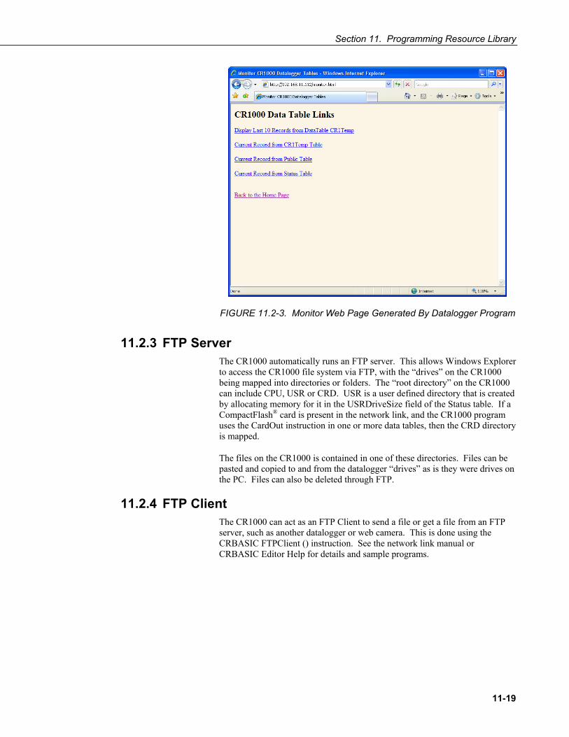
Section 11. Programming Resource Library
11-19
FIGURE 11.2-3. Monitor Web Page Generated By Datalogger Program
11.2.3 FTP Server The CR1000 automatically runs an FTP server. This allows Windows Explorer to access the CR1000 file system via FTP, with the “drives” on the CR1000 being mapped into directories or folders. The “root directory” on the CR1000 can include CPU, USR or CRD. USR is a user defined directory that is created by allocating memory for it in the USRDriveSize field of the Status table. If a CompactFlash® card is present in the network link, and the CR1000 program uses the CardOut instruction in one or more data tables, then the CRD directory is mapped.
The files on the CR1000 is contained in one of these directories. Files can be pasted and copied to and from the datalogger “drives” as is they were drives on the PC. Files can also be deleted through FTP.
11.2.4 FTP Client The CR1000 can act as an FTP Client to send a file or get a file from an FTP server, such as another datalogger or web camera. This is done using the CRBASIC FTPClient () instruction. See the network link manual or CRBASIC Editor Help for details and sample programs.

Section 11. Programming Resource Library
11-20
11.2.5 Telnet Telnet can be used to access the same commands as are available through LoggerNet / PC400 / RTDAQ / PC200W terminal emulator. Start a Telnet session by opening a DOS command prompt and type in:
Telnet xxx.xxx.xxx.xxx <Enter>
where xxx.xxx.xxx.xxx is the IP address of the network device connected to the CR1000.
11.2.6 SNMP Simple Network Management Protocol (SNMP) is a part of the IP suite used by NTCIP and RWIS for monitoring road conditions. The CR1000 supports SNMP when a network device is attached.
11.2.7 Ping Ping can be used to verify that the IP address for the network device connected to the CR1000 is reachable. To use the Ping tool, open a command prompt on a computer connected to the network and type in:
ping xxx.xxx.xxx.xxx <Enter>
where xxx.xxx.xxx.xxx is the IP address of the network device connected to the CR1000.
11.2.8 Micro-Serial Server The CR1000 can be configured to allow serial communication over a TCP/IP port. This is useful when communicating with a serial sensor. See the network link manual and the CRBASIC Editor Help for the TCPOpen () instruction for more information. Information on available network links is available in Appendix F.12.3.
11.2.9 Modbus TCP/IP The CR1000 can perform Modbus communication over TCP/IP using the Modbus TCP/IP interface. To set up Modbus TCP/IP, specify port 502 as the ComPort in the ModBusMaster () and ModBusSlave () instructions. See the CRBASIC Editor Help for more information.
11.2.10 DHCP When connected to a server with a list of IP addresses available for assignment, the CR1000 will automatically request and obtain an IP address through the Dynamic Host Configuration Protocol (DHCP). Once the address is assigned, use DevConfig, PakBus Graph, Connect, or a CR1000KD to look in the CR1000 Status table to see the assigned IP address. This is shown under the field name IPInfo.

Section 11. Programming Resource Library
11-21
11.2.11 DNS The CR1000 provides a Domain Name Server (DNS) client that can query a DNS server to determine if an IP address has been mapped to a hostname. If it has, then the hostname can be used interchangeably with the IP address in some datalogger instructions.
11.2.12 SMTP Simple Mail Transfer Protocol (SMTP) is the standard for e-mail transmissions. The CR1000 can be programmed to send e-mail messages on a regular schedule or based on the occurrence of an event.
11.3 SDI-12 Sensor Support Using the SDI12Recorder () instruction, the CR1000 interrogates SDI-12 sensors attached to terminals C1, C3, C5, and C7. Several SDI-12 probes can be wired to each terminal so long as each probe has a unique address and its own SDI12Recorder instruction.
11.3.1 SDI-12 Transparent Mode System operators can manually interrogate and enter settings in probes using SDI-12 Transparent Mode. Transparent mode is useful in troubleshooting SDI-12 systems because it allows direct communication with SDI-12 probes.
Transparent mode may need to wait for programmed datalogger commands to finish before sending responses. While in the transparent mode, datalogger programs may not execute. Datalogger security may need to be unlocked before transparent mode can be activated.
Transparent mode is entered while the PC is in telecommunications with the datalogger through a terminal emulator program. It is most easily accessed through Campbell Scientific datalogger support software, but is also accessible with terminal emulator programs such as Windows Hyperterminal. Datalogger keyboards and displays cannot be used.
To enter the SDI-12 transparent mode, enter the LoggerNet / PC400 / RTDAQ / PC200W terminal emulator. Click the “Open Terminal” button. A green “Active” indicator appears as shown in FIGURE 11.3-1. Press <Enter> until the CR1000 responds with the prompt “CR1000>”. Type “SDI12” at the prompt (without the quotes) and press <Enter>. In response, the query “Enter Cx Port 1, 3, 5 or 7” will appear. Enter the control port integer to which the SDI-12 sensor is connected. An “Entering SDI12 Terminal” response indicates that SDI-12 Transparent Mode is active.

Section 11. Programming Resource Library
11-22
FIGURE 11.3-1. Entering SDI-12 Transparent Mode through LoggerNet / PC400 / RTDAQ / PC200W Terminal Emulator
11.3.2 SDI-12 Command Basics All commands can be issued through SDI-12 transparent mode.
All commands have three components: sensor address, command body, and command termination.
Sensor address is a single character, and is always the first character of the command or the subsequent response from the sensor. Usually, sensors are shipped from the factory with a default address of zero.
Command body and subsequent responses are shown as a combination of upper and lower case letters. The upper case letters are the fixed portion of the command, while the lower case letters are the variables or values. All commands use an exclamation point (!) as command terminator.
The CR1000 datalogger supports the entire suite of SDI-12 instructions as summarized in TABLE 11.3-1, and defined by the SDI-12 Support Group (www.sdi-12.org). Manufacturers establish the command set a specific sensor will respond. This section discusses the most common commands including: address query, address change, and sensor acknowledgment and identification. Various ways to initiate measurement and report data are also discussed. For assistance with other commands contact a Campbell Scientific Applications Engineer.
11.3.3 Addressing Wiring more than one SDI-12 probe to a single port requires that each probe have a unique address. Since the default address on most probes is 0, additional probes will need the address changed. All SDI-12 version 1.3 probes accept an address of 0 - 9. If more than ten probes are connected to a common port, lower case “a-z”, and upper case “A-Z” may also be used as addresses.

Section 11. Programming Resource Library
11-23
11.3.3.1 Address Query Command If the address of a particular sensor is unknown, use the Address Query command to request the sensor identify itself. Get Unknown Address syntax is “?!” (without the quotation marks), where the question mark is used as a wildcard for the address, followed by the command terminator. The sensor replies to the query with the address, “a”. Carriage-return <CR> and line-feed <LF> are appended to all responses, although these are transparent to the user.
When using Get Unknown Address command, only one sensor can be connected to the SDI-12 / control port.
11.3.3.2 Change Address Command The command body for changing the sensor address is “Ab”, where “b” is the desired new address. Thus the total command string is “aAb!”, where the lower case “a” is the current address, which is followed by the command body and then the command terminator. For example, to change an address from the default address 0, to address 2, the command is “0A2!” In response, the sensor responds with the “new” address “a”, or in this case “2”.
To subsequently change the address of this sensor to 4, the command is “2A4!”
11.3.3.3 Send Identification Command Verify what sensor is being communicated with by using the Send Identification command “I”. If using the default address of zero, the entire command structure is: “0I!” The specific reply from a sensor is defined by the manufacturer, but will include the sensor’s address, the SDI-12 version, and typically the manufacturer’s name, the sensor’s model number and version number. Optionally it may also contain the serial number or other sensor specific information.
An example of a response from the aI! command is:
013NRSYSINC1000001.2101 <CR><LF>
where, Address = 0 SDI-12 version =1.3 Manufacturer = NRSYSINC Sensor model = 100000 Sensor version = 1.2 Serial number = 101
11.3.4 Making Measurements There are two ways to command sensors to take measurements. A standard measurement has the command body of M[v], and the concurrent measurement is initiated with C[v], where “v” is an optional number that allows for variations to the measurement command. For either measurement command, the response from the sensor is in the form of “atttnn”, where
a = the sensor address
ttt = the time, in seconds, until the sensor will have the measurement(s) ready

Section 11. Programming Resource Library
11-24
nn = the number of values is returned in one or more subsequent D commands
The difference between the two commands is with what happens after the response is returned to the logger. When running CRBASIC code, with the standard M[v] command, the datalogger pauses its operations until the time “ttt” expires, after which it immediately polls the sensor for those values, and then continues with the remainder of its program. With the C[v] command, the datalogger continues with its program without pausing, and queries the sensor for its values on subsequent passes through its program (i.e., those that occur after the time “ttt” expires). The datalogger immediately issues another C[v] command to request a measurement, data from which is requested on the next scan. Note that these subsequent scans should be rapid enough that the sensor is still holding those values in its registers before the sensor times out and discards the data. This “time out” period is fixed by the sensor manufacturer. In normal operations of the logger, for either measurement command set, the datalogger issues the subsequent aD0! send data request, without the user needing to request it. In transparent mode, however, the send data command will need to be issued to see the values returned. The send data command is discussed more fully below.
11.3.4.1 Start Measurement Command The command body that tells a sensor to make measurements is in the form M[v]. The [v] is an optional number, between 1 and 9, and if supported by the sensor’s manufacturer will give variants of the basic measurement instruction. Variants might include a way to change the units that the values are reported (e.g., English standard to metric), or perhaps additional values (level and temperature), or maybe a diagnostic of the sensor’s internal battery’s condition. As mentioned before the response is in the form of “atttnn”.
An example of the entire syntax, for a sensor with the address of 5, might be:
5M! 500410
The response (“atttnn”) indicates that address 5 will have data ready in 4 seconds, and will report 10 values.
Using a variation of the measurement command might be 5M7! 500201 For this hypothetical sensor, with [v] = 7, the sensor returns its internal battery voltage. The response could be read as “address 5 will have data ready in 2 seconds, reporting one value.”
11.3.4.2 Start Concurrent Measurement Command This command is new to Version 1.2 or higher of the SDI-12 Specification. Older sensors, older loggers, or new sensors that do not meet v1.2 specifications will likely not support this command
The command body is C[v]. The interpretation of “v” is the same as in the standard measurement command.
After retrieving data from a previous C! command whose timeout for getting data has expired, the CR1000 will immediately issue another C! command instead of waiting to do so in the next scan. By doing so, if the sensor timeout is < the datalogger's scan interval, the C! command is able to retrieve data every scan, i.e., it will pick up the data from the measurement command issued

Section 11. Programming Resource Library
11-25
during the previous scan and, when the timeout has expired, issue the measurement command whose data is retrieved on the subsequent scan.
11.3.4.3 Aborting a Measurement Command If after sending any measurement command (aM[v]! or aC[v]!) to a sensor, but before it issues a response indicating that the data values are ready, a user can abort the measurement by issuing any other valid command to the sensor.
11.3.5 Obtaining Measurement Values 11.3.5.1 Send Data Command
This command is used to get groups of data from the sensor. D0! is normally issued automatically by the datalogger after any measurement command. In transparent mode, the user asserts this command to obtain data. If the expected number of data values are not returned in response to a D0! command, the data logger issues D1!, D2!, etc., until all measurement values are received. The limiting constraint is that the total number of characters that can be returned to a D0! command is 35 characters (or 75 characters for a concurrent command). If the number of characters exceed this limit, then the remainder of the response are obtained with D1!. If that cannot capture the remainder of the response within the 35 character limit, then D2! is issued, and so on.
11.3.5.2 Continuous Measurements Command Sensors that are able to continuously monitor the phenomena to be measured, such as a shaft encoder, do not require a measurement command (e.g., M!). They can be read directly with the R commands (R0!... R9!) If a sensor cannot perform continuous measurements, then it will only respond with the sensor’s address, acknowledging that it has received but cannot comply with the instruction.
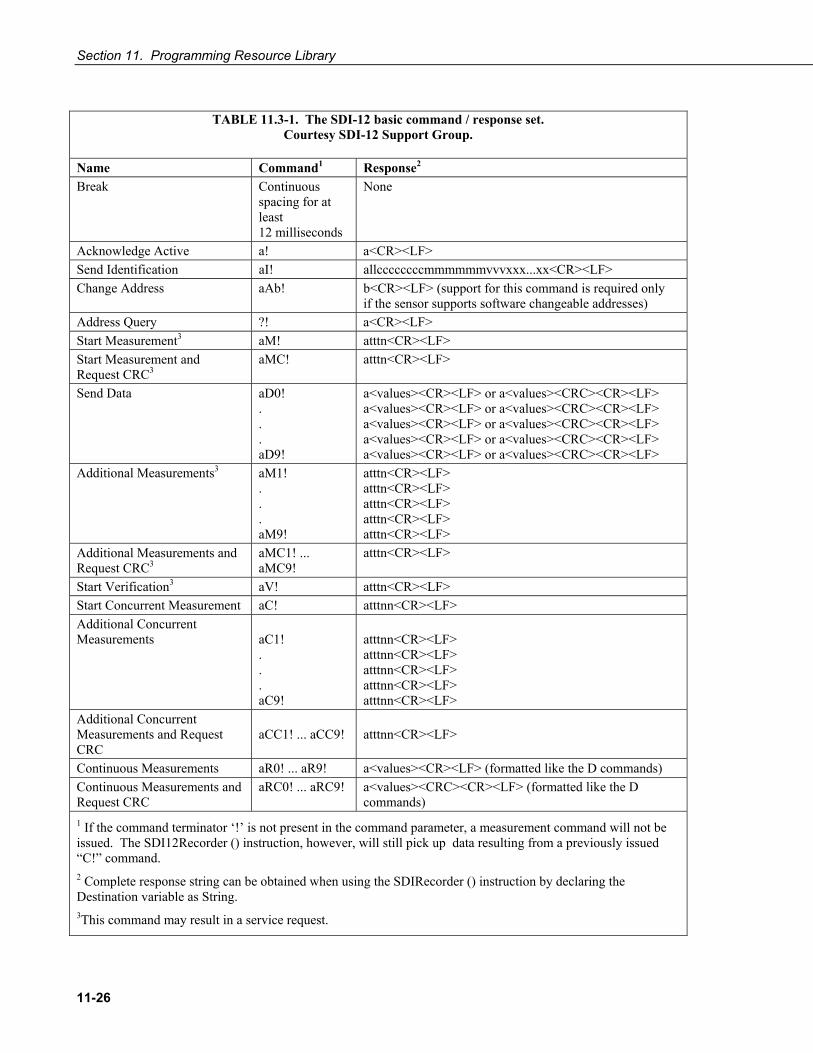
Section 11. Programming Resource Library
11-26
TABLE 11.3-1. The SDI-12 basic command / response set.
Courtesy SDI-12 Support Group.
Name Command1 Response2 Break Continuous
spacing for at least 12 milliseconds
None
Acknowledge Active a! a<CR><LF> Send Identification aI! allccccccccmmmmmmvvvxxx...xx<CR><LF> Change Address aAb! b<CR><LF> (support for this command is required only
if the sensor supports software changeable addresses) Address Query ?! a<CR><LF> Start Measurement3 aM! atttn<CR><LF> Start Measurement and Request CRC3
aMC! atttn<CR><LF>
Send Data aD0! . . . aD9!
a<values><CR><LF> or a<values><CRC><CR><LF> a<values><CR><LF> or a<values><CRC><CR><LF> a<values><CR><LF> or a<values><CRC><CR><LF> a<values><CR><LF> or a<values><CRC><CR><LF> a<values><CR><LF> or a<values><CRC><CR><LF>
Additional Measurements3 aM1! . . . aM9!
atttn<CR><LF> atttn<CR><LF> atttn<CR><LF> atttn<CR><LF> atttn<CR><LF>
Additional Measurements and Request CRC3
aMC1! ... aMC9!
atttn<CR><LF>
Start Verification3 aV! atttn<CR><LF> Start Concurrent Measurement aC! atttnn<CR><LF> Additional Concurrent Measurements
aC1! . . . aC9!
atttnn<CR><LF> atttnn<CR><LF> atttnn<CR><LF> atttnn<CR><LF> atttnn<CR><LF>
Additional Concurrent Measurements and Request CRC
aCC1! ... aCC9!
atttnn<CR><LF>
Continuous Measurements aR0! ... aR9! a<values><CR><LF> (formatted like the D commands) Continuous Measurements and Request CRC
aRC0! ... aRC9! a<values><CRC><CR><LF> (formatted like the D commands)
1 If the command terminator ‘!’ is not present in the command parameter, a measurement command will not be issued. The SDI12Recorder () instruction, however, will still pick up data resulting from a previously issued “C!” command.
2 Complete response string can be obtained when using the SDIRecorder () instruction by declaring the Destination variable as String. 3This command may result in a service request.

Section 11. Programming Resource Library
11-27
11.3.6 SDI-12 Power Considerations When a command is sent by the datalogger to an SDI-12 probe, all probes on the same SDI-12 port will wake up. Only the probe addressed by the datalogger will respond, however, all other probes will remain active until the timeout period expires.
Example
Probe: Water Content
Power Usage: Quiescent: 0.25 mA Measurement: 120 mA Measurement Time: 15 s Active: 66 mA Timeout: 15 s
Probes 1, 2, 3, and 4 are connected to SDI-12 / Control Port 1.
The time line in TABLE 11.3-2 shows a 35 second power usage profile example.
TABLE 11.3-2. Example Power Usage Profile for a Network of SDI-12 Probes
All Time Probes Out milliAmps TotalSec Command Awake Expires 1 2 3 4 mA 1 1M! Yes 120 66 66 66 318 2 120 66 66 66 318 • • • • • • • • • • • • • • • • • • 14 120 66 66 66 318 15 Yes 120 66 66 66 318 16 1D0! Yes 66 66 66 66 264 17 66 66 66 66 264 • • • • • • • • • • • • • • • • • • 29 66 66 66 66 264 30 Yes 66 66 66 66 264 31 0.25 0.25 0.25 0.25 1 • • • • • • • • • • • • • • • • • • 35 0.25 0.25 0.25 0.25 1

Section 11. Programming Resource Library
11-28
For most applications, total power usage of 318 mA for 15 seconds is not excessive, but if 16 probes were wired to the same SDI-12 port, the resulting power draw would be excessive. Spreading sensors over several SDI-12 terminals will help reduce power consumption.
11.4 Subroutines A subroutine is a group of programming instructions that is called by, but runs outside of, the main program. Subroutines are used for the following reasons:
• To reduce program length. Subroutine code can be executed multiple times in a program scan.
• Ease integration of proven code segments into new programs.
• Compartmentalize programs to improve organization.
By executing the Call () instruction, the main program can call a subroutines from anywhere in the program.
A subroutine has access to all global variables. Variables local to a subroutine are declared within the subroutine instruction. Local variables cannot be aliased and are not displayed in the Public table. Global and local variables can share the same name and not conflict. If global variables are passed to local variables of different type, the same type conversion rules apply as apply to conversions among Public or Dim variables.
Programming Tip: To avoid programming conflicts, pass information into local variables and / or define global variables to be used exclusively by a subroutine.
Programming EXAMPLE 11.4-1 shows the use of global and local variables within a simple subroutine. Variables counter() and pi_product are global. Variable i_sub is global but used exclusively by subroutine process. Variables j() and OutVar are local since they are declared as parameters in the Sub instruction,
Sub process(j(4) AS Long,OutVar).
Variable j() is a four element array and variable OutVar is a single element array. The call statement,
Call process (counter(1),pi_product)
passes five values into the subroutine: pi_product and four elements of array counter(). Array counter() is used to pass values into, and extract values from, the subroutine. The variable pi_product is used to extract a value from the subroutine.
Call () passes the values of all listed variables into the subroutine. Values are passed back to the main scan at the end of the subroutine.

Section 11. Programming Resource Library
11-29
EXAMPLE 11.4-1. CRBASIC Code: Subroutine with Global and Local Variables
'Program Purpose: Demonstrates use of global and local variables with subroutines 'Program Function: Passes 2 variables to subroutine. Subroutine increments each 'variable once per second, multiplies each by pi, then passes results back to 'the main program for storage in a data table. 'Global variables '(Used only outside subroutine by choice) Public counter(2) As Long 'Counter in the Main Scan. Public pi_product(2) As Float 'Product of PI * counter(2). 'Global variable '(Used only in subroutine by choice) Public i_sub As Long 'For / Next incrementor used 'in the subroutine. 'Declare Data Table DataTable (pi_results,True,-1) Sample (1,counter(),IEEE4) EndTable 'Declare Subroutine Sub ProcessSub (j(2) As Long,OutVar(2) As Float) 'Declares j(4) as local array '(can only be used in subroutine) For i_sub = 1 To 2 j(i_sub) = j(i_sub) + 1 OutVar(i_sub) = j(i_sub) * 4 * ATN(1) 'Processing to show functionality '(Tip: 4 * ATN(1) = pi to IEEE4 precision) Next i_sub EndSub BeginProg counter(1) = 1 counter(2) = 2 Scan (1,Sec,0,0) Call ProcessSub (counter(),pi_product()) 'Pass Counter() array to j() array, 'pi_pruduct() to OutVar() CallTable pi_results NextScan EndProg 1global variables are those declared anywhere in the program as Public or Dim. 2local variables are those declared in the Sub () instruction.
11.5 Wind Vector 11.5.1 OutputOpt Parameters
In the CR1000 WindVector () instruction, the OutputOpt parameter is used to define the values which are stored. All output options result in an array of values, the elements of which have “_WVc(n)” as a suffix, where n is the element number. The array uses the name of the Speed/East variable as its base. TABLE 11.5-1 lists and describes OutputOpt options.

Section 11. Programming Resource Library
11-30
TABLE 11.5-1. OutputOpt Options
Option Description 0 WVc(1) = Mean horizontal wind speed (S) WVc(2) = Unit vector mean wind direction (Θ1) WVc(3) = Standard deviation of wind direction σ(Θ1). Standard
deviation is calculated using the Yamartino algorithm. This option complies with EPA guidelines for use with straight-line Gaussian dispersion models to model plume transport.
1 WVc(1) = Mean horizontal wind speed (S) WVc(2) = Unit vector mean wind direction (Θ1) 2 WVc(1) = Resultant mean horizontal wind speed ( U )
WVc(2) = Resultant mean wind direction (Θu) WVc(3) = Standard deviation of wind direction σ(Θu). This
standard deviation is calculated using Campbell Scientific's wind speed weighted algorithm. Use of the resultant mean horizontal wind direction is not recommended for straight-line Gaussian dispersion models, but may be used to model transport direction in a variable-trajectory model.
3 WVc(1) = Unit vector mean wind direction (Θ1) 4 WVc(1) = Unit vector mean wind direction (Θ1) WVc(2) = Standard deviation of wind direction σ(Θu). This
standard deviation is calculated using Campbell Scientific's wind speed weighted algorithm. Use of the resultant mean horizontal wind direction is not recommended for straight-line Gaussian dispersion models, but may be used to model transport direction in a variable-trajectory model.
11.5.2 Wind Vector Processing WindVector () processes wind speed and direction measurements to calculate mean speed, mean vector magnitude, and mean vector direction over a data storage interval. Measurements from polar (wind speed and direction) or orthogonal (fixed East and North propellers) sensors are accomodated. Vector direction and standard deviation of vector direction can be calculated weighted or unweighted for wind speed.
When a wind speed measurement is zero, WindVector () uses the measurement to process scalar or resultant vector wind speed and standard deviation, but not the computation of wind direction.
Cup anemometers typically have a mechanical offset which is added to each measurement. A numeric offset is usually encoded in the CRBASIC program to compensate for the mechanical offset. When this is done, a measurement will equal the offset only when wind speed is zero; consequently, additional code is often included to zero the measurement when it equals the offset so that WindVector () can reject measurements when wind speed is zero.
NOTE
Section 11. Programming Resource Library
11-31
Standard deviation can be processed one of two ways: 1) using every sample taken during the data storage interval (enter 0 for the Subinterval parameter), or 2) by averaging standard deviations processed from shorter sub-intervals of the data storage interval. Averaging sub-interval standard deviations minimizes the effects of meander under light wind conditions, and it provides more complete information for periods of transition3.
Standard deviation of horizontal wind fluctuations from sub-intervals is calculated as follows:
σ(Θ) = [((σΘ1)2 + (σΘ2)2 ... + (σΘM)2) / M]1/2
where σ(Θ) is the standard deviation over the data storage interval, and σΘ1 ... σΘM are sub-interval standard deviations.
A sub-interval is specified as a number of scans. The number of scans for a sub-interval is given by:
Desired sub-interval (secs) / scan rate (secs)
For example if the scan rate is 1 second and the data interval is 60 minutes, the standard deviation is calculated from all 3600 scans when the sub-interval is 0. With a sub-interval of 900 scans (15 minutes) the standard deviation is the average of the four sub-interval standard deviations. The last sub-interval is weighted if it does not contain the specified number of scans.
11.5.2.1 Measured Raw Data Si = horizontal wind speed Θi = horizontal wind direction Uei = east-west component of wind Uni = north-south component of wind N = number of samples
3 EPA On-site Meteorological Program Guidance for Regulatory Modeling Applications.

Section 11. Programming Resource Library
11-32
11.5.2.2 Calculations
FIGURE 11.5-1. Input Sample Vectors
In FIGURE 11.5-1, the short, head-to-tail vectors are the input sample vectors described by is and iΘ , the sample speed and direction, or by Uei and Uni, the east and north components of the sample vector. At the end of data storage interval T, the sum of the sample vectors is described by a vector of magnitude U and direction Θu. If the input sample interval is t, the number of samples in data storage interval T is t/TN = . The mean vector magnitude is N/UU = .
Scalar mean horizontal wind speed, S:
S = (Σsi) / N
where in the case of orthogonal sensors:
Si = (Uei2 + Uni
2)1/2
Unit vector mean wind direction, Θ1:
Θ1 = Arctan (Ux / Uy)
where
Ux = (Σsin Θi) / N Uy = (Σcos Θi) / N
or, in the case of orthogonal sensors
Ux = (Σ(Uei / Ui)) / N Uy = (Σ(Uni / Ui)) / N
where Ui = (Uei2 + Uni
2)1/2
sn
Θu
s 2
North
East
U
s1 s3
s 4

Section 11. Programming Resource Library
11-33
Standard deviation of wind direction, σ(Θ1), using Yamartino algorithm:
σ(Θ1) = arc sin(ε)[1 + 0.1547 ε3]
where,
ε = [1-((Ux)2 + (Uy)2)]1/2
and Ux and Uy are as defined above.
Resultant mean horizontal wind speed, U :
U = (Ue2 + Un2)1/2
FIGURE 11.5-2. Mean Wind Vector
where for polar sensors:
Ue = (ΣSi Sin Θi) / N Un = (ΣSi Cos Θi) / N
or, in the case of orthogonal sensors:
Ue = (ΣUei) / N Un = (ΣUni) / N
Resultant mean wind direction, Θu:
Θu = Arctan (Ue / Un)
Standard deviation of wind direction, σ(Θu), using Campbell Scientific algorithm:
σ(Θu) = 81(1 - U / S)1/2
UUn
Ue
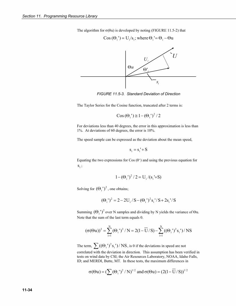
Section 11. Programming Resource Library
11-34
The algorithm for σ(θu) is developed by noting (FIGURE 11.5-2) that
u' where;/sU)'( Cos iiiii Θ−Θ=Θ=Θ
FIGURE 11.5-3. Standard Deviation of Direction
The Taylor Series for the Cosine function, truncated after 2 terms is:
2/)'(1)'( Cos 2ii Θ−≅Θ
For deviations less than 40 degrees, the error in this approximation is less than 1%. At deviations of 60 degrees, the error is 10%.
The speed sample can be expressed as the deviation about the mean speed,
S'ss ii +=
Equating the two expressions for Cos (θ‘) and using the previous equation for
is ;
)S's/(U2/)'(1 ii2
i +=Θ−
Solving for 2i )'(Θ , one obtains;
S/'s2S/'s)'(S/U22)'( ii2
ii2
i +Θ−−=Θ
Summing 2i )'(Θ over N samples and dividing by N yields the variance of Θu.
Note that the sum of the last term equals 0.
∑ ∑= =
Θ−−=Θ=ΘσN
1i
N
1ii
2i
2i
2 NS/)'s)'(()S/U1(2N/)'())u((
The term, ∑ Θ NS/)'s)'(( i2
i , is 0 if the deviations in speed are not correlated with the deviation in direction. This assumption has been verified in tests on wind data by CSI; the Air Resources Laboratory, NOAA, Idaho Falls, ID; and MERDI, Butte, MT. In these tests, the maximum differences in
∑ −=ΘσΘ=Θσ 2/12/12i ))S/U1(2()u( and )N/)'(()u(
si
Θ'iΘu
UiU
Section 11. Programming Resource Library
11-35
have never been greater than a few degrees.
The final form is arrived at by converting from radians to degrees (57.296 degrees/radian).
2/12/1 )S/U1(81))S/U1(2()u( −=−=Θσ
11.6 Custom Menus CR1000 Keyboard / Display menus can be customized to simplify routine operations. Viewing data, toggling control functions, or entering notes are common applications. Individual menu screens support up to eight lines of text with up to 7 variables.
11.6.1 Programming Use the following CRBASIC instructions. Refer to CRBASIC Editor Help for complete information.
DisplayMenu()
Marks the beginning and end of a custom menu. Only one allowed per program. Note: label must be at least 6 characters long to mask default display clock.
EndMenu
Marks the end of a custom menu. Only one allowed per program.
DisplayValue()
Defines a label and displays a value (variable or data table value) not to be edited, such as a measurement.
MenuItem()
Defines a label and displays a variable to be edited by typing or from a pick list defined by MenuPick().
MenuPick()
Creates a pick list from which to edit a MenuItem() variable. Follows immediately after MenuItem(). If variable is declared As Boolean, MenuPick() allows only True or False or declared equivalents. Otherwise, many items are allowed in the pick list. Order of items in list is determined by order in instruction; however, item displayed initially in MenuItem() is determined by the value of the item.
SubMenu()/EndSubMenu Defines the beginning and end of a second level menu. Note: SubMenu() label must be at least 6 characters long to mask default display clock.
11.6.2 Programming Example EXAMPLE 11.6-1 lists CRBASIC programming for a custom menu that facilitates viewing data, entering notes, and controlling a device. FIGURE 11.1-1 through FIGURE 11.6-9 show the organization of the custom menu.

Section 11. Programming Resource Library
11-36
**CUSTOM MENU DEMO** > View Data > Make Notes > Control >
FIGURE 11.6-1. Custom Menu Home from Example 18.6-1
View Data : Ref Temp C |25.7643 TC 1 Temp C |24.3663 TC 2 Temp C |24.2643
FIGURE 11.6-2. View Data Window from Example 18.6-1
Make Notes : Predefined | _____ Free Entry | Accept/Clear| ??????
FIGURE 11.6-3. Make Notes Sub Menu from Example 18.6-1
Predefined Cal_Done Offset_Changed ______
FIGURE 11.6-4. Predfined Notes Pick List from Example 18.6-1
Modify Value Free Entry Current Value: New Value:
FIGURE 11.6-5. Free Entry Notes Window from Example 18.6-1

Section 11. Programming Resource Library
11-37
Accept/Clear Accept Clear
FIGURE 11.6-6. Accept / Clear Notes Window from Example 18.6-1
Control : Count to LED| 0 Manual LED | Off
FIGURE 11.6-7. Control Sub Menu from Example 18.6-1
Count to LED 15 30 45 60
FIGURE 11.6-8. Control LED Pick List from Example 18.6-1
Manual LED On Off
FIGURE 11.6-9. Control LED Manual Boolean Pick List from Example 18.6-1
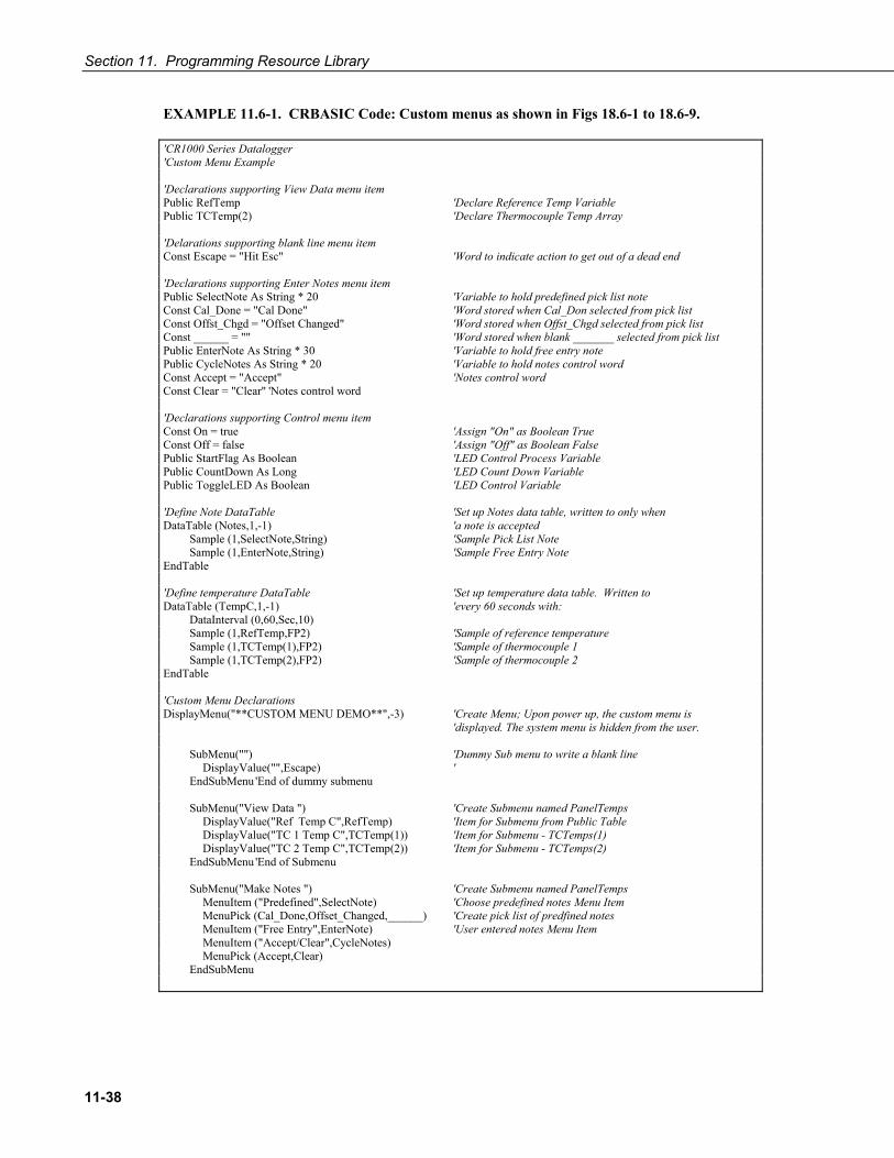
Section 11. Programming Resource Library
11-38
EXAMPLE 11.6-1. CRBASIC Code: Custom menus as shown in Figs 18.6-1 to 18.6-9.
'CR1000 Series Datalogger 'Custom Menu Example 'Declarations supporting View Data menu item Public RefTemp 'Declare Reference Temp Variable Public TCTemp(2) 'Declare Thermocouple Temp Array 'Delarations supporting blank line menu item Const Escape = "Hit Esc" 'Word to indicate action to get out of a dead end 'Declarations supporting Enter Notes menu item Public SelectNote As String * 20 'Variable to hold predefined pick list note Const Cal_Done = "Cal Done" 'Word stored when Cal_Don selected from pick list Const Offst_Chgd = "Offset Changed" 'Word stored when Offst_Chgd selected from pick list Const ______ = "" 'Word stored when blank _______ selected from pick list Public EnterNote As String * 30 'Variable to hold free entry note Public CycleNotes As String * 20 'Variable to hold notes control word Const Accept = "Accept" 'Notes control word Const Clear = "Clear" 'Notes control word 'Declarations supporting Control menu item Const On = true 'Assign "On" as Boolean True Const Off = false 'Assign "Off" as Boolean False Public StartFlag As Boolean 'LED Control Process Variable Public CountDown As Long 'LED Count Down Variable Public ToggleLED As Boolean 'LED Control Variable 'Define Note DataTable 'Set up Notes data table, written to only when DataTable (Notes,1,-1) 'a note is accepted Sample (1,SelectNote,String) 'Sample Pick List Note Sample (1,EnterNote,String) 'Sample Free Entry Note EndTable 'Define temperature DataTable 'Set up temperature data table. Written to DataTable (TempC,1,-1) 'every 60 seconds with: DataInterval (0,60,Sec,10) Sample (1,RefTemp,FP2) 'Sample of reference temperature Sample (1,TCTemp(1),FP2) 'Sample of thermocouple 1 Sample (1,TCTemp(2),FP2) 'Sample of thermocouple 2 EndTable 'Custom Menu Declarations DisplayMenu("**CUSTOM MENU DEMO**",-3) 'Create Menu; Upon power up, the custom menu is 'displayed. The system menu is hidden from the user. SubMenu("") 'Dummy Sub menu to write a blank line DisplayValue("",Escape) ' EndSubMenu 'End of dummy submenu SubMenu("View Data ") 'Create Submenu named PanelTemps DisplayValue("Ref Temp C",RefTemp) 'Item for Submenu from Public Table DisplayValue("TC 1 Temp C",TCTemp(1)) 'Item for Submenu - TCTemps(1) DisplayValue("TC 2 Temp C",TCTemp(2)) 'Item for Submenu - TCTemps(2) EndSubMenu 'End of Submenu SubMenu("Make Notes ") 'Create Submenu named PanelTemps MenuItem ("Predefined",SelectNote) 'Choose predefined notes Menu Item MenuPick (Cal_Done,Offset_Changed,______) 'Create pick list of predfined notes MenuItem ("Free Entry",EnterNote) 'User entered notes Menu Item MenuItem ("Accept/Clear",CycleNotes) MenuPick (Accept,Clear) EndSubMenu

Section 11. Programming Resource Library
11-39
SubMenu("Control ") 'Create Submenu named PanelTemps MenuItem ("Count to LED",CountDown) 'Create menu item CountDown MenuPick(15,30,45,60) 'Create a pick list for CountDown MenuItem ("Manual LED",toggleLED) 'Manual LED control Menu Item MenuPick (On,Off) EndSubMenu EndMenu 'End custom menu creation 'Main Program BeginProg CycleNotes = "??????" 'Initializes Notes Sub Menu, write ????? as a null prompt Scan (1,Sec,3,0) 'Measurements PanelTemp (RefTemp,250) 'Measure Reference Temperature 'Measure Two Thermocouples TCDiff (TCTemp(),2,mV2_5C,1,TypeT,RefTemp,True,0,250,1.0,0) CallTable TempC 'Call data table 'Menu Item "Make Notes" Support Code If CycleNotes = "Accept" Then CallTable Notes 'Write data to Notes data table CycleNotes = "Accepted" 'Write "Accepted" after written to data table Delay (1,500,mSec) 'Pause so user can read "Accepted" SelectNote = "" 'Clear pick list note EnterNote = "" 'Clear free entry note CycleNotes = "??????" 'Write ????? as a null prompt EndIf If CycleNotes = "Clear" Then 'Clear notes when requested SelectNote = "" 'Clear pick list note EnterNote = "" 'Clear free entry note CycleNotes = "??????" 'Write ????? as a null prompt EndIf 'Menu Item "Control" Menu Support Code CountDown = CountDown - 1 'Count down by 1 If CountDown <= 0 'Stop count down from passing 0 CountDown = 0 EndIf If CountDown > 0 Then StartFlag = True 'Indicate that a count down has started EndIf If StartFlag = True AND CountDown = 0 Then 'Interprocess count down and manual LED ToggleLED = True StartFlag = False EndIf If StartFlag = True AND CountDown <> 0 Then 'Interprocess count down and manual LED ToggleLED = False EndIf PortSet (4,ToggleLED) 'Set control port according to result of processing NextScan EndProg
11.7 Conditional Compilation CRBASIC allows definition of conditional code that the compiler interprets and includes at compile time. This feature is useful when the same program code is to be used across multiple datalogger types, e.g., in both the CR1000 and CR3000. Pseudocode for this feature can be written as...

Section 11. Programming Resource Library
11-40
#Const Destination = “CR3000” #If Destination = “CR3000” Then <code specific to the CR3000> #ElseIf Destination = “CR1000” Then <code specific to the CR1000> #Else <code to include otherwise> #EndIf
which allows the simple change of a constant to include the appropriate measurement instructions.
All CRBASIC dataloggers accept program or Include () files with a .DLD extension, which makes it possible to write a single file with conditional compile statements to run in multiple loggers.
Code EXAMPLE 11.7-1 shows a sample program which demonstrates the use of conditional compilation features in CRBASIC using the #If, #ElseIf, #Else and #EndIf commands. Within the program are examples showing the use of the predefined LoggerType constant and associated predefined logger constants (CR3000, CR1000 etc.).
EXAMPLE 11.7-1. Use of Conditional Compile Instructions #If, #ElseIf, #Else and #EndIf
'Conditional Compilation Example for CR3000 / CR1000 / CR800 Series Dataloggers 'Here we choose to set program options based on the 'setting of a constant in the program. Const ProgramSpeed = 2 #If ProgramSpeed = 1 Const ScanRate = 1 '1 Second Const Speed = "1 Second" #ElseIf ProgramSpeed = 2 Const ScanRate = 10 '10 Seconds Const Speed = "10 Second" #ElseIf ProgramSpeed = 3 Const ScanRate = 30 '30 Seconds Const Speed = "30 Second" #Else Const ScanRate = 5 '5 Seconds Const Speed = "5 Second" #EndIf 'Here we choose a COM port depending on which 'logger type the program is running in. #If LoggerType = CR3000 Const SourcSerialPort = Com3 #ElseIf LoggerTypes = CR1000 Const SourcSerialPort = Com2 #ElseIf LoggerType = CR800 Const SourcSerialPort = Com1
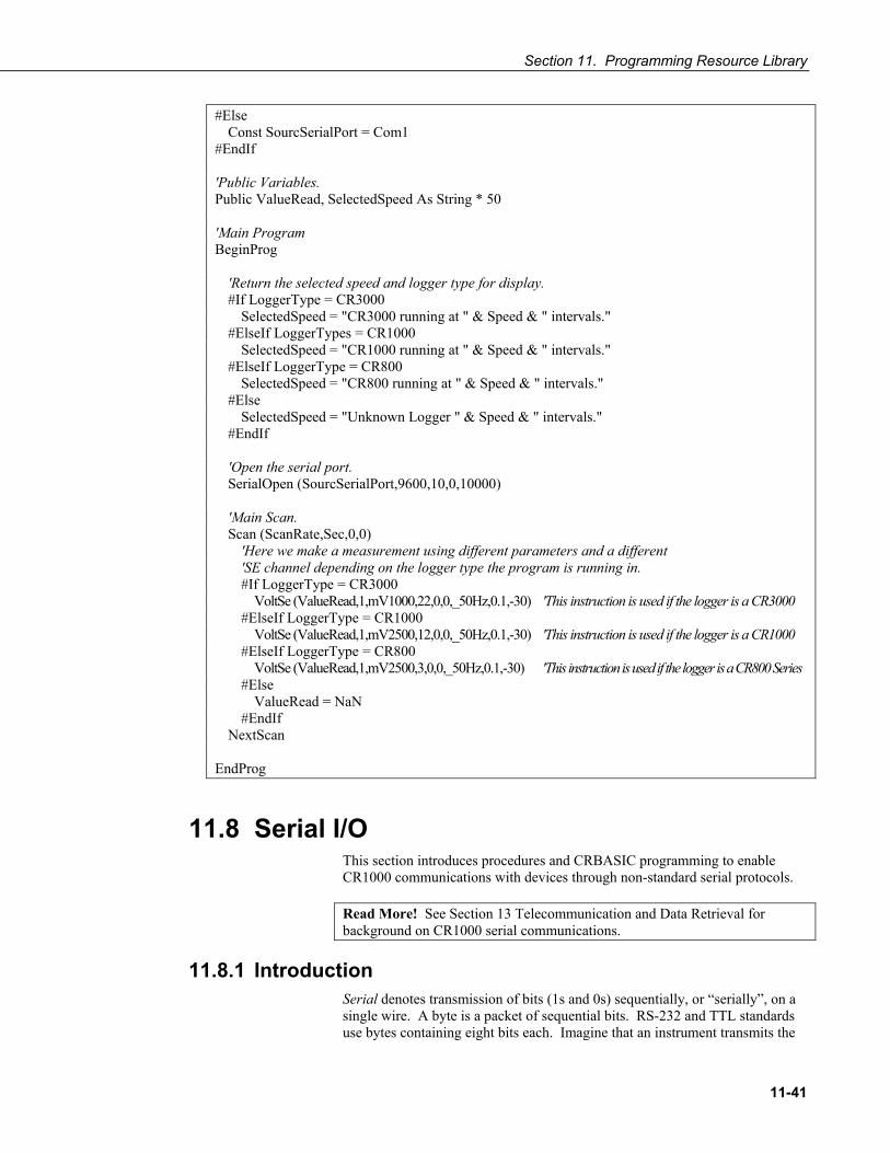
Section 11. Programming Resource Library
11-41
#Else Const SourcSerialPort = Com1 #EndIf 'Public Variables. Public ValueRead, SelectedSpeed As String * 50 'Main Program BeginProg 'Return the selected speed and logger type for display. #If LoggerType = CR3000 SelectedSpeed = "CR3000 running at " & Speed & " intervals." #ElseIf LoggerTypes = CR1000 SelectedSpeed = "CR1000 running at " & Speed & " intervals." #ElseIf LoggerType = CR800 SelectedSpeed = "CR800 running at " & Speed & " intervals." #Else SelectedSpeed = "Unknown Logger " & Speed & " intervals." #EndIf 'Open the serial port. SerialOpen (SourcSerialPort,9600,10,0,10000) 'Main Scan. Scan (ScanRate,Sec,0,0) 'Here we make a measurement using different parameters and a different 'SE channel depending on the logger type the program is running in. #If LoggerType = CR3000 VoltSe (ValueRead,1,mV1000,22,0,0,_50Hz,0.1,-30) 'This instruction is used if the logger is a CR3000 #ElseIf LoggerType = CR1000 VoltSe (ValueRead,1,mV2500,12,0,0,_50Hz,0.1,-30) 'This instruction is used if the logger is a CR1000 #ElseIf LoggerType = CR800 VoltSe (ValueRead,1,mV2500,3,0,0,_50Hz,0.1,-30) 'This instruction is used if the logger is a CR800 Series #Else ValueRead = NaN #EndIf NextScan EndProg
11.8 Serial I/O This section introduces procedures and CRBASIC programming to enable CR1000 communications with devices through non-standard serial protocols.
Read More! See Section 13 Telecommunication and Data Retrieval for background on CR1000 serial communications.
11.8.1 Introduction Serial denotes transmission of bits (1s and 0s) sequentially, or “serially”, on a single wire. A byte is a packet of sequential bits. RS-232 and TTL standards use bytes containing eight bits each. Imagine that an instrument transmits the

Section 11. Programming Resource Library
11-42
byte 11001010 to the CR1000. The instrument does this by translating 11001010 into a series of higher and lower voltages, which it transmits to the CR1000. The CR1000 receives and reconstructs these voltage levels as 11001010. Because an RS-232 or TTL standard was adhered to by both the instrument and the CR1000, the byte successfully passes between them.
If the byte is displayed on a terminal as it was received, it will appear as an ASCII / ANSI character or control code. TABLE 11.8-1 shows a sample of ASCII / ANSI character and code equivalents.
TABLE 11.8-1. ASCII / ANSI Equivalents
Byte
Received
ASCII CharacterDisplayed
DecimalASCII Code
Hex ASCIICode
00110010 2 50 32
1100010 b 98 62
00101011 + 43 2b
00001101 cr 13 d
00000001 1 1
Read More! See Appendix D ASCII / ANSI for a complete list of ASCII / ANSI codes and their binary and hex equivalents.
The byte’s face value, however, is not what is usually of interest. The manufacturer of the instrument must specify what information in the byte is of interest. For instance, two bytes may be received, one for character 2, the other for character b. The pair of characters together, 2b, is the hexadecimal code for “+”, “+” being the information of interest. Or, perhaps, the leading bit, the MSB, on each of two bytes is dropped, the remaining bits combined, and the resulting “superbyte” translated from the remaining bits into a decimal value. The variety of protocols is limited only by the number of instruments on the market. For one in-depth example of how bits may be translated into useable information, see Appendix E. FP2 Data Format.
Tip: ASCII / ANSI control character ff form feed (binary 00001100) causes a terminal screen to clear. This can be frustrating for a developer. Some third party terminal emulator programs, such as Procomm, are useful tools in serial I/O development since they handle this and other idiosyncrasies of serial communication.
When a standardized protocol is used, such as PakBus or Modbus, translation of bytes is relatively easy and transparent. However, when bytes require specialized translation, specialized code is required in the user entered CRBASIC program, and development time can extend into several hours and days.

Section 11. Programming Resource Library
11-43
11.8.2 Serial Ports The CR1000 supports two-way serial communication with other instruments through ports listed in TABLE 11.8-2.
TABLE 11.8-2. CR1000 Serial Ports
Serial Port Voltage Level Logic
RS-232 (9-pin) RS-232 Full duplex asynchronous RS-232
CS I/O (9-pin) TTL Full duplex asynchronous RS-232
COM1 (C1 – C2) TTL Full duplex asynchronous RS-232/TTL
COM2 (C3 – C4) TTL Full duplex asynchronous RS-232/TTL
COM3 (C5 – C6) TTL Full duplex asynchronous RS-232/TTL
COM4 (C7 – C8) TTL Full duplex asynchronous RS-232/TTL
C1 5 VDC SDI-12
C3 5 VDC SDI-12
C5 5 VDC SDI-12
C7 5 VDC SDI-12
C1, C2, C3 5 VDC SDM (used with CSI peripherals only)
11.8.3 Serial Protocols PakBus is the protocol native to the CR1000 and transparently handles routine point-to-point and network communications among CSI dataloggers and PCs. Modbus and DNP3 are standard networking SCADA protocols that optionally operate in the CR1000 with minimal configuration by the user. PakBus, Modbus, and DNP3 operate on the RS-232, CS I/O, and four COM ports. SDI-12 is a protocol used by some smart sensors that requires minimal configuration by the user.
Read More! See Sections 4.7 SDI-12 Recording, 11.3 SDI-12 Sensor Support, Section 14 PakBus Overview, 15.1 DNP3, and 15.2 Modbus.
Many instruments require non-standard protocols to communicate with the CR1000.
Programming Tip! If an instrument or sensor supports SDI-12, Modbus or DNP3, consider using these protocols before programming a custom protocol. These higher level protocols are standardized and, relative to a custom protocol, easy to use. SDI-12, Modbus, and DNP3 also support addressing systems that allow multiplexing of several sensors on a single communications port, which makes for more efficient use of resources.

Section 11. Programming Resource Library
11-44
11.8.4 Terms Asynchronous indicates the sending and receiving devices are not synchronized
using a clock signal.
Baud rate is the rate at which data, plus the start and stop bits, are transmitted. Bits Per Second (BPS) does not account for the start and stop bits.
Big Endian “Big end first.” Placing the most significant integer at the beginning of a numeric word, reading left to right.
cr Carriage Return
Data bits is the number of bits used to describe the data, and fit between the start and stop bits. Sensors typically use 7 or 8 data bits.
Duplex can be half or full. Full duplex is simultaneous, bidirectional data.
lf Line Feed
Little Endian “Little end first.” Placing the most significant integer at the end of a numeric word, reading left to right.
LSB Least significant bit
Marks and Spaces RS232 signal levels are inverted logic compared to TTL. The different levels are called marks and spaces. When referenced to signal ground, the valid RS232 voltage level for a mark is -3 to -25, and for a space is +3 to +25 with -3 to + 3 considered the transition range and meaningless. A mark is a logic 1 and negative voltage. A space is a logic 0 and positive voltage.
MSB Most significant bit
RS-232C refers to the standard used to define the hardware signals and voltage levels. The CR1000 supports several options of serial logic and voltage levels including RS-232 logic at TTL levels and TTL logic at TTL levels.
RX Receive
SP Space
Start bit is the bit used to indicate the beginning of data.
Stop bits is the end of the data bits. The stop bit can be 1, 1.5 or 2.
TX Transmit
11.8.5 CRBASIC Programming To transmit or receive RS-232 or TTL signals, a serial port (see TABLE 11.8-2) must be opened and configured through CRBASIC with the SerialOpen() instruction. The SerialClose() instruction can be used to close the serial port. Below is practical advice regarding the use of SerialOpen() and

Section 11. Programming Resource Library
11-45
SerialClose. Program EXAMPLE 11.8-1 and EXAMPLE 11.8-2 show their use. Consult CRBASIC Editor Help for more information.
SerialOpen (COM Port , Baud Rate , Format , TX Delay , Buffer Size)
Baud rate – baud rate mismatch is frequently a problem when developing a new application. Check for matching baud rates. Some developers prefer to use a fixed baud rate during initial development. When set to a negative value, auto-baud rate detect is enabled. Auto-baud is useful when using the CS I/O and RS232 ports since it will allow the ports to also be used for PC telecommunications.
Format determines data type and if PakBus communications can occur on the COM port. If the port is expected to read sensor data and support normal PakBus telemetry operations, use the auto-baud rate option and ensure the format option supports PakBus communications.
Buffer size The buffer holds data received until it is removed. SerialIn(), SerialInRecord(), and SerialInBlock() instructions are used to read data from the buffer to variables. Once the data is in variables, string manipulation instructions are used to format and parse the data.
SerialClose() must be used before SerialOpen() can be used again to reconfigure the same serial port, or before the port can be used to communicate with a PC.
11.8.5.1 Serial Input Instruction Set Basics SerialOpen1 • Be aware of buffer size (ring memory) • Closes PPP (if active) • Returns TRUE or FALSE when set equal to a Boolean variable
SerialClose • Examples of when to close
– Reopen PPP – Finished setting new settings in a Hayes modem – Finished dialing a modem
• Returns TRUE or FALSE when set equal to a Boolean variable
SerialFlush • Puts the read and write pointers back to the beginning • Returns TRUE or FALSE when set equal to a Boolean variable
SerialIn1 • Can wait on the string until it comes in • Timeout is renewed after each character is received • SerialInRecord tends to obsolete SerialIn. • Buffer size margin (1 extra record + 1 byte).

Section 11. Programming Resource Library
11-46
SerialInBlock1 • For binary data (perhaps integers, floats, data with NULL characters). • Destination can be of any type. • Buffer size margin (1 extra record + 1 byte).
SerialOutBlock1,3 • Binary • Can run in pipeline mode inside the digital measurement task (along with
SDM instructions) if COM1..COM4 and the number of bytes is a constant.
SerialOut • Handy for ASCII command and a known response, e.g., Hayes modem
commands. • Returns 0 if not open else the number of bytes sent.
SerialInRecord2 • Can run in pipeline mode inside the digital measurement task (along with
SDM instructions) if COM1..COM4 and the number of bytes is a constant. • Simplifies synchronization with one way. • Simplifies working with protocols that send a “record” of data with known
start and/or end characters, or a fixed number of records in response to a poll command.
• If a start and end word is not present, then a time gap is the only remaining separator of records. Using Com1..Com4 coincidentally detects a time gap of >100 bits as long as the records are less than 256 bytes.
• Buffer size margin (1 extra record + 1 byte).
1 Processing instructions 2 Measurement instruction in the pipeline mode
3 Measurement instruction if expression evaluates to a constant
11.8.5.2 Serial Input Programming Basics Applications with the purpose of receiving data from another device usually include the following procedures. Other procedures may be required depending on the application.
1. Know what the sensor supports and exactly what the data is. Most sensors work well with TTL voltage levels and RS232 logic. Some things to consider: • Become thoroughly familiar with the data to be captured • Can the sensor be polled? • Does the sensor send data on its own schedule? • Are there markers at the beginning or end of data? Markers are very
useful for identifying a variable length record. • Does the record have a delimiter character, e.g. “,”, spaces or tabs?
These delimeters are useful for parsing the record into usable numbers.
• Will the sensor be sending multiple data strings? Multiple strings usually require filtering before parsing.
• How fast will data be sent to the datalogger? • Is power consumption critical? • Does the sensor compute a checksum? Which type? A checksum is
useful to test for data corruption.

Section 11. Programming Resource Library
11-47
2. Open a serial port (CRBASIC SerialOpen() command) • Example: SerialOpen(Com1,9600,0,0,10000) • Designate the correct port in CRBASIC • Correctly wire the device to the CR1000 • Match the port’s baud rate to the baud rate of the device in CRBASIC.
o Use a fixed baud rate (rather than autobaud) when possible.
3. Receive serial data as a string (CRBASIC SerialIn() or SerialInRecord() command) • Example: SerialInRecord(Com2,SerialInString,42,0,35,””,01) • Declare the string variable large enough to accept the string.
o Example: Public SerialInString As String * 25 • Observe the input string in the input string variable in software
numeric monitor. • NOTE: SerialIn() and SerialInRecord() receive the same data.
SerialInRecord() is generally used for data streaming into the CR1000, while SerialIn is used for data that is received in discrete blocks.
4. Parse (split up) the serial string (CRBASIC SplitStr() Command) • Separates string into numeric and / or string variables. • Example: SplitStr(InStringSplit,SerialInString,"",2,0) • Declare an array to accept the parsed data
o Example: Public InStringSplit(2) As String o Example: Public SplitResult(2) As Float
11.8.5.3 Serial Output Programming Basics Applications with the purpose of transmitting data to another device usually include the following procedures. Other procedures may be required depending on the application.
1. Open a serial port (SerialOpen() command) to configure it for communications. • Parameters are set according to the requirements of the
communications link and the serial device. • Example: SerialOpen (Com1,9600,0,0,10000) • Designate the correct port in CRBASIC • Correctly wire the device to the CR1000 • Match the port’s baud rate to the baud rate of the device in CRBASIC. • Use a fixed baud rate (rather than auto baud) when possible.
2. Build the output string • Example: SerialOutString = “*” & “27.435” & “,” & “56.789” & “#” • Tip: concatenate (add) strings together using & instead of + • Tip: CHR() instruction is used to insert ASCII / ANSI characters into
a string
3. Output string via the serial port (SerialOut() or SerialOutBlock() command) • Example: SerialOut (Com1,SerialOutString,"",0,100) • Declare the output string variable large enough to hold the entire
concatenation. • Example: Public SerialOutString As String * 100

Section 11. Programming Resource Library
11-48
• SerialOut() and SerialOutBlock() output the same data, except that SerialOutBlock transmits null values while SerialOut() strings are terminated by a null value.
11.8.5.4 Translating Bytes One or more of three principle data formats may end up in the SerialInString variable (see examples in Sec. 11.8.3.2). Data may be combinations or variations of all of these. The manufacturer of the instrument must provide the rules by which data are to be decoded.
Alpha-numeric – each digit represents its own alpha-numeric value, i.e., R = the letter R, and 2 = decimal 2. This is the easiest protocol to translate since literal translation arrives complete from the transmitting instrument. It remains to the CRBASIC program to parse (split) the string up and place the values in CR1000 variables. Example (humidity, temperature, and pressure sensor):
SerialInString = “RH= 60.5 %RH T= 23.7 ‘C Tdf= 15.6 ‘C Td= 15.6 ‘C a= 13.0 g/m3 x= 11.1 g/kg Tw= 18.5 ‘C H2O= 17889 ppmV pw=17.81 hPa pws 29.43 hPa h= 52.3 kJ/kg dT= 8.1 ‘C”
Hex Pairs – Bytes are translated to hex pairs, consisting of digits 0 - 9 and letters a – f. Each pair describes a hexadecimal ASCII / ANSI code. Some codes translate to alpha-numeric values, others to symbols or non-printable control characters. Example (Temperature Sensor):
SerialInString = “23 30 31 38 34 0D” (translates to #01 84 cr)
Binary – Bytes are processed on a bit-by-bit basis. Character 0 (Null, &b00) is a valid part of binary data streams. However, the CR1000 uses Null terminated strings, so anytime a Null is received, a string is terminated. The termination is usually premature when reading binary data. To remedy this problem, the SerialInBlock() or SerialInRecord() instruction is required when reading binary data from the serial port buffer to a variable. The variable must be an array set As Long data type, as in, Dim SerialInString As Long
11.8.5.5 Memory Considerations Several points regarding memory should be considered when receiving and processing serial data.
1) Serial buffer. The serial port buffer, which is declared in the SerialOpen() instruction, must be large enough to hold all the data a device will send. The buffer holds the data for subsequent transfer to variables. Allocate extra memory to the buffer when needed, but recognize that added memory to the buffer reduces memory available for long term data storage.

Section 11. Programming Resource Library
11-49
SerialInRecord running in pipeline mode, with the number of bytes parameter = 0. For the digital measurement sequence to know how much room to allocate in the Scan() instruction buffers (default of 3), SerialInRecord has to allocate itself the buffer size specified by SerialOpen (default 10,000, an overkill), or default 3*10,000 = 30K of buffer space. So, while making sure enough bytes are allocated in SerialOpen (the number of bytes per record * ((records/Scan)+1) + at least one extra byte), there is reason not to make the buffer size too large. (Note that if the number of bytes parameter is non-zero, then SerialInRecord needs to allocate itself only this many bytes instead of the number of bytes specified by SerialOpen.)
2) Variable declarations. Variables used to receive data from the serial buffer can be declared as Public or Dim. DIMing variables has the effect of consuming less telecommunications bandwidth. When Public variables are viewed in software, the entire Public table is transferred at the update interval. If the Public table is large, telecommunications bandwidth can be taxed such that other data tables are not collected.
3) String declarations. String variables are memory intensive. Determine how large strings are and declare variables just large enough to hold the string. If the sensor sends multiple strings at once, consider declaring a single string variable and read incoming strings one at a time.
4) The CR1000 adjusts the declared size of strings. One byte is always added to the declared length, which is then increased by up to another 3 bytes to make length divisible by 4.
5) When strings are written to memory, declared string length, not number of characters, determines the memory consumed. Consequently, large strings not filled with characters waste significant memory.
11.8.6 Demonstration Program Program Example 11.8-1is provided as an exercise in serial input / output programming. The example only requires the CR1000 and a single wire jumper between COM1 Tx and COM2 Rx. The program simulates a temperature and relative humidity sensor transmitting RS-232 data out COM1. EXAMPLE 11.8-1 outputs data as an alpha-numeric string.
EXAMPLE 11.8-1. CRBASIC Code: Serial I/O program to receive a simulated RS-232 sensor string. Output string is simulated by the program.
'RS-232 Demonstration Program 'Receive data from a simulated RS-232 sensor to demonstrate RS-232 input / output on a single CR800. Simulated 'air temperature = 27.435 F, relative humidity 56.789 %. 'Wiring: 'COM1 TX (C1) ----- COM2 RX (C4) 'Serial Out Declarations Public TempOut As Float Public RhOut As Float Public SerialOutString As String * 25 'Declare a string variable large enough to ‘hold the output string.
NOTE

Section 11. Programming Resource Library
11-50
'Serial In Declarations Public SerialInString As String * 25 ‘Declare a string variable large enough to ‘hold the output string Public InStringSplit(2) As String ‘Declare strings to accept parsed data. ‘If parsed data is strictly numeric, this array ‘can be declared as Float or Long Alias InStringSplit(1) = TempIn Alias InStringSplit(2) = RhIn 'Main Program BeginProg 'Simulate temperature and RH sensor TempOut = 27.435 'Set simulated temperature to transmit RhOut = 56.789 'Set simulated relative humidity to transmit Scan(5,Sec, 3, 0) 'Serial Out Code 'Transmits string "*27.435,56.789#" out COM1 SerialOpen (Com1,9600,0,0,10000) 'Open a serial port SerialOutString = "*" & TempOut & "," & RhOut & "#" 'Build the output string SerialOut (Com1,SerialOutString,"",0,100) 'Output string via the serial port 'Serial In Code 'Receives string "27.435,56.789" via COM2 'Uses * and # character as filters SerialOpen (Com2,9600,0,0,10000) 'Open a serial port SerialInRecord (Com2,SerialInString,42,0,35,"",01) 'Receive serial data as a string SplitStr (InStringSplit(),SerialInString,"",2,0) 'Parse the serial string NextScan EndProg
11.8.7 Testing Serial I/O Applications A common problem when developing a serial I/O application is the lack of an immediately available serial device with which to develop and test programs. Using HyperTerminal, a developer can simulate the output of a serial device or capture serial input.
HyperTerminal automatically converts binary data to ASCII on the screen. Binary data can be captured, saved to a file, and then viewed with a hexadecimal editor. Other terminal emulators are available from third party vendors that facilitate capture of binary or hex data.
11.8.7.1 Configure HyperTerminal Create a HyperTerminal instance file by clicking Start | All Programs | Accessories | Communications | HyperTerminal. The windows in FIGURE 11.8-1 through FIGURE 11.8-4 are presented. Enter an instance name and click OK.
NOTE

Section 11. Programming Resource Library
11-51
FIGURE 11.8-1. HyperTerminal Connection Description
FIGURE 11.8-2. HyperTerminal Connect To Settings
FIGURE 11.8-3. HyperTerminal COM Port Settings

Section 11. Programming Resource Library
11-52
Click File | Properties | Settings | ASCII Setup... and set as shown.
FIGURE 11.8-4. HyperTerminal ASCII Setup
11.8.7.2 Create Send Text File Create a file from which to send a serial string. The file shown in EXAMPLE 11.8-2 will send the string “[2008:028:10:36:22]C” to the CR1000. Use Notepad or some other text editor that will not place unexpected hidden characters in the file.
EXAMPLE 11.8-2. HyperTerminal Send Text File Example
To send the file, click Transfer | Send Text File | Browse for file, then click OK.
11.8.7.3 Create Text Capture File EXAMPLE 11.8-3 shows a HyperTerminal capture file with some data. The file is empty before use commences.

Section 11. Programming Resource Library
11-53
EXAMPLE 11.8-3. HyperTerminal Text Capture File Example
Engage text capture by clicking on Transfer | Capture Text | Browse, select the file and click OK.
11.8.8 Example Test Program The following test program solves a problem for a specific Campbell Scientific customer. It illustrates one use of CR1000 serial I/O features. The example allows the reader to program a CR1000 to gain experience with serial I/O applications.
Problem: An energy company has a large network of older CR510 dataloggers into which new CR1000 dataloggers are to be incorporated. The CR510 dataloggers are programmed to output data in the legacy Campbell Scientific Printable ASCII format, which satisfies requirements of the customer’s data acquisition system. The network administrator also prefers to synchronize the CR510 clocks from a central computer using the legacy Campbell Scientific ‘C’ command. The CR510 datalogger is hard-coded to output Printable ASCII and recognize the ‘C’ command. CR1000 dataloggers, however, require custom programming to output and accept these same ASCII strings.
Solution: Programming EXAMPLE 11.8-4 imports and exports serial data via the CR1000 RS-232 port. Imported data is expected to have the form of the legacy Campbell Scientific time set ‘C’ command. Exported data has the form of the legacy Campbell Scientific Printable ASCII format.
The RS232 port can be used to download the datalogger program if the SerialOpen() baud rate matches that of CSI datalogger support software (LoggerNet / PC400 / RTDAQ / PC200W). However, two-way PakBus communications will cause the CR1000 to occasionally send unsolicited PakBus packets out the RS232 port for at least 40 seconds after the last PakBus communication. This will produce some “noise” on the intended data output signal.
Monitor the CR1000 RS232 port with the HyperTerminal instance described in Section 11.8.4.1. Send C command file to set the clock according to the text in the file.
The HyperTerminal file will not update automatically with actual time. The file only simulates a clock source.
NOTE
NOTE
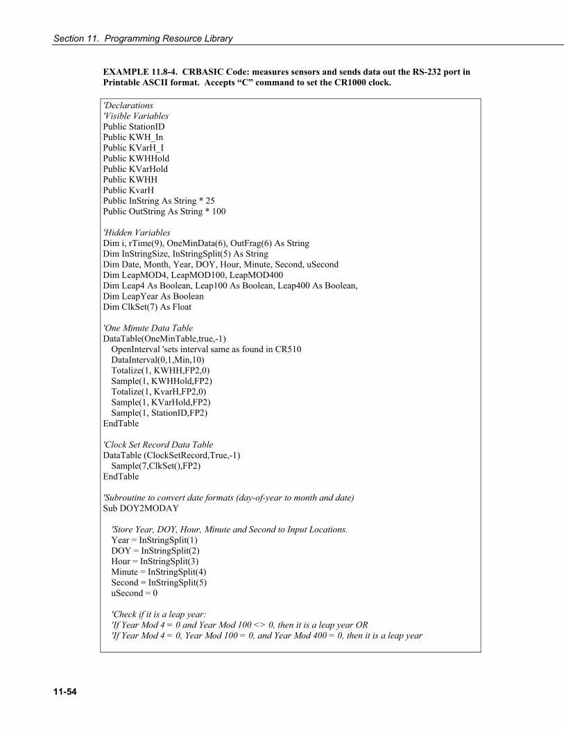
Section 11. Programming Resource Library
11-54
EXAMPLE 11.8-4. CRBASIC Code: measures sensors and sends data out the RS-232 port in Printable ASCII format. Accepts “C” command to set the CR1000 clock.
'Declarations 'Visible Variables Public StationID Public KWH_In Public KVarH_I Public KWHHold Public KVarHold Public KWHH Public KvarH Public InString As String * 25 Public OutString As String * 100 'Hidden Variables Dim i, rTime(9), OneMinData(6), OutFrag(6) As String Dim InStringSize, InStringSplit(5) As String Dim Date, Month, Year, DOY, Hour, Minute, Second, uSecond Dim LeapMOD4, LeapMOD100, LeapMOD400 Dim Leap4 As Boolean, Leap100 As Boolean, Leap400 As Boolean, Dim LeapYear As Boolean Dim ClkSet(7) As Float 'One Minute Data Table DataTable(OneMinTable,true,-1) OpenInterval 'sets interval same as found in CR510 DataInterval(0,1,Min,10) Totalize(1, KWHH,FP2,0) Sample(1, KWHHold,FP2) Totalize(1, KvarH,FP2,0) Sample(1, KVarHold,FP2) Sample(1, StationID,FP2) EndTable 'Clock Set Record Data Table DataTable (ClockSetRecord,True,-1) Sample(7,ClkSet(),FP2) EndTable 'Subroutine to convert date formats (day-of-year to month and date) Sub DOY2MODAY 'Store Year, DOY, Hour, Minute and Second to Input Locations. Year = InStringSplit(1) DOY = InStringSplit(2) Hour = InStringSplit(3) Minute = InStringSplit(4) Second = InStringSplit(5) uSecond = 0 'Check if it is a leap year: 'If Year Mod 4 = 0 and Year Mod 100 <> 0, then it is a leap year OR 'If Year Mod 4 = 0, Year Mod 100 = 0, and Year Mod 400 = 0, then it is a leap year

Section 11. Programming Resource Library
11-55
LeapYear = 0 'Reset leap year status location LeapMOD4 = Year MOD 4 LeapMOD100 = Year MOD 100 LeapMOD400 = Year MOD 400 If LeapMOD4 = 0 Then Leap4 = True Else Leap4 = False If LeapMOD100 = 0 Then Leap100 = True Else Leap100 = False If LeapMOD400 = 0 Then Leap400 = True Else Leap400 = False If Leap4 = True Then LeapYear = True If Leap100 = True Then If Leap400 = True Then LeapYear = True Else LeapYear = False EndIf EndIf Else LeapYear = False EndIf 'If it is a leap year, use this section. If (LeapYear = True) Then Select Case DOY Case Is < 32 Month = 1 Date = DOY Case Is < 61 Month = 2 Date = DOY + -31 Case Is < 92 Month = 3 Date = DOY + -60 Case Is < 122 Month = 4 Date = DOY + -91 Case Is < 153 Month = 5 Date = DOY + -121 Case Is < 183 Month = 6 Date = DOY + -152 Case Is < 214 Month = 7 Date = DOY + -182 Case Is < 245 Month = 8 Date = DOY + -213 Case Is < 275 Month = 9 Date = DOY + -244

Section 11. Programming Resource Library
11-56
Case Is < 306 Month = 10 Date = DOY + -274 Case Is < 336 Month = 11 Date = DOY + -305 Case Is < 367 Month = 12 Date = DOY + -335 EndSelect 'If it is not a leap year, use this section. Else Select Case DOY Case Is < 32 Month = 1 Date = DOY Case Is < 60 Month = 2 Date = DOY + -31 Case Is < 91 Month = 3 Date = DOY + -59 Case Is < 121 Month = 4 Date = DOY + -90 Case Is < 152 Month = 5 Date = DOY + -120 Case Is < 182 Month = 6 Date = DOY + -151 Case Is < 213 Month = 7 Date = DOY + -181 Case Is < 244 Month = 8 Date = DOY + -212 Case Is < 274 Month = 9 Date = DOY + -243 Case Is < 305 Month = 10 Date = DOY + -273 Case Is < 336 Month = 11 Date = DOY + -304 Case Is < 366 Month = 12 Date = DOY + -334 EndSelect EndIf EndSub

Section 11. Programming Resource Library
11-57
'\\\\\\\\\\\\\\\\\\\\\\\\\\\ PROGRAM //////////////////////////// BeginProg StationID = 4771 Scan(1,Sec, 3, 0) '////////////////Measurement Section////////////////// 'PulseCount(KWH_In, 1, 1, 2, 0, 1, 0) 'Activate this line in working program KWH_In = 4.5 'Simulation -- delete this line from working program 'PulseCount(KVarH_I, 1, 2, 2, 0, 1, 0) 'Activate this line in working program KVarH_I = 2.3 'Simulation -- delete this line from working program KWHH = KWH_In KvarH = KVarH_I KWHHold = KWHH + KWHHold KVarHold = KvarH + KVarHold CallTable OneMinTable '////////////////////Serial I/O Section///////////////////// SerialOpen (ComRS232,9600,0,0,10000) '///////////////Serial Time Set Input Section/////////////// 'Accept old C command -- [2008:028:10:36:22]C -- parse, process, set clock SerialInRecord (ComRS232,InString,91,0,67,InStringSize,01) 'Chr(91) = [, Chr(67) = C If InStringSize <> 0 Then SplitStr (InStringSplit,InString,"",5,0) Call DOY2MODAY 'Call subroutine to convert day-of-year to month & day ClkSet(1) = Year ClkSet(2) = Month ClkSet(3) = Date ClkSet(4) = Hour ClkSet(5) = Minute ClkSet(6) = Second ClkSet(7) = uSecond ClockSet (ClkSet()) 'Array requires year, month, date, hour, minute, second, microseconds CallTable (ClockSetRecord) EndIf '///////////////Serial Output Section/////////////// 'Construct old Campbell Scientific Printable ASCII data format and output to COM1 'Read datalogger clock RealTime (rTime) If TimeIntoInterval (0,5,Sec) Then 'Load OneMinData table data for processing into printable ASCII GetRecord (OneMinData(),OneMinTable,1)

Section 11. Programming Resource Library
11-58
'Assign +/- Sign For i=1 To 6 If OneMinData(i) < 0 Then OutFrag(i)=CHR(45) & FormatFloat (ABS(OneMinData(i)),"%05g") 'chr45 is - sign Else OutFrag(i)=CHR(43) & FormatFloat (ABS(OneMinData(i)),"%05g") 'chr43 is + sign EndIf Next i 'Concatenate Printable ASCII string, then push string out RS-232 (first 2 fields are ID, hhmm): OutString = "01+0115." & " 02+" & FormatFloat(rTime(4),"%02.0f") & FormatFloat(rTime(5),"%02.0f") OutString = OutString & " 03" & OutFrag(1) & " 04" & OutFrag(2) & " 05" & OutFrag(3) OutString = OutString & " 06" & OutFrag(4) & " 07" & OutFrag(5) & CHR(13) & CHR(10) & "" 'add CR LF null 'Send printable ASCII string out RS232 port SerialOut (ComRS232,OutString,"",0,220) EndIf NextScan EndProg
11.8.9 Q & A Q: I am writing a CR1000 program to transmit a serial command that contains a null character.
The string to transmit is: CHR(02)+CHR(01)+"CWGT0"+CHR(03)+CHR(00)+CHR(13)+CHR(10)
How does the logger handle the null character? Is there a way that we can get the logger to send this?
A: Strings created with CRBASIC are NULL terminated. Adding strings together means the 2nd string will start at the first null it finds in the first string.
Use SerialOutBlock() instruction, which lets you send null characters, as shown below.
SerialOutBlock (COMRS232, CHR(02) + CHR(01) + "CWGT0" + CHR(03),8) SerialOutBlock (COMRS232, CHR(0),1) SerialOutBlock (COMRS232, CHR(13) + CHR(10),2)
Q: Please explain / summarize when the CR1000 powers the RS-232 port? I get that there is an "always on" setting. How about when there are beacons? Does the SerialOpen instruction cause other power cycles?
A: The RS-232 port is left on under the following conditions: 1) when the setting: RS232Power is set, or 2) when the SerialOpen() for COMRS232 is used in the program. Both of these conditions power up the interface and leave it on (with no timeout). If SerialClose is used after SerialOpen() then the port is powered down and in a state waiting for characters to come in.

Section 11. Programming Resource Library
11-59
Under normal operation the port is powered down waiting for input. Upon receiving input there is a 40 second software timeout that must expire before shutting down. The 40 second timeout is generally circumvented when communicating with LoggerNet / PC400 / RTDAQ / PC200W because it sends information as part of the protocol that lets the CR1000 know that it can shut down the port.
When in the "dormant" state with the interface powered down, hardware is configured to detect activity and wake up, but there is a penalty of losing the first character of the incoming data stream. PakBus takes this into consideration in the "ring packets" that are preceded with extra sync bytes at the start of the packet. For this reason SerialOpen leaves the interface powered up so no incoming bytes are lost.
When the CR1000 has data to send via the RS-232 port, if the data is not a response to a received packet, such as sending a beacon, then it will power up the interface, send the data and return to the "dormant" state with no 40 sec timeout.
11.9 TrigVar and DisableVar Controlling Data Output and Output Processing
TrigVar is the third parameter in the DataTable () instruction. It controls whether or not a data record is written to final storage. TrigVar control is subject to other conditional instructions such as the DataInterval () and DataEvent () instructions.
DisableVar is the last parameter in most output processing instructions, such as Average (), Maximum (), Minimum (), etc. It controls wheather or not a particular measurement or value is included in the affected output processing function.
Flashback! Together, TrigVar and DataInterval () grant functionality similar to Flag 0 in earlier generation CSI mixed-array dataloggers, such as the CR10X. DisableVar grants functionality similar to Flag 9.
For individual measurements to affect summary data, output processing instructions such as Average () must be executed whenever the DataTable is called from the program – normally once each Scan. For example, for an average to be calculated for the hour, each measurement must be added to a total over the hour. This accumulation of data are not affected by TrigVar. TrigVar only controls the moment when the final calculation is performed and the processed data (the average) is written to the data table. For this summary moment to occur, TrigVar and all other conditions (i.e. DataInterval and DataEvent) must be true. To restate, when TrigVar is false, output processing instructions (e.g. Average ()) perform intermediate processing but not their final processing, and a new record will not be created.
Take Away: In many applications, output records are solely interval based and TrigVar is set to TRUE (-1) always. In these applications DataInterval () is the sole specifier of the output trigger condition.

Section 11. Programming Resource Library
11-60
EXAMPLE 11.9-1 lists CRBASIC code that uses TrigVar () rather than DataInterval () to trigger data storage. TABLE 11.9-1 shows data produced by the example code.
EXAMPLE 11.9-1. Using TrigVar to Trigger Data Storage
In this example, the variable “counter” is incremented by 1 each scan. The data table is called every scan, which includes the Sample (), Average (), and Totalize () instructions. TrigVar is true when counter = 2 or counter = 3. Data are stored when TrigVar is true. Data stored are the sample, average, and total of the variable counter, which is equal to 0, 1, 2, 3, or 4 when the data table is called. 'CR1000 Series Datalogger Public counter DataTable (Test,counter=2 or counter=3,100) Sample (1,counter,FP2) Average (1,counter,FP2,False) Totalize (1,counter,FP2,False) EndTable BeginProg Scan (1,Sec,0,0) counter = counter+1 If counter = 5 Then counter = 0 EndIf CallTable Test NextScan EndProg
TABLE 11.9-1. Data Generated by Code in EXAMPLE 11.9-1

Section 11. Programming Resource Library
11-61
11.10 Programming for Control This section is not yet available.
11.11 NSEC Data Type 11.11.1 NSEC Application
NSEC data type consists of 8 bytes divided up as 4 bytes of seconds since 1990 and 4 bytes of nanoseconds into the second. NSEC is used when a LONG variable being sampled is the result of the RealTime () instruction, or when the sampled variable is a LONG storing time since 1990, such as results when time-of-maximum or time-of-minimum is requested.
Specific uses include:
• Placing a timestamp in a second position in a record.
• Accessing a timestamp from a data table and subsequently storing it as part of a larger data table. Maximum (), Minimum, and FileTime () instructions produce a timestamp that may be accessed from the program after being written to a data table. The time of other events, such as alarms, can be stored using the RealTime () instruction.
• Accessing and storing a timestamp from another datalogger in a PakBus network.
11.11.2 NSEC Options NSEC is used in a CRBASIC program one of the following three ways. In all cases, the time variable is only sampled with Sample () instruction reps = 1.
• Time variable dimensioned to (1). If the variable array (must be LONG) is dimensioned to 1, the instruction assumes that the variable holds seconds since 1990 and microseconds into the second is 0. In this instance, the value stored is a standard timestamp rather than the number of seconds since January 1990. EXAMPLE 11.11-1 shows NSEC used with a time variable array of (1).
• Time variable dimensioned to (2). If the variable array (must be LONG) is dimensioned to two, the instruction assumes that the first element holds seconds since 1990 and the second element holds microseconds into the second. EXAMPLE 11.11-2 shows NSEC used with a time variable array of (2).
• Time variable dimensioned to (7). If the variable array (must be FLOAT or LONG) is dimensioned to 7, and the values stored are year, month, day of year, hour, minutes, seconds, and milliseconds. EXAMPLE 11.11-3 shows NSEC used with a time variable array of (7).

Section 11. Programming Resource Library
11-62
11.11.3 Example NSEC Programming EXAMPLE 11.11-1. CRBASIC Code: Using NSEC data type on a 1 element array.
A timestamp is retrieved into variable TimeVar (1) as seconds since 00:00:00 1 January 1990. Because the variable is dimensioned to 1, NSEC assumes the value = seconds since 00:00:00 1 January 1990.
Public PTemp Public TimeVar (1) As Long DataTable (FirstTable,True,-1) DataInterval (0,1,Sec,10) Sample (1,PTemp,FP2) EndTable DataTable (SecondTable,True,-1) DataInterval (0,5,Sec,10) Sample (1,TimeVar,Nsec) EndTable BeginProg Scan (1,Sec,0,0) TimeVar = FirstTable.TimeStamp CallTable FirstTable CallTable SecondTable NextScan EndProg
EXAMPLE 11.11-2. CRBASIC Code: Using NSEC data type on a 2 element array.
TimeStamp is retrieved into variables TimeOfMaxVar(1) and TimeOfMaxVar(2). Because the variable is dimensioned to 2, NSEC assumes TimeOfMaxVar(1) = seconds since 00:00:00 1 January 1990, and TimeOfMaxVar(2) = μsec into a second.
Public PTempC Public MaxVar Public TimeOfMaxVar(2) As Long DataTable (FirstTable,True,-1) DataInterval (0,1,Min,10) Maximum (1,PTempC,FP2,False,True) EndTable DataTable (SecondTable,True,-1) DataInterval (0,5,Min,10) Sample (1,MaxVar,FP2) Sample (1,TimeOfMaxVar,Nsec) EndTable BeginProg Scan (1,Sec,0,0) PanelTemp (PTempC,250) MaxVar = FirstTable.PTempC_Max

Section 11. Programming Resource Library
11-63
TimeOfMaxVar = FirstTable.PTempC_TMx CallTable FirstTable CallTable SecondTable NextScan EndProg
EXAMPLE 11.11-3. CRBASIC Code: Using NSEC data type with a 7 element time array.
A timestamp is retrieved into variable rTime(1) through rTime(9) as year, month, day, hour, minutes, seconds, and microseconds using the RealTime () instruction. The first seven time values are copied to variable rTime2(1) through rTime2(7). Because the variables are dimensioned to 7 or greater, NSEC assumes the first seven time factors in the arrays are year, month, day, hour, minutes, seconds, and microseconds.
Public rTime(9) As Long '(or Float) Public rTime2(7) As Long '(or Float) Dim x DataTable (SecondTable,True,-1) DataInterval (0,5,Sec,10) Sample (1,rTime,Nsec) Sample (1,rTime2,Nsec) EndTable BeginProg Scan (1,Sec,0,0) RealTime (rTime) For x = 1 To 7 rTime2(x) = rTime(x) Next CallTable SecondTable NextScan EndProg
EXAMPLE 11.11-4. CRBASIC Code: Using NSEC data type to get a LONG data type representation of date / time in a string variable.
A user wants to get UTC time in string form using the CR1000 time and adding in the correct offset for GMT. Adjusted time is output to a device that needs time information in human readable form. Adding or subtracting offsets from time requires that time first be acquired into a numeric form. This is accomplished by first reading Public.TimeStamp into a LONG numeric variable. Second, store it into a type NSEC. Third, sample it back into a string form by using the TableName.FieldName notation. Public UTCTime(3) As String * 30 Dim TimeLong As Long Const UTC_OFFSET = -7*3600 '- 7 Hours offset from GMT DataTable(TimeTable,true,1) Sample(1,TimeLong,NSEC) EndTable BeginProg Scan (1,Sec,0,0) TimeLong = Public.TimeStamp(1,1) + UTC_OFFSET

Section 11. Programming Resource Library
11-64
CallTable(TimeTable) UTCTime(1) = TimeTable.TimeLong(1,1) '"mm/dd/yyyy hr:mm:ss UTCTime(2) = TimeTable.TimeLong(3,1) '"dd/mm/yyyy hr:mm:ss UTCTime(3) = TimeTable.TimeLong(4,1) '"ccyy-mm-dd hr:mm:ss ‘(ISO 8601 Int’l Date) NextScan EndProg
11.12 Bool8 Data Type Boolean variables are typically used to represent conditions or hardware that have only 2 states (high/low, on/off, true/false) such as flags and control ports. A BOOLEAN data type variable uses the same 4 byte integer format as a LONG data type, but it can be set to only one of two values. To save data storage space, and data transmission bandwidth, consider using BOOL8 format to store data in final storage data tables.
BOOL8 is a one byte variable that hold 8 bits (0 or 1) of information. BOOL8 uses less space than 32-bit BOOLEAN data type, since 32 bits of information are stored in four 8-bit Boolean bytes. Repetitions in output processing data table instructions must be divisible by two, since an odd number of bytes cannot be stored in a data table. When converting from a LONG or a FLOAT to a BOOL8, only the least significant 8 bits are used, i.e., only the modulo 256 is used. When LoggerNet / PC400 / RTDAQ / PC200W retrieves a BOOL8 data type, it splits it apart into 8 fields of true or false when displaying or storing to an ASCII file. Consequently, more computer memory is consumed by the datalogger support software, but CR1000 memory is conserved. Conservation of memory in the CR1000 also results in less band width being used when data is collected via telecommunications.
EXAMPLE 11.12-1 programs the CR1000 to monitor the state of 32 ‘alarms’ as a tutorial exercise. The alarms are toggled by manually entering zero or non-zero (e.g., 0 or 1) in each public variable representing an alarm as shown in FIGURE 11.12-1. Samples of the four public variables FlagsBool(1), FlagsBool(2), FlagsBool(3), and FlagsBool(4) are stored in data table “Bool8Data” as four 1-byte values. As shown in FIGURE 11.12-2, when viewing data table “Bool8Data” in a CSI software numeric monitor, however, the data is conveniently translated into 32 values of True or False. As shown in FIGURE 11.12-3, when CSI software stores the data in an ASCII text file, the data is stored as 32 columns of either 0 or -1, each column representing 1 of 32 alarm states. When programming, remember that aliasing can be employed to make the program and data more understandable for a particular application.
EXAMPLE 11.12-1. Programming with Bool8 and a bit-shift operator.
Public Alarm(32) Public Flags As Long Public FlagsBool8(4) As Long DataTable (Bool8Data,True,-1) DataInterval (0,1,Sec,10) Sample(2,FlagsBool8(1),Bool8) 'store bits 1 through 16 in columns 1 through 16 of data file Sample(2,FlagsBool8(3),Bool8) 'store bits 17 through 32 in columns 17 through 32 of data file EndTable BeginProg Scan (1,Sec,3,0) 'Reset all bits each pass before setting bits selectively Flags = &h0

Section 11. Programming Resource Library
11-65
'Set bits selectively. Hex is used to save space. 'Logical OR bitwise comparison 'If bit in OR bit in The result 'Flags Is Bin/Hex Is Is '---------- ---------- ---------- '0 0 0 '0 1 1 '1 0 1 '1 1 1 ' Binary equivalent of Hex: If Alarm(1) Then Flags = Flags OR &h1 ' &b10 If Alarm(3) Then Flags = Flags OR &h4 ' &b100 If Alarm(4) Then Flags = Flags OR &h8 ' &b1000 If Alarm(5) Then Flags = Flags OR &h10 ' &b10000 If Alarm(6) Then Flags = Flags OR &h20 ' &b100000 If Alarm(7) Then Flags = Flags OR &h40 ' &b1000000 If Alarm(8) Then Flags = Flags OR &h80 ' &b10000000 If Alarm(9) Then Flags = Flags OR &h100 ' &b100000000 If Alarm(10) Then Flags = Flags OR &h200 ' &b1000000000 If Alarm(11) Then Flags = Flags OR &h400 ' &b10000000000 If Alarm(12) Then Flags = Flags OR &h800 ' &b100000000000 If Alarm(13) Then Flags = Flags OR &h1000 ' &b1000000000000 If Alarm(14) Then Flags = Flags OR &h2000 ' &b10000000000000 If Alarm(15) Then Flags = Flags OR &h4000 ' &b100000000000000 If Alarm(16) Then Flags = Flags OR &h8000 ' &b1000000000000000 If Alarm(17) Then Flags = Flags OR &h10000 ' &b10000000000000000 If Alarm(18) Then Flags = Flags OR &h20000 ' &b100000000000000000 If Alarm(19) Then Flags = Flags OR &h40000 ' &b1000000000000000000 If Alarm(20) Then Flags = Flags OR &h80000 ' &b10000000000000000000 If Alarm(21) Then Flags = Flags OR &h100000 ' &b100000000000000000000 If Alarm(22) Then Flags = Flags OR &h200000 ' &b1000000000000000000000 If Alarm(23) Then Flags = Flags OR &h400000 ' &b10000000000000000000000 If Alarm(24) Then Flags = Flags OR &h800000 ' &b100000000000000000000000 If Alarm(25) Then Flags = Flags OR &h1000000 ' &b1000000000000000000000000 If Alarm(26) Then Flags = Flags OR &h2000000 ' &b10000000000000000000000000 If Alarm(27) Then Flags = Flags OR &h4000000 ' &b100000000000000000000000000 If Alarm(28) Then Flags = Flags OR &h8000000 ' &b1000000000000000000000000000 If Alarm(29) Then Flags = Flags OR &h10000000 ' &b10000000000000000000000000000 If Alarm(30) Then Flags = Flags OR &h20000000 ' &b100000000000000000000000000000 If Alarm(31) Then Flags = Flags OR &h40000000 ' &b1000000000000000000000000000000 If Alarm(32) Then Flags = Flags OR &h80000000 '&b10000000000000000000000000000000 'Note: &HFF = &B11111111. By shifting at 8 bit increments along 32-bit ‘Flags’ (Long 'data type), the first 8 bits in the four Longs FlagsBool8(4) are loaded with alarm 'states. Only the first 8 bits of each Long ‘FlagsBool8’ are stored when converted ‘to Bool8. 'Logical AND bitwise comparison 'If bit in OR bit in The result 'Flags Is Bin/Hex Is Is '---------- ---------- ---------- '0 0 0 '0 1 0 '1 0 0 '1 1 1 FlagsBool8(1) = Flags AND &HFF 'AND 1st 8 bits of "Flags" & 11111111 FlagsBool8(2) = (Flags >> 8) AND &HFF 'AND 2nd 8 bits of "Flags" & 11111111 FlagsBool8(3) = (Flags >> 16) AND &HFF 'AND 3rd 8 bits of "Flags" & 11111111 FlagsBool8(4) = (Flags >> 24) AND &HFF 'AND 4th 8 bits of "Flags" & 11111111 CallTable(Bool8Data) NextScan EndProg

Section 11. Programming Resource Library
11-66
FIGURE 11.12-1. Alarms toggled in EXAMPLE 11.12-1
FIGURE 11.12-2. Bool8 data from EXAMPLE 11.12-1 displayed in a numeric monitor

Section 11. Programming Resource Library
11-67
FIGURE 11.12-3. Bool8 data from EXAMPLE 11.12-1 stored in a computer data file
11.13 Burst Mode Burst mode directs the CR1000 to make rapid, precisely timed measurements on a single-ended or differential voltage input channel. TABLE 11.13-1 summarizes burst mode specifications.
TABLE 11.13-1. Burst Mode Specifications
Burst mode enabled instructions VoltSe(), VoltDiff(), TCSe(), TCDiff()
Maximum measurements per burst 65535
Maximum burst rate 2 kHz
Bridge excitation enabled with ExciteV() FIGURE 11.3-1 illustrates the principle differences between burst and non-burst measurements by diagramming sequences for a single-ended measurement.
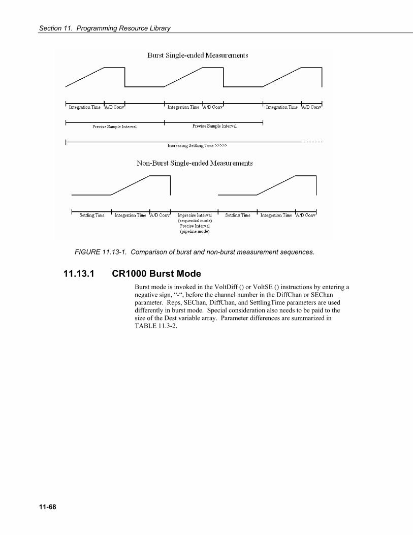
Section 11. Programming Resource Library
11-68
FIGURE 11.13-1. Comparison of burst and non-burst measurement sequences.
11.13.1 CR1000 Burst Mode Burst mode is invoked in the VoltDiff () or VoltSE () instructions by entering a negative sign, “-“, before the channel number in the DiffChan or SEChan parameter. Reps, SEChan, DiffChan, and SettlingTime parameters are used differently in burst mode. Special consideration also needs to be paid to the size of the Dest variable array. Parameter differences are summarized in TABLE 11.3-2.

Section 11. Programming Resource Library
11-69
TABLE 11.13-2. Burst Mode Parameter Changes for Burst Enabled Instructions
CRBASIC Parameter
Standard Analog Mode
Burst Analog Mode
Dest Var DIMed (1) to (16) Var DIMed (1) to (65535) Reps Sequential Channels Number of Measurements on single
channel (65535 Max) Range N/C N/C SEChan 1 to 16 -1 to -16 DiffChan 1 to 8 -1 to -8 RevDiff N/C N/C SettlingTime Settling Time Sample Interval (≥500 µs
minimum) Integ 250 µs, 50 / 60 Hz
rejection available. 50 / 60 Hz rejection available but not normally used.
Mult N/C N/C Offset N/C N/C
11.13.2 Comparing CR1000 and CR10X Burst Modes
Historical Note: Burst mode was invoked in older array based CSI dataloggers using Instruction 23 Burst Measurement.
CR1000 CR10X Channel sequence: 1, 1, 1…, 2, 2, 2…, 3, 3, 3…1
Channel sequence 1, 2, 3…, 1, 2, 3…, 1, 2, 3…2
2 kHz Max 750 Hz Max Data output only to resident memory Data to resident memory or out serial
port Raw A/D output not possible Raw A/D output possible Optional output to max 2G byte CF cards
Optional output to max 6M byte storage modules
Communications OK during burst No communications during burst Trigger using DataEvent() Trigger from P23 parameters All voltage ranges OK Only voltage ranges 25mV and greater
are practical 1A single VoltDiff or VoltSE instruction can burst on one channel only. To burst on multiple channels, multiple VoltDiff or VoltSE instruction are entered into the CRBASIC program. Burst on one channel completes before burst on the second channel begins. 2A single P23 instruction can burst on multiple channels, near simultaneously, by first measuring the channel programmed for first analog measurement, then the following channels sequentially, such that all channels complete at about the same time.

Section 11. Programming Resource Library
11-70
11.13.3 Burst Mode Programming Program EXAMPLE 11.13-1 shows a simple program burst measuring a single-ended thermocouple, 100 measurements at a 2 kHz rate. Data is logged to memory between when the variable Seconds equaling 28 and 35.
EXAMPLE 11.13-1. Burst Mode Programming
Public Seconds Public PanelT Public ThCSe(100) 'dimension variable for 100 measurements DataTable (TestSE,1,-1) DataEvent (0,Seconds=28,Seconds=35, 0) 'log data only between seconds 28 and 35, inclusive Sample (1,Seconds,FP2) Sample (1,PanelT,FP2) Sample (100,ThCSe(),FP2) EndTable BeginProg Scan (1,Sec,0,0) PanelTemp (PanelT,250) TCSe (ThCSe(),100,mV2_5,-1,TypeT,PanelT,False,500,250,1.0,0) '100 measurements at 2 kHz Seconds = Seconds + 1 CallTable TestSE NextScan EndProg
11.14 String Operations 11.14.1 Operators
String operators are sensitive to case.
Operator Description
& Concatenates strings. Forces numeric values to strings before concatenation. Example 1 & 2 & 3 & “a” & 5 & 6 & 7 = “123a567”
+ Adds numeric values until a string is encountered. When a string is encountered, it is appended to the sum of the numeric values. Subsequent numeric values are appended at strings. Example: 1 + 2 + 3 + “a” + 5 + 6 + 7 = “6a567”
- 1) “Subtracts” NULL ("") from the end of ASCII characters for conversion to an ASCII code (Long data type). Example “a” – "" = 97 2) ASCII codes of the first characters in each string are compared. If the difference between the codes is zero, codes for the next characters are compared. When unequal codes or NULL are encountered (NULL

Section 11. Programming Resource Library
11-71
terminates all strings), the difference between the last compared ASCII codes is returned. Examples: Since ASCII code for a = 97, b = 98, c = 99, d = 100, e = 101, and all strings end with NULL, “abc” – “abc” = 0 (difference between NULL and NULL) “abe” – “abc” = 2 (difference between e and c) “ace” – “abe” = 1 (difference between c and b) “abcd” – “abc” = 100 (difference between d and NULL)
<, >, <>, <=, >=, = ASCII codes of the first characters in each string are compared. If the difference between the codes is zero, codes for the next characters are compared. When unequal codes or NULL are encountered (NULL terminates all strings), the requested comparison is made. If the comparison is true, -1 or True is returned. If false, 0 or False is returned. Examples:
Expression Result x = “abc” = “abc” x = -1 or True x = “abe” = “abc” x = 0 or False x = “ace” > “abe” x = -1 or True
11.14.2 Concatenation Concatenation is the building of strings from other strings (“abc123”), characters (“a” or chr()), numbers, or variables.
Examples:
Expression Comments Result StringVar(1) = 5.4 + 3 + " Volts" Add Floats, Concatenate String “8.4 Volts” StringVar(2) = 5.4 & 3 & " Volts" Concatenate Floats and Strings “5.43 Volts” LongVar(1) = "123" Convert String to Long 123 LongVar (2) = 1+2+"3" Add Floats to String / convert to Long 33 LongVar (3) = "1"+2+3 Concatenate String and Floats 123 LongVar (4) = 1&2&"3" Concatenate Floats and String 123
11.14.3 NULL Character All strings are automatically NULL terminated. NULL, Chr(0) or "", counts as one of the characters in the string. Assignment of just one character is that character followed by a NULL, unless the character is a NULL.
Examples:
Expression Comments Result LongVar (5) = "#"-"" Subtract NULL, ASCII code results 35 LongVar (6) = StrComp("#","") Also subtracts NULL 35
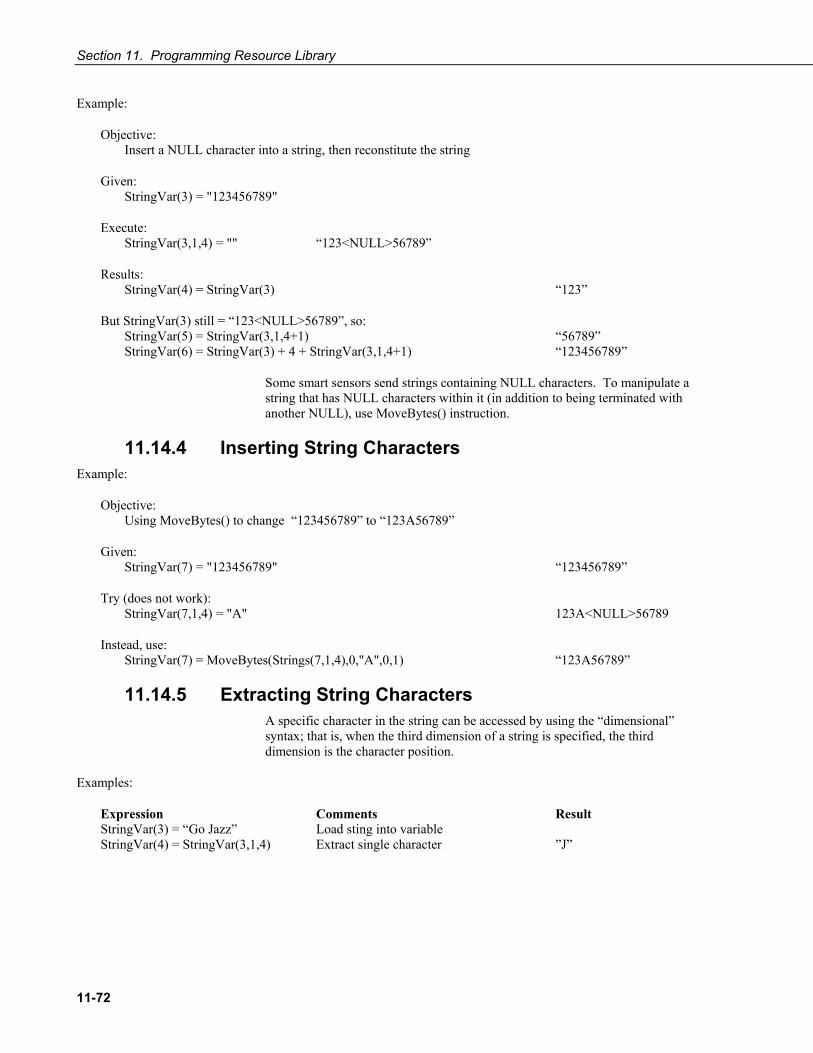
Section 11. Programming Resource Library
11-72
Example:
Objective: Insert a NULL character into a string, then reconstitute the string
Given: StringVar(3) = "123456789"
Execute: StringVar(3,1,4) = "" “123<NULL>56789”
Results: StringVar(4) = StringVar(3) “123”
But StringVar(3) still = “123<NULL>56789”, so: StringVar(5) = StringVar(3,1,4+1) “56789” StringVar(6) = StringVar(3) + 4 + StringVar(3,1,4+1) “123456789”
Some smart sensors send strings containing NULL characters. To manipulate a string that has NULL characters within it (in addition to being terminated with another NULL), use MoveBytes() instruction.
11.14.4 Inserting String Characters Example:
Objective: Using MoveBytes() to change “123456789” to “123A56789”
Given: StringVar(7) = "123456789" “123456789”
Try (does not work): StringVar(7,1,4) = "A" 123A<NULL>56789
Instead, use: StringVar(7) = MoveBytes(Strings(7,1,4),0,"A",0,1) “123A56789”
11.14.5 Extracting String Characters A specific character in the string can be accessed by using the “dimensional” syntax; that is, when the third dimension of a string is specified, the third dimension is the character position.
Examples:
Expression Comments Result StringVar(3) = “Go Jazz” Load sting into variable StringVar(4) = StringVar(3,1,4) Extract single character ”J”

Section 11. Programming Resource Library
11-73
11.14.6 Use of ASCII / ANSII Codes Examples:
Expression Comments Result LongVar (7) = ASCII("#") 35 LongVar (8) = ASCII("*") 42 LongVar (9) = "#" Cannot be converted to Long with NULL NAN LongVar (1) = "#"-"" Can be converted to Long without NULL 35
11.14.7 Formatting Strings Example:
Objective: Format the string “The battery is 12.4 Volts”
Use Expression: StringVar(11) = Mid("The battery is 12.4 Volts",InStr(1,"The battery is 12.4 Volts"," is ",2)+3,Len("The battery is 12.4 Volts"))
Result: 12.4 Volts
Examples:
Expression Result StringVar(1) = 123e4 1230000 StringVar(2) = FormatFloat(123e4,"%12.2f") 1230000.00 StringVar(3) = FormatFloat(Values(2)," The battery is %.3g Volts ") “The battery is 12.4 Volts” StringVar(4) = Strings(3,1,InStr(1,Strings(3),"The battery is ",4)) 12.4 Volts StringVar(5) = Strings(3,1,InStr(1,Strings(3),"is ",2) + 3) 12.4 Volts StringVar(6) = Replace("The battery is 12.4 Volts"," is "," = ") The battery = 12.4 Volts StringVar(7) = LTrim("The battery is 12.4 Volts") The battery is 12.4 Volts StringVar(8) = RTrim("The battery is 12.4 Volts") The battery is 12.4 Volts StringVar(9) = Trim("The battery is 12.4 Volts") The battery is 12.4 Volts StringVar(10) = UpperCase("The battery is 12.4 Volts") THE BATTERY IS 12.4 VOLTS StringVar(12) = Left("The battery is 12.4 Volts",7) The b StringVar(13) = Right("The battery is 12.4 Volts",7) Volts
11.14.8 Formatting Hexadecimal Variables Examples:
Expression Comment Result CRLFNumeric(1) = &H0d0a Add leading zero to hex step 1 3338 StringVar(20) = "0" & Hex(CRLFNumeric) Add leading zero to hex step 2 0D0A CRLFNumeric(2) = HexToDec(Strings(20)) Convert Hex string to Float 3338.00

Section 11. Programming Resource Library
11-74
11.15 Data Tables 11.15.1 Two Data Intervals – One Data Table
EXAMPLE 11.15-1. Programming for two data intervals in one data table
'CRBasic program To write To a single table with two different time intervals. 'Note: this Is a conditional table, check the Table Fill times in the Status Table. 'For programs with conditional tables AND other time driven tables it Is generally wise 'To NOT auto allocate the conditional table; set a specific number of records. 'date: February 2, 2006 'program author: Janet Albers 'Declare Public Variables Public PTemp, batt_volt, airtempC, deltaT Public int_fast As Boolean Public int_slow As Boolean Public counter(4) As Long 'Data Tables 'Table output on two intervals depending on condition. 'note the parenthesis around the TriggerVariable AND statements 'Status Table datafilldays field is low DataTable (TwoInt,(int_fast AND TimeIntoInterval (0,5,Sec)) OR (int_slow AND TimeIntoInterval (0,15,sec)),-1) Minimum (1,batt_volt,FP2,0,False) Sample (1,PTemp,FP2) Maximum (1,counter(1),Long,False,False) Minimum (1,counter(1),Long,False,False) Maximum (1,deltaT,FP2,False,False) Minimum (1,deltaT,FP2,False,False) Average (1,deltaT,IEEE4,false) EndTable 'Main Program BeginProg Scan (1,Sec,0,0) PanelTemp (PTemp,250) Battery (Batt_volt) counter(1)=counter(1)+1 'thermocouple measurement TCDiff (AirTempC,1,mV2_5C,1,TypeT,PTemp,True ,0,250,1.0,0) 'calculate the difference in air temperature and panel temperature deltaT=airtempC-PTemp 'when the the difference in air temperatures is >=3 turn LED on 'and trigger the data table's faster interval If deltaT>=3 Then PortSet (4,true) int_fast=true int_slow=false Else
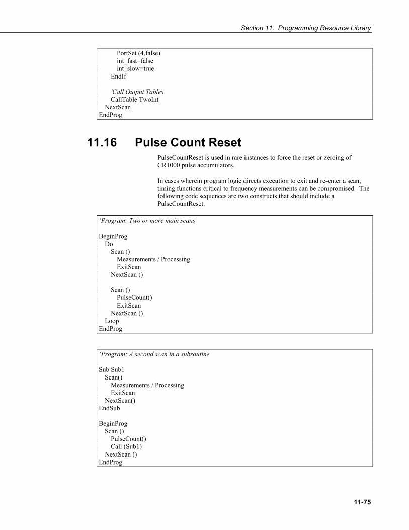
Section 11. Programming Resource Library
11-75
PortSet (4,false) int_fast=false int_slow=true EndIf 'Call Output Tables CallTable TwoInt NextScan EndProg
11.16 Pulse Count Reset PulseCountReset is used in rare instances to force the reset or zeroing of CR1000 pulse accumulators.
In cases wherein program logic directs execution to exit and re-enter a scan, timing functions critical to frequency measurements can be compromised. The following code sequences are two constructs that should include a PulseCountReset.
‘Program: Two or more main scans BeginProg Do Scan () Measurements / Processing ExitScan NextScan () Scan () PulseCount() ExitScan NextScan () Loop EndProg
‘Program: A second scan in a subroutine Sub Sub1 Scan() Measurements / Processing ExitScan NextScan() EndSub BeginProg Scan () PulseCount() Call (Sub1) NextScan () EndProg

Section 11. Programming Resource Library
11-76
PulseCountReset is recommended only when the program meets the following criteria.
a. Program logic exits the Scan () / NextScan construct wherein a PulseCount () instruction resides.
b. Pulse measurement is reported as a frequency or running average of frequency (pOption > 1).
c. Multiple Scan / NextScan instructions are used apart from SubScan or SlowSequence constructs.
When PulseCountReset is executed, the following occur.
a. Counts are discarded in all accumulators b. Previous value is retained when PulseCount is next executed. c. The third execution of PulseCount after execution of PulseCountReset
reports new data.
Programming Tip: When developing a program with PulseCountReset, output all measurements to a data table to allow examination of time stamps. By examining time stamps, the amount of data lost when using PulseCountReset can be evaluated.
11.16.1 PulseCountReset () Use Rules When using multiple main Scan () / NextScans, use PulseCountReset () prior to restarting the Scan() wherein PulseCount() resides, as shown in EXAMPLE 11.16-1.
EXAMPLE 11.16-1. Use of PulseCountReset with Multiple Main Scan() / NextScan
'Program to demonstrate the utility of PulseCountReset when multiple main scans are in the program. 'Counters [cnt(1) & cnt(2)] are used only to show Scan() / NextScan activity during demonstration. 'To begin the demonstration, manually toggle CountScanFlag True, then False. Public PulseHz Public Cnt(2) Public CountScanFlag As Boolean DataTable (HzData,True,-1) 'Data output to observe time stamps / missing data Sample (1,PulseHz,IEEE4) EndTable BeginProg Do Scan(1,Sec,0,0) 'Use Scan() count, or use ExitScan in or out of conditional Cnt(1) = Cnt(1) + 1 If CountScanFlag = false Then ExitScan NextScan PulseHz = 0 'Zero PulseHz, otherwise last measurement used (Optional) PulseCountReset 'PulseCountReset prior to restarting Scan() wherein PulseCount resides

Section 11. Programming Resource Library
11-77
Scan (1,Sec,0,0) PulseCount (PulseHz,1,1,0,10000,1.0,0) Cnt(2) = Cnt(2) + 1 CallTable HzData If CountScanFlag = True Then ExitScan NextScan Loop EndProg
If the program contains a subroutine that includes a second Scan() / NextScan, as demonstrated in EXAMPLE 11.16-2, observe the following rules:
a. Place subroutine call in a conditional statement to allow a valid pulse measurement to be made.
b. Place PulseCountReset () in a conditional statement prior to PulseCount () in the main scan.
c. Call the subroutine after PulseCount (). d. Call data tables that store results from PulseCount () prior to the
subroutine call.
EXAMPLE 11.16-2. Use of PulseCountReset with Secondary Scan() / NextScan in a Subroutine
'Program to demonstrate the utility of PulseCountReset when a subroutine with a Scan / NextScan is called. 'Counters [cnt(1) & cnt(2)] are used only to show Scan() / NextScan activity during demonstration. 'To begin the demonstration, manually toggle CountScanFlag True, then False. Public PulseHz Public Cnt(2) Public CallSub1 As Boolean Public PulseCountResetControl As Boolean DataTable (HzData,True,-1) 'Data output to observe time stamps / missing data Sample (1,PulseHz,IEEE4) EndTable Sub Sub1 Scan(1,Sec,0,0) 'Use Scan() count, or use ExitScan in or out of conditional Cnt(1) = Cnt(1) + 1 If CallSub1 = False Then ExitScan NextScan PulseCountResetControl = True PulseHz = 0 'Zero PulseHz, otherwise last measurement used (Optional) EndSub BeginProg Scan (1,Sec,0,0) If PulseCountResetControl = True Then PulseCountReset 'PulseCountReset in a conditional construct prior to PulseCount PulseCountResetControl = False EndIf

Section 11. Programming Resource Library
11-78
PulseCount (PulseHz,1,1,0,10000,1.0,0) Cnt(2) = Cnt(2) + 1 CallTable HzData 'Data table call prior to subroutine call If CallSub1 = True Then Call (Sub1) 'Subroutine call after PulseCount NextScan EndProg
Note that frequency running averaging (pOption > 1) is most susceptible to the problems of exiting scans, showing a significant deviation in Examples 11.16-1 and 11.16-2 if PulseCountReset is removed, regardless of scan interval used. Measurement of simple frequency is less susceptible because an internal timing feature tracks frequency timing. However, this feature is compromised when scan intervals greater than 2796 seconds (24 bit accumulator * 10 ms clock tick) are used. Care should be taken if using PulseCountReset when total counts are desired. PulseCountReset may cause counts to be discarded before they are stored in a data table.

12-1
Section 12. Memory and Data Storage 12.1 Storage Media
CR1000 memory consists of four non-volatile storage media:
1. Battery Backed SRAM 2. Flash Memory 3. Serial Flash Memory 4. CompactFlash® Memory (optional)
Tables 12-1and 12-2 illustrate how CR1000 memory is structured around these media. The CR1000 utilizes and maintains most memory features automatically. However, users should periodically review areas of memory wherein data files, CRBASIC program files, and image files reside. Review and management of memory are accomplished with LoggerNet / PC400 / RTDAQ / PC200W File Control.

Section 12. Memory and Data Storage
12-2
TABLE 12-1. CR1000 Memory Allocation
NOTE: Prior to September 2007, CR1000s were shipped with 2MB SRAM. Additional 2MB was optional. From September 2007, all CR1000s are shipped with 4 MB SRAM.
SRAM 4 Mbytes:
Device Settings
≈ 12 Kbyte
CPU: Drive
≈ 500 Kbytes
Serial Flash 512 Kbytes:
See Table 12-2 for a detailed breakdown. Operating system. A backup of device settings, such as PakBus Address, Station Name, Beacon Intervals, Neighbor lists, etc. Rebuilt when a setting changes. Holds program files, field calibration files, and other files not over written frequently. Slower than SRAM. When a program is compiled and run, it is copied here automatically for loading on subsequent power-ups. Files accumulate until deleted with File Control or the FilesManage () instruction. Use USR: drive to store other file types. Available CPU: memory is reported in Status Table field “CPUDriveFree.” See Appendix F.14 for available CompactFlash® devices. Holds program files. Holds final storage table data as files when CardOut () instruction is used. When data are requested by a PC, data first are provided from SRAM. If the requested records have been overwritten in SRAM, data are sent from CRD:. Alternatively, CRD: data can be retrieved in a binary format using File Control. Binary files are converted using CardConvert software.
Notes
Optional CompactFlash®:
CRD: Drive Size: ≤ 2 Gbytes
Flash 2 Mbytes:
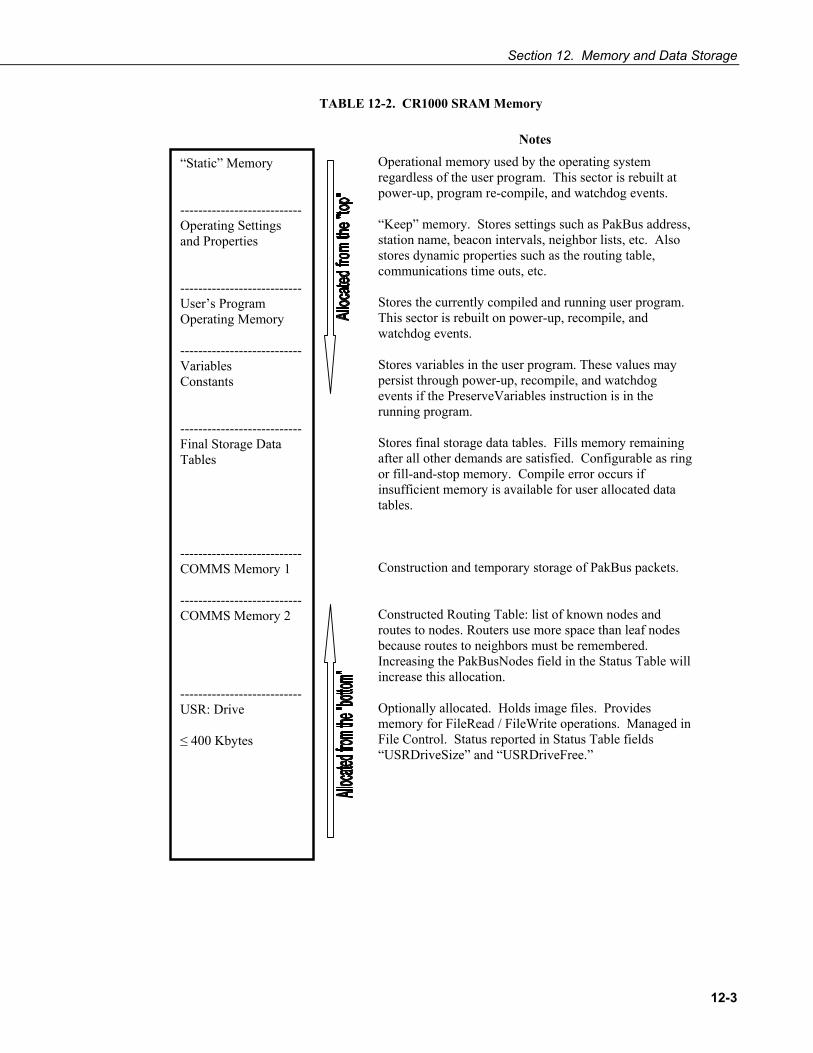
Section 12. Memory and Data Storage
12-3
TABLE 12-2. CR1000 SRAM Memory
“Static” Memory --------------------------- Operating Settings and Properties --------------------------- User’s Program Operating Memory --------------------------- Variables Constants --------------------------- Final Storage Data Tables --------------------------- COMMS Memory 1 --------------------------- COMMS Memory 2 --------------------------- USR: Drive ≤ 400 Kbytes
Operational memory used by the operating system regardless of the user program. This sector is rebuilt at power-up, program re-compile, and watchdog events. “Keep” memory. Stores settings such as PakBus address, station name, beacon intervals, neighbor lists, etc. Also stores dynamic properties such as the routing table, communications time outs, etc. Stores the currently compiled and running user program. This sector is rebuilt on power-up, recompile, and watchdog events. Stores variables in the user program. These values may persist through power-up, recompile, and watchdog events if the PreserveVariables instruction is in the running program. Stores final storage data tables. Fills memory remaining after all other demands are satisfied. Configurable as ring or fill-and-stop memory. Compile error occurs if insufficient memory is available for user allocated data tables. Construction and temporary storage of PakBus packets. Constructed Routing Table: list of known nodes and routes to nodes. Routers use more space than leaf nodes because routes to neighbors must be remembered. Increasing the PakBusNodes field in the Status Table will increase this allocation. Optionally allocated. Holds image files. Provides memory for FileRead / FileWrite operations. Managed in File Control. Status reported in Status Table fields “USRDriveSize” and “USRDriveFree.”
Notes
Section 12. Memory and Data Storage
12-4
12.2 Data Storage The CR1000 can be programmed to store each measurement or, more commonly, to store processed values such as averages, maxima, minima, histograms, FFTs, etc. Data are stored periodically or conditionally in data tables as directed by the CRBASIC program (Section 9.5 Structure). The DataTable () instruction allows the user to set the size of the data table. Four areas are partitioned in the storage media for data storage: Data table SRAM, CPU: drive, USR: drive, and CRD: drive.
12.2.1 Data Table SRAM Primary storage for numeric data are those areas in SRAM allocated to data tables as detailed in Table 12.1-2. Data are usually erased from this area when a program is sent to the CR1000. However, options are available in LoggerNet / PC400 / RTDAQ / PC200W File Control and CRBASIC Editor to preserve data when downloading programs.
12.2.2 CPU: Drive CPU: is the default drive to which programs and calibration files are stored. Do not store data on CPU:.
12.2.3 USR: Drive SRAM can be partitioned to create a FAT32 USR: drive, analogous to partitioning a second drive on a PC hard disk. Certain types of files are stored to USR: to reserve limited CPU: memory for datalogger programs and calibration files. Partitioning also helps prevent interference from data table SRAM. USR: is configured using DevConfig settings or SetStatus () instruction in a CRBASIC program. Partition USR: drive to at least 11264 bytes in 512 byte increments. If the value entered is not a multiple of 512 bytes, the size is rounded up. Maximum size of USR: is 400 kbytes.
USR: is not affected by program recompilation or formatting of other drives. It will only be reset if the USR: drive is formatted, a new operating system is loaded, or the size of USR: is changed. USR: size is changed manually using the datalogger keyboard or by loading a program with a different size entered in a SetStatus () command.
Placing an optional USR: size setting in the user program over-rides manual changes to USR: size. When USR: size is changed manually, the user program restarts and the programmed size for USR: takes immediate effect.
The USR: drive holds any file type within the constraints of the size of the drive and the limitations on filenames. Files typically stored include image files from cameras (see Appendix F.15 for camera information), certain configuration files, files written for ftp retrieval, and html files for viewing via web access. Files can be collected by ftp using LoggerNet / PC400 / RTDAQ / PC200W File Control, or automatically using the LNCMD program supplied exclusively with LoggerNet.
NOTE

Section 12. Memory and Data Storage
12-5
Monitor use of available USR: memory to ensure adequate space to store new files. FileManage () command is used within the CR1000 user program to remove files. Files also can be removed using LoggerNet / PC400 / RTDAQ / PC200W File Control.
Two status table registers monitor use and size of the USR: drive. Bytes remaining are indicated in register “USRDriveFree.” Total size is indicated in register “USRDriveSize.” Memory allocated to USR: drive, less overhead for directory use, is shown in LoggerNet / PC400 / RTDAQ / PC200W File Control.
12.2.4 CRD: Drive CRD: drive uses CompactFlash® memory exclusively. Its primary purpose is the storage of binary data files.
When installing or removing card storage modules, first turn off CR1000 power.
Removing a card from the module while the CF card is active can cause data corruption and may damage the card. Always press the removal button to disable the card and wait for the green LED before removing the card or switching off power prior to removal of the card.
To prevent losing data, collect data from the CF card before sending a program to the datalogger. When a program is sent to the datalogger all data on the CF card may be erased.
CSI CF card modules connect to the CR1000 peripheral port. Each has a slot for Type I or Type II CF cards. A maximum of 30 data tables can be created on a CF card. Refer to Appendix F.14 for information on available CF card modules.
CardConvert software, included with LoggerNet / PC400 / , RTDAQ / PC200W support software, converts binary card data to the standard Campbell Scientific data format.
When a data table is sent to a CF card, a data table of the same name in SRAM is used as a buffer for transferring data to the card. When the card is present, the status table will show the size of the table on the card. If the card is removed, the size of the table in SRAM is shown.
When a new program is compiled that sends data to the CF card, the CR1000 checks if a card is present and if the card has adequate space for the data tables. If no card is present, or if space is inadequate, the CR1000 will warn that the card is not being used. However, the user program is run and data stored to SRAM. When a card is later inserted, accumulated data is copied to the card.
The CR1000 accepts cards formatted as FAT or FAT32; however, FAT32 is recommended. Otherwise, some functionality, such as the ability to manage large numbers of files (>254) is lost. Older CR1000 operating systems
CAUTION
NOTE

Section 12. Memory and Data Storage
12-6
formatted cards as FAT or FAT32. Newer operating systems always format cards as FAT32.
12.3 Memory Conservation One or more of the following memory saving techniques can be used on the rare occasions when a program reaches memory limits:
• Declare variables as DIM instead of Public. DIM variables do not require buffer memory for data retrieval.
• Reduce arrays to the minimum size needed. Each variable, whether or not part of an array, requires about the same amount of memory. Approximately 720 variables will fill available memory.
• Use variable arrays with aliases instead of individual variables with unique names. Aliases consume less memory than unique variable names.
• Confine string concatenation to DIM variables.
• Dimension string variables only to the size required.
Read More! More information on string variable memory use and conservation is available in Section 11.14 String Operations.
12.4 Memory Reset Four features are available for complete or selective reset of CR1000 memory.
12.4.1 Full Memory Reset Full memory reset occurs when an operating system is sent to the CR1000 using DevConfig or when entering “98765” in the status table field “FullMemReset.” A full memory reset does the following:
o Clears and Formats CPU: drive (all program files erased) o Clears SRAM data tables o Clears Status Table Elements o Restores settings to default o Initializes system variables o Clears communications memory
Full memory reset does not affect the CRD: drive directly. Subsequent user program uploads, however, can affect CRD:.
Operating systems can also be sent using the Program Send feature in LoggerNet / PC400 / RTDAQ / PC200W. Beginning with operating system version 16, settings and status is preserved when sending a subsequent OS by this method. Data tables is erased. Rely on this feature with caution, however, when sending an OS to dataloggers in remote and difficult to access areas.

Section 12. Memory and Data Storage
12-7
12.4.2 Program Send Reset All SRAM and CRD: data are erased when user programs are uploaded, unless preserve / erase data options are used. Preserve / erase data options are presented when sending programs from LoggerNet / PC400 / RTDAQ / PC200W File Control and CRBASIC Editor Compile / Save / Send. See Section 9.2.1 a more detailed discussion of preserve / erase data at program send options.
12.4.3 Manual Data Table Reset Data table memory is selectively reset from
• LoggerNet / PC400 / RTDAQ / PC200W | Datalogger | Station Status • Keyboard / Display Data | Reset Data Tables
12.4.4 Formatting Drives CPU:, USR:, and CRD: drives can be formatted individually. Formatting a drive erases all files on that drive. If the currently running user program is found on the drive to be formatted, the program will cease running and any SRAM data associated with the program is erased. Drive formatting is performed through LoggerNet / PC400 / RTDAQ / PC200W File Control.
12.5 File Management Files in CR1000 memory (program, data, CAL, image) can be managed or controlled with Campbell Scientific support software as summarized in TABLE 12.5-1.

Section 12. Memory and Data Storage
12-8
TABLE 12.5-1. File Control Functions
File Control Functions Accessed Through
Sending programs to the CR1000.
Send1, File Control2, DevConfig3, keyboard with CF card4, power-up with CF card5
Setting file attributes. See TABLE 12.5-2.
File Control2, power-up with CF card5, FileManage () instruction6.
Sending an OS to the CR1000. Reset settings.
File Control2, DevConfig3, automatic with CF card5
Sending an OS to the CR1000. Preserve settings.
Send1, File Control with default.cr12, power-up with CF card with default.cr1 file5
Formatting CR1000 memory drives.
File Control2, power-up with CF card5.
Retrieving programs from the CR1000.
Connect7, File Control2, keyboard with CF card4
Setting disposition of old CF files
File Control2, power-up with CF card5.
Deleting files from memory drives.
File Control2, power-up with CF card5.
Stopping program execution. File Control2.
Renaming a file. FileRename ()6
Time stamping a file. FileTime ()6
List files. File Control2, FileList ()6
Create a data file from a data table
TableFile ()6
JPEG files manager CR1000KD, LoggerNet | PakBusGraph
1LoggerNet / PC400 / RTDAQ / PC200W Program Send Button. See software Help.
2LoggerNet / PC400 / RTDAQ / PC200W File Control. See software Help.
3Device Configuration Utility (DevConfig). See DevConfig Help.
4Manual with CompactFlash®. See Section 12.2.
5Automatic with CompactFlash® and Powerup.ini. See Section 12.5.3.
6CRBASIC commands. See Sections 10.2.2 and 10.14 and CRBASIC Editor Help.
7LoggerNet / PC400 / RTDAQ / PC200W program Retrieve button. See software Help.

Section 12. Memory and Data Storage
12-9
12.5.1 File Attributes A feature of program files is the file attribute. TABLE 12.5-2 lists available file attributes, their functions, and when attributes are typically used. For example, a program file sent via the Send option in LoggerNet / PC400 / RTDAQ / PC200W, runs a) immediately (“Run Now”) and b) when power is cycled on the CR1000 (“Run on Power-up). This functionality is invoked because Send sets two CR1000 file attributes on the program file, i.e., “Run Now” and “Run on Power-up.” When together, “Run Now” and “Run on Power-up” are tagged as “Run Always.”
Activation of the Run on Power-up file can be prevented by holding down the Del key on the keyboard / display while the CR1000 is being powered up.
TABLE 12.5-2. CR1000 File Attributes
Attribute
Function
Attribute for Programs Sent to CR1000 with:
Run Always (Run on Power-up + Run Now)
Runs now and on power-up
a) Send1 b) File Control2 with Run Now & Run on Power-up checked. c) CF power-up3 using commands 1 & 13 (see TABLE 12.5-3).
Run on Power-up
Runs only on power-up
a) File Control2 with Run on Power-up checked. b) CF power-up3 using command 2 (see TABLE 12.5-3).
Run Now Runs only when file sent to CR1000
a) File Control2 with Run Now checked. b) CF power-up3 using commands 6 & 14 (see TABLE 12.5-3). But, if CF is left in, program loads again from CF.
1LoggerNet / PC400 / RTDAQ / PC200W Program Send Button. See software Help.
2LoggerNet / PC400 / RTDAQ / PC200W | Datalogger | File Control. See software Help & Section 9.2.1.
3Automatic on power-up of CR1000 with CompactFlash® and Powerup.ini. See Section 12.5.3.
12.5.2 Data Preservation Associated with file attributes is the option to preserve data in CR1000 memory when a program is sent. This option applies to CPU, CompactFlash®, and software cache data. Depending on the application, retention of data files when a program is downloaded may be desirable. When sending a program
NOTE

Section 12. Memory and Data Storage
12-10
with LoggerNet / PC400 / RTDAQ / PC200W Send, data are always deleted before the program runs. When the program is sent using File Control or CRBASIC Editor “Compile, Save, and Send,” options to preserve (do not erase) or not preserve (erase) data are presented. The logic in FIGURE 12.5-1 summarizes the disposition of CR1000 data depending on the data preservation option selected.
if “Preserve data if no table changed” keep CF data from overwritten program if current program = overwritten program keep CPU data keep cache data else erase CPU data erase cache data end if end if if “erase CF data” erase CF data from overwritten program erase CPU data erase cache data end if
FIGURE 12.5-1. Summary of the Effect of CF Data Options on CR1000 Data.
12.5.3 CF Power-up Hard Knocks in a Real World
Uploading an OS or program in the field can be challenging, particularly during weather extremes. Heat, cold, snow, rain, altitude, sand in your eyes, distance to hike – all can influence how easily programming with a laptop or palm PC may be. One alternative is to simply carry a light weight CF card into the field, on which a program or OS is written. Inserting a properly configured CF card into a CR1000 CF module (Appendix F.14),then cycling CR1000 power, will result in the OS or program automatically uploading and running without further input from the user. OS upload from a CF card is very fast. CAUTION. Test this option in the lab before going to the field to make sure you have it configured correctly. Carry your laptop or palm PC with you, but with CF Power-up, you will be overjoyed when you don’t need to pull the computer out.
Power-up functions of CompactFlash® cards can include
a) Sending programs to the CR1000 b) Setting attributes of CR1000 program files c) Setting disposition of old CF files d) Sending an OS to the CR1000 e) Formatting memory drives f) Deleting data files
Section 12. Memory and Data Storage
12-11
“Oh, what a tangled web we weave...” – Sir Walter Scott.
Back in the old days of volatile RAM, life was simple. Lost power meant lost programs, variables, and data. The advent of non-volatile memory has saved a lot of frustration in the field, but it requires thought in some applications. For instance, if the CR1000 loses power, do you want it to power back up with the same program, or another one? with variables intact or erased? with data intact or erased?
The key to the CF power-up function is the powerup.ini file, which contains a list of one or more command lines. At power-up, the powerup.ini command line is executed prior to compiling the program. Powerup.ini performs three operations:
1) Copies the specified program file to a specified memory drive.
2) Sets a file attribute on the program file
3) Optionally deletes CF data files from the overwritten (just previous) program.
Powerup.ini takes precedence during power-up. Though it sets file attributes for the programs it uploads, its presence on the CF does not allow those file attributes to control the power-up process. To avoid confusion, either remove the CF card or delete the powerup.ini file after the powerup.ini upload.
Creating and Editing Powerup.ini
Powerup.ini is created with a text editor, then saved as “powerup.ini”.
Some text editors (such as WordPad) will attach header information to the powerup.ini file causing it to abort. Check the text of a powerup.ini file with the CR1000KD to see what the CR1000 actually sees.
Comments can be added to the file by preceding them with a single-quote character (‘). All text after the comment mark on the same line is ignored.
Syntax Powerup.ini syntax allows data table erase / preserve functionality comparable to LoggerNet / PC400 / RTDAQ / PC200W File Control. Powerup.ini is a text file that contains a list of commands and parameters. The syntax for the file is:
Command,File,Device
where
Command = one of the numeric commands in Table 1. File = file on CF associated with the action. Name can be up to 22
characters. Device = the device to which the associated file is copied to. Options are
CPU:, USR:, and CRD:. If left blank or with invalid option, will default to CPU:.
NOTE
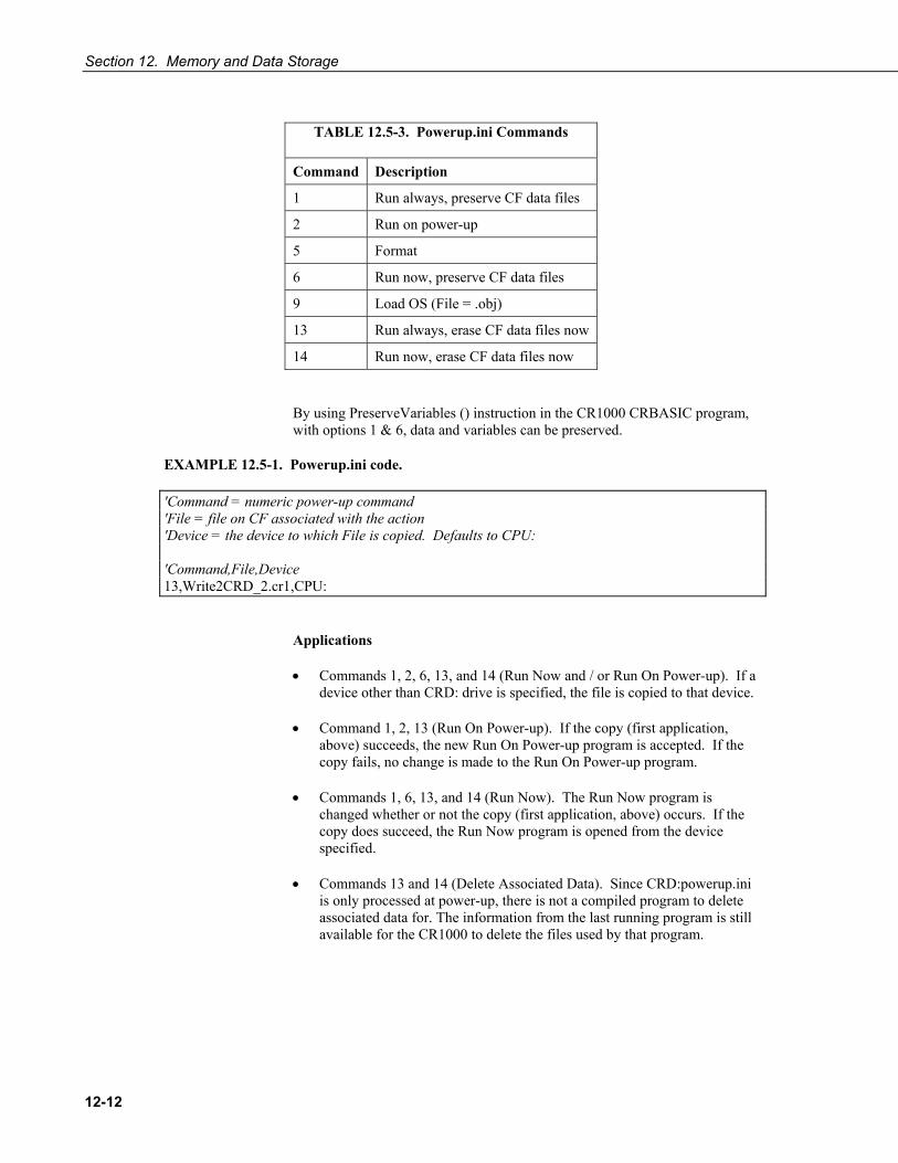
Section 12. Memory and Data Storage
12-12
TABLE 12.5-3. Powerup.ini Commands
Command Description
1 Run always, preserve CF data files
2 Run on power-up
5 Format
6 Run now, preserve CF data files
9 Load OS (File = .obj)
13 Run always, erase CF data files now
14 Run now, erase CF data files now
By using PreserveVariables () instruction in the CR1000 CRBASIC program, with options 1 & 6, data and variables can be preserved.
EXAMPLE 12.5-1. Powerup.ini code.
'Command = numeric power-up command 'File = file on CF associated with the action 'Device = the device to which File is copied. Defaults to CPU: 'Command,File,Device 13,Write2CRD_2.cr1,CPU:
Applications
• Commands 1, 2, 6, 13, and 14 (Run Now and / or Run On Power-up). If a device other than CRD: drive is specified, the file is copied to that device.
• Command 1, 2, 13 (Run On Power-up). If the copy (first application, above) succeeds, the new Run On Power-up program is accepted. If the copy fails, no change is made to the Run On Power-up program.
• Commands 1, 6, 13, and 14 (Run Now). The Run Now program is changed whether or not the copy (first application, above) occurs. If the copy does succeed, the Run Now program is opened from the device specified.
• Commands 13 and 14 (Delete Associated Data). Since CRD:powerup.ini is only processed at power-up, there is not a compiled program to delete associated data for. The information from the last running program is still available for the CR1000 to delete the files used by that program.

Section 12. Memory and Data Storage
12-13
Program Execution
After File is processed, the following rules determine what CR1000 program to run:
1) If the Run Now program is changed then it is the program that runs. 2) If no change is made to Run Now program, but Run on Power-up program
is changed, the new Run on Power-up program runs. 3) If neither Run on Power-up nor Run Now programs are changed, the
previous Run on Power-up program runs.
Example Power-up.ini Files
EXAMPLE 12.5-2 through EXAMPLE 12.5-7 are example powerup.ini files.
EXAMPLE 12.5-2. Run Program on Power-up.
’Copy pwrup.cr1 to USR:, will run only when powered-up later 2,pwrup.cr1,usr:
EXAMPLE 12.5-3. Format the USR: drive.
’Format the USR: drive 5,,usr:
EXAMPLE 12.5-4. Send OS on Power-up.
’Load this file into FLASH as the new OS 9,CR1000.Std.04.obj
EXAMPLE 12.5-5. Run Program from CRD: drive.
’Leave program on CRD:, run always, erase CRD: data files 13,toobigforcpu.cr1,crd:
EXAMPLE 12.5-6. Run Program Always, Erase CF data.
’Run always, erase CRD: data files 13,pwrup_1.cr1,crd
EXAMPLE 12.5-7. Run Program Now, Erase CF data.
’Copy run.cr1 to CPU:, erase CF data, run CPU:run.cr1, but not if later powered-up 14,run.cr1,cpu:

Section 12. Memory and Data Storage
12-14
12.6 File Names The maximum size of the file name that can be stored, run as a program, or FTP transferred in the CR1000 is 59 characters. If the name is longer than 59 characters an "Invalid Filename" error is displayed. If several files are stored, each with a long filename, memory allocated to the root directory can be exceeded before the actual memory of storing files is exceeded. When this occurs, an “insufficient resources or memory full” error is displayed.

13-1
Section 13. Telecommunications and Data Retrieval
Telecommunications, in the context of CR1000 operation, is the movement of information between the CR1000 and another computing device, usually a PC. The information can be programs, data, files, or control commands.
Telecommunications systems require three principal components: hardware, carrier signal, and protocol. For example, a common way to communicate with the CR1000 is with PC200W software by way of a PC COM port. In this example, hardware are the PC COM port, the CR1000 RS-232 port, and a serial cable. The carrier signal is RS-232, and the protocol is PakBus. Of these three, a user most often must come to terms with only the hardware, since the carrier signal and protocol are transparent in most applications.
Systems usually require a single type of hardware and carrier signal. Some applications, however, require hybrid systems, which utilize two or more hardware and signal carriers.
Contact a Campbell Scientific applications engineer for assistance in configuring any telecommunications system.
13.1 Hardware and Carrier Signal Campbell Scientific supplies or recommends a wide range of telecommunications hardware. TABLE 13.1-1 lists telecommunications destination, device, path, and carrier options which imply certain types of hardware for use with the CR1000 datalogger. Information in TABLE 13.1-1 is generic. For specific model numbers and specifications, see Appendix F.12.2, contact a Campbell Scientific applications engineer, or go to www.campbellsci.com.
TABLE 13.1-1. CR1000 Telecommunications Options
Destination Device / Portal Communications Path Carrier Signal
PC / COM or USB Direct Connect RS-232 PDA / COM Port Direct Connect RS-232 PC / COM Port Digital Cellular 800 MHz RF PC / COM Port Multidrop RS485 PC / Network Card Ethernet / PPP IP PC / COM Port Spread Spectrum RF 900 MHz RF PC / COM Port Licensed Frequency RF UHF VHF RF PC / COM Port Short-haul Telephone CCITT v.24 PC / COM Port Land-line Telephone CCITT v.92 PDA / Infrared Port Infrared SIR Satellite System Satellite Transceiver RF CompactFlash Card Direct Connect SRAM Audible Report Land-line Telephone Voice Heads-Up Display Direct Connect CS I/O Digital Display Direct Connect CS I/O Keyboard / Display Direct Connect CS I/O

Section 13. Telecommunications and Data Retrieval
13-2
13.2 Protocols The primary telecommunication protocol for the CR1000 is PakBus (Section 14 PakBus Overview). ModBus and DNP3 are also supported on board (Section 15). CANBUS is also supported when using the Campbell Scientific CANBUS communications module.
13.3 Initiating Telecommunications Telecommunications sessions are usually initiated by a PC. Once telecommunication is established, the PC issues commands to send programs, set clocks, collect data, etc. Because data retrieval is managed by the PC, several PC’s can have access to a CR1000 without disrupting the continuity of data. PakBus allows multiple PCs to communicate with the CR1000 simultaneously when proper telecommunications networks are installed.
When using RTDAQ / PC400 / PC200W software, the PC initiates telecommunications. LoggerNet software typically initiates telecommunications as well; however, some applications require the CR1000 to initiate telecommunications. This feature is called Callback. Special features in LoggerNet enable the PC to receive calls from the CR1000.
For example, if a fruit grower wants the CR1000 to contact him with a frost alarm, it can call the grower’s PC, send him an email, text message, or page, or call him with synthesized voice over telephone. Callback has been utilized in applications including Ethernet, land-line telephone, digital cellular, and direct connection. Callback via telephone is well documented in CRBASIC Editor Help. For more information on other available Callback features, manuals for various telecommunications hardware may discuss Callback options. Contact a Campbell Scientific applications engineer for the latest information in Callback applications.
When using the ComME communications port with non-PakBus protocols, incoming characters can be corrupted by concurrent use of the CS I/O for SDC communication. PakBus communication uses a low level protocol of a pause / finish / ready sequence to stop incoming data while SDC occurs.
Non-PakBus communication includes PPP protocol, ModBus, DNP3, and generic CRBASIC driven use of CS I/O.
Usually unnoticed, a short burst of SDC communication occurs at power up and other times when the datalogger is reset, such as when compiling a program or changing settings that require recompiling. This SDC activity is the datalogger querying the SDC to see if the CR1000KD Keyboard / Display, an SDC device, is attached.
When DevConfig and PakBus Graph retrieve settings, the CR1000 queries the SDC to determine what SDC devices are connected. Results of the query can be seen in the DevConfig and PakBus Graph settings tables. SDC queries occur whether or not an SDC device is attached.
CAUTION
Section 13. Telecommunications and Data Retrieval
13-3
13.4 Data Retrieval Data tables are transferred to PC files through a telecommunications link (Section 13 Telecommunications and Data Retrieval) or by transporting the CF card to the PC.
13.4.1 Via Telecommunications Data are usually transferred through a telecommunications link to an ASCII file on the supporting PC using Campbell Scientific datalogger support software (Section 16 Support Software). See also the manual and Help for the software package being used.
13.4.2 Via CF Card When installing a CF card module, first turn off the CR1000 power.
Before removing a CF card module from the datalogger, disable the card by pressing the “removal button” (NOT the eject button), wait for the green LED, then turn the CR1000 power off.
Removing a card or card module from the CR1000 while the CF card is active can cause garbled data and can damage the card.
Sending a program to the CR1000 may erase all SRAM and CF card data. To prevent losing data, collect data from the CF card before sending a program to the datalogger.
Data stored on CF cards are retrieved through a telecommunication link to the CR1000 or by removing the card and carrying it to a computer. Many varieties of CF adapters are available for computers and PCMCIA card slots. CF adaptors are much faster than telecommunications links, so, with large CF files, transferring data to a computer with an adaptor is significantly faster.
The format of data files collected via a CF adaptor is different than the format created by Campbell Scientific telecommunications software. Data files read from the CF card via a CF adaptor can be converted to a Campbell Scientific format using CardConvert. CardConvert is included with most CSI software. Consult the software manual for more CardConvert information.
13.4.3 Data Format on Computer CR1000 data stored on a PC via support software is formatted as either ASCII or Binary depending on the file type selected in the support software. Consult the software manual for details on the various available data file formats.
CAUTION

Section 13. Telecommunications and Data Retrieval
13-4
This is a blank page.

14-1
Section 14. PakBus Overview Read More! This section is provided as a primer to PakBus communications. Complete information is available in Campbell Scientific’s “PakBus Networking Guide.”
The CR1000 communicates with computers or other dataloggers via PakBus. PakBus is a proprietary telecommunications protocol similar in concept to IP (Internet protocol). PakBus allows compatible Campbell Scientific dataloggers and telecommunications hardware to seamlessly link to a PakBus network.
14.1 PakBus Addresses CR1000s are assigned PakBus address 1 as a factory default. Networks with more than a few stations should be organized with an addressing scheme that guarantees unique addresses for all nodes. One approach, demonstrated in Fig. 1, is to assign single-digit addresses to the first tier of nodes, multiples of tens to the second tier, multiples of 100s to the third, etc. Note that each node on a branch starts with the same digit. Devices, such as PCs, with addresses greater than 4000 are given special administrative access to the network
PakBus addresses are set using DevConfig, PakBusGraph, CR1000 status table, or with a CR1000KD Keyboard Display. DevConfig (Device Configuration Utility) is the primary settings editor for Campbell Scientific equipment. It requires a hardwire RS-232 connection to a PC and allows backup of settings on the PC hard drive. PakBusGraph is used over a telecommunications link to change settings, but has no provision for backup.
Caution. Care should be taken when changing PakBus addresses with PakBus Graph or in the status table. If an address is changed to an unknown value, a field visit with a laptop and DevConfig may be required to discover the unknown address.
14.2 Nodes: Leaf Nodes and Routers • A PakBus network consists of 2 to 4093 linked nodes.
• One or more leaf nodes and routers can exist in a network.
• Leaf nodes are measurement devices at the end of a branch of the PakBus web.
o Leaf nodes can be linked to any router.
o A leaf node cannot route packets but can originate or receive them.
• Routers are measurement or telecommunications devices that route packets to other linked routers or leaf nodes.
o Routers can be branch routers. Branch routers only know as neighbors central routers, routers in route to central routers, and routers one level outward in the network.
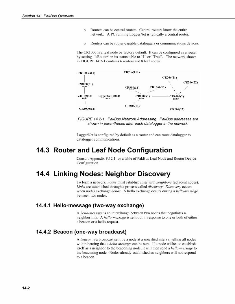
Section 14. PakBus Overview
14-2
o Routers can be central routers. Central routers know the entire network. A PC running LoggerNet is typically a central router.
o Routers can be router-capable dataloggers or communications devices.
The CR1000 is a leaf node by factory default. It can be configured as a router by setting “IsRouter” in its status table to “1” or “True”. The network shown in FIGURE 14.2-1 contains 6 routers and 8 leaf nodes.
FIGURE 14.2-1. PakBus Network Addressing. PakBus addresses are shown in parentheses after each datalogger in the network.
LoggerNet is configured by default as a router and can route datalogger to datalogger communications.
14.3 Router and Leaf Node Configuration Consult Appendix F.12.1 for a table of PakBus Leaf Node and Router Device Configuration.
14.4 Linking Nodes: Neighbor Discovery To form a network, nodes must establish links with neighbors (adjacent nodes). Links are established through a process called discovery. Discovery occurs when nodes exchange hellos. A hello exchange occurs during a hello-message between two nodes.
14.4.1 Hello-message (two-way exchange) A hello-message is an interchange between two nodes that negotiates a neighbor link. A hello-message is sent out in response to one or both of either a beacon or a hello-request.
14.4.2 Beacon (one-way broadcast) A beacon is a broadcast sent by a node at a specified interval telling all nodes within hearing that a hello-message can be sent. If a node wishes to establish itself as a neighbor to the beaconing node, it will then send a hello-message to the beaconing node. Nodes already established as neighbors will not respond to a beacon.

Section 14. PakBus Overview
14-3
14.4.3 Hello-request (one-way broadcast) All nodes hearing a hello-request broadcast (existing and potential neighbors) will issue a hello-message to negotiate or re-negotiate a neighbor relationship with the broadcasting node.
14.4.4 Neighbor Lists PakBus devices in a network can be configured with a neighbor list. The CR1000 sends out a hello-message to each node in the list whose verify interval has expired at a random interval*. If a node responds, a hello-message is exchanged and the node becomes a neighbor.
*A random number of seconds between INTERVAL and (2 * INTERVAL), where INTERVAL is the Verify Interval setting if non-zero, or 30 seconds if the Verify Interval setting is zero.
Neighbor filters dictate which nodes are neighbors and force packets to take routes specified by the network administrator. LoggerNet (a PakBus node) derives its neighbor filter from link information in the Setup device map.
14.4.5 Adjusting Links PakBusGraph, a client of LoggerNet, is particularly useful when testing and adjusting PakBus routes.
Paths established by way of beaconing may be redundant and vary in reliability. Redundant paths can provide backup links in the event the primary path fails. Redundant and unreliable paths can be eliminated by activating neighbor filters in the various nodes and by disabling some beacons.
14.4.6 Maintaining Links Links are maintained by means of the CVI (communications verification interval). The CVI can be specified in each node with DevConfig. The following rules1 apply:
If Verify Interval = 0, then CVI = 2.5 x beacon interval*
If Verify Interval = 60, then CVI = 60 seconds*
If Beacon Interval = 0 and Verify Interval = 0, then CVI = 300 seconds*
If the CR1000 does not hear from a neighbor for one CVI, it begins again to send a Hello message to that node at the random interval.
Users should base verification intervals on the timing of normal communications such as scheduled LoggerNet collections or datalogger to dataloggers communications. The idea is to not allow the verification interval to expire before normal communications. If the verification interval expires the devices will initiate hello exchanges in an attempt to regain neighbor status, increasing traffic in the network.
1During the hello-message, a CVI must be negotiated between two neighbors. The negotiated CVI is the lesser of the first nodes CVI and 6/5ths of the neighbors CVI.

Section 14. PakBus Overview
14-4
14.5 Troubleshooting Various tools and methods have been developed to assist in troubleshooting PakBus networks.
14.5.1 Link Integrity With beaconing or neighbor filter discovery, links are established and verified using relatively small data packets (Hello messages). When links are used for regular telecommunications, however, longer messages are used. Consequently, a link may be reliable enough for discovery but unreliable with larger packets. This condition is most common in radio networks, particularly when max packet size is >200.
PakBus communications over marginal links can often be improved by reducing the size of the PakBus packets. Best results are obtained when the maximum packet sizes in both nodes are reduced.
Automatic Packet Size Adjustment
The BMP5 file receive transaction allows the BMP5 client (LoggerNet) to specify the size of the next fragment of the file that the CR1000 sends.
The file receive transaction is used to get table definitions from the datalogger.
Because LoggerNet must specify a size for the next fragment of the file, it uses whatever size restrictions that apply to the link.
Hence, the size of the responses to the file receive commands that the CR1000 sends is governed by the maxPacketSize setting for the datalogger as well as that of any of its parents in LoggerNet's network map. Note that this calculation also takes into account the error rate for devices in the link.
BMP5 data collection transaction does not provide any way for the client to specify a cap on the size of the response message. This is the main reason why the "Max Packet Size" setting exists in the CR1000. The CR1000 can look at this setting at the point where it is forming a response message and cut short the amount of data that it would normally send if the setting limits the message size.
14.5.2 Ping Link integrity can be verified with the following procedure by using PakBusGraph | Ping Node. Nodes can be pinged with packets of 50, 100, 200 or 500 bytes.
Do not use packet sizes greater than 90 when pinging with 100 mW radio modems and radio enabled dataloggers (Appendix F.12).
Pinging with ten repetitions of each packet size will characterize the link. Before pinging, all other network traffic (scheduled data collections, clock
NOTE
NOTE

Section 14. PakBus Overview
14-5
checks, etc.) should be temporarily disabled. Begin by pinging the first layer of links (neighbors) from the PC, then proceed to nodes that are more than one hop away. TABLE 14.5-1 provides a link performance gage.
TABLE 14.5-1. PakBus Link Performance Gage
500 byte Ping Sent
Successes
Link Status
10 10 excellent 10 9 good 10 7-8 adequate 10 <7 marginal
14.5.3 Traffic Flow Keep beacon intervals as long as possible with higher traffic (large numbers of nodes and / or frequent data collection). Long beacon intervals minimize collisions with other packets and resulting retries. The minimum recommended beacon interval is 60 seconds. If communications traffic is high, consider setting beacon intervals of several minutes. If data throughput needs are great, maximize data bandwidth by creating some branch routers, and / or by eliminating beacons altogether and setting up neighbor filters.
14.6 LoggerNet Device Map Configuration As shown in FIGURE 14.6-1 and FIGURE 14.6-2, the essential element of a PakBus network device map in LoggerNet is the PakBusPort. After adding the root port (COM, IP, etc), add a PakBusPort and the dataloggers.
FIGURE 14.6-1. Flat Map
FIGURE 14.6-2. Tree Map
Use the ‘tree’ configuration of FIGURE 14.6-2 when communications requires routers. The shape of the map serves to disallow a direct LoggerNet connection to CR1000_2 and CR1000_3, and implies constrained routes that will probably be established by user-installed neighbor filters in the routers. This assumes that LoggerNet beacons are turned off. Otherwise, with a default

Section 14. PakBus Overview
14-6
address of 4094, LoggerNet beacons will penetrate the neighbor filter of any in-range node.
14.7 PakBus LAN Example To demonstrate PakBus networking, a small LAN (Local Area Network) of CR1000s can be configured as shown in FIGURE 14.7-1. A PC running LoggerNet uses the RS-232 port of the first CR1000 to communicate with all CR1000s. All LoggerNet functions, such as send programs, monitor measurements and collect data, are available to each CR1000. CR1000s can also be programmed to exchange data with each other (this feature is not demonstrated in this example).
FIGURE 14.7-1. Configuration and Wiring of CR1000 LAN.
14.7.1 LAN Setup Configure CR1000s before connecting them to the LAN:
1. Start Device Configuration Utility (DevConfig). Click on Device Type: CR1000. Follow on-screen instructions to power CR1000s and connect them to the PC. Close other programs that may be using the PC COM port, such as LoggerNet, PC400, PC200W, HotSync, etc.
2. Click on the Connect button at the lower left.
3. Set CR1000 settings using DevConfig as outlined in TABLE 14.7-1. Leave unspecified settings at default values. Example DevConfig screen captures are shown in FIGURE 14.7-2 through FIGURE 14.7-4. If the CR1000s are not new, upgrading the operating system or setting factory defaults before working this example is advised.

Section 14. PakBus Overview
14-7
TABLE 14.7-1. PakBus LAN Example Datalogger Communications Settings.
Software→ Device Configuration Utility (DevConfig)
Tab→ Deployment
Sub-Tab→ Datalogger ComPort Settings Advanced
Setting→ PakBus Adr COM1 COM2 Is Router
Setting→ Baud Rate Neighbors* Baud Rate Neighbors*
Datalogger ↓ Begin: End: Begin: End:
CR1000_1 1 115.2K Fixed 2 2 115.2K Fixed 3 4 Yes
CR1000_2 2 115.2K Fixed 1 1 Disabled No
CR1000_3 3 115.2K Fixed 1 1 115.2K Fixed 4 4 Yes
CR1000_4 4 115.2K Fixed 3 3 Disabled No
* Setup can be simplified by setting all neighbor lists to Begin: 1 End: 4
FIGURE 14.7-2. DevConfig Deployment | Datalogger Tab

Section 14. PakBus Overview
14-8
FIGURE 14.7-3. DevConfig Deployment | ComPorts Settings Tab. See TABLE 14.7-1 for required settings.
FIGURE 14.7-4. DevConfig Deployment | Advanced Tab
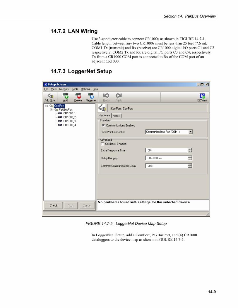
Section 14. PakBus Overview
14-9
14.7.2 LAN Wiring Use 3-conductor cable to connect CR1000s as shown in FIGURE 14.7-1. Cable length between any two CR1000s must be less than 25 feet (7.6 m). COM1 Tx (transmit) and Rx (receive) are CR1000 digital I/O ports C1 and C2 respectively; COM2 Tx and Rx are digital I/O ports C3 and C4, respectively. Tx from a CR1000 COM port is connected to Rx of the COM port of an adjacent CR1000.
14.7.3 LoggerNet Setup
FIGURE 14.7-5. LoggerNet Device Map Setup
In LoggerNet | Setup, add a ComPort, PakBusPort, and (4) CR1000 dataloggers to the device map as shown in FIGURE 14.7-5.

Section 14. PakBus Overview
14-10
FIGURE 14.7-6. LoggerNet Device Map Setup: PakBusPort
As shown in FIGURE 14.7-6, set the PakBusPort maximum baud rate to 115200. Leave other settings at the defaults.

Section 14. PakBus Overview
14-11
FIGURE 14.7-7. LoggerNet Device Map Setup: Dataloggers
As shown in FIGURE 14.7-7, set the PakBus address for each CR1000 as listed in TABLE 14.7-1.

Section 14. PakBus Overview
14-12

15-1
Section 15. Alternate Telecoms Resource Library
15.1 DNP3 15.1.1 Overview
The CR1000 is DNP3 SCADA compatible. DNP3 is a SCADA protocol primarily used by utilities, power generation and distribution networks, and the water and wastewater treatment industry.
Distributed Network Protocol (DNP) is an open protocol used in applications to ensure data integrity using minimal bandwidth. DNP implementation in the CR1000 is DNP3 level 2 Slave compliant with some of the operations found in a level 3 implementation. A standard CR1000 program with DNP instructions will take arrays of real time or processed data and map them to DNP arrays in integer or binary format. The CR1000 responds to any DNP master with the requested data or sends unsolicited responses to a specific DNP master. DNP communications are supported in the CR1000 through the RS-232 port, COM1 - COM4, or over TCP, taking advantage of multiple communications options compatible with the CR1000, e.g., RF, cellular phone, satellite. DNP3 state and history are preserved through power and other resets in non-volatile memory.
DNP SCADA software enables CR1000 data to move directly into a database or display screens. Applications include monitoring weather near power transmission lines to enhance operational decisions, monitoring and controlling irrigation from a wastewater treatment plant, controlling remote pumps, measuring river flow, and monitoring air movement and quality at a power plant.
15.1.2 Programming for DNP3 EXAMPLE 15.1-1 lists CRBASIC code to take Iarray() analog data and Barray() binary data (status of control port 5) and map them to DNP arrays. The CR1000 responds to a DNP master with the specified data or sends unsolicited responses to DNP Master 3.
15.1.2.1 Declarations TABLE 15.1-1 shows object groups supported by the CR1000 DNP implementation, and the required data types. A complete list of groups and variations is available in CRBASIC Help for DNPVariable().

Section 15. Alternate Telecoms Resource Library
15-2
TABLE 15.1-1. CRBASIC Data Types Required to Store Data in the
Public Table for each Object Group.
Data Type Group Description
Boolean 1 Binary Input
2 Binary Input Change
10 Binary Output
12 Control Block
Long 30 Analog Input
32 Analog Change Event
40 Analog Output Status
41 Analog Output Block
50 Time and Date
51 Time and Date CTO
15.1.2.2 CRBASIC Instructions Complete descriptions and options of commands are available in CRBASIC Editor Help.
DNP()
Sets the CR1000 as a DNP slave (outstation/server) with an address and DNP3 dedicated COM port. Normally resides between BeginProg and Scan(), so is executed only once. Example at Example 15.1-1, line 20.
Syntax DNP (ComPort, BaudRate, DNPSlaveAddr)
DNPVariable ()
Associates a particular variable array with a DNP object group. When the master polls the CR1000, it returns all the variables specified along with their specific groups. Also used to set up event data, which is sent to the master whenever the value in the variable changes. Example at Example 15.1-1, line 24.
Syntax DNPVariable (Source, Swath, DNPObject, DNPVariation,
DNPClass, DNPFlag, DNPEvent, DNPNumEvents)
DNPUpdate ()
Determines when DNP slave (outstation/server) will update its arrays of DNP elements. Specifies the address of the DNP master to which are sent unsolicited responses (event data). Must be included once within a Scan/NextScan for the DNP slave to update its arrays. Typically placed in a

Section 15. Alternate Telecoms Resource Library
15-3
program after the elements in the array are updated. The CR1000 will respond to any DNP master regardless of its address.
Syntax DNPUpdate (DNPMasterAddr)
15.1.2.3 Programming for Data Acquisition To program the CR1000 to return data when polled by the DNP3 master,
• place DNP() at the beginning of the program between BeginProg and Scan(). Set COM port, baud rate, and DNP3 address.
• setup the variables to be sent to the master using DNPVariable(). Dual instructions cover static (current values) and event (previous ten records) data.
o For analog measurements: DNPVariable(Variable_Name,Swath,30,2,0,&B00000000,0,0) DNPVariable(Variable_Name,Swath,32,2,3,&B00000000,0,10)
o For digital measurements (control ports): DNPVariable(Variable_Name,Swath,1,2,0,&B00000000,0,0) DNPVariable(Variable_Name,Swath,32,2,3,&B00000000,0,10)
• place DNPUpdate() after Scan(), inside the main scan. The DNP3 master is notified of any change in data each time DNPUpdate() runs; e.g for a 10 second scan, the master is notified every 10 seconds.
15.1.2.4 Programming for Control Variables inside the CR1000 can be set by the DNP3 master to setup the CR1000 to accept control commands.
• place DNP() at the beginning of the program between BeginProg and Scan(). Set COM port, baud rate, and DNP3 address.
• setup the variables to be set by the master using DNPVariable(). Dual instructions maintain compatibility with DNP3 implementations.
o For analog variables: DNPVariable(Variable_Name,Swath,40,2,0,&B00000000,0,0) DNPVariable(Variable_Name,Swath,41,2,0,&B00000000,0,0)
o For digital variables (control ports): DNPVariable(Variable_Name,Swath,10,1,0,&B00000000,0,0) DNPVariable(Variable_Name,Swath,12,1,0,&B00000000,0,0)
• place DNPUpdate() after Scan(), inside the main scan. Variables are updated each time this command runs.
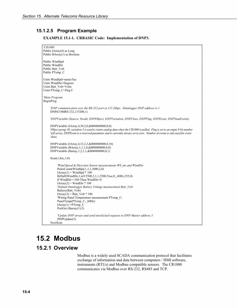
Section 15. Alternate Telecoms Resource Library
15-4
15.1.2.5 Program Example EXAMPLE 15.1-1. CRBASIC Code: Implementation of DNP3.
'CR1000 Public IArray(4) as Long Public BArray(1) as Boolean Public WindSpd Public WindDir Public Batt_Volt Public PTemp_C Units WindSpd=meter/Sec Units WindDir=Degrees Units Batt_Volt=Volts Units PTemp_C=Deg C 'Main Program BeginProg 'DNP communication over the RS-232 port at 115.2kbps. Datalogger DNP address is 1 DNP(COMRS-232,115200,1) 'DNPVariable (Source, Swath, DNPObject, DNPVariation, DNPClass, DNPFlag, DNPEvent, DNPNumEvents) DNPVariable (IArray,4,30,2,0,&B00000000,0,0) 'Object group 30, variation 2 is used to return analog data when the CR1000 is polled. Flag is set to an empty 8 bit number '(all zeros), DNPEvent is a reserved parameter and is currently always set to zero. Number of events is only used for event 'data. DNPVariable (IArray,4,32,2,3,&B00000000,0,10) DNPVariable (BArray,1,1,1,0,&B00000000,0,0) DNPVariable (Barray,1,2,1,1,&B00000000,0,1) Scan(1,Sec,1,0) 'Wind Speed & Direction Sensor measurements WS_ms and WindDir: PulseCount(WindSpd,1,1,1,3000,2,0) IArray(1) = WindSpd * 100 BrHalf(WindDir,1,mV2500,3,1,1,2500,True,0,_60Hz,355,0) If WindDir>=360 Then WindDir=0 IArray(2) = WindDir * 100 'Default Datalogger Battery Voltage measurement Batt_Volt: Battery(Batt_Volt) IArray(3) = Batt_Volt * 100 'Wiring Panel Temperature measurement PTemp_C: PanelTemp(PTemp_C,_60Hz) IArray(1) =PTemp_C PortGet (Barray(1),5) 'Update DNP arrays and send unsolicited requests to DNP Master address 3 DNPUpdate(3) NextScan
15.2 Modbus 15.2.1 Overview
Modbus is a widely used SCADA communication protocol that facilitates exchange of information and data between computers / HMI software, instruments (RTUs) and Modbus compatible sensors. The CR1000 communicates via Modbus over RS-232, RS485 and TCP.

Section 15. Alternate Telecoms Resource Library
15-5
Modbus systems consist of a master (PC), RTU / PLC slaves, field instruments (sensors), and the communications network hardware. The communications port, baud rate, data bits, stop bits, and parity are set in the Modbus driver of the master and / or the slaves. The Modbus standard has two communications modes, RTU and ASCII. However, CR1000s communicate in RTU mode exclusively.
Field instruments can be queried by the CR1000. Because Modbus has a set command structure, programming the CR1000 to get data from field instruments is much simpler than from serial sensors. Because Modbus uses a common bus and addresses each node, field instruments are effectively multiplexed to a CR1000 without additional hardware.
A CR1000 goes into sleep mode after 40 seconds of communications inactivity. Once asleep, two packets are required before the CR1000 will respond. The first packet awakens the CR1000; the second packet is received as data. CR1000s, through DevConfig or the status table (Appendix B) can be set to keep communications ports open and awake, but at higher power usage.
15.2.2 Terminology TABLE 15.2-1 lists terminology equivalents to aid in understanding how CR1000s fit into a SCADA system.
TABLE 15.2-1. Modbus to Campbell Scientific Equivalents
Modbus Domain Data Form Campbell Scientific Domain
Coils Single Bit Ports, Flags, Boolean Variables
Digital Registers 16-bit Word Floating Point Variables
Input Registers 16-bit Word Floating Point Variables
Holding Registers 16-bit Word Floating Point Variables
RTU / PLC CR1000
Master Usually a computer
Slave Usually a CR1000
Field Instrument Sensor
15.2.2.1 Glossary of Terms Coils (00001 to 09999)
Originally, “coils” referred to relay coils. In CR1000s, coils are exclusively ports, flags, or a Boolean variable array. Ports are inferred if parameter 5 of the ModbusSlave instruction is set to 0. Coils are assigned to Modbus registers 00001 to 09999.
Digital Registers 10001-19999 Hold values resulting from a digital measurement. Digital registers in the Modbus domain are read only. In the CSI domain, the leading digit in Modbus registers is ignored, and so are assigned together to a single Dim or Public variable array (read / write).

Section 15. Alternate Telecoms Resource Library
15-6
Input Registers 30001 - 39999 Hold values resulting from an analog measurement. Input registers in the Modbus domain are read only. In the CSI domain, the leading digit in Modbus registers is ignored, and so are assigned together to a single Dim or Public variable array (read / write).
Holding Registers 40001 - 49999 Hold values resulting from a programming action. Holding registers in the Modbus domain are read / write. In the CSI domain, the leading digit in Modbus registers is ignored, and so are assigned together to a single Dim or Public variable array (read / write).
RTU / PLC Remote Telemetry Units (RTUs) and Programmable Logic Controllers (PLCs) were at one time used in exclusive applications. As technology increases, however, the distinction between RTUs and PLCs becomes more blurred. A CR1000 fits both RTU and PLC definitions.
15.2.3 Programming for Modbus 15.2.3.1 Declarations
TABLE 15.2-2 shows the linkage between CR1000 ports, flags and Boolean variables and Modbus registers. Modbus does not distinguish between CR1000 ports, flags, or Boolean variables. By declaring only ports, or flags, or Boolean variables, the declared feature is addressed by default. A typical CRBASIC program for a Modbus application will declare variables and ports, or variables and flags, or variables and Boolean variables.
TABLE 15.2-2. Linkage between CR1000 Ports, Flags, and Variables and Modbus Registers.
CR1000 Feature
Example CRBASIC Declaration
Equivalent Example Modbus Register
Control Port (Port) Public Port(8) 00001 to 00009
Flag Public Flag(17) 00001 to 00018
Boolean Variable Public ArrayB(56) as Boolean 00001 to 00057
Variable Public ArrayV(20)* 40001 to 40041* or 30001 to 30041*
*Because of byte number differences, each CR1000 domain variable translates to two Modbus domain input / holding registers.
15.2.3.2 CRBASIC Instructions Complete descriptions and options of commands are available in CRBASIC Editor Help.

Section 15. Alternate Telecoms Resource Library
15-7
ModbusMaster () Sets up a CR1000 as a Modbus master to send or retrieve data from a Modbus slave.
Syntax ModbusMaster (ResultCode, ComPort, BaudRate, ModbusAddr, Function, Variable, Start, Length, Tries, TimeOut)
ModbusSlave () Sets up a CR1000 as a Modbus slave device.
Syntax ModbusSlave (ComPort, BaudRate, ModbusAddr, DataVariable, BooleanVariable)
MoveBytes () Moves binary bytes of data into a different memory location when translating big endian to little endian data.
Syntax MoveBytes (Dest, DestOffset, Source, SourceOffset, NumBytes)
15.2.3.3 Addressing (ModbusAddr) Modbus devices have a unique address in each network. Addresses range from 1 to 247. Address 0 is reserved for universal broadcasts. When using the NL100, use the same number as the Modbus and Pakbus address.
15.2.3.4 Supported Function Codes (Function) Modbus protocol has many function codes. CR1000 commands support the following.
01 Read Coil Status 02 Read Input Status 03 Read Holding Registers 04 Read Input Registers 05 Force Single Coil 15 Force Multiple Coils 16 Force Multiple Registers
15.2.3.5 Reading Inverse Format Registers Some Modbus devices require reverse byte order words (CDAB vs. ABCD). This can be true for either floating point, or integer formats. Since a slave CR1000 uses the ABCD format, either the master has to make an adjustment, which is sometimes possible, or the CR1000 needs to output reverse byte order words. To reverse the byte order, use the MoveBytes () instruction as shown in the sample code below.
for i = 1 to k MoveBytes (InverseFloat(i),2,Float(i),0,2) MoveBytes (InverseFloat(i),0,Float(i),2,2) next

Section 15. Alternate Telecoms Resource Library
15-8
In the example above InverseFloat(i) is the array holding the inverse byte ordered word (CDAB). Array Float(i) holds the obverse byte ordered word (ABCD).
15.2.4 Troubleshooting Test Modbus functions on the CR1000 with third party Modbus software. Further information is available at the following links:
http://www.simplyModbus.ca/FAQ.htm http://www.Modbus.org/tech.php http://www.lammertbies.nl/comm/info/modbus.html
15.2.5 Modbus over IP Modbus over IP functionality is an option with the CR1000. Contact Campbell Scientific for details.
15.2.6 ModBus tidBytes • Question:
Can Modbus be used over an RS-232 link, 7 data bits, even parity, one stop bit? Answer: Yes. Precede ModBusMaster() / ModBusSlave() with SerialOpen() set the numeric format of the COM port with any of the available formats, including the option of 7 data bits, even parity. SerialOpen() and ModBusMaster() can be used once and placed before Scan().
• Concatenating two Modbus long 16-bit variables to one Modbus long 32 bit number.
EXAMPLE 15.2-1. CRBASIC Code: Concatenating Modbus Long Variables.
'Requires CR1000 OS v. 12 or higher 'CR1000 uses Big-Endien word order. ‘Declarations Public Combo As Long 'Combo is the variable that will hold the combined 32-bit Public Register(2) As Long 'Array holds two 16-bit ModBus long variables 'Register(1) = Least Significant Word 'Register(2) = Most Significant Word Public Result 'Holds the result of the ModBus master query 'Aliases used for clarification Alias Register(1) = Register_LSW 'Least significant word. Alias Register(2) = Register_MSW 'Most significant word. BeginProg 'If you use the numbers below (un-comment them first) Combo is read as 131073 decimal 'Register_LSW=&h0001 'Least significant word. 'Register_MSW=&h0002 ' Most significant word.

Section 15. Alternate Telecoms Resource Library
15-9
Scan(1,Sec,0,0) 'In the case of the CR1000 being the ModBus master then the ModbusMaster instruction would 'be used (instead of fixing the variables as shown between the BeginProg and SCAN instructions). ModbusMaster (Result,COMRS232,-115200,5,3,-Register(1),1,2,3,100) 'MoveBytes(DestVariable,DestOffset,SourceVariable,SourceOffSet,NumberOfBytes) MoveBytes(Combo,2, Register_LSW,2,2) MoveBytes(Combo,0, Register_MSW,2,2) NextScan EndProg

Section 15. Alternate Telecoms Resource Library
15-10

16-1
Section 16. Support Software PC / Windows® compatible software products are available from Campbell Scientific to facilitate CR1000 programming, maintenance, data retrieval, and data presentation. Short Cut, PC200W, and Visual Weather are designed for novice integrators, but have features useful in advanced applications. PC400 and LoggerNet provide increasing levels of power required for advanced integration, programming and networking applications. Support software for PDA and Linux applications are also available.
16.1 Short Cut Short Cut utilizes an intuitive user interface to create CR1000 program code for common measurement applications. It presents lists from which sensors, engineering units, and data output formats are selected. It supports by name most sensors sold by Campbell Scientific. It features “generic” measurement routines, enabling it to support many sensors from other manufacturers. Programs created by Short Cut are automatically well documented and produce examples of CRBASIC programming that can be used as source or reference code for more complex programs edited with CRBASIC Editor.
Short Cut is included with PC200W, Visual Weather, PC400, RTDAQ, and LoggerNet and is available at no charge from the Campbell Scientific web site.
16.2 PC200W PC200W utilizes an intuitive user interface to support direct serial communication to the CR1000 via COM / RS-232 ports. It sends programs, collects data, and facilitates monitoring of digital measurement and process values. PC200W is available at no charge from the Campbell Scientific web site.
16.3 Visual Weather Visual Weather supports weather stations. It is recommended in applications wherein the user requires minimal control over programming and the pre-configured display and reporting features. Visual Weather is highly integrated and easy to use.
16.4 PC400 PC400 is a mid-level software suite. It includes CRBASIC Editor, point-to-point communications over several communications protocols, simple real-time digital and graphical monitors, and report generation. It does not support scheduled collection or multi-mode communication networks.
16.5 RTDAQ RTDAQ is targeted for industrial and other high-speed data acquisition applications.

Section 16. Support Software
16-2
16.6 LoggerNet Suite The LoggerNet suite utilizes a client-server architecture that facilitates a wide range of applications and enables tailoring software acquisition to specific requirements. TABLE 16.6-1 lists features of LoggerNet products that include the LoggerNet server. TABLE 16.6-2 lists features of LoggerNet products that require the LoggerNet server as an additional purchase.
TABLE 16.6-1. LoggerNet Products that Include the LoggerNet Server
LoggerNet Datalogger management, programming, data collection, scheduled data collection, network monitoring and troubleshooting, graphical data displays, automated tasks, data viewing and post-processing.
LoggerNet Admin All LoggerNet features plus network security, manages the server from a remote PC, runs LoggerNet as a service, exports data to third party applications, launches multiple instances of the same client, e.g., two or more functioning Connect windows.
LoggerNet Remote Allows management of an existing LoggerNet datalogger network from a remote location, without investing in another complete copy of LoggerNet Admin.
LoggerNet-SDK Allows software developers to create custom client applications that communicate through a LoggerNet server with any datalogger supported by LoggerNet. Requires LoggerNet.
LoggerNet Server – SDK Allows software developers to create custom client applications that communicate through a LoggerNet server with any datalogger supported by LoggerNet. Includes the complete LoggerNet Server DLL, which can be distributed with the custom client applications.
LoggerNet Linux Includes LoggerNet Server for use in a Linux environments and LoggerNet Remote for managing the server from a Windows environment.

Section 16. Support Software
16-3
TABLE 16.6-2. LoggerNet Clients
(require, but do not include, the LoggerNet Server)
Baler Handles data for third-party application feeds.
RTMCRT RTMC viewer only.
RTMC Web Server Converts RTMC graphics to HTML.
RTMC Pro Enhanced version of RTMC.
LoggerNetData Displays / Processes real-time and historical data.
CSI OPC Server Feeds data into third-party OPC applications.
16.7 PDA Software PConnect Software supports PDAs with Palm Operating Systems. PConnectCE supports Windows Mobile and Pocket PC PDAs. Both support direct RS-232 connection to the CR1000 for sending programs, collecting data, and digital real-time monitoring.

Section 16. Support Software
16-4
This is a blank page.

17-1
Section 17. CR1000KD: Using the Keyboard Display
Read More! See Section 11.6 CR1000KD Custom Menus.
The CR1000 has an optional keyboard display, the CR1000KD. This section illustrates the use of the CR1000KD using its default menus. The CR1000KD has a few keys that have special functions which are listed below.
Although the CR1000KD is not required to operate or use the CR1000, it is a useful diagnostic and debugging tool.
Key Usage
[2] and [8] To navigate up and down through the menu list one line at a time
[Enter] Selects the line or toggles the option of the line the cursor is on
[Esc] Back up one level in the menu
[Home] Move cursor to top of the list
[End] Move cursor to bottom of the list
[Pg Up] Move cursor up one screen
[Pg Dn] Move cursor down one screen
[BkSpc] Delete character to the left
[Shift] Change alpha character selected
[Num Lock] Change to numeric entry
[Del] Delete
[Ins] Insert/change graph setup
[Graph] Graph
NOTE

Section 17. CR1000KD: Using the Keyboard Display
17-2
CR1000 Display
CAMPBELL SCIENTIFIC
CR1000 Datalogger
06/18/2000, 18:24:35 CPU: TRIG.CR1
Running.
Real Time Tables Real Time Custom Final Storage Data Reset Data Tables Graph Setup
Active Tables Format Card PCCard is only in the menu if a CF card module is attached, and it has a card in it.
Data Run/Stop Program File PCCard Ports and Status Configure, Settings
Port Status Table
New Edit Copy Delete Run Options Directory Format
Power Up Screen
Press any key for Main Menu (except , , , or Esc)
Toggle backlight with Adjust contrast with
Set Time/Date Settings Display
Options depend on program state
Any key to turn on display [End] to turn off display

Section 17. CR1000KD: Using the Keyboard Display
17-3
17.1 Data Display
Data Run/Stop Program File PCCard Ports and Status Configure, Settings
List of Data Tables created by active program
List of User-Selected Variables (blank if not set up)
Real Time Tables Real Time Custom Final Storage Data Reset Data Tables Graph Setup
Graph Type Roll Scaler Manual Upper: 0.000000 Lower: 0.000000 Display Val On Display Max On Display Min On
List of Data Tables created by active program
Move the cursor to Data and press Enter
All Tables List of Data Tables created by active program
Roll/Scope Manual/Auto
Not shown if “Auto”
On/Off On/Off On/Off
Scope requires manual scalar

Section 17. CR1000KD: Using the Keyboard Display
17-4
17.1.1 Real Time Tables
Public Table1 Temps
Tref : 23.0234 TCTemp(1) : 19.6243 TCTemp(2) : 19.3429 TCTemp(3) : 21.2003 Flag(1) : -1.0000 Flag(2) : 0.00000 Flag(3) : 0.00000 Flag(4) : 0.00000
Scaler Manual Upper: 30.000000 Lower: 20.000000 Display Val On Display Max On Display Min On Graph Type Roll
30.0 22.35 _____ ___ ____ __ 20.00
List of Data Tables created by active program. For Example,
Move the cursor to desired table and press Enter
TCTemp(3) :
Public Table values can be changed. Move the cursor to value and press Enter to edit value.
Press Graph for graph of selected field
Press Ins for Graph Setup
New values are displayed as they are stored.
Edit field: Num TCTemp(3) Current Value: 21.2003 New Value:
Auto/Manual
On/Off On/Off On/Off Roll/Scope
Move the cursor to setting and press Enter to change
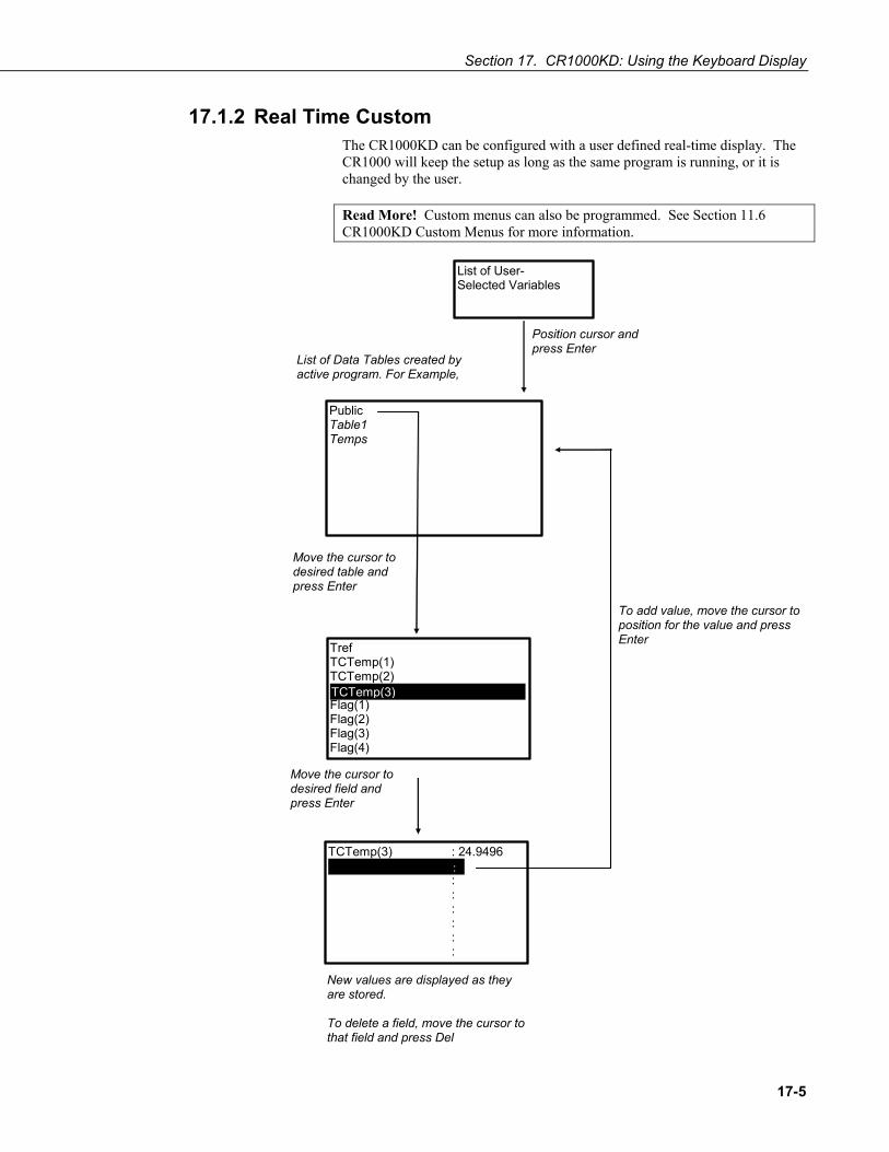
Section 17. CR1000KD: Using the Keyboard Display
17-5
17.1.2 Real Time Custom The CR1000KD can be configured with a user defined real-time display. The CR1000 will keep the setup as long as the same program is running, or it is changed by the user.
Read More! Custom menus can also be programmed. See Section 11.6 CR1000KD Custom Menus for more information.
Public Table1 Temps
Tref TCTemp(1) TCTemp(2) TCTemp(3) Flag(1) Flag(2) Flag(3) Flag(4)
TCTemp(3) : 24.9496 : : : : : :
List of Data Tables created by active program. For Example,
Move the cursor to desired table and press Enter
TCTemp(3)
New values are displayed as they are stored. To delete a field, move the cursor to that field and press Del
Move the cursor to desired field and press Enter
:
To add value, move the cursor to position for the value and press Enter
List of User- Selected Variables
Position cursor and press Enter
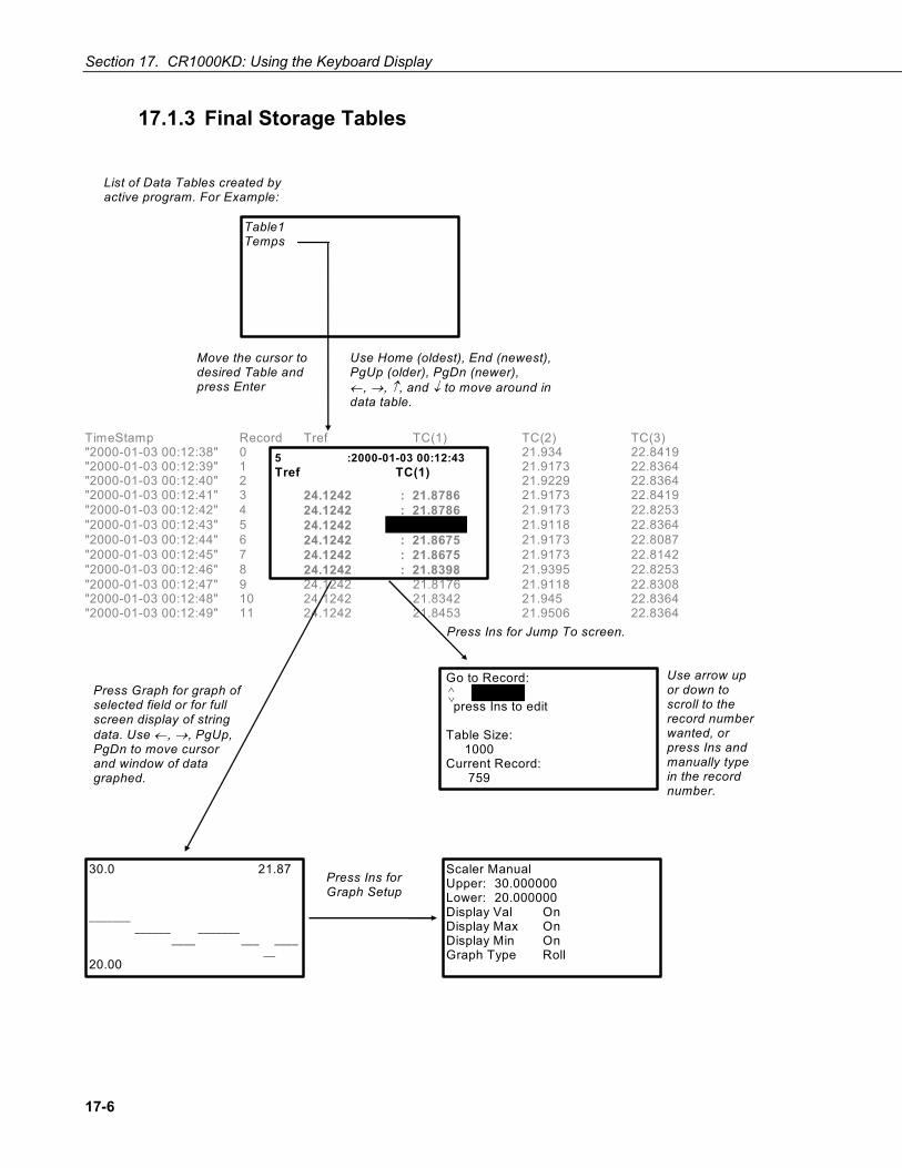
Section 17. CR1000KD: Using the Keyboard Display
17-6
17.1.3 Final Storage Tables
TimeStamp Record Tref TC(1) TC(2) TC(3) "2000-01-03 00:12:38" 0 21.934 22.8419 "2000-01-03 00:12:39" 1 24.1242 21.8619 21.9173 22.8364 "2000-01-03 00:12:40" 2 24.1242 21.8786 21.9229 22.8364 "2000-01-03 00:12:41" 3 24.1242 : 21.8786 21.9173 22.8419 "2000-01-03 00:12:42" 4 24.1242 : 21.8786 21.9173 22.8253 "2000-01-03 00:12:43" 5 24.1242 : 21.8675 21.9118 22.8364 "2000-01-03 00:12:44" 6 24.1242 : 21.8675 21.9173 22.8087 "2000-01-03 00:12:45" 7 24.1242 : 21.8675 21.9173 22.8142 "2000-01-03 00:12:46" 8 24.1242 : 21.8398 21.9395 22.8253 "2000-01-03 00:12:47" 9 24.1242 21.8176 21.9118 22.8308 "2000-01-03 00:12:48" 10 24.1242 21.8342 21.945 22.8364 "2000-01-03 00:12:49" 11 24.1242 21.8453 21.9506 22.8364
Press Ins for Jump To screen.
Press Graph for graph of selected field or for full screen display of string data. Use ←, →, PgUp, PgDn to move cursor and window of data graphed.
5 :2000-01-03 00:12:43Tref TC(1)
21.8675
List of Data Tables created by active program. For Example:
Table1 Temps
Move the cursor to desired Table and press Enter
Use Home (oldest), End (newest), PgUp (older), PgDn (newer), ←, →, ↑, and ↓ to move around in data table.
Scaler Manual Upper: 30.000000 Lower: 20.000000 Display Val On Display Max On Display Min On Graph Type Roll
30.0 21.87 _______ ______ _______ ____ ___ ____ __ 20.00
Press Ins for Graph Setup
Go to Record: press Ins to edit Table Size: 1000 Current Record: 759
5 ∧∨
Use arrow up or down to scroll to the record number wanted, or press Ins and manually type in the record number.

Section 17. CR1000KD: Using the Keyboard Display
17-7
17.2 Run/Stop Program
CPU: ProgramName.CR1 Is Running >* Run on Power Up Stop, Retain Data Stop, Delete Data Restart, Retain Data Restart, Delete Data Execute
CPU: ProgramName.CR1 Is Stopped >* Run on Power Up Stop, Delete Data Restart, Retain Data Restart, Delete Data Execute
CPU: CRD: or list of program files on CPU if no card is present
Data Run/Stop Program File PCCard Ports and Status Configure, Settings
Press escape to cancel or get list of available programs.
Press escape to cancel or get list of available programs.
Press escape to cancel.
Select 1 (press Enter) and move the cursor to Execute. Press Enter to execute.
Select 1 (press Enter) and move the cursor to Execute. Press Enter to execute.
Select location of program file.
If program is running
If program is stopped
No program running or stopped
Move the cursor to run/stop program and press Enter.

Section 17. CR1000KD: Using the Keyboard Display
17-8
17.3 File Display
Data Run/Stop Program File PCCard Ports and Status Configure, Settings
New File Name: CPU: .CR1 CRD: .CR1
CPU: CRD: New
Edit Copy Delete Run Options Directory Format
Copy From To Execute
Move the cursor to File and press Enter
List of files on CPU or Card.

Section 17. CR1000KD: Using the Keyboard Display
17-9
17.3.1 File: Edit The CRBASIC Editor is recommended for writing and editing datalogger programs. Changes in the field can be made with the keyboard display. When making changes to the program with the CR1000KD, stop the program then restart it to active the changes.
Press Ins
ESC
CPU: TCTEMP.CR1 0 RACE.CR1 0
CR1000 ' TCTemp.CR1 Public TREF,TC(3),FLAG(8) D ataTable (Temps,1,1000) Sample (1,TREF,IEEE4) Sample (3,TC(),IEEE4) E dT bl
ENTER Edit Instruction Blank Line Create Block
List of Program files on CPU: or CRD: For Example:
Move the cursor to desired Program and press Enter
Edit Directly or move cursor to first character of line and press Enter
D
INSERT Instruction Function Blank Line Block Insert Off
DataTable TableName > Temps TrigVar 1 Size 1000
Block Commands Copy Cut Delete
Insert blank line
DataTable (Temps,1,1000) Sample (1,TREF,IEEE4) Sample (3,TC(),IEEE4) EndTable BeginProg Scan(1,sec,3,0)
Edit Instruction parameters with parameter names and some pick lists:
DataTable (Temps,1,1000) Move the cursor to highlight desired block and press Enter
To insert a block created by this operation, move the cursor to desired place in program and press Ins.
Save Changes? Yes No

Section 17. CR1000KD: Using the Keyboard Display
17-10
17.4 PCCard Display
Data Run/Stop Program File PCCard Ports and Status Configure, Settings
All Card Data Will be Lost!
Proceed? Yes No
Active Tables Format Card
List of Data Tables on card used by active program
Move the cursor to PCCard and press Enter
PCCard is only in menu if a CF card module is attached and a CF card is inserted.

Section 17. CR1000KD: Using the Keyboard Display
17-11
17.5 Ports and Status
Read More! See Appendix A Status Table
List of Status Variables (see Appendix A)
Ports Status Table
PortStatus (1): OFF PortStatus (2): OFF PortStatus (3): OFF PortStatus (4): OFF PortStatus (5): OFF PortStatus (6): OFF PortStatus (7): OFF PortStatus (8): OFF
Move the cursor to the desired port and press Enter to toggle OFF/ON. The port must be configured as an output to be toggled.

Section 17. CR1000KD: Using the Keyboard Display
17-12
17.6 Settings
Set Time/Date Settings Display
Routes : xxxx StationName : xxxx PakBusAddress : xxxx Security(1) : xxxx Security(2) : xxxx Security(3) : xxxx IsRouter : xxxx PakBusNodes : xxxx
Turn Off Display Back Light Contrast Adjust Display Timeout: Yes Timeout (min): 4
05/24/2000, 15:10:40 Year 2000 Month 5 Day 24 Hour 15 Minute 10 Set Cancel
Move the cursor to time element and press Enter to change

Section 17. CR1000KD: Using the Keyboard Display
17-13
17.6.1 Set Time / Date Move the cursor to time element and press Enter to change it. Then move the cursor to Set and press Enter to apply the change.
17.6.2 PakBus Settings In the Settings menu, move the cursor to the PakBus element and press Enter to change it. After modifying, press Enter to apply the change.
17.6.3 Configure Display
Set Time/Date Settings Display
Light Dark <- * ->
Turn Off Display Backlight Contrast Adjust Display Timeout: Yes Timeout (min): 4
Move the cursor to Configure Display and press Enter
Enter display timeout in minutes (max = 60)
Yes/No
On/Off
Press Enter to turn off Display

Section 17. CR1000KD: Using the Keyboard Display
17-14
This is a blank page.

18-1
Section 18. Care and Maintenance Temperature and humidity can affect the performance of the CR1000. The internal lithium battery must be replaced periodically.
18.1 Temperature Range The standard CR1000 is designed to operate reliably from -25 to +50°C (-40°C to +85°C, optional) in non-condensing humidity.
18.2 Moisture Protection When humidity tolerances are exceeded and condensation occurs, damage to CR1000 electronics can result. Effective humidity control is the responsibility of the user.
Internal CR1000 module moisture is controlled at the factory by sealing the module with a packet of silica gel inside. The desiccant is replaced whenever the CR1000 is repaired at Campbell Scientific. The module should not be opened by the user except to replace the lithium coin cell providing back up power to the clock and SRAM. Repeated disassembly of the CR1000 will degrade the seal, leading to potential moisture problems.
Adequate desiccant should be placed in the instrumentation enclosure to prevent corrosion on the CR1000 wiring panel.
18.3 Enclosures Campbell Scientific offers environmental enclosures for housing a CR1000 and peripherals. These enclosures are classified as NEMA 4X (watertight, dust-tight, corrosion-resistant, indoor and outdoor use). Refer to Appendix F.4 for information concerning available enclosures.

Section 18. Care and Maintenance
18-2
18.4 Replacing the Internal Battery Misuse of the lithium battery or installing it improperly can cause severe injury. Fire, explosion, and severe burn hazard! Do not recharge, disassemble, heat above 100°C (212°F), solder directly to the cell, incinerate, nor expose contents to water. Dispose of spent lithium batteries properly.
The CR1000 contains a lithium battery that operates the clock and SRAM when the CR1000 is not powered. The CR1000 does not draw power from the lithium battery while it is powered by a 12 VDC supply. In a CR1000 stored at room temperature, the lithium battery should last approximately 10 years (less at temperature extremes). Where the CR1000 is powered most or all of the time the lithium cell should last much longer.
While powered from an external source, the CR1000 measures the voltage of the lithium battery daily. This voltage is displayed in the status table (Appendix A). A new battery will have approximately 3.6 volts. The CR1000 Status Table has a “Lithium Battery” field. This field shows lithium battery voltage. Replace the battery when voltage is approximately 2.7 V. If the lithium cell is removed or allowed to discharge below the safe level, the CR1000 will still operate correctly while powered. Without the lithium battery, the clock will reset and data is lost when power is removed.
The CR1000 is partially disassembled to replace the lithium cell. When the lithium battery is removed, the user program and most settings is maintained. Items not retained include
• Run now and run on power-up settings. • Routing and communications logs (relearned without user
intervention). • Time. Clock will need resetting when the battery is replaced. • Final storage data tables.
A replacement lithium battery can be purchased from Campbell (part number 13519). TABLE 18.4-1 lists the specifications of the battery.
TABLE 18.4-1. CR1000 Lithium Battery Specifications
Manufacturer Tadiran
Model TL-59025 (3.6 V)
Capacity 1.2 Ah
Self-discharge rate 1%/year @ 20°C
Operating temperature range -55°C to 85°C
FIGURE 18.4-1 through FIGURE 18.4-5 illustrate how to disassemble the CR1000. Reverse these steps to reassemble the CR1000.
CAUTION
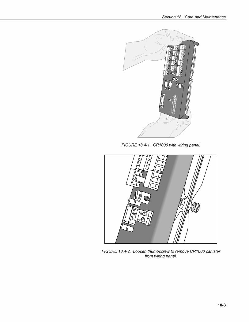
Section 18. Care and Maintenance
18-3
Lo
ga
n, U
tah
FIGURE 18.4-1. CR1000 with wiring panel.
FIGURE 18.4-2. Loosen thumbscrew to remove CR1000 canister from wiring panel.
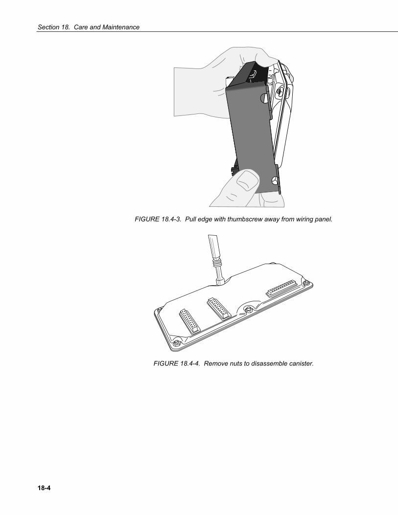
Section 18. Care and Maintenance
18-4
FIGURE 18.4-3. Pull edge with thumbscrew away from wiring panel.
FIGURE 18.4-4. Remove nuts to disassemble canister.
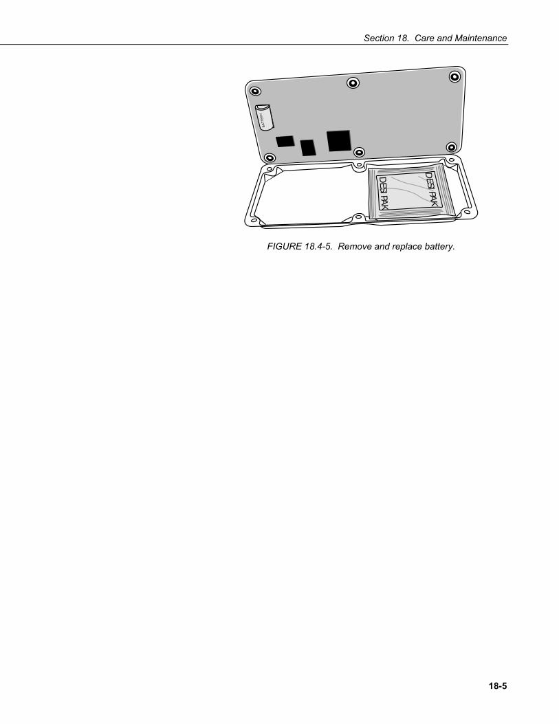
Section 18. Care and Maintenance
18-5
DESI PA
K
DESI PA
K
BATT
ERY
FIGURE 18.4-5. Remove and replace battery.

Section 18. Care and Maintenance
18-6
This is a blank page.

19-1
Section 19. Troubleshooting If any component needs to be returned to the factory for repair or recalibration, remember that an RMA number is required. Contact a Campbell Scientific applications engineer to receive the RMA number.
19.1 Programming 19.1.1 Debugging Resources
A properly deployed CR1000 measures sensors accurately and stores all data as requested by the program. Experienced users analyze measurement data soon after deployment to ensure the CR1000 is measuring and storing data as desired by the programmer. Most measurement and data storage problems are a result of one or more instances of improper program code or “bugs.”
Consult the CR1000 Status Table when developing a program or when a problem with a program is suspected. Critical Status Table registries to review include:
Read More! See Appendix A for a complete list of Status Table registers and hints on using the Status Table.
19.1.1.1 Compile Results Reports messages generated by the CR1000 at program upload and compile-time. A message will report that the program compiled OK or that there are run-time errors. Error messages may not be obvious because the display column is too short. Messages report variables that caused out-of-bounds conditions, watchdog information, and memory errors. Messages may be tagged onto this line as the program runs. A rare error is indicated by "mem3 fail" type messages. These messages can be caused by random internal memory corruption. When seen on a regular basis with a given program, an operating system error is indicated. “Mem3 fail” messages are not caused by user error, and only rarely by a hardware fault. Report any occurrence of this error to a Campbell Scientific applications engineer, especially if the problem is reproducible. Any program generating these errors is unlikely to be running correctly.
19.1.1.2 SkippedScan Skipped scans are caused by long programs with short scan intervals, multiple Scan () / NextScan () instructions outside a SubScan () or SlowSequence (), or when other operations, that occupy the processor at a scan’s start time. Occasional skipped scans may be acceptable but should be avoided. Skipped scans may compromise frequency measurements made with pulse channels. The error occurs because counts from a scan and subsequent skipped scans are regarded by the CR1000 as having occurred during a single scan. The measured frequency can be much higher than actual. Be careful that scans that store data are not skipped. If any scan skips repeatedly, optimization of the datalogger program or reduction of online processing may be necessary.
NOTE

Section 19. Troubleshooting
19-2
Skipped scans in Pipeline Mode indicate an increase in the maximum buffer depth is needed. Try increasing the number of scan buffers (third parameter of the Scan () instruction) to a value greater than that shown in the MaxBuffDepth register in the Status Table.
19.1.1.3 SkippedSlowScan The CR1000 automatically runs a slow sequence to update the calibration table. When the calibration slow sequence skips, the CR1000 will try to repeat that step of the calibration process next time around. This simply extends calibration time.
19.1.1.4 SkippedRecord Increments normally caused by skipped scans, which occur when a table called by the skipped scan is supposed to store data. These counters are not incremented by all events that leave gaps in data, including the CR1000 powering down or the CR1000 clock being changed.
19.1.1.5 ProgErrors If not zero, investigate
19.1.1.6 MemoryFree A number less than 4 kbytes is too small and may lead to memory buffer related errors.
19.1.1.7 VarOutOfBound The CR1000 tries to write which variable has gone out-of-bounds at the end of the CompileResults message. The CR1000 does not catch all out-of-bounds errors.
19.1.1.8 WatchdogErrors Non-zero indicates the CR1000 has crashed, which can be caused by power or transient voltage problems, or an operating system or hardware problem. For many types of crashes the CR1000 will sometimes write information at the end of the CompileResults register indicating the nature of the last crash. Watchdog errors may cause telecommunications disruptions, which can make diagnosis and remediation difficult. The CR1000KD will often work as a user interface when telecommunications fail.
19.1.2 Program does not Compile Although the PC CRBASIC compiler says a program compiles OK, it may not run or even compile in the CR1000. Reasons may include:
The CR1000 has a different (usually older) operating system that is not compatible with the PC compiler. Check the two versions if in doubt (the PC version is shown on the first line of the compile results).

Section 19. Troubleshooting
19-3
The program has large memory requirements for data tables or variables and the CR1000 does not have adequate memory. This normally is flagged at compile time, in the compile results. If this sort of error occurs, check:
a) For copies of old programs encumbering the CPU drive. The CR1000 will keep copies of all program files ever loaded unless they are deleted, the drive is formatted, or a new OS is loaded with DevConfig.
b) That the USR: drive, if created, is not too large. The USR: drive may be using memory needed for the program.
c) That a program written for a 4 MB CR1000 is not now being loaded into a 2MB CR1000.
d) That a memory card is available if the program is attempting to access the CRD: drive.
19.1.3 Program Compiles / Does Not Run Correctly If the program compiles but does not run correctly, timing discrepancies are often the cause. Neither CRBASIC Editor nor the CR1000 compiler attempt to check whether the CR1000 is fast enough to do all that the program specifies in the time allocated. If a program is tight on time, look further at the execution times. Check the measurement and processing times in the Status Table (MeasureTime, ProcessTime, MaxProcTime) for all scans, then try experimenting with the InstructionTimes () instruction in the program. Analyzing InstructionTimes () results can be difficult due to the multitasking nature of the logger, but it can be a powerful way to fine tune a program.
19.1.4 NAN and ±INF NAN (not-a-number) and ±INF (infinite) are data words indicating an exceptional occurrence in datalogger function or processing. NAN is a constant that can be used in expressions such as in EXAMPLE 19.1-1 NAN can also be used in the disable variable (DisableVar) in output processing (data storage) instructions.
EXAMPLE 19.1-1. Using NAN in Expressions
If WindDir = NAN Then WDFlag = True Else WDFlag=False EndIf
19.1.4.1 Measurements and NAN NAN results when an instruction fails to return a valid measurement.
Analog Measurements
When NAN results from analog voltage measurements, it indicates an overrange error wherein the input voltage exceeds the programmed input range.

Section 19. Troubleshooting
19-4
When NAN occurs with auto ranging, it indicates either the first or second measurement in the autorange sequence has overranged.
If an analog sensor is open (inputs not connected but “floating”), the inputs will remain floating near the voltage they were last connected to; a measurement on ±2.5 mV, ±7.5 mV, ±25 mV, or ±250 mV voltage range will overrange and return NAN.
To make a differential measurement, voltage inputs must be within the CR1000 common mode range of ±5 V. Otherwise, the CR1000 indicates the overrange by returning NAN.
SDI-12 Measurements
NAN is loaded into the first variable when the command issued by the SDI12Recorder () instruction fails to get a response from an SDI-12 probe.
19.1.4.2 Floating Point Math, NAN, and ±INF TABLE 19.1-1 lists math expressions, their CRBASIC form, and IEEE floating point math result loaded into variables declared as FLOAT or STRING.
TABLE 19.1-1. Math Expressions and CRBASIC Results
Expression CRBASIC Expression Result 0 / 0 0 / 0 NAN ∞ - ∞ (1 / 0) - (1 / 0) NAN (-1) ∞ -1 ^ (1 / 0) NAN 0 * -∞ 0 * (-1 * (1 / 0)) NAN ±∞ / ±∞ (1 / 0) / (1 / 0) NAN 1∞ 1 ^ (1 / 0) NAN 0 * ∞ 0 * (1 / 0) NAN x / 0 1 / 0 INF x / -0 1 / -0 INF -x / 0 -1 / 0 -INF -x / -0 -1 / -0 -INF ∞0 (1 / 0) ^ 0 INF 0∞ 0 ^ (1 / 0) 0 00 0 ^ 0 1
19.1.4.3 Data Types, NAN, and ±INF NAN and ±INF are presented differently depending on the declared variable data type. Further, they are recorded differently depending on the final storage data type chosen compounded with the declared variable data type used as the source (TABLE 19.1-2). For example, INF in a variable declared as LONG is represented by the integer -2147483648. When that variable is used as the source, the final storage word when sampled as UINT2 is stored as 0.

Section 19. Troubleshooting
19-5
TABLE 19.1-2. Variable and FS Data Types with NAN and ±INF
Test FS FS FS FS FS FS Expression Variable FP2 IEEE4 UINT2 STRING BOOL LONG
As FLOAT Jan-00 INF INF INF 65535 +INF TRUE 2,147,483,647
0 / 0 NAN NAN NAN 0 NAN TRUE -2,147,483,648 As LONG
1 / 0 2,147,483,647 7999 2.147484E+09 65535 2147483647 TRUE 2,147,483,6470 / 0 -2,147,483,648 -7999 -2.147484E+09 0 -2147483648 TRUE -2,147,483,648
As Boolean
1 / 0 TRUE -1 -1 65535 -1 TRUE -10 / 0 TRUE -1 -1 65535 -1 TRUE -1
As STRING
1 / 0 +INF INF INF 65535 +INF TRUE 2,147,483,6470 / 0 NAN NAN NAN 0 NAN TRUE -2,147,483,648
19.2 Communications 19.2.1 RS-232
Baud rate mis-match between the CR1000 and datalogger support software is often the root of communication problems through the RS-232 port. By default, the CR1000 attempts to adjust its baud rate to that of the software. However, settings changed in the CR1000 to accommodate a specific RS-232 device, such as a smart sensor, display or modem, may confine the RS-232 port to a single baud rate. If the baud rate can be guessed at and entered into support software parameters, communications may be established. Once communications is established, CR1000 baud rate settings can be changed. Clues as to what the baud rate may be set at can be found by analyzing current and previous CR1000 programs for the SerialOpen () instruction; SerialOpen () specifies a baud rate. Documentation provided by the manufacturer of the previous RS-232 device may also hint at the baud rate.
19.2.2 Communicating with Multiple PC Programs A common practice is to monitor the performance of a CR1000 using Devconfig or Loggernet while the CR1000 has an open connection to another copy of Loggernet. For example, the main connection can be via Internet while the performance monitoring is done via RS-232 port. This is a useful feature of the CR1000. A problem often arises, however, in that the CR1000 gets confused when attempting this via two different ports, from two different instances of the same PakBus address, i.e. if Loggernet and Devconfig have the same address.
Loggernet defaults to PakBus address 4094. Devconfig is fixed at PakBus address 4094.
NOTE

Section 19. Troubleshooting
19-6
The solution is to change the PakBus address in Loggernet | Setup | Options | Loggernet Pakbus Settings). If feasible, use PC200W or PC400 instead of Devconfig as each has a different default PakBus address from LoggerNet.
19.3 Memory Errors CommsMemFree is a Status Table register. The first number (positive < 1000000) is the most useful. It should be around 30,000 when very little communication is happening. A lot of PakBus or TCP/IP communication will tend to drop this number. It should not drop down as low as 2,000. When it gets this low, comms will try to use non-existent memory. If this occurs too often, a watchdog will happen with a message "Out of Memory".
19.4 Power Supply 19.4.1 Overview
Power supply systems may include batteries, charger/regulators, and charging sources such as solar panels or transformers. All of these components may need to be checked if the power supply is not functioning properly.
Section 17.4.3 includes the following flowcharts:
Battery Voltage Test Charging Circuit Test (when using an unregulated solar panel) Charging Circuit Test (when using a transformer) Adjusting Charging Circuit
If all of the power supply components are working properly and the system has peripheral(s) with high current drain(s) such as satellite transmitter, verify that the system’s power supply provides enough power. For more information, refer to our Power Supply product literature or Application Note.
19.4.2 Troubleshooting at a Glance Symptoms:
Possible symptoms include the CR1000 program not executing; Low12VCount of the Status table displaying a large number.
Affected Equipment:
Batteries, charger/regulators, solar panels, transformers
Likely Cause:
Batteries may need to be replaced or recharged; charger/regulators may need to be fixed or recalibrated; solar panels or transformers may need to be fixed or replaced.
Required Equipment:
Voltmeter; 5 kohm resistor and 50 ohm 1 W resistor for the charging circuit tests and to adjust the charging circuit voltage

Section 19. Troubleshooting
19-7
19.4.3 Diagnosis and Fix Procedures 19.4.3.1 Battery Voltage Test
No Yes No No Yes No Yes Yes No Yes
If using a rechargeable power supply, disconnect the charging source (e.g., Solar Panel, Transformer connected to 120 Vac) from the battery pack and wait for 20 minutes before proceeding with the test.
Set the voltmeter to read dc voltages as high as 15 Vdc. Use the voltmeter to measure the voltage between the +12 V and Ground terminals on the datalogger. Is the voltage > 10.8 V?
Are you using sealed rechargeable batteries?
Test the Battery under a Load Program the datalogger to measure the battery voltage using a 0.01 second scan rate. Use the voltmeter to measure the voltage between the +12 V and Ground terminals on the datalogger. Is the voltage > 10.8 V? Is the voltage
≥10.5 V?
Replace the batteries (see note).
Recharge the batteries (see note).
Is the battery voltage >12 V?
The battery is good. The problems are not caused by a poor power supply.
The battery voltage is adequate for datalogger operation. However if the datalogger is to function for a long period of time, Campbell Scientific recommends replacing or, if using sealed rechargeable batteries, recharging the batteries so that the voltage is >12 V.
For customers using a sealed rechargeable battery that is recharged via an unregulated solar panel or a transformer, Campbell Scientific also recommends checking the charging circuit.
NOTE

Section 19. Troubleshooting
19-8
19.4.3.2 Charging Circuit Test — Solar Panel
No No
Yes
Yes No
Yes
No
Yes
No No
Yes
No Yes
Yes No
Disconnect any wires attached to the 12 V and ground terminals on the charging regulator (e.g., PS100, CH100, PS12LA). Disconnect the battery from the charging circuit. Only the solar panel should be connected. This test assumes the solar panel has an unregulated output.
Set the voltmeter to measure dc volt-ages. Use the voltmeter to measure the voltage output of the solar panel at the “CHG” inputs on the regulator. Is the voltage between 17 and 22 V? NOTE: This test must be performed on a sunny day.
Place a 5 kohm resistor between the charger/regulator’s 12 V and ground termi-nals. Use a voltmeter to measure the dc voltage across the 5 kohm resistor. Is the measured voltage between 13.3 and 14.1 V?
Remove the solar panel from the charging circuit. Does the solar panel have an output voltage that is > 0 V?
Is the charger/regulator’s output voltage to the battery between 10 and 15.5 V?
Test the Charger under a Load Disconnect the charging source, remove the 5 kohm resistor, and place a 50 ohm, 1 watt resistor between the 12 V output and ground of the charger. Use the voltmeter to measure the dc voltage across the 50 ohm resistor. Is the voltage between 13.0 and 14.0 V? NOTE: The resistor will get HOT; do not leave connected for more than a few seconds.
Is the voltage ≥17 V?
The solar panel is defective and should be replaced or repaired by Campbell Scientific. Call for an RMA number before return-ing the solar panel.
There might not be enough sunlight to perform the test or the solar panel may be damaged.
Connect the solar panel to the “CHG” terminals on the charging regulator. Confirm that the battery is disconnected and that nothing is connected to the 12 V terminals. Is the voltage on the “CHG” terminals ≥17 V?
The regulator is defective and should be replaced or repaired by Campbell Scientific. Call for an RMA number before returning the regulator.
The charger is functioning properly. After removing the 50 ohm resistor, the test is complete.
See “Adjusting Charging Circuit” section to cali-brate the charging voltage or return item to CSI for calibration. An RMA number is required to have CSI calibrate the charging circuit.
With the charger under load, is the “CHG” voltage >15.5 V?
There might not be enough sun-light to perform the test.

Section 19. Troubleshooting
19-9
19.4.3.3 Charging Circuit Test — Transformer No No Yes Yes Yes Yes No No No Yes No Yes
Disconnect any wires attached to the 12 V and ground terminals on the charging regulator (e.g., PS100, CH100, PS12LA). Disconnect the battery from the charging circuit. Only the transformer should be connected. The transformer should be connected to 120 Vac.
Determine whether the transformer output is an ac or dc voltage and set the voltmeter to read that type of voltage. Use a voltmeter to measure the voltage output by the transformer. Is the charging voltage between 17 and 22 V?
Place a 5 kohm resistor between the charger/regulator’s 12 V and ground terminals. Use a voltmeter to measure the dc voltage across the 5 kohm resistor. Is the measured voltage between 13.3 and
Remove the transformer from the charging circuit and measure the transformer’s output voltage. Is the charging voltage between 17 and 22 V?
Is the charger/regulator’s output voltage to the battery between 10 and 15.5 V?
Test the Charger under a Load Disconnect the charging source, remove the 5 kohm resistor, and place a 50 ohm, 1 watt resistor between the 12 V output and ground of the charger. Use the voltmeter to measure the dc voltage across the 50 ohm resistor. Is the voltage between 13.0 and 14.0 V? NOTE: The resistor will get HOT; do not leave connected for more than a few seconds.
The transformer is defective and should be replaced or repaired by Campbell Scientific. Call for an RMA before returning the trans-former.
Connect the transformer to the “CHG” terminals on the charging regulator. Confirm that the battery is disconnected and that nothing is connected to the 12 V terminal. Is the voltage on the “CHG” terminal ≥17 V?
The regulator is defective and should be replaced or repaired by Campbell Scientific. Call for an RMA number before returning the regulator.
The charger is functioning properly. After removing the 50 ohm resistor, the test is complete.
See “Adjusting Charging Circuit” section to cali-brate the charging voltage or return item to CSI for calibration. An RMA number is required to have CSI calibrate the charging circuit.

Section 19. Troubleshooting
19-10
19.4.3.4 Adjusting Charging Circuit Voltage Campbell Scientific recommends that only a qualified electronic technician perform the following procedure.
No
Yes
No
Yes
Place a 5 kohm resistor between the charging regulator’s 12 V output and ground terminals. Use a voltmeter to measure the voltage across the 5 kohm resistor. Connect a charger that provides a voltage greater than 17 V to the input of the charge circuit. Adjust pot R3 or A12 (depending on the board version) so that the voltage across the 5 kohm resistor is 13.5 V. Can the output voltage be set to 13.5 V? NOTE: The board must be about 25ºC when setting the output to 13.5 V.
Disconnect the charging source and remove the 5 kohm resistor. Place a 50 ohm, 1 watt resistor between the charging regulator's 12 V output and ground terminals. Connect the charging source and use a voltmeter to measure the voltage across the 50 ohm resistor. Is the measured voltage between 13.0 and 13.5 V? NOTE: After measuring the voltage, disconnect the charging source. If the charging source is connected for more than a few seconds, the resistor will get hot.
Send the charger to Campbell Scientific for repair. Call for an RMA number before returning the charger.
The charger is functioning properly. Testing and adjusting charger circuit is now complete.

A-1
Appendix A. Glossary A.1 Terms
AC see VAC.
A/D analog-to-digital conversion. The process that translates analog voltage levels to digital values.
accuracy a measure of the correctness of a measurement. See also Section A.2.1 Accuracy, Precision, and Resolution.
Amperes (Amps) base unit for electric current. Used to quantify the capacity of a power source or the requirements of a power consuming device.
analog data presented as continuously variable electrical signals.
ASCII / ANSI abbreviation for American Standard Code for Information Interchange / American National Standards Institute. An encoding scheme in which numbers from 0-127 (ASCII) or 0-255 (ANSI) are used to represent pre-defined alphanumeric characters. Each number is usually stored and transmitted as 8 binary digits (8 bits), resulting in 1 byte of storage per character of text.
asynchronous the transmission of data between a transmitting and a receiving device occurs as a series of zeros and ones. For the data to be "read" correctly, the receiving device must begin reading at the proper point in the series. In asynchronous communication, this coordination is accomplished by having each character surrounded by one or more start and stop bits which designate the beginning and ending points of the information (see Synchronous).
baud rate the speed of transmission of information across a serial interface, expressed in units of bits per second. For example, 9600 baud refers to bits being transmitted (or received) from one piece of equipment to another at a rate of 9600 bits per second. Thus, a 7 bit ASCII character plus parity bit plus 1 stop bit (total 9 bits) would be transmitted in 9/9600 sec. = .94 ms or about 1000 characters/sec. When communicating via a serial interface, the baud rate settings of two pieces of equipment must match each other.
Beacon a signal broadcasted to other devices in a PakBus® network to identify “neighbor” devices. A beacon in a PakBus network ensures that all devices in the network are aware of other devices that are viable. If configured to do so, a clock set command may be transmitted with the beacon. This function can be used to synchronize the clocks of devices within the PakBus network. See also PakBus and Neighbor Device.
binary describes data represented by a series of zeros and ones. Also describes the state of a switch, either being on or off.
Boolean name given a function, the result of which is either true or false

Appendix A. Glossary
A-2
Boolean data type typically used for flags and to represent conditions or hardware that have only two states (true of false) such as flags and control ports.
BOOL8 A one byte data type that hold 8 bits (0 or 1) of information. BOOL8 uses less space than 32-bit BOOLEAN data type.
Callback is a name given to a process by which the CR1000 initiates telecommunication with a PC running appropriate CSI datalogger support software. Also known as “Initiate Telecommunications.”
CF abbreviation for CompactFlash®, a data storage card that uses flash memory.
code a CRBASIC program, or a portion of a program.
constant a packet of CR1000 memory given an alpha-numeric name and assigned a fixed number.
control I/O Terminals C1 - C8 or processes utilizing these terminals.
CVI Communications Verification Interval. The interval at which a PakBus device verifies the accessibility of neighbors in its neighbor list. If a neighbor does not communicate for a period of time equal to 2.5 x the CVI, the device will send up to 4 Hellos. If no response is received, the neighbor is removed from the neighbor list.
CPU central processing unit. The brains of the CR1000.
CR10X older generation Campbell Scientific datalogger replaced by the CR1000.
CR1000KD an optional hand-held keyboard display for use with the CR1000 and CR800 dataloggers.
CRD a flash memory card or the memory drive that resides on the flash card.
CS I/O Campbell Scientific Input / Output. A proprietary serial communications protocol.
datalogger support software includes PC200W, PC400, RTDAQ, LoggerNet
data point a data value which is sent to Final Storage as the result of an output processing (data storage) instruction. Strings of data points output at the same time make up a record in a data table.
DC see VDC.
DCE data communications equipment. While the term has much wider meaning, in the limited context of practical use with the CR1000, it denotes the pin configuration, gender and function of an RS-232 port. The RS-232 port on the CR1000 and on many 3rd party telecommunications devices, such as a digital cellular modems, are DCE. Interfacing a DCE device to a DCE device requires a null-modem cable.
desiccant a material that absorbs water vapor to dry the surrounding air.

Appendix A. Glossary
A-3
DevConfig Device Configuration Utility, available with LN, PC400, or from the CSI website.
DHCP Dynamic Host Configuration Protocol. A TCP/IP application protocol.
differential a sensor or measurement terminal wherein the analog voltage signal is carried on two leads. The phenomenon measured is proportional to the difference in voltage between the two leads.
digital numerically presented data.
Dim a CRBASIC command for declaring and dimensioning variables. Variables declared with DIM remain hidden during datalogger operation.
dimension to code for a variable array. DIM example(3) creates the three variables example(1), example(2), and example(3). DIM example(3,3) creates nine variables. DIM example (3,3,3) creates 27 variables.
DNS Domain Name System. A TCP/IP application protocol.
DTE data terminal equipment. While the term has much wider meaning, in the limited context of practical use with the CR1000, it denotes the pin configuration, gender and function of an RS-232 port. The RS-232 port on the CR1000 and on many 3rd party telecommunications devices, such as a digital cellular modems, are DCE. Attachment of a null-modem cable to a DCE device effectively converts it to a DTE device.
Earth Ground1) Using a grounding rod or another suitable device to tie a system or device to the earth at the datalogger site. Such a connection is used as a sink for electrical transients and possibly damaging potentials, such as those produced by a nearby lightning strike. 2) A reference potential for analog voltage measurements. Note that most objects have a “an electrical potential” and the potential at different places on the earth – even a few meters away – may be different. See ground loop.
engineering units units that explicitly describe phenomena, as opposed to the CR1000 measurement units of millivolts or counts.
ESD electrostatic discharge
ESS Environmental Sensor Station
excitation application of a precise voltage, usually to a resistive bridge circuit.
execution time time required to execute an instruction or group of instructions. If the execution time of a Program Table exceeds the table's Execution Interval, the Program Table is executed less frequently than programmed (Section OV4.3.1 and 8.9).
expression a series of words, operators, or numbers that produce a value or result.
File Control a feature of LoggerNet / PC400 / RTDAQ / PC200W software used in management of files that reside in CR1000 memory.
Fill-and-Stop Memory a memory configuration for data tables forcing a data table to stop accepting data when full.

Appendix A. Glossary
A-4
final storage that portion of memory allocated for storing Output Arrays. Final Storage may be viewed as a ring memory, with the newest data being written over the oldest. Data in Final Storage may be displayed using the Mode or sent to various peripherals (Sections 2, 3, and OV4.1).
FTP File Transfer Protocol. A TCP/IP application protocol.
FLOAT 4 byte floating point data type. Default CR1000 data type for Public or Dim variables. Same format as IEEE4. IEEE4 is the name used when declaring data type for stored data table data.
full duplex systems allow communications simultaneously in both directions.
FP2 2 byte floating point data type. Default CR1000 data type for stored data. While IEEE 4 byte floating point is used for variables and internal calculations, FP2 is adequate for most stored data. FP2 provides 3 or 4 significant digits of resolution, and requires half the memory as IEEE 4.
garbage the refuse of the data communication world. When data are sent or received incorrectly (there are numerous reasons why this happens) a string of invalid, meaningless characters (garbage) results. Two common causes are: 1) a baud rate mismatch and 2) synchronous data being sent to an asynchronous device and vice versa.
global variable a variable available for use throughout a CRBASIC program. The term is usually used in connection with subroutines, differentiating global variables (those declared using Public or Dim) from local variables, which are declared in the Sub () instruction.
ground being or related to an electrical potential of 0 Volts.
half duplex systems allow bi-directional communications, but not simultaneously.
handshake, handshaking the exchange of predetermined information between two devices to assure each that it is connected to the other. When not used as a clock line, the CLK/HS (pin 7) line in the datalogger CS I/O port is primarily used to detect the presence or absence of peripherals.
Hello Exchange the process of verifying a node as a neighbor.
Hertz abbreviated Hz. Unit of frequency described as cycles or pulses per second.
HTML Hypertext Markup Language. A programming language used for the creation of web pages.
HTTP Hypertext Transfer Protocol. A TCP/IP application protocol.
IEEE4 4 byte floating point data type. IEEE Standard 754. Same format as FLOAT. FLOAT is the name used when declaring data type for Public or Dim variables.INF infinite or undefined. A data word indicating the result of a function is infinite or undefined.
Initiate telecommunication is a name given to a processes by which the CR1000 initiates telecommunications with a PC running appropriate CSI datalogger support software. Also known as “Callback.”

Appendix A. Glossary
A-5
input/output instructions used to initiate measurements and store the results in Input Storage or to set or read Control/Logic Ports.
integer a number written without a fractional or decimal component. 15 and 7956 are integers. 1.5 and 79.56 are not integers.
intermediate storage that portion of memory allocated for the storage of results of intermediate calculations necessary for operations such as averages or standard deviations. Intermediate storage is not accessible to the user.
IP Internet Protocol. A TCP/IP internet protocol.
IP Address A unique address for a device on the internet.
local variable a variable available for use only by the subroutine wherein it was declared. The term differentiates local variables, which are declared in the Sub () instruction, from global variables, which are declared using Public or Dim.
LONG data type used when declaring integers.loop in a program, a series of instructions which are repeated a prescribed number of times, followed by an "end" instruction which exists the program from the loop.
loop counter increments by 1 with each pass through a loop.
manually initiated initiated by the user, usually with a keyboard, as opposed to occurring under program control.
MD5 digest 16-byte checksum of the VTP configuration.
milli the SI prefix denoting 1 / 1000s of a base SI unit.
Modbus communication protocol published by Modicon in 1979 for use in programmable logic controllers (PLCs).
modem/terminal any device which: 1) has the ability to raise the CR1000 ring line or be used with an optically isolated interface (Appendix F.10.2) to raise the ring line and put the CR1000 in the Telecommunications Command State and 2) has an asynchronous serial communication port which can be configured to communicate with the CR1000.
multi-meter an inexpensive and readily available device useful in troubleshooting data acquisition system faults.
mV the SI abbreviation for milliVolts.
NAN not a number. A data word indicating a measurement or processing error. Voltage overrange, SDI-12 sensor error, and undefined mathematical results can produce NAN.
Neighbor Device devices in a PakBus® network that can communicate directly with an individual device without being routed through an intermediate device. See also PakBus and Beacon Interval.
NIST National Institute of Standards and Technology

Appendix A. Glossary
A-6
Node part of the description of a datalogger network when using LoggerNet. Each node represents a device that the communications server will dial through or communicate with individually. Nodes are organized as a hierarchy with all nodes accessed by the same device (parent node) entered as child nodes. A node can be both a parent and a child.
NSEC 8 byte data type divided up as 4 bytes of seconds since 1990 and 4 bytes of nanoseconds into the second.
Null-modem a device, usually a multi-conductor cable, which converts an RS-232 port from DCE to DTE or from DTE to DCE.
Ohm the unit of resistance. Symbol is the Greek letter Omega (Ω). 1 Ω equals the ratio of 1 Volt divided by 1 Amp.
Ohms Law describes the relationship of current and resistance to voltage. Voltage equals the product of current and resistance (V = I*R).
on-line data transfer routine transfer of data to a peripheral left on-site. Transfer is controlled by the program entered in the datalogger.
output a loosely applied term. Denotes a) the information carrier generated by an electronic sensor, b) the transfer of data from variable storage to final storage, or c) the transfer of power from the CR1000 or a peripheral to another device.
output array a string of data points output to Final Storage. Output occurs when the data interval and data trigger are true. The data points which complete the Array are the result of the Output Processing Instructions which are executed while the Output Flag is set.
output interval the time interval between initiations of a particular data table record.
output processing instructions process data values and generate Output Arrays. Examples of Output Processing Instructions include Totalize, Maximize, Minimize, Average, etc. The data sources for these Instructions are values in Input Storage. The results of intermediate calculations are stored in Intermediate Storage. The ultimate destination of data generated by Output Processing Instructions is usually Final Storage but may be Input Storage for further processing. The transfer of processed summaries to Final Storage takes place when the Output Flag has been set by a Program Control Instruction.
PakBus is a proprietary telecommunications protocol similar in concept to internet protocol (IP). It has been developed by Campbell Scientific to facilitate communications between Campbell Scientific instrumentation.
parameter used in conjunction with CR1000 program Instructions, parameters are numbers or codes which are entered to specify exactly what a given instruction is to do. Once the instruction number has been entered in a Program Table, the CR1000 will prompt for the parameters by displaying the parameter number in the ID Field of the display.
Appendix A. Glossary
A-7
period average a measurement technique utilizing a high-frequency digital clock to measure time differences between signal transitions. Sensors commonly measured with period average include vibrating wire transducers and water content reflectometers.
peripheral any device designed for use with, and requiring, the CR1000 (or another CSI datalogger) to operate.
Ping a software utility that attempts to contact another specific device in a network.
precision a measure of the repeatability of a measurement. See also Section A.2.1 Accuracy, Precision, and Resolution.
print device any device capable of receiving output over pin 6 (the PE line) in a receive-only mode. Printers, "dumb" terminals, and computers in a terminal mode fall in this category.
print peripheral see Print Device.
processing instructions these Instructions allow the user to further process input data values and return the result to Input Storage where it can be accessed for output processing. Arithmetic and transcendental functions are included in these Instructions.
program control instructions used to modify the sequence of execution of Instructions contained in Program Tables; also used to set or clear flags.
Poisson Ratio a ratio used in strain measurements equal to transverse strain divided by extension strain. v = -(εtrans / εaxial).
Public a CRBASIC command for declaring and dimensioning variables. Variables declared with PUBLIC can be monitored during datalogger operation.
pulse an electrical signal characterized by a sudden increase in voltage follow by a short plateau and a sudden voltage decrease.
regulator a device for conditioning an electrical power source. CSI regulators typically condition AC or DC voltages greater than 16 V to about 14 VDC.
resistance a feature of an electronic circuit that impedes or redirects the flow of electrons through the circuit.
resistor a device that provides a known quantity of resistance.
resolution a measure of the fineness of a measurement. See also Section A.2.1 Accuracy, Precision, and Resolution.
ring line (Pin 3) line pulled high by an external device to "awaken" the CR1000.
Ring Memory a memory configuration for data tables allowing the oldest data to be overwritten. This is the default setting for data tables.
RMS root mean square or quadratic mean. A measure of the magnitude of wave or other varying quantities around zero.
Appendix A. Glossary
A-8
RS-232 Recommended Standard 232. A loose standard defining how two computing devices can communicate with each other. The implementation of RS-232 in CSI dataloggers to PC communications is quite rigid, but transparent to most users. Implementation of RS-232 in CSI datalogger to RS-232 smart sensor communications is quite flexible.
sample rate the rate at which measurements are made. The measurement sample rate is primarily of interest when considering the effect of time skew (i.e., how close in time are a series of measurements). The maximum sample rates are the rates at which measurements are made when initiated by a single instruction with multiple repetitions.
scan (execution interval) is the time interval between initiating each execution of a given Scan interval. If the Execution Interval is evenly divisible into 24 hours (86,400 seconds), the Execution Interval is synchronized with 24 hour time, so that the table is executed at midnight and every execution interval thereafter. The table is executed for the first time at the first occurrence of the Execution Interval after compilation. If the Execution Interval does not divide evenly into 24 hours, execution will start on the first even second after compilation. See Section OV4.3.1 for information on the choice of an Execution Interval.
SDI-12 Serial/Digital Data Interface at 1200 bps. Communication protocol for transferring data between data recorders and sensors.
SDM Synchronous Device for Measurement. A processor based peripheral device or sensor that communicates with the CR1000 via hardwire over short distance using a proprietary CSI protocol.
Seebeck Effect induces microvolt level thermal electromotive forces (EMF) across junctions of dissimilar metals in the presence of temperature gradients. This is the principle behind thermocouple temperature measurement. It also causes small correctable voltage offsets in CR1000 measurement circuitry.
Send denotes the program send button in LoggerNet / PC400 / RTDAQ / PC200W datalogger support software.
serial a loose term denoting output or a device that outputs an electronic series of alphanumeric characters.
SI Système Internationale The International System of Units.
signature a number which is a function of the data and the sequence of data in memory. It is derived using an algorithm which assures a 99.998% probability that if either the data or its sequence changes, the signature changes.
single-ended denotes a sensor or measurement terminal where in the analog voltage signal is carried on a single lead, which is measured with respect to ground.
skipped scans occur when the CR1000 program is too long for the scan interval. Skipped scans can cause errors in pulse measurements.
slow sequence is a usually slower secondary scan in the CR1000 CRBASIC program. The main scan has priority over a slow sequence.
Appendix A. Glossary
A-9
SMTP Simple Mail Transfer Protocol. A TCP/IP application protocol.
SNP Snapshot File.
state whether a device is on or off.
string a datum consisting of alpha-numeric characters.
support software include PC200W, PC400, RTDAQ, LoggerNet
synchronous the transmission of data between a transmitting and receiving device occurs as a series of zeros and ones. For the data to be "read" correctly, the receiving device must begin reading at the proper point in the series. In synchronous communication, this coordination is accomplished by synchronizing the transmitting and receiving devices to a common clock signal (see Asynchronous).
task 1) grouping of CRBASIC program instructions by the CR1000. Tasks include measurement, SDM, and processing. Tasks are prioritized by a CR1000 operating in pipeline mode.
TCP/IP Transmission Control Protocol / Internet Protocol.
Telnet a software utility that attempts to contact and interrogate another specific device in a network.
throughput the throughput rate is the rate at which a measurement can be made, scaled to engineering units, and the reading stored in a data table. The CR1000 has the ability to scan sensors at a rate exceeding the throughput rate. The primary factor affecting throughput rate is the amount of processing specified by the user. In sequential mode operation, all processing called for by an instruction must be completed before moving on the next instruction.
TLL Transistor – Transistor Logic. A serial protocol using 0V and 5V as logic signal levels.
toggle to reverse the current power state.
UINT2 data type used for efficient storage of totalized pulse counts, port status (e.g. status of 16 ports stored in one variable) or integer values that store binary flags.USR: drive. A portion of CR1000 memory dedicated to the storage of image or other files.
UPS uninterruptible power supply. A UPS can be constructed for most datalogger applications using AC line power, an AC/AC or AC/DC wall adapter, a charge controller, and a rechargeable battery.
User Program The CRBASIC program written by the CR1000 user in CRBASIC Editor or Short Cut.
variable A packet of CR1000 memory given an alpha-numeric name, which holds a potentially changing number or string.

Appendix A. Glossary
A-10
VAC Volts Alternating Current. Mains or grid power is high-level VAC, usually 110 VAC or 220 VAC at a fixed frequency of 50 Hz or 60 Hz. High-level VAC is used as a primary power source for Campbell Scientific power supplies. Do not connect high-level VAC directly to the CR1000. The CR1000 measures varying frequencies of low-level VAC in the range of ±20 VAC.
VDC Volts Direct Current. The CR1000 operates with a nominal 12 VDC power supply. It can supply nominal 12 VDC, regulated 5 VDC, and variable excitation in the ±2.5 VDC range. It measures analog voltage in the ±5.0 VDC range and pulse voltage in the ±20 VDC range.
volt meter an inexpensive and readily available device useful in troubleshooting data acquisition system faults.
Volts SI unit for electrical potential.
watch dog timer an error checking system that examines the processor state, software timers, and program related counters when the datalogger is running its program. If the processor has bombed or is neglecting standard system updates or if the counters are outside the limits, the watch dog timer resets the processor and program execution. Voltage surges and transients can cause the watch dog timer to reset the processor and program execution. When the watch dog timer resets the processor and program execution, an error count is incremented in the watchdogtimer entry of the status table. A low number (1 to 10) of watch dog timer resets is of concern, but normally indicates the user should just monitor the situation. A large number (>10) of error accumulating over a short period of time should cause increasing alarm since it indicates a hardware or software problem may exist. When large numbers of watch dog timer resets occur, consult with a Campbell Scientific applications engineer.
weather tight describes an instrumentation enclosure impenetrable by common environmental conditions. During extraordinary weather events, however, seals on the enclosure may be breached.
XML Extensible Markup Language.
A.2 Concepts A.2.1 Accuracy, Precision, and Resolution
Three terms often confused are accuracy, precision, and resolution. Accuracy is a measure of the correctness of a single measurement, or the group of measurements in the aggregate. Precision is a measure of the repeatability of a group of measurements. Resolution is a measure of the fineness of a measurement. Together, the three define how well a data acquisition system performs. To understand how the three relate to each other, consider “target practice” as an analogy. The figure below shows four targets. The bull’s eye on each target represents the absolute correct measurement. Each shot represents an attempt to make the measurement. The diameter of the projectile represents resolution.

Appendix A. Glossary
A-11
The objective of a data acquisition system should be high accuracy, high precision, and to produce data with resolution as high as appropriate for a given application.

Appendix A. Glossary
A-12
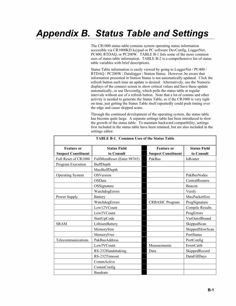
B-1
Appendix B. Status Table and Settings The CR1000 status table contains system operating status information accessible via CR1000KD keypad or PC software DevConfig, LoggerNet, PC400, RTDAQ, or PC200W. TABLE B-1 lists some of the more common uses of status table information. TABLE B-2 is a comprehensive list of status table variables with brief descriptions.
Status Table information is easily viewed by going to LoggerNet / PC400 / RTDAQ / PC200W | Datalogger | Station Status. However, be aware that information presented in Station Status is not automatically updated. Click the refresh button each time an update is desired. Alternatively, use the Numeric displays of the connect screen to show critical values and have these update automatically, or use Devconfig, which polls the status table at regular intervals without use of a refresh button. Note that a lot of comms and other activity is needed to generate the Status Table, so if the CR1000 is very tight on time, just getting the Status Table itself repeatedly could push timing over the edge and cause skipped scans.
Through the continued development of the operating system, the status table has become quite large. A separate settings table has been introduced to slow the growth of the status table. To maintain backward compatibility, settings first included in the status table have been retained, but are also included in the settings editor.
TABLE B-1. Common Uses of the Status Table
Feature or Status Field Feature or Status Field Suspect Constituent to Consult Suspect Constituent to Consult Full Reset of CR1000 FullMemReset (Enter 98765) PakBus IsRouter Program Execution BuffDepth MaxBuffDepth Operating System OSVersion PakBusNodes OSDate CentralRouters OSSignature Beacon WatchdogErrors Verify Power Supply Battery MaxPacketSize WatchdogErrors CRBASIC Program ProgSignature Low12VCount Compile Results Low5VCount ProgErrors StartUpCode VarOutofBound SRAM LithiumBattery SkippedScan MemorySize SkippedSlowScan MemoryFree PortStatus Telecommunications PakBusAddress PortConfig Low5VCount Measurements ErrorCalib RS-232Handshaking Data SkippedRecord RS-232Timeout DataFillDays CommActive CommConfig Baudrate

Appendix B. Status Table and Settings
B-2
TABLE B-2. Status Table Fields and Descriptions
Highlighted fields are also found in Settings
Status Table Fieldname Description Variable Type
Default Normal Range
User can change?
Info Type
Record Num Record number for this set of data _ _ _ TimeStamp Time the record was generated Time _ _ _ OSVersion Version of the Operating System String _ _ _ Status OSDate Date OS was released. String _ _ _ Status OSSignature Operating System Signature Integer _ _ _ Status SerialNumber CR1000 specific serial number. Stored
in FLASH memory. Integer _ _ _ Status
RevBoard Hardware revision number. Stored in FLASH memory.
Integer _ _ _ Status
StationName1 Name of the CR1000. Stored in FLASH memory.
String _ Yes Config
PakBusAddress2 CR1000 PakBus address. String 1 1 to 3999 Yes Config PB
ProgName Name of current (running) program. String _ _ _ Status StartTime Time the program began running. Time _ _ _ Status RunSignature Signature of the compiled binary data
structure for the current program. Value is independent of comments added or non-functional changes to the program. Often changes with operating system changes.
Integer _ _ _ Status
ProgSignature Signature of the current running program file including comments. Does not change with operating system changes.
Integer _ _ _ Status
Battery Current value of the battery voltage. Measurement is made in the background calibration.
Float _ 9.6-16 Volts
_ Measure
PanelTemp Current wiring panel temperature. Measurement is made in the background calibration.
Float _ _ _ Measure
WatchdogErrors3 Number of Watchdog errors that have occurred while running this program.
Integer 0 0 Can Reset = 0
Error
LithiumBattery4 Current voltage of the lithium battery. Measurement is updated in background calibration.
Float _ 2.7-3.6 Volts
_ Measure
Low12VCount5 Number of occurrences of the 12VLow signal being asserted. When this condition is detected, the CR1000 ceases measurements and goes into a low power mode until proper system voltage is restored.
Integer 0 0 Can Reset = 0
Error
Low5VCount Number of occurrences of the 5VExtLow signal being asserted.
Integer 0 0 Can Reset = 0
Error
CompileResults Contains error messages generated by compilation or during run time.
String _ 0 _ Error
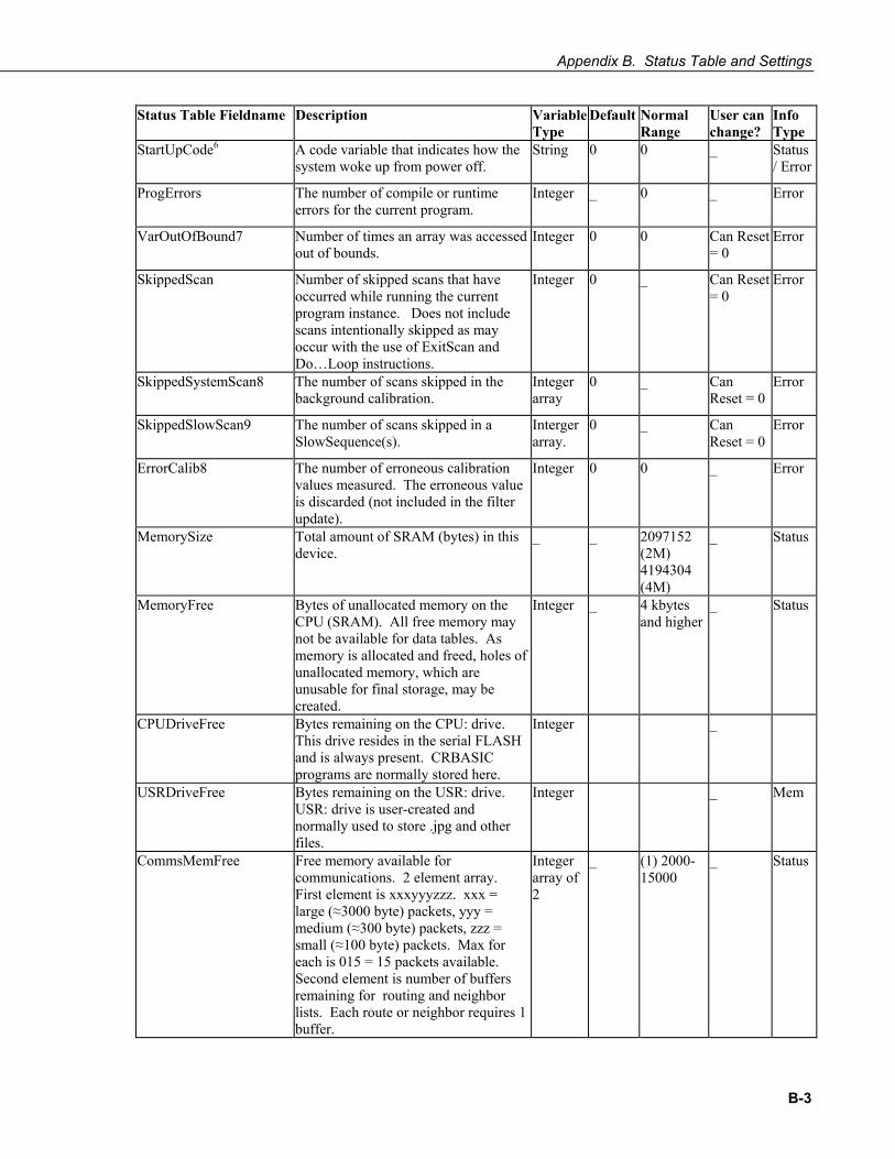
Appendix B. Status Table and Settings
B-3
Status Table Fieldname Description Variable Type
Default Normal Range
User can change?
Info Type
StartUpCode6 A code variable that indicates how the system woke up from power off.
String 0 0 _ Status / Error
ProgErrors The number of compile or runtime errors for the current program.
Integer _ 0 _ Error
VarOutOfBound7 Number of times an array was accessed out of bounds.
Integer 0 0 Can Reset = 0
Error
SkippedScan Number of skipped scans that have occurred while running the current program instance. Does not include scans intentionally skipped as may occur with the use of ExitScan and Do…Loop instructions.
Integer 0 _ Can Reset = 0
Error
SkippedSystemScan8 The number of scans skipped in the background calibration.
Integer array
0 _ Can Reset = 0
Error
SkippedSlowScan9 The number of scans skipped in a SlowSequence(s).
Interger array.
0 _ Can Reset = 0
Error
ErrorCalib8 The number of erroneous calibration values measured. The erroneous value is discarded (not included in the filter update).
Integer 0 0 _ Error
MemorySize Total amount of SRAM (bytes) in this device.
_ _ 2097152 (2M) 4194304 (4M)
_ Status
MemoryFree Bytes of unallocated memory on the CPU (SRAM). All free memory may not be available for data tables. As memory is allocated and freed, holes of unallocated memory, which are unusable for final storage, may be created.
Integer _ 4 kbytes and higher
_ Status
CPUDriveFree Bytes remaining on the CPU: drive. This drive resides in the serial FLASH and is always present. CRBASIC programs are normally stored here.
Integer _
USRDriveFree Bytes remaining on the USR: drive. USR: drive is user-created and normally used to store .jpg and other files.
Integer _ Mem
CommsMemFree Free memory available for communications. 2 element array. First element is xxxyyyzzz. xxx = large (≈3000 byte) packets, yyy = medium (≈300 byte) packets, zzz = small (≈100 byte) packets. Max for each is 015 = 15 packets available. Second element is number of buffers remaining for routing and neighbor lists. Each route or neighbor requires 1 buffer.
Integer array of 2
_ (1) 2000-15000
_ Status
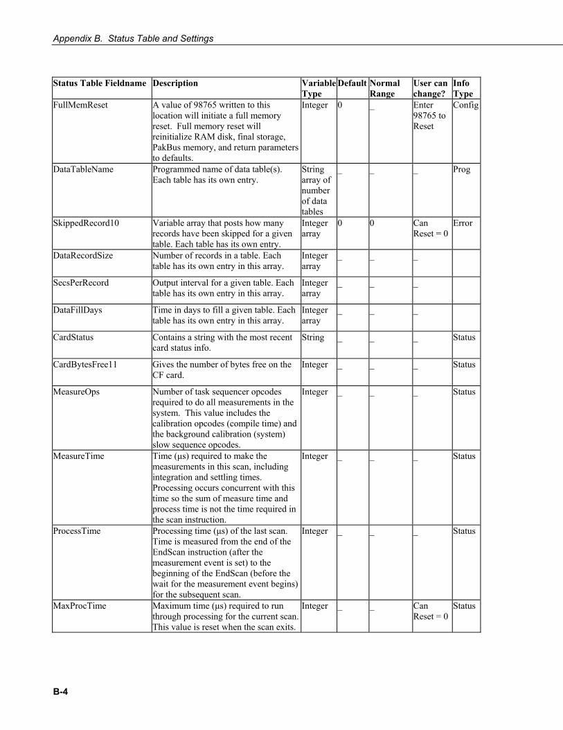
Appendix B. Status Table and Settings
B-4
Status Table Fieldname Description Variable
Type Default Normal
Range User can change?
Info Type
FullMemReset A value of 98765 written to this location will initiate a full memory reset. Full memory reset will reinitialize RAM disk, final storage, PakBus memory, and return parameters to defaults.
Integer 0 _ Enter 98765 to Reset
Config
DataTableName Programmed name of data table(s). Each table has its own entry.
String array of number of data tables
_ _ _ Prog
SkippedRecord10 Variable array that posts how many records have been skipped for a given table. Each table has its own entry.
Integer array
0 0 Can Reset = 0
Error
DataRecordSize Number of records in a table. Each table has its own entry in this array.
Integer array
_ _ _
SecsPerRecord Output interval for a given table. Each table has its own entry in this array.
Integer array
_ _ _
DataFillDays Time in days to fill a given table. Each table has its own entry in this array.
Integer array
_ _ _
CardStatus Contains a string with the most recent card status info.
String _ _ _ Status
CardBytesFree11 Gives the number of bytes free on the CF card.
Integer _ _ _ Status
MeasureOps Number of task sequencer opcodes required to do all measurements in the system. This value includes the calibration opcodes (compile time) and the background calibration (system) slow sequence opcodes.
Integer _ _ _ Status
MeasureTime Time (μs) required to make the measurements in this scan, including integration and settling times. Processing occurs concurrent with this time so the sum of measure time and process time is not the time required in the scan instruction.
Integer _ _ _ Status
ProcessTime Processing time (μs) of the last scan. Time is measured from the end of the EndScan instruction (after the measurement event is set) to the beginning of the EndScan (before the wait for the measurement event begins) for the subsequent scan.
Integer _ _ _ Status
MaxProcTime Maximum time (μs) required to run through processing for the current scan. This value is reset when the scan exits.
Integer _ _ Can Reset = 0
Status

Appendix B. Status Table and Settings
B-5
Status Table Fieldname Description Variable
Type Default Normal
Range User can change?
Info Type
BuffDepth Shows the current Pipeline Mode processing buffer depth., which indicates how far processing is currently behind measurement.
MaxBuffDepth Gives the maximum number of buffers processing lagged measurement.
LastSystemScan8 The last time the background calibration executed.
Integer array
_ _ _ Status
LastSlowScan9 The last time SlowSequence scan(s) executed.
Integer array
_ _ _ Status
SystemProcTime8,12 The time (μs) required to process the background calibration.
Integer array
_ _ _ Status
SlowProcTime9,12 The time (μs) required to process SlowSequence scan(s).
Integer array
_ _ _ Status
MaxSystemProcTime8,13 The maximum time (μs) required to process the background calibration.
Integer array
_ _ _ Status
MaxSlowProcTime9,13 The maximum time (μs) required to process SlowSequence scan(s).
Integer array
_ _ _ Status
PortStatus Array of Boolean values posting the state of control ports. Values updated every 500 ms.
Boolean array of 8
False True or False
Yes Status
PortConfig Array of strings explaining the use of the associated control port. Valid entries are: Input, Output, SDM, SDI-12, Tx, and Rx.
String array of 8
Input Input or Output
_ Status
SW12Volts Status of switched 12 V control port. Boolean False True or False
Yes Status
Security14 Array of the three security settings or codes. Will not be shown if security is enabled.
Integer array of 3
0, 0, 0 0 - 65535 (0 is no security)
Yes Status
RS-232Power (RS-232 Always On)
Controls whether the RS-232 port will remain active even when communication is not taking place. If RS-232 handshaking is enabled (handshaking buffer size is non-zero), this setting must be set to yes
Boolean 0 0 or 1 _
RS-232Handshaking (RS-232 Hardware Handshaking Buffer Size)
If non zero, hardware handshaking is active on the RS-232 port. This setting specifies the maximum packet size sent between checking for CTS.
Integer 0 _
RS-232Timeout (RS-232 Hardware Handshaking Timeout)
For RS-232 hardware handshaking, this specifies in tens of ms the timeout that the datalogger will wait between packets if CTS is not asserted.
Integer 0 _

Appendix B. Status Table and Settings
B-6
Status Table Fieldname Description Variable
Type Default Normal
Range User can change?
Info Type
CommActive15 Array of Boolean values telling if communications is currently active on the corresponding port. Aliased to CommActiveRS-232, CommActiveME, CommActiveCOM310, CommActiveSDC7, CommActiveSDC8, CommActiveSDC10 CommActiveSDC11 CommActiveCOM1, CommActiveCOM2, CommActiveCOM3, CommActiveCOM4
Boolean array of 9
False, except for the active COM
True or False
_ Status
CommConfig Array of values telling the configuration of comm ports. Aliased to CommConfigRS-232, CommConfigME, CommConfigCOM310, CommConfigSDC7, CommConfigSDC8, CommConfigSDC10 CommConfigSDC11 CommConfigCOM1, CommConfigCOM2, CommConfigCOM3, CommConfigCOM4
Integer array of 9
RS-232 through SDC8 = 4 (Enabled) COM1 through COM4 = 0 (Disabled)
0 = Program Disabled 4 = Program Enabled
Ports toggled through program control (SerialOpen / SerialClose). RS-232 is always hardware enabled.
Config
Baudrate16 Array of baudrates for comms. Aliased to: BaudrateRS-232, BaudrateME, BaudrateSDC BaudrateCOM1 BaudrateCOM2 BaudrateCOM3 BaudrateCOM4
Integer array of 9
RS-232=-115200 ME-SDC8 = 115200 COM1-4 = 0
0 = Auto 1200 2400 4800 9600 19.2k 38.4k 57.6k 115.2k
Yes, can also use SerialOut instruction to setup.
Config
IsRouter Is the CR1000 configured to act as router
Boolean False 0 or 1 Yes Config PB
PakBusNodes Number of nodes (approximately) that will exist in the PakBus network. This value is used to determine how much memory to allocate for networking.
Integer 50 >=50 Yes Config PB
CentralRouters(1) - (8)17 Array of (8) PakBus addresses for central routers.
Integer array of 8
0 _ Yes Config PB
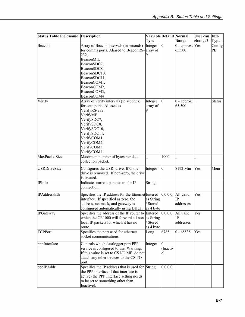
Appendix B. Status Table and Settings
B-7
Status Table Fieldname Description Variable
Type Default Normal
Range User can change?
Info Type
Beacon Array of Beacon intervals (in seconds) for comms ports. Aliased to BeaconRS-232, BeaconME, BeaconSDC7, BeaconSDC8, BeaconSDC10, BeaconSDC11, BeaconCOM1, BeaconCOM2, BeaconCOM3, BeaconCOM4
Integer array of 9
0 0 - approx. 65,500
Yes Config PB
Verify Array of verify intervals (in seconds) for com ports. Aliased to VerifyRS-232, VerifyME, VerifySDC7, VerifySDC8, VerifySDC10, VerifySDC11, VerifyCOM1, VerifyCOM2, VerifyCOM3, VerifyCOM4
Integer array of 9
0 0 - approx. 65,500
_ Status
MaxPacketSize Maximum number of bytes per data collection packet.
_ 1000 _ _
USRDriveSize Configures the USR: drive. If 0, the drive is removed. If non-zero, the drive is created.
Integer 0 8192 Min Yes Mem
IPInfo Indicates current parameters for IP connection.
String
IPAddressEth Specifies the IP address for the Etnernet interface. If specified as zero, the address, net mask, and gateway is configured automatically using DHCP.
Entered as String / Stored as 4 byte
0.0.0.0 All valid IP addresses
Yes
IPGateway Specifies the address of the IP router to which the CR1000 will forward all non-local IP packets for which it has no route.
Entered as String / Stored as 4 byte
0.0.0.0 All valid IP addresses
Yes
TCPPort Specifies the port used for ethernet socket communications.
Long 6785 0 - 65535 Yes
pppInterface Controls which datalogger port PPP service is configured to use. Warning: If this value is set to CS I/O ME, do not attach any other devices to the CS I/O port.
Integer 0 (Inactive)
pppIPAddr
Specifies the IP address that is used for the PPP interface if that interface is active (the PPP Interface setting needs to be set to something other than Inactive).
String 0.0.0.0

Appendix B. Status Table and Settings
B-8
Status Table Fieldname Description Variable Type
Default Normal Range
User can change?
Info Type
pppUsername Specifies the user name that is used to log in to the PPP server.
String _
pppPassword Specifies the password that is used to log in to the PPP server.
String _
pppDial Specifies the dial string that follows ATD (e.g., #777 for Redwing CDMA) or a list of AT commands separated by ';' (e.g., ATV1; AT+CGATT=0;ATD*99***1#), that are used to initialize and dial through a modem before a PPP connection is attempted. A blank string means that dialling is not necessary before a PPP connection is established.
String _
pppDialResponse Specifies the response expected after dialing a modem before a PPP connection can be established.
String connect _ Yes
Messages Contains a string of messages that can be entered by the user.
String _ Yes
CalGain18 Calibration table of Gain values. Each integration / range combination has a gain associated with it. These numbers are updated by the background slow sequence if needed in the program.
Float array of 18
_ . _ Calib
CalSeOffSet18 Calibration table of single ended offset values. Each integration / range combination has a single ended offset associated with it. These numbers are updated by the background slow sequence if needed in the program.
Integer array of 18
_ close to 0 _ Calib
CalDiffOffset18 Calibration table of differential offset values. Each integration / range combination has a differential offset associated with it. These numbers are updated by the background slow sequence if needed in the program.
Integer array of 18
_ close to 0 _ Calib
1 The StationName instruction can also be used in a program to write to this field. This is not the name used in the TOA data file header.
2 Pak Bus Addresses 1 to 4094 are valid. Addresses >= 4000 are generally used for a PC by PC200W, RTDAQ, PC400, or LoggerNet.
3 Watchdog errors are automatically reset upon compiling a new program.
4 Replace the lithium battery if <2.7V. See section 1.10.2 for replacement directions.
5 The 12V low comparator has some variation, but typically triggers at about 9.0 volts. The minimum specified input voltage of 9.6 V will not cause a 12 V low, but a 12 V low condition will stop the program

Appendix B. Status Table and Settings
B-9
execution before the CR1000 will give bad measurements due to low of supply voltage.
6 Currently not being used (12/1/2004)
7 The Variable out of Bounds error occurs when a program tries to write to an array variable outside of its declared size. It is a programming error that causes this, and should not be ignored. When the datalogger detects that a write outside of an array is being attempted it does not perform the write and increments the VOOB in the status table. The compiler and pre-compiler can only catch things like reps too large for an array etc. If an array is used in a loop or expression the pre-compiler does not (in most cases cannot) check to see if an array is accessed out of bounds (i.e. accessing an array with a variable index such as arr(index) = arr(index-1), where index is a variable).
8 The background calibration runs automatically in a hidden SlowSequence scan (Section 3.8.).
9 If no user entered SlowSequence scans are programmed, this variable does not appear. If multiple user entered SlowSequence scans programmed, this variable becomes an array with a value for each scan.
10 The order of tables is the order in which they are declared.
11 Card bytes free is shown = -1 when no card is present.
12 Displays a large number until a SlowSequence scan runs.
13 Displays 0 until a SlowSequence scan runs.
14 Security can be changed via DeviceConfig, CR1000KD, PBGraph, StatusTable, and SetSecurity instruction. Shows -1 if security code has not been given / deactivated.
15 When the SerialOpen instruction is used CommsConfig is loaded with the format parameter of that instruction. Currently (11/2004), the only formatting option available is 0 = No error checking. PakBus communication can occur concurrently on the same port If the port was previously opened (in the case of the CP UARTS) for PakBus, or if the port is always opened ( CS-9pin, and RS-232) for PakBus the code is 4.
16 The value shown is the initial baud rate the CR1000 will use. A negative value will allow the CR1000 to auto baud but will dictate at which baud rate to begin. Autobaud means to try different baud rates until successful or the operation times out.
17 A list of up to eight PB addresses for routers that can act as Central Routers. See CSI DevConfig (Device Configuration) software for more information.
18 (1) 5000 mV range 250 uS integration, (2) 2500 mV range 250 uS integration, (3) 250 mV range 250 uS integration, (4) 25 mV range 250 uS integration, (5) 7.5 mV range 250 uS integration, (6) 2.5 mV range 250 uS integration, (7) 5000 mV range 1/60 Hz integration, (8) 2500 mV range 1/60 Hz integration, (9) 250 mV range 1/60 Hz integration,

Appendix B. Status Table and Settings
B-10
(10) 25 mV range 1/60 Hz integration, (11) 7.5 mV range 1/60 Hz integration, (12) 2.5 mV range 1/60 Hz integration, (13) 5000 mV range 1/50 Hz integration, (14) 2500 mV range 1/50 Hz integration, (15) 250 mV range 1/50 Hz integration, (16) 25 mV range 1/50 Hz integration, (17) 7.5 mV range 1/50 Hz integration, (18) 2.5 mV range 1/50 Hz integration
TABLE B-3. Settings
Settings are accessed through Campbell Scientific’s Device Confituration Utility (DevConfig) for direct serial connection, or through PakBusGraph for most telecommunications options.
Setting Description Default Entry OS Version Specifies the version of the operating system currently
in the datalogger.
Serial Number Specifies the datalogger serial number assigned by the factory when the datalogger was calibrated.
Station Name Specifies a name assigned to this station. PakBus Address This setting specifies the PakBus address for this
device. The value for this setting must be chosen such that the address of the device is unique in the scope of the datalogger network. Duplication of PakBus addresses in two or more devices can lead to failures and unpredictable behavior in the PakBus network. The following values are the default addresses of various types of software and devices and should probably be avoided: LoggerNet 4094 PC400 4093 PC200 4092 Visual Weather 4091 RTDAQ 4090 DevConfig 4089 NL100 678 All other devices 1
1
Security Level 1 Specifies Level 1 Security. Zero disables all security. Range: 0 to 65535
0
Security Level 2 Specifies Level 2 Security. Zero disables levels 2 & 3. Range: 0 to 65535
0
Security Level 3 Specifies Level 3 Security. Zero disables level 3. Range: 0 to 65535
0
Is Router This setting controls whether the datalogger is configured as a router or as a leaf node. If the value of this setting is non-zero, the datalogger is configured to act as a PakBus router. That is, it is able to forward PakBus packets from one port to another. In order to perform its routing duties, a datalogger configured as a router will maintain its own list of neighbors and send this list to other routers in the PakBus network. It will also obtain and receive neighbor lists from other routers.
0
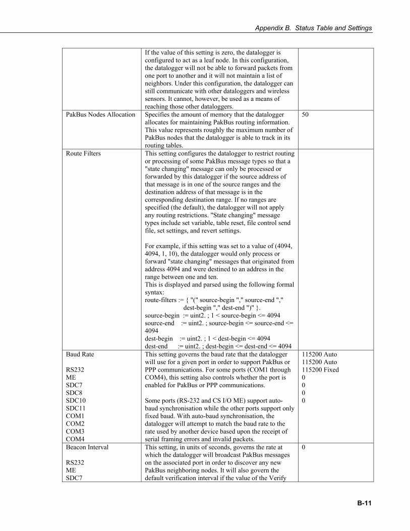
Appendix B. Status Table and Settings
B-11
If the value of this setting is zero, the datalogger is configured to act as a leaf node. In this configuration, the datalogger will not be able to forward packets from one port to another and it will not maintain a list of neighbors. Under this configuration, the datalogger can still communicate with other dataloggers and wireless sensors. It cannot, however, be used as a means of reaching those other dataloggers.
PakBus Nodes Allocation Specifies the amount of memory that the datalogger allocates for maintaining PakBus routing information. This value represents roughly the maximum number of PakBus nodes that the datalogger is able to track in its routing tables.
50
Route Filters This setting configures the datalogger to restrict routing or processing of some PakBus message types so that a "state changing" message can only be processed or forwarded by this datalogger if the source address of that message is in one of the source ranges and the destination address of that message is in the corresponding destination range. If no ranges are specified (the default), the datalogger will not apply any routing restrictions. "State changing" message types include set variable, table reset, file control send file, set settings, and revert settings. For example, if this setting was set to a value of (4094, 4094, 1, 10), the datalogger would only process or forward "state changing" messages that originated from address 4094 and were destined to an address in the range between one and ten. This is displayed and parsed using the following formal syntax: route-filters := "(" source-begin "," source-end "," dest-begin "," dest-end ")" . source-begin := uint2. ; 1 < source-begin <= 4094 source-end := uint2. ; source-begin <= source-end <= 4094 dest-begin := uint2. ; 1 < dest-begin <= 4094 dest-end := uint2. ; dest-begin <= dest-end <= 4094
Baud Rate RS232 ME SDC7 SDC8 SDC10 SDC11 COM1 COM2 COM3 COM4
This setting governs the baud rate that the datalogger will use for a given port in order to support PakBus or PPP communications. For some ports (COM1 through COM4), this setting also controls whether the port is enabled for PakBus or PPP communications. Some ports (RS-232 and CS I/O ME) support auto-baud synchronisation while the other ports support only fixed baud. With auto-baud synchronisation, the datalogger will attempt to match the baud rate to the rate used by another device based upon the receipt of serial framing errors and invalid packets.
115200 Auto 115200 Auto 115200 Fixed 0 0 0 0
Beacon Interval RS232 ME SDC7
This setting, in units of seconds, governs the rate at which the datalogger will broadcast PakBus messages on the associated port in order to discover any new PakBus neighboring nodes. It will also govern the default verification interval if the value of the Verify
0

Appendix B. Status Table and Settings
B-12
SDC8 SDC10 SDC11 COM1 COM2 COM3 COM4
Interval XXX setting for the associated port is zero.
Verify Interval RS232 ME SDC7 SDC8 SDC10 SDC11 COM1 COM2 COM3 COM4
This setting specifies the interval, in units of seconds, that is reported as the link verification interval in the PakBus hello transaction messages. It will indirectly govern the rate at which the datalogger will attempt to start a hello transaction with a neighbor if no other communication has taken place within the interval.
0
Neighbors Allowed RS232 ME SDC7 SDC8 SDC10 SDC11 COM1 COM2 COM3 COM4
This setting specifies, for a given port, the explicit list of PakBus node addresses that the datalogger will accept as neighbors. If the list is empty (the default value) any node is accepted as a neighbor. This setting will not effect the acceptance of a neighbor if that neighbor's address is greater than 3999. The formal syntax for this setting follows: neighbor := "(" range-begin "," range-end ")" . range-begin := pakbus-address. ; range-end := pakbus-address. pakbus-address := number. ; 0 < number < 4000 If more than 10 neighbors are in the allowed list and the beacon interval is 0, the beacon interval is changed to 60 seconds and beaconing is used for neighbor discovery instead of directed hello requests that consume comms memory.
Central Routers This setting specifies a list of up to eight PakBus addresses for routers that are able to work as Central Routers. By specifying a non-empty list for this setting, the datalogger is configured as a Branch Router meaning that it will not be required to keep track of neighbors of any routers except those in its own branch. Configured in this fashion, the datalogger will ignore any neighbor lists received from addresses in the central routers setting and will forward any messages that it receives to the nearest default router if it does not have the destination address for those messages in its routing table. Each entry in this list is expected to be formatted with a comma separating individual values.
Routes This read-only setting lists the routes in the case of a router, or the router neighbors in the case of a leaf node, that were known to the datalogger at the time the setting was read. Each route is represented by four
(1, 4089, 4089, 1000)

Appendix B. Status Table and Settings
B-13
components separated by commas and enclosed in parentheses: (port, via neighbor adr, pakbus adr, response time) Descriptions of components: Port Specifies a numeric code for the port the router will use:
Port Numeric Description Code
ComRS232 1 ComME 2 ComSDC6 (Com310) 3 ComSDC7 4 ComSDC8 5 ComSDC9 (Com320) 6 ComSDC10 7 ComSDC11 8 Com1 9 Com2 10 Com3 11 Com4 12 IP* 101,102,…
*If the value of the port number is ≥ 101, the connection is made through PakBus/TCP, either by the datalogger executing a TCPOpen() instruction or by having a connection made to the PakBus/TCP logger service. Via Neighbor Address Specifies address of neighbor/router to be used to send messages for this route. If the route is for a neighbor, this value is the same as the address. PakBus Address For a router, specifies the address the route reaches. If a leaf node, this is 0. Response Time For a router, specifies amount of time (in milli-seconds) that is allowed for the route. If a leaf node, this is 0.
USR: Drive Size Specifies the size in bytes allocated for the "USR:" ram disk drive.
0
Files Manager This setting specifies the number of files of a designated type that is saved when received from a specified node. There can be up to 4 such settings. The files are renamed by using the specified file name optionally altered by a serial number inserted before the file type. This serial number is used by the

Appendix B. Status Table and Settings
B-14
datalogger to know which file to delete after the serial number exceeds the specified number of files to retain. If the number of files is 0, then the serial number is not inserted. A special node id of 3210 can be used if the files are sent via FTP protocol or 3211 if the files are written via CRBasic. Note that this setting will operate only on files whose name is not a null string. Example: (129,CPU:NorthWest.JPG,2) (130,CRD:SouthEast.JPG,20) (130,CPU:Message.TXT,0) In the example above, *.JPG files from node 129 are named CPU:NorthWestnnn.JPG and 2 files are retained, and *.JPG files from node 130 are named CRD:SouthEastnnn.JPG, while 20 files are retained. The nnn serial number starts at 1 and will advance beyond 9 digits. In this example, all *.TXT files from node 130 is stored with the name CPU:Message.Txt, with no serial number inserted. FilesManager := "(" pakbus-address "," name-prefix "," number-files ")" . pakbus-address := number. ; 0 < number < 4095 name-prefix := string. number_files := number. ; 0 <= number < 10000000
Include File Name This setting specifies the name of a file to be implicitly included at the end of the current CRBasic program or can be run as the default program. This setting must specify both the name of the file to run as well as on the device (CPU:, USR:, or CRD:) on which the file is located. The extension of the file must also be valid for a datalogger program (.dld, .cr1 (CR1000), .cr3 (CR3000), or .cr8 (CR800 Series)). Consider the following example: CPU:pakbus_broker.dld The rules used by the datalogger when it starts are as follows: 1. If the logger is starting from power-up, any file that is marked as the run on power-up program is the "current program". Otherwise, any file that is marked as run now is selected. This behaviour has always been present and is not effected by this setting. 2. If there is a file specified by this setting, it is incorporated into the program selected above.

Appendix B. Status Table and Settings
B-15
3. If there is no current file selected or if the current file cannot be compiled, the datalogger will run the program given by this setting as the current program. 4. If the program run by this setting cannot be run or if no program is specified, the datalogger will attempt to run the program named default.cr1 on its CPU: drive. 5. If there is no default.cr1 file or if that file cannot be compiled, the datalogger will not run any program. The datalogger will now allow a SlowSequence statement to take the place of the BeginProg statement. This feature allows the specified file to act both as an include file and as the default program. The formal syntax for this setting follows: include-setting := device-name ":" file-name "." file-extension. device-name := "CPU" | "USR" | "CRD". File-extension := "dld" | "cr1" | "cr3" | "cr8".
Max Packet Size Specifies the maximum number of bytes per data collection packet.
1000
RS232 Always On Controls whether the RS-232 port will remain active even when communication is not taking place. Note that if RS232 handshaking is enabled (handshaking buffer size is non-zero), that this setting must be set to yes
No
RS232 Hardware Handshaking Buffer Size
If non zero, hardware handshaking is active on the RS232 port. This setting specifies the maximum packet size sent between checking for CTS.
0
RS232 Hardware Handshaking Timeout
For RS232 hardware handshaking, this specifies in tens of msecs the timeout that the datalogger will wait between packets if CTS is not asserted.
0
Ethernet IP Address Specifies the IP address for the Ethernet Interface. If specified as zero, the address, net mask, and gateway are configured automatically using DHCP.
0.0.0.0
Ethernet Subnet Mask Specifies the subnet mask for the Ethernet interface. 255.255.255.0 Default Gateway Specifies the address of the IP router to which the
datalogger will forward all non-local IP packets for which it has no route.
0.0.0.0
Name Servers This setting specifies the addresses of up to two domain name servers that the datalogger can use to resolve domain names to IP addresses. Note that if DHCP is used to resolve IP information, the addresses obtained via DHCP are appended to this list.
0.0.0.0 0.0.0.0
PPP Interface This setting controls which datalogger port PPP service is configured to use. Warning: If this value is set to CS I/O ME, you must not attach any other devices to the CS I/O port
Inactive

Appendix B. Status Table and Settings
B-16
PPP IP Address Specifies the IP address that is used for the PPP
interface if that interface is active (the PPP Interface setting needs to be set to something other than Inactive). The syntax for this setting is nnn.nnn.nnn.nnn. A value of 0.0.0.0 or an empty string will indicate that DHCP must be used to resolve this address as well as the subnet mask.
0.0.0.0
Reserved This field reserved. Do not edit. PPP User Name Specifies the user name that is used to log in to the PPP
server.
PPP Password Specifies the password that is used to log in to the PPP server when the PPP Interface setting is set to one of the client selections. Also specifies the password that must be provided by the PPP client when the PPP Interface setting is set to one of the server selections.
PPP Dial Specifies the dial string that would follow ATD (e.g., #777 for Redwing CDMA) or a list of AT commands seperated by ';' (e.g., ATV1;AT+CGATT=0;ATD*99***1#) that are used to initialise and dial through a modem before a PPP connection is attempted. A blank string indicates that no dialing will take place and will configure the datalogger to "listen" for PPP connections (basically to act as a server). A value of "PPP" will indicate to the datalogger that no modem dialing should take place but that it should PPP communication.
PPP Dial Response Specifies the response expected after dialing a modem before a PPP connection can be established.
CONNECT
PakBus/TCP Server Port This setting specifies the TCP service port for PakBus communications with the datalogger. Unless firewall issues exist, this setting probably does not need to be changed from its default value. This setting will be effective only if the PPP service is enabled using a PPP compatible network link.
6785
PakBus/TCP Client Connections
This setting specifies outgoing PakBus/TCP connections that the datalogger should maintain. Up to four addresses can be specified. An example specifying two connections follows: (192.168.4.203, 6785) (JOHN_DOE.server.com, 6785) The following is a formal syntax of the setting: TCP Connections := 4 address_pair . address_pair := "(" address "," tcp-port ")". address := domain-name | ip-address.

Appendix B. Status Table and Settings
B-17
PakBus/TCP Password Can be up to 31 characters in length. When active (not
blank), a log in process using an MD5 digest of a random number and this password must take place successfully before PakBus communications can proceed over an IP socket. The default setting is not active.
HTTP Server Port Configures the TCP port on which the HTTP (web server) service is offered. Generally the default value is sufficient unless a different value needs to be specified in order to accomodate port mapping rules in a network address translation firewall.
80
FTP Server Port Configures the TCP port on which the FTP service is offered. Generally the default value is sufficient unless a different value needs to be specified in order to accomodate port mapping rules in a network address translation firewall.
21
FTP User Name Specifies the user name that is used to log in to the FTP server. An empty string (the default) inactivates the FTP server.
anonymous
FTP Password Specifies the password that is used to log in to the FTP server.
*
Ping Enabled Set to one if the ICMP ping service should be enabled. This service is disabled by default.
1
FTP Enabled Set to one if the FTP service should be enabled. This service is disabled by default
1
Telnet Enabled Set to one if the Telnet service should be enabled. This service is disabled by default.
1
HTTP Enabled Set to one if the HTTP (web server) service should be enabled. This service is disabled by default.
1
IP Trace COM Port This setting specifies whether, and on what port TCP/IP trace information is sent. The type of information that is sent is controlled by the IP Trace Code setting.
Inactive
IP Trace Code This setting controls what type of information is sent on the port specified by IP Trace Port and via Telnet. Useful values are: 0 Trace is inactive 1 Startup and watchdog only 2 Verbose PPP 4 Print general informational messages 16 Display net interface error messages 256 Transport protocol (UDP/TCP/RVD) trace 8192 FTP trace 65535 Trace everything
0
TCP/IP Info Currently DHCP assigned addresses, Domain Name Servers, etc.
MAC: 00d02c042ccb eth IP: 192.168.1.99 eth mask: 255.255.240.0 eth gw: 192.168.2.19 dns svr1: 192.168.2.25 dns svr2: 192.168.2.16

Appendix B. Status Table and Settings
B-18

C-1
Appendix C. Serial Port Pin Outs C.1 CS I/O Communications Port
Pin configuration for the CR1000 CS I/O port is listed in TABLE C-1.
TABLE C-1. CS I/O Pin Description
ABR = Abbreviation for the function name. PIN = Pin number. O = Signal Out of the CR1000 to a peripheral. I = Signal Into the CR1000 from a peripheral.
PIN ABR I/O Description
1 5 V O 5V: Sources 5 VDC, used to power peripherals.
2 SG Signal Ground: Provides a power return for pin 1 (5V), and is used as a reference for voltage levels.
3 RING I Ring: Raised by a peripheral to put the CR1000 in the telecommunications mode.
4 RXD I Receive Data: Serial data transmitted by a peripheral are received on pin 4.
5 ME O Modem Enable: Raised when the CR1000 determines that a modem raised the ring line.
6 SDE O Synchronous Device Enable: Used to address Synchronous Devices (SDs), and can be used as an enable line for printers.
7 CLK/HS I/O Clock/Handshake: Used with the SDE and TXD lines to address and transfer data to SDs. When not used as a clock, pin 7 can be used as a handshake line (during printer output, high enables, low disables).
8 +12 VDC
9 TXD O Transmit Data: Serial data are transmitted from the CR1000 to peripherals on pin 9; logic low marking (0V) logic high spacing (5V) standard asynchronous ASCII, 8 data bits, no parity, 1 start bit, 1 stop bit, 300, 1200, 2400, 4800, 9600, 19,200, 38,400, 115,200 baud (user selectable).

Appendix C. Serial Port Pin Outs
C-2
C.2 RS-232 Communications Port C.2.1 Pin-Out
Pin configuration for the CR1000 RS-232 9-pin port is listed in TABLE C-2. Information for using a null modem with the RS-232 9-pin port is given in TABLE C-3.
The Datalogger RS-232 port can function as either a DCE (Data Communication Equipment) or DTE (Data Terminal Equipment) device. For the Datalogger RS-232 port to function as a DTE device, a null modem cable is required. The most common use of the Datalogger's RS-232 port is a connection to a computer DTE device. A standard DB9-to-DB9 cable can connect the computer DTE device to the Datalogger DCE device. The following table describes the Datalogger's RS-232 pin function with standard DCE naming notation. Note that pins 1, 4, 6 and 9 function differently than a standard DCE device, this is to accommodate a connection to a modem or other DCE device via a null modem.
TABLE C-2. Datalogger RS-232 Pin-Out
PIN = Pin number O = Signal Out of the CR1000 to a RS-232 device I = Signal Into the CR1000 from a RS-232 device X = Signal has no connection (floating)
PIN
DCE Function
Logger Function
I/O
Description
1 DCD DTR (tied to pin 6)
O* Data Terminal Ready
2 TXD TXD O Asynchronous data Transmit
3 RXD RXD I Asynchronous data Receive
4 DTR N/A X* Not Connected 5 GND GND GND Ground 6 DSR DTR O* Data Terminal Ready 7 CTS CTS I Clear to send 8 RTS RTS O Request to send 9 RI RI I* Ring
* Different pin function compared to a standard DCE device. These pins will accommodate a connection to modem or other DCE devices via a null modem cable.

Appendix C. Serial Port Pin Outs
C-3
C.2.2 Power States The RS-232 port is powered under the following conditions: 1) when the setting RS232Power is set or 2) when the SerialOpen for COMRS232 is used in the program. These conditions leave the RS-232 port on with no timeout. If SerialClose is used after SerialOpen then the port is powered down and left in a sleep mode waiting for characters to come in.
Under normal operation, the port is powered down waiting for input. Upon receiving input there is a 40 second software timeout before shutting down. The 40 second timeout is generally circumvented when communicating with LoggerNet / PC400 / RTDAQ / PC200W because it sends information as part of the protocol that lets the CR1000 know it can shut down the port.
When in sleep mode, hardware is configured to detect activity and wake up. Sleep mode has the penalty of losing the first character of the incoming data stream. PakBus takes this into consideration in the "ring packets" that are preceded with extra sync bytes at the start of the packet. SerialOpen leaves the interface powered up so no incoming bytes are lost.
When the logger has data to send via the RS-232 port, if the data are not a response to a received packet, such as sending a beacon, then it will power up the interface, send the data, and return to sleep mode with no 40 second timeout.
TABLE C-3. Standard Null Modem Cable or Adapter Pin Connections*
DB9 DB9 pin 1 & 6 ---------- pin 4 pin 2 ---------- pin 3 pin 3 ---------- pin 2 pin 4 ---------- pin 1 & pin 6 pin 5 ---------- pin 5 pin 7 ---------- pin 8 pin 8 ---------- pin 7 pin 9 XXXXX pin 9
(Most null modems have NO connection)
* If the null modem cable does not connect pin 9 to pin 9, then the modem will need to be configured to output a RING (or other characters previous to the DTR being asserted) on the modem’s TX line to wake the datalogger and activate the DTR line or enable the modem.

Appendix C. Serial Port Pin Outs
C-4
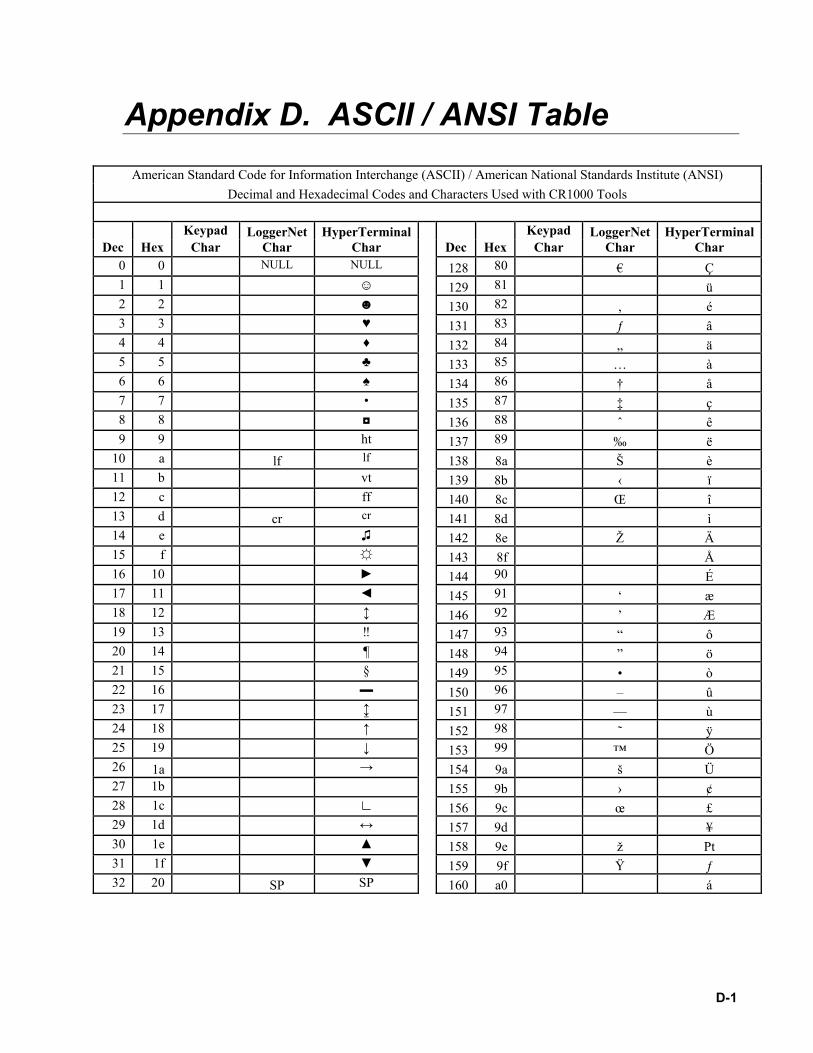
D-1
Appendix D. ASCII / ANSI Table
American Standard Code for Information Interchange (ASCII) / American National Standards Institute (ANSI) Decimal and Hexadecimal Codes and Characters Used with CR1000 Tools
Keypad LoggerNet HyperTerminal Keypad LoggerNet HyperTerminalDec Hex Char Char Char Dec Hex Char Char Char
0 0 NULL NULL 128 80 € Ç 1 1 129 81 ü 2 2 130 82 ‚ é 3 3 ♥ 131 83 ƒ â 4 4 ♦ 132 84 „ ä 5 5 ♣ 133 85 … à 6 6 ♠ 134 86 † å 7 7 • 135 87 ‡ ç 8 8 136 88 ˆ ê 9 9 ht 137 89 ‰ ë
10 a lf lf 138 8a Š è 11 b vt 139 8b ‹ ï 12 c ff 140 8c Œ î 13 d cr cr 141 8d ì 14 e 142 8e Ž Ä 15 f 143 8f Å 16 10 144 90 É 17 11 145 91 ‘ æ 18 12 146 92 ’ Æ 19 13 ‼ 147 93 “ ô 20 14 ¶ 148 94 ” ö 21 15 § 149 95 • ò 22 16 150 96 – û 23 17 151 97 — ù 24 18 ↑ 152 98 ˜ ÿ 25 19 ↓ 153 99 ™ Ö 26 1a → 154 9a š Ü 27 1b 155 9b › ¢ 28 1c ∟ 156 9c œ £ 29 1d ↔ 157 9d ¥ 30 1e 158 9e ž Pt 31 1f 159 9f Ÿ ƒ 32 20 SP SP 160 a0 á

Appendix D. ASCII / ANSI Table
D-2
Keypad LoggerNet HyperTerminal Keypad LoggerNet HyperTerminalDec Hex Char Char Char Dec Hex Char Char Char
33 21 ! ! ! 161 a1 ¡ í 34 22 " " " 162 a2 ¢ ó 35 23 # # # 163 a3 £ ú 36 24 $ $ $ 164 a4 ¤ ñ 37 25 % % % 165 a5 ¥ Ñ 38 26 & & & 166 a6 ¦ ª 39 27 ' ' ' 167 a7 § º 40 28 ( ( ( 168 a8 ¨ ¿ 41 29 ) ) ) 169 a9 © 42 2a * * * 170 aa ª ¬ 43 2b + + + 171 ab « ½ 44 2c , , , 172 ac ¬ ¼ 45 2d - - - 173 ad ¡ 46 2e . . . 174 ae ® « 47 2f / / / 175 af ¯ » 48 30 0 0 0 176 b0 ° 49 31 1 1 1 177 b1 ± 50 32 2 2 2 178 b2 ² 51 33 3 3 3 179 b3 ³ 52 34 4 4 4 180 b4 ´ 53 35 5 5 5 181 b5 µ 54 36 6 6 6 182 b6 ¶ 55 37 7 7 7 183 b7 · 56 38 8 8 8 184 b8 ¸ 57 39 9 9 9 185 b9 ¹ 58 3a : : : 186 ba º 59 3b ; ; ; 187 bb » 60 3c < < < 188 bc ¼ 61 3d = = = 189 bd ½ 62 3e > > > 190 be ¾ 63 3f ? ? ? 191 bf ¿ 64 40 @ @ @ 192 c0 À 65 41 A A A 193 c1 Á 66 42 B B B 194 c2 Â 67 43 C C C 195 c3 Ã 68 44 D D D 196 c4 Ä 69 45 E E E 197 c5 Å 70 46 F F F 198 c6 Æ 71 47 G G G 199 c7 Ç 72 48 H H H 200 c8 È 73 49 I I I
201 c9 É

Appendix D. ASCII / ANSI Table
D-3
Keypad LoggerNet HyperTerminal Keypad LoggerNet HyperTerminalDec Hex Char Char Char Dec Hex Char Char Char
74 4a J J J 202 ca Ê 75 4b K K K 203 cb Ë 76 4c L L L 204 cc Ì 77 4d M M M 205 cd Í 78 4e N N N 206 ce Î 79 4f O O O 207 cf Ï 80 50 P P P 208 d0 Ð 81 51 Q Q Q 209 d1 Ñ 82 52 R R R 210 d2 Ò 83 53 S S S 211 d3 Ó 84 54 T T T 212 d4 Ô 85 55 U U U 213 d5 Õ 86 56 V V V 214 d6 Ö 87 57 W W W 215 d7 × 88 58 X X X 216 d8 Ø 89 59 Y Y Y 217 d9 Ù 90 5a Z Z Z 218 da Ú 91 5b [ [ [ 219 db Û 92 5c \ \ \ 220 dc Ü 93 5d ] ] ] 221 dd Ý 94 5e ^ ^ ^ 222 de Þ 95 5f _ _ _ 223 df ß 96 60 ` ` ` 224 e0 à α 97 61 a a a 225 e1 á ß 98 62 b b b 226 e2 â Γ 99 63 c c c 227 e3 ã π
100 64 d d d 228 e4 ä Σ 101 65 e e e 229 e5 å σ 102 66 f f f 230 e6 æ µ 103 67 g g g 231 e7 ç τ 104 68 h h h 232 e8 è Φ 105 69 i i i 233 e9 é Θ 106 6a j j j 234 ea ê Ω 107 6b k k k 235 eb ë δ 108 6c l l l 236 ec ì ∞ 109 6d m m m 237 ed í φ 110 6e n n n 238 ee î ε 111 6f o o o 239 ef ï ∩ 112 70 p p p 240 f0 ð ≡ 113 71 q q q 241 f1 ñ ± 114 72 r r r
242 f2 ò ≥
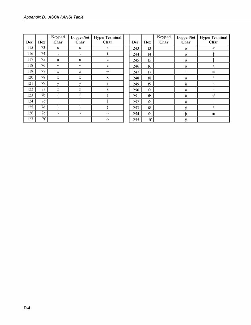
Appendix D. ASCII / ANSI Table
D-4
Keypad LoggerNet HyperTerminal Keypad LoggerNet HyperTerminalDec Hex Char Char Char Dec Hex Char Char Char 115 73 s s s 243 f3 ó ≤ 116 74 t t t 244 f4 ô ⌠ 117 75 u u u 245 f5 õ ⌡ 118 76 v v v 246 f6 ö ÷ 119 77 w w w 247 f7 ÷ ≈ 120 78 x x x 248 f8 ø ° 121 79 y y y 249 f9 ù · 122 7a z z z 250 fa ú · 123 7b 251 fb û √ 124 7c | | | 252 fc ü ⁿ 125 7d 253 fd ý ² 126 7e ~ ~ ~ 254 fe þ 127 7f
255 ff ÿ

E-1
Appendix E. FP2 Data Format FP2 data are two byte big endian values. The FP2 data format is nearly equivalent to the low resolution data format in older array based CSI dataloggers. Representing bits in each byte pair as ABCDEFGH IJKLMNOP, bits are described in Table E-1.
TABLE E-1. FP2 Data Format Bit Descriptions
Bit Description
A Polarity, 0 = +, 1 = -
B, C Decimal locators as defined in Table C-2
D - P 13 bit binary value, D being the MSB. Largest 13-bit magnitude is 8191, but CSI defines the largest allowable magnitude as 7999
Decimal locators can be viewed as a negative base 10 exponent with decimal locations as shown in Table E-2.
TABLE E-2. FP2 Decimal Locator Bits
B C Decimal Location
0 0 XXXX.
0 1 XXX.X
1 0 XX.XX
1 1 X.XXX

Appendix E. FP2 Data Format
E-2
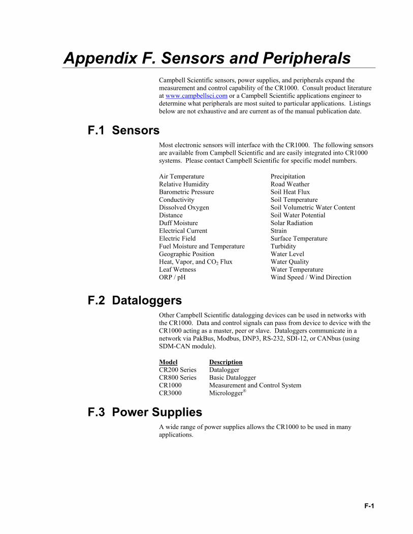
F-1
Appendix F. Sensors and Peripherals Campbell Scientific sensors, power supplies, and peripherals expand the measurement and control capability of the CR1000. Consult product literature at www.campbellsci.com or a Campbell Scientific applications engineer to determine what peripherals are most suited to particular applications. Listings below are not exhaustive and are current as of the manual publication date.
F.1 Sensors Most electronic sensors will interface with the CR1000. The following sensors are available from Campbell Scientific and are easily integrated into CR1000 systems. Please contact Campbell Scientific for specific model numbers.
Air Temperature Precipitation Relative Humidity Road Weather Barometric Pressure Soil Heat Flux Conductivity Soil Temperature Dissolved Oxygen Soil Volumetric Water Content Distance Soil Water Potential Duff Moisture Solar Radiation Electrical Current Strain Electric Field Surface Temperature Fuel Moisture and Temperature Turbidity Geographic Position Water Level Heat, Vapor, and CO2 Flux Water Quality Leaf Wetness Water Temperature ORP / pH Wind Speed / Wind Direction
F.2 Dataloggers Other Campbell Scientific datalogging devices can be used in networks with the CR1000. Data and control signals can pass from device to device with the CR1000 acting as a master, peer or slave. Dataloggers communicate in a network via PakBus, Modbus, DNP3, RS-232, SDI-12, or CANbus (using SDM-CAN module).
Model Description CR200 Series Datalogger CR800 Series Basic Datalogger CR1000 Measurement and Control System CR3000 Micrologger®
F.3 Power Supplies A wide range of power supplies allows the CR1000 to be used in many applications.

Appendix F. Sensors and Peripherals
F-2
F.3.1 Battery / Regulator Combination Read More! Information on matching power supplies to particular applications can be found in the Campbell Scientific Application Note “Power Supplies”, available at www.campbellsci.com.
Model Description PS100 12 Amp-Hour Rechargeable Battery & Regulator (requires
primary source). PS24 24 Amp-Hour Rechargeable Battery, Regulator and
Enclosure (requires primary source).
F.3.2 Batteries Model Description BPALK D-Cell 12 Volt Alkaline Battery Pack BP12 12 Amp-Hour Sealed Rechargeable Battery (requires
regulator & primary source). Includes mounting bracket for CSI enclosures.
BP24 24 Amp-Hour Sealed Rechargeable Battery (requires regulator & primary source). Includes mounting bracket for CSI enclosures.
F.3.3 Regulators Model Description CH100 12 Volt Charging Regulator (requires primary source)
F.3.4 Primary Sources Model Description 9591 18 Vac 1.2 Amp Wall Plug Charger (accepts 110 Vac mains
power, requires regulator) 14014 18 Vdc Wall Plug Charger (accepts 90-264 Vac mains
power, requires regulator) SP10 10-Watt Solar Panel (requires regulator) SP20 20-Watt Solar Panel (requires regulator) SP5-L 5-Watt Solar Panel (requires regulator) SP10R 10-Watt Solar Panel (includes regulator) SP20R 20-Watt Solar Panel (includes regulator) SP65 65-Watt Solar Panel (includes regulator)
F.4 Enclosures Model Description ENC10/12 10 inch x 12 inch Weather Tight Enclosure ENC12/14 12 inch x 14 inch Weather Tight Enclosure ENC14/16 14 inch x 16 inch Weather Tight Enclosure ENC16/18 16 inch x 18 inch Weather Tight Enclosure
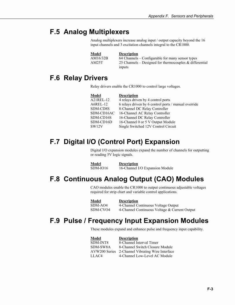
Appendix F. Sensors and Peripherals
F-3
F.5 Analog Multiplexers Analog multiplexers increase analog input / output capacity beyond the 16 input channels and 3 excitation channels integral to the CR1000.
Model Description AM16/32B 64 Channels – Configurable for many sensor types AM25T 25 Channels – Designed for thermocouples & differential
inputs
F.6 Relay Drivers Relay drivers enable the CR1000 to control large voltages.
Model Description A21REL-12 4 relays driven by 4 control ports A6REL-12 6 relays driven by 6 control ports / manual override SDM-CD8S 8-Channel DC Relay Controller SDM-CD16AC 16-Channel AC Relay Controller SDM-CD16S 16-Channel DC Relay Controller SDM-CD16D 16-Channel 0 or 5 V Output Module SW12V Single Switched 12V Control Circuit
F.7 Digital I/O (Control Port) Expansion Digital I/O expansion modules expand the number of channels for outputting or reading 5V logic signals.
Model Description SDM-IO16 16-Channel I/O Expansion Module
F.8 Continuous Analog Output (CAO) Modules CAO modules enable the CR1000 to output continuous adjustable voltages required for strip chart and variable control applications.
Model Description SDM-AO4 4-Channel Continuous Voltage Output SDM-CVO4 4-Channel Continuous Voltage & Current Output
F.9 Pulse / Frequency Input Expansion Modules These modules expand and enhance pulse and frequency input capability.
Model Description SDM-INT8 8-Channel Interval Timer SDM-SW8A 8-Channel Switch Closure Module AVW200 Series 2-Channel Vibrating Wire Interface LLAC4 4-Channel Low-Level AC Module
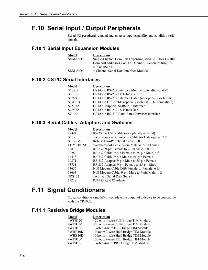
Appendix F. Sensors and Peripherals
F-4
F.10 Serial Input / Output Peripherals Serial I/O peripherals expand and enhance input capability and condition serial signals.
F.10.1 Serial Input Expansion Modules Model Description SDM-SIO1 Single-Channel Com Port Expansion Module. Uses CR1000
Com port addresses Com32 – Com46. Generates true RS-232 or RS485.
SDM-SIO4 4-Channel Serial Data Interface Module
F.10.2 CS I/O Serial Interfaces Model Description SC32B CS I/O to RS-232 Interface Module (optically isolated) SC105 CS I/O to RS-232 DCE Interface SC929 CS I/O to RS-232 Interface Cable (not optically isolated) SC-USB CS I/O to USB Cable (optically isolated, SDC compatible) SC532A CS I/O Peripheral to RS-232 Interface SC932A CS I/O to RS-232 DCE Interface SC100 CS I/O to RS-232 Baud Rate Converter Interface
F.10.3 Serial Cables, Adaptors and Switches Model Description 17394 RS-232 to USB Cable (not optically isolated) SC12 Two-Peripheral Connector Cable for Dataloggers, 2 ft SC12R-6 Robust Two-Peripheral Cable, 6 ft COMCBL2-L Weatherproof Cable, 9-pin Male to 9-pin Female 10873 RS-232, 9-pin Female to 9-Pin Male, 6 ft 7026 RS-232 Cable, 9-pin Female to 25-pin Male, 6 ft 14413 RS-232 Cable, 9-pin Male to 25-pin Female 10871 RS-232 Adapter, 9-pin Male to 25-pin Female 15751 RS-232 Adapter, 9-pin Female to 25-pin Male 13657 Null Modem Cable DB9 Female-to-Female, 6 ft 18663 Null Modem Cable, 9-pin Male to 9-pin Male, 1 ft SDS122 Two-way Serial Data Switch 17218 RJ45 to RS-232 Adapter
F.11 Signal Conditioners Signal conditioners modify or complete the output of a device to be compatible with the CR1000.
F.11.1 Resistive Bridge Modules Model Description 4WFB120 120 ohm 4-wire Full-Bridge TIM Module 4WFB350 350 ohm 4-wire Full-Bridge TIM Module 4WFB1K 1 kohm 4-wire Full-Bridge TIM Module 3WHB10K 10 kohm 3-wire Half-Bridge TIM Module 4WHB10K 10 kohm 4-wire Half-Bridge TIM Module 4WPB100 100 ohm 4-wire PRT Bridge TIM Module 4WPB1K 1 kohm 4-wire PRT Bridge TIM Module

Appendix F. Sensors and Peripherals
F-5
F.11.2 Voltage Dividers Model Description VDIV10:1 0:1 Voltage Divider VDIV2:1 2:1 Voltage Divider CVD20 6-Channel 20:1 Voltage Divider
F.11.3 Current Shunt Modules Model Description CURS100 100 ohm Current Shunt Module
F.12 Telecommunications Hardware Model Description RF400 100 mW spread spectrum radio modem CR206 100 mW spread spectrum radio enabled datalogger CR216 100 mW spread spectrum radio enabled datalogger
F.12.1 Router and Leaf Node Hardware TABLE F-1. PakBus Leaf Node and Router Device Configuration
Network Device Description
PakBus Leaf Node
PakBus Router
PakBus Aware Transparent
CR200 Datalogger •
CR800 Datalogger • •
CR1000 Datalogger • •
CR3000 Datalogger • •
CR5000 Datalogger • •
LoggerNet Software •
NL100 Network Link • •
NL115 Network Link •
MD485 Multidrop • •
RF401 Radio • • •
CC640 Camera •
SC105 Serial Interface •
SC32B Serial Interface •
SC932A Serial Interface •
COM220 Telephone Modem •
COM310 Telephone Modem •
SRM-5A Short-haul Modem •
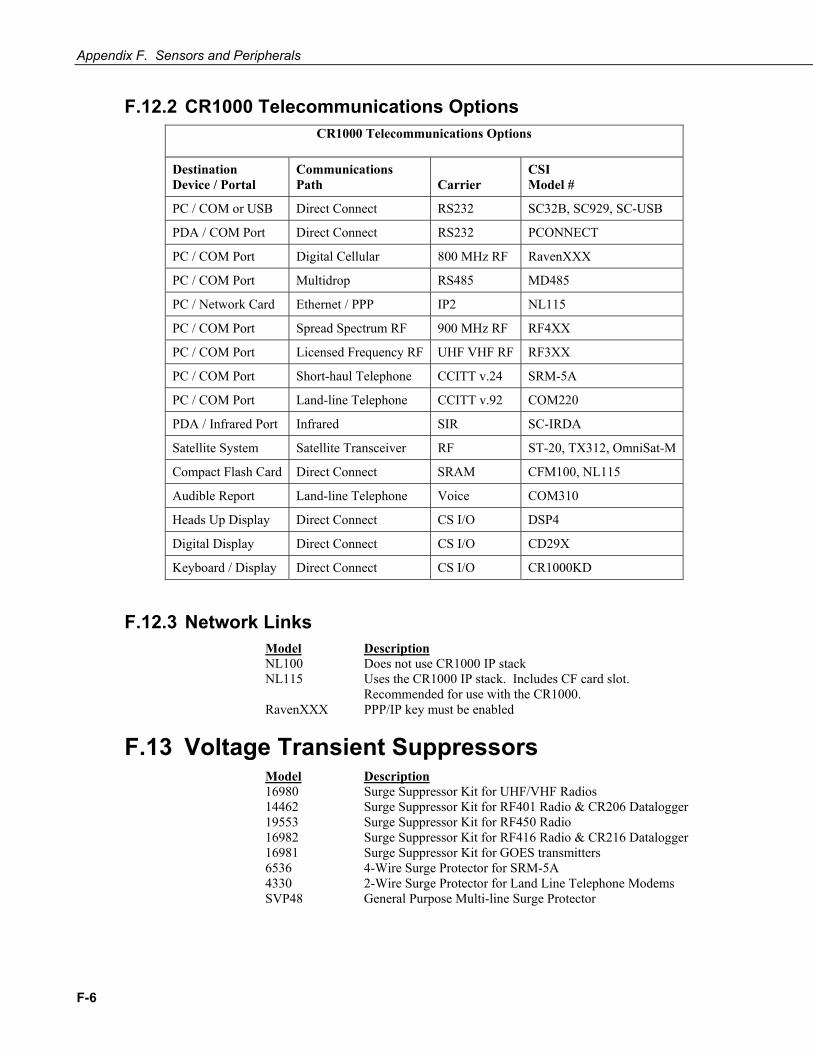
Appendix F. Sensors and Peripherals
F-6
F.12.2 CR1000 Telecommunications Options CR1000 Telecommunications Options
Destination Device / Portal
Communications Path Carrier
CSI Model #
PC / COM or USB Direct Connect RS232 SC32B, SC929, SC-USB
PDA / COM Port Direct Connect RS232 PCONNECT
PC / COM Port Digital Cellular 800 MHz RF RavenXXX
PC / COM Port Multidrop RS485 MD485
PC / Network Card Ethernet / PPP IP2 NL115
PC / COM Port Spread Spectrum RF 900 MHz RF RF4XX
PC / COM Port Licensed Frequency RF UHF VHF RF RF3XX
PC / COM Port Short-haul Telephone CCITT v.24 SRM-5A
PC / COM Port Land-line Telephone CCITT v.92 COM220
PDA / Infrared Port Infrared SIR SC-IRDA
Satellite System Satellite Transceiver RF ST-20, TX312, OmniSat-M
Compact Flash Card Direct Connect SRAM CFM100, NL115
Audible Report Land-line Telephone Voice COM310
Heads Up Display Direct Connect CS I/O DSP4
Digital Display Direct Connect CS I/O CD29X
Keyboard / Display Direct Connect CS I/O CR1000KD
F.12.3 Network Links Model Description NL100 Does not use CR1000 IP stack NL115 Uses the CR1000 IP stack. Includes CF card slot.
Recommended for use with the CR1000. RavenXXX PPP/IP key must be enabled
F.13 Voltage Transient Suppressors Model Description 16980 Surge Suppressor Kit for UHF/VHF Radios 14462 Surge Suppressor Kit for RF401 Radio & CR206 Datalogger 19553 Surge Suppressor Kit for RF450 Radio 16982 Surge Suppressor Kit for RF416 Radio & CR216 Datalogger 16981 Surge Suppressor Kit for GOES transmitters 6536 4-Wire Surge Protector for SRM-5A 4330 2-Wire Surge Protector for Land Line Telephone Modems SVP48 General Purpose Multi-line Surge Protector

Appendix F. Sensors and Peripherals
F-7
F.14 Card Storage Module Card storage modules attach to the CR1000 peripheral port. Use only industrial grade cards 2 gigabytes or smaller.
Model Description CFM100 CF card slot only NL115 Network Link with CF card slot
F.15 Camera Model Description CC640 Digital Camera

Appendix F. Sensors and Peripherals
F-8

Index-1
Index to Sections Information may be on pages subsequent to those listed in the index.
12 V Output, 3-5 12 Volt Supply, 4-1 5 V Output, 3-5 5 V Pin, C-1 5 V—Low, B-2 5 Volt Supply, 4-1 50 Hz, 6-1 50 Hz Rejection, 6-1 60 Hz, 6-1 60 Hz Rejection, 6-1 7999, 9-10 9-Pin Connectors, C-2 A/D, A-1 Abbreviations, 9-38 ABS, 10-22 AC, A-1 AC Excitation, 4-1, 4-8 AC Noise, 4-9, 4-11 AC Noise Rejection, 4-9 AC Sine Wave, 2-7, 4-33 Accuracy, 2-1, 4-26, A-1, A-10 ACOS, 10-21 AddPrecise, 10-25 Address, 14-1, 14-2, B-2 Address – SDI-12, 11-22 Address-- PakBus, B-10 Addressing Modbus, 15-7 Alias, 9-5, 9-7, 9-15, 9-29, 10-2 AM25T, 10-16 Amperage, 4-2 Amperes (Amps), A-1 Analog, 2-4, 3-2, A-1 Analog Control, 5-3 Analog Input, 2-4, 2-5 Analog Input Expansion, 5-1 Analog Input Range, 4-4 Analog Measurement, 19-3 Analog Output, 3-4, 5-3, 10-13 Analog Sensor, 4-36 AND, 10-19 AND Operator, 11-64 Anemometer, 2-7 AngleDegrees, 10-1 ANSI, A-1, D-1 Argos, 10-43 ArgosData, 10-43 ArgosDataRepeat, 10-43 ArgosError, 10-43 ArgosSetup, 10-43
ArgosTransmit, 10-43 Arithmetic, 9-31 Arithmetic Function, 10-22 Array, 9-7, 9-30 Arrays, 9-32 As, 10-2 ASCII, 10-26, A-1, D-1 ASIN, 10-21 Asynchronous, 11-44, A-1 Asynchronous Communication, 2-7 ATN, 10-21 ATN2, 10-21 Attributes, 12-9 Automatic Calibration, 4-6 Automatic Calibration Sequence, 9-23 Automobile Power, 6-2 AutoRange, 4-4, 4-5 Average, 10-4 AvgRun, 10-25 AvgSpa, 10-24 AVW200, 10-16 Background Calibration, 4-6, 4-8, 4-14, 9-23, B-5 Backup Battery, 2-2, 3-11, 18-2 Battery, 2-2, 3-6, 6-1, 10-10, 11-27, 18-2, 18-3,
19-7, B-2 Battery Backup, 2-2, 3-11 Battery Connection, 6-2 Baud, 2-10, 8-1, 10-32, 10-41, 19-5 Baud rate, 11-44 Baud Rate, 10-31, 10-42, 11-45, 15-4, A-1, B-6,
B-11 Beacon, 14-2, A-1, B-7, B-11 Beginner Software, 2-10, 2-11 BeginProg … EndProg, 10-7 Big Endian, 11-44 Binary, A-1 Binary Control, 5-2 Binary Format, 9-4 Bit Shift, 10-19 Bit Shift Operators, 10-18 Bit-shift Operators, 11-64 Bitwise Comparison, 11-64 Board Revision Number, B-2 Bool8, 9-11, 11-66, 11-67 BOOl8, A-2 BOOL8, 9-8, 9-10 Bool8 Data Type, 11-64 Boolean, 9-11, 9-32, 9-33, 19-4, A-1 Boolean data type, A-2

Index to Sections
Index-F-2
BOOLEAN Data Type, 9-8, 9-10 BrFull, 10-12 BrFull6W, 10-12 BrHalf, 10-12 BrHalf3W, 10-12 BrHalf4W, 10-12 Bridge, 2-6, 4-17, 4-19 Bridge – Quarter Bridge Shunt, 11-13 Bridge Measurement, 4-20, 10-12 Broadcast, 10-33, 14-2, 14-3 Buffer Depth, B-5 Buffer Size, 11-45 Burst Mode, 11-67 Byte Translation, 11-48 Cable Length, 4-11, 4-36 CAL Files, 11-1 CalFile, 10-36 Calibrate, 10-42, 10-44 Calibration, 3-11, 4-6, 4-14, 4-36, 9-23, 11-2 Calibration -- Background, B-5 Calibration – Field - Zero, 11-4 Calibration – Field Example, 11-3 Calibration – Field Offset, 11-5 Calibration – Field Slope / Offset, 11-7 Calibration – Field Two-Point, 11-3 Calibration – Field Calibration Slope Only, 11-9 Calibration Field, 11-1 Calibration Manual Field Calibration, 11-2 Calibration Single-Point Field Calibration, 11-3 Calibration-- Background, B-8 Calibration-- Background, B-8 Calibration-- Background, B-8 Calibration-- Error, B-3 Calibration Functions, 10-42 Call, 10-7 Callback, 10-41, 11-15, 13-2, A-2, A-4 CallTable, 10-7 Card Bytes Free, B-4 Card Status, B-4 CardOut, 10-4 Care, 3-11, 18-1 Ceiling, 10-22 CF, 12-10, A-2 CF Card, 8-4, 13-3, 17-10 Charging Circuit, 19-9, 19-10 CheckPort, 10-13 CheckSum, 10-26 CHR, 10-26 Circuit, 4-19, 4-35, 5-3 Clients, 16-3 CLK/HS Pin, C-1 Clock Function, 10-28 Clock Synchronization, 2-16 ClockChange, 10-28 ClockReport, 10-28, 10-33 ClockSet, 10-28
Closed Interval, 9-19 Code, A-2 Coil, 15-5 Collecting Data, 2-18 COM Port Connection, 2-9 Commands SDI-12, 11-22 Comment, 9-1 Comments, 9-1 Common Mode, 4-5 Common Mode Range, 7-4 Commonmode, 4-4 Common-mode Voltage, 4-2 Communication, 2-16, 3-8, 15-1, 19-5 Communications, 13-1 Communications Memory Free, B-3 Communications Ports, B-6 CompactFlash, 12-10, 17-10 CompactFlash Card, 8-4 Compile Program, 11-39 Compile Results, B-2 ComPortIsActive, 10-11 Concatenation, 11-71 Conditional Compilation, 11-39 Conditional Compile, 11-40 Conditioning Circuit, 4-35 Configuration, 8-1 Configure Display, 17-13 Connection, 2-2, 2-9, 3-2 Const, 9-13, 10-2 Constant, 9-7, 9-13, A-2 Constant Predefined, 9-13 Constant Conversion, 9-33 Constant Declaration, 10-2 ConstTable … EndConstTable, 10-3 Control, 2-8, 3-4, 4-2, 5-3, 10-7, 10-9, 11-61 Control I/O, A-2 Control Output Expansion, 5-1 Control Peripheral, 5-1 Control Port, 2-7 Control Ports, 4-33, B-5 Conversion, 9-33 Converting Program, 9-4 COS, 10-21 COSH, 10-21 Covariance, 10-4 CovSpa, 10-24 CPU, 12-4, A-2 CPU Drive Free, B-3 cr, 11-44 CR1000KD, 3-10, 11-35, 17-1, A-2 CR10X, 9-4, 9-19, A-2 CRBASIC Editor, 9-3 CRBASIC Program, 2-16 CRBASIC Programming, 9-1 CRD, 12-5, A-2 CS I/O, A-2, C-1

Index to Sections
Index-F-3
CS I/O Port, 3-5 CS110, 10-15 CS110Shutter, 10-15 CS616, 10-15 CS7500, 10-15 CSAT3, 10-15 Current, 4-2 Current Sourcing Limit, 4-2 Custom Display, 17-5 Custom Menu, 3-9, 3-10, 10-30 CVI, A-2 Data Collecting, 2-18 Data Monitoring, 2-17, 2-19 Data … Read … Restore, 10-9 Data Acquisition System, 3-1 Data Acquisition System Component, 2-1 Data Acquisition System Data Retrieval, 2-1 Data Acquisition System Datalogger, 2-1 Data Acquisition System Sensor, 2-1, 3-2 Data bits, 11-44 Data Collection, 2-1 Data Destination, 10-4 Data Fill Days, B-4 Data Format, 13-3, E-1 Data Point, A-2 Data Preservation, 12-9 Data Record Size, B-4 Data Retrieval, 2-1, 13-1, 13-3 Data Storage, 3-8, 9-18, 10-4, 12-1 Data Storage - Trigger, 11-60 Data Table, 2-17, 9-15, 9-16, 9-37, 10-3, 17-6 Data Table Access, 10-37 data table header, 9-35 Data Table Management, 10-37 Data Table Modifier, 10-3 Data Table Name, 9-7 Data Table Names, B-4 Data Tables, 11-74 Data Type, 9-8, 9-10, 9-32 Data Type Bool8, 11-64 Data Type NSEC, 11-61 Data Type Format, 11-45 Data Type-- LONG, A-5 Data Type-- NSEC, A-6 Data Types, 11-64 Data type—UINT2, A-9 DataEvent, 10-3 DataGram, 10-34 DataInterval, 10-3 DataInterval() Instruction, 9-18 Datalogger, 2-1 Datalogger Support Software, 3-12, A-2 DataLong … Read … Restore, 10-10 DataTable … EndTable, 10-3 DataTable() Instruction, 9-17 Date, 17-13
DaylightSaving, 10-28 DaylightSavingUS, 10-28 DC, A-2 DC Excitation, 4-1 DCE, 3-5, A-2, A-3, A-6 Debugging, 19-1 Declaration, 9-7, 9-15, 10-1 Declaration Data Table, 10-3 Declarations Modbus, 15-6 Default.CR1, 8-14 Delay, 10-7 Deployment, 8-7 Desiccant, 3-11, 18-1, A-2 DevConfig, 8-1, 8-2, A-3 Device Configuration, 8-1, 8-2 Device Map, 14-5 DewPoint, 10-23 DHCP, 11-20, A-3 Diagnosis – Power Supply, 19-7 Diagnostic, 10-10 Dial Sequence, 9-21 DialModem, 10-41 DialSequence … EndDialSequence, 10-34 DialVoice, 10-29 Differential, 2-4, 2-5, A-3 Digital, A-3 Digital I/O, 2-8, 3-2, 4-33, 10-13 Digital I/O Port, 2-7 Digital I/O Ports, 5-2 Digital Register, 15-5 Dim, 10-2, A-3 Dimension, 9-8, A-3 Diode OR Circuit, 6-2 Disable Variable, 9-19, 9-20, 11-59, 19-3 DisableVar, 11-59, 19-3 Display, 3-9, 17-1 Display Custom, 17-5 DisplayMenu … EndMenu, 10-30 DisplayValue, 10-31 DNP, 10-41, 15-2 DNP Variable, 15-2 DNP3, 15-1 DNP3, 3-9, 10-41 DNPUpdate, 10-41, 15-2 DNPVariable, 10-42 DNS, 11-21, A-3 Do … Loop, 10-7 Documentation, 9-1 Drive USR, B-7, B-13 DSP4, 10-4 DTE, 3-5, A-2, A-3, A-6 Duplex, 11-44 Durable Setting, 8-12 Earth Ground, 3-4, A-3 Earth Grounding, 7-1 Edge Timing, 2-7, 4-34

Index to Sections
Index-F-4
Edit File, 17-9 Edit Program, 17-9 Editor, 2-11 Editor – Short Cut, 9-3 Email, 10-39, 11-15 EMailRecv, 10-39 EMailSend, 10-39 EMF, 4-3 Enclosures, 18-1 Encrypt, 10-36 EndSequence, 10-7 Engineering Units, A-3 Environmental Enclosures, 18-1 Erase Memory, B-4 Error, 4-12, 4-23, 4-24, 4-25, 4-30, 19-3, 19-4, 19-6 Error – Analog Measurement, 7-5 Error – Soil Temperature Thermocouple, 7-6 Error Programming, 19-2, 19-3 Error Thermocouple, 4-22, 4-25, 4-26, 4-27, 4-28,
4-29 ESD, 3-4, A-3, A-10 ESD Protection, 7-1, 7-3 ESS, A-3 ESSInitialize, 10-6 ESSVariables, 10-2 Ethernet Settings, B-15 EthernetPower, 10-39 ETsz, 10-5 Evapotranspiration, 10-5 Example Program, 11-49, 11-54, 11-60 Excitation, 4-1, 10-13, A-3 Excitation Reversal, 4-7 ExciteV, 10-13 Execution, 9-21 Execution at Compile, 10-6 Execution Interval, 9-24, 9-25 Execution Time, A-3 Exit, 10-7 EXP, 10-22 Expression, 9-30, 9-31, 9-32, 9-33, 9-35, A-3 Expression Logical, 9-34 Expression String, 9-36 External Power Supply, 3-5 False, 9-35 FFT, 10-4 FFTSpa, 10-24 Field Calibration, 4-36, 11-1 FieldCal, 10-42, 11-3 FieldCal – Multiplier Only, 11-10 FieldCal - Zero, 11-5 FieldCal Multiplier, 11-8 FieldCal Offset, 11-6, 11-8 FieldCalStrain, 10-42, 11-11, 11-12 FieldNames, 10-4 File Attributes, 12-9 File Control, 12-7, A-3
File Display, 17-8 File Management, 10-36, 12-7 File Names, 12-14 FileClose, 10-36 FileEncrypt, 10-36 FileList, 10-36 FileManage, 10-36 FileMark, 10-37 FileOpen, 10-36 FileRead, 10-36 FileReadLine, 10-37 FileRename, 10-37 Files Manager, B-13 FileSize, 10-37 FileTime, 10-37 FileWrite, 10-37 Fill and Stop Memory, A-3 Fill-and-Stop, 12-1 FillStop, 10-3 Final Storage, A-4 Final Storage Table, 17-6 FindSpa, 10-35 Firmware, 3-6 FIX, 10-22 Fixed Voltage Range, 4-5 Flag, 9-12, 9-13 Flags, 15-6 Flat Map, 14-5 FLOAT, 9-8, 9-10, 9-32, 9-33, 9-34, 19-4, A-4 Floating Point, 9-31 Floor, 10-22 For ... Next, 10-8 Format - Numerical, 9-4 FormatFloat, 10-26 Forward, 1-1 FP2, 9-8, 9-10, 9-11, A-4, E-1 FRAC, 10-22 Frequency, 2-7, 4-30, 4-32, 4-33 FTP, A-4 FTP Client, 11-19 FTP Server, 11-19 FTP Settings, B-17 FTPClient, 10-39 Full Bridge, 2-6, 4-17 Full Duplex, A-4 Full Memory Reset, B-4, B-16 Function Codes Modbus, 15-7 Gain, 9-30 Garbage, A-4 Gas-discharge Tubes, 7-1 GetDataRecord, 10-34 GetRecord, 10-38 GetVariables, 10-34 global variable, A-4 Glossary, A-1 Glossary Modbus, 15-5

Index to Sections
Index-F-5
GOES, 10-43 GOESData, 10-43 GOESGPS, 10-43 GOESSetup, 10-43 GOESStatus, 10-43 GPS, 10-15 Gradient, 4-24, 4-25 Ground, 3-4, A-4 Ground Loop, 7-6 Ground Potential Error, 7-5 Ground Reference Offset, 4-8 Grounding, 3-11, 7-1, 7-2, 7-3, 7-4 Gypsum Block, 4-8 Half Bridge, 2-6, 4-17 Half Duplex, A-4 Handshake, Handshaking, A-4 Hello Exchange, A-4 Hello-message, 14-2 Hello-request, 14-3 Hertz, A-4 HEX, 10-26 Hexadecimal, 9-4 HexToDec, 10-26 High-frequency, 4-32, 4-33 Histogram, 10-6 Histogram4D, 10-6 Holding Register, 15-6 HTML, 11-17, A-4 HTTP, 11-16, A-4 HTTP Settings, B-17 HTTPOut, 10-39 Humidity, 3-11, 18-1 HydraProbe, 10-15 I/O Port, 2-7 ID, 8-4 IEEE4, 9-8, 9-10, 9-11, A-4 If ... Then ... Else … ElseIf ... EndIf, 10-8 IfTime, 10-28 IIF, 10-20 IMP, 10-20 Include, 10-37 Include File, 8-12, B-14 INF, 19-3, A-4 Infinite, 19-3 Information Services, 10-39, 11-15 Initiate telecommunication, A-4 Initiate Telecommunications, 10-41, 11-15, 13-2 INMARSAT-C, 10-44 Input Channel, 2-4, 2-5 Input Expansion Module, 2-9 Input Range, 4-4 Input Register, 15-6 Input Reversal, 4-7 Input/Output Instructions, A-5 INSATData, 10-44 INSATSetup, 10-44
INSATStatus, 10-44 Installation, 2-2 InStr, 10-26 Instruction, 9-28 Instructions
ABS, 10-22 ACOS, 10-21 AddPrecise, 10-25 Alias, 10-2 AM25T, 10-16 AND, 10-19 AngleDegrees, 10-1 ArgosData, 10-43 ArgosDataRepeat, 10-43 ArgosError, 10-43 ArgosSetup, 10-43 ArgosTransmit, 10-43 As, 10-2 ASCII, 10-26 ASIN, 10-21 ATN, 10-21 ATN2, 10-21 Average, 10-4 AvgRun, 10-25 AvgSpa, 10-24 AVW200, 10-16 Battery, 10-10 BeginProg … EndProg, 10-7 BrFull, 10-12 BrFull6W, 10-12 BrHalf, 10-12 BrHalf3W, 10-12 BrHalf4W, 10-12 Broadcast, 10-33 CalFile, 10-36 Calibrate, 10-42, 10-44 Call, 10-7 CallTable, 10-7 CardOut, 10-4 Ceiling, 10-22 CheckPort, 10-13 CheckSum, 10-26 CHR, 10-26 ClockChange, 10-28 ClockReport, 10-28, 10-33 ClockSet, 10-28 ComPortIsActive, 10-11 Const, 10-2 ConstTable … EndConstTable, 10-3 COS, 10-21 COSH, 10-21 Covariance, 10-4 CovSpa, 10-24 CS110, 10-15 CS110Shutter, 10-15 CS616, 10-15

Index to Sections
Index-F-6
CS7500, 10-15 CSAT3, 10-15 Data … Read … Restore, 10-9 DataEvent, 10-3 DataGram, 10-34 DataInterval, 10-3 DataLong … Read … Restore, 10-10 DataTable … EndTable, 10-3 DaylightSaving, 10-28 DaylightSavingUS, 10-28 Delay, 10-7 DewPoint, 10-23 DialModem, 10-41 DialSequence … EndDialSequence, 10-34 DialVoice, 10-29 Dim, 10-2 DisplayMenu … EndMenu, 10-30 DisplayValue, 10-31 DNP, 10-41 DNPUpdate, 10-41 DNPVariable, 10-42 Do … Loop, 10-7 DSP4, 10-4 EMailRecv, 10-39 EMailSend, 10-39 EndSequence, 10-7 ESSInitialize, 10-6 ESSVariables, 10-2 EthernetPower, 10-39 ETsz, 10-5 ExciteV, 10-13 Exit, 10-7 EXP, 10-22 FFT, 10-4 FFTSpa, 10-24 FieldCal, 10-42 FieldCalStrain, 10-42 FieldNames, 10-4 FileClose, 10-36 FileEncrypt, 10-36 FileList, 10-36 FileManage, 10-36 FileMark, 10-37 FileOpen, 10-36 FileRead, 10-36 FileReadLine, 10-37 FileRename, 10-37 FileSize, 10-37 FileTime, 10-37 FileWrite, 10-37 FillStop, 10-3 FindSpa, 10-35 FIX, 10-22 Floor, 10-22 For ... Next, 10-8 FormatFloat, 10-26
FRAC, 10-22 FTPClient, 10-39 GetDataRecord, 10-34 GetRecord, 10-38 GetVariables, 10-34 GOESData, 10-43 GOESGPS, 10-43 GOESSetup, 10-43 GOESStatus, 10-43 GPS, 10-15 HEX, 10-26 HexToDec, 10-26 Histogram, 10-6 Histogram4D, 10-6 HTTPOut, 10-39 HydraProbe, 10-15 If ... Then ... Else … ElseIf ... EndIf, 10-8 IfTime, 10-28 IIF, 10-20 IMP, 10-20 Include, 10-37 INSATData, 10-44 INSATSetup, 10-44 INSATStatus, 10-44 InStr, 10-26 InstructionTimes, 10-11 INT, 10-22 INTDV, 10-22 IPTrace, 10-39 Left, 10-26 Len, 10-26 LevelCrossing, 10-6 LN or LOG, 10-22 LoadFieldCal, 10-42 LOG10, 10-22 LowerCase, 10-27 LTrim, 10-26 Maximum, 10-4 MaxSpa, 10-24 Median, 10-4 MemoryTest, 10-11 MenuItem, 10-30 MenuPick, 10-30 Mid, 10-27 Minimum, 10-5 MinSpa, 10-24 MOD, 10-23 ModBusMaster, 10-41 ModBusSlave, 10-41 ModemHangup, 10-41 Moment, 10-5 Move, 10-36 MoveBytes, 10-31 MovePrecise, 10-6 MuxSelect, 10-16 Network, 10-34

Index to Sections
Index-F-7
NetworkTimeProtocol, 10-40 NewFieldCal, 10-42 NewFieldNames, 10-2 NewFile, 10-37 NOT, 10-19 OmniSatData, 10-44 OmniSatRandomSetup, 10-44 OmniSatStatus, 10-44 OmniSatSTSetup, 10-44 OpenInterval, 10-3 OR, 10-19 PakBusClock, 10-28, 10-34 PanelTemp, 10-11 PeakValley, 10-5 PeriodAvg, 10-13 PingIP, 10-40 PipelineMode, 10-1 PortGet, 10-13 PortsConfig, 10-13 PortSet, 10-13 PPPClose, 10-40 PPPOpen, 10-40 PreserveVariables, 10-2 PRT, 10-23 Public, 10-2 PulseCount, 10-13 PulseCountReset, 10-6 PulsePort, 10-14 PWM, 10-14 PWR, 10-23 RainFlow, 10-6 Randomize, 10-25 Read, 10-10 ReadIO, 10-14 RealTime, 10-11, 10-28 RectPolar, 10-23 Replace, 10-27 ResetTable, 10-38 Restore, 10-10 Right, 10-27 RMSSpa, 10-24 RND, 10-25 Round, 10-23 Route, 10-34 Routes, 10-35 RTrim, 10-27 RunProgram, 10-37 Sample, 10-5 SampleFieldCal, 10-5, 10-42 SampleMaxMin, 10-5 SatVP, 10-23 Scan … ExitScan … NextScan, 10-8 SDI12Recorder, 10-14 SDI12SensorResponse, 10-14 SDI12SensorSetup, 10-14 SDMAO4, 10-16
SDMCAN, 10-16 SDMCD16AC, 10-16 SDMCVO4, 10-16 SDMINT8, 10-16 SDMIO16, 10-17 SDMSIO4, 10-17 SDMSpeed, 10-17 SDMSW8A, 10-17 SDMTrigger, 10-17 SDMX50, 10-17 SecsSince1990, 10-29 Select Case … Case … Case Is … Case Else …
EndSelect, 10-8 SemaphoreGet, 10-10 SemaphoreRelease, 10-10 SendData, 10-35 SendFile, 10-34, 10-35 SendGetVariables, 10-35 SendTableDef, 10-35 SendVariables, 10-35 SequentialMode, 10-1 SerialBrk, 10-31 SerialClose, 10-31 SerialFlush, 10-31 SerialIn, 10-31 SerialInBlock, 10-31 SerialInChk, 10-32 SerialInRecord, 10-32 SerialOpen, 10-32 SerialOut, 10-32 SerialOutBlock, 10-32 SetStatus, 10-38 SGN, 10-23 ShutDownBegin, 10-10 ShutDownEnd, 10-10 Signature, 10-11 SIN, 10-21 SINH, 10-21 Slow Sequence, 10-9 SortSpa, 10-24 SplitStr, 10-27 Sqr, 10-23 StaticRoute, 10-35 Station Name, 10-1 StdDev, 10-5 StdDevSpa, 10-24 StrainCalc, 10-23 StrComp, 10-27 Sub, Exit Sub, End Sub, 10-1 SubMenu … EndSubMenu, 10-31 SubScan … NextSubScan, 10-9 SW12, 10-13 TableFile, 10-4 TableName.EventCount, 10-38 TableName.FieldName, 10-38 TableName.Output, 10-38

Index to Sections
Index-F-8
TableName.Record, 10-38 TableName.TableFull, 10-38 TableName.TableSize, 10-38 TableName.TimeStamp, 10-38 TAN, 10-21 TANH, 10-21 TCDiff, 10-12 TCPClose, 10-40 TCPOpen, 10-40 TCSE, 10-12 TDR100, 10-17 TGA, 10-15 Therm107, 10-15 Therm108, 10-15 Therm109, 10-16 TimedControl, 10-17 TimeIntoInterval, 10-29 Timer, 10-29 TimerIO, 10-14 TimeUntilTransmit, 10-35 Totalize, 10-5 Trim, 10-27 UDPDataGram, 10-40 UDPOpen, 10-40 Units, 10-2 UpperCase, 10-27 VaporPressure, 10-24 VibratingWire, 10-14 VoiceBeg, EndVoice, 10-29 VoiceHangup, 10-29 VoiceKey, 10-29 VoiceNumber, 10-29 VoicePhrases, 10-30 VoiceSetup, 10-30 VoiceSpeak, 10-30 VoltDiff, 10-11 VoltSE, 10-11 WaitDigTrig, 10-9 WebPageBegin / WebPageEnd, 10-2 WebPageBegin … WebPageEnd, 10-40 WetDryBulb, 10-24 While…Wend, 10-9 WindVector, 10-5 WorstCase, 10-39 WriteIO, 10-14 XOR, 10-20
InstructionTimes, 10-11 INT, 10-22 INTDV, 10-22 Integer, 9-33, A-5 Integrated Processing, 10-23 Integration, 4-9 Intermediate Memory, 9-19 Intermediate Storage, A-5 Internal Battery, 2-2, 3-11, 18-2 Interrupt, 2-7
Interval Timing, 4-34 Introduction, 1-1 Inverse Format Registers Modbus, 15-7 Ionic Sensor, 7-6 IP, 11-15, 11-20, A-5, B-7 IP Modbus, 15-8 IP Address, A-5, B-7, B-15, B-16 IP Gateway, B-7 IP Information, B-17 IPTrace, 10-39 IS, 10-39 Junction Box, 4-30 Keyboard, 3-9 Keyboard / Display, 11-35 Keyboard Display, 3-9, 3-10, 10-30, 17-1 LAN PakBus, 14-6 Lapse, 9-18 Lead, 4-11 Lead Length, 4-36 Leaf Node, 14-2, F-5 Leaf Nodes, 14-1 Left, 10-26 Len, 10-26 LevelCrossing, 10-6 lf, 11-44 Lightning, 2-2, 3-11, 7-1, A-3 Lightning Protection, 7-3 Lightning Rod, 7-3 Linear Sensor, 4-36 Link Performance, 14-5 Lithium Battery, 18-2, B-2 Little Endian, 11-44 LN or LOG, 10-22 LoadFieldCal, 10-42 local variable, A-5 LOG10, 10-22 Logger Control, 8-10 LoggerNet, 16-2, 16-3 Logic, 9-35 Logical Expression, 9-34 Logical Operator, 10-19 Long, 19-4 LONG, 9-8, 9-10, 9-11, 9-32, 9-33, 9-34, A-5 Long Lead, 4-11 Loop, A-5 Loop Counter, A-5 Low 12 V Counter, B-2 LowerCase, 10-27 Low-Level AC, 4-33 Low-level AC Input Module, 5-4 LSB, 11-44 LTrim, 10-26 Maintenance, 3-11, 18-1 Manage Files, B-13 Manual Organization, 1-1 Manually Initiated, A-5

Index to Sections
Index-F-9
Marks and Spaces, 11-44 Math, 9-32, 10-18, 19-4 Mathematical Operation, 9-32 Mathematical Operator, 10-18 Maximum, 10-4 MaxSpa, 10-24 MD5 digest, A-5 ME Pin, C-1 MeasOff, 4-6 Measurement Sequence, 4-4 Measurement Timing, 4-4 Measurement Error, 4-12 Measurement Instruction, 9-28, 10-10 Measurement Op Codes, B-4 Measurement Peripheral, 5-1 Measurement Time, B-4 Median, 10-4 Memory, 3-8, 9-32, 12-1 Memory Conservation, 9-18, 9-32, 11-48, 12-6 Memory-- Free, B-3 Memory Reset, 12-6 Memory-- Size, B-3 MemoryTest, 10-11 Menu Custom, 10-30, 11-35 MenuItem, 10-30 MenuPick, 10-30 Messages, B-8 Mid, 10-27 Milli, A-5 Millivoltage Measurement, 4-2 Minimum, 10-5 MinSpa, 10-24 MOD, 10-23 Modbus, 3-9, 10-41, 11-20, 15-4, 15-5, 15-6, A-5 ModbusMaster, 15-7 ModBusMaster, 10-41 ModbusSlave, 15-7 ModBusSlave, 10-41 Modem Control, 10-41 Modem Hangup Sequence, 9-21 Modem/Terminal, A-5 ModemHangup, 10-41 Moisture, 3-11, 18-1 Moment, 10-5 Monitoring Data, 2-17, 2-19 Mounting, 2-2 Move, 10-36 MoveBytes, 10-31, 15-7 MovePrecise, 10-6 MSB, 11-44 Multi-meter, A-5 Multiplexers, 5-1 Multiplier, 9-30 MuxSelect, 10-16 mV, A-5 Names, 9-29
NAN, 4-5, 7-4, 9-10, 19-3, A-5 Neighbor, 14-2 Neighbor Device, A-5 Neighbor Filter, 14-3 Neighbors, B-12 Network, 10-34 NetworkTimeProtocol, 10-40 NewFieldCal, 10-42 NewFieldNames, 10-2 NewFile, 10-37 NIST, A-5 Node, A-6 Nodes, 14-1 Noise, 4-3, 4-9, 4-11, 4-27, 6-1 Nominal Power, 3-6 NOT, 10-19 Not-a-number, 19-3 NSEC, 9-8, 9-10, 9-12, A-6 NSEC Data Type, 11-61 Null-modem, A-2, A-3, A-6 Numerical Format, 9-4 Offset, 4-8, 9-30 Ohm, A-6 Ohms Law, A-6 OID, 4-5 OMNISAT, 10-44 OmniSatData, 10-44 OmniSatRandomSetup, 10-44 OmniSatStatus, 10-44 OmniSatSTSetup, 10-44 On-line Data Transfer, A-6 Op Codes, B-4 Open Input Detect, 4-5 Open Inputs, 4-5 OpenInterval, 9-19, 10-3 Operating System, 8-2, 8-3, B-10 Operating Temperature Range, 18-1 Operator, 10-18, 10-19 Operators – Bit Shift, 10-18 OR, 10-19 OR Diode Circuit, 6-2 OR Operator, 11-64 OS, 8-2, 8-3 OS Date, B-2 OS Signature, B-2 OS Version, B-2 Output, A-6 Output Array, A-6 Output Interval, A-6 Output Processing, 9-19, 10-4 Output Processing Instructions, A-6 Output Trigger, 11-59 OutputOpt, 11-30 Overrun, 19-1, B-3 Overview, 3-1 Overview – Power Supply, 19-6

Index to Sections
Index-F-10
Overview Modbus, 15-4 Packet Size, B-7, B-15 PakBus, 3-8, 10-32, 10-33, 14-5, A-6, F-5 PakBus Address, B-2, B-10 PakBus Information, B-16, B-17 PakBus LAN, 14-6 PakBus Network, 14-2 PakBus Nodes, B-6, B-11 PakBus Overview, 14-1 PakBusClock, 10-28, 10-34 Panel Temperature, 4-23, 4-24, 4-25, 4-28, 4-30,
B-2 PanelTemp, 10-11 Parameter, A-6 Parameter Type, 9-29 Password, 3-10, B-16 PC Program, 19-5 PC Support Software, 3-12 PC200W, 2-10, 2-11, 2-16, 16-1 PC400, 16-1 PCM, 4-5 PDA Support, 16-3 PeakValley, 10-5 Peer-to-peer, 10-33 Period Average, 2-7, 3-2, 4-34, 4-35, 10-13, A-7 PeriodAvg, 10-13 Peripheral, A-7, F-1 Peripheral Port, 3-5 Peripherals, 5-1 Piezometer, 2-1, 3-2 Pin Out, C-2 Ping, 11-20, 14-4, A-7, B-17 PingIP, 10-40 Pipeline Mode, 4-2, 9-22, 9-23 PipelineMode, 10-1 PLC, 15-6 Poisson Ratio, A-7 Polar Sensor, 7-6 Polarity, 2-9 Polarity Reversal, 4-7 Polarized Sensor, 4-8 Polynomial Thermocouple, 4-28 Port, 2-7, 17-11 Port Settings, 8-8 PortGet, 10-13 PortsConfig, 10-13 PortSet, 10-13 Power, 2-9, 3-5, 4-2, 5-2, 6-2 Power Budget, 6-1, 11-27 Power Consumption, 6-1 Power Requirement, 6-1 Power States, C-3 Power Supply, 2-2, 3-6, 6-1, 11-27, 19-6, 19-7 Power Switching, 5-3 Powering Sensor, 4-1 Power-up, 12-10
PPP, 10-39, 11-15 ppp Dial Response, B-8 ppp Dial String, B-8 ppp Information, B-16 ppp Interface, B-7 ppp IP Address, B-7 ppp Password, B-8 ppp Settings, B-15, B-16 PPP Settings, B-16 ppp Username, B-8 PPPClose, 10-40 PPPOpen, 10-40 Precision, 2-1, A-7, A-10 Predefined Constant, 9-13 Preserve Data, 9-1, 12-9 Preserve Settings, B-14 PreserveVariables, 10-2 Pressure Transducer, 4-14 Primer, 2-1 Print Device, A-7 Print Peripheral, A-7 Priority, 8-14, 9-21, 9-26 Probe, 2-1, 3-2, F-1 Process Time, B-4 Processing, 10-18 Processing Integrated, 10-23 Processing Spatial, 10-24 Processing Wind Vector, 11-29 Processing Instructions, A-7 Program, 3-6, 9-4 Program – Compile Error, 19-2 Program – Data Storage Processing Instruction, 9-28 Program – Data Table, 9-15 Program - Documenting, 9-1 Program – Field Calibration, 11-2 Program – Resource Library, 11-1 Program – Runtime Error, 19-3 Program – Scan Priority, 9-26 Program – Slow Sequence, 9-26 Program - Structure, 9-5, 9-6 Program Alias, 9-15 Program Array, 9-7 Program Constant, 9-13 Program Data Type, 9-8 Program DataInterval() Instruction, 9-18 Program DataTable() Instruction, 9-17 Program Declaration, 9-7, 9-15, 10-1 Program Dimension, 9-8 Program Execution, 9-21 Program Expression, 9-30, 9-31 Program Floating Point Arithmetic, 9-31 Program Instruction, 9-28 Program Mathematical Operation, 9-32 Program Measurement Instruction, 9-28 Program Modbus, 15-6 Program Multiplier, 9-30

Index to Sections
Index-F-11
Program Name in Parameter, 9-29 Program Offset, 9-30 Program Output Processing, 9-19 Program Overrun, 19-1 Program Parameter Type, 9-29 Program Pipeline Mode, 9-22 Program Scan, 9-25 Program Sequential Mode, 9-23 Program Structure, 9-5 Program Subroutine, 9-21, 11-28 Program SubScan, 9-26 Program Task Priority, 9-21 Program Timing, 9-24 Program Unit, 9-15 Program Variable, 9-7 Program Control Instructions, A-7 Program Editor, 2-11 Program Errors, B-3 Program Example, 4-13, 4-20, 8-4, 8-12, 8-13, 8-14,
9-1, 9-4, 9-6, 9-7, 9-8, 9-9, 9-13, 9-16, 9-20, 9-25, 9-29, 9-30, 9-32, 9-33, 9-34, 9-35, 9-37, 10-19, 10-33, 11-5, 11-6, 11-8, 11-10, 11-12, 11-17, 11-38, 11-40, 11-62, 11-63, 11-64, 11-70, 11-74, 12-13, 14-6, 15-4, 15-8
Program Generator, 2-11, 9-3 Program Name, B-2 Program-- Overrun, B-3 Program Send, 9-1 Program Signature, B-2 Programmed Settings, 8-11 Programming, 2-16, 3-6, 9-1 Protection, 3-11 PRT, 10-23 PTemp, 4-23 Public, 10-2, A-7 Pull into Common Mode, 4-5 Pulse, 2-7, 3-2, A-7 Pulse Count, 4-30 Pulse Count Reset, 11-75 Pulse Input, 2-7, 4-32 Pulse Input Channels, 4-31, 4-33 Pulse Input Expansion, 5-1 Pulse Measurement, 10-13 Pulse Sensor, 4-36 PulseCount, 10-13 PulseCountReset, 10-6 PulsePort, 10-14 PWM, 10-14 PWR, 10-23 Quarter Bridge, 2-6, 4-17, 11-11 Quarter Bridge Shunt, 11-13 Quarter Bridge Zero, 11-14 Quickstart Tutorial, 2-1 Rain Gage, 4-36 RainFlow, 10-6 Randomize, 10-25
Range Limit, 9-10 RC Resistor Shunt, 11-12 Read, 10-10 ReadIO, 10-14 RealTime, 10-11, 10-28 Record Number, B-2 Recorder, 2-1 RectPolar, 10-23 Reference Junction, 4-28, 4-29 Reference Temperature, 4-23, 4-24, 4-25, 4-28, 4-29, 4-30 Reference Voltage, 7-5 RefTemp, 4-23, 4-24, 4-25, 4-28, 4-29, 4-30 Regulator, A-7 Relay, 5-3 Relay Driver, 4-2 Relay Drivers, 5-2 Relays, 5-2 Reliable Power, 6-1 Replace, 10-27 Reset, 12-6, B-4 ResetTable, 10-38 Resistance, A-7 Resistive Bridge, 2-6, 4-17 Resistor, A-7 Resolution, 2-1, 9-10, A-7, A-10 Resolution - Thermocouple, 4-27 Restore, 10-10 Retrieving Data, 2-18 Retry, 10-33 RevDiff, 4-6 Reverse Polarity, 2-9, 6-2 RevEx, 4-6 Right, 10-27 Ring Line (Pin 3), A-7 Ring Memory, 12-1, A-7 RING Pin, C-1 RMS, A-7 RMSSpa, 10-24 RND, 10-25 Round, 10-23 Route, 10-34 Route Filter, B-11 Router, 14-2, B-6, B-10, F-5 Routers, 14-1, B-6, B-12 Routes, 10-35, B-12 RS-232, 2-8, 2-9, 3-2, 11-44, 19-5, A-8, B-5, B-15 RS-232 Pin Out, C-2 RS-232 Port, 3-5 RS-232 Power States, C-3 RS-232 Recording, 4-35 RS-232 Sensor, 4-37, 11-41 RTDAQ, 16-1 RTrim, 10-27 RTU, 15-6 RunProgram, 10-37
Index to Sections
Index-F-12
Runtime Signatures, B-2 RX, 11-44 RX Pin, C-1 Sample, 10-5 Sample Rate, A-8 SampleFieldCal, 10-5, 10-42 SampleMaxMin, 10-5 Satellite, 10-42 SatVP, 10-23 SCADA, 15-1 SCADA, 3-9, 10-41 SCADA, 15-4 Scan, 9-25 Scan (execution interval), A-8 Scan … ExitScan … NextScan, 10-8 Scan Interval, 9-24 Scientific Notation, 9-4 SDE Pin, C-1 SDI-12, 10-14, 11-21, 11-22, 11-23, A-8 SDI-12 Command, 11-26 SDI-12 Measurement, 19-3 SDI-12 Recording, 4-35 SDI-12 Sensor, 4-37 SDI12Recorder, 10-14 SDI12SensorResponse, 10-14 SDI12SensorSetup, 10-14 SDM, 2-7, 3-2, A-8 SDMAO4, 10-16 SDMCAN, 10-16 SDMCD16AC, 10-16 SDMCVO4, 10-16 SDMINT8, 10-16 SDMIO16, 10-17 SDMSIO4, 10-17 SDMSpeed, 10-17 SDMSW8A, 10-17 SDMTrigger, 10-17 SDMX50, 10-17 SecsPerRecord, B-4 SecsSince1990, 10-29 Security, 3-10, B-5, B-10 Seebeck Effect, A-8 Select Case … Case … Case Is … Case Else … EndSelect, 10-8 Self-Calibration, 4-14 SemaphoreGet, 10-10 SemaphoreRelease, 10-10 Send, A-8 Send Program, 9-1 SendData, 10-35 SendFile, 10-34, 10-35 SendGetVariables, 10-35 SendTableDef, 10-35 SendVariables, 10-35 Sensor, 2-1, 3-2, F-1 Sensor – Period Average, 2-7
Sensor – Sine Wave, 2-7 Sensor – Square Wave, 2-7 Sensor Analog, 2-4 Sensor Bridge, 4-17 Sensor Frequency, 2-7 Sensor Pulse, 2-7 Sensor RS-232, 2-8 Sensor Serial, 2-8 Sensor Thermocouple, 4-22 Sensor Voltage, 4-2 Sensor Power, 4-1 Sensor Support, 2-1, 4-1 Sensors, 4-1 Sensors Analog, 4-2 Sensors Resistive Bridge, 2-6 Sequence, 9-15 Sequence – Dial, 9-21 Sequence – Incidental, 9-21 Sequence – Modem Hangup, 9-21 Sequence – Shut Down, 9-21 Sequence – Web Page, 9-21 Sequential Mode, 4-2, 9-23 SequentialMode, 10-1 Serial, 2-8, 3-2, A-8 Serial I/O, 4-37, 10-31, 11-41 Serial Input, 11-41 Serial Input Expansion, 5-1 Serial Number, B-2, B-10 Serial Port, 11-43, C-1 Serial Port Connection, 2-9 Serial Sensor, 4-37 Serial Server, 11-20 SerialBrk, 10-31 SerialClose, 10-31, 11-45 SerialFlush, 10-31, 11-45 SerialIn, 10-31, 11-45 SerialInBlock, 10-31, 11-46 SerialInChk, 10-32 SerialInRecord, 10-32, 11-46 SerialOpen, 10-32, 11-45 SerialOut, 10-32, 11-46 SerialOutBlock, 10-32, 11-46 Server, 16-2 Set CR1000 ID, 8-4 Set Time and Date, 17-13 Instructions, 10-1 SetSecurity, 10-1 SetStatus, 10-38 Setting, 17-12 Setting – Terminal Emulator, 8-11 Setting Durable, 8-12 Setting PakBus, 17-13 Setting Via CRBASIC, 8-11 Settings, 8-4 Settings Editor, 8-5 Settling Error, 4-12

Index to Sections
Index-F-13
Settling Time, 4-9, 4-11, 4-12, 4-13, 4-14, 4-36 SGN, 10-23 Short Cut, 2-12, 16-1 Shortcut, 2-11 Shunt Calibration, 11-13, 11-14 Shunt Zero, 11-14 Shut Down Sequence, 9-21 ShutDownBegin, 10-10 ShutDownEnd, 10-10 SI Système Internationale, A-8 Signal Conditioner, 7-6 Signal Settling Time, 4-11, 4-12 Signature, 10-10, 10-11, A-8 Signature – Operating System, 8-2 Signature-- Program, B-2 Signature-- Runtime, B-2 Signatured Packet, 3-8 SIN, 10-21 Sine Wave, 2-7, 4-33 Single-ended, 2-4, 2-5, A-8 Single-Ended Measurement, 7-5 SINH, 10-21 Skipped Records, B-4 Skipped Scan, 9-18, 19-1, B-3 skipped scans, A-8 Skipped Slow Scan, B-3 Skipped System Scan, B-3 Slope, 9-30 slow sequence, A-8 Slow Sequence, 9-26, 10-9, B-5 SMTP, 11-21, A-9 SNMP, 11-20 SNP, A-9 Software, 3-12 Software Beginner, 2-10, 2-11 Solar Panel, 19-8 SortSpa, 10-24 SP, 11-44 Span, 9-30 Spark Gap, 7-1 Spatial Processing, 10-24 Specification, 3-13 SplitStr, 10-27 Sqr, 10-23 Square Wave, 2-7, 4-32, 4-33, 4-34 SRAM, 12-1, 12-4 Standard Deviation, 11-34 Start bit, 11-44 Start Time, B-2 Start Up Code, B-3 Starter Software, 2-10, 2-11 State, 2-8, A-9 State Measurement, 2-7 StaticRoute, 10-35 Station Name, 8-4, 9-7, 10-1, B-2, B-10 Status, 17-11
Status Table, B-1, B-2 StdDev, 10-5 StdDevSpa, 10-24 Stop bits, 11-44 Storage, 10-4 Storage Media, 12-1 Strain, 4-20, 4-21 Strain Calculation, 4-20 StrainCalc, 10-23 StrComp, 10-27 String, 9-12, 19-4, A-9 STRING, 9-8, 9-10 String Command, 10-26 String Expression, 9-36 String Function, 10-25 String Operation, 10-25 String Operations, 11-70 Structure Program, 9-5 Sub, Exit Sub, End Sub, 10-1 SubMenu … EndSubMenu, 10-31 Subroutine, 9-21, 11-28 SubScan, 9-26 SubScan … NextSubScan, 10-9 Support Software, A-9 Surge Protection, 6-1, 7-1, 7-2, 7-3 SW12, 10-13 SW-12 Port, 3-4 Switch Closure, 4-33, 4-34 Switched 12 V Control, 5-2 Switched 12 V Port, 3-4 Switched 12 Volts, B-5 Synchronous, A-9 Système Internationale, A-8 Table, 2-17 table data header, 9-35 Table Overrun, 19-1 TableFile, 10-4 TableName.EventCount, 10-38 TableName.FieldName, 10-38 TableName.Output, 10-38 TableName.Record, 10-38 TableName.TableFull, 10-38 TableName.TableSize, 10-38 TableName.TimeStamp, 10-38 TAN, 10-21 TANH, 10-21 Task, A-9 Task Priority, 9-21 Tasks, 9-22 TCDiff, 10-12 TCP, 10-39, 11-15, 11-20 TCP Information, B-16, B-17 TCP Port, B-7 TCP Settings, B-17 TCP/IP, 11-15, A-9 TCP/IP Information, B-17

Index to Sections
Index-F-14
TCPClose, 10-40 TCPOpen, 10-40 TCSE, 10-12 TDR100, 10-17 Telecommunication, 2-16, 3-8, 15-1 Telecommunications, 13-1, 13-3 Telecomunication, 8-4 Telnet, 11-20, A-9 Telnet Settings, B-17 Temperature Range, 18-1 Terminal Emulator, 8-11, 11-22 Terminal Emulator Setting, 8-11 Terminal Input Module, 5-3 TGA, 10-15 Therm107, 10-15 Therm108, 10-15 Therm109, 10-16 Thermocouple, 2-9, 4-23, 4-24, 4-25, 4-27, 4-28,
4-29, 4-30 Thermocouple Measurement, 4-22, 4-25, 4-26, 7-6,
10-12 Throughput, A-9 Time, 17-13 Time Stamp, B-2 TimedControl, 10-17 TimeIntoInterval, 10-29 Timer, 10-29 TimerIO, 10-14 Timestamp, 9-18 TimeUntilTransmit, 10-35 Timing, 4-4 TIMs, 5-3 TLL logic, A-9 Toggle, A-9 Totalize, 10-5 Transducer, 2-1, 3-2, 4-14 Transformer, 3-6, 9-4, 19-9 Transient, 3-4, 3-11, 6-1, 19-1, A-3, A-10 Transparent Mode, 11-22 Transparent Mode – SDI-12, 11-21 Tree Map, 14-5 Trigger Variable, 11-59 Triggers, 11-59 Trigonometric Function, 10-20 Trigonometry – Derived Functions, 10-20 TrigVar, 11-59, 11-60 Trim, 10-27 Troubleshooting, 19-1, B-1 Troubleshooting – PakBus Network, 14-4 Troubleshooting – Power Supply, 19-6 Troubleshooting – SDI12, 11-21 Troubleshooting - Solar Panel, 19-8 True, 9-35 TTL, A-9 TTL Recording, 4-35 Tutorial, 2-1
Tutorial Exercise, 2-9 TVS, 6-1 TX, 11-44 TX Pin, C-1 UDP, 10-39 UDPDataGram, 10-40 UDPOpen, 10-40 UINT2, 9-8, 9-10, 9-11, A-9 Unit, 9-15 Units, 9-7, 10-2 UpperCase, 10-27 UPS, 2-2, 3-6, 6-1, A-9 User Defined Functions, 10-44 User Program, 9-1, A-9 USR, 12-4 USR Drive, B-7, B-13 USR Drive Free, B-3 USR:, A-9 VAC, A-10 VaporPressure, 10-24 Variable, 9-7, A-9 Variable Array, 9-7 Variable Declaration, 10-2 Variable Management, 10-35 Variable Modifier, 10-2 Variable Out of Bounds, B-3 Variables, 9-32 VDC, A-10 Vector, 11-32, 11-33 Vehicle Power Connection, 6-2 Verify Interval, B-7, B-12 Vibrating Wire Input Module, 5-4 VibratingWire, 10-14 Viewing Data, 2-17, 2-19 Visual Weather, 16-1 Voice Modem, 10-29 VoiceBeg, EndVoice, 10-29 VoiceHangup, 10-29 VoiceKey, 10-29 VoiceNumber, 10-29 VoicePhrases, 10-30 VoiceSetup, 10-30 VoiceSpeak, 10-30 Volt Meter, A-10 Voltage Measurement, 4-2, 4-27, 10-11 VoltDiff, 10-11 Volts, A-10 VoltSE, 10-11 WaitDigTrig, 10-9 Watch Dog Timer, A-10 Watchdog Errors, B-2 Water Conductivity, 4-8 Weather Tight, 3-11, A-10 Web Page, 10-39 Web Page Sequence, 9-21 Web Server, 11-16

Index to Sections
Index-F-15
WebPageBegin / WebPageEnd, 10-2 WebPageBegin … WebPageEnd, 10-40 WetDryBulb, 10-24 Wheatstone Bridge, 2-6, 4-17 While…Wend, 10-9 Wind Vector, 11-29, 11-32, 11-33 Wind Vector Processing, 11-30 WindVector, 10-5 Wiring, 2-2, 2-9, 3-2, 4-36
Wiring Panel, 2-2, 2-3, 2-9, 3-2, 4-23, 18-3 WorstCase, 10-39 WriteIO, 10-14 Writing Program, 9-2 XML, A-10 XOR, 10-20 Y-intercept, 9-30 Zero, 11-14

Index to Sections
Index-16

This is a blank page.

Campbell Scientific Companies
Campbell Scientific, Inc. (CSI) 815 West 1800 North Logan, Utah 84321 UNITED STATES
www.campbellsci.com [email protected]
Campbell Scientific Africa Pty. Ltd. (CSAf)
PO Box 2450 Somerset West 7129
SOUTH AFRICA www.csafrica.co.za
Campbell Scientific Australia Pty. Ltd. (CSA) PO Box 444
Thuringowa Central QLD 4812 AUSTRALIA www.campbellsci.com.au [email protected]
Campbell Scientific do Brazil Ltda. (CSB)
Rua Luisa Crapsi Orsi, 15 Butantã CEP: 005543-000 São Paulo SP BRAZIL
www.campbellsci.com.br [email protected]
Campbell Scientific Canada Corp. (CSC)
11564 - 149th Street NW Edmonton, Alberta T5M 1W7
CANADA www.campbellsci.ca
Campbell Scientific Ltd. (CSL) Campbell Park
80 Hathern Road Shepshed, Loughborough LE12 9GX
UNITED KINGDOM www.campbellsci.co.uk [email protected]
Campbell Scientific Ltd. (France)
Miniparc du Verger - Bat. H 1, rue de Terre Neuve - Les Ulis
91967 COURTABOEUF CEDEX FRANCE
www.campbellsci.fr [email protected]
Campbell Scientific Spain, S. L.
Psg. Font 14, local 8 08013 Barcelona
SPAIN www.campbellsci.es [email protected]
Please visit www.campbellsci.com to obtain contact information for your local US or International representative.