cprht wrnn & trtn - new jersey institute of...
TRANSCRIPT

Copyright Warning & Restrictions
The copyright law of the United States (Title 17, UnitedStates Code) governs the making of photocopies or other
reproductions of copyrighted material.
Under certain conditions specified in the law, libraries andarchives are authorized to furnish a photocopy or other
reproduction. One of these specified conditions is that thephotocopy or reproduction is not to be “used for any
purpose other than private study, scholarship, or research.”If a, user makes a request for, or later uses, a photocopy orreproduction for purposes in excess of “fair use” that user
may be liable for copyright infringement,
This institution reserves the right to refuse to accept acopying order if, in its judgment, fulfillment of the order
would involve violation of copyright law.
Please Note: The author retains the copyright while theNew Jersey Institute of Technology reserves the right to
distribute this thesis or dissertation
Printing note: If you do not wish to print this page, then select“Pages from: first page # to: last page #” on the print dialog screen

The Van Houten library has removed some ofthe personal information and all signatures fromthe approval page and biographical sketches oftheses and dissertations in order to protect theidentity of NJIT graduates and faculty.

ABSTRACT
COMPOSITE COLUMNS
byMagnar Berge
The purpose of this thesis is to provide an introduction in the design of composite
columns. The design methods according to AISC and Eurocode 4 are summarized and
provide a procedure to design a composite column. In addition, equation are derived to
determine the nominal flexural strength of typical composite cross•sections.

COMPOSITE COLUMNS
byMagnar Berge
A ThesisSubmitted to the Faculty of
New Jersey Institute of Technologyin Partial Fulfillment of the Requirements for the Degree of
Master of Science in Civil Engineering
Department of Civil and Environmental Engineering
August 1998

APPROVAL PAGE
COMPOSITE COLUMNS
Magnar Berge
Edward G. Dauenheimer, Thesis Advisor
DateProfessor of Civil and Environmental Engineering, NJIT
Walter Konon, Committee Member
DateProfessor of Civil and Environmental Engineering, NJIT
John R. Schuring, Committee Member
DateProfessor of Civil and Environmental Engineering, NJIT

BIOGRAPHIC SKETCH
Author: Magnar Berge
Degree: Master of Science
Date: August 1998
Undergraduate and Graduate Education:
Master of Science in Civil Engineering,New Jersey Institute of Technology, Newark, NJ, 1998
Bachelor of Science in Civil Engineering,Fachhochschule Darmstadt, Darmstadt, Germany, 1997
Major: Civil Engineering

To my beloved family

ACKNOWLEDGMENT
I would like to express my deepest appreciation to Edward Dauenheimer, who not
only served as my thesis advisor, providing valuable resources, insight, and intuition,
but also gave me support, encouragement, and reassurance. Special thanks are given to
Walter Konon and Dr. John R. Schuring for actively participating in my committee.
I also wish to thank Dr. Jinan Jaber for her assistance and support.
vi

TABLE OF CONTENTS
Chapter Page
1. INTRODUCTION 1
2. DESIGN ACCORDING TO AISC 2
2.1 General 2
2.1.1 Limitations 2
2.1.2 Columns with Multible Steel Shapes 3
2.1.3 Load Transfer 3
2.2 Design 4
2.2.1 Compression 4
2.2.2 Combined Flexure and Compression 5
3. SIMPLIFIED DESIGN ACCORDING TO EUROCODE 4 (EC4)...... 6
3.1 Control of Limitations 6
3.2 Check for Local Buckling 7
3.3 Control of Cover and Ratio for Reinforcement 8
3.4 Calculation of N„ and X , Definition of yma 8
3.5 Check if Calculation of the Moment to the Second Order isRequired 10
3.6 Check of Load Capacity 11
3.6.1 Check for Axial Compression 11
3.6.2 Check for Compression and Bending about one Axis 12
3.6.3 Check for Compression and biaxial Bending 13
vii

TABLE OF CONTENTS(Continued)
Chapter Page
3.7 Check of Load Transfer and Ultimate Shear Strength 14
3.8 Ultimate Axial Strength 15
3.9 Plastic Ultimate Normal Force of the Concrete 16
3.10 Ultimate Moment 17
4. COMPARISON OF THE AMERICAN AND EUROPEANMETHODS 18
4.1 Nominal Flexural Strength ./1/f„ 18
4.1.1 Nominal Flexural Strength Mr, according to AISC 19
4.1.2 Nominal Flexural Strength M„ according to Eurocode 4 19
4.2 Interaction 21
4.3 Tying Effect in Circular Tubes 21
APPENDIX A 22
REFERENCES 60
viii

LIST OF TABLES
Table Page
3.1 Secant Modulus Ecm (KN/mm²) 9
3.2 Imperfection Factor a 11
3.3 Allowable Shear Stresses N/mm² 15
ix

LIST OF FIGURES
Figure Page
3.1 Interaction Curve Bending and Compression 12
4.1 Concrete Encased Steel Section 18
A.1 One I-Section Rectangular Encased 22
A.2 Two I-Sections Rectangular Encased 25
A.3 Solid Section Rectangular Encased 30
A.4 One I-Section Circular Encased 32
A.5 Two I-Sections Circular Encased 35
A.6 Solid Section Circular Encased 40
A.7 One I-Section Partly Encased 42
A.8 Two I-Sections Rectangular Encased 44
A.9 Two I-Sections Partly Encased 48
A.10 Filled Circular Tube 52
A.11 Circular Encased Cross-Section in Tube 53
A.12 One I-Section in Filled Tube 55
A.13 Filled Rectangular Tube 58

CHAPTER 1
INTRODUCTION
Composite Columns represent a combination of one or more steel sections and
concrete in a compression member. The two main types are concrete-encased (either
fully or partly) and concrete-filled composite columns. The advantage of a concrete
encasement is to stiffen the steel section, making it more effective against both local
and global buckling. In addition the encasement functions as a fireproofing. The main
disadvantage is that full formwork is required. In the case of concrete filled tubes or
pipes the steel section is not protected against fire, but no formwork is required.
Combinations of concrete-encased and concrete-filled composite columns are
common. In concrete-encased composite columns a reinforcement cage is required to
prevent the concrete cover from spalling.
In Chapter 2 the design of composite columns according to the AISC manual is given.
Chapter 3 shows the design according to Eurocode 4. The two methods are compared
in Chapter 4. Finally, Appendix A provides equations to determine the nominal
flexural strength.

CHAPTER 2
DESIGN ACCORDING TO AISC
2.1 General
2.1.1 Limitations
The cross-sectional area of the steel shape, pipe, or tubing shall comprise at least four
percent of the total composite cross section.
Concrete encasement of a steel core shall be reinforced with longitudinal load carrying
bars, longitudinal bars to restrain concrete, and lateral ties. Longitudinal load carrying
bars shall be continuous at framed levels; longitudinal restraining bars may be
interrupted at framed levels. The spacing of ties shall be not greater than two-thirds of
the least dimension of the composite cross section. The cross-sectional area of the
transverse and longitudinal reinforcement shall be at least 0.007 sq. in. per inch of bar
spacing. The encasement shall provide at least 1.5 in. of clear cover outside of both
transverse and longitudinal reinforcement.
Concrete shall have a specified compressive strength fc 'of not less than 3 ksi nor more
than 8 ksi for normal weight concrete and not less than 4 ksi for light weight concrete.
The specified minimum yield stress of structural steel and reinforcing bars used in
calculating the strength of a composite column shall not exceed 55 ksi.
2
The minimum wall thickness of structural steel pipe or tubing filled with concrete
shall be equal to bFy / 13E for each face of width b in rectangular sections and
D Fy / 8E for circular sections of outside diameter D.
2.1.2 Columns with Multiple Steel Shapes
If the composite cross section includes two or more steel shapes, the shapes shall be
interconnected with lacing, tie plates, or batten plates to prevent buckling individual
shapes before hardening of concrete.
2.1.3 Load Transfer
The portion of the design strength of axial loaded composite columns resisted by
concrete shall be developed by direct bearing at connections. When the supporting
concrete area is wider than the loaded area on one or more sides and otherwise
restrained against lateral expansion on the remaining sides, the maximum design
strength of concrete shall be 1.7Фcfc 'A B , where
= 0.6
AB= loaded area

4
2.2 Design
2.2.1 Compression
Design Strength: Фc P,, = As Fir (2.1)
where
As = cross-sectional area of structural steel, in 2
(2.2)
(2.3)
(2.4)
(2.5)
(2_6)
(2.7)
= 0.3 radius of gyration of steel shape (2.8)V As
W = unit weight of concrete, lb / ft 3
E = 29,000 ksi
fc ' = specified compressive strength of concrete, ksi
= yield stress reinforcement, ksi
c 1 =1.0, c2=0.85, c3=0.4 for concrete-filled tubes or pipes
c2=0.6, c3=0.2 for concrete-encased shapes

5
2.2.2 Combined Flexure and Compression
An approximate formula for the nominal flexural strength /14, is given in Galambos
Mu= required flexural strength, second order
= 0.85
Фb= 0.9
A i,= web area of encased steel shape; for concrete filled tubes, A % = 0, in. 2
Z = plastic section modulus of steel section, in. 3
Cr = average of distance from compression face to longitudinal reinforcement in that
face and distance from tension face to longitudinal reinforcement in that face, in.
h1 = width of composite cross section perpendicular to the plane of bending, in.
= width of composite cross section parallel to the plane of bending, in.

CHAPTER 3
SIMPLIFIED DESIGN METHOD ACCORDING TO EUROCODE 4 (EC4)
Necessary Checks according to EC4 4.8.3.1 (5)
1. Control of Limitations (4.8.3.1 (3)).
2. Check for local buckling (4.8.2.4).
3. Control of Cover and Ratio for reinforcement (4.8.2.5).
4. Calculation of N„ and k (4.8.3.7), Definition of y Ma ( 4.8.3.2.)
5. Control according to 4.8.3.10, if a Calculation of the moment to the second order is
necessary.
6. Check of load-capacity of the column according to 4.8.3.3, 4.8.3.8, 4.8.3.9 and
4.8.3.11 to 4.8.3.14.
7. Check of load transfer and ultimate shear strength according to 4.8.2.6 through
4.8.2.8
3.1 Control of Limitations
1. The cross-section must be double symmetric and be constant over the length.
2. The cross-section value 5, should be between 0.2 and 0.9 .
A a area of steel section
lid design strength steel
6

7
Npl.Rd characteristic squash load
3. The slenderness ratio 27 should not exceed 2.0.
4. For concrete encased steel shapes the following reinforcement cover must be
provided:
• in y-direction: 40 mm cy 0.4 b,
• in z-direction: 40 mm cy 5_ 0.3 h,
A larger cover can be used but is not to be considered in calculations.
5. The cross-sectional area of the longitudinal reinforcement shall not exceed 4% of
the concrete area in calculations. If the longitudinal reinforcement is not considered in
calculations and the environmental influences are according to EC2 Table 4.1 Line 1 ,
the following reinforcement is sufficient:
• Longitudinal reinforcement with a minimum diameter of 8 mm and a
maximum spacing of 250 mm,
• Ties with a minimum diameter of 6 mm and a maximum spacing of 200
mm,
• Mesh reinforcing with a minimum diameter of 4 mm.
3.2 Check for Local Buckling
A proof against local buckling of fully encased steel shapes is not necessary. This is
also valid for other cross sections if the following limitations are fulfilled:
• for concrete filled pipes: d/t < 90 62

8
• for concrete filled rectangular tubes:
• for partly encased steel shapes:
where:
c V235 / fy (3.2)
3.3 Control of Cover and Ratio for Reinforcement
• The cover of the flanges of fully encased I-beams should not be less than 40 rum or
1/6 of the width b of the flange.
• If the longitudinal reinforcement is considered in calculations, the ratio of
reinforcement should be at least 0.3 %.
• Stirrups and spacing according to EC2
• The effective perimeter of the reinforcement is eventually to be determined and
considered.
• For concrete filled tubes there is usually no need for longitudinal reinforcement.
3.4 Calculation of Ncr and X , Definition of γMa

9
IV pl.R Aafyk Ac (lc fck A sfsk
(El)e= Ea la + 0.8 Ecd + Es Is
Ecd= ECM / λc
Yc
characteristic squash load (3.5)
effective bending stiffness (3.6)
secant modulus (see Table 3.1) (3.7)
effective length
partial safety factor for concrete
Table 3.1 Secant Modulus E,„ ( KN/mm ² )
The influence of the long-term behavior of the concrete on the elastic modulus of
rupture should be considered, if:
• A. > 0.8 for concrete encased cross-sections
• A.> for concrete filled cross-sections1— 6
and
• e/d < 2
The effective elastic modulus of rupture than is:
N G SdEc = E d 1 — 0.5•
Nsd(3.8)

10
3.5 Check if Calculation of the Moment to the Second Order is Required
A calculation of the moment to the second order is not necessary if
N• IC. 0.1 or
•
cr
< λcrit
where:
= 0.2(2 — r) (3.9)
r absolute ratio of end moments
The moment to the second order can be simply calculated by multiplying the
maximum moment with the correction factor k.
k = > 1.0 (3.10)
where
13 = 1.0 if moment at midspan governs.
= 0.66 + 0.44 r 0.44 if moment at support governs. (3.11)
If there is a simultaneous effect of support moments and midspan moments, 13 should
not be less than 1.0.

= 0.5 [1 + a • (λ — 0.2) + X 2 ] (3.14)
Table 3.2 Imperfection Factor a
Curve a for concrete filled tubes.
Curve b for fully or partially encased I-Beams with bending about the strong
axis.
Curve c for fully or partially encased I-Beams with bending about the weak axis.
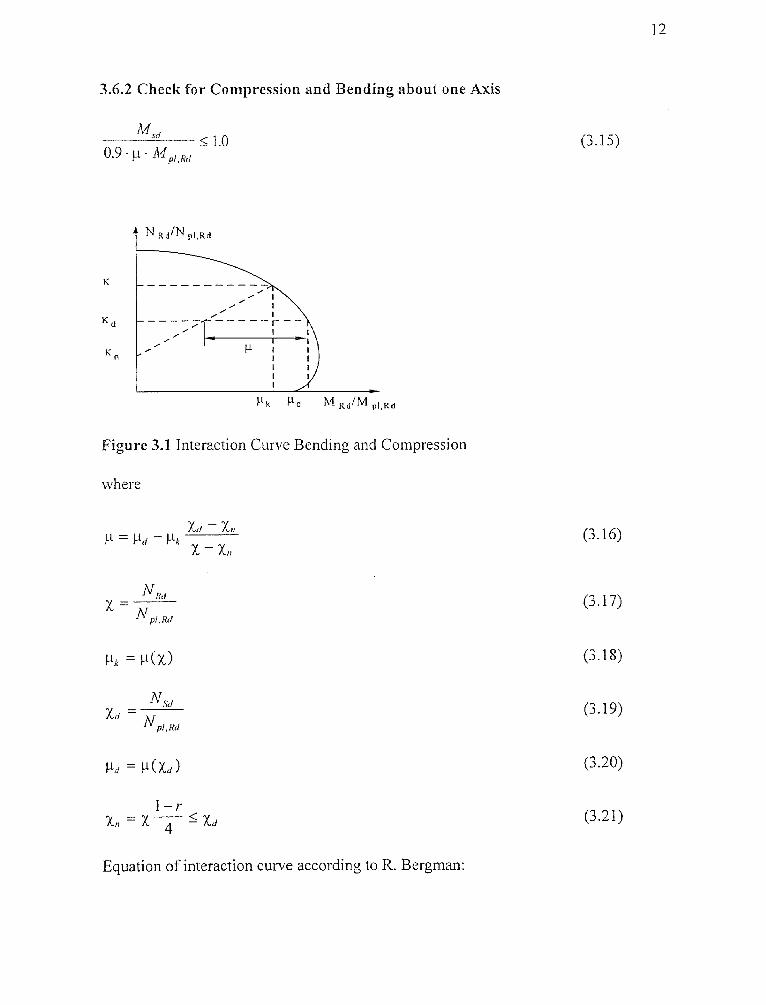
3.6.2 Check for Compression and Bending about one Axis
1 2
Figure 3.1 Interaction Curve Bending and Compression
where
(3.17)
(3.18)
(3.19)
(3.20)
(3.21)
Equation of interaction curve according to R. Bergman:

13
(3.22)
(3.23)
(3.24)
(3.25)
(3.26)
(3.27)
(3.28)
For concrete encased I-Beams with bending about the y-axis and 6 > 0.6, it could
happen that for x > χc . the above equation yields too small μ-values. The following
equation should be checked to see if it yields greater values and therefore controls:
3.6.3 Check for Compression and Biaxial Bending

The influence of imperfection is usually only to be considered for the axis that is most
endangered for failure, i.e. for the check of the axis that is less endangered Ltd can be
used instead of .
3.7 Check of Load Transfer and Ultimate Shear Strength
Load Transfer:
• The load transfer has to formed so that the slip in the bonding due to force
transmission does not violate the assumptions for the design.
• The length of the transmission should not be greater than two times the
corresponding width of the column.
• For I-Beams with concrete filled flanges stirrups must be used to provide a transfer
between steel shape and concrete (Stirrups welded or continuing through the web).
Ultimate Shear Strength:
• Shear stresses have eventually to be considered. The stresses can be computed
according to elastic calculations.

Allowable Shear Stresses:
If the shear stresses exceed the figures in Table 3.3, studs must be used.
Table 3.3 Allowable Shear Stresses N/mm ²
15
3.8 Ultimate Axial Strength
N pl ,Rd = Act • f yd Ac • a f cd -1- s • f sd (3.33)
where
area of steel shape, concrete, and reinforcement
fyd-r A la
Lk f cd γc
f sk
fsd=
fy fck and fsk characteristic strength in accordance with EC3 and EC2
partial safety factor for steel
partial safety factor for concrete
partial safety factor for reinforcement

16
= 1.0 for concrete filled tubes
a, = 0.85 for other cross sections
For concrete filed pipes the positive effect of tying can be considered, if:
•
d• M NSd10
The plastic ultimate normal force is then
where
3.9 Plastic Ultimate Normal Force of the Concrete
N pm,Rd = Ac f cd (3.40)
3.10 Ultimate Moment
(3.41)
(3.42)
(3.43)
where
Wpa, W and W plastic section modulus of steel shape, reinforcement, andps pc
uncracked concrete.
Wpan, Wpsn und Wpcn plastic section modulus of steel shape, reinforcement, and
uncracked concrete in the area 2 h„.
The equations to determine the location of the neutral axis h„ and the plastic section
modulus are given in Appendix A.
17

CHAPTER 4
COMPARISON OF THE AMERICAN AND EUROPEAN METHODS
4.1.Nominal Flexural Strength M,1
AISC gives a very simplified equation to determine the nominal flexural strength
according to Galambos and Chapuis (1980), whereas the Eurocode 4 provides a more
exact approach. For the determination of the nominal flexural strength according to
Eurocode 4 the actual neutral axis is computed and gives the base to compute the
nominal flexural strength. In the following example the nominal flexural strength for a
typical cross-section is computed according to both methods. Only bending about the
strong axis is regarded. The influence of the reinforcement is neglected.
Figure 4.1 Concrete Encased I-Section
Section Properties
As = 96.4 in ²
A„ = 36.4 in2
18

4.1.1. Nominal Flexural Strength M„ according to AISC
19
4.1.2. Nominal Flexural Strength M„ according to Eurocode 4

20
The results show that the ultimate moment is the same for both methods. The ultimate
moment resistance occurs when the concrete is cracked to half height, i.e. the tension
stresses due to bending are overpressed by compression due to the axial force so that
the neutral axis is in the middle of the cross-section.

21
4.2. Interaction
AISC takes combined flexure and bending into account by a linear interaction between
axial strength and flexural strength. Thus, the positive effect of the axial force on the
resisting moment is not taken into account like it is in Eurocode 4. This results in over-
designed columns and waste of material. The more economical approach is to
determine the moment capacity corresponding to the actual axial force (Figure 3.1).
4.3. Tying Effect in Circular Tubes
In the case of concrete-filled circular tubes the compressive strength of the concrete is
enhanced by the containment through the circular tube. Eurocode 4 takes this into
account by increasing the ultimate axial strength. The hoop stresses in the steel tube
cause a reduction of the yield strength of the steel, but are not accounted for in
Eurocode 4.

APPENDIX A
PLASTIC SECTION MODULUS OF TYPICAL CROSS-SECTIONS
Cross-Section A.1
z
Figure A.1 One I-Section Rectangular Encased
Bending about y-axis:
(a) Neutral axis in the web of the steel shape: hny, h I 2 -
'79

(b) Neutral axis in the flange of the steel shape: h / 2 - 5_ h„„. h / 2
'7 3
(A.5)
(A.6)
(A.7)
(A.8)
(A.9)
(A.10)
(A.11)
(A.12)
(c) Neutral axis outside of the steel shape: h / 2 h„,5_ h, / 2
Bending about z-axis:
(a) Neutral axis in the web of the steel shape: h,, 5_ tw / 2

(b) Neutral axis in the flange of the steel shape: r. 12 hnz <= b I 2
24
(c) Neutral axis outside of the steel shape: h,,,> b / 2

Cross-Section A.2
25
Figure A.2 Two I-Sections Rectangular Encased
Bending about the y-axis:
(a) Neutral axis in the web of the steel shape 2: h„, 5. t„, / 2
W ypan = (h, + tw1) • h, 2„
(A.17)
(A.18)
(A.19)
(A.20)

(b) Neutral axis in the flange of the steel shape 2: t w, / 2 < hny, < h, / 2
26
(c) Neutral axis in the web of the steel shape 1: b, / 2 h, / 2 -
(A.23)
(A24)
(d) Neutral axis in the flange of the steel shape 1: h 1 / 2 -
(e) Neutral axis outside of the steel shape 1: h, hny
(A.25)
(A.26)
(A.27)
(A.28)

Bending about z-axis
27
(b) Neutral axis in the flange of steel shape 1: t w1 / 2 5_ / 2
(A33)
(c) Neutral axis in the web of steel shape 2: b1 / 2 hnz <= h2 / 2 - tf2
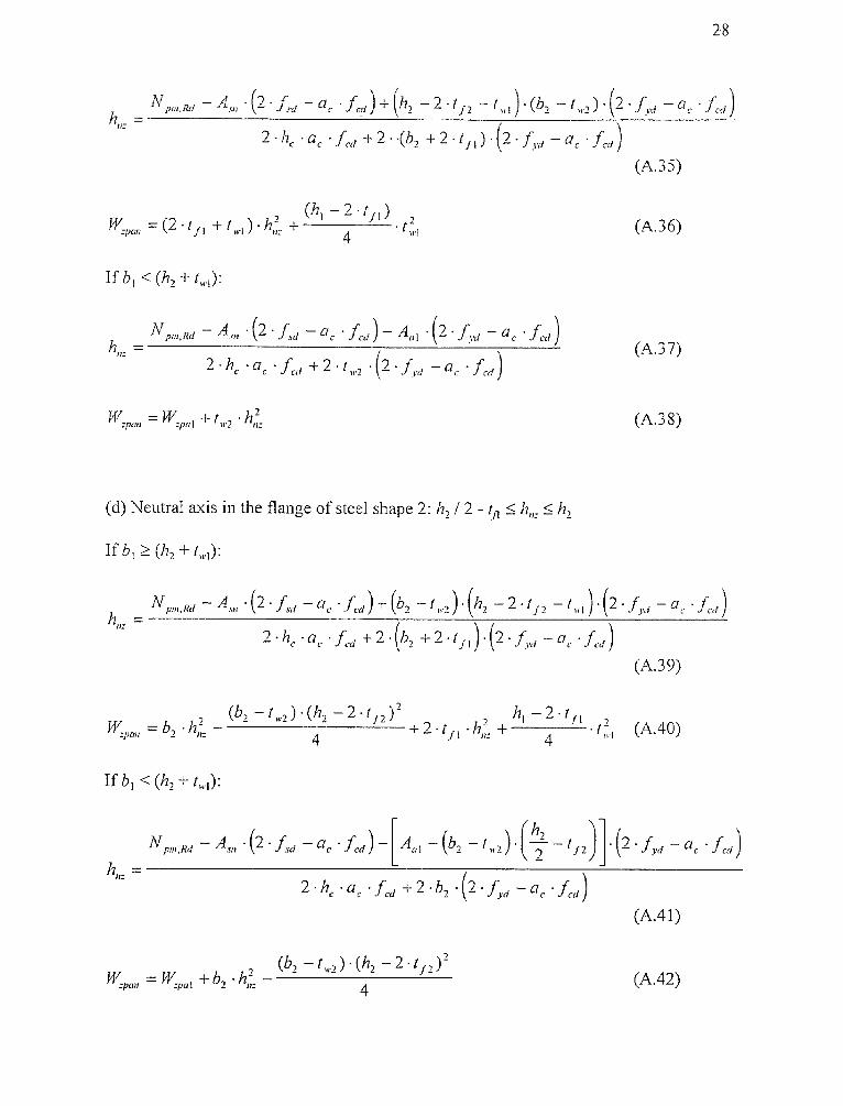
(A.35)
(A.36)
(A.37)
28
(d) Neutral axis in the flange of steel shape 2: h, / 2 - t fl h„. h,

(e) Neutral axis outside of steel shape 1 and 2: h, I 2 < hnz> b, 12
29
(A.43)
(A.44)

Cross-Section A3
30
Figure A.3 Solid Section Rectangular Encased
Bending about the y-axis:
(a) Neutral axis inside of steel shape: h / 2
(b) Neutral axis outside of steel shape: hny > h 2

11
sou
Bending about z-axis:
(a) Neutral axis inside of steel shape: 17,,, b / 2
(b) Neutral axis outside of steel shape: h,,,> b 2
31
(A.49)
(A.50)
(A.51)
(A.52)
(A.53)
(A.54)
(A.55)
(A.56)

h
Figure A.4 One I-Section Circular Encased
Bending about y-axis:
(a) Neutral axis in the web of the steel shape: h„), h I 2 -
Cross-Section A.4
32
(A.57)
(A.58)
(A.59)
(A.60)
(b) Neutral axis in the flange of the steel shape: h / 2 - h„,, h / 2

(c) Neutral axis outside of the steel shape: h I 2 5_ h 1 I 2
33

(b) Neutral axis in the flange of the steel shape: t w / 2 < h„_< b / 2
34
(A.69)
(c) Neutral axis outside of the steel shape: h,> b / 2

Cross-Section A.5
35
Figure A.5 Two I-Sections Circular Encased
Bending about the y-axis:
(a) Neutral axis in the web of the steel shape 2: h , 1„, / 2
(b) Neutral axis in the flange of the steel shape 2

(A.77)
(A.78)
(c) Neutral axis in the Feb of the steel shape 1: b, 1 2 :5_ h„, S h,12 -
(A.79)
(A.80)
(d) Neutral axis in the flange of the steel shape 1: 1'2 1 / 2 - tfl <= 5 h„),15_ hl
(A.81)
(A.82)
(e) Neutral axis outside of the steel shape 1: h 2 < h„,
(A.83)
(A.84)
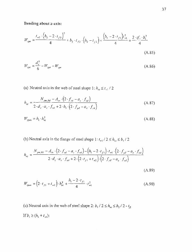
Bending about z-axis:
37
(A.85)
(A.86)
(A.87)
(A.88)
(a) Neutral axis in the web of steel shape 1: h, tw1, / 2
(b) Neutral axis in the flange of steel shape 1: t„, / 2 b, / 2
(c) Neutral axis in the web of steel shape 2: b 1 / 2 h„ h, / 2 -
If b +

(d) Neutral axis in the flange of steel shape
38
(A.97)

(e) Neutral axis outside of steel shape 1 and 2: h, I 2 bl I
(A.99)
(A.100)

Cross-Section A.6
40
Figure A.6 Solid Section Circular Encased
Bending about the y-axis:
(a) Neutral axis in the steel shape: dl 2
(A.101)
(A.102)
(A.103)
(A.104)
(b) Neutral axis outside of the steel shape: h,„,> dl 2

Bending about the z-axis:
(a) Neutral axis inside of the steel shape: h,„< dl 2
(b) Neutral axis outside of the steel shape: h„,> d / 2
(A.105)
(A.106)
(A.107)
(A.108)
(A.109)
(A.1 10)
(A.111)
(A.112)
41

t „ • (h — 2 .1 f )
(a) Neutral axis in the web of the steel shape:
+ b • t f • (A.113)
(A.114)
(A.1I5)
(AA 16)
Cross-Section A.7
4
hy
Figure Al One I-Section Partly Encased
Bending about y-axis:
42
(b) Neutral axis in the flange of the steel shape: h / 2 - tf h„,, h I 2

fly
43
(A.117)
(A.118)
Bending about z-axis:
(a) Neutral axis in the web of the steel shape: h i, 2
(A.I2I)
(b) Neutral axis in the flange of the steel shape: t w / 2 b / 2
(A.124)

Cross-Section A.8
44
Figure A.8 Two I-Section Partly Encased
Bending about the y-axis:
(a) Neutral axis in the web of the steel shape 2: t„2 / 2
(A.125)
(A.126)
(A.127)
(A.128)
(b) Neutral axis in the flange of the steel shape 2: tw2 / 2 < hny< b, / 2

AT Npn,Rd Asn (2 fsd —a c • f cd) — w2 • (h2 —2 if 2 ) • (2 110 ac • Ld )
2'b, • a c - + 2 (2t f2 t wl ) • (2 • — a, fed)
(A.129)
(A.130)
(c) Neutral axis in the web of the steel shape
(A.131)
(A.132)
(d) Neutral axis in the flange of the steel shape 1: h l / 2 - t fl S 17n),
(A.133)
(A.134)
Bending about z-axis:
45
(A.135)

(A.136)
(A.137)
(A.138)
46
(b) Neutral axis in the flange of the steel shape 1: t„,/ 2 / 2
(A.139)
(A.140)
(c) Neutral axis in the web of the steel shape 2: 13 1 / 2 / 2 -
A.I4I)
',A.142)
(d) Neutral axis in the flange of the steel shape 2: h 2 / 2 - hn,

47

Cross-Section A.9
48
Figure A.9 Two I-Sections Partly Encased
(A.145)
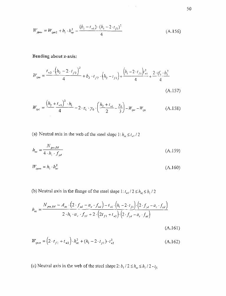
(A.146)
Bending about the y-axis:
(A.147)
(A.148)
(a) Neutral axis in the web of the steel shape 2: kJ, t,,,2 I 2

(b) Neutral axis in the flange of the steel shape 2: I 2 S hny S b, I
(A.I51)
(c) Neutral axis in the web of the steel shape 1: b, / 2 h, I 2 -
Iterative Solution:
(d) Neutral axis in the flange of the steel shape 1: h l / 2 - hny
50
(A.157)
(A.158)
(A.159)
(A.160)
(a) Neutral axis in the web of the steel shape 1: t„,, / 2
(b) Neutral axis in the flange of the steel shape I: to / 2 5 b 1 I 2
(A.161)
(A.162)
(c) Neutral axis in the web of the steel shape 2: 1) 1 / 2 5 I/ 1 / 2 -
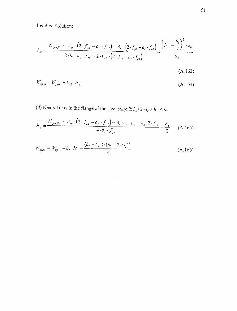
Iterative Solution:
51
zo
(d) Neutral axis in the flange of the steel shape 2: h, / 2 - tf2 h„ h,

Cross-Section A.10
52
vz
Figure A.10 Filled Circular Tube

Cross-Section A.11
5.3
*z
Figure A.11 Circular Encased Cross-Section in Tube
Bending about the y-axis:
(a) Neutral axis inside of the steel shape: di / 2
(A.171)
(A.172)
(A.173)
(A.174)
(b) Neutral axis outside of the steel shape: hny> di , / 2

Bending about the z-axis:
(a) Neutral axis inside of the steel shape: h„, d, / 2
(b) Neutral axis outside of the steel shape: h,,,> d. / 2
(A.175)
(A.176)
(A.177)
(A.178)
(A.179)
(A.180)
(A.181)
(A.182)
54

Cross-Section A.12
55
Figure A.12 One I-Section in Filled Tube
Bending about the y-axis:
(a) Neutral axis in the web of the steel shape: hn, LC. h / 2 -
= (t i. + 2• t) •
(A.183)
(A.184)
(A.185)
(A.186)

at + 2 h 2Jr (A.190)
(b) Neutral axis in the flange of the steel shape: h / 2 - if h„,,h 12
56
(A.188)
(c) Neutral axis outside of the steel shape: h / 2 dl 2
(A.189)
Bending about the z-axis:
(a) Neutral axis in the web of the steel shape: hn, t„. / 2

(b) Neutral axis in the flange of the steel shape: t w / 2 <= h,,< b / 2
57

Cross-Section A.13
Figure A.13 Filled Rectangular Tube
58
(A.199)
(A.200)
(A.201)
(A.202)

Bending about the z-axis:
59
(A.203)
(A.204)
(A.205)
(A.206)

REFE RENCES
1. American Institute of Steel Construction, Manual of Steel Construction - Load andResistance Factor Design, AISC, Chicago, Illinois, 1984
2. R. Bergman, Vereinfachte Berechnung der Querschnitrsinteraktionskurven fursymmetrische Verbundquerschnitte, Festschrift Roik, Techn. -Wiss. Mitteilungen,Institut fir Konstruktiven Ingenieurbau, Ruhr-Universität Bochum, Germany,1984
3. DIN, Eurocode 4 Teil 1-1 - DIN V ENV 1994-1-1, Beuth Verlag Berlin, Germany,1994
4. T. V. Galambos, J. Chapuis, LRFD Criteria for Composite Columns and BeamColumns, Revised Draft, Washington Univ., Dept. of Civil Engineering, St. Lois,Missouri, 1980
5. P. Johnson, Composite Structures of Steel and Concrete, John Wiley & Sons, NewYork, 1975
6. R. Narayanan, Steel - Concrete Composite Structures, Elsevier Applied Science,London, 1988
7. Charles W. Roeder, Composite and Mixed Construction, ASCE, New York, 1984
60