cprc - cradpdf.drdc-rddc.gc.ca · introduction this report is a summary of application studies of...
TRANSCRIPT
CPRC CANADIAN POLICE RESEARCH CENTRE
CCRP CENTRE CANADIEN DE RECHERCHES POLICIÈRES
TM-05-98 EDGE OF LIGHT - OPERATIONAL ASSESSMENT By: Mr. M. Brosseau,
Central Bureau for Counterfeits, Central Forensic Laboratory Royal Canadian Mounted Police and MS. C. Gilmour, Laboratory and Scientific Services Dir., Revenue Canada
TECHNICAL MEMORANDUM Submitted by Canadian Police Research Centre December, 1999
NOTE: Further information about this report can be obtained by calling the CPRC information number (613) 998-6343
NOTA: Pour de plus ample
renseignements veuillez communiquer avec le CCRP au (613) 998-6343
© HER MAJESTY THE QUEEN IN RIGHT OF CANADA (2000) © SA MAJESTÉ LA REINE DU CHEF DU CANADA (2000)
as represented by the Solicitor General of Canada. représentée par le Solliciteur général du Canada.
EXECUTIVE SUMMARY
The “edge of light” (EOL) technology was developed at the National ResearchCouncil - Institute of Aerospace Research (NRC-IAR). The technology wasinitially evaluated in the NRC laboratory (see technical memorandumTM-21 -95). As a result of this evaluation and the potential of “EOL” technologyin the law enforcement community it was decided to have the RCMP CentralForensic Laboratory and the Revenue Canada Laboratory and ScientificServices Directorate to operationally evaluate the technology. This technicalmemorandum describes these two evaluations.
Appended to this technical memorandum is the NRC-IAR Fact Sheet and TechSheet entitled, “The Edge of Light Enhanced Optical NDI (Non-DestructiveInvestigation) Technique”.
SOMMAIRE
La technologie « edge of light (EOL) a été mise au point au Conseil nationalde recherches - lnstitut de recherche aerospatiale (CNR-IRA). La technologiea d’abord été évaluée dans les laboratoires du CNR (voir le documenttechnique TM-21 -95). Par suite de cette evaluation et compte tenu du potentielde la technologie EOL pour les services de police, il a été convenu que leLaboratoire judiciaire central de la GRC et le Service des travaux scientifiqueset de laboratoire de Revenu Canada évalueraient la technologie sur le planoperationnel. Le present document technique décrit ces deux evaluations.
Le document technique est accompagne de la fiche signaletique du CNR-IRAet de la fiche technique intitulée The Edge of Enhanced Optical NDI(Non-Destructive Investigation Technique
“EDGE OF LIGHT - OPERATIONAL ASSESSMENT” - RCMP
INTRODUCTION
This report is a summary of application studies of the Edge of Light (EOL)technology to operational cases analysed at the Central Bureau for Counterfeits(CB4C) of the RCMP, Central Forensic Laboratory in Ottawa. The first prototypeof EOL was introduced to CB4C in May 1996, it was tested for a period of sixmonths. A second generation of EOL was presented to CB4C in May 1997 fortesting for a period of also six months.
In a Technical Memorandum from the CPRC dated June 1995, different forensicapplications were tested, ranging from tests on counterfeit money to handwritingindentations, altered credit cards and fingerprints - areas commonly examined bythe RCMP document section. EOL technology appears to be a promisinginstrument.
POTENTIAL APPLICATIONS FOR EOL IN THE RCMP DOCUMENT SECTION
The main possibilities of the EOL technology are primarily in the capacity of theEOL to decipher and illustrate some types of alterations in specific cases. Forexample, in cases of bleached banknotes, the EOL technology could provide a“map topography” of the lntaglio printing of a genuine bleached banknote (i.e. anote that has been bleached and fraudulently reprinted to a higher denomination).Furthermore, the EOL could decipher cases of mechanical erasures of typewrittenor handwritten information on travel documents such as passports. The EOL couldalso provide additional information (i.e. its “map surface reading” capabilities) thatwere not available through other apparatus such as the Video Spectral Comparator(VSC) or the ESDA.
EOL GENERATION I
Several tests of banknotes, travel documents and handwriting indentations wereconducted with the EOL I. We quickly came to the conclusion that EOL I was morea demonstration of the EOL principle rather than a true forensic instrument. Theresults of the EOL I were limited by two main factors:
1) EOL I being a hand held scanning device rolling on a surface, images fromEOL could be distorted by a deficient scanning movement. The thickness of adocument created some problems in unequal surface. For example,biographical data are located on the first pages of a passport resulting into anunequal reading surface for the scanner (i.e. a few pages on one side of thebooklet and several pages on the other side create a difficult scanningmovement).
2) It was not possible in EOL I to adjust the slit reading angle of the scanner, inorder to vary the band width of type edge zone of reading of EOL. Variationsof the slit angle has proven to be a very significant factor of image optimizationor reduction in its quality. For example, an adjustment obtained for theexamination of printed matter would provide poor result in a handwriting case.
EOL GENERATION II
The presence of an inverted scanner on a flat surface was a major improvement ofEOL II. The scanning movement was now mechanically performed and presentedmore consistency in the image quality (less distortion). The EOL II enabled also thepossibility of adjusting the slit angle of the scanner and to obtain a control value ofthe height of the scanning head components. Slit angulation and height areimportant components for producing a quality image.
Forensic applications tested with EOL II
Several tests have been conducted from May 1997 to September 1997 of EOL II.We have concentrated our efforts in determining reliable setting for producing agood quality image for two categories of examination: printed material andhandwritten alteration.
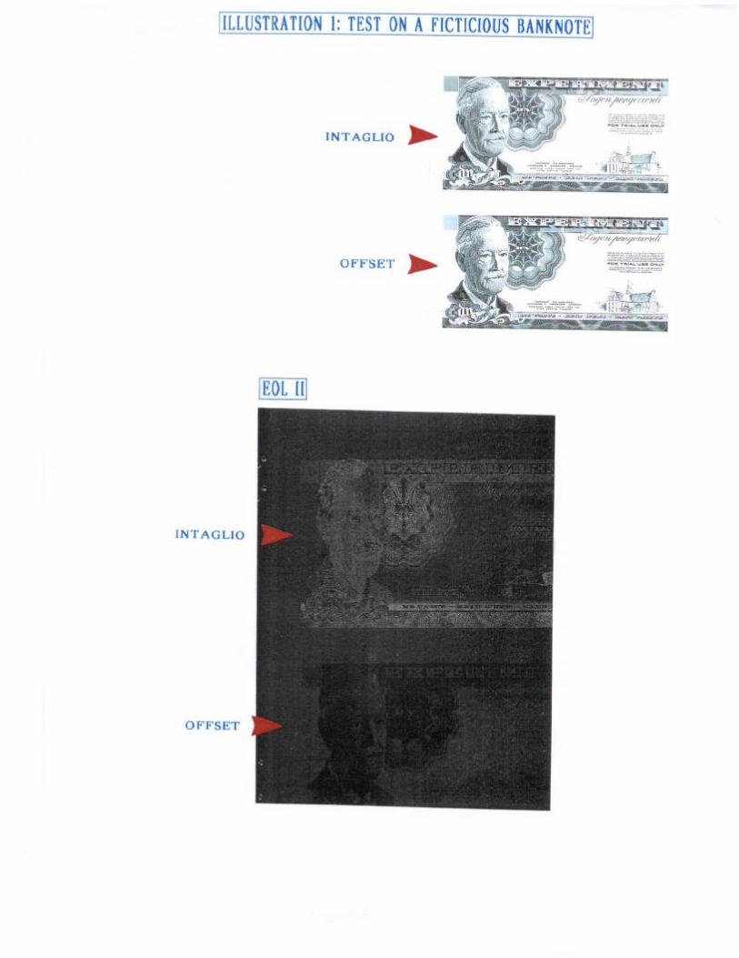
In illustration 1, differences of a fictitious banknotes printed in intaglio on top andoffset at the bottom were successfully recorded by EOL at a specific setting. It wasrevealed that EOL II could generate a wide span of image quality but differencesbetween offset and intaglio printing could be lost by an improper setting. EOL IImust ALWAYS be used with calibration standards before conducting a formalexamination. This process is necessary to determine the significance of differencesor similarities (i.e. resulting of a difference in the comparison of two documents andnot a result of a misadjustment of the EOL). Settings are very critical in EOL andshould be recordable in order to provide full control and to give the possibility toredoing an examination under the same conditions.
Printing standard, erased writing standards, indented standards and embossedstandards were developed to test the EOL II. Several experimentations in thedetermination of slit/height measurements were also necessary to obtain positiveresults. While some “key settings” appeared to be better for printed matters, othersettings for indented writing material or different settings for mechanical erasedinformation, it was not possible to categorize a specific setting to a specific type ofalteration of examinations. A good quality image was obtained for mechanicalerasure at a setting of 70/1 4/1 38, height 1.9075 while for a printed matter the bestsetting was 70/50/140, height 1.9480. But in other cases the same settings wouldprovide poor results. It appears that the EOL will give its full potential when a
“daisy wheel of settings” is systematically done for each case in order to determinethe best image quality. The use of an EOL standard is also a prerequisite to anyexamination with the EOL, in order to determine the significance of the result(images produced are not the result of an improper adjustment).
Different types of comparison conducted with EOL II
A) Printing matters: presence/absence comparison and comparison ofdifferent printing processes
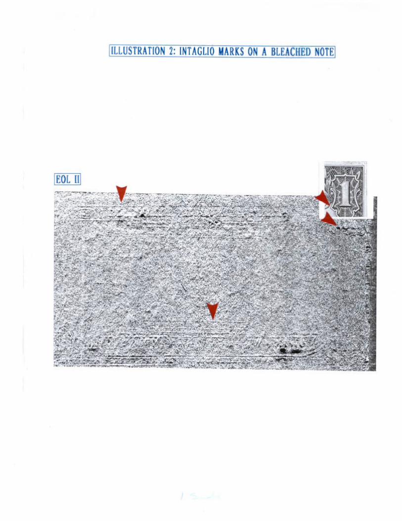
In most cases presented to the public, the EOL technology was used todemonstrate the presence/absence of a specific element or reveal the presenceof different printing processes. We have conducted several tests to determinethe presence of residual intaglio printing (Intaglio produces a raised image) inOffset counterfeit notes (Offset creates a flat image). In illustration 2, somelntaglio marks were deciphered in what we assume to be a bleached genuine$1 United States Federal Reserve (USFR) banknote. This note was bleachedand fraudulently reprinted into a $100 counterfeit USFR Note. The EOL II hasclearly demonstrated important possibilities in this area.
B) Quality evaluation in the case of two documents produced with the sameprinting process
The presence/absence of printing processes has been demonstrated with theEOL II but subsequent testing had to be made in the evaluation of counterfeitsbearing the same printing process that is in the genuine. Some high qualitycounterfeits (acid etch counterfeits) were compared with intaglio genuine notesusing EOL II. The analysis revealed that EOL II had a limited success at thisstage of development in revealing significant differences. This limited successwas caused by limitations in the enlargement capacities of the scanned imageand the inability of EOL II to compare minute surface details. The EOL II couldnot provide a macroscopic image magnification quality. To match a forensiclevel quality similar to those commonly produced by our instruments (such aswith the Video Spectral Comparator or with a photo microscope) the EOLtechnology must improve its ability of scanning small zones of evaluation, aboutthe size of ONE typewritten character.
C) Altered documents
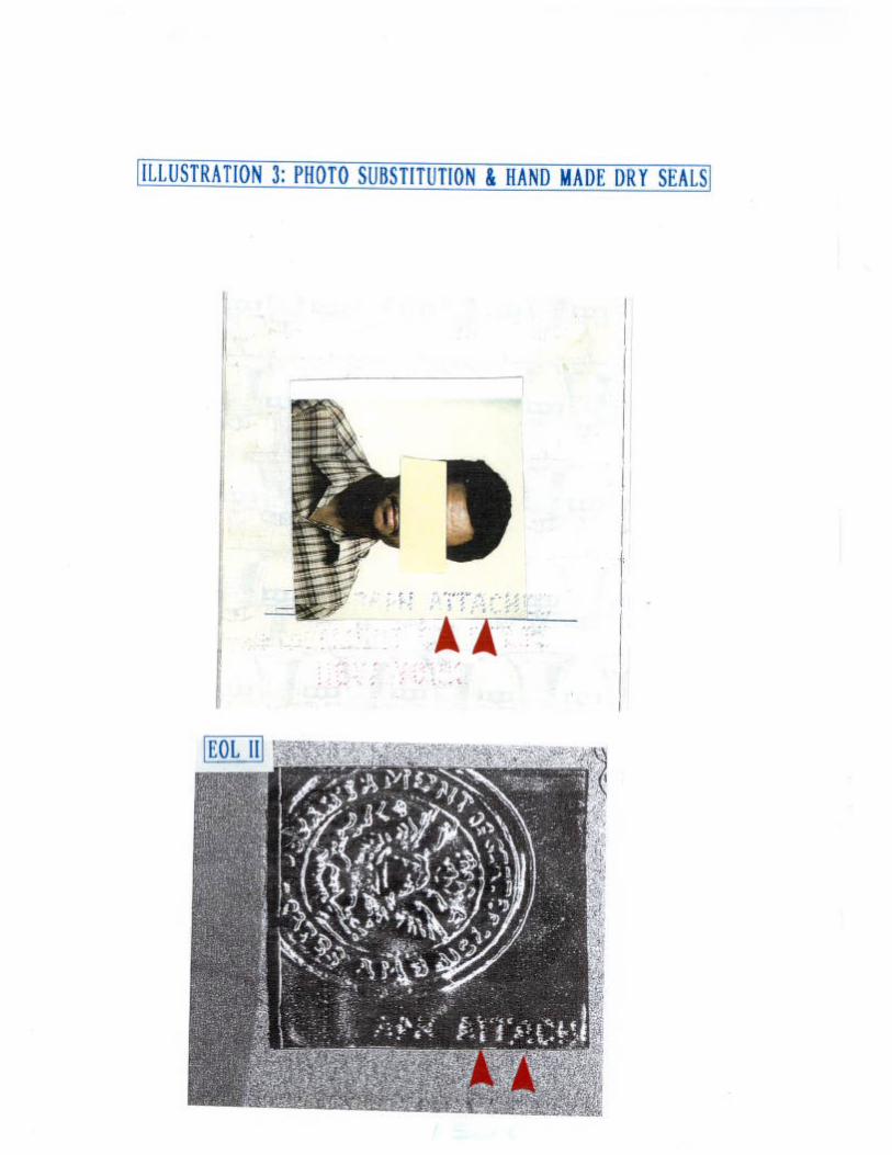
Several tests were also conducted in the area of alteration of travel documents,mainly in cases of mechanical erasures and handwriting indentations.Illustration 3 provides a case of a dry seal (hand made) done in a photosubstitution in a United States passport. Despite the fact that the enlargementsobtained from EOL were sufficient to reveal problems, greater magnification is

required to reveal significant differences when comparison with a genuinemechanical dry seal (both letters “A” and "T" of attached could be compared buta higher magnification is essential to conduct a forensic comparison).
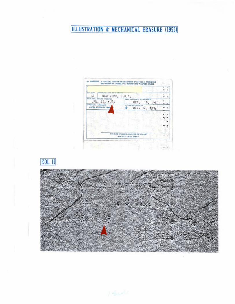
In illustration 4 taken from the same passport, the digit "5" of 1953 wasprobably “1963” (mechanical erasure of a digit "6"). Again the EOL II hasprovided limited capabilities in enlarging the erased area in order to illustratefibre disturbance. We believe that the actual limitation of EOL is not the resultof the technology itself but more the consequence of the use of scanningcomponents designed for office use applications and not fully adapted to EOLII (insufficient scanner quality and limited software).
FUTURE APPLICATIONS OF THE EDGE OF LIGHT TECHNOLOGY INFORENSICS
We have not evaluated the Edge of light technology by calculating the number ofpositive results that this instrument has provided us through six months ofevaluation. We have asked ourselves if the EOL technology could provideinformation that is not available through the VSC or the ESDA.
1. In our opinion, the EOL provides a new technique of evaluations in forensics.At this stage of development, we think that the EOL would provide limitedcomplementary results to information extracted from a VSC or an ESDA.
2 . The EOL technology would provide unique results that cannot be obtained witha VSC or an ESDA if further developments were made to better adapt EOLtechnology to forensic applications.
SUGGESTED DEVELOPMENTS
1. Better scanning resolution
The actual resolution of EOL II is inferior in quality renditions to other apparatussuch as VSC or photo-microscope. Enlargement setting should be targeted toobtain a full scanning zone of the size of ONE typewritten character.
2. Automatic compensation for slit angle and height adjustment (without areadjustment)
A compensation mechanism should be included to obtain the same slit angleat a different height. In EOL II, a new setting had to be done with the “standardsettings” each time the height was changed.
3. “Daisy wheel scanning” conducting automatically a series of imagescapture
It was not possible with the EOL to determine the perfect setting for a particulartype of examination or alteration. A mechanical erasure could be decipheredat a certain angle and height in one case and be different in anothermechanical erasure case. The pre-adjustment of 6 or 8 settings performedautomatically would greatly improve the capacity of EOL. The examiner couldperform other duties while the images are produced. A more extensiveexamination with the best specific setting could be done by the examiner.
4. VSC capabilities combined to EOL
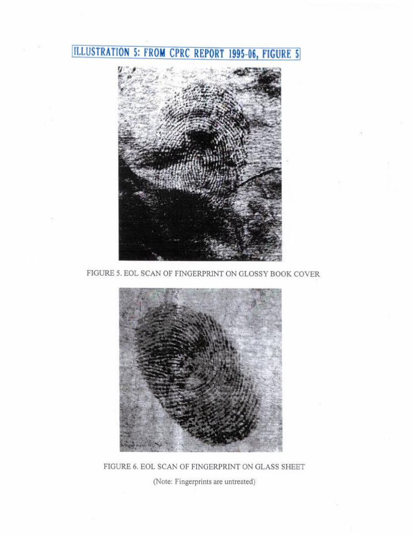
In the CPRC Technical Memorandum in Figure 5 an EOL scan of a fingerprintwas recorded. A fluorescence effect may have been recorded in such cases.Such effects are similar to those produced by the VSC and extensively used inforensic examination.
Instead of the usual light source enclosed in the apparatus, a combination ofthe EOL with a fibre optic cable adapted to a Luma-light source could bring newpossibilities. Further to this controlled light source, the possibility of a rotatingwheel of different spectrum of red filters would increase the EOL to a “VSCstatus”. The VSC is the best used instrument in forensic examination ofdocuments. The VSC is a closed TV circuit system emitting a blue-green lightsource of 480-580 NM and capturing an image under different red filters,varying from 600 to 850 NM. The VSC does not provide the capabilities of a“map surface reading”.
5. Values recorded on the screen
Forensic examination requires the registering of all parameters in order to havethe capacity of redoing a case under the same conditions. For the EOL, suchrecording is critical since the image quality is dependent on slit angle andheight measurement. All these values should be recordable at the same timeimages are saved. This would insure that all significant adjustments would bepresent to redo an examination.
CONCLUSION
EOL is a promising instrument that offers a new forensic examination technique.Results produced with the EOL are not obtainable with the ESDA machine or withthe Video Spectral Comparator (VSC). At this actual stage of development, theEOL is not yet capable of producing significant complementary information inforensic examination. But the EOL technology offers interesting forensicpossibilities and further developments should be considered. The main area ofdevelopment of the EOL technology for forensics should be in the area of obtaininga better scanning resolution, performing automatic capturing, combining VSCilluminations with EOL and using a measurement log recording systemautomatically saving the values with the image capturing. This would put the EOLtechnology at the status of a leading edge forensic apparatus.

List of Illustrations - RCMP report
Illustration 1 - Test on fictitious banknote (EOL II)
Illustration 2 - lntaglio marks on a bleached note (EOL II)
Illustration 3 - Photo substitution and hand made dry seals (EOL II)
Illustration 4 - Mechanical erasure (1953) (EOL II)
Illustration 5 - From CPRC report 1995-96, Figure 5 and 6
" EDGE OF LIGHT - OPERATIONAL ASSESSMENT” - REVENUE CANADA
INTRODUCTION
Document examiners routinely examine documents for indented or embossedmaterial. Oblique lighting and a microscope is one method used for these types ofexaminations. The ESDA (Electra-Static Detection Apparatus) is another methodusually employed in the examination of indentations.
The following report provides an evaluation of the Edge of Light technologywith respect to decipherment of indentations and examination of embossmentdefects on questioned documents and other types of potential exhibit material. TheEOL apparatus was developed by the Institute for Aerospace Research, Structures,and Materials Laboratory, National Research Council Canada. The flat-bedscanner phase II prototype version was set-up at our laboratory. An illustration’of the apparatus set-up is seen in Figure A.
PROCEDURE
During the time period of evaluation, many different types of exhibits anddocuments were examined. See Table 1 for a list of the types of materialsexamined.
In each case the following basic steps were taken:
1. Initial settings were noted. A) the height of the scan head above the exhibit(zeroed first, then adjusted from the zero setting at the top of the micrometerattached to the scanner), B) the values for F1=Optical Slit Adjustment(notchanged), F2=EOL edge(mirror adjustment with range of 0 to 100 units),F3=Focus (with a range of 0 to 150 units). C) orientation of the exhibit to thescan head (generally parallel to the scan head, with the scan coming from theleft to right across the document/exhibit). D) Vacuum on or off, with or withoutplastic covering over exhibit.
2 . All scans were done at 600dpi resolution. This was set in HP Scanjet II underCustom print path.
1 TM 2 l-95/7 Micro Inspection Technology - EOL - Edge of Light Optical Enhancement Technology,Technical Memorandum April 1997, by A. Marincak, R. W. Gould, J . P. Komorowski, Insti tute forAerospace Research, Structures, Materials, and Propulsion Laboratory, National Research CouncilCanada.
2 Ibid, Addendum
3 . Images obtained were usually unenhanced but, when required, the contrastand/or brightness was adjusted through Picture Publisher (the softwarepackage on the computer).
4 . Images were saved as TIFF files so that no loss of detail occurred (as is thecase in some image formats such as JPEG).
RESULTS
Due to the amount of raw data generated in the evaluation of the materials listedin Table 1, only a sampling of results are illustrated here. The EOL parameters foreach of the illustrations are described within the Figures where they appear.
Indentations
Four types of indentation cases/tests are reported. The first case is a prepared testsample of indented handwriting, the second, an actual exhibit where questionedindentations and erased writings were examined, the third, an examination ofindentations that were covered with scotch tape on a shredded document, and thefourth, fuser roller impressions in the surface of toner on a laser printed test page.
Case #1 : Figure 1 illustrates the prepared test sample of handwritten entries andthe page that was directly below it when it was written. The upperimage (page 1) shows what was originally written with variouspressures (ie. a = heavy pressure, b = light pressure, c = moderatepressure), while the lower image (page 2) is the page that was presentbelow the page with the original writing on it. Results from the EOL ofthe indented impressions on page 2 are seen in Figure 2. Figure 2 a.illustrates both areas of light and moderate writing pressures. Figure2 b. illustrates just the light writing pressure. The heavy pressure wasfully resolved by the EOL and was not illustrated here. The greatestamount of handwriting stroke detail between b and c was seen in themoderate pressure indentations (area c) of page 2. The weakerindented impressions of (area b) were not resolved well. Figure 3illustrates an ESDA of page 2. Conditions for the ESDA are listed inFigure 3. The ESDA resolved all indentations very well.
Case #2: Figure 4 illustrates questioned exhibit Q5(3), a sheet of lined graphpaper which contained handwriting entries. Please note that anynames were obliterated on this copy of Q5(3). Two questioned areaswere examined on this exhibit. The first was located at the mid-rightside of the page near the word “Writing” in " Replys inWriting”, this was where an erasure had occurred. The second was at
the top left side of the page around the beginning of the secondparagraph. This was where indented writing occurred. See Figure 5for the ESDA of exhibit Q5(3). Multiple trials were done to try andresolve the erased written area. None were successful, as can beseen in the lower image of Figure 5. The upper image of Figure 5,illustrates the indented impressions at the top of the exhibit. Theresolution of detail is much better there. Figure 6 a. illustrates theresults of the EOL technique in the questioned erased area, and Figure6 b. illustrates the questioned indented area results. The EOL imageis very faint in Figure 6 b., only the word “Aug” was partially resolved.The EOL image is better of the erased words “obtaining the new Ford
in Figure 6 a.
Case #3: A shredded document was examined for indentations on the paper butcovered by scotch tape. This type of document would not be wellsuited to ESDA for indentation examination since it was very rippled onthe surface and humidity would not help due to the interference fromthe tape. Figure 7 is a copy of the questioned bottom portion of exhibitD62. Figure 8 is a comparison of EOL results of the area bounded bythe “S” of Phones and the “S” of Shanjhai in line 1 of Figure 7 and the“4” of 24 and “P” of line 3 on exhibit D62, that was covered with scotchtape, with and without using the EOL plastic covering. This case wasillustrated to show that the amount of reflection increased with theplastic covering plus the tape to an extent that it caused interference.The loss of resolution in the images of Figure 8 is due to the reductionin size and detail necessary to be able to print them together in thesame image. The arrows indicate the indented text.
Case #4: A laser printer test sheet was examined for fuser roller impressions inthe toner surface. It was hoped that the EOL would be able to pick upthe pattern in both the solid black and text portions of the test print,thus enabling the EOL to be used as a quick scan technique for fuserroller defects in laser printed documents. Figure 9 illustrates ascanned image and microphotographs of certain sections of the laserprinter test sheet. The test sheet had an area of solid black at the topof the page followed by text. Figure 10 a. illustrates the EOL image ofthe fuser roller impression in the extended dark portion at the top of thepage. The EOL did not discriminate the fuser roller impressions in theprinted text itself, see Figure 10 b.
Embossments
Three case examples of embossed details were examined. The first involved anexamination of printing characteristics on a label that was attached to a cigar boxand on a standard unattached label. The second involved an examination of printridge detail from a treated fingerprint on a magazine page. The third involved theexamination of a questioned embossed area on the collar of a black jacket.
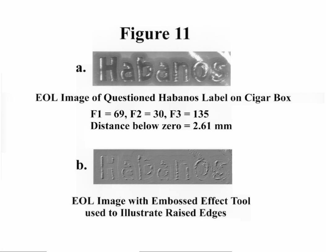
Case #5: Figure 11 illustrates an EOL image (Figure 11 a) and a digitallyenhanced image (Figure Ilb) of a questioned embossed Habanoslabel which was adhered to a wooden cigar box that was 27.4 cm longx 14.1 cm wide x 4.8 cm high. Figure 12 illustrates an EOL image(Figure 12a) and a digitally enhanced image (Figure 12b) of a standardembossed Habanos label which was not adhered to a box. Theamount of damage to the label influences the appearance of theembossed detail. This type of exhibit would not be able to be examinedfor embossment detail with the ESDA due to its odd shape and therequirement for enhancement of the image by the computer.
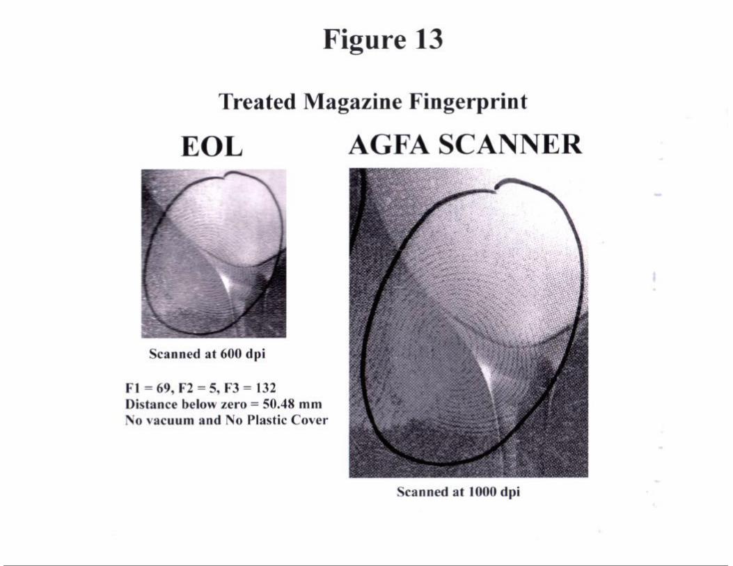
Case #6: Figure 13 is an illustration of a comparison between an EOL image ofa treated fingerprint on a magazine page and a 1000 dpi scannedimage of the same print. The scanned image was done on an AGFAduo-scan scanner set at 1000 dpi resolution. Figure 13 (whichcontains both images) was printed on a HP laser-jet 4V at 400 dpi. Noplastic was used over the magazine page as it had its own reflectanceand due to the possibility that covering it might have removed thetreated embossment. The treated fingerprint ridge detail was nottotally clear on the page, it was hoped that enhancement of the ridgedetail may have been possible. Both images were similar in clarityprior to being printed for their illustration in this report.
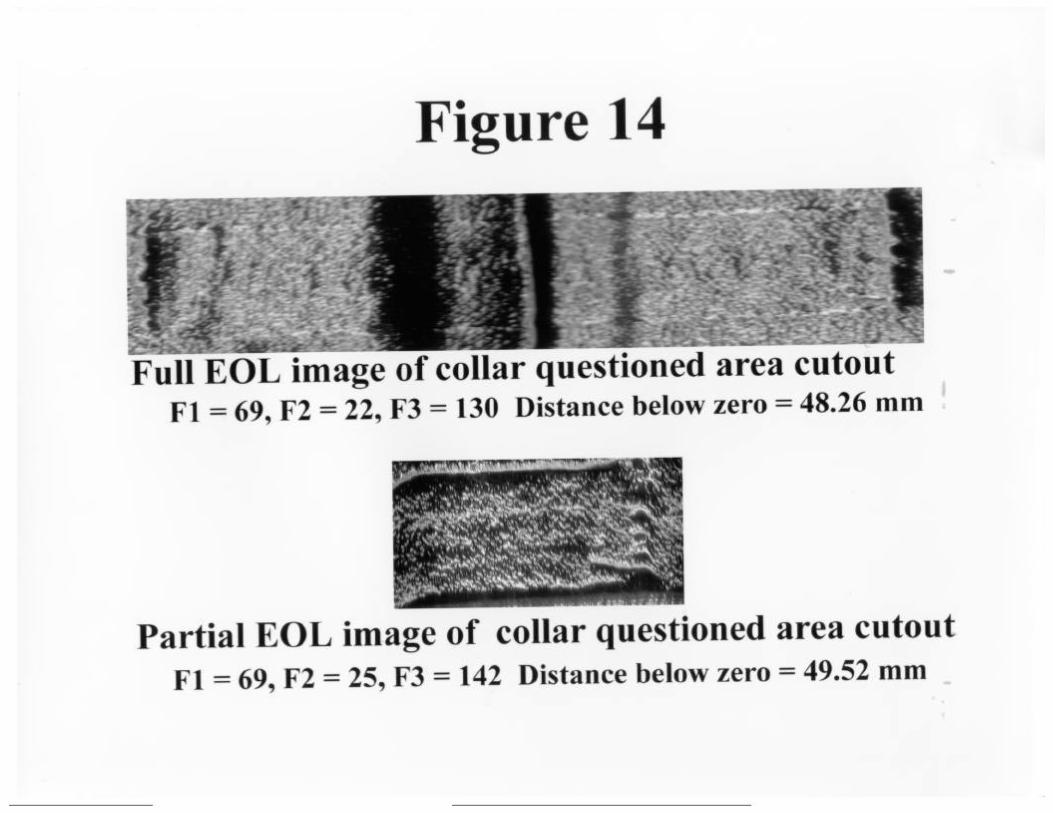
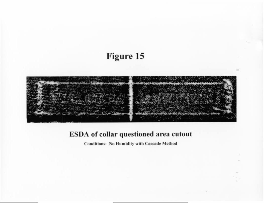
Case #7: Figure 14 illustrates two images taken with the EOL of a questionedembossed area on a cutout of the collar of a jacket. The collar was cutoff of the jacket so that it would lie as flat as possible. Figure 15 is anESDA of the same questioned embossment on the fabric collar cutout.One can see that neither the EOL or the ESDA was able to resolve theimage pattern.
DISCUSSION
In summary, from the preceding illustrations one can see that the EOL worked wellin providing a non-destructive method to examine surface detail information onerased indentations on paper (Figure 6a), moderate pressure indentations on paper(Figure 2a), embossed (raised) images on labels after digital enhancement (Figure11 b), and on odd exhibit materials (ie. wooden box label, paper covered with tape,
glossy magazine page with treated fingerprint - Figures 11 b, 8b and 13respectively). The EOL did not perform well on weak indentations in paper and onfuser roller impressions in toner text (ie. Figures 6b and 10b). Both these types ofindentations require increased resolution. It is also possible that alternateorientation to the scan-head with the averaging of multiple images and/or increasedresolution could have resolved the finer indentation details. Due to time limitations,this could not be explored for this report.
Most of the case materials examined above were actually from casework in thislaboratory and thus the exhibits had to be returned to the investigators. The timeavailable was limited to examining various possible combinations of reflectivecovering materials and orientations of exhibits to the scan-head. The resolution ofthe scanner only went to 600dpi, and the scan-head mirror could only be adjustedto a certain degree before lines were introduced into the image from mirror defects.Also, with respect to the EOL prototype performance there was a focus problemaffecting the clarity/resolution of fine details in some of the images.
Having standards to setup the apparatus for the different types of exhibit materialexamined would have been an asset, but, due to the nature of document exhibitstoo much variation exists and no standard conditions can be utilized.
Comparison of the results of the EOL and the ESDA (where applicable) disclosedthat the EOL performed better in resolving erased writing and in examining surfaceindentations non-destructively on odd shaped and thick exhibits, and on fragileexhibits which could not be covered with plastic (ie. the fingerprint exhibit). TheESDA performed better on weak indentations in paper. Even so, it is felt that withcertain adjustments the EOL apparatus could become a viable apparatus for thedocument examiner since it is not necessary to humidify the exhibits or use tonerto develop the image. The images are captured in the computer and they can beenlarged and enhanced during their development, something the ESDA cannot do.
CONCLUSIONS & RECOMMENDATIONS
The EOL is a viable alternative to the ESDA especially in cases where erasedwriting, embossments and odd type of exhibit materials exist. Keeping in mind thatthe EOL Phase II is just a prototype, there are a number of adjustments that couldbe made to enhance its performance in these and other areas. Listed below aresome adjustments which should be taken into consideration:
a) increase scanner resolution options to go up to and include 1000 to 1500 dpi.
b) increase size of vacuum bed area so that an 8” x 11” page can be orientedvertically or horizontally and not be creased by the cover edges.
c )
d)
e)
f )
g)
add an automated step through function for height, focus, and mirror adjustmentas an option/alternative to the manual (time consuming) triple adjustments. Themanual adjustments should still be kept to get the best image once areasonable range is found automatically.
add an ability to use variable light sources (ie. UV, IR) this would expand therange of exhibits which could be investigated.
use another software package for enhancing the EOL images (ie. one likeAdobe Photoshop 3.0 or 4.0).
ensure printers like HP Laserjet 4V or Kodak XLS 8600 PS are compatible withthe package.
upgrade the computer to one which can process and store large imagesquickly, especially colour and 1000 dpi images (ie. the latest Pentium with alarge memory - at least 128 Megabytes RAM and a double hard drive).
Due to limited time available, other areas of interest (ie. intersection of strokes), andfurther study of fuser roller defects and weak indentations in various paper stockscould not be done. Further study is required in these areas.
At present it is felt that the EOL with some adjustments could be used as acomplementary technique to the ESDA in cases outlined previously. Futureresearch may show it has greater capabilities and it may have the potential toreplace the ESDA and assist in providing a quick screen for fuser roller defectpresence/absence in whole documents.

TABLE 1
List of Examinations Performed with EOL Apparatus
1. Examination of prepared indentations varied pressure on a sheet of linednotepad paper.
2 . Examination of a traced signature on a photocopied document for indentations(Case file 123143).
3 . Examination of a page of lined notepad paper for indentations (Case file124352).
4 . Examination of a page of lined notepad paper with erased handwritten material(Case file 124352).
5 . Examination of embossment of label on collar of jacket (Case file 124789).
6 . Examination of treated fingerprint on magazine paper.
7 . Examination of fuser roller patterns in toner on a laser printer test sheet.
8. Examination for fuser roller indentations on a letter (Case file 124172).
9 . Examination of indentations on shredded/taped documents (Case file 124733).
10. Examination of questioned embossments on a printed label on a cigar box andon a label from a standard roll of labels (Case file 124172).
11. Examination of indentations on a cardboard index card .
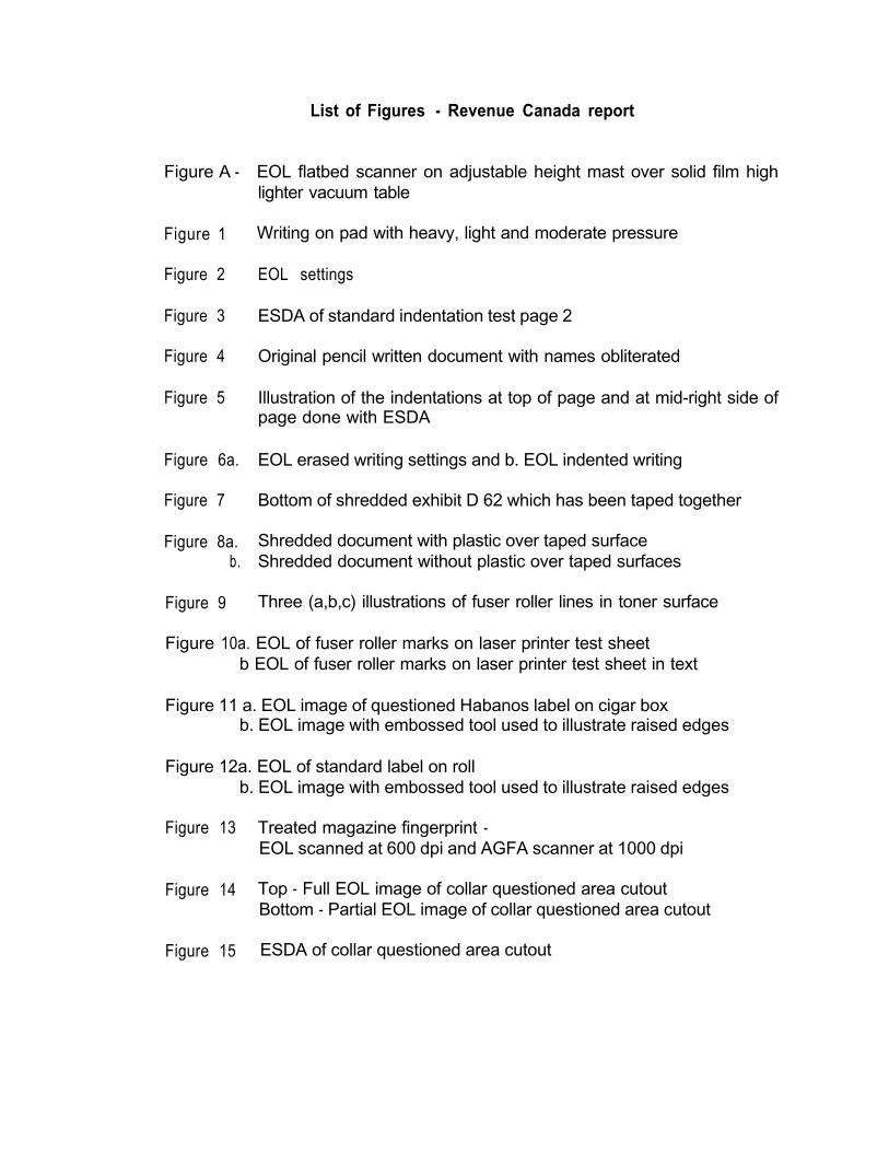
Figure A -
Figure 1
Figure 2
Figure 3
Figure 4
Figure 5
Figure 6a.
Figure 7
Figure 8a.b.
Figure 9
List of Figures - Revenue Canada report
EOL flatbed scanner on adjustable height mast over solid film highlighter vacuum table
Writing on pad with heavy, light and moderate pressure
EOL settings
ESDA of standard indentation test page 2
Original pencil written document with names obliterated
Illustration of the indentations at top of page and at mid-right side ofpage done with ESDA
EOL erased writing settings and b. EOL indented writing
Bottom of shredded exhibit D 62 which has been taped together
Shredded document with plastic over taped surfaceShredded document without plastic over taped surfaces
Three (a,b,c) illustrations of fuser roller lines in toner surface
Figure 10a. EOL of fuser roller marks on laser printer test sheetb EOL of fuser roller marks on laser printer test sheet in text
Figure 11 a. EOL image of questioned Habanos label on cigar boxb. EOL image with embossed tool used to illustrate raised edges
Figure 12a. EOL of standard label on rollb. EOL image with embossed tool used to illustrate raised edges
Figure 13 Treated magazine fingerprint -EOL scanned at 600 dpi and AGFA scanner at 1000 dpi
Figure 14 Top - Full EOL image of collar questioned area cutoutBottom - Partial EOL image of collar questioned area cutout
Figure 15 ESDA of collar questioned area cutout
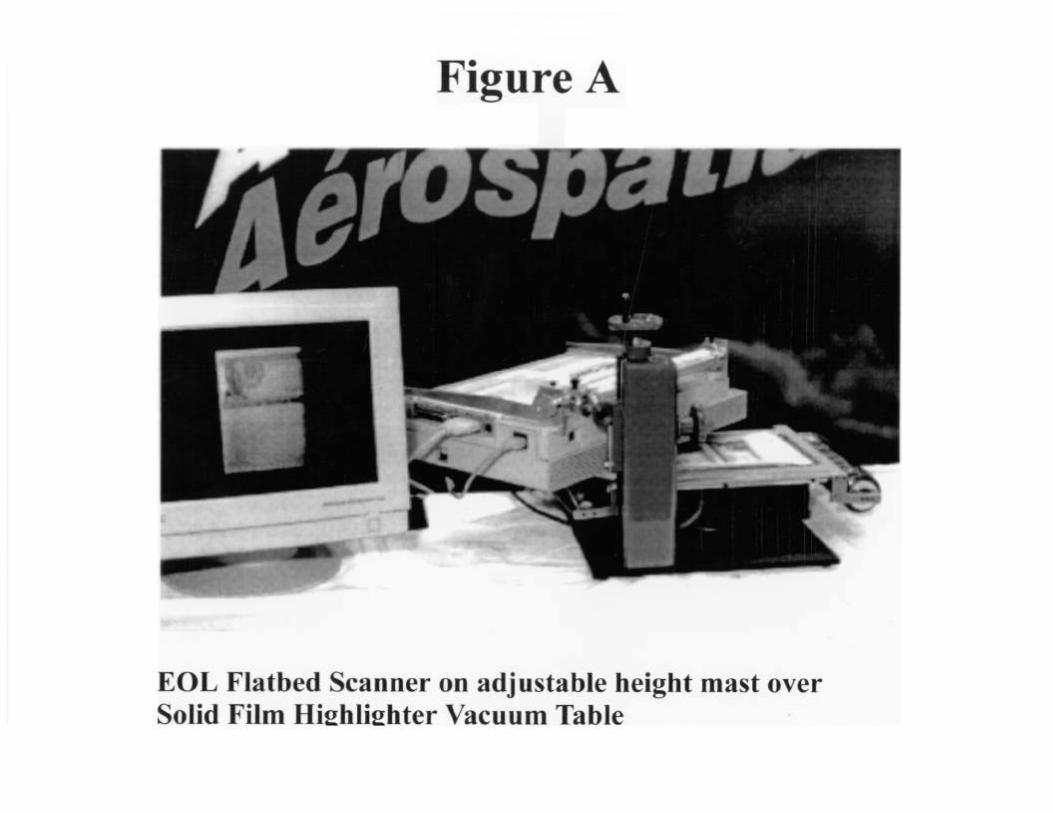
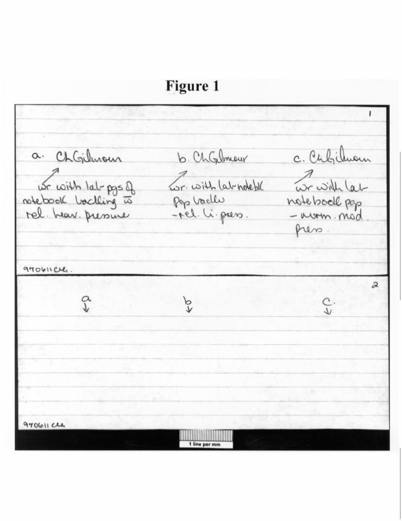
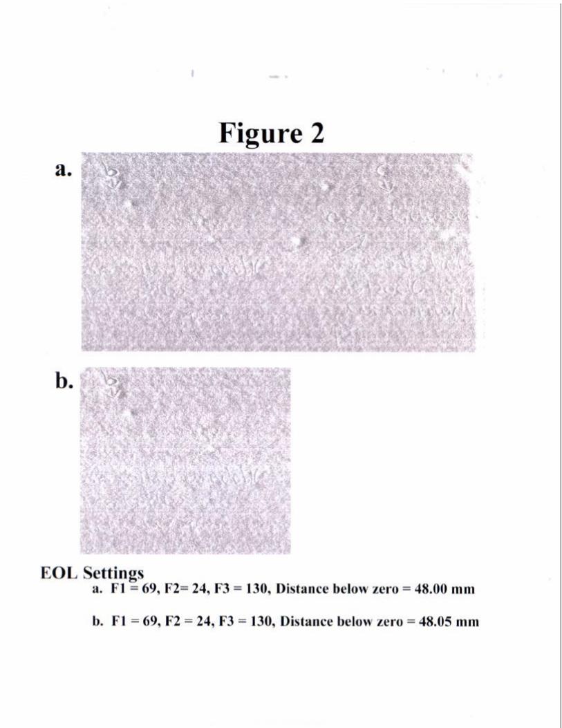
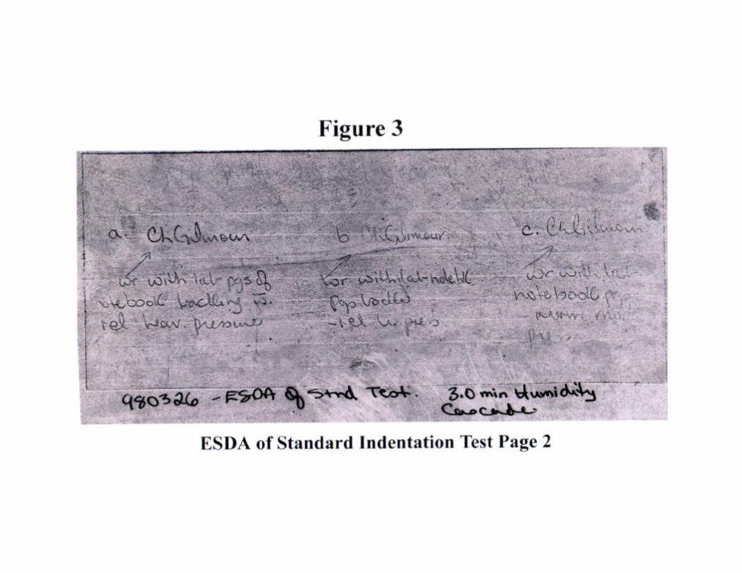
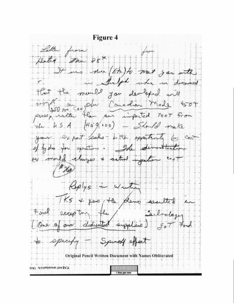
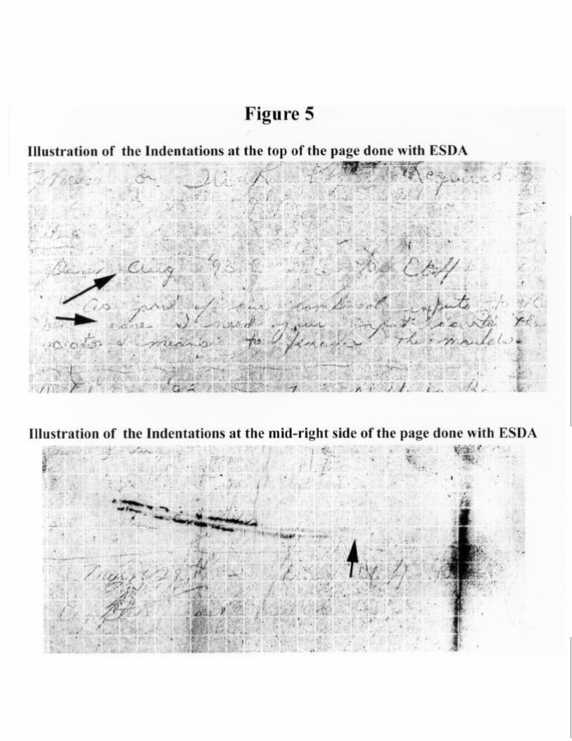
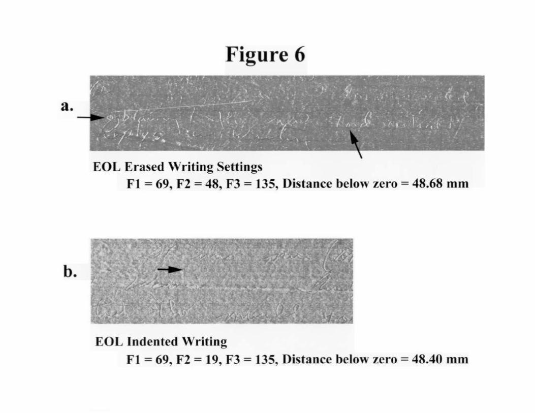
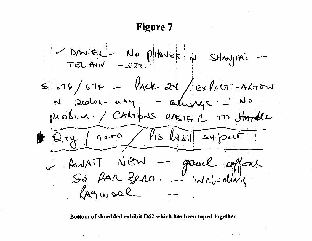
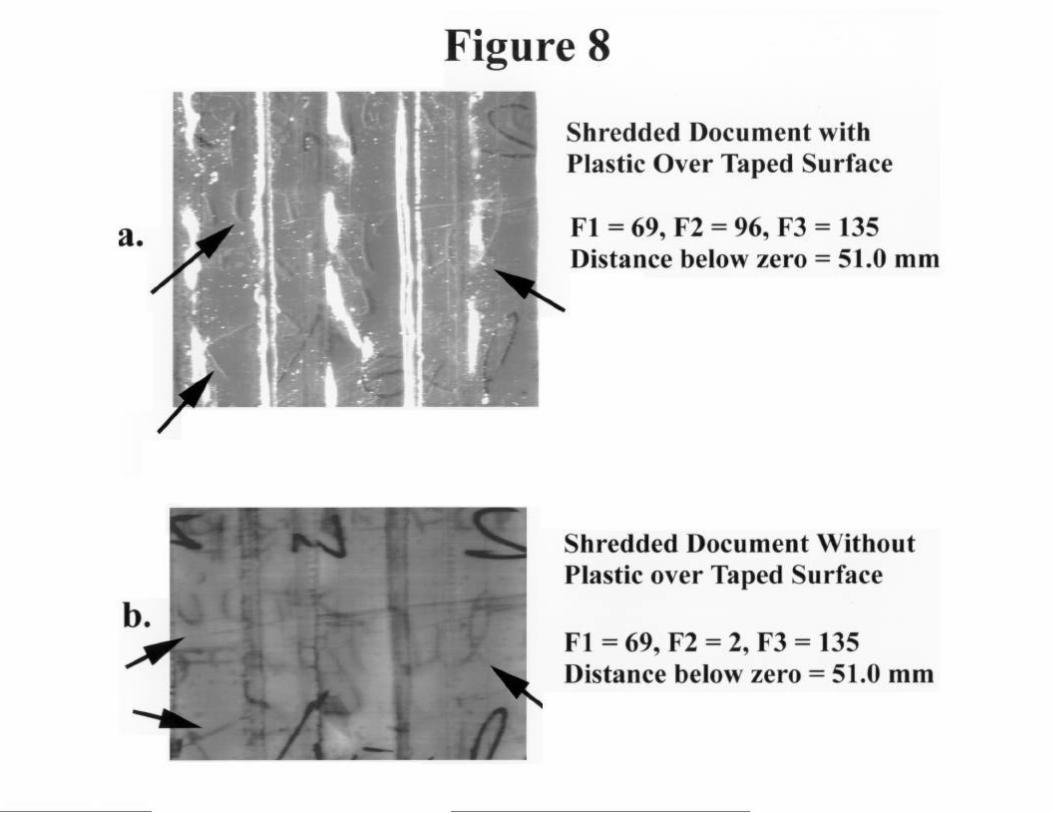
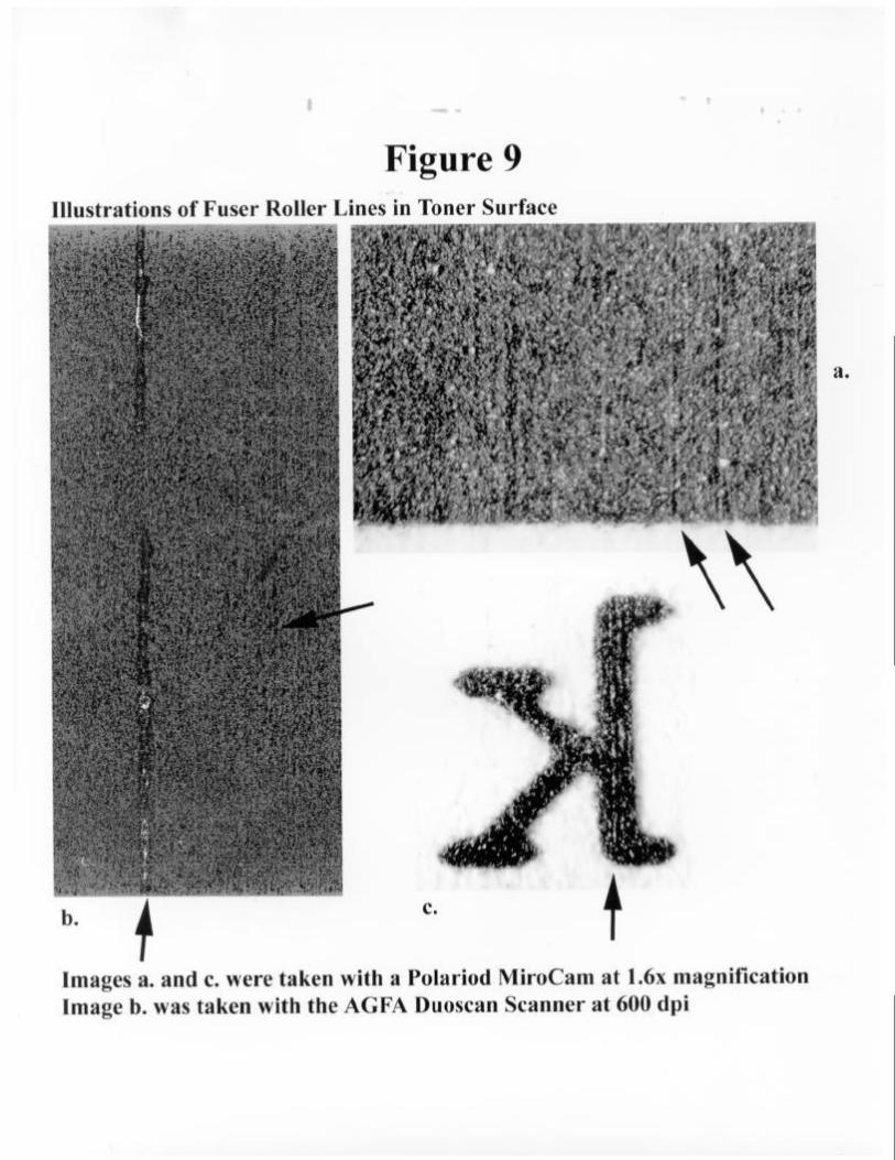
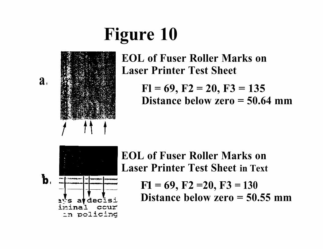
Figure 10
a .
b .
EOL of Fuser Roller Marks onLaser Printer Test Sheet
Fl = 69, F2 = 20, F3 = 135Distance below zero = 50.64 mm
EOL of Fuser Roller Marks onLaser Printer Test Sheet in Text
F1 = 69, F2 =20, F3 = 130Distance below zero = 50.55 mm


NRC-CNRC Information - The Edge of Enhanced Optical NDI TechniqueIAR Fact Sheet
NRC-CNRC Information - The Edge of Light Enhanced Optical NDI TechniqueIAR Tech Sheet
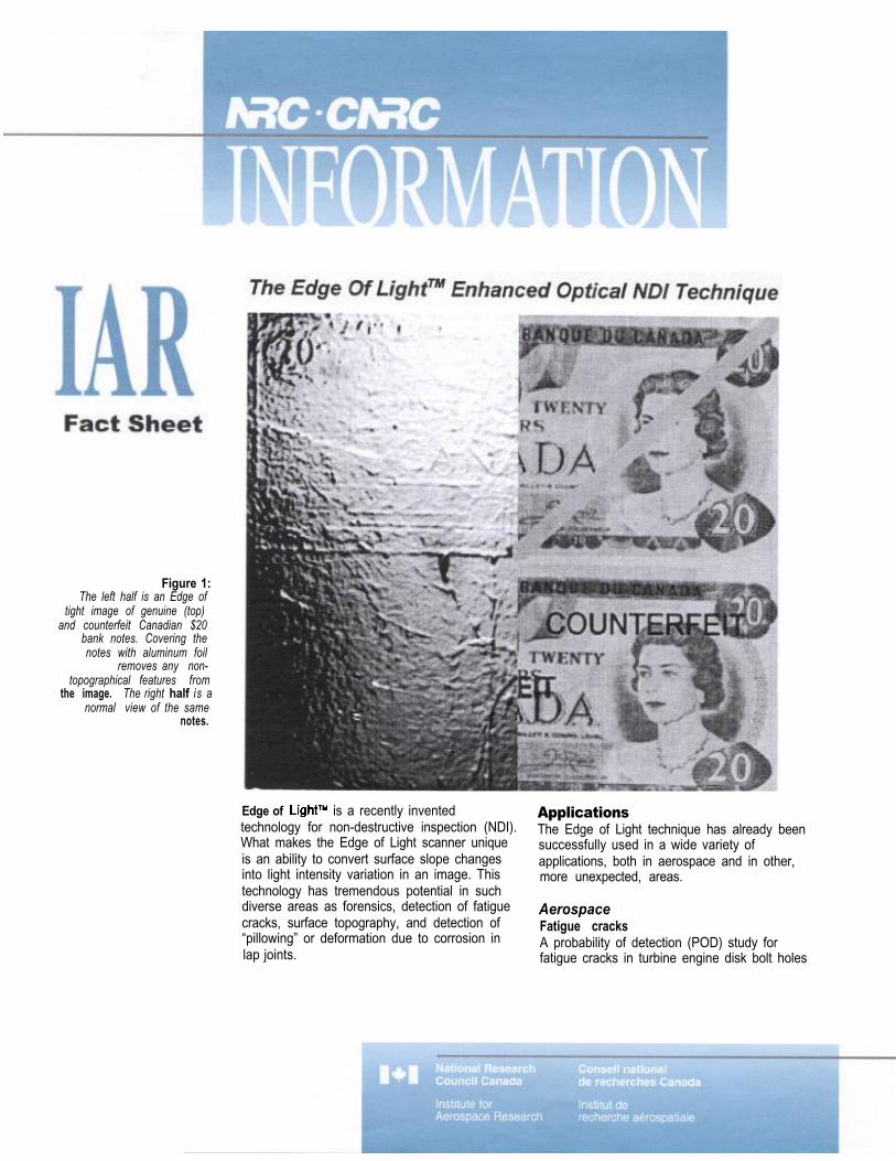
Figure 1:The left half is an Edge of
tight image of genuine (top)and counterfeit Canadian $20
bank notes. Covering thenotes with aluminum foil
removes any non-topographical features from
the image. The right half is anormal view of the same
notes.
Edge of is a recently inventedtechnology for non-destructive inspection (NDI).What makes the Edge of Light scanner uniqueis an ability to convert surface slope changesinto light intensity variation in an image. Thistechnology has tremendous potential in suchdiverse areas as forensics, detection of fatiguecracks, surface topography, and detection of“pillowing” or deformation due to corrosion inlap joints.
ApplicationsThe Edge of Light technique has already beensuccessfully used in a wide variety ofapplications, both in aerospace and in other,more unexpected, areas.
AerospaceFatigue cracksA probability of detection (POD) study forfatigue cracks in turbine engine disk bolt holes
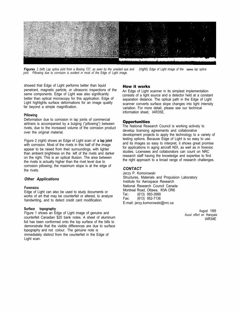
Figures 2 (left) Lap splice joint from a Boeing 727, as seen by the unaided eye and (right) Edge of Light image of the same lap splicejoint. Pillowing due to corrosion is evident in most of the Edge of Light image.
showed that Edge of Light performs better than liquidpenetrant, magnetic particle, or ultrasonic inspections of thesame components. Edge of Light was also significantlybetter than optical microscopy for this application. Edge ofLight highlights surface deformations for an image qualityfar beyond a simple magnification.
PillowingDeformation due to corrosion in lap joints of commercialairliners is accompanied by a bulging (“pillowing”) betweenrivets, due to the increased volume of the corrosion productover the original material.
Figure 2 (right) shows an Edge of Light scan of a lap jointwith corrosion. Most of the rivets in this half of the imageappear to be raised from their surroundings, with lighterthan ambient brightness on the left of the rivets and darkeron the right. This is an optical illusion. The area betweenthe rivets is actually higher than the rivet level due tocorrosion pillowing; the maximum slope is at the edge ofthe rivets.
Other Applications
ForensicsEdge of Light can also be used to study documents orworks of art that may be counterfeit or altered, to analyzehandwriting, and to detect credit card modification.
Surface topographyFigure 1 shows an Edge of Light image of genuine andcounterfeit Canadian $20 bank notes. A sheet of aluminumfoil has been conformed onto the top surface of the bills todemonstrate that the visible differences are due to surfacetopography and not colour. The genuine note isimmediately distinct from the counterfeit in the Edge ofLight scan.
How it worksAn Edge of Light scanner in its simplest implementationconsists of a light source and a detector held at a constantseparation distance. The optical path in the Edge of Lightscanner converts surface slope changes into light intensityvariation. For more detail, please see our technicalinformation sheet, IAR35E.
OpportunitiesThe National Research Council is working actively todevelop licensing agreements and collaborativedevelopment projects to apply the technology to a variety oftesting options. Because Edge of Light is so easy to useand its images so easy to interpret, it shows great promisefor applications in aging aircraft NDI, as well as in forensicstudies. Licensees and collaborators can count on NRCresearch staff having the knowledge and expertise to findthe right approach to a broad range of research challenges.
CONTACTJerzy P. KomorowskiStructures, Materials and Propulsion LaboratoryInstitute for Aerospace ResearchNational Research Council CanadaMontreal Road, Ottawa, K1A OR6Tel.: (613) 993-3999Fax: (613) 952-7136E-mail: [email protected]
August 1999Aussi offert en français
IAR34E
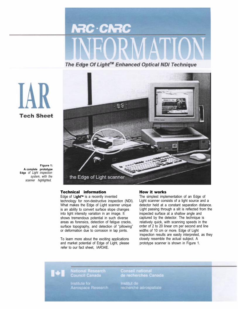
Figure 1:A complete prototype
Edge of Light inspectionsystem, with the
scanner highlighted.
Technical informationEdge of is a recently inventedtechnology for non-destructive inspection (NDI).What makes the Edge of Light scanner uniqueis an ability to convert surface slope changesinto light intensity variation in an image. Itshows tremendous potential in such diverseareas as forensics, detection of fatigue cracks,surface topography, and detection of “pillowing”or deformation due to corrosion in lap joints.
To learn more about the exciting applicationsand market potential of Edge of Light, pleaserefer to our fact sheet, IAR34E.
How it worksThe simplest implementation of an Edge ofLight scanner consists of a light source and adetector held at a constant separation distance.Light passing through a slit is reflected from theinspected surface at a shallow angle andcaptured by the detector. The technique isrelatively quick, with scanning speeds in theorder of 2 to 20 linear cm per second and linewidths of 10 cm or more. Edge of Lightinspection results are easily interpreted, as theyclosely resemble the actual subject. Aprototype scanner is shown in Figure 1.
light source opening
edge of light regions
intensity
edge of light region
3 falling slope
full illumination regions
“edge of light” regions
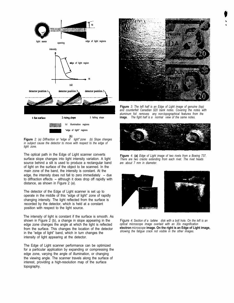
Figure 2: (a) Diffraction or “edge of light" zone (b) Slope changesin subject cause the detector to move with respect to the edge oflight zone.
The optical path in the Edge of Light scanner convertssurface slope changes into light intensity variation. A lightsource behind a slit is used to produce a rectangular bandof light on the surface of the object to be scanned. In themain zone of the band, the intensity is constant. At theedge, the intensity does not fall to zero immediately - dueto diffraction effects - although it does drop off rapidly withdistance, as shown in Figure 2 (a).
The detector of the Edge of Light scanner is set up tooperate in the middle of this “edge of light” zone of rapidlychanging intensity. The light reflected from the surface isrecorded by the detector, which is held at a constantposition with respect to the light source.
The intensity of light is constant if the surface is smooth. Asshown in Figure 2 (b), a change in slope appearing in theedge zone changes the angle at which the light is reflectedfrom the surface. This changes the location of the detectorin the “edge of light” band, which in turn changes theintensity of light appearing at the detector.
Figure 3: The left half is an Edge of Light image of genuine (top)and counterfeit Canadian $20 bank notes. Covering the notes withaluminum foil removes any non-topographical features from theimage. The fight half is a normal view of the same notes.
Figure 4: (a) Edge of Light image of two rivets from a Boeing 737.There are two cracks extending from each rivet. The rivet headsare about 7 mm in diameter.
Figure 4: Section of a turbine disk with a bolt hole. On the left is anoptical microscope image overlaid with an 30x magnificationelectron microscope image. On the right is an Edge of Light image,showing the fatigue crack not visible in the other images.
The Edge of Light scanner performance can be optimizedfor a particular application by expanding or compressing theedge zone, varying the angle of illumination, or changingthe viewing angle. The scanner travels along the surface ofinterest, providing a high-resolution map of the surfacetopography.
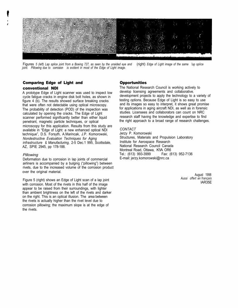
Figures 5 (left) Lap splice joint from a Boeing 727, as seen by the unaided eye and (right) Edge of Light image of the same lap splicejoint. Pillowing due to corrosion is evident in most of the Edge of Light image.
Comparing Edge of Light andconventional NDIA prototype Edge of Light scanner was used to inspect lowcycle fatigue cracks in engine disk bolt holes, as shown infigure 4 (b). The results showed surface breaking cracksthat were often not detectable using optical microscopy.The probability of detection (POD) of the inspection wascalculated by opening the cracks. The Edge of Lightscanner performed significantly better than either liquidpenetrant, magnetic particle techniques, or opticalmicroscopy for this application. Results from this study areavailable in “Edge of Light: a new enhanced optical NDItechnique”, D.S. Forsyth, A.Marincak, J.P. Komorowski,Nondestructive Evaluation Techniques for Aginginfrastructure & Manufacturing, 2-5 Dec.1 995, Scottsdale,AZ, SPIE 2945, pp 178-188.
PillowingDeformation due to corrosion in lap joints of commercialairliners is accompanied by a bulging (“pillowing”) betweenrivets, due to the increased volume of the corrosion productover the original material.
Figure 5 (right) shows an Edge of Light scan of a lap jointwith corrosion. Most of the rivets in this half of the imageappear to be raised from their surroundings, with lighterthan ambient brightness on the left of the rivets and darkeron the right. This is an optical illusion. The area betweenthe rivets is actually higher than the rivet level due tocorrosion pillowing; the maximum slope is at the edge ofthe rivets.
OpportunitiesThe National Research Council is working actively todevelop licensing agreements and collaborative.development projects to apply the technology to a variety oftesting options. Because Edge of Light is so easy to useand its images so easy to interpret, it shows great promisefor applications in aging aircraft NDI, as well as in forensicstudies. Licensees and collaborators can count on NRCresearch staff having the knowledge and expertise to findthe right approach to a broad range of research challenges.
CONTACTJerzy P. KomorowskiStructures, Materials and Propulsion LaboratoryInstitute for Aerospace ResearchNational Research Council CanadaMontreal Road, Ottawa, K1A OR6Tel.: (613) 993-3999 Fax: (613) 952-7136E-mail: [email protected]
August 1998Aussi offert en français
IAR35E