cpe300: digital system architecture and design
TRANSCRIPT
http://www.egr.unlv.edu/~b1morris/cpe300/
CPE300: Digital System
Architecture and Design Fall 2011
MW 17:30-18:45 CBC C316
Pipelining
11142011

Outline
• Review I/O
• Chapter 5 Overview
• Pipelining
• Pipelining Hazards
2

Review of I/O • I/O subsystems appear to programmer as a part of memory
(memory-mapped I/O) ▫ Special characteristics of data location, transfer, and
synchronization make it different • Combination of hardware and software protocols guarantee
correct data transfer ▫ Programmed I/O – uses an instruction to begin transfer and polls ▫ Interrupt-driven I/O – uses exception handling to service I/O ▫ DMA – interface allows device to control memory bus like the
processor • Data within processor and outside in devices have different
characteristics that may require data format change (serial/parallel)
• I/O is more error prone than CPU hence requires error detection and/or correction
3
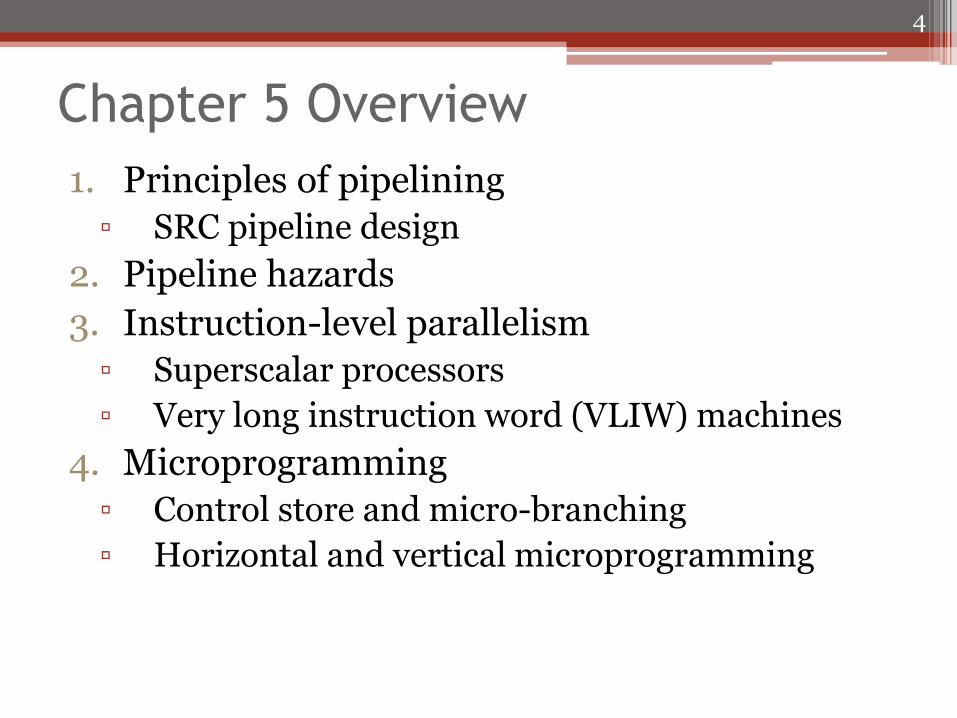
Chapter 5 Overview
1. Principles of pipelining
▫ SRC pipeline design
2. Pipeline hazards
3. Instruction-level parallelism
▫ Superscalar processors
▫ Very long instruction word (VLIW) machines
4. Microprogramming
▫ Control store and micro-branching
▫ Horizontal and vertical microprogramming
4

Pipelining • Process of issuing a new instruction before the previous
one has completed execution ▫ Favorite technique for RISC processors ▫ Hide latency of instruction execution (multiple clock cycles
for a single instruction) • Goal to keep equipment busy as much of the time as
possible ▫ Total throughput may be increased by decreasing the
amount of work done at a given stage and increasing the number of stages (simple tasks to accomplish instruction execution)
• Consequences for fetch-execute cycle ▫ Previous instruction not guaranteed to be completed before
next operation begins ▫ Results of previous operation not free available at next
operation
5

Industrial Manufacturing Pipeline
Execution Order
• 5
• 4
• 3
• 2
• 1
Only highlighted step is active at a time
6

Industrial Manufacturing Pipeline
Execution Order
• 5 – fetch instruction from memory
• 4 – operands (r4, addr1) extracted
• 3 – operands fetched and added in ALU
• 2 – idle, no memory access is required
• 1 – results written to r3
Only highlighted step is active at a time
7
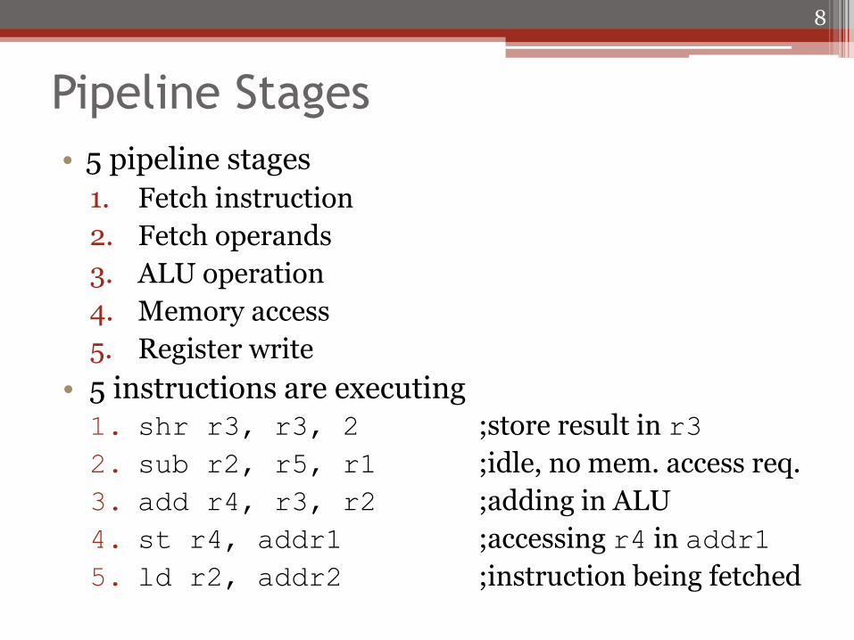
Pipeline Stages
• 5 pipeline stages
1. Fetch instruction
2. Fetch operands
3. ALU operation
4. Memory access
5. Register write
• 5 instructions are executing 1. shr r3, r3, 2 ;store result in r3
2. sub r2, r5, r1 ;idle, no mem. access req.
3. add r4, r3, r2 ;adding in ALU
4. st r4, addr1 ;accessing r4 in addr1
5. ld r2, addr2 ;instruction being fetched
8

Pipelining Instruction Processing
• All 5 instruction in execution at the same time • Assume instructions move one stage per clock tick
(exceptions exist) ▫ Every instruction takes 5 clock ticks to complete ▫ Instruction completes every clock tick
• Pipeline stages shown top to bottom in order traversed by one instruction ▫ Instructions listed in order they are fetched (opposite
pipeline direction)
• Performance issues ▫ Latency – time to process individual instruction ▫ Bandwidth – instructions/second ▫ Trade-off: higher latency for improved bandwidth
9

Inter-Instruction Dependence • Execution of some instructions may depend on
completion of other instructions in pipeline ▫ 0x100 add r0, r2, r4 ▫ 0x104 sub r3, r0, r1
• “Stall” pipeline ▫ Stop execution of early stages while later ones
complete processing • “Forward” data
▫ Detect register dependencies and make register value available without waiting for register write
• Restrict instruction set usage for memory access (harder to deal with than registers) ▫ Branch delay slot ▫ Load delay slot
10

Branch and Load Delay
• Instructions not changed, just how the operate together
• Branch delay ▫ brz r2, r3
▫ add r6, r7, r8 ;instruction always executed
▫ st r6, addr1 ;only done if r3≠0
• Load delay ▫ ld r2, addr
▫ add r5, r1, r2 ;uses old value of r2
▫ shr r1, r1, 4
▫ sub r6, r8, r2 ;uses r2 val loaded from addr
11

Characteristics of Pipelined Processor Design
• Main memory must operate in single cycle ▫ Use fast (expensive) memory ▫ Usually accomplished with cache (Chapter 7)
• Instruction and data memory must appear separate ▫ Harvard architecture has separate instruction and data
memories ▫ Usually done with separate caches ▫ Need to fetch at same time as load/store
• Few buses are used ▫ Typical connections are point to point ▫ Some few-way multiplexors are used
• Data is latched in pipeline registers (temporary register storage) at each pipeline stage
• ALU operations take 1 clock cycle ▫ Specifically shift (barrel shifter)
12

Pipelining Design Technique
• All instructions must fit into common pipeline stage structure
1. Categorize instructions into classes
▫ Register transfer characteristics/behavior
▫ Data movement, ALU, Branch
2. Map instruction classes to pipeline datapath
3. Add control signals to manage instruction flow
4. Design hardware to handle data dependencies
13

SRC Adaption for Pipelined Execution
• 5 Stage pipeline
1. Instruction fetch
2. Decode and operand access
3. ALU operations
4. Data memory access
5. Register write
• Load/store, ALU, and branch instructions organized to fit this pattern
14
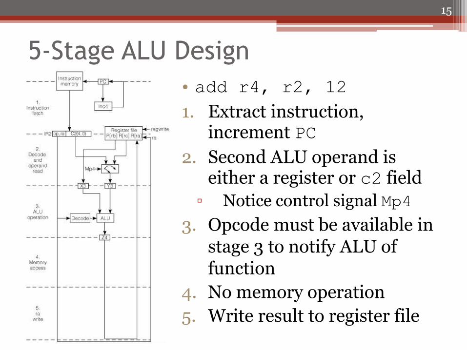
5-Stage ALU Design
• add r4, r2, 12
1. Extract instruction, increment PC
2. Second ALU operand is either a register or c2 field
▫ Notice control signal Mp4
3. Opcode must be available in stage 3 to notify ALU of function
4. No memory operation
5. Write result to register file
15

Pipeline Control Signals
• The logic equations are based on the instruction in the stage where they are used
• Digit appended to logic signal name to specify stage it is computed ▫ regwrite5 is true when the opcode in stage 5 is load5 ladr5 brl5alu5 All signals are determined from op5
16
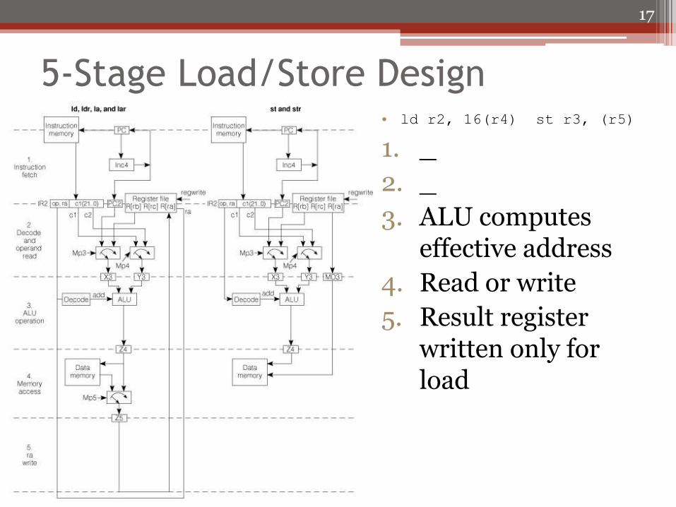
5-Stage Load/Store Design • ld r2, 16(r4) st r3, (r5)
1. _
2. _
3. ALU computes effective address
4. Read or write
5. Result register written only for load
17

5-Stage Branch Design
• br r31
1. _
2. New PC value known in stage 2 not in stage 1
3. None
4. None
5. Only branch and link does a register write
18

SRC Pipeline Registers and RTN
• Pipeline registers pass info from stage to stage
• RTN specifies output register values in terms of stage register values
19

Global State for Pipelined SRC
• Pipeline registers have state information solely for the corresponding stage
• Global state does not belong to any pipeline stage – shared by all
▫ PC
Accessed in stage 1 and stage 2 on branch
▫ General registers
▫ Instruction memory
Accessed in stage 1
▫ Data memory
Accessed in stage 4
20

Access Restrictions for Global State
• Separate instruction and data memories needed
▫ Two memory accesses can occur simultaneously
▫ Load/store accesses data memory in stage 4
▫ Stage 1 accesses an instruction
• Registers read and write at same time
▫ 2 operands may be needed in stage 2
▫ Register could be written as result in stage 5
• PC increment at stage 1 must be overridden by a successful branch in stage 2
21

Pipeline Datapath and Control • Multiplexer
control stressed in figure
• Most control signals sown and given values
22

Example Pipeline Propogation
23
• Assume R[11] = 512 when brl instruction
executed
• R[6]=4 and R[8]=5
• R[5]=16 for ld
• R[12]=23 for str
100 add r4, r6, r8 ;R[4]R[6]+R[8]
104 ld r7, 128(r5) ;R[7]M[R[5]+128]
108 brl r9, r11, 001 ;PCR[11]: R[9]PC
112 str r12, 32 M[PC+32]R[12]
…
512 sub … ;next instruction

Cycle 1: add enters Pipeline
• PC incremented to 104
24
100 add r4, r6, r8

Cycle 2: ld Enters Pipeline
• Add operands are fetched in stage 2
• add operands are fetched in
stage 2
25
104 ld r7, 128(r5)
100 add r4, r6, r8

Cycle 3: brl Enters Pipeline
• add performs arithmetic in
stage 3
26
108 brl r9, r11, 001
104 ld r7, 128(r5)
100 add r4, r6, r8
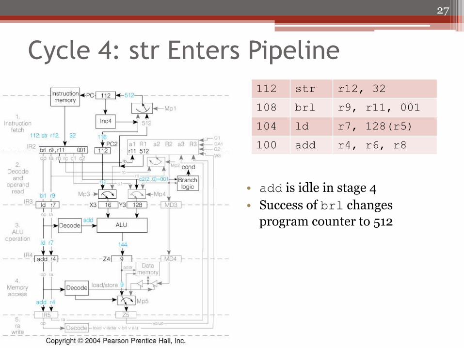
Cycle 4: str Enters Pipeline
• add is idle in stage 4
• Success of brl changes
program counter to 512
27
112 str r12, 32
108 brl r9, r11, 001
104 ld r7, 128(r5)
100 add r4, r6, r8

Cycle 5: sub Enters Pipeline
• add completes in stage 5
• sub is fetched from location
512 after the successful branch
28
512 sub …
112 str r12, 32
108 brl r9, r11, 001
104 ld r7, 128(r5)
100 add r4, r6, r8

Functions of SRC Pipeline Registers • Registers between stages 1 and 2
▫ IR2 holds the full instruction including any register fields and constants
▫ PC2 holds the incremented PC from instruction fetch • Registers between stages 2 and 3
▫ IR3 holds opcode and ra (needed in stage 5) ▫ X3 holds PC or a register value (for link or first ALU operand) ▫ Y3 holds c1, c2, or register value for second ALU operand ▫ MD3 is used for a register value to be stored in memory
• Registers between stages 3 and 4 ▫ IR4 holds opcode and ra ▫ Z4 has memory address or result register value ▫ MD4 has value to be stored in data memory
• Registers between stages 4 and 5 ▫ IR5 holds opcode and destination registers number ra ▫ Z5 has value to be stored in destination register
ALU result, PC link value, or fetched data
29

Functions of SRC Pipeline Stages • Stage 1: fetches instruction
▫ PC incremented or replaced by successful branch in stage 2 • Stage 2: decodes instruction and gets operands
▫ Load/store gets operands for address computation ▫ Store gets register value to be stored as 3rd operand ▫ ALU operation gets 2 registers or register and constant
• Stage 3: performs ALU operation ▫ Calculates effective address or does arithmetic/logic ▫ May pass through link PC or value to be stored in memory
• Stage 4: accesses data memory ▫ Passes Z4 to Z5 unchanged for non-memory instructions ▫ Load fills Z5 from memory ▫ Store uses address from Z4 and data from MD4 (no longer needed)
• Stage 5: writes result register ▫ Z5 contains value to be written, which can be ALU result, effective
address, PC link value, or fetched data ▫ ra field always specifies result register in SRC
30

Pipeline Hazards
• Deterministic events that are a side-effect of having instructions in pipeline
▫ Parallel execution
▫ Instruction dependence – instruction depends on result of previous instruction that is not yet completely executed
• Two categories of hazards
▫ Data hazards – incorrect use of old and new data
▫ Branch hazards – fetch of wrong instruction on a change in the PC
31

Branch Hazards
• Branch targets determined in stage 2 ▫ Instruction following the branch instruction will enter
the pipeline ▫ Branch delay states following instruction gets executed
without regard for branch action Branch delay slot instruction executed before branch is
taken
• Branch prediction ▫ Improve pipeline performance by trying to guess if the
branch will be taken Keep information to tell if instruction already seen and
PC values after execution
Delay only when prediction is wrong
▫ Lots effort in designing prediction schemes
32

Data Hazards
• Incorrect use of old and new data • Read after write (RAW) hazard
▫ Flow dependence – instruction uses data produced by a previous one
• Write after read (WAR) hazard ▫ Anti-dependence – instruction writes a new value
over one that is still needed by a previous instruction
• Write after write (WAW) hazard ▫ Output dependence – two parallel instructions
write the same register and must do it in the order they were issued
33

Detecting Hazards
• Pairs of instructions must be considered to detect hazards
• Data is normally available after being written to a register ▫ Use data forwarding to make it available as early as
stage it was produced Stage 3 output for ALU results
Stage 4 for memory fetch
▫ Receive data as late as stage in which they are used Operands normally needed in stage 2
Stage 2 for branch target
Stage 3 for ALU operands and address modifier
Stage 4 for stored register
34

Data Hazards in SRC
• All data memory access occurs in stage 4 meaning all memory reads and writes are sequential and do not cause hazards
• Registers written in the last stage
▫ WAW and WAR hazards do not occur
▫ Two writes occur in order issued
▫ Write always follows a previously issued read
• Only RAW hazards exist
▫ Values written to register at end of stage 5 may be needed by a following instruction at beginning of stage 2
35

Possible Solutions to Register Data Hazard
• Detection ▫ Machine manual could give rules specifying a
dependent instruction must have minimum number of steps from instruction it depends on
▫ Can be done by compiler but generally too restrictive
▫ Dependence on following stage can be detected since operation and operands known at each stage
• Correction (hardware) ▫ Dependent instruction “stalled” to allow those
ahead in the pipeline to complete ▫ Result “forwarded” to an earlier stage without
waiting for a register write
36

RAW, WAW, and WAR Hazards
• RAW hazards due to causality ▫ Cannot use value before it has been produced ▫ Requires data forwarding
• WAW and WAR hazards can only occur when instructions executed in parallel or out of order ▫ Not possible in SRC ▫ Arise because registers have the same name
Can be fixed by renaming one of the registers Delay the update of a register until appropriate value
produced
37

Instruction Pair Hazard Interaction
• 4/1 indicates the normal/forwarded instruction separation ▫ 4 instruction separation normally ▫ 1 indicates only a single stage of separation (1 instruction) ▫ Many have 4/1 and gives rise to approximately 1 instruction
per clock cycle
38
alu load ladr brl
6/4 6/5 6/4 6/2
alu 2/3 4/1 4/2 4/1 4/1
load 2/3 4/1 4/2 4/1 4/1
ladr 2/3 4/1 4/2 4/1 4/1
store 2/3 4/1 4/2 4/1 4/1
branch 2/2 4/2 4/3 4/2 4/1
Read from register file Stage normally/latest needed
Write to register file Stage data normally/earliest available
Delays Unavoidable by Forwarding
• Loaded values cannot be available to next instruction even with forwarding ▫ Restrict compiler from putting dependent instruction
in position right after load (next 2 positions for branch)
• Target register cannot be forwarded to branch from immediately preceding instruction ▫ Code restricted so branch target is not changed by
instruction preceding branch (previous 2 instructions if load from memory)
▫ Not to be confused with branch delay slot Branch delay – dependence fetch on branch
This is branch instruction dependent on some instruction before it
39

Stalling Pipeline on Hazard Detection
• Pipeline can be stalled to inhibit earlier stages and allowing later stages to proceed
• Stage is inhibited by pause signal
▫ Turn off clock to that stage to prevent registers from changing
• Must deliver something to clear pipeline after the paused stage
▫ Stage 3 must have do something after 1 and 2 paused
▫ Use nop
40

Stall from ALU-ALU Dependence
41

Data Forwarding Hardware • Hazard detection and
forwarding units added to pipeline
• Multiplexers allow forwarding of Z4 or Z5 to either the X or Y
inputs of ALU
• rb and rc needed from stage 3 for detection
42

Restrictions After Forwarding 1. Branch delay slot
▫ Instruction after branch is always executed no matter if the branch succeeds or not
2. Load delay slot ▫ Register loaded from memory cannot
be used as operand in the next instruction
▫ Register loaded from memory cannot be used as a branch target for the next 2 instructions
3. Branch target ▫ Results register of alu or ladr
instruction cannot be used as a branch target by next instruction
43
br r4
add . . .
ld r4, 4(r5)
nop
neg r6, r4
ld r0, 1000
nop
nop
br r0
not r0, r1
nop
br r0