cp5 - pulspower.com
TRANSCRIPT
CP5.121
CP-Series 12V, 10A, 120W, SINGLE PHASE INPUT
Aug 2021 / Rev. 1.2 DS-CP5.121-EN All values are typical figures specified at 230Vac, 50Hz input voltage, 12V 10A output load, 25°C ambient and after a 5 minutes run-in time unless otherwise noted.
www.pulspower.com Phone +49 89 9278 0 Germany 1/28
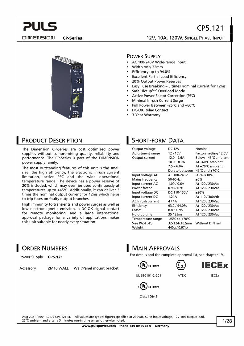
POWER SUPPLY AC 100-240V Wide-range Input Width only 32mm Efficiency up to 94.0% Excellent Partial Load Efficiency 20% Output Power Reserves Easy Fuse Breaking – 3 times nominal current for 12ms Safe HiccupPLUS Overload Mode Active Power Factor Correction (PFC) Minimal Inrush Current Surge Full Power Between -25°C and +60°C DC-OK Relay Contact 3 Year Warranty
PRODUCT DESCRIPTION The Dimension CP-Series are cost optimized power supplies without compromising quality, reliability and performance. The CP-Series is part of the DIMENSION power supply family.
The most outstanding features of this unit is the small size, the high efficiency, the electronic inrush current limitation, active PFC and the wide operational temperature range. The device has a power reserve of 20% included, which may even be used continuously at temperatures up to +45°C. Additionally, it can deliver 3 times the nominal output current for 12ms which helps to trip fuses on faulty output branches.
High immunity to transients and power surges as well as low electromagnetic emission, a DC-OK signal contact for remote monitoring, and a large international approval package for a variety of applications makes this unit suitable for nearly every situation.
SHORT-FORM DATA
Output voltage DC 12V Nominal Adjustment range 12 - 15V Factory setting 12.0V Output current 12.0 - 9.6A Below +45°C ambient 10.0 – 8.0A At +60°C ambient 7.5 – 6.0A At +70°C ambient Derate between +45°C and +70°C Input voltage AC AC 100-240V -15%/+10% Mains frequency 50-60Hz ±6% Input current AC 1.09 / 0.6A At 120 / 230Vac Power factor 0.98 / 0.91 At 120 / 230Vac Input voltage DC DC 110-150V ±20% Input current DC 1.21A At 110 / 300Vdc AC Inrush current 4 / 4A At 120 / 230Vac Efficiency 93.2 / 94.0% At 120 / 230Vac Losses 8.8 / 7.7W At 120 / 230Vac Hold-up time 35 / 35ms At 120 / 230Vac Temperature range -25°C to +70°C Size (WxHxD) 32x124x102mm Without DIN rail Weight 440g / 0.97lb
ORDER NUMBERS Power Supply CP5.121
Accessory ZM10.WALL Wall/Panel mount bracket
MAIN APPROVALS For details and the complete approval list, see chapter 19.
UL 610101-2-201 ATEX IECEx
Class I Div 2
CP5.121
CP-Series 12V, 10A, 120W, SINGLE PHASE INPUT
Aug 2021 / Rev. 1.2 DS-CP5.121-EN All values are typical figures specified at 230Vac, 50Hz input voltage, 12V 10A output load, 25°C ambient and after a 5 minutes run-in time unless otherwise noted.
www.pulspower.com Phone +49 89 9278 0 Germany 2/28
INDEX
Page Page 1. Intended Use ............................................................. 3 2. Installation Instructions ............................................ 3 3. AC-Input .................................................................... 5 4. DC-Input .................................................................... 7 5. Input Inrush Current ................................................. 7 6. Output ....................................................................... 8 7. Hold-up Time .......................................................... 10 8. DC-OK Relay Contact .............................................. 10 9. Efficiency and Power Losses ................................... 11 10. Functional Diagram ................................................ 12 11. Front Side and User Elements ................................ 12 12. Connection Terminals............................................. 13 13. Lifetime Expectancy................................................ 14 14. MTBF ........................................................................ 14 15. EMC .......................................................................... 15 16. Environment ........................................................... 16 17. Safety and Protection Features ............................. 17
18. Dielectric Strength.................................................. 18 19. Approved, Fulfilled or Tested Standards .............. 19 20. Regulatory Product Compliance............................ 20 21. Physical Dimensions and Weight .......................... 21 22. Accessories .............................................................. 22
22.1. ZM10.WALL - Wall/Panel Mount Bracket .... 22 22.2. YR20.242 - Redundancy Module .................. 23
23. Application Notes ................................................... 24 23.1. Peak Current Capability ................................ 24 23.2. Charging of Batteries ................................... 25 23.3. Series Operation ........................................... 25 23.4. Parallel Use to Increase Output Power........ 25 23.5. Parallel Use for Redundancy ........................ 26 23.6. Operation on Two Phases ............................ 27 23.7. Use in a Tightly Sealed Enclosure ................ 27 23.8. Mounting Orientations ................................ 28
The information given in this document is correct to the best of our knowledge and experience at the time of publication. If not expressly agreed otherwise, this information does not represent a warranty in the legal sense of the word. As the state of our knowledge and experience is constantly changing, the information in this data sheet is subject to revision. We therefore kindly ask you to always use the latest issue of this document (available under www.pulspower.com).
No part of this document may be reproduced or utilized in any form without our prior permission in writing.
Packaging and packaging aids can and should always be recycled. The product itself may not be disposed of as domestic refuse.
TERMINOLOGY AND ABREVIATIONS PE and symbol PE is the abbreviation for Protective Earth and has the same meaning as the symbol .
Earth, Ground This document uses the term “earth” which is the same as the U.S. term “ground”.
t.b.d. To be defined, value or description will follow later.
AC 230V A figure displayed with the AC or DC before the value represents a nominal voltage with standard tolerances (usually ±15%) included. E.g.: DC 12V describes a 12V battery disregarding whether it is full (13.7V) or flat (10V)
230Vac A figure with the unit (Vac) at the end is a momentary figure without any additional tolerances included.
50Hz vs. 60Hz As long as not otherwise stated, AC 230V parameters are valid at 50Hz mains frequency.
may A key word indicating flexibility of choice with no implied preference.
shall A key word indicating a mandatory requirement.
should A key word indicating flexibility of choice with a strongly preferred implementation.
CP5.121
CP-Series 12V, 10A, 120W, SINGLE PHASE INPUT
Aug 2021 / Rev. 1.2 DS-CP5.121-EN All values are typical figures specified at 230Vac, 50Hz input voltage, 12V 10A output load, 25°C ambient and after a 5 minutes run-in time unless otherwise noted.
www.pulspower.com Phone +49 89 9278 0 Germany 3/28
1. INTENDED USE This device is designed for installation in an enclosure and is intended for commercial use, such as in industrial control, process control, monitoring, measurement, Audio/Video, information or communication equipment or the like.
Do not use this device in equipment, where malfunctioning may cause severe personal injury or threaten human life without additional appropriate safety devices, that are suited for the end-application.
If this device is used in a manner outside of its specification, the protection provided by the device may be impaired.
2. INSTALLATION INSTRUCTIONS
WARNING Risk of electrical shock, fire, personal injury or death. - Turn power off before working on the device and protect against inadvertent re-powering. - Do not open, modify or repair the device. - Use caution to prevent any foreign objects from entering into the housing. - Do not use in wet locations or in areas where moisture or condensation can be expected. - Do not touch during power-on, and immediately after power-off. Hot surface may cause burns. Obey the following installation instructions:
This device may only be installed and put into operation by qualified personnel.
This device does not contain serviceable parts. The tripping of an internal fuse is caused by an internal defect.
If damage or malfunction should occur during installation or operation, immediately turn power off and send unit to the factory for inspection.
Install device in an enclosure providing protection against electrical, mechanical and fire hazards.
Install the device onto a DIN rail according to EN 60715 with the input terminals on the bottom and the output terminals on the top of the device. Other mounting orientations require a reduction in output current.
Make sure that the wiring is correct by following all local and national codes. Use appropriate copper cables that are designed for a minimum operating temperature of 60°C for ambient temperatures up to +45°C, 75°C for ambient temperatures up to +60°C and 90°C for ambient temperatures up to +70°C.
Ensure that all strands of a stranded wire enter the terminal connection. Use ferrules for wires on the input terminals. Unused screw terminals should be securely tightened.
The device is designed for pollution degree 2 areas in controlled environments. No condensation or frost is allowed.
The enclosure of the device provides a degree of protection of IP20. The housing does not provide protection against spilled liquids.
The isolation of the device is designed to withstand impulse voltages of overvoltage category III according to IEC 60664-1.
The device is designed as “Class of Protection I” equipment according to IEC 61140. Do not use without a proper PE (Protective Earth) connection.
The device is suitable to be supplied from TN, TT or IT mains networks. The continuous voltage between the input terminal and the PE potential must not exceed 300Vac.
The input can also be powered from batteries or similar DC sources. The continuous voltage between the supply voltage and the PE/ground potential must not exceed 360Vdc.
A disconnecting means shall be provided for the input of the device.
The device is designed for convection cooling and does not require an external fan. Do not obstruct airflow and do not cover ventilation grid!
The device is designed for altitudes up to 5000m (16400ft). Above 2000m (6560ft) a reduction in output current and over voltage category is required.
CP5.121
CP-Series 12V, 10A, 120W, SINGLE PHASE INPUT
Aug 2021 / Rev. 1.2 DS-CP5.121-EN All values are typical figures specified at 230Vac, 50Hz input voltage, 12V 10A output load, 25°C ambient and after a 5 minutes run-in time unless otherwise noted.
www.pulspower.com Phone +49 89 9278 0 Germany 4/28
Keep the following minimum installation clearances: 40mm on top, 20mm on the bottom, 5mm left and right side. Increase the 5mm to 15mm in case the adjacent device is a heat source. When the device is permanently loaded with less than 50%, the 5mm can be reduced to zero.
The device is designed, tested and approved for branch circuits up to 32A (IEC) and 30A (UL) without additional protection device. If an external fuse is utilized, do not use circuit breakers smaller than 6A B- or C-Characteristic to avoid a nuisance tripping of the circuit breaker.
The maximum surrounding air temperature is +70°C (+158°F). The operational temperature is the same as the ambient or surrounding air temperature and is defined 2cm below the device.
The device is designed to operate in areas between 5% and 95% relative humidity.
Installation Instructions for Hazardous Location Areas
The device is suitable for use in Class I Division 2 Groups A, B, C, D locations and for use in Group II Category 3 (Zone 2) environments.
Classification: ATEX: EPS 19 ATEX 1 201 X, II 3G EX ec nC IIC T4 Gc / IECEx EPS 19.0078X
WARNING EXPLOSION HAZARDS!
Use only in standard vertical mounting orientation with the input terminals on bottom of the unit. Substitution of components may impair suitability for this environment.
Do not disconnect the device or operate the voltage adjustment unless power has been switched off or the area is known to be non-hazardous.
A suitable enclosure must be provided for the end product which has a minimum protection of IP54 and fulfils the requirements of the EN 60079-0.
CP5.121
CP-Series 12V, 10A, 120W, SINGLE PHASE INPUT
Aug 2021 / Rev. 1.2 DS-CP5.121-EN All values are typical figures specified at 230Vac, 50Hz input voltage, 12V 10A output load, 25°C ambient and after a 5 minutes run-in time unless otherwise noted.
www.pulspower.com Phone +49 89 9278 0 Germany 5/28
3. AC-INPUT The device is suitable to be supplied from TN, TT or IT mains networks with AC voltage. For suitable DC supply voltages see chapter 4.
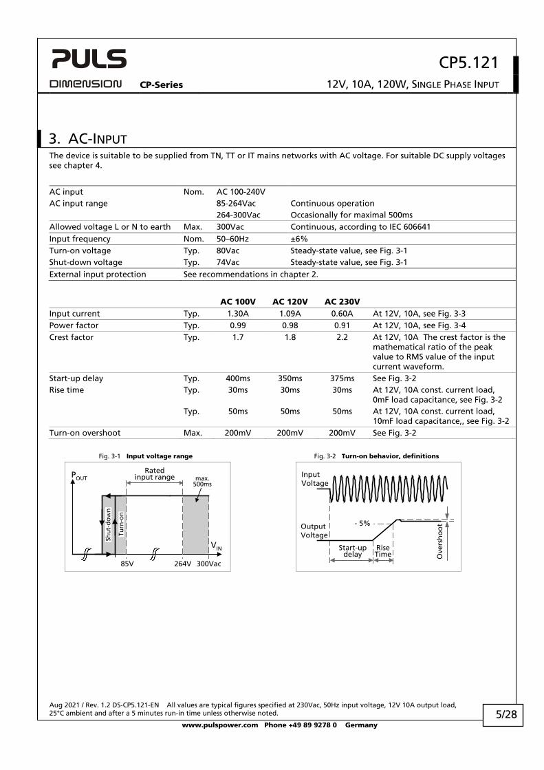
AC input Nom. AC 100-240V AC input range 85-264Vac Continuous operation 264-300Vac Occasionally for maximal 500ms Allowed voltage L or N to earth Max. 300Vac Continuous, according to IEC 606641 Input frequency Nom. 50–60Hz ±6% Turn-on voltage Typ. 80Vac Steady-state value, see Fig. 3-1 Shut-down voltage Typ. 74Vac Steady-state value, see Fig. 3-1 External input protection See recommendations in chapter 2.
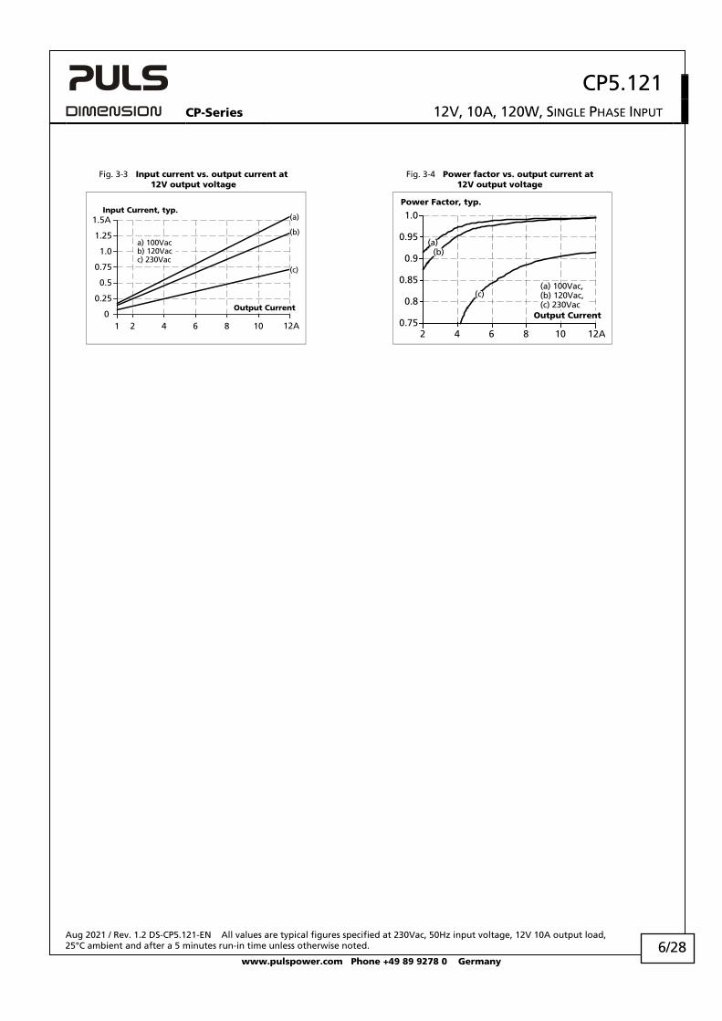
AC 100V AC 120V AC 230V Input current Typ. 1.30A 1.09A 0.60A At 12V, 10A, see Fig. 3-3 Power factor Typ. 0.99 0.98 0.91 At 12V, 10A, see Fig. 3-4 Crest factor Typ. 1.7 1.8 2.2 At 12V, 10A The crest factor is the
mathematical ratio of the peak value to RMS value of the input current waveform.
Start-up delay Typ. 400ms 350ms 375ms See Fig. 3-2 Rise time Typ. 30ms 30ms 30ms At 12V, 10A const. current load,
0mF load capacitance, see Fig. 3-2 Typ. 50ms 50ms 50ms At 12V, 10A const. current load,
10mF load capacitance,, see Fig. 3-2 Turn-on overshoot Max. 200mV 200mV 200mV See Fig. 3-2
Fig. 3-1 Input voltage range Fig. 3-2 Turn-on behavior, definitions
Turn
-on
85V
Ratedinput range max.
500ms
VIN
POUT
300Vac264V
Shu
t-d
ow
n
Start-updelay
RiseTime O
vers
ho
ot- 5%Output
Voltage
InputVoltage
CP5.121
CP-Series 12V, 10A, 120W, SINGLE PHASE INPUT
Aug 2021 / Rev. 1.2 DS-CP5.121-EN All values are typical figures specified at 230Vac, 50Hz input voltage, 12V 10A output load, 25°C ambient and after a 5 minutes run-in time unless otherwise noted.
www.pulspower.com Phone +49 89 9278 0 Germany 6/28
Fig. 3-3 Input current vs. output current at
12V output voltage Fig. 3-4 Power factor vs. output current at
12V output voltage
12A1 2 4 6 80
0.25
0.5
0.75
1.0
1.25
1.5AInput Current, typ.
10
a) 100Vacb) 120Vacc) 230Vac
Output Current
(a)
(b)
(c)
Power Factor, typ.
2 4 6 8 10 12A0.75
0.8
0.85
0.9
0.95
1.0
Output Current
(a) 100Vac,(b) 120Vac,(c) 230Vac
(a)(b)
(c)
CP5.121
CP-Series 12V, 10A, 120W, SINGLE PHASE INPUT
Aug 2021 / Rev. 1.2 DS-CP5.121-EN All values are typical figures specified at 230Vac, 50Hz input voltage, 12V 10A output load, 25°C ambient and after a 5 minutes run-in time unless otherwise noted.
www.pulspower.com Phone +49 89 9278 0 Germany 7/28
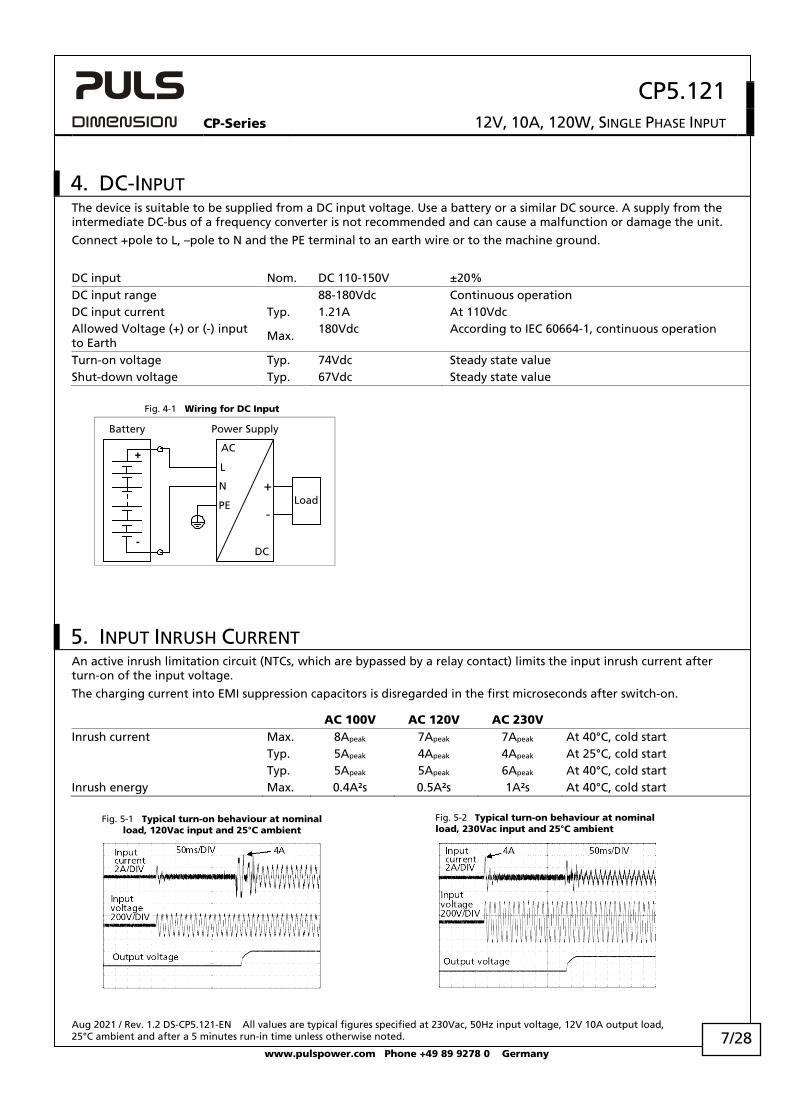
4. DC-INPUT The device is suitable to be supplied from a DC input voltage. Use a battery or a similar DC source. A supply from the intermediate DC-bus of a frequency converter is not recommended and can cause a malfunction or damage the unit.
Connect +pole to L, –pole to N and the PE terminal to an earth wire or to the machine ground.
DC input Nom. DC 110-150V ±20% DC input range 88-180Vdc Continuous operation DC input current Typ. 1.21A At 110Vdc Allowed Voltage (+) or (-) input to Earth
Max. 180Vdc According to IEC 60664-1, continuous operation
Turn-on voltage Typ. 74Vdc Steady state value Shut-down voltage Typ. 67Vdc Steady state value Fig. 4-1 Wiring for DC Input
+
-
Load
L
PE
+
-
Power Supply
AC
DC
Battery
N
5. INPUT INRUSH CURRENT An active inrush limitation circuit (NTCs, which are bypassed by a relay contact) limits the input inrush current after turn-on of the input voltage.
The charging current into EMI suppression capacitors is disregarded in the first microseconds after switch-on.
AC 100V AC 120V AC 230V Inrush current Max. 8Apeak 7Apeak 7Apeak At 40°C, cold start Typ. 5Apeak 4Apeak 4Apeak At 25°C, cold start Typ. 5Apeak 5Apeak 6Apeak At 40°C, cold start Inrush energy Max. 0.4A²s 0.5A²s 1A²s At 40°C, cold start Fig. 5-1 Typical turn-on behaviour at nominal
load, 120Vac input and 25°C ambient Fig. 5-2 Typical turn-on behaviour at nominal
load, 230Vac input and 25°C ambient
CP5.121
CP-Series 12V, 10A, 120W, SINGLE PHASE INPUT
Aug 2021 / Rev. 1.2 DS-CP5.121-EN All values are typical figures specified at 230Vac, 50Hz input voltage, 12V 10A output load, 25°C ambient and after a 5 minutes run-in time unless otherwise noted.
www.pulspower.com Phone +49 89 9278 0 Germany 8/28
6. OUTPUT The output provides a SELV/PELV rated voltage, which is galvanically isolated from the input voltage.
The device is designed to supply any kind of loads, including capacitive and inductive loads. If extreme large capacitors, such as EDLCs (electric double layer capacitors or “UltraCaps”) with a capacitance > 0.3F are connected to the output, the unit might charge the capacitor in an intermittent mode.
The output is electronically protected against overload, no-load and short-circuits. In case of a protection event, audible noise may occur.
Output voltage Nom. 12V Adjustment range 12-15V Guaranteed value Max. 16.0V This is the maximum output voltage which can
occur at the clockwise end position of the potentiometer due to tolerances. It is not a guaranteed value which can be achieved.
Factory settings Typ. 12.0V ±0.2%, at full load and cold unit Line regulation Max. 10mV Between 85 and 300Vac Load regulation Max. 50mV Between 0A and 12A, static value Ripple and noise voltage Max. 50mVpp Load >0.3A, Bandwidth 20Hz to 20MHz, 50Ohm Max. 200mVpp Load <0.3A, Bandwidth 20Hz to 20MHz, 50Ohm Output current Nom. 12A1) At 12V and an ambient temperatures below 45°C Nom. 10A At 12V and 60°C ambient temperature Nom. 7.5A At 12V and 70°C ambient temperature Nom. 9.6A1) At 15V and an ambient temperatures below 45°C Nom. 8.0A At 15V and 60°C ambient temperature Nom. 6.0A At 15V and 70°C ambient temperature Derate between +45°C and +70° Fuse breaking current Typ. 30A Up to 12ms once every five seconds, see Fig. 6-2.
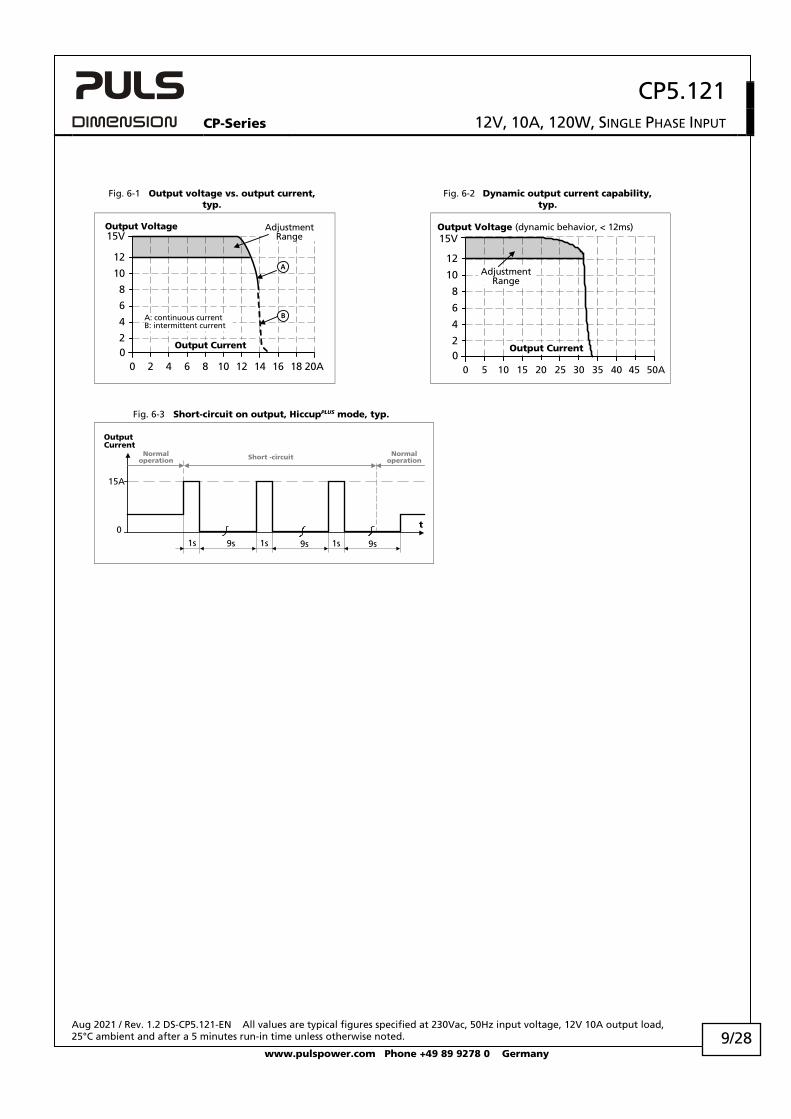
The fuse braking current is an enhanced transient current which helps to trip fuses on faulty output branches. The output voltage stays above 10V.
Overload behaviour Continuous current Output voltage > 8Vdc, see Fig. 6-1 Intermittent current2) Output voltage < 6Vdc, see Fig. 6-1 Overload/ short-circuit current Max. 14.2A Continuous current, see Fig. 6-1 Typ. 15A Intermitted current peak value for typ. 1s
Load impedance 50mOhm, see Fig. 6-3 Discharge current of output capacitors is not included.
Max. 5A Intermitted current average value (R.M.S.) Load impedance 50mOhm, see Fig. 6-3
Output capacitance Typ. 2 700µF Included inside the power supply Back-feeding loads Max. 25V The unit is resistant and does not show
malfunctioning when a load feeds back voltage to the power supply. It does not matter whether the power supply is on or off. The absorbing energy can be calculated according to the built-in large sized output capacitor.
1) This current is also available for temperatures up to +70°C with a duty cycle of 10% and/ or not longer than 1 minute every 10 minutes. 2) At heavy overloads (when output voltage falls below 7V), the power supply delivers continuous output current for 1s. After this, the output
is switched off for approx. 9s before a new start attempt is automatically performed. This cycle is repeated as long as the overload exists. If the overload has been cleared, the device will operate normally. See Fig. 6-3.
CP5.121
CP-Series 12V, 10A, 120W, SINGLE PHASE INPUT
Aug 2021 / Rev. 1.2 DS-CP5.121-EN All values are typical figures specified at 230Vac, 50Hz input voltage, 12V 10A output load, 25°C ambient and after a 5 minutes run-in time unless otherwise noted.
www.pulspower.com Phone +49 89 9278 0 Germany 9/28
Fig. 6-1 Output voltage vs. output current, typ.
Fig. 6-2 Dynamic output current capability, typ.
Output Voltage
00 12
2
4
6
15V
8
10
12
20A82 4 10 14 166 18
AdjustmentRange
Output Current
A: continuous currentB: intermittent current
A
B
Output Voltage (dynamic behavior, < 12ms)
00
2
4
6
15V
8
10
12
50A2010 30 405 15 25 35 45
AdjustmentRange
Output Current
Fig. 6-3 Short-circuit on output, HiccupPLUS mode, typ.
OutputCurrent
0
15A
9s 9s9s 1s 1s1s
t
Short -circuit Normaloperation
Normaloperation
CP5.121
CP-Series 12V, 10A, 120W, SINGLE PHASE INPUT
Aug 2021 / Rev. 1.2 DS-CP5.121-EN All values are typical figures specified at 230Vac, 50Hz input voltage, 12V 10A output load, 25°C ambient and after a 5 minutes run-in time unless otherwise noted.
www.pulspower.com Phone +49 89 9278 0 Germany 10/28
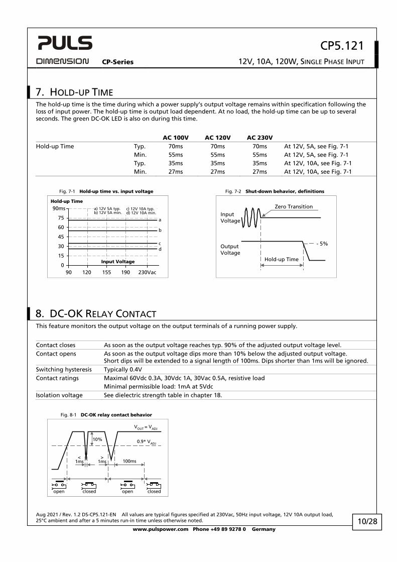
7. HOLD-UP TIME The hold-up time is the time during which a power supply’s output voltage remains within specification following the loss of input power. The hold-up time is output load dependent. At no load, the hold-up time can be up to several seconds. The green DC-OK LED is also on during this time.
AC 100V AC 120V AC 230V Hold-up Time Typ. 70ms 70ms 70ms At 12V, 5A, see Fig. 7-1 Min. 55ms 55ms 55ms At 12V, 5A, see Fig. 7-1 Typ. 35ms 35ms 35ms At 12V, 10A, see Fig. 7-1 Min. 27ms 27ms 27ms At 12V, 10A, see Fig. 7-1
Fig. 7-1 Hold-up time vs. input voltage Fig. 7-2 Shut-down behavior, definitions
0
15
30
45
60
90ms
90 120 155 190 230Vac
Input Voltage
75
Hold-up Time
a
b
cd
a) 12V 5A typ.b) 12V 5A min.
c) 12V 10A typ.d) 12V 10A min.
- 5%
Hold-up Time
Zero Transition
OutputVoltage
InputVoltage
8. DC-OK RELAY CONTACT This feature monitors the output voltage on the output terminals of a running power supply.
Contact closes As soon as the output voltage reaches typ. 90% of the adjusted output voltage level. Contact opens As soon as the output voltage dips more than 10% below the adjusted output voltage.
Short dips will be extended to a signal length of 100ms. Dips shorter than 1ms will be ignored. Switching hysteresis Typically 0.4V Contact ratings Maximal 60Vdc 0.3A, 30Vdc 1A, 30Vac 0.5A, resistive load Minimal permissible load: 1mA at 5Vdc Isolation voltage See dielectric strength table in chapter 18.
Fig. 8-1 DC-OK relay contact behavior
100ms
0.9* VADJ
<1ms
10%
open
VOUT = VADJ
openclosed closed
>1ms
CP5.121
CP-Series 12V, 10A, 120W, SINGLE PHASE INPUT
Aug 2021 / Rev. 1.2 DS-CP5.121-EN All values are typical figures specified at 230Vac, 50Hz input voltage, 12V 10A output load, 25°C ambient and after a 5 minutes run-in time unless otherwise noted.
www.pulspower.com Phone +49 89 9278 0 Germany 11/28
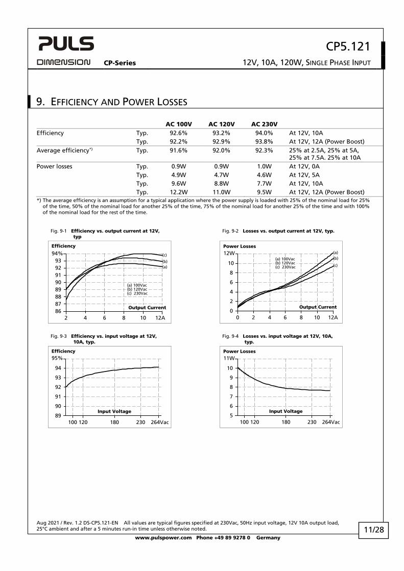
9. EFFICIENCY AND POWER LOSSES
AC 100V AC 120V AC 230V Efficiency Typ. 92.6% 93.2% 94.0% At 12V, 10A Typ. 92.2% 92.9% 93.8% At 12V, 12A (Power Boost) Average efficiency*) Typ. 91.6% 92.0% 92.3% 25% at 2.5A, 25% at 5A,
25% at 7.5A. 25% at 10A Power losses Typ. 0.9W 0.9W 1.0W At 12V, 0A Typ. 4.9W 4.7W 4.6W At 12V, 5A Typ. 9.6W 8.8W 7.7W At 12V, 10A Typ. 12.2W 11.0W 9.5W At 12V, 12A (Power Boost) *) The average efficiency is an assumption for a typical application where the power supply is loaded with 25% of the nominal load for 25%
of the time, 50% of the nominal load for another 25% of the time, 75% of the nominal load for another 25% of the time and with 100% of the nominal load for the rest of the time.
Fig. 9-1 Efficiency vs. output current at 12V, typ
Fig. 9-2 Losses vs. output current at 12V, typ.
Efficiency
2 4 6 10 12A
888990919293
94%
Output Current
8
(a)(b)
(c)
(a) 100Vac (b) 120Vac (c) 230Vac
8786
Power Losses
0 4 6 12A
2
0
4
6
8
12W
10
10
2 8
Output Current
(a)(b)
(c)
(a) 100Vac (b) 120Vac (c) 230Vac
Fig. 9-3 Efficiency vs. input voltage at 12V, 10A, typ.
Fig. 9-4 Losses vs. input voltage at 12V, 10A, typ.
Efficiency
120 180 230 264Vac89
90
91
92
Input Voltage
93
94
95%
100
Power Losses
120 180 230 264Vac5
6
7
8
Input Voltage
9
10
11W
100
CP5.121
CP-Series 12V, 10A, 120W, SINGLE PHASE INPUT
Aug 2021 / Rev. 1.2 DS-CP5.121-EN All values are typical figures specified at 230Vac, 50Hz input voltage, 12V 10A output load, 25°C ambient and after a 5 minutes run-in time unless otherwise noted.
www.pulspower.com Phone +49 89 9278 0 Germany 12/28
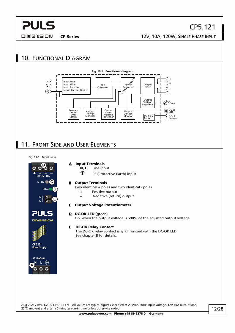
10. FUNCTIONAL DIAGRAM
Fig. 10-1 Functional diagram
++
--
OutputOver-
VoltageProtection
PFCConverter
OutputVoltage
Regulator
PowerConverter
OutputFilter
OutputVoltageMonitor
OutputPower
Manager
Temper-atureShut-down
Input FuseInput FilterInput RectifierInrush Current Limiter
VOUT
LN
DC-okContact
DC-okLED
DC-okRelay
11. FRONT SIDE AND USER ELEMENTS Fig. 11-1 Front side
A Input Terminals N, L Line input
PE (Protective Earth) input B Output Terminals
Two identical + poles and two identical - poles + Positive output
– Negative (return) output
C Output Voltage Potentiometer
D DC-OK LED (green) On, when the output voltage is >90% of the adjusted output voltage
E DC-OK Relay Contact The DC-OK relay contact is synchronized with the DC-OK LED. See chapter 8 for details.
CP5.121
CP-Series 12V, 10A, 120W, SINGLE PHASE INPUT
Aug 2021 / Rev. 1.2 DS-CP5.121-EN All values are typical figures specified at 230Vac, 50Hz input voltage, 12V 10A output load, 25°C ambient and after a 5 minutes run-in time unless otherwise noted.
www.pulspower.com Phone +49 89 9278 0 Germany 13/28
12. CONNECTION TERMINALS
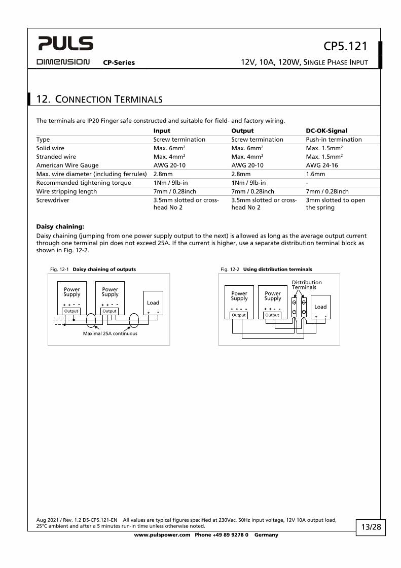
The terminals are IP20 Finger safe constructed and suitable for field- and factory wiring.
Input Output DC-OK-Signal Type Screw termination Screw termination Push-in termination Solid wire Max. 6mm2 Max. 6mm2 Max. 1.5mm2 Stranded wire Max. 4mm2 Max. 4mm2 Max. 1.5mm2 American Wire Gauge AWG 20-10 AWG 20-10 AWG 24-16 Max. wire diameter (including ferrules) 2.8mm 2.8mm 1.6mm Recommended tightening torque 1Nm / 9lb-in 1Nm / 9lb-in - Wire stripping length 7mm / 0.28inch 7mm / 0.28inch 7mm / 0.28inch Screwdriver 3.5mm slotted or cross-
head No 2 3.5mm slotted or cross-head No 2
3mm slotted to open the spring
Daisy chaining:
Daisy chaining (jumping from one power supply output to the next) is allowed as long as the average output current through one terminal pin does not exceed 25A. If the current is higher, use a separate distribution terminal block as shown in Fig. 12-2.
Fig. 12-1 Daisy chaining of outputs Fig. 12-2 Using distribution terminals
Load
+ -
PowerSupply
+ + - -Output
PowerSupply
+ + - -Output
Maximal 25A continuous
DistributionTerminals
Load
+ -
PowerSupply
+ + - -Output
PowerSupply
+ + - -Output
CP5.121
CP-Series 12V, 10A, 120W, SINGLE PHASE INPUT
Aug 2021 / Rev. 1.2 DS-CP5.121-EN All values are typical figures specified at 230Vac, 50Hz input voltage, 12V 10A output load, 25°C ambient and after a 5 minutes run-in time unless otherwise noted.
www.pulspower.com Phone +49 89 9278 0 Germany 14/28
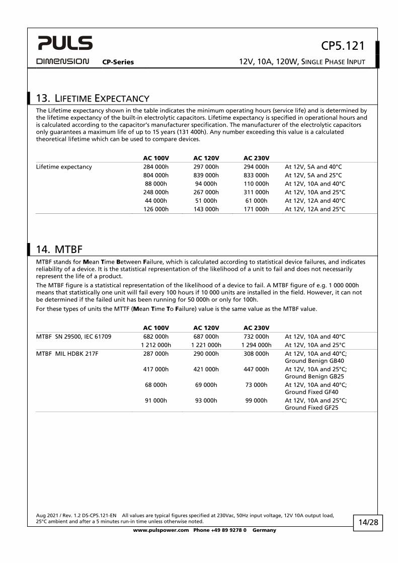
13. LIFETIME EXPECTANCY The Lifetime expectancy shown in the table indicates the minimum operating hours (service life) and is determined by the lifetime expectancy of the built-in electrolytic capacitors. Lifetime expectancy is specified in operational hours and is calculated according to the capacitor’s manufacturer specification. The manufacturer of the electrolytic capacitors only guarantees a maximum life of up to 15 years (131 400h). Any number exceeding this value is a calculated theoretical lifetime which can be used to compare devices.
AC 100V AC 120V AC 230V Lifetime expectancy 284 000h 297 000h 294 000h At 12V, 5A and 40°C 804 000h 839 000h 833 000h At 12V, 5A and 25°C 88 000h 94 000h 110 000h At 12V, 10A and 40°C 248 000h 267 000h 311 000h At 12V, 10A and 25°C 44 000h 51 000h 61 000h At 12V, 12A and 40°C 126 000h 143 000h 171 000h At 12V, 12A and 25°C
14. MTBF MTBF stands for Mean Time Between Failure, which is calculated according to statistical device failures, and indicates reliability of a device. It is the statistical representation of the likelihood of a unit to fail and does not necessarily represent the life of a product.
The MTBF figure is a statistical representation of the likelihood of a device to fail. A MTBF figure of e.g. 1 000 000h means that statistically one unit will fail every 100 hours if 10 000 units are installed in the field. However, it can not be determined if the failed unit has been running for 50 000h or only for 100h.
For these types of units the MTTF (Mean Time To Failure) value is the same value as the MTBF value.
AC 100V AC 120V AC 230V MTBF SN 29500, IEC 61709 682 000h 687 000h 732 000h At 12V, 10A and 40°C 1 212 000h 1 221 000h 1 294 000h At 12V, 10A and 25°C MTBF MIL HDBK 217F 287 000h 290 000h 308 000h At 12V, 10A and 40°C;
Ground Benign GB40 417 000h 421 000h 447 000h At 12V, 10A and 25°C;
Ground Benign GB25 68 000h 69 000h 73 000h At 12V, 10A and 40°C;
Ground Fixed GF40 91 000h 93 000h 99 000h At 12V, 10A and 25°C;
Ground Fixed GF25
CP5.121
CP-Series 12V, 10A, 120W, SINGLE PHASE INPUT
Aug 2021 / Rev. 1.2 DS-CP5.121-EN All values are typical figures specified at 230Vac, 50Hz input voltage, 12V 10A output load, 25°C ambient and after a 5 minutes run-in time unless otherwise noted.
www.pulspower.com Phone +49 89 9278 0 Germany 15/28
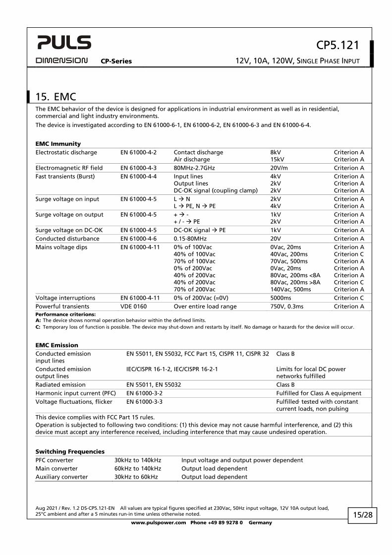
15. EMC The EMC behavior of the device is designed for applications in industrial environment as well as in residential, commercial and light industry environments.
The device is investigated according to EN 61000-6-1, EN 61000-6-2, EN 61000-6-3 and EN 61000-6-4.
EMC Immunity Electrostatic discharge EN 61000-4-2 Contact discharge
Air discharge 8kV 15kV
Criterion A Criterion A
Electromagnetic RF field EN 61000-4-3 80MHz-2.7GHz 20V/m Criterion A Fast transients (Burst) EN 61000-4-4 Input lines
Output lines DC-OK signal (coupling clamp)
4kV 2kV 2kV
Criterion A Criterion A Criterion A
Surge voltage on input EN 61000-4-5 L N L PE, N PE
2kV 4kV
Criterion A Criterion A
Surge voltage on output EN 61000-4-5 + - + / - PE
1kV 2kV
Criterion A Criterion A
Surge voltage on DC-OK EN 61000-4-5 DC-OK signal PE 1kV Criterion A Conducted disturbance EN 61000-4-6 0.15-80MHz 20V Criterion A Mains voltage dips EN 61000-4-11 0% of 100Vac
40% of 100Vac 70% of 100Vac 0% of 200Vac
40% of 200Vac 40% of 200Vac 70% of 200Vac
0Vac, 20ms 40Vac, 200ms 70Vac, 500ms 0Vac, 20ms 80Vac, 200ms <8A 80Vac, 200ms >8A 140Vac, 500ms
Criterion A Criterion C Criterion A Criterion A Criterion A Criterion C Criterion A
Voltage interruptions EN 61000-4-11 0% of 200Vac (=0V) 5000ms Criterion C Powerful transients VDE 0160 Over entire load range 750V, 0.3ms Criterion A Performance criterions: A: The device shows normal operation behavior within the defined limits. C: Temporary loss of function is possible. The device may shut-down and restarts by itself. No damage or hazards for the device will occur.
EMC Emission Conducted emission input lines
EN 55011, EN 55032, FCC Part 15, CISPR 11, CISPR 32 Class B
Conducted emission output lines
IEC/CISPR 16-1-2, IEC/CISPR 16-2-1 Limits for local DC power networks fulfilled
Radiated emission EN 55011, EN 55032 Class B Harmonic input current (PFC) EN 61000-3-2 Fulfilled for Class A equipment Voltage fluctuations, flicker EN 61000-3-3 Fulfilled, tested with constant
current loads, non pulsing This device complies with FCC Part 15 rules. Operation is subjected to following two conditions: (1) this device may not cause harmful interference, and (2) this device must accept any interference received, including interference that may cause undesired operation.
Switching Frequencies PFC converter 30kHz to 140kHz Input voltage and output power dependent Main converter 60kHz to 140kHz Output load dependent Auxiliary converter 30kHz to 60kHz Output load dependent
CP5.121
CP-Series 12V, 10A, 120W, SINGLE PHASE INPUT
Aug 2021 / Rev. 1.2 DS-CP5.121-EN All values are typical figures specified at 230Vac, 50Hz input voltage, 12V 10A output load, 25°C ambient and after a 5 minutes run-in time unless otherwise noted.
www.pulspower.com Phone +49 89 9278 0 Germany 16/28
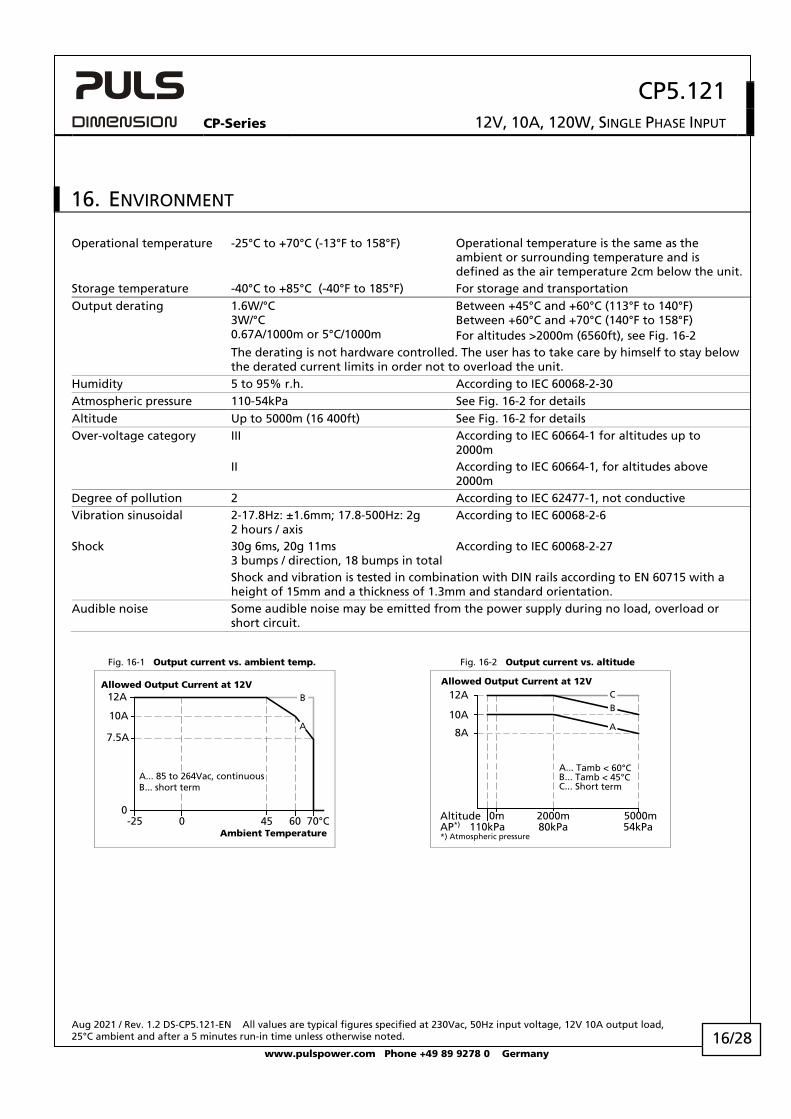
16. ENVIRONMENT
Operational temperature -25°C to +70°C (-13°F to 158°F) Operational temperature is the same as the ambient or surrounding temperature and is defined as the air temperature 2cm below the unit.
Storage temperature -40°C to +85°C (-40°F to 185°F) For storage and transportation Output derating 1.6W/°C
3W/°C 0.67A/1000m or 5°C/1000m
Between +45°C and +60°C (113°F to 140°F) Between +60°C and +70°C (140°F to 158°F) For altitudes >2000m (6560ft), see Fig. 16-2
The derating is not hardware controlled. The user has to take care by himself to stay below the derated current limits in order not to overload the unit.
Humidity 5 to 95% r.h. According to IEC 60068-2-30 Atmospheric pressure 110-54kPa See Fig. 16-2 for details Altitude Up to 5000m (16 400ft) See Fig. 16-2 for details Over-voltage category III According to IEC 60664-1 for altitudes up to
2000m II According to IEC 60664-1, for altitudes above
2000m Degree of pollution 2 According to IEC 62477-1, not conductive Vibration sinusoidal 2-17.8Hz: ±1.6mm; 17.8-500Hz: 2g
2 hours / axis According to IEC 60068-2-6
Shock 30g 6ms, 20g 11ms 3 bumps / direction, 18 bumps in total
According to IEC 60068-2-27
Shock and vibration is tested in combination with DIN rails according to EN 60715 with a height of 15mm and a thickness of 1.3mm and standard orientation.
Audible noise Some audible noise may be emitted from the power supply during no load, overload or short circuit.
Fig. 16-1 Output current vs. ambient temp. Fig. 16-2 Output current vs. altitude
Allowed Output Current at 12V
0-25 0 45 70°C
7.5A
10A
12A
60
A
Ambient Temperature
A... 85 to 264Vac, continuousB... short term
B
2000m 5000m
8A
10A
12A
Altitude
Allowed Output Current at 12V
B
A... Tamb < 60°CB... Tamb < 45°CC... Short term
A
C
AP*) 80kPa 54kPa110kPa0m
*) Atmospheric pressure
CP5.121
CP-Series 12V, 10A, 120W, SINGLE PHASE INPUT
Aug 2021 / Rev. 1.2 DS-CP5.121-EN All values are typical figures specified at 230Vac, 50Hz input voltage, 12V 10A output load, 25°C ambient and after a 5 minutes run-in time unless otherwise noted.
www.pulspower.com Phone +49 89 9278 0 Germany 17/28
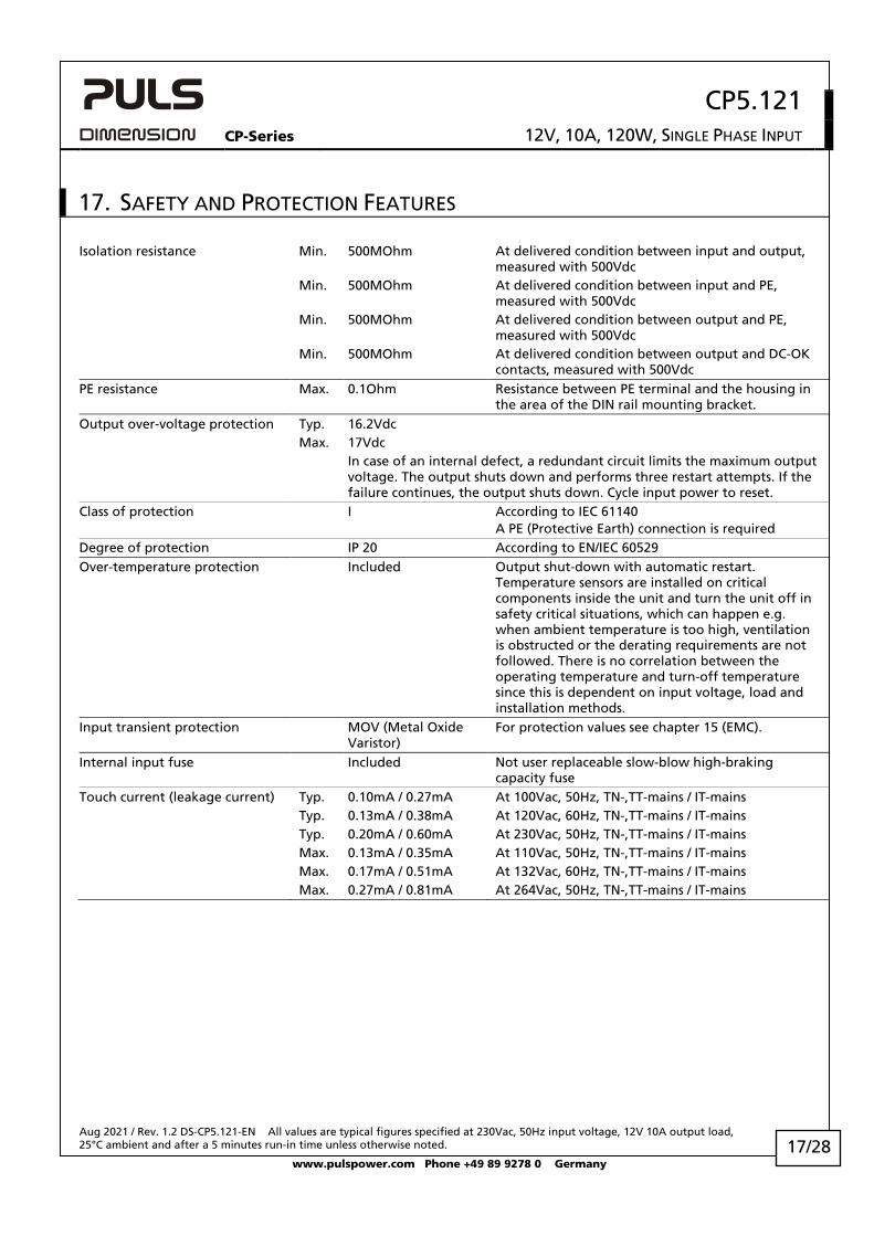
17. SAFETY AND PROTECTION FEATURES
Isolation resistance Min. 500MOhm At delivered condition between input and output, measured with 500Vdc
Min. 500MOhm At delivered condition between input and PE, measured with 500Vdc
Min. 500MOhm At delivered condition between output and PE, measured with 500Vdc
Min. 500MOhm At delivered condition between output and DC-OK contacts, measured with 500Vdc
PE resistance Max. 0.1Ohm Resistance between PE terminal and the housing in the area of the DIN rail mounting bracket.
Output over-voltage protection Typ. 16.2Vdc Max. 17Vdc In case of an internal defect, a redundant circuit limits the maximum output
voltage. The output shuts down and performs three restart attempts. If the failure continues, the output shuts down. Cycle input power to reset.
Class of protection I According to IEC 61140 A PE (Protective Earth) connection is required
Degree of protection IP 20 According to EN/IEC 60529 Over-temperature protection Included Output shut-down with automatic restart.
Temperature sensors are installed on critical components inside the unit and turn the unit off in safety critical situations, which can happen e.g. when ambient temperature is too high, ventilation is obstructed or the derating requirements are not followed. There is no correlation between the operating temperature and turn-off temperature since this is dependent on input voltage, load and installation methods.
Input transient protection MOV (Metal Oxide Varistor)
For protection values see chapter 15 (EMC).
Internal input fuse Included Not user replaceable slow-blow high-braking capacity fuse
Touch current (leakage current) Typ. 0.10mA / 0.27mA At 100Vac, 50Hz, TN-,TT-mains / IT-mains Typ. 0.13mA / 0.38mA At 120Vac, 60Hz, TN-,TT-mains / IT-mains Typ. 0.20mA / 0.60mA At 230Vac, 50Hz, TN-,TT-mains / IT-mains Max. 0.13mA / 0.35mA At 110Vac, 50Hz, TN-,TT-mains / IT-mains Max. 0.17mA / 0.51mA At 132Vac, 60Hz, TN-,TT-mains / IT-mains Max. 0.27mA / 0.81mA At 264Vac, 50Hz, TN-,TT-mains / IT-mains
CP5.121
CP-Series 12V, 10A, 120W, SINGLE PHASE INPUT
Aug 2021 / Rev. 1.2 DS-CP5.121-EN All values are typical figures specified at 230Vac, 50Hz input voltage, 12V 10A output load, 25°C ambient and after a 5 minutes run-in time unless otherwise noted.
www.pulspower.com Phone +49 89 9278 0 Germany 18/28
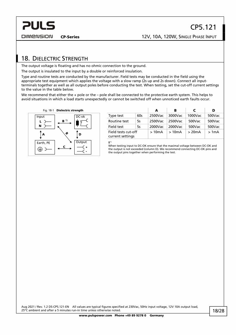
18. DIELECTRIC STRENGTH The output voltage is floating and has no ohmic connection to the ground.
The output is insulated to the input by a double or reinforced insulation.
Type and routine tests are conducted by the manufacturer. Field tests may be conducted in the field using the appropriate test equipment which applies the voltage with a slow ramp (2s up and 2s down). Connect all input-terminals together as well as all output poles before conducting the test. When testing, set the cut-off current settings to the value in the table below.
We recommend that either the + pole or the – pole shall be connected to the protective earth system. This helps to avoid situations in which a load starts unexpectedly or cannot be switched off when unnoticed earth faults occur.
Fig. 18-1 Dielectric strength A B C D
A D
C
B
B *)
NL
Input DC-ok
Earth, PE Output
-+
Type test 60s 2500Vac 3000Vac 1000Vac 500Vac
Routine test 5s 2500Vac 2500Vac 500Vac 500Vac
Field test 5s 2000Vac 2000Vac 500Vac 500Vac Field tests cut-off current settings
> 10mA > 10mA > 20mA > 1mA
B*) When testing input to DC-OK ensure that the maximal voltage between DC-OK and the output is not exceeded (column D). We recommend connecting DC-OK pins and the output pins together when performing the test.
CP5.121
CP-Series 12V, 10A, 120W, SINGLE PHASE INPUT
Aug 2021 / Rev. 1.2 DS-CP5.121-EN All values are typical figures specified at 230Vac, 50Hz input voltage, 12V 10A output load, 25°C ambient and after a 5 minutes run-in time unless otherwise noted.
www.pulspower.com Phone +49 89 9278 0 Germany 19/28
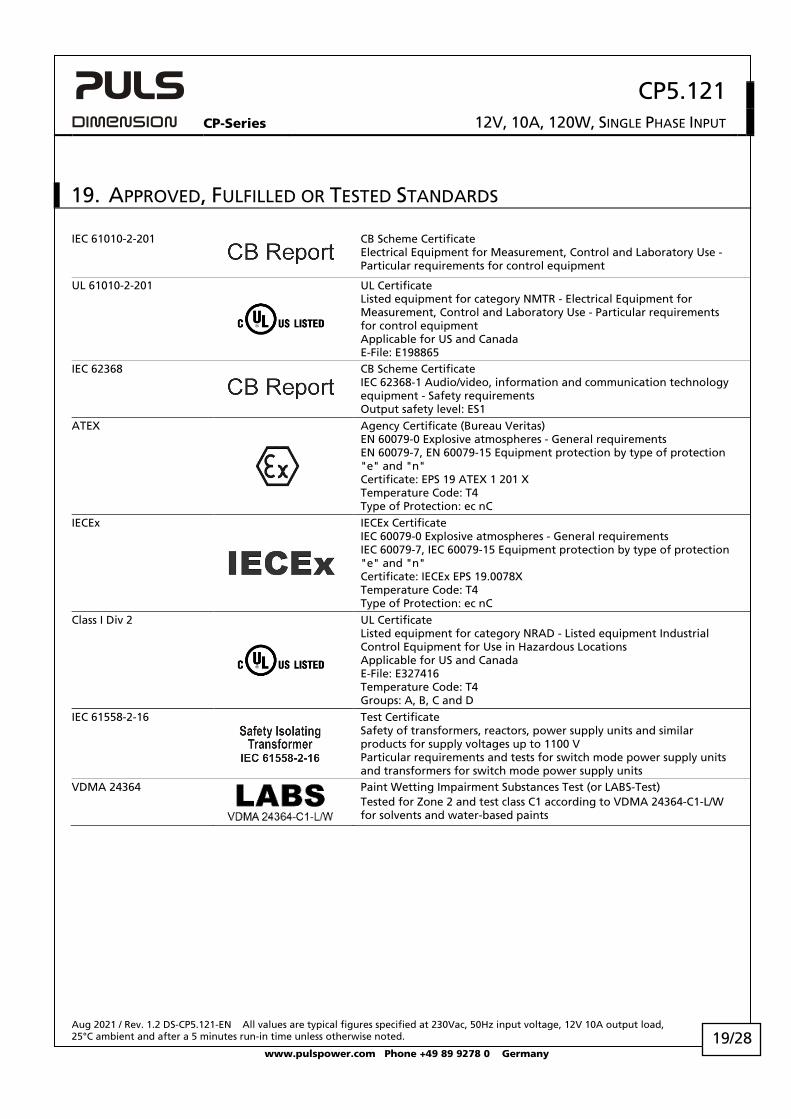
19. APPROVED, FULFILLED OR TESTED STANDARDS
IEC 61010-2-201
CB Scheme Certificate Electrical Equipment for Measurement, Control and Laboratory Use - Particular requirements for control equipment
UL 61010-2-201
UL Certificate Listed equipment for category NMTR - Electrical Equipment for Measurement, Control and Laboratory Use - Particular requirements for control equipment Applicable for US and Canada E-File: E198865
IEC 62368
CB Scheme Certificate IEC 62368-1 Audio/video, information and communication technology equipment - Safety requirements Output safety level: ES1
ATEX
Agency Certificate (Bureau Veritas) EN 60079-0 Explosive atmospheres - General requirements EN 60079-7, EN 60079-15 Equipment protection by type of protection "e" and "n" Certificate: EPS 19 ATEX 1 201 X Temperature Code: T4 Type of Protection: ec nC
IECEx
IECEx Certificate IEC 60079-0 Explosive atmospheres - General requirements IEC 60079-7, IEC 60079-15 Equipment protection by type of protection "e" and "n" Certificate: IECEx EPS 19.0078X Temperature Code: T4 Type of Protection: ec nC
Class I Div 2
UL Certificate Listed equipment for category NRAD - Listed equipment Industrial Control Equipment for Use in Hazardous Locations Applicable for US and Canada E-File: E327416 Temperature Code: T4 Groups: A, B, C and D
IEC 61558-2-16
Test Certificate Safety of transformers, reactors, power supply units and similar products for supply voltages up to 1100 V Particular requirements and tests for switch mode power supply units and transformers for switch mode power supply units
VDMA 24364
Paint Wetting Impairment Substances Test (or LABS-Test) Tested for Zone 2 and test class C1 according to VDMA 24364-C1-L/W for solvents and water-based paints
CP5.121
CP-Series 12V, 10A, 120W, SINGLE PHASE INPUT
Aug 2021 / Rev. 1.2 DS-CP5.121-EN All values are typical figures specified at 230Vac, 50Hz input voltage, 12V 10A output load, 25°C ambient and after a 5 minutes run-in time unless otherwise noted.
www.pulspower.com Phone +49 89 9278 0 Germany 20/28
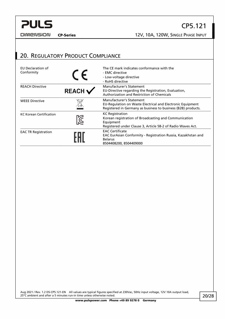
20. REGULATORY PRODUCT COMPLIANCE
EU Declaration of Conformity
The CE mark indicates conformance with the - EMC directive - Low-voltage directive - RoHS directive
REACH Directive
Manufacturer's Statement EU-Directive regarding the Registration, Evaluation, Authorization and Restriction of Chemicals
WEEE Directive
Manufacturer's Statement EU-Regulation on Waste Electrical and Electronic Equipment Registered in Germany as business to business (B2B) products.
KC Korean Certification
KC Registration Korean registration of Broadcasting and Communication Equipment Registered under Clause 3, Article 58-2 of Radio Waves Act.
EAC TR Registration
EAC Certificate EAC EurAsian Conformity - Registration Russia, Kazakhstan and Belarus 8504408200, 8504409000
CP5.121
CP-Series 12V, 10A, 120W, SINGLE PHASE INPUT
Aug 2021 / Rev. 1.2 DS-CP5.121-EN All values are typical figures specified at 230Vac, 50Hz input voltage, 12V 10A output load, 25°C ambient and after a 5 minutes run-in time unless otherwise noted.
www.pulspower.com Phone +49 89 9278 0 Germany 21/28
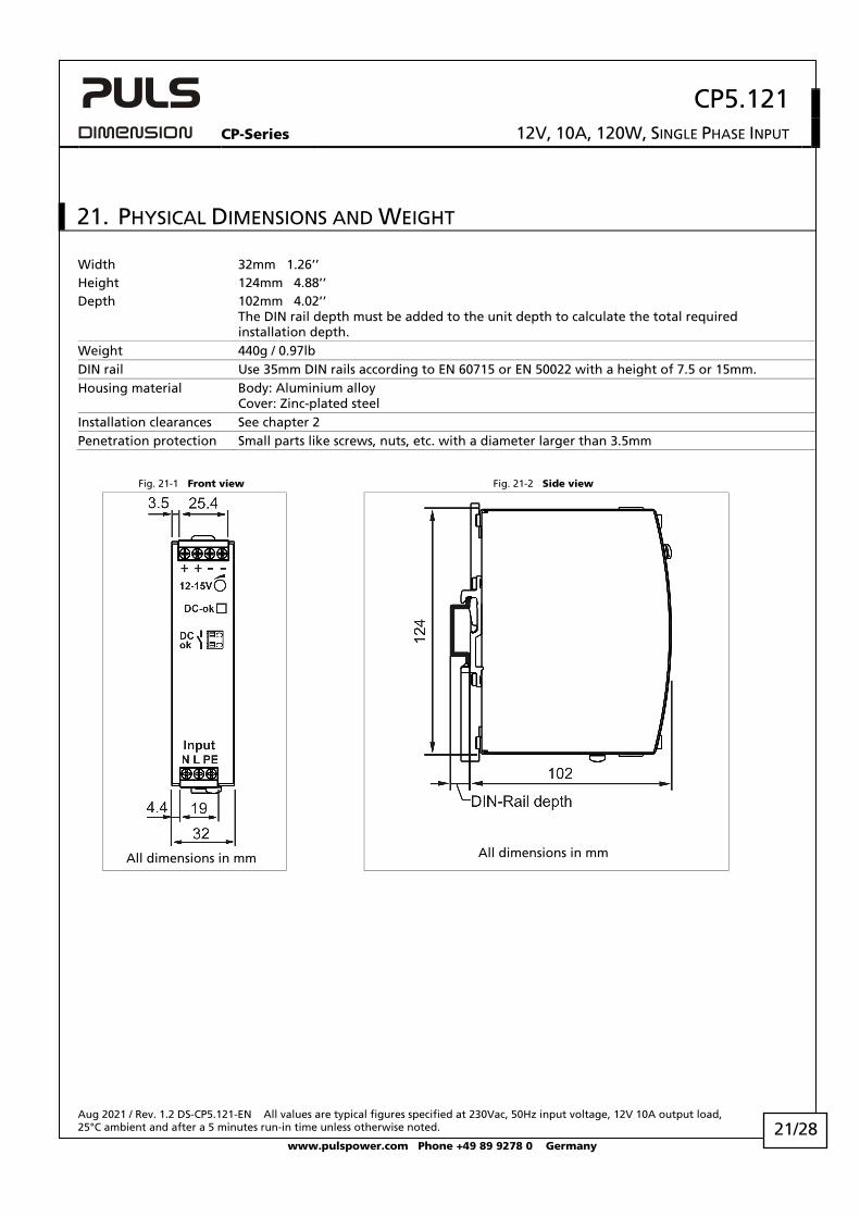
21. PHYSICAL DIMENSIONS AND WEIGHT
Width 32mm 1.26’’ Height 124mm 4.88’’ Depth 102mm 4.02’’
The DIN rail depth must be added to the unit depth to calculate the total required installation depth.
Weight 440g / 0.97lb DIN rail Use 35mm DIN rails according to EN 60715 or EN 50022 with a height of 7.5 or 15mm. Housing material Body: Aluminium alloy
Cover: Zinc-plated steel Installation clearances See chapter 2 Penetration protection Small parts like screws, nuts, etc. with a diameter larger than 3.5mm
Fig. 21-1 Front view Fig. 21-2 Side view
All dimensions in mm
All dimensions in mm
CP5.121
CP-Series 12V, 10A, 120W, SINGLE PHASE INPUT
Aug 2021 / Rev. 1.2 DS-CP5.121-EN All values are typical figures specified at 230Vac, 50Hz input voltage, 12V 10A output load, 25°C ambient and after a 5 minutes run-in time unless otherwise noted.
www.pulspower.com Phone +49 89 9278 0 Germany 22/28
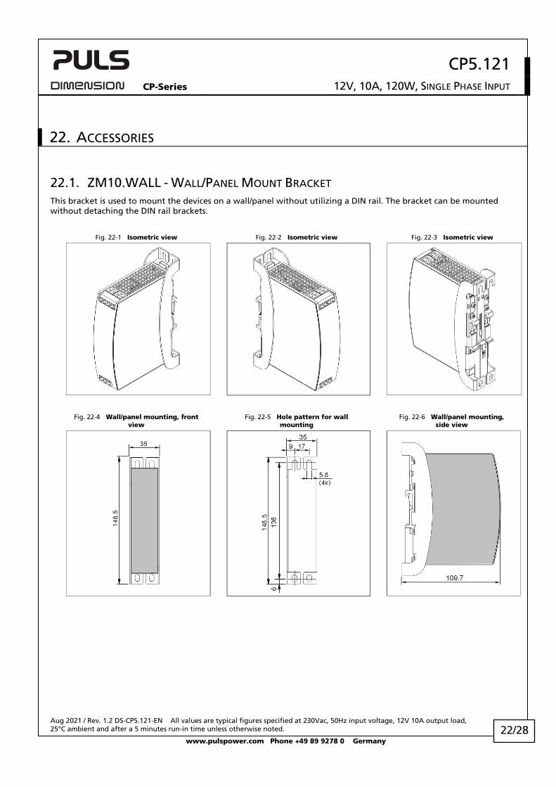
22. ACCESSORIES
22.1. ZM10.WALL - WALL/PANEL MOUNT BRACKET This bracket is used to mount the devices on a wall/panel without utilizing a DIN rail. The bracket can be mounted without detaching the DIN rail brackets.
Fig. 22-1 Isometric view Fig. 22-2 Isometric view Fig. 22-3 Isometric view
Fig. 22-4 Wall/panel mounting, front view
Fig. 22-5 Hole pattern for wall mounting
Fig. 22-6 Wall/panel mounting, side view
CP5.121
CP-Series 12V, 10A, 120W, SINGLE PHASE INPUT
Aug 2021 / Rev. 1.2 DS-CP5.121-EN All values are typical figures specified at 230Vac, 50Hz input voltage, 12V 10A output load, 25°C ambient and after a 5 minutes run-in time unless otherwise noted.
www.pulspower.com Phone +49 89 9278 0 Germany 23/28
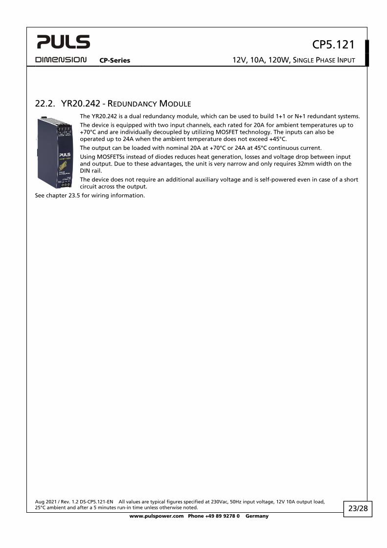
22.2. YR20.242 - REDUNDANCY MODULE The YR20.242 is a dual redundancy module, which can be used to build 1+1 or N+1 redundant systems.
The device is equipped with two input channels, each rated for 20A for ambient temperatures up to +70°C and are individually decoupled by utilizing MOSFET technology. The inputs can also be operated up to 24A when the ambient temperature does not exceed +45°C.
The output can be loaded with nominal 20A at +70°C or 24A at 45°C continuous current.
Using MOSFETSs instead of diodes reduces heat generation, losses and voltage drop between input and output. Due to these advantages, the unit is very narrow and only requires 32mm width on the DIN rail.
The device does not require an additional auxiliary voltage and is self-powered even in case of a short circuit across the output.
See chapter 23.5 for wiring information.
CP5.121
CP-Series 12V, 10A, 120W, SINGLE PHASE INPUT
Aug 2021 / Rev. 1.2 DS-CP5.121-EN All values are typical figures specified at 230Vac, 50Hz input voltage, 12V 10A output load, 25°C ambient and after a 5 minutes run-in time unless otherwise noted.
www.pulspower.com Phone +49 89 9278 0 Germany 24/28
23. APPLICATION NOTES
23.1. PEAK CURRENT CAPABILITY The unit can deliver peak currents (up to several milliseconds) which are higher than the specified short term currents.
This helps to start current demanding loads. Solenoids, contactors and pneumatic modules often have a steady state coil and a pick-up coil. The inrush current demand of the pick-up coil is several times higher than the steady-state current and usually exceeds the nominal output current. The same situation applies when starting a capacitive load.
The peak current capability also ensures the safe operation of subsequent circuit breakers of load circuits. The load branches are often individually protected with circuit breakers or fuses. In case of a short or an overload in one branch circuit, the fuse or circuit breaker need a certain amount of over-current to open in a timely manner. This avoids voltage loss in adjacent circuits.
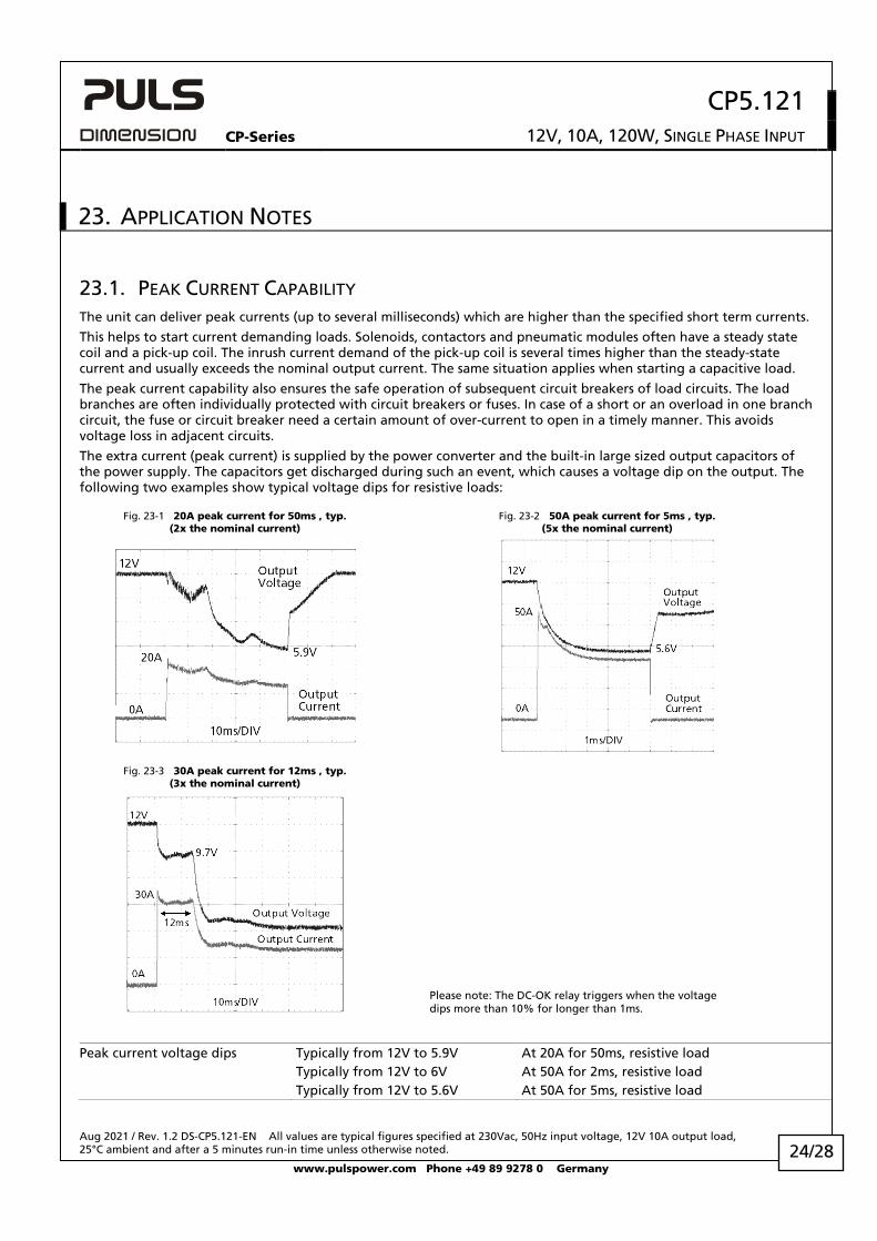
The extra current (peak current) is supplied by the power converter and the built-in large sized output capacitors of the power supply. The capacitors get discharged during such an event, which causes a voltage dip on the output. The following two examples show typical voltage dips for resistive loads:
Fig. 23-1 20A peak current for 50ms , typ. (2x the nominal current)
Fig. 23-2 50A peak current for 5ms , typ. (5x the nominal current)
Fig. 23-3 30A peak current for 12ms , typ. (3x the nominal current)
Please note: The DC-OK relay triggers when the voltage dips more than 10% for longer than 1ms.
Peak current voltage dips Typically from 12V to 5.9V At 20A for 50ms, resistive load Typically from 12V to 6V At 50A for 2ms, resistive load Typically from 12V to 5.6V At 50A for 5ms, resistive load
CP5.121
CP-Series 12V, 10A, 120W, SINGLE PHASE INPUT
Aug 2021 / Rev. 1.2 DS-CP5.121-EN All values are typical figures specified at 230Vac, 50Hz input voltage, 12V 10A output load, 25°C ambient and after a 5 minutes run-in time unless otherwise noted.
www.pulspower.com Phone +49 89 9278 0 Germany 25/28
23.2. CHARGING OF BATTERIES The power supply can be used to charge lead-acid or maintenance free VRLA batteries.
Instructions for charging batteries:
a) Ensure that the ambient temperature of the power supply stays below 40°C.
b) Use a 15A or 16A circuit breaker or a blocking diode between the power supply and the battery.
c) Ensure that the output current of the power supply is below the allowed charging current of the battery.
d) The return current to the power supply is typically 8mA. This return current can discharge the battery when the power supply is switched off except in case a blocking diode is utilized.
e) Set the output voltage, measured at no load and at the battery end of the cable, very precisely to the end-of-charge voltage. Set the output voltage, measured at no load and at the battery end of the cable, very precisely to the end-of-charge voltage. The voltage should be set to 13.9V at 10°C, 13.75V at 20°C, 13.6V at 30°C and 13.4V at 40°C ambient temperature.
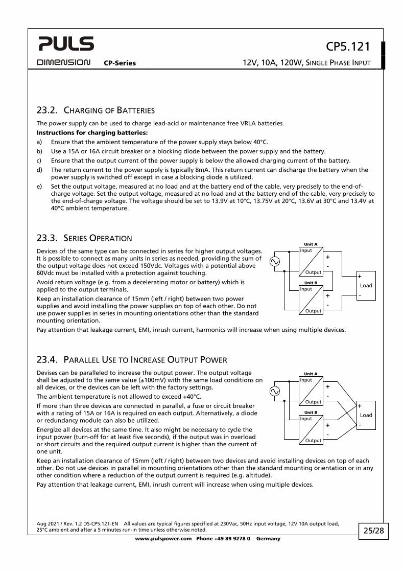
23.3. SERIES OPERATION Devices of the same type can be connected in series for higher output voltages. It is possible to connect as many units in series as needed, providing the sum of the output voltage does not exceed 150Vdc. Voltages with a potential above 60Vdc must be installed with a protection against touching.
Avoid return voltage (e.g. from a decelerating motor or battery) which is applied to the output terminals.
Keep an installation clearance of 15mm (left / right) between two power supplies and avoid installing the power supplies on top of each other. Do not use power supplies in series in mounting orientations other than the standard mounting orientation.
Pay attention that leakage current, EMI, inrush current, harmonics will increase when using multiple devices.
23.4. PARALLEL USE TO INCREASE OUTPUT POWER Devises can be paralleled to increase the output power. The output voltage shall be adjusted to the same value (±100mV) with the same load conditions on all devices, or the devices can be left with the factory settings.
The ambient temperature is not allowed to exceed +40°C.
If more than three devices are connected in parallel, a fuse or circuit breaker with a rating of 15A or 16A is required on each output. Alternatively, a diode or redundancy module can also be utilized.
Energize all devices at the same time. It also might be necessary to cycle the input power (turn-off for at least five seconds), if the output was in overload or short circuits and the required output current is higher than the current of one unit.
Keep an installation clearance of 15mm (left / right) between two devices and avoid installing devices on top of each other. Do not use devices in parallel in mounting orientations other than the standard mounting orientation or in any other condition where a reduction of the output current is required (e.g. altitude).
Pay attention that leakage current, EMI, inrush current will increase when using multiple devices.
Unit A
Unit B
-
+-
+
Load
+
-
Input
Output
Input
Output
Unit A
Input
Output
Unit B
-
+-
+
Load
+
-Input
Output
CP5.121
CP-Series 12V, 10A, 120W, SINGLE PHASE INPUT
Aug 2021 / Rev. 1.2 DS-CP5.121-EN All values are typical figures specified at 230Vac, 50Hz input voltage, 12V 10A output load, 25°C ambient and after a 5 minutes run-in time unless otherwise noted.
www.pulspower.com Phone +49 89 9278 0 Germany 26/28
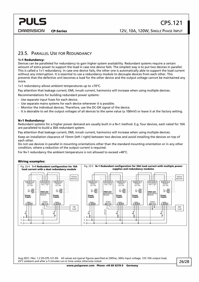
23.5. PARALLEL USE FOR REDUNDANCY 1+1 Redundancy: Devices can be paralleled for redundancy to gain higher system availability. Redundant systems require a certain amount of extra power to support the load in case one device fails. The simplest way is to put two devices in parallel. This is called a 1+1 redundancy. In case one device fails, the other one is automatically able to support the load current without any interruption. It is essential to use a redundancy module to decouple devices from each other. This prevents that the defective unit becomes a load for the other device and the output voltage cannot be maintained any more.
1+1 redundancy allows ambient temperatures up to +70°C.
Pay attention that leakage current, EMI, inrush current, harmonics will increase when using multiple devices.
Recommendations for building redundant power systems:
- Use separate input fuses for each device. - Use separate mains systems for each device whenever it is possible. - Monitor the individual devices. Therefore, use the DC-OK signal of the device. - It is desirable to set the output voltages of all devices to the same value (± 100mV) or leave it at the factory setting.
N+1 Redundancy: Redundant systems for a higher power demand are usually built in a N+1 method. E.g. four devices, each rated for 10A are paralleled to build a 30A redundant system.
Pay attention that leakage current, EMI, inrush current, harmonics will increase when using multiple devices.
Keep an installation clearance of 15mm (left / right) between two devices and avoid installing the devices on top of each other. Do not use devices in parallel in mounting orientations other than the standard mounting orientation or in any other condition, where a reduction of the output current is required.
For N+1 redundancy the ambient temperature is not allowed to exceed +40°C.
Wiring examples:
Fig. 23-4 1+1 Redundant configuration for 10A load current with a dual redundancy module
Fig. 23-5 N+1 Redundant configuration for 30A load current with multiple power supplies and redundancy modules
L
N
PE
10ALoad
FailureMonitor
I
YR20.242RedundancyModule
Output
Input 1
Input2
+ +- -
+-
op
tio
nal
PowerSupply
12V, 10A
DC-OK
+ + - -
L N PE
Output
Input
oo
PowerSupply
12V, 10A
DC-OK
+ + - -
L N PE
Output
Input
oo
I
L
N
PE
30ALoad
FailureMonitor
I
YR20.242RedundancyModule
Output
Input 1
Input2
+ +- -
+-
op
tio
nal
PowerSupply
12V, 10A
DC-OK
+ + - -
L N PE
Output
Input
oo
PowerSupply
12V, 10A
DC-OK
+ + - -
L N PE
Output
Input
oo
I
YR20.242RedundancyModule
Output
Input 1
Input2
+ +- -
+-
PowerSupply
12V, 10A
DC-OK
+ + - -
L N PE
Output
Input
oo
PowerSupply
12V, 10A
DC-OK
+ + - -
L N PE
Output
Input
oo
I I
CP5.121
CP-Series 12V, 10A, 120W, SINGLE PHASE INPUT
Aug 2021 / Rev. 1.2 DS-CP5.121-EN All values are typical figures specified at 230Vac, 50Hz input voltage, 12V 10A output load, 25°C ambient and after a 5 minutes run-in time unless otherwise noted.
www.pulspower.com Phone +49 89 9278 0 Germany 27/28
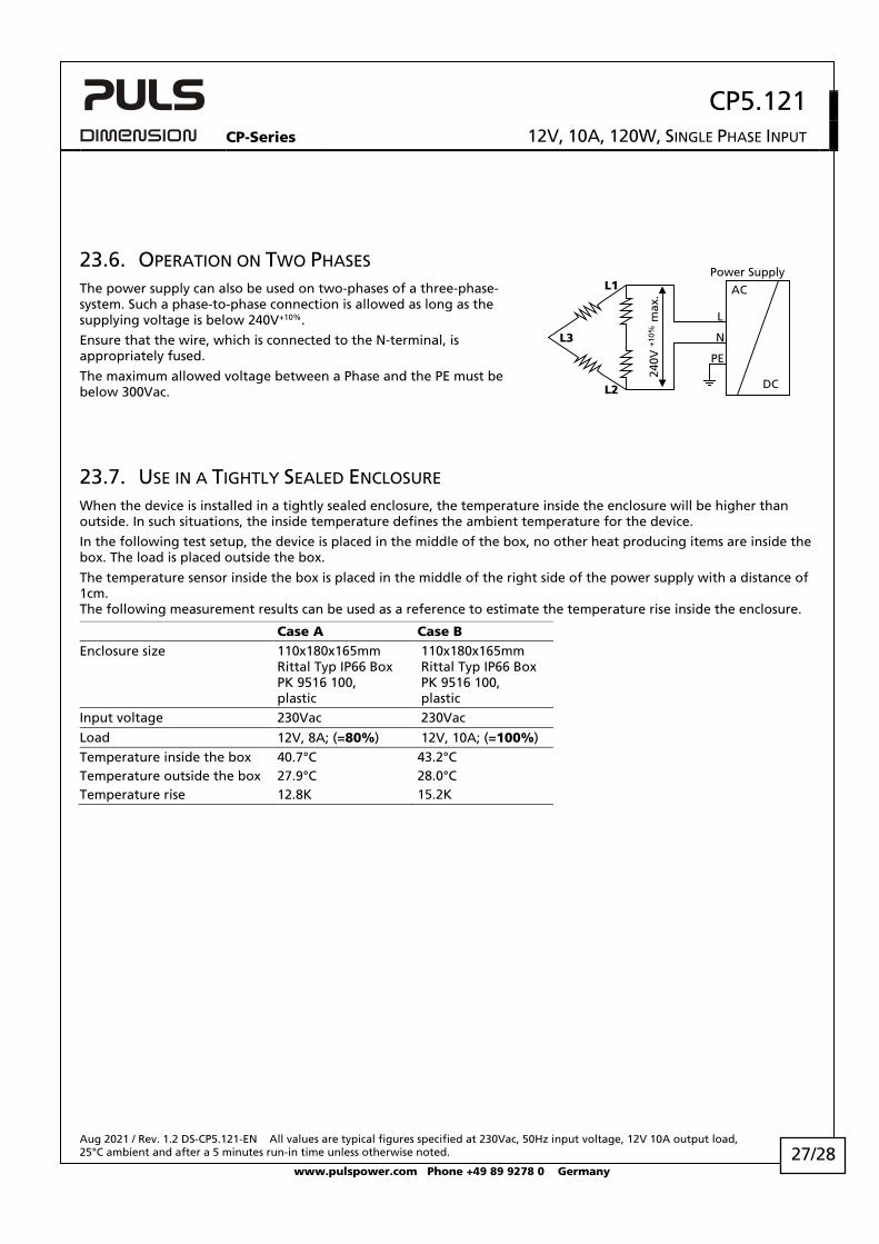
23.6. OPERATION ON TWO PHASES The power supply can also be used on two-phases of a three-phase-system. Such a phase-to-phase connection is allowed as long as the supplying voltage is below 240V+10%.
Ensure that the wire, which is connected to the N-terminal, is appropriately fused.
The maximum allowed voltage between a Phase and the PE must be below 300Vac.
23.7. USE IN A TIGHTLY SEALED ENCLOSURE When the device is installed in a tightly sealed enclosure, the temperature inside the enclosure will be higher than outside. In such situations, the inside temperature defines the ambient temperature for the device.
In the following test setup, the device is placed in the middle of the box, no other heat producing items are inside the box. The load is placed outside the box.
The temperature sensor inside the box is placed in the middle of the right side of the power supply with a distance of 1cm. The following measurement results can be used as a reference to estimate the temperature rise inside the enclosure.
Case A Case B Enclosure size 110x180x165mm
Rittal Typ IP66 Box PK 9516 100, plastic
110x180x165mm Rittal Typ IP66 Box PK 9516 100, plastic
Input voltage 230Vac 230Vac Load 12V, 8A; (=80%) 12V, 10A; (=100%) Temperature inside the box 40.7°C 43.2°C Temperature outside the box 27.9°C 28.0°C Temperature rise 12.8K 15.2K
240V
+10
% m
ax.
L2
L1
L3
L
N
PE
Power Supply
AC
DC
CP5.121
CP-Series 12V, 10A, 120W, SINGLE PHASE INPUT
Aug 2021 / Rev. 1.2 DS-CP5.121-EN All values are typical figures specified at 230Vac, 50Hz input voltage, 12V 10A output load, 25°C ambient and after a 5 minutes run-in time unless otherwise noted.
www.pulspower.com Phone +49 89 9278 0 Germany 28/28
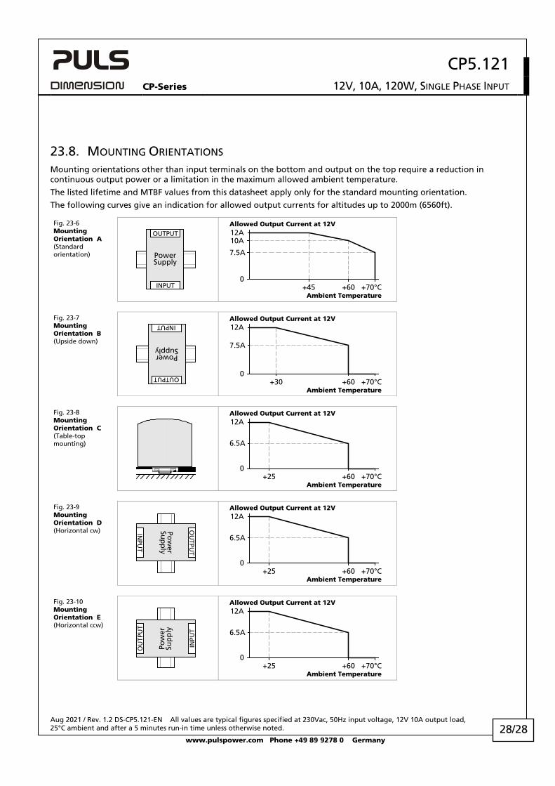
23.8. MOUNTING ORIENTATIONS Mounting orientations other than input terminals on the bottom and output on the top require a reduction in continuous output power or a limitation in the maximum allowed ambient temperature.
The listed lifetime and MTBF values from this datasheet apply only for the standard mounting orientation.
The following curves give an indication for allowed output currents for altitudes up to 2000m (6560ft).
Fig. 23-6 Mounting Orientation A (Standard orientation) Power
Supply
OUTPUT
INPUT
Allowed Output Current at 12V
0+45 +70°C
7.5A
10A12A
Ambient Temperature+60
Fig. 23-7 Mounting Orientation B (Upside down)
PowerSupply
OUTPUT
INPUT
Allowed Output Current at 12V
0+30 +70°C
7.5A
12A
Ambient Temperature+60
Fig. 23-8 Mounting Orientation C (Table-top mounting)
Allowed Output Current at 12V
0+25 +70°C
6.5A
12A
Ambient Temperature+60
Fig. 23-9 Mounting Orientation D (Horizontal cw) Po
wer
Sup
ply
OU
TPUT
INPU
T
Allowed Output Current at 12V
0+25 +70°C
6.5A
12A
Ambient Temperature+60
Fig. 23-10 Mounting Orientation E (Horizontal ccw)
Pow
erSu
pp
ly
OU
TPU
T
INPU
T
Allowed Output Current at 12V
0+25 +70°C
6.5A
12A
Ambient Temperature+60