cover photo of desert bighorn ewe and lamb at the butte ... · cover photo of desert bighorn ewe...
TRANSCRIPT


Cover photo of Desert Bighorn ewe and lamb at the Butte Guzzler eastof Mina, Nevada, by Andy Stinson of Hawthorne, Nevada.
Chapter Two and Appendix A photos by William R. “Rick” Brigham,BLM Carson City District, Nevada.
COPIES AVAILABLE FROM:
BLM National Business CenterPrinted Materials Distribution Service, BC-652
P.O. Box 25047Denver, Colorado 80225-0047
303-236-7637
TN 397BLM/RS/ST-96/009+6500/REV03
This document is also available on the NSTC website at http://www.blm.gov/nstc
Production services provided by:
Publishing StaffPeter Doran (303-236-6547)
Janine Koselak: Layout and DesignKathy Rohling: Editing
Lee Barkow, DirectorNational Science & Technology CenterP.O. Box 25047Denver, Colorado 80225-0047
The Bureau of Land Management’s National Scienceand Technology Center supports other BLM offices byproviding a broad spectrum of services in areas such asphysical, biological, and social science assessments; architecture and engineering support; library assistance;mapping science; photo imaging; geographic informationsystems applications; and publications support.

By:
William R. “Rick” BrighamBureau of Land Management
Carson City, Nevada
Craig StevensonNevada Division of Wildlife
Las Vegas, Nevada

Suggested citation:
Brigham, W.R. and C. Stevenson. 1997, Revised 2003. Wildlife Water Catchment Construction inNevada. Technical Note 397. Bureau of Land Management, Denver, Colorado. BLM/RS/ST-96/0091-6500/REV03. 97 pp.

WI
LD
LI
FE
W
AT
ER
C
AT
CH
ME
NT
C
ON
ST
RU
CT
IO
N
IN
N
EV
AD
A
i
AbstractThis technical note describes twoartificial water catchment (guzzler)construction methods that are used innorthern and southern Nevada. Innorthern Nevada, a standard guzzlerunit is constructed, and a site is locatedin which to install it. In southernNevada, the slickrock and artificialapron units are tailored to specificsites. Each of these methods includesdetailed information on site selection,
site preparation, selection and trans-port of materials and equipment, andstep-by-step construction information.The technical note should giveprospective builders enough informationto construct a guzzler on their own.The note also includes informationon construction methods and materialsthat have proven to be less than suc-cessful, and a brief section on otherwater development methods.


WI
LD
LI
FE
W
AT
ER
C
AT
CH
ME
NT
C
ON
ST
RU
CT
IO
N
IN
N
EV
AD
A
iii
AcknowledgmentsSeptember 1997VersionThe authors wish to thank the manyinterested and energetic volunteergroups for providing most of the laborand much of the funding for the watercatchment projects and for the manyideas they have contributed—theyhave greatly enhanced the quality ofthe projects.
Both authors are indebted to LarryJohnson of the Reno Chapter ofNevada Bighorns Unlimited (NBU).Larry has been the prime mover incoordinating volunteers and funding.
Author Rick Brigham works closelywith three local groups: the Reno andFallon Chapters of NBU and theHawthorne Sportsmen. A note ofthanks to Ralph McClintock, whointroduced Rick to the NBU organiza-tion back in 1987. This is when thebig game guzzler program in theCarson City District really got off theground. These partnerships evolved tothe point that the two NBU groupsfunded and built most of the big gameguzzlers in BLM’s Carson CityDistrict. Without their support, theCarson City District would not havethe water developments that now exist.
Author Craig Stevenson works closelywith the Fraternity of the DesertBighorn at Las Vegas, Nevada, andreceives much of the funding for hisprogram from the Reno Chapter ofNBU.
We would be remiss if we failed tomention Ed Pribyl with the Fraternityof the Desert Bighorn and Royce“Woody” Wood, formerly with theFraternity, and now a director for theFoundation for North American WildSheep. Ed has been the quiet strengthof the Fraternity and Woody greatlyimproved the Fraternity’s fundraisingcapabilities, placing helicopter use inour grasp so that we might place watercatchments further from harm andmore accessible to wildlife.
Thanks to Ray Boyd, now retired, forcoordinating the production processfor the original version of this technicalnote.
September 2003Revision UpdateThanks to Clint Bentley and his partner,Cindy Alexander, recent mainstays inthe Fraternity of the Desert Bighorn.Clint has added his considerable con-tracting and construction knowledgeand skills to the Fraternity’s ongoingwater development efforts.
Thanks also to Kathy Rohling,writer/editor, and Janine Koselak,Visual Information Specialist, both of BLM’s National Science andTechnology Center in Denver for theediting, layout, and final productionof this revised publication.


WI
LD
LI
FE
W
AT
ER
C
AT
CH
ME
NT
C
ON
ST
RU
CT
IO
N
IN
N
EV
AD
A
v
A Note About the AuthorsRick Brigham has been a BLMwildlife biologist for 35 years. He hasserved in three districts in two statesand has been building guzzlers since1974.
Craig Stevenson is a wildlife biologistwith the Nevada Division of Wildlifein Las Vegas, Nevada. He has beenwith the Division for 21 years and isthe “water-development-for-wildlifeexpert” in southern Nevada.


WI
LD
LI
FE
W
AT
ER
C
AT
CH
ME
NT
C
ON
ST
RU
CT
IO
N
IN
N
EV
AD
A
vii
Table of ContentsAbstract . . . . . . . . . . . . . . . . . . . . . . . . . . . . . . . . . . . . . . . . . . . . . . . . . . . . .iAcknowledgments . . . . . . . . . . . . . . . . . . . . . . . . . . . . . . . . . . . . . . . . . . . . .iiiA Note About the Authors . . . . . . . . . . . . . . . . . . . . . . . . . . . . . . . . . . . . . . .vChapter 1 - Introduction . . . . . . . . . . . . . . . . . . . . . . . . . . . . . . . . . . . . . . . .1Chapter 2 - Northern Nevada Water Catchment Guidelines . . . . . . . . . . . . . . .3
Small and Big Game Guzzlers . . . . . . . . . . . . . . . . . . . . . . . . . . . . . . . . . .3Site Selection . . . . . . . . . . . . . . . . . . . . . . . . . . . . . . . . . . . . . . . . . . . . . .5
Small Game Guzzler . . . . . . . . . . . . . . . . . . . . . . . . . . . . . . . . . . . . . .5Big Game Guzzler . . . . . . . . . . . . . . . . . . . . . . . . . . . . . . . . . . . . . . .5
Site Preparation . . . . . . . . . . . . . . . . . . . . . . . . . . . . . . . . . . . . . . . . . . . .6Small Game Guzzler . . . . . . . . . . . . . . . . . . . . . . . . . . . . . . . . . . . . . .6Big Game Guzzler . . . . . . . . . . . . . . . . . . . . . . . . . . . . . . . . . . . . . . .6
Materials and Equipment Transport . . . . . . . . . . . . . . . . . . . . . . . . . . . . . .6Construction . . . . . . . . . . . . . . . . . . . . . . . . . . . . . . . . . . . . . . . . . . . . . .7
Plumbing the Tanks . . . . . . . . . . . . . . . . . . . . . . . . . . . . . . . . . . . . . .7Setting the Tanks . . . . . . . . . . . . . . . . . . . . . . . . . . . . . . . . . . . . . . .10Plumbing and Setting the Drinker . . . . . . . . . . . . . . . . . . . . . . . . . . .13Apron Construction . . . . . . . . . . . . . . . . . . . . . . . . . . . . . . . . . . . . .15
Beams and Uprights . . . . . . . . . . . . . . . . . . . . . . . . . . . . . . . . . .15Sheeting . . . . . . . . . . . . . . . . . . . . . . . . . . . . . . . . . . . . . . . . . . .20
Gutter Construction . . . . . . . . . . . . . . . . . . . . . . . . . . . . . . . . . . . . .21Fences . . . . . . . . . . . . . . . . . . . . . . . . . . . . . . . . . . . . . . . . . . . . . . .26
Buck and Rail Fence . . . . . . . . . . . . . . . . . . . . . . . . . . . . . . . . . .26Smooth Wire/4-5 Stand Barbed Wire Fence . . . . . . . . . . . . . . . . .26Small Game Guzzler Fence . . . . . . . . . . . . . . . . . . . . . . . . . . . . .26
Loose Ends . . . . . . . . . . . . . . . . . . . . . . . . . . . . . . . . . . . . . . . . . . . . . . .29Comments on Substitutions . . . . . . . . . . . . . . . . . . . . . . . . . . . . . . . . . .29
Table 1 – Materials/Parts List for Small Game Guzzler . . . . . . . . . . . .30Table 2 – Materials/Parts List for Big Game Guzzler . . . . . . . . . . . . . .31Table 3 – Equipment/Tools Checklist for Guzzler and Fence
Construction . . . . . . . . . . . . . . . . . . . . . . . . . . . . . . . . . . 35Table 4 – Big Game Guzzler General Checklist . . . . . . . . . . . . . . . . .38Specification drawing 1 – Water Storage Tank–Small Game Guzzler . .40Specification drawing 2 – Tank and Cover Corner Details . . . . . . . . .41Specification drawing 3 – Tank Cover Details . . . . . . . . . . . . . . . . . .42Specification drawing 4 – Ramp Details . . . . . . . . . . . . . . . . . . . . . . .43Specification drawing 5 – Water Storage Tank–Big Game Guzzler . . . .44Specification drawing 6 – Walk-Down Drinker . . . . . . . . . . . . . . . . .45

WI
LD
LI
FE
W
AT
ER
C
AT
CH
ME
NT
C
ON
ST
RU
CT
IO
N
IN
N
EV
AD
A
viii
Table of Contents (cont)Chapter 3 - Southern Nevada Water Catchment Guidelines . . . . . . . . . . . . . .47
Slickrock and Hypalon Guzzlers . . . . . . . . . . . . . . . . . . . . . . . . . . . . . . .47Site Selection . . . . . . . . . . . . . . . . . . . . . . . . . . . . . . . . . . . . . . . . . . . . .47Collection Surfaces . . . . . . . . . . . . . . . . . . . . . . . . . . . . . . . . . . . . . . . . .48
Slickrock . . . . . . . . . . . . . . . . . . . . . . . . . . . . . . . . . . . . . . . . . . . . .48Tarp Aprons . . . . . . . . . . . . . . . . . . . . . . . . . . . . . . . . . . . . . . . . . . .50
Construction . . . . . . . . . . . . . . . . . . . . . . . . . . . . . . . . . . . . . . . . . . . . .51General Comments . . . . . . . . . . . . . . . . . . . . . . . . . . . . . . . . . . . . . .51Slickrock Dam Construction . . . . . . . . . . . . . . . . . . . . . . . . . . . . . . .51Hypalon Apron Construction . . . . . . . . . . . . . . . . . . . . . . . . . . . . . .54General Plumbing . . . . . . . . . . . . . . . . . . . . . . . . . . . . . . . . . . . . . . .57Pipeline . . . . . . . . . . . . . . . . . . . . . . . . . . . . . . . . . . . . . . . . . . . . . .61Tank Location . . . . . . . . . . . . . . . . . . . . . . . . . . . . . . . . . . . . . . . . .61Tank Pad . . . . . . . . . . . . . . . . . . . . . . . . . . . . . . . . . . . . . . . . . . . . .62Tanks . . . . . . . . . . . . . . . . . . . . . . . . . . . . . . . . . . . . . . . . . . . . . . . .63Polytank Setup . . . . . . . . . . . . . . . . . . . . . . . . . . . . . . . . . . . . . . . . .67Pipeline Inflow . . . . . . . . . . . . . . . . . . . . . . . . . . . . . . . . . . . . . . . . .67Equalizers . . . . . . . . . . . . . . . . . . . . . . . . . . . . . . . . . . . . . . . . . . . . .69Overflows . . . . . . . . . . . . . . . . . . . . . . . . . . . . . . . . . . . . . . . . . . . . .69Manifold - Tanks to Drinker . . . . . . . . . . . . . . . . . . . . . . . . . . . . . . .72Insulation . . . . . . . . . . . . . . . . . . . . . . . . . . . . . . . . . . . . . . . . . . . . .72Float Box . . . . . . . . . . . . . . . . . . . . . . . . . . . . . . . . . . . . . . . . . . . . .72Drinker . . . . . . . . . . . . . . . . . . . . . . . . . . . . . . . . . . . . . . . . . . . . . .76Fences . . . . . . . . . . . . . . . . . . . . . . . . . . . . . . . . . . . . . . . . . . . . . . .76
Table 1 – Sources for Water Development Materials . . . . . . . . . . . . . . . . .79Table 2 – Polyethylene Tank Sizes . . . . . . . . . . . . . . . . . . . . . . . . . . . . . .80
Chapter 4 - Aerial Transportation of Materials and Equipment . . . . . . . . . . . .81Helicopter Transport . . . . . . . . . . . . . . . . . . . . . . . . . . . . . . . . . . . . . . . .81
Safety . . . . . . . . . . . . . . . . . . . . . . . . . . . . . . . . . . . . . . . . . . . . . . . .81Paperwork/Forms . . . . . . . . . . . . . . . . . . . . . . . . . . . . . . . . . . . . . . .82Load Preparation . . . . . . . . . . . . . . . . . . . . . . . . . . . . . . . . . . . . . . .82Staging . . . . . . . . . . . . . . . . . . . . . . . . . . . . . . . . . . . . . . . . . . . . . . .85External Load Equipment/Sling Operations . . . . . . . . . . . . . . . . . . . .86
Appendix A - Additional Water Catchment Devices . . . . . . . . . . . . . . . . . . . .89Appendix B - Lasting Waters for Bighorn by Robert S. Gray . . . . . . . . . . . . . . .95

WI
LD
LI
FE
W
AT
ER
C
AT
CH
ME
NT
C
ON
ST
RU
CT
IO
N
IN
N
EV
AD
A
1
Chapter 1-IntroductionNevada is the driest state in the UnitedStates. Usable water for humans, live-stock, mining, or fish and wildlife is ata premium. Rainfall is as low as 4 inchesper year in many areas and surfacewater is often nonexistent.
Water is one of the four essential habi-tat components for vertebrate wildlifespecies; the other three are food, coverand space. Where water is lacking, butother habitat essentials are available tobenefit wildlife, water may be developedusing artificial means, or a combinationof artificial and natural means.
The purpose of this technical note isto describe artificial water catchmentconstruction methods that are used inNevada, including site selection, sitepreparation, and transport of materialsand equipment. This technical note isnot meant to be all inclusive, butshould give the prospective “guzzler”builder enough information to getstarted. The technical note alsoincludes information on constructionmethods and materials that haveproven less than successful.
Nevada began a wildlife water develop-ment program in the 1950s. Big gamewater catchments were a novelty in theearly years. The emphasis, initially, wason water catchments for small gamebird species. One of the first bighorn(Ovis canadensis spp.) water catchmentswas constructed in June 1956 and wasonly recently “rediscovered” in southernNevada.
Although there was a push for bighornwater catchments in the 1970s, it wasn’t
until the early to mid-1980s that aprogram concentrating on bighornsheep habitat evaluation and improve-ment was developed. The goal of theprogram was to establish viable bighornpopulations in historic and otherwisesuitable habitats throughout Nevada.More often, the program focused onmitigating the loss of natural watersources. The projects that were con-structed to improve bighorn habitatultimately proved more useful to allwildlife species than did the earliersmall game units.
A term used for artificial water catch-ments for terrestrial wildlife species is“guzzler.” The term was originallycoined in 1943 as “gallinaceous guzzler”by Ben Glading, who at the time washead of the California Department ofFish and Game (CDFG). Many partsof California lacked surface water forsmall game species, and the CDFGmade a major effort over the nextseveral decades to develop water forgallinaceous birds, especially CaliforniaQuail (Lophortyx californicus), mourningdoves (Zenaidura macroura), and theintroduced chukar partridge (Alectorischukar).
A guzzler consists of an apron for col-lecting precipitation, a tank to store itin, and access to the water by differentsized wildlife species.
Materials used in guzzler constructionhave varied considerably in the past 40years. In northern Nevada, where mostsoils and surface rock are comparativelyporous, steel is preferred for theaprons. Fiberglass and cross-linked

WI
LD
LI
FE
W
AT
ER
C
AT
CH
ME
NT
C
ON
ST
RU
CT
IO
N
IN
N
EV
AD
A
2
polyethylene are preferred for thestorage tanks, PVC or plastic for theplumbing fittings, polypipe for thehose, and brass for the gate and floatvalves.
In southern Nevada, where soils andsurface rock may be as impervious andconcrete, natural aprons are usedwherever possible. These are called“slickrock” aprons and they utilizenatural features such as small gullies.Where slickrock is not available,hypalon fabric may be used.Polyethylene is used for the storagetanks, polypipe for the hose, steel forthe pipe fittings, and brass for the valves.
A main consideration in building theguzzlers, whether in the northern ofsouthern parts of Nevada, is to buildthem as simple and as strong as possi-ble. This results in fewer problems andreduced maintenance costs.
Guzzlers are constructed in two basicsizes. The small guzzler attracts smallgame and nongame species such asquail, doves, chukars, rabbits (Sylvilagusspp.), and neotropical (migrating)birds. The large guzzler accommodatesgame such as antelope (Antilocapraamericana), big horn sheep, and muledeer (Odocoileus hemionus).
In the information that follows,Chapter 2, Northern Nevada WaterCatchments Guidelines, explains howwater catchments are built by theBureau of Land Management in north-ern Nevada, specifically by the CarsonCity District. This set of guidelines hasbeen fine tuned over the past 14 years.Chapter 3, Southern Nevada WaterCatchment Guidelines, contains infor-
mation on slickrock collection surfacesfeeding storage tanks and drinkers.The information, originally publishedin an abbreviated form in 1988, hasbeen updated to reflect the experienceand expertise that has accrued sincethen. This chapter also contains infor-mation on artificial (hypalon) apronsplaced at ground level.
In Chapters 2 and 3, the authors eachdescribe a different constructionmethod. In Chapter 2, author RickBrigham constructs a fixed guzzler unitand then finds the appropriate settingin which to install it. In Chapter 3,author Craig Stevenson employs aflexible unit (in terms of materials)and tailors each unit to it’s selectedsite. Both approaches have been veryeffective.
Chapter 4, Aerial Transportation ofMaterials and Equipment, is based onthe collective experience of bothauthors in the use of helicopters totransport materials and equipment toremote sites.
Appendix A, Additional WaterCatchment Devices, discusses other typesof natural and artificial water-catchingand storing devices.
Appendix B, Lasting Waters for Bighorn,was originally presented to the 1974Desert Bighorn Council by its lateauthor, Robert S. Gray, who was presi-dent of the Arizona Desert BighornSheep Society (ADBSS) at the time.Gray’s paper is reprinted here in itsentirety with the permission of theADBSS. It contains useful informationon sealing rock for either collection orstorage of water.

WI
LD
LI
FE
W
AT
ER
C
AT
CH
ME
NT
C
ON
ST
RU
CT
IO
N
IN
N
EV
AD
A
3
Chapter 2-NorthernNevada WaterCatchment GuidelinesSmall and BigGame GuzzlersThe BLM’s Carson City District innorthern Nevada currently has 126BLM guzzlers, plus 102 more thatwere constructed by other agencies onthe 5 million acres of public lands inthe district. The guzzler designs used atCarson City have evolved over the last27 years. The guzzlers are designed andbuilt to last at least 30 years and to bevirtually maintenance free. No slick-rock catchments have been constructedsince opportunities for this design arevery limited in this region. (SeeChapter 3 for slick rock developmentsin southern Nevada)
A small game guzzler consists of asingle 5-foot x 10-foot x 30-inchfiberglass storage tank of 800 galloncapacity, with a bolt-on lid that is openat one end, and a walk-down ramp tothe water, overlain by a 16-foot x 16-foot almost horizontal steel roofingcollection apron supported by aframework of steel “C” beams on steeluprights. Small game guzzlers havebeen constructed primarily for chukarand mourning dove. Two people candig the hole for the tank and build theunit in two days or less if the hole isdug with a backhoe.
A big game guzzler consists of five ofthe same fiberglass storage tanks asthose used for the small game guzzlers(or two of the Boss polypropylenetanks) set side by side in the ground,plumbed together underground, andoverlain by four to six of the samecollecting aprons used on small gameguzzlers. The four to six aprons mayalso be combined into two side by sideaprons. The roofs of the tanks, however,are solid; they are not open at one end.
The tanks are connected by under-ground plumbing to a separate, uncov-ered walk-down/ramped fiberglassdrinker that is 36 inches x 72 inches x30 inches deep. The water level in thedrinker is controlled either by a floatvalve or by a self-leveling system.
The unit is protected by a fence vary-ing in length from between 250 to 1,200 feet, comprised of either woodposts/buck and rail, or 4-5 strandbarbed wire and smooth wire on steelposts and corners.
The big game guzzlers in the CarsonCity District have been constructedprimarily for desert bighorn sheep, andsecondarily for mule deer and antelope.
Small and big game guzzlers are pro-duced in four phases: site selection; sitepreparation; materials and equipmenttransport; and construction.
Specification DrawingsSee specification drawingsat the end of this chapter forthe small game guzzler,specifically the water stor-age tank, roof ramp, andtank and cover corner detail.Also see Table 1 (end ofchapter) for the small gameguzzler materials/parts list.
See specification drawingsat the end of this chapterfor the big game guzzler,including the drinker, andfor the small game roof,which is the same as thebig fame roof except bothends are closed. Also seePhotos 1 and 2. See Table 2for the big game guzzlermaterials/ parts list.

WI
LD
LI
FE
W
AT
ER
C
AT
CH
ME
NT
C
ON
ST
RU
CT
IO
N
IN
N
EV
AD
A
4
Photo 1. Northern guzzler details. Front aprons share three central uprights; rear apron sharesuprights with one front apron. Gutter is in place and connected to tanks. Tops of tanks andsewer and drainpipe (S&D) protecting gate valves are visible.
Photo 2. Brass float valve, arm and ball, with fittings. Two steel floor flanges are needed perassembly. All components are 1 1/2-inch in diameter. All flange bolts, nuts, and washers arestainless steel.

WI
LD
LI
FE
W
AT
ER
C
AT
CH
ME
NT
C
ON
ST
RU
CT
IO
N
IN
N
EV
AD
A
5
Site Selection
Small Game GuzzlerThe site for the small game guzzlershould be located where the speciesusing it would normally expect to findwater. It should be located in adequatehabitat, such as canyons or draws inhilly areas with adequate escape cover(shrubs or rocks) close by for chukars,and the same or flat areas for mourningdoves.
Many of the current small game guz-zlers are located in wash bottoms, buton small benches so they won’t washaway during thunderstorms. The inter-sections where several small canyonscome together are also very good forchukars.
The site should:• be as flat as possible for ease of
construction.• contain soft soil for ease in digging.• be located away from outcrops and
outcrop areas• avoid depressions. If the tank is
nearly empty and a thunderstorm orflood hits, it may float the tank outbefore it has a chance to fill.
Situate the tank opening so the sundoesn’t shine into it and so that it facesaway from the prevailing wind; bothcut down on evaporation. If possible,have it face north. Keep in mind, how-ever, that the tank opening will attractmore birds, especially flying mourningdoves, if it faces the wash, and if theapron is high enough above it thatdoves flying in the wash/canyon willsee the water in the tank.
Helpful HintRead these instructions all the way through tofamiliarize yourself withthe overall process beforestarting your guzzler. Somesteps of the constructionprocess are performed con-currently, which can savetime and money.
Another good location for small gameguzzlers is in areas where small gamepredators are found. These animalshunt in good small game habitats.
Big Game GuzzlerThe site for the big game guzzlershould be located where the speciesusing it would normally expect to findwater. It should be located in adequatehabitat (except for water) for the primary species, which is usually incanyon bottoms/washes for desertbighorns and mule deer, and openflat/gently rolling areas for antelope.Make sure the catchment sits up out ofthe wash on a small bench so it willnot be destroyed by high water duringthunderstorms.
The site should:• be as flat as possible for ease of
construction.• contain soft soil for ease in digging.• avoid depressions. If the tanks are
nearly empty and a thunderstorm orflood hits, it may float the tanks outbefore they have a chance to fill.
Leave room around the guzzler for afence if livestock of feral horses orburros are in the area and constitute athreat to the water source. The fencesare usually 240 to 300 feet in circum-ference for deer and bighorn, and aminimum of 300 feet in length oneach of four sides for antelope. Whilethe 300 x 300 foot fence has been usedfor antelope, they will also use thewaters protected by the smaller, shorterfences, including buck and rail.

WI
LD
LI
FE
W
AT
ER
C
AT
CH
ME
NT
C
ON
ST
RU
CT
IO
N
IN
N
EV
AD
A
6
Site Preparation
Small Game GuzzlerFor a small game guzzler, mark off thearea for the tank. The hole size is 6 feetx 11 feet x 30 inches. It can be dug byhand, backhoe, or Bobcat. The bottomof the hole should be level so the tankis level. Use a 36-inch or longer levelto ensure that the tank sets level in thehole. Backfill around the tank usingfine material; large or sharp rocks willpoke holes in the tank when theweight of the water pushes down. Thetank should sit in the ground so thatthe entrance used by the birds is aninch or two above the surroundingdirt. Pave the area in front of theopening with flat rocks, if possible, tokeep dirt from blowing into the tank.When finished, proceed to the ApronConstruction section in this chapter.
Big Game GuzzlerFor a big game guzzler, mark off thearea for the tanks. The hole size is12-feet x 28-feet x 30-inches deep forfive fiberglass tanks, or 18-feet x 19-feet x 24-inches for Boss tanks. It can be dug by hand, backhoe, orBobcat; it can also be blasted. Blastingloosens the soil so the hole can becleaned out easily. The big gameguzzler tank holes in the Carson CityDistrict were blasted using commer-cially prepared Anfo (ammoniumnitrate and fuel oil). It comes in verysmall pellet form in 50 pound bags(costs about $10 a bag) or in 5-inch x30-inch sausages. It usually requiresthree to four bags or sausages per site,depending upon rockiness.
The Carson City District uses a quali-fied blaster. The blasting crew consists
of approximately 4 to 10 agency people,including Explosive Ordnance Disposal(EOD) personnel from the local navalaircraft base. More personnel may beneeded if blasting materials and diggingequipment must be carried to the site.For safety reasons, the holes are blastedup to a month before constructiontakes place and before materials aredelivered to the site.
Materials andEquipmentTransportMaterials and equipment can be trans-ported to the site either by truck orhelicopter. The fiberglass tanks havebolt-on lids so they can be removedand the tanks and lids nested for easiertransport; this saves tremendous bulk.Smaller, lighter items can then betransported in them. Also, tanks of thissize are easy to sling load with even alight helicopter. The Boss polypropy-lene tanks are 8 feet x 16 feet x 2 feetand weigh 800 pounds. A mediumhelicopter is safest for moving them.(See Chapter 4 for details on helicopteroperations.) Carson City uses twotrucks (2-ton flatbeds, 16- to 18-foot-long-beds with side rails) for big gameunits and one for small game units.The materials are usually transportedbetween the time the hole is preparedand the construction crew arrives.Once the materials are unloaded atthe site, unroll the black polypipe/Driscopipe (See Table 2, Materials/Parts List for Big Game Guzzler andFence) so it has time to straighten inthe sun. This will make it much easierto work with.
Helpful HintDig or blast the hole for thetanks as close as possibleto the right size. If the holeis too small, you’ll have tokeep removing dirt; if thehole is too big, then a lotof backfilling will be necessary.

WI
LD
LI
FE
W
AT
ER
C
AT
CH
ME
NT
C
ON
ST
RU
CT
IO
N
IN
N
EV
AD
A
7
ConstructionOn construction day, the crew shouldmake sure the hold for the tanks islevel on the bottom and free of rocks,which could gouge their way throughfiberglass. Use a 3-foot level, flat shovels,one of the 18-foot “C” beams, plusMcLeods (combination heavy-dutyrake/hoe) and/or regular rakes to dothis. A tripod-mounted engineeringlevel and a stadia rod (standard items)help ensure that the hole and tanks arelevel. Make sure that the tanks are alsolevel with each other.
If the hole is properly prepared priorto construction, it will take 15 to 20persons 8 to 9 hours to complete theentire unit, including the fence. Itwill take less time if motorized earthmoving equipment, such as aBobcat or backhoe, is available onconstruction day.
Photo 3. Bottom of fiberglass tank showing bulkhead fastener and 90˚ MIP-barbed fittings in place.
Plumbing the TanksMake sure each fiberglass tank and lidcombination is properly marked beforeremoving the lid (lids must be off thetanks when installing plumbing fit-tings) so you won’t have to redrill newbolt holes. (The polypropylene tanksdo not require this.) Mark the end ofthe tank opposite the end where themanhole cover in the lid will be with a“P” for plumbing, prior to construction.
The plumbing is connected along thefront ends of the tanks and the manhole
covers are at the rear. There is moreroom under the apron at the rear ofthe tanks than at the front, allowingfuture access into the tanks.
While most of the crew is cleaning andleveling the hole, have two to threepeople start plumbing the storagetanks (Photos 3, 4, and 5).
Helpful HintTo save time and to makethe job easier:
1. Lay out the plumbing,tank, and apron toolsand their associatedequipment and parts ontheir own individualtarps.
2. Provide constructiondrawings
3. Prepare and pass outmaps to the group lead-ers that outline directionsinto the site and to awell marked parkingarea.

WI
LD
LI
FE
W
AT
ER
C
AT
CH
ME
NT
C
ON
ST
RU
CT
IO
N
IN
N
EV
AD
A
8
Photo 4. Tank plumbing assembly, left to right: bulkhead fastener, 90˚ MIP-plastic barbedadapter, polypipe with hose clamps, straight MIP-barbed adapter, brass gate valve, straight MIP-barbed adapter, polypipe with hose clamps, plastic tee.
Photo 5. Completed/installed plumbing unit for big game guzzler.

WI
LD
LI
FE
W
AT
ER
C
AT
CH
ME
NT
C
ON
ST
RU
CT
IO
N
IN
N
EV
AD
A
9
Prop the fiberglass tanks (without thelids bolted on) on their sides and cut a2 3/8-inch hole in the bottom of eachat the end marked “P.” The center ofthe hole (which is cut with the holecutter) is 3 inches in from where thecurved radius flattens out on the bottom of the tank and is centeredbetween each side. Take the bulkheadfastener, put a bead of silicone caulkingunder the head of it and around thehole on the inside of the tank so therubber gasket will have silicone onboth sides when the fastener is tight-ened with the lock ring on the outsideof the tank. The polypropylene tanksare heavy enough that they should beplumbed once in place.
Tighten the lock ring with a pipewrench or channel-lock pliers. Thistakes two people, one on the outsideand one on the inside of the tank. Thelock ring should be tightened just tothe point where the rubber gasket startsto bulge from under the flange of thebulkhead fastener. When initiallytightened, the bulkhead fastener andtank plumbing unit can easily be rotat-ed. Don’t worry—the silicone caulkingsets up firmly in about 24 hours.
Once the bulkhead fastener is tightenedand the 90˚ MIP plastic-barbed adapteris screwed into it, make an assembly ofthe polypipe with hose clamps, straightMIP-barbed adapter, brass gate valve,the second straight MIP-barbed adapter,and polypipe with hose clamps andplastic “T” or “L.” Use the followingdimensions for polypipe lengths: 12 inches between 90˚ MIP and thegate valve’s straight MIP; a 4 inchconnector between the gate valve MIPand the “T” or “L.” (See the specifica-tion drawings and photos also for thetank and plumbing unit sequence.)
Teflon tape and pipe dope are used toseal the threaded joints, such as the90˚ MIP-to-bulkhead fitting and theMIP-to-gate-valve joints. Wind thetape in the same direction as you turnthe fittings.
Be sure to put the hose clamps on eachpiece of polypipe before forcing thepipe onto fittings. Slip the end of thepolypipe over the fitting and secure thejoint with a stainless steel hose clamp.To tighten the hose clamps, use a5/16-inch nut driver or a short-shankscrew driver with proper bit.
Cover the opening of the “T” or “L”with duct tape so dirt won’t get intothe plumbing as it is lowered into thehole.
When you reach this point, right thetank so it is level. Make sure to propup the plumbed end with one of thesteel uprights lying on its edge. (Don’tbust out the tank bottom by puttingthe weight of the tank and lid on theplumbing!)
Use a 36-inch piece of notched sewerand drain pipe (S&D) to protect thegate valve. The gate valve will be farenough from the 90˚ MIP when theassembly is connected that the 36-inchnotched piece of 4-inch S&D pipe willbe vertical when the tank is in theground.
Note that the S&D caps will not fitover the enlarged end of the S&Dpipe, so notch it and put the cap onthe other end during installation. Also,instead of cutting out the tabs that areformed when the cuts are made fornotches, bend the tabs out to 90˚ andtape the tabs to the fittings on eitherside of the gate valve using duct tape.
Helpful HintOnce the polypipe is meas-ured and cut, bevel theinside of the ends slightlywith a knife and heat themgently with a hand-heldpropane torch. If you arebuying a new torch, buyone with a built-in igniterto save hassle with matchesor sparking devices. Whenit is raining or snowing andthe torch is turned offbetween pipe heatings,matches or propane lightersdo not work! The magne-sium fire starters work bestin this situation. Keep aroll of paper towels ormechanics’ grease ragshandy to help keep thingsdry.
Helpful HintThe black polypipe is diffi-cult to work with. When itis forced onto a MIP-barbedfitting (or “T” or “L”), itmay not be perfectlystraight. If you have anydoubts about the qualityof the joint once the hoseclamp is tightened/retight-ened, run a bead of siliconecaulking around the jointto seal it.

WI
LD
LI
FE
W
AT
ER
C
AT
CH
ME
NT
C
ON
ST
RU
CT
IO
N
IN
N
EV
AD
A
10
Taping the tabs will prevent the S&Dpipe from being inadvertently pulledout of the ground, thus burying thegate valve.
Once everything is attached and tight-ened down and you have reached thefifth fiberglass tank, go back andretighten all the hose clamps and theMIP fittings in the gate valves. Alsoretighten the hose clamps when youhook up the plumbing between thetanks and the drinker. This retighten-ing is necessary because the polypipeexpands when heated, then contractsas it cools.
Put one of the white, 4-inch PVC lidson the upper end of the S&D pipe,then tape it to the edge of the tank soit won’t move around when the tank ispicked up and lowered into the hole.
Bolt the lid onto the tank. When thelid is bolted back on, the tank unit ismuch stiffer, which will help when it iscarried and lowered into the hole. Useeither small Phillip’s head screwdriversor punches to align the lid holes withthe tank holes; make sure you have atleast three or four to speed up theprocess. Also, have extra 3 1/2-inch-long carriage bolts (5/16-inch) toreplace any bolts that were damagedwhen the lids were removed.
Move each fiberglass tank with a mini-mum of four to six people. It helps tohave two to three people move thetanks from the plumbing site and theothers standing ready in the hole toreceive them. This eliminates sloughinga lot of dirt back into the hole, whichwill have to be cleaned out again. Thepolypropylene tanks, which weigh800 pounds, require 8 to 10 people tomove easily.
Setting the TanksThe big game tanks are lined up intwo pairs plus one leaving a 1-foot gapbetween pairs, so that all the fronts arein a straight line parallel with thetrench (Figure 1).
Each tank, with plumbing attached, islowered into the hole until the plumb-ing touches the ground. The tank islifted up, a small trench is dug toaccommodate the plumbing, and thetank is then lowered back into place.(The small trenches can also be dugbeforehand.) Make sure that all tanksare level with each other so that nostorage capacity will be lost.
Once the first tank is in the ground,dig a trench (if you haven’t already) toaccommodate the polypipe that willconnect all the “T’s” and “L’s.” Cutappropriate lengths (you measurethem) of polypipe; if the polypipe isnot straight, measure it on the insideof the curve or the piece will be tooshort. Remember to place the hoseclamps loosely on these polypipe piecesbeforehand so that you won’t have totake them apart for installation.
When this is done and the tanks areconnected to the drinker (see the nextsection, Plumbing and Setting theDrinker), backfill around the tanksbeing careful to use just dirt, sand, orsmall rocks. Carefully backfill aroundthe plumbing and vertical sections ofthe S&D pipe. If the S&D pipe sticksout of the ground, cut it off so thehandle of the sprinkler key doesn’thave to fit inside the pipe when thevalve is being operated.
On the big game units, two uprightsneed to be set in the gap between tankpairs (Figure 1) before backfilling.
Helpful HintMake sure that the sprinklerkey you will use to open/close the gate valves willfit the gate valve handle.Some of these round valvehandles come with an aluminum disk on them;remove the disk beforeinstallation. Some gatevalve handles may not fit inthe 4-inch S&S pipe andmay have to be cut downwith a hacksaw, dependingon the brand of valve.

WI
LD
LI
FE
W
AT
ER
C
AT
CH
ME
NT
C
ON
ST
RU
CT
IO
N
IN
N
EV
AD
A
11
Figure 1. Carson City big game guzzler schematic. Schematic shows method that uses fivefiberglass tanks. The alternate method uses two polypropylene (16’ x 8’ x 2’) tanks.
Apron
Tank
Upright
TankTank Tank Tank
Apron
Elbow ElbowTees
Buried pipeline
Upright Gate valves
Gate valve
Drinker
_ 16
feet
+
16 feet
Note: Drawing not to scale

WI
LD
LI
FE
W
AT
ER
C
AT
CH
ME
NT
C
ON
ST
RU
CT
IO
N
IN
N
EV
AD
A
12
Figure 2. Float valve drinker details.
Drinker wall
Brass float valve
SIDE VIEW
Steel nipple
90° MIP fitting
Stainless steel cap screws and nuts
Malelable iron flanges
DRINKER - TOP VIEW
RAMP PORTION
Lid
Flat portion
6" Copper float ball
Incoming line
Gate valve
Float valve
MIP fitting
MIP fitting
Polypipe Polypipe
Hose clamps
Gate valve
Hose clamps
Note: Drawings not to scale
NOTE: Leave enough room between drinker wall and flanges so float valve may be screwed onto steel nipple without contacting wall.
WI
LD
LI
FE
W
AT
ER
C
AT
CH
ME
NT
C
ON
ST
RU
CT
IO
N
IN
N
EV
AD
A
13
Plumbing and Setting theDrinkerWhen using a float valve controlledsystem, situate the drinker downhillfrom the storage tanks far enough tohave enough water pressure to operatethe float valve. As a general rule, mostdrinkers are within 30 feet of theaprons.
When plumbing the drinker on a floatvalve system, situate the steel flanges atone end of the narrow flat bottom ofthe drinker so that when the entireunit is done, the float valve rod will beparallel and close to the drinker’s verti-cal end (Figure 2 and Photo 2).
For self-leveling systems, which arepreferred, all of the tanks and thedrinker must be level with each other.
Strive, whenever possible, to use a self-leveling system, as it reduces mainte-nance problems and costs.
Go to each site prepared to buildeither way—self leveler or float-valveoperated in case there in not enoughroom to fit the tanks and drinker onthe same level.
Once the drinker is plumbed witheither a float valve or a bulkhead fit-ting and gate valve, use a 36-inchnotched piece of S&D pipe to protectthe gate valve (same as with the tanks).The same comments about the totallength of the S&D pipe, onceinstalled, apply here.
For a float-valve setup, take the smallsheet of steel (Table 2, Parts List) and
situate it over the deep end of thedrinker to protect the float valve.Secure it to the drinker flange withTEK screws or nuts and bolts andwashers. Anything that will protect thefloat from above will work; steel is pre-ferred because it will last longer thanplywood.
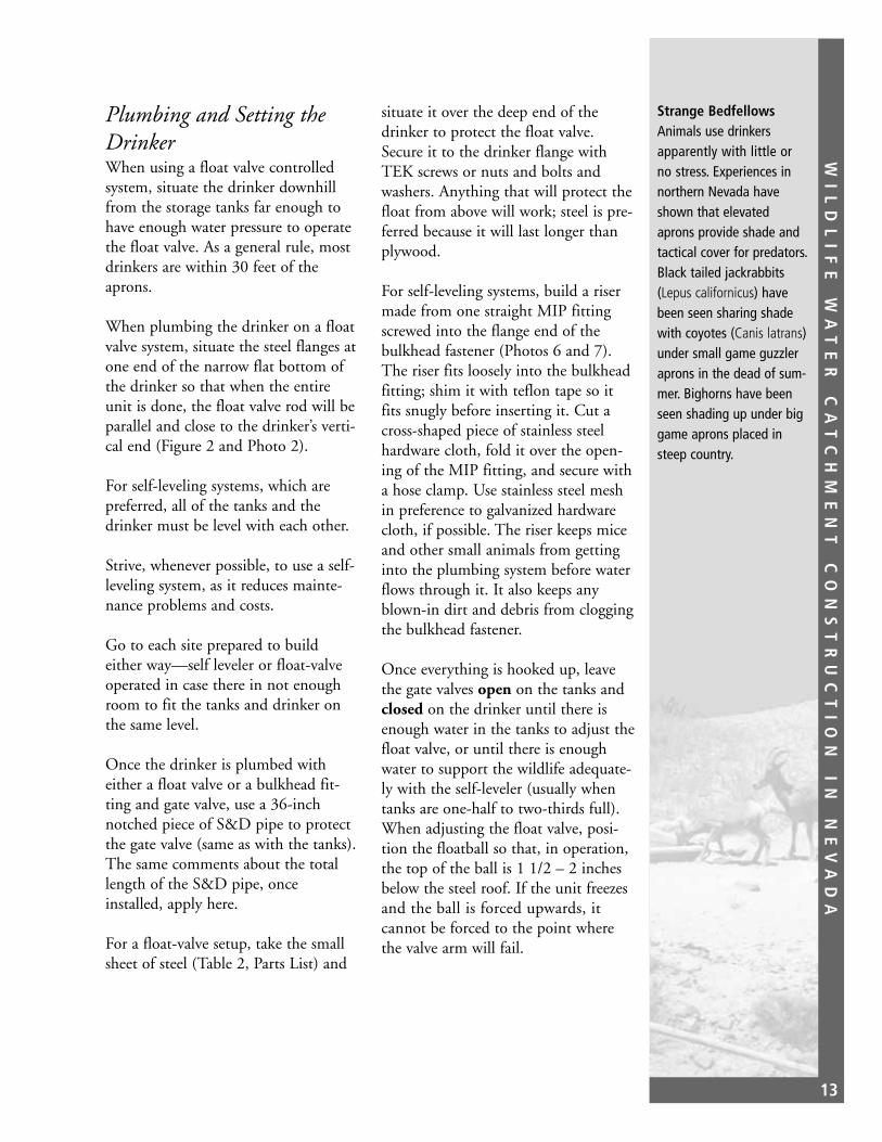
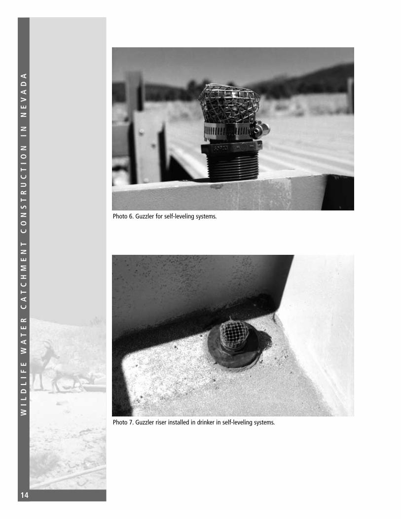
For self-leveling systems, build a risermade from one straight MIP fittingscrewed into the flange end of thebulkhead fastener (Photos 6 and 7).The riser fits loosely into the bulkheadfitting; shim it with teflon tape so itfits snugly before inserting it. Cut across-shaped piece of stainless steelhardware cloth, fold it over the open-ing of the MIP fitting, and secure witha hose clamp. Use stainless steel meshin preference to galvanized hardwarecloth, if possible. The riser keeps miceand other small animals from gettinginto the plumbing system before waterflows through it. It also keeps anyblown-in dirt and debris from cloggingthe bulkhead fastener.
Once everything is hooked up, leavethe gate valves open on the tanks andclosed on the drinker until there isenough water in the tanks to adjust thefloat valve, or until there is enoughwater to support the wildlife adequate-ly with the self-leveler (usually whentanks are one-half to two-thirds full).When adjusting the float valve, posi-tion the floatball so that, in operation,the top of the ball is 1 1/2 – 2 inchesbelow the steel roof. If the unit freezesand the ball is forced upwards, it cannot be forced to the point wherethe valve arm will fail.
Strange BedfellowsAnimals use drinkersapparently with little orno stress. Experiences innorthern Nevada haveshown that elevatedaprons provide shade andtactical cover for predators.Black tailed jackrabbits(Lepus californicus) havebeen seen sharing shadewith coyotes (Canis latrans)under small game guzzleraprons in the dead of sum-mer. Bighorns have beenseen shading up under biggame aprons placed insteep country.
WI
LD
LI
FE
W
AT
ER
C
AT
CH
ME
NT
C
ON
ST
RU
CT
IO
N
IN
N
EV
AD
A
14
Photo 6. Guzzler for self-leveling systems.
Photo 7. Guzzler riser installed in drinker in self-leveling systems.

WI
LD
LI
FE
W
AT
ER
C
AT
CH
ME
NT
C
ON
ST
RU
CT
IO
N
IN
N
EV
AD
A
15
Apron Construction
Beams and UprightsFamiliarize yourself with Figures 3, 4,and 5 and Photo 8 for an overall viewof how the beams and uprights fittogether, and for aprons, sheeting, andupright details.
Each parts list (end of chapter) showsthe number of C-beams required. Anextra beam is added just in case any arebent or damaged. Some of the beamswill be cut into shorter pieces and usedas uprights. Uprights are made by cut-ting the 18-foot C-beams into three6-foot lengths, and then welding two8-inch pieces of 1 1/2-inch angle ironon each side of one end (Figure 5).
A small game guzzler requires a total offive C-beams: three horizontal beamsto hold the apron, plus two more thatwill be cut up into 6-foot-tall uprights.
A big game guzzler requires the samenumber of C-beams per 16 foot x 16foot apron except that the two frontaprons will share one set of uprights(Figures 1 and 3, and Photo 8). And,depending on the site, the second pairof aprons may utilize the rear uprightsof the front pair (Photo 1). So, for abig game guzzler with two 16-foot x32-foot aprons, you will need 15beams (10 support and 5 upright) plusone spare. For two 16-foot x 48-footaprons, you will need 21 beams (14support and 7 upright) plus one spare.
For small game units, take one of the18-foot beams and lay its edge parallelto the opening of the tank mouth andabout even with it. Mark holes to bedug for uprights at each end of thebeam, get the beam out of the way,and dig the holes.
Note that on big game units, twouprights have already been placedbetween the pairs of fiberglass storagetanks.
For big game units it is essential thatthe plumbing crew hook up all tanksto each other as soon as they are in theground, as the front upright betweenpairs of fiberglass tanks usually strad-dles the polypipe connector betweentanks. This central front upright is thekey corner of the first apron.
The back of the horizontal beam (theflat side) must face out so you canhang the gutter on it.
All of the uprights should have theopen part of the C-beam facing towardthe front (Figures 1 and 3).
It is important that the edges of theuprights be flush with the ends of the18-foot beam, and that the uprights bevertical from both directions. Use postlevels for this.
The uprights should be set with theangle iron feet at least 18 to 24 inchesin the ground for stability.
The center uprights will each have twohorizontal beams (for two aprons)attached; simply build one apron high-er that the other for structural integrity(Photo 9).
When the uprights are in place and theC-beam ends are flush so that the holescan be drilled and the bolts installed,use the large C-clamps to secure thebeam to the uprights. The beam mustbe level.
The bottom edge of the beam shouldbe far enough above the tank covers toallow a person entry into the manhole
Helpful HintIf you have only one pair oflarge C-clamps, hold theuprights and beam togeth-er with a TEK screw untilthe hold drilling and bolt-ing is completed. Thisallows use of the C-clampsfor the next beam.

WI
LD
LI
FE
W
AT
ER
C
AT
CH
ME
NT
C
ON
ST
RU
CT
IO
N
IN
N
EV
AD
A
16
Figure 3. Critical measurements for guzzler aprons. Note: These figures are for a 16-foot x 32-foot apron. If a longer apron (48 feet) is used, then key off the right rear upright usingmeasurements for the first 3 beams shown in the drawing (front and 2).
16'-8"
18'-4"
22'-8"
28'-5"
34'-11"
7'-8
" (9
2")
15'-4
"
23'-0
"
30'-8
"
Horizontal beam flat portion (back pf the "C" contacts back of the upright "C"s
Upright
Note: 1. All uprights face downhill toward the front edge of the apron. 2. All diagonal measurements are from the inside intersections of horizontal beams and upright corners. 3. 3 beams = 1 small or 1 big game apron; 5 beams = 1 big game apron. See text.
Note: Drawing not to scale.
TOP VIEW
Front Beam

WI
LD
LI
FE
W
AT
ER
C
AT
CH
ME
NT
C
ON
ST
RU
CT
IO
N
IN
N
EV
AD
A
17
Figure 4. Apron and sheeting details.
Sheeting
Prevailing wind
Tek screw
Beam
Sheet overlap
16'-8"
Beam end flush with upright
Beam
3/8" Bolts(Note hole pattern)
Common upright
Note: Drawings not to scale
Big Red's Creative Building Systems 7.2 supra rib has 7 troughs;install Tek screws in troughs 1, 4, and 7.

WI
LD
LI
FE
W
AT
ER
C
AT
CH
ME
NT
C
ON
ST
RU
CT
IO
N
IN
N
EV
AD
A
18
Figure 5. Upright details.
Upright
Angle iron
TOP VIEW
SIDE VIEWFRONT VIEW
Upright Angle iron
WI
LD
LI
FE
W
AT
ER
C
AT
CH
ME
NT
C
ON
ST
RU
CT
IO
N
IN
N
EV
AD
A
19
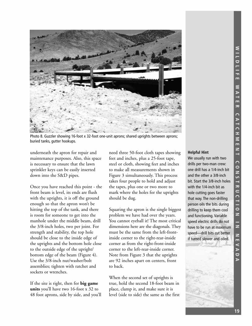
Photo 8. Guzzler showing 16-foot x 32-foot one-unit aprons; shared uprights between aprons;buried tanks, gutter hookups.
underneath the apron for repair andmaintenance purposes. Also, this spaceis necessary to ensure that the lawnsprinkler keys can be easily inserteddown into the S&D pipes.
Once you have reached this point - thefront beam is level, its ends are flushwith the uprights, it is off the groundenough so that the apron won’t behitting the top of the tank, and thereis room for someone to get into themanhole under the middle beam, drillthe 3/8-inch holes, two per joint. Forstrength and stability, the top holeshould be close to the inside edge ofthe uprights and the bottom hole closeto the outside edge of the upright/bottom edge of the beam (Figure 4).Use the 3/8-inch nut/washer/boltassemblies; tighten with ratchet andsockets or wrenches.
If the site is right, then for big gameunits you’ll have two 16-foot x 32 to48 foot aprons, side by side, and you’ll
need three 50-foot cloth tapes showingfeet and inches, plus a 25-foot tape,steel or cloth, showing feet and inchesto make all measurements shown inFigure 3 simultaneously. This processtakes four people to hold and adjustthe tapes, plus one or two more tomark where the holes for the uprightsshould be dug.
Squaring the apron is the single biggestproblem we have had over the years.You cannot eyeball it! The most criticaldimensions here are the diagonals. Theymust be the same from the left-front-inside corner to the right-rear-insidecorner as from the right-front-insidecorner to the left-rear-inside corner.Note from Figure 3 that the uprightsare 92 inches apart on centers, frontto back.
When the second set of uprights istrue, hold the second 18-foot beam inplace, clamp it, and make sure it islevel (side to side) the same as the first
Helpful HintWe usually run with twodrills per two-man crew:one drill has a 1/4-inch bitand the other a 3/8-inchbit. Start the 3/8-inch holeswith the 1/4-inch bit ashole cutting goes fasterthat way. The non-drillingperson oils the bits duringdrilling to keep them cooland functioning. Variablespeed electric drills do nothave to be run at maximumspeed—drill bits cut betterif turned slower and oiled.
WI
LD
LI
FE
W
AT
ER
C
AT
CH
ME
NT
C
ON
ST
RU
CT
IO
N
IN
N
EV
AD
A
20
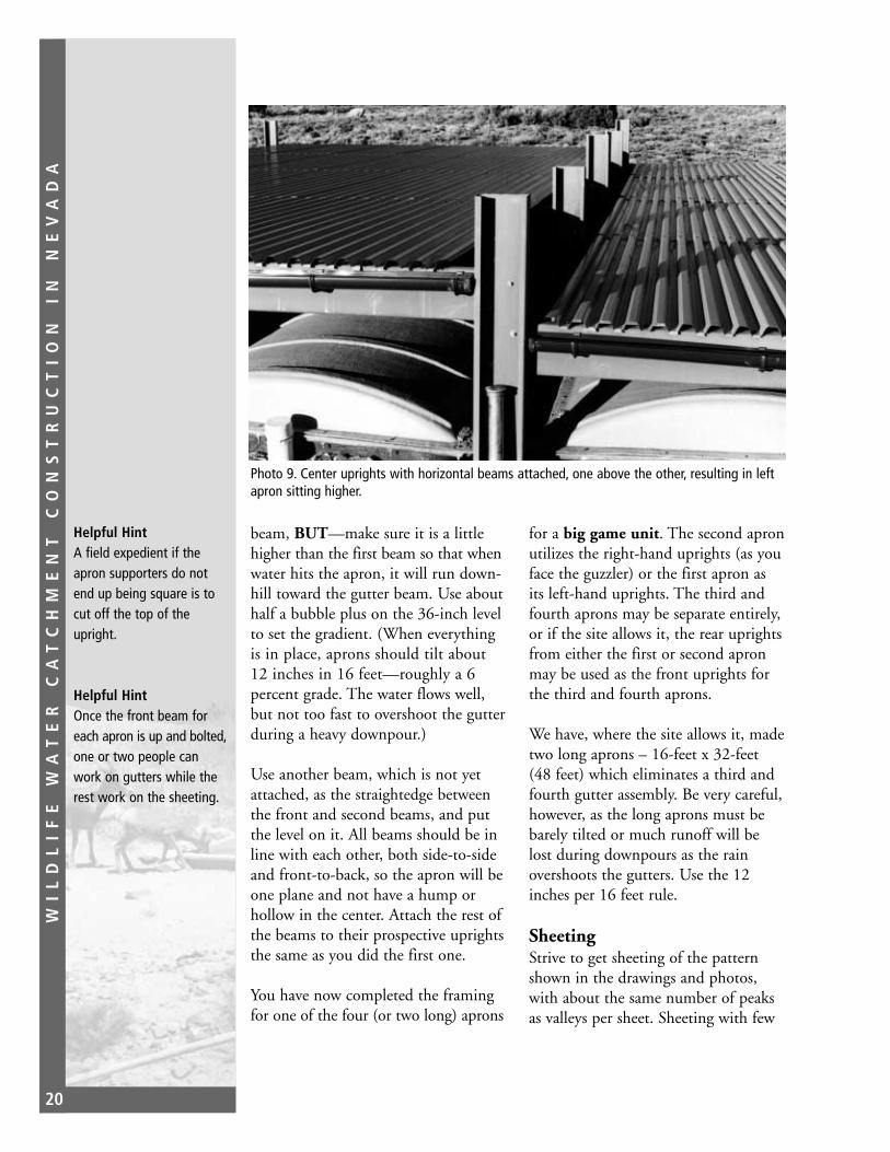
Photo 9. Center uprights with horizontal beams attached, one above the other, resulting in leftapron sitting higher.
beam, BUT—make sure it is a littlehigher than the first beam so that whenwater hits the apron, it will run down-hill toward the gutter beam. Use abouthalf a bubble plus on the 36-inch levelto set the gradient. (When everythingis in place, aprons should tilt about12 inches in 16 feet—roughly a 6percent grade. The water flows well,but not too fast to overshoot the gutterduring a heavy downpour.)
Use another beam, which is not yetattached, as the straightedge betweenthe front and second beams, and putthe level on it. All beams should be inline with each other, both side-to-sideand front-to-back, so the apron will beone plane and not have a hump orhollow in the center. Attach the rest ofthe beams to their prospective uprightsthe same as you did the first one.
You have now completed the framingfor one of the four (or two long) aprons
for a big game unit. The second apronutilizes the right-hand uprights (as youface the guzzler) or the first apron asits left-hand uprights. The third andfourth aprons may be separate entirely,or if the site allows it, the rear uprightsfrom either the first or second apronmay be used as the front uprights forthe third and fourth aprons.
We have, where the site allows it, madetwo long aprons – 16-feet x 32-feet(48 feet) which eliminates a third andfourth gutter assembly. Be very careful,however, as the long aprons must bebarely tilted or much runoff will belost during downpours as the rainovershoots the gutters. Use the 12inches per 16 feet rule.
SheetingStrive to get sheeting of the patternshown in the drawings and photos,with about the same number of peaksas valleys per sheet. Sheeting with few
Helpful HintA field expedient if theapron supporters do notend up being square is tocut off the top of theupright.
Helpful HintOnce the front beam foreach apron is up and bolted,one or two people canwork on gutters while therest work on the sheeting.

WI
LD
LI
FE
W
AT
ER
C
AT
CH
ME
NT
C
ON
ST
RU
CT
IO
N
IN
N
EV
AD
A
21
humps and more flat area are structurallymuch weaker when snow loading is anissue, as it is in northern Nevada.
Start with the lower and middlebeams, overlapping the sheets by onehump, side to side. Note the commenton the drawings about the prevailingwind (Figure 4).
The front edge of the sheeting shouldoverhang the front beam face by about1 inch (no more) so water drops rightinto the gutter and doesn’t run downthe face of the beam.
The front edge of the apron should bea straight line. If it is not, jiggle thesheets around until it is and the over-hang still remains just an inch.
When the front edge of the sheets andthe beam are 1 inch apart all the wayacross, and the sheeting is centeredbetween the uprights, secure the sheet-ing to the first beam only with TEKscrews (Figure 3). This will make itmuch easier to complete the apron,regardless of length.
Now, lay on the second set of sheeting,making sure that the downstream orlower edge comes right to the down-stream angle of the middle beam’s faceand edge. Jiggle the sheets again if youhave to.
If the beams and uprights are square,then the sheeting should go on with alittle bit of room to spare, and nocutting of the sheeting will be requiredwhere it butts up against the uprights.Now it’s time to mark where the restof the TEK screws will go. Take thechalk line, center it on the top (hori-zontal) edge of each beam, snap it,and start installing the TEK screws.
Do the front edge first (if you haven’talready), then the middle beam, thenthe third beam, and so on. When youget to the middle beams, you’ll have tostand on them and the sheeting to putin the TEK screws. Stay centered onthe beams—no more than a foot or soto each side of center as the sheeting isnot very strong.
Use three TEK screws to attach each piece of sheeting to each beam(Figure 4). The rubber washed underthe head of each TEK screw keepswater from flowing down the drill holeand through the beam. You’ll need a3/8-inch magnetic socket on the screwgun to install the #14 TEK screws.
One last (important) thing: bend thetroughs of the front sheet down just alittle using a Crescent wrench so thewater will drop better into the gutterduring light rainfall. If thunderstormsprovide some of the water, use 1 1/2-inch x 1 1/2-inch aluminum flashinginstalled so the vertical side slows highflows and forces the water down intothe gutter.
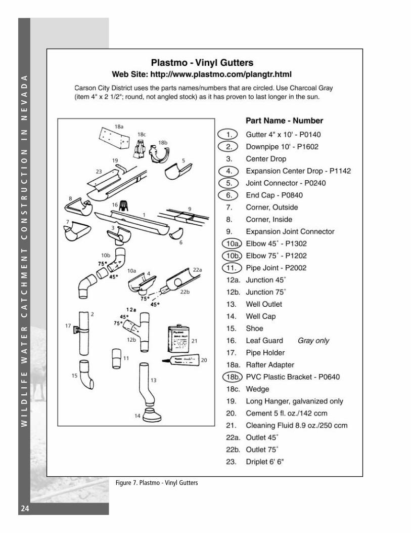
Gutter ConstructionFor an overall view of gutter construc-tion, examine Figure 6, Photos 10 and11, and the Plastmo Vinyl Gutterssheet (Figure 7).
Galvanized gutter materials were usedin earlier catchments, but the plasticPlastmo that is currently used snapstogether and is as durable. (Two Plastmogutters have lasted 19 years to date.)
Place the dropout (Figure 6 and Photo11) so that it will be about 10 feetfrom one end of the apron and 5 feetfrom the other. Ten feet of gutter, plus
Helpful HintPlastmo gutter materials areround or rounded. Avoidbuying squarish gutters,pipe, and dropouts if youcan - they are much moredifficult to work with.
WI
LD
LI
FE
W
AT
ER
C
AT
CH
ME
NT
C
ON
ST
RU
CT
IO
N
IN
N
EV
AD
A
22
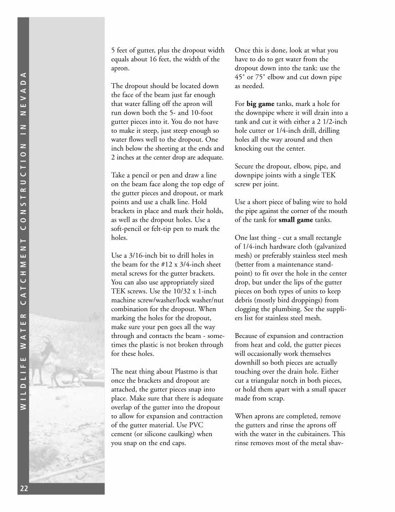
5 feet of gutter, plus the dropout widthequals about 16 feet, the width of theapron.
The dropout should be located downthe face of the beam just far enoughthat water falling off the apron willrun down both the 5- and 10-footgutter pieces into it. You do not haveto make it steep, just steep enough sowater flows well to the dropout. Oneinch below the sheeting at the ends and2 inches at the center drop are adequate.
Take a pencil or pen and draw a lineon the beam face along the top edge ofthe gutter pieces and dropout, or markpoints and use a chalk line. Holdbrackets in place and mark their holds,as well as the dropout holes. Use asoft-pencil or felt-tip pen to mark theholes.
Use a 3/16-inch bit to drill holes inthe beam for the #12 x 3/4-inch sheetmetal screws for the gutter brackets.You can also use appropriately sizedTEK screws. Use the 10/32 x 1-inchmachine screw/washer/lock washer/nutcombination for the dropout. Whenmarking the holes for the dropout,make sure your pen goes all the waythrough and contacts the beam - some-times the plastic is not broken throughfor these holes.
The neat thing about Plastmo is thatonce the brackets and dropout areattached, the gutter pieces snap intoplace. Make sure that there is adequateoverlap of the gutter into the dropoutto allow for expansion and contractionof the gutter material. Use PVCcement (or silicone caulking) whenyou snap on the end caps.
Once this is done, look at what youhave to do to get water from thedropout down into the tank: use the45˚ or 75˚ elbow and cut down pipeas needed.
For big game tanks, mark a hole forthe downpipe where it will drain into atank and cut it with either a 2 1/2-inchhole cutter or 1/4-inch drill, drillingholes all the way around and thenknocking out the center.
Secure the dropout, elbow, pipe, anddownpipe joints with a single TEKscrew per joint.
Use a short piece of baling wire to holdthe pipe against the corner of the mouthof the tank for small game tanks.
One last thing - cut a small rectangleof 1/4-inch hardware cloth (galvanizedmesh) or preferably stainless steel mesh(better from a maintenance stand-point) to fit over the hole in the centerdrop, but under the lips of the gutterpieces on both types of units to keepdebris (mostly bird droppings) fromclogging the plumbing. See the suppli-ers list for stainless steel mesh.
Because of expansion and contractionfrom heat and cold, the gutter pieceswill occasionally work themselvesdownhill so both pieces are actuallytouching over the drain hole. Eithercut a triangular notch in both pieces,or hold them apart with a small spacermade from scrap.
When aprons are completed, removethe gutters and rinse the aprons offwith the water in the cubitainers. Thisrinse removes most of the metal shav-

WI
LD
LI
FE
W
AT
ER
C
AT
CH
ME
NT
C
ON
ST
RU
CT
IO
N
IN
N
EV
AD
A
23
ings created during installation of TEKscrews, which drill their own holes.
The gutters are the weakest link ingetting water into the tanks. Protect
them with several steel fence posts andfield fencing to keep large animalsaway from them.
Note: Drawing not to scale.
Steel upright10' gutter section
Apron
5' gutter section
Center drop
End cap
Tank
45˚ or 72˚ elbow
Downpipe 10' long cut to fit
Use 8 brackets and 2 end caps per gutter assembly;tank is buried, if possible, up to lid.
3/8" Bolts
Brackets
Front beam of apron
Tank lid
Figure 6. Carson City BLM game guzzler gutter details.
WI
LD
LI
FE
W
AT
ER
C
AT
CH
ME
NT
C
ON
ST
RU
CT
IO
N
IN
N
EV
AD
A
24
Figure 7. Plastmo - Vinyl Gutters

WI
LD
LI
FE
W
AT
ER
C
AT
CH
ME
NT
C
ON
ST
RU
CT
IO
N
IN
N
EV
AD
A
25
Photo 10. Guzzler gutter parts, left to right: center drop; gutter bracket; pipe connector, 45˚elbow; 75˚ elbow (“L”).
Photo 11. Guzzler gutter details: center drop and PVC gutter brackets are installed; pieces of thesnap-in gutter lie on apron.

WI
LD
LI
FE
W
AT
ER
C
AT
CH
ME
NT
C
ON
ST
RU
CT
IO
N
IN
N
EV
AD
A
26
FencesTable 2, Materials/Parts List for BigGame Guzzler and Fence, includes partsfor a buck and rail fence and for a 4-5strand barbed and smooth wire fence.
Buck and Rail FenceWe evolved to the buck and rail fencein the Carson City District because ofthe cattle and wild horses in the areaswhere we construct the big game unitsfor desert bighorn sheep. Study Figure8 and Photo 12 for constructiondetails.
One advantage of the buck and railfence is that no post holes have to bedug. A disadvantage is the sheer bulkof the wood posts and rails duringtransport and the fact that they weighabout 2 tons if you are using helicoptertransport.
For this fence, staple the barbed wirejust below the top rail to discouragehorses from trying to lift this rail withtheir noses. (This uses about 320 feet ofthe barbed wire, which is not includedin the materials list.) Also, be sure tonail the 4-foot-long 2-by-4s to thelower legs of the bucks so the buckswon’t collapse.
Smooth Wire/4-5 Strand BarbedWire FenceWe have used standard BLM-specantelope “Type B” fences to protectguzzlers in antelope areas where horsesare not a problem and for some smallgame guzzlers. The fences around sev-eral antelope guzzlers are 300 feet on aside, so that a minimum of two acreswas enclosed. Wires from ground level
up should measure 16-inch smooth,then 22-, 30-, and 42-inch barbed. Wehave found, however, that antelope willuse the much smaller buck and railfence and the same guzzlers where onlythe drinkers are protected with weldedpipe fence.
In 1995, we used this same fence, onlymuch shorter, to protect bighorn unitswhere horses were not a problem. Wirespacing there (Photo 13) is 20-35-39-43 inches from the ground. The bottomwire is smooth and the rest are barbed.
While these fences are anchored entirelyin the ground by standard 5 1/2-foot“T” posts, and each of these must bedriven in by hand, the fences still goup much faster than the buck-and-railtypes.
The smaller bulk of materials alsomakes transporting much easier. Notethat we are using “EZ” panels for cor-ners. These are easy to install andappear to do the job adequately.
Small Game Guzzler FenceFencing is much simpler for smallgame guzzlers. Where these have to beprotected from cows rubbing againstthe apron or uprights, we simply havestretched barbed wire around theuprights and anchored the wire tothem. You can also use regular 3-postcorners (Or EZ panels) in either asquare or triangle configuration toprotect the small game units.
When the job is complete, police thearea for any litter and seed the areainside the fence with native grass, forb,and shrub species.

WI
LD
LI
FE
W
AT
ER
C
AT
CH
ME
NT
C
ON
ST
RU
CT
IO
N
IN
N
EV
AD
A
27
Figure 8. Carson City BLM big game guzzler fence details, buck-and-rail type.
•
•
••
••
•
•
x x x x x x x x x x x x x x x x x x x
••
•
•
••
••
•
Pattern for straight stretches of fence—alternating overlap of rails.
Pattern for curved sections of fence—top and bottom rails overlap on same buck.
Note: Use 11" lengths of all-thread for all pins,plus 1/2" flat washers and nuts. Peen threadsonce nuts are tightened so they won’t work looseand off as posts dry and wind blows. Lock washers are not needed here. Smooth wire keeps most calves out;barbed wire keeps horses from lifting rails. 2 x 4’s keepbuck legs from collapsing. Pre-drill holes in 2 x 4’sso wood won’t split when driving spikes.
Rails are 16' long; bucks are on 7' centers.
•
• •
16' wooden rail
5" x 6 1/2' wood post
All-thread
Rails
2"x4"x4'
xBarbed wire
30"20"
Note: Drawings not to scale.

WI
LD
LI
FE
W
AT
ER
C
AT
CH
ME
NT
C
ON
ST
RU
CT
IO
N
IN
N
EV
AD
A
28
Photo 12. Completed big game guzzler in northern Nevada, consisting of water collectingaprons, buried tanks, drinker surrounded by rocks, and buck-and-rail fence.
Photo 13. Barbed and smooth wire (bottom strand only) using steel “T” posts and “EZ” panelcorners. Rocks (piled or wired on) strengthen the corner.

WI
LD
LI
FE
W
AT
ER
C
AT
CH
ME
NT
C
ON
ST
RU
CT
IO
N
IN
N
EV
AD
A
29
Loose EndsGo back to the big game guzzler afterit rains or snows sufficiently. Open thegate valve for the drinker and adjustthe float valve if there is one.
Some readers may question why weuse so many different parts for plumb-ing instead of using PVC stiff pipe andfittings. Early use of PVC gave usnothing but grief, and we went withwhat we use now because individualparts are easily replaced. Another rea-son for the many small parts is thatthey are more easily carried intoremote guzzler sites than PVC pipe,and many of the bighorn sheep unitsare well away from roads.
Every part that is used in constructionof these guzzlers, large and small, is“off-the-shelf ” and may be purchasedor ordered from virtually anywhere.Even the tanks and steel have at leasttwo suppliers each.
We are currently experimenting withone antelope guzzler using all PVC(underground). This is a site that wecan drive to.
The parts for an additional fiberglassstorage tank are as follows: one tank,one bulkhead fastener, one 90˚ MIP,one gate valve, one barbed “T” or “L,”five or six stainless steel hose clamps,two straight MIPs, one 36-inch pieceof sewer and drain pipe, one 4-inch
PVC cap, and several feet of Teflontape.
The parts needed for a stand-alonesingle 16 foot x 16 foot apron are listedin Table 1, except that a solid roofreplaces the open-end roof and walk-down ramp.
Comments onSubstitutionsDO NOT let a salesman tell youthat 26-gauge steel is equivalent to a24-gauge steel. The difference in weight-bearing capacity is approximately 25 percent on the 8-foot lengths thatare used.
You can order the big game tank lidsjust as they are shown in the construc-tion drawings. Don’t let people sell youlids that serve as catchment apronsthemselves.
The manhole covers are held in placewith 3 or 4 self-threading screws, not8 or 10 nuts and bolts.
Plan adequate lead time when orderingparts, especially steel and fiberglass.Plan on six to eight week deliverytimes for these and shorter times forsmaller parts. If anything has to go outfor bid, double the time. The best betis to order everything three monthsprior to construction.
WI
LD
LI
FE
W
AT
ER
C
AT
CH
ME
NT
C
ON
ST
RU
CT
IO
N
IN
N
EV
AD
A
30
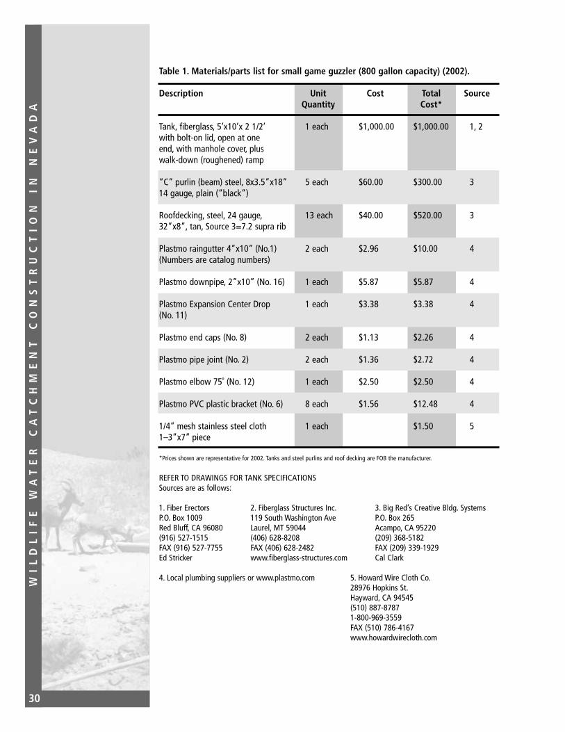
Table 1. Materials/parts list for small game guzzler (800 gallon capacity) (2002).
Description Unit Cost Total SourceQuantity Cost*
Tank, fiberglass, 5’x10’x 2 1/2’ 1 each $1,000.00 $1,000.00 1, 2with bolt-on lid, open at oneend, with manhole cover, pluswalk-down (roughened) ramp
“C” purlin (beam) steel, 8x3.5”x18” 5 each $60.00 $300.00 314 gauge, plain (“black”)
Roofdecking, steel, 24 gauge, 13 each $40.00 $520.00 332”x8”, tan, Source 3=7.2 supra rib
Plastmo raingutter 4”x10” (No.1) 2 each $2.96 $10.00 4(Numbers are catalog numbers)
Plastmo downpipe, 2”x10” (No. 16) 1 each $5.87 $5.87 4
Plastmo Expansion Center Drop 1 each $3.38 $3.38 4(No. 11)
Plastmo end caps (No. 8) 2 each $1.13 $2.26 4
Plastmo pipe joint (No. 2) 2 each $1.36 $2.72 4
Plastmo elbow 75˚ (No. 12) 1 each $2.50 $2.50 4
Plastmo PVC plastic bracket (No. 6) 8 each $1.56 $12.48 4
1/4” mesh stainless steel cloth 1 each $1.50 51–3”x7” piece
*Prices shown are representative for 2002. Tanks and steel purlins and roof decking are FOB the manufacturer.
REFER TO DRAWINGS FOR TANK SPECIFICATIONSSources are as follows:
1. Fiber Erectors 2. Fiberglass Structures Inc. 3. Big Red’s Creative Bldg. Systems P.O. Box 1009 119 South Washington Ave P.O. Box 265Red Bluff, CA 96080 Laurel, MT 59044 Acampo, CA 95220(916) 527-1515 (406) 628-8208 (209) 368-5182FAX (916) 527-7755 FAX (406) 628-2482 FAX (209) 339-1929Ed Stricker www.fiberglass-structures.com Cal Clark
4. Local plumbing suppliers or www.plastmo.com 5. Howard Wire Cloth Co.28976 Hopkins St.Hayward, CA 94545(510) 887-87871-800-969-3559FAX (510) 786-4167www.howardwirecloth.com

WI
LD
LI
FE
W
AT
ER
C
AT
CH
ME
NT
C
ON
ST
RU
CT
IO
N
IN
N
EV
AD
A
31
Table 2. Materials/parts list for big game guzzler (4,000 gallon capacity) plus fence(2002)
Description Unit Cost* Total SourceQuantity Cost*
Tank, fiberglass, 5’x10’ x 2 1/2’; with 5 each $1,000 $5,000 1, 2bolt-on lid & no plumbing, but with manhole cover OR
Tank, Boss Polypropylene 16’ x 8’ x 2’ 2 each $3,400 $6,800 8Flat Root, 1 piece, 2,000 gallon cap
Drinker, fiberglass, 36” x 72” x 30” 1 each $225.00 $225.00 2
“C” purlin (beam), steel, 8” x 3 1/2”x 18’ 23 each $63.36 $1457.28 314 gauge, plain (15 beams + 20 uprights (minimum) + 1 spare)
Roofdecking, steel, 24 gauge, 36” x 8” 74 each $36.32 $2687.68 3Source 3 = 7.2 supra-rib
Angle iron, steel, 1 1/2” x 1 1/2” x 8 30 ft. $1.10 $33.00 4Buy in 10 ft. lengths, then cut
1 1/2” standard thread brass gate 6 each $36.74 $220.44 4valve, Grinell 3000 or equiv.
90˚ plastic 1 1/2” barbed L 2 each $1.73 $3.46 4(1 1/2 insert x 1 1/2 insert Poly 90)
1 1/2” barbed T 4 each $2.65 $10.60 4(1 1/2 insert Poly T)
1 1/2” plastic bulkhead fastener 6 each* $8.99 $53.94 4(1 1/2 PVC bulkhead)* for self-leveling system; 5 for float operatedsystem
1 1/2” MIP plastic barbed adapter 13 each* $0.87 $11.31 4(1 1/2 MIP x insert poly adapter)*10 for float operated system
4” x 10’ sewer & drain (S&D) pipe, 2 each $4.05 $8.10 4non-perforated (solid)
4” S&D caps 6 each $0.66 $3.96 4
1 1/2” Black polypipe, 100 ft. roll 1 each $127.77 $127.77 4IPS 100 lbs. Pressure, potable water
1 1/2” stainless steel hose clamps 50 each $0.90 $45.00 4
Teflon tape, 3/4” wide roll 2 each $2.50 $5.00 4

WI
LD
LI
FE
W
AT
ER
C
AT
CH
ME
NT
C
ON
ST
RU
CT
IO
N
IN
N
EV
AD
A
32
Table 2 (cont)
Description Unit Cost* Total SourceQuantity Cost*
Sprinker Key, 24” 1 each $3.00 $3.00 4
Silicone caulking, non-toxic (for 1 tubeaquariums) to fit regular (10 oz) $8.75 $8.75 5caulking gun
Plastmo raingutter 4” x 10’ (No. 1) 8 each $2.96 $23.68 4
Plastmo downpipe, 2” x 10’ (No. 16) 4 each $5.87 $23.28 4
Plastmo Expansion center drop 4 each $3.38 $13.52 4(No. 11)
Plastmo end caps (No. 8) 8 each $1.13 $9.04 4
Plastmo pipe joint (No. 2) 8 each $1.36 $10.88 4
Plastmo elbow 75˚ (No. 12) 4 each $2.50 $10.00 4
Plastmo PVC plastic bracket (No. 6) 34 each $1.56 $53.04 4
TEK Screws, #14 x 1’ sealer 300 each $160./M $48.00 4
Hex bolts, grade 2 plated steel, 65 each $15.00/C $10.00 43/8” x 1” x 16tpi
3/8” x 16 tpi nuts, plated steel 65 each $5.00/C $3.25 4
3/8” plated steel flat washers 130 each $0.05/C $6.50 4
3/8” plated steel lock washers 65 each $0.05 $3.25 4
10/32 x 1” machine screw with fender 8 units $1.00 $9.00 4washer, lock washer, & nut
No. 12 x 3/4” sheet metal screws box of 100 $9.00 4
1/4” mesh stainless steel cloth 1 square ft. $2.00 7(3, 3” x 7”pieces)
Additional Parts Required For Float Operated System:
1 1/2” brass float valve with 18” rod, 1 each $85.00 $85.00 4swivel and 6” copper float(no plastic)
1 1/2” standard thread steel floor 2 each $5.00 $10.00 4flange, 4 hole pattern

WI
LD
LI
FE
W
AT
ER
C
AT
CH
ME
NT
C
ON
ST
RU
CT
IO
N
IN
N
EV
AD
A
33
Table 2 (cont)
Description Unit Cost* Total SourceQuantity Cost*
1 1/2” x 3 1/2” steel nipple 1each $1.75 $1.75 4
5/16” x 18 x 1 1/2” stainless steel cap 5 each $8.00 4screw, + 5/16” and 18 stainless steelnut, + 5/16” s.s. lock washer, + 5/16” s.s. flat washer (10)
1/8” – 1/4” steel plate to protect 1 each $15.00 $15.00 4
Buck And Rail Fence Parts:
Treated wood post, 6 1/2’ x 5-6” 92 each $5.00 $552.00 4
Rail, wood, 16’ x 3-4” 46 inch $7.50 $345.00 4
Drive Screw fence nails 2 bundle $6.00 $12.00 4(50 nails each)
2” x 4” x 4’ wood 46 each $2.00 $92.00 4
All-thread, steel, 1/2” x 11” 150 each $0.80/ft $110.00 4
All-thread, steel, 1/2” x 13” 50 each $0.80 $44.00 4
Washer, flat, 1/2”, plated steel 400 each $0.12 $48.00 4
Nut, 1/2”, plated steel to fit all thread 400 each $0.13 $52.00 4
Fence staples 100 each $0.02 $2.00 4
All Steel Fence Parts:
Easy Fence panels/Grace Combinations 8 each $42.00 $336.00 6
Steel “T” post (need 5-6/corner, 24 each $2.75 $66.00 4plus any line posts) (X) each $2.75 4
Barbed wire roll (= 1,320 ft. long) 1-4 rolls $33.00 $33.00 to 41-4 rolls $132.00
Fence clips (package of 50) 1-3 packs $1.50 $150 to 4$4.50
Fens stays, 30” each $0.30 4
*Prices shown are representative for 2002. Tanks, steel purlins, and roofdecks are FOB the manufacturer.

WI
LD
LI
FE
W
AT
ER
C
AT
CH
ME
NT
C
ON
ST
RU
CT
IO
N
IN
N
EV
AD
A
34
Table 2 (cont)
REFER TO DRAWINGS FOR TANK AND STEEL SPECIFICATIONS
1. Fiber Erectors 2. Fiberglass Structures, Inc. 3. Big Red’s Creative Bldg.P.O. Box 1009 119 South Washington Ave SystemsRed Bluff, CA 96080 Laurel, MT 59044 P.O. Box 265(916) 527-1515 (406) 628-8208 Acampo, CA 95220FAX (916) 527-7755 FAX (406) 628-2488 (209) 368-5182Ed Stricker www.fiberglass-structures.com FAX (209) 339-1929
Cal Clark
4. Local plumbing, fastener, 5. GE (General Electric) 6. Easy Fenceand fencing suppliers such Caulking, #RTV108, form 408 South 900 Westas R Supply, Reno, NV. R.S. Hughes Blackfoot, ID 83221
P.O. Box 292933 (208) 782-1177Sacramento, CA 95827 www.easyfence.com(916) 737-7484For nearest availability, call GE at1-800-255-8886 and as for a technical rep
7. Howard Wire Cloth Co. 8. Boss Tanks28976 Hopkins St. P.O. Box 5689Hayward, CA 94545 Elko, NV 89802(510) 887-8787 (775) 738-2677FAX (510) 786-4167 FAX (775) 738-23671-800-969-3559 MOBILE (775) 777-5631www.howardwirecloth.com www.bosstanks.com

WI
LD
LI
FE
W
AT
ER
C
AT
CH
ME
NT
C
ON
ST
RU
CT
IO
N
IN
N
EV
AD
A
35
Table 3. Equipment/tools checklist for guzzler and fence construction
1. 2 portable generators (powerful enough to run 2, 1/2-inch drills each, simultaneously - oursare 18.5 amp, 2400 watt)
2. Backup generator
3. Extra gasoline (for generators and rock drill–4 gallons minimum)
4. Tarps (to put generators on when working to keep them out of the dirt–also to coverequipment or volunteers if it rains or snows or if everything sits at a site for several weeksbetween helicopter slinging and actual construction)
5. Small propane torch (preferably self-igniting with an extra gas bottle for heating polypipe)
6. 2 to 4, 1/2-inch variable speed (0-850 rpm) hand-held drills with reversing gear (We use 4 Milwaukee 0234-1 as they are professional quality and last longer than Black and Decker,etc. Not cheap, but worth it! You can also use 3/8-inch variable speed drills, Milwaukee 0-288-1)
7. 2 drill bits each of the following: 3/16-inch, 1/4-inch, 3/8-inch. (We usually buy 1 of eachper job. The cobalt type is preferred because they last longest)
8. High speed (0-2500 rpm) screw gun (for installing TEK screws/apron to beam; we use aMilwaukee 6798-1 with 3/8-inch magnetic socket)
9. 1, 2 3/8-inch hole cutter (for bulkhead fasteners/fiberglass tanks; fits any electric drill)
10. 1, 2 1/2-inch hole cutter (for draining gutters into tanks via Plastmo pipe; make sure it isstout enough to cut through roof decking
11. Rechargeable 9.6 volt or greater 3/8-inch cordless drill with 2 each 1/4-inch and 5/16-inchApex heads (for plumbing and gutters)
12. 50-foot heavy duty extension cord - at least 1 per drill and screw gun. We use GFI (GroundFault Interrupter) cords, which automatically break the circuit if the drills short out. Each ofthese will accommodate 2 drill/cord combinations.
13. Oilers for cooling the drill bits.
14. 1 quart of 10-30 weight oil (nothing thicker) for oilers
15. 2 pair, 4-inch channel lock pliers (for plumbing)
16. Hacksaw (for cutting Plastmo gutter and tubing; a 24 tooth/inch blade is adequate)
17. 6, 5-gallon cubitainers filled with water (for drinking and washing the apron - more if youwish)
18. Caulking gun (for silicone caulking)
19. Chalk line (for marking TEK screw locations on the apron and gutter locations on the frontbeam of each apron)

WI
LD
LI
FE
W
AT
ER
C
AT
CH
ME
NT
C
ON
ST
RU
CT
IO
N
IN
N
EV
AD
A
36
Table 3. (cont)
20. 1, 25-foot steel tape
21. 3, 50-foot cloth tapes
22. 3/8-inch drive ratchet with 2-inch extension and the following sockets: 3/4-inch deepset(for 1/2-inch fence nuts); 9/16-inch (for 3/8-inch stock for apron supports); 1/2 -inch (for5/16-inch cap screws and nuts on drinker flanges when a float valve is used) (Get two ofeverything)
23. Open end/box combination wrenches in 9/16-inch, 3/4-inch and 7/16-inch (to complementratchets and sockets)
24. Large C-clamps, 10-inch size, minimum of 2 but preferably 6 (for holding horizontal beamsprior to drilling)
25. 36-inch level (for hole and apron)
26. 3 claw hammers
27. A center punch
28. 1 to 2 properly fitting screwdrivers (for machine screws and stainless steel hose clamps;check clamps - they may require a socket or nut driver instead)
29. 2, 5/16-inch nut drivers (better than screwdrivers for hose clamps)
30. 6 to 8 shovels (for digging)
31. 1 to 2 flat shovels (for hole leveling)
32. 1 to 2 Pulaskis (for brush clearing and trenching)
33. A pick for trenching
34. 1 to 2 McLeods (combination heavy-duty rake/hoe; for hole smoothing)
35. 1 rake (for hole smoothing)
36. A 4-foot piece of a 2 by 4 (for hole leveling)
37. 2-4 Pry bars/tampers (for upright; holes/rocks)
38. Vise grips/crescent wrench
39. Heavy gloves (for all personnel)
40. Plastic goggles (as needed)
41. 1, 20-man first aid kit

WI
LD
LI
FE
W
AT
ER
C
AT
CH
ME
NT
C
ON
ST
RU
CT
IO
N
IN
N
EV
AD
A
37
Table 3. (cont)
42. 24- or 30- inch lawn sprinkler tool (for opening and closing gate valves - leave this at thesite tucked up into the backside of one of the front beams)
43. Tin snips (for cutting galvanized or steel hardware cloth)
44. Fiberglass repair kit including file (for repairing fiberglass tanks/drinker if necessary)
45. 2 to 3 pairs of fencing pliers
46. 2, 12-inch x 9/16-inch drill bits (for wood posts in wooden fences only)
47. 2 to 3 clam shell post hole diggers (for upland game guzzler fence posts and apronuprights)
48. Steel post drivers (for steel post and wire fences)
49. A bow saw for wooden fences
50. Cold chisel (to peen threads on all-thread after nuts are installed on wood fences)
51. Chisel (in case all-thread pieces are too short or the wood is too thick)
52. Post level (4-6)
53. Heavy twine and 4 steel rebar pins, 18-24-inches long for laying out storage tank holeand/or apron boundaries
54. 2 wide-tipped and 2 fine-tipped black felt tip pens for marking holes (for gutters)
55. 50 or so disposable drinking cups
OPTIONAL EQUIPMENT:
1. Gasoline-powered auger (for post holes, upright holes, blasting, etc)
2. Rock drill (Pionjar/Wacker - for drilling blasting holes and the trench for plumbing on biggame guzzlers, if necessary; plus tough holes for uprights)
3. Backhoe (either rubber tired or tracked)
4. Bobcat earthmover with front-end loader and power auger (Both have been worth theirweight in gold at tough digging sites)

WI
LD
LI
FE
W
AT
ER
C
AT
CH
ME
NT
C
ON
ST
RU
CT
IO
N
IN
N
EV
AD
A
38
Table 4. Big game guzzler general checklist
1. Job folder and checklist completed prior to construction
2. Notification: construction date(s) and maps to constituent groups, volunteers, and individuals, prepared/mailed/delivered
3. Signs; steel posts/post pounder/duct tape/yellow flagging/paper plates/wide felt-tip pens
4. Working drawings/spec sheets: three copies minimum to job site
5. Lists: parts/tools
6. Helicopter operation: OAS 23s/manifest pad/load calc pad/weightsheet/nets/sling/swivels/lead lines/duct tape/paracord/knives
7. Volunteers: clipboards/pens/forms - group, individual, under 18, Office of Workmen’sCompensation (OWCP)
8. Liquids: cups/water/pop/Gatorade/ice/ice chests
9. Shade: tarps/paracord/tent stakes/trucks
10. Oil for oilers
11. Chalk in chalklines/fine felt-tip pens for marking gutter bracket holes
12. Rock drill: oil/gasoline/filters/spare spark plugs with tool
13. Generators: service timely/make sure they work/fuel
14. Backhoe: fuel/oil/hydraulic fluid
15. Parts and tools: count out/package/weigh (if helicopter operation)
16. Drill bits (buy one set per job): 3/16-, 1/4-, and 3/8-inch colbalt (two of each)
17. Fiberglass repair kit: full/replenished
18. First aid kit: full/replenished
19. Trucks: arrange for/load/drive to site (enough qualified drivers)/unload/cinch straps orchains
20. Four wood laths marked with wire spacing by species (antelope or bighorn) for fences.

WI
LD
LI
FE
W
AT
ER
C
AT
CH
ME
NT
C
ON
ST
RU
CT
IO
N
IN
N
EV
AD
A
39
Table 4. (cont)
21. Wire holder/axle for barbed and smooth wire spools
22. Carriage bolts: 5/16- x 3- or 3 1/2-inch with flat washers and nuts for tank lids
23. Sign for the project if someone paid to name it
24. BLM project marker
25. Seed: grass/forb/shrub
26. Make sure all job parts make it to the job site and that they are loaded on the trucks; havesomebody else go through the parts list checking them off
27. Thank you letters as soon as possible after job completion
28. Finish job folder: write recap/as built drawings/final dollars spent/dollar value of effort fromall entities

WI
LD
LI
FE
W
AT
ER
C
AT
CH
ME
NT
C
ON
ST
RU
CT
IO
N
IN
N
EV
AD
A
40Specification drawing 1.
5'-8
"4"
3"3"
4"10
'-0"
10'-6
"
Ram
p
4"4"
3"3"
4'-4
"5'
-0"
5'-6
"
Ram
p
2'-6" 8"
Acc
ess
open
ing
18"
Man
hole
an
d du
st c
over
Stif
fene
rs, 5
@ 2
'-4"
O.C
.
2"
Fast
en li
d w
/ 5/1
6" s
teel
bol
ts,
nuts
and
was
hers
SID
E V
IEW
EN
D V
IEW
WA
TE
R S
TOR
AG
E T
AN
K —
SM
AL
L G
AM
E G
UZ
ZL
ER
Car
son
Cit
y B
LM
Dis
tric
t
Not
e: 1
) F
iber
glas
s co
nstr
uctio
n m
inim
um 3
/16"
thic
knes
s
2) A
ppro
x. v
olum
e: 7
50 G
al. @
2'-2
" de
pth
3)
All
fiber
glas
s pa
rts
cons
truc
ted
with
Eso
poly
este
r R
esin
(no
n-to
xic)
4)
Col
or is
Des
ert T
an
5) D
raw
ing
not t
o sc
ale
6" R
ad. T
yp.
10 1
/2"
4"
2" R
ad. T
yp.

WI
LD
LI
FE
W
AT
ER
C
AT
CH
ME
NT
C
ON
ST
RU
CT
IO
N
IN
N
EV
AD
A
41
Specification drawing 2.
3"
Cov
er
Cov
er s
tiffe
ner
Rim
stif
fene
r
Tank
wal
l 3/1
6"
thic
knes
s (m
in.)
3"
1/2"
Typ.
all
fast
enin
gsD
rill 5
/16"
Dia
. for
1/4
"st
eel b
olts
and
nut
s
1 1/
2" D
ia. R
im s
tiffe
ner
all
arou
nd, g
lass
ove
r
Cov
er s
tiffe
ner,
2" D
ia.
3/16
" T
hick
fibe
rgla
ss c
over
Ram
p
Acc
ess
open
ing
8"
TAN
K A
ND
CO
VE
R C
OR
NE
R D
ETA
ILS
SM
ALL
GA
ME
GU
ZZ
LER
S
Not
e: 1
) M
ater
ial a
roun
d w
hich
the
rim s
tiffe
ner
is fo
rmed
sha
ll be
at t
he c
ontr
acto
r’s d
iscr
etio
n.
2) D
raw
ing
not t
o sc
ale

WI
LD
LI
FE
W
AT
ER
C
AT
CH
ME
NT
C
ON
ST
RU
CT
IO
N
IN
N
EV
AD
A
42
Specification drawing 3.
TAN
K C
OV
ER
DE
TAIL
S
Man
hole
and
D
ust C
over
3" T
yp.
1/2"
Typ
.3"
6"R
ad. T
yp.
6 1/2"26 1/2" 26 1/2" 6 1/2"
5'-6"
10'-6
"
18"
Dril
l 5/1
6" h
oles
, 15"
O.C
., bo
th e
nds
Dril
l 5/1
6" h
oles
, 12"
O.C
., bo
th s
ides
Not
e: 1
) Dril
l tan
k an
d co
ver
to m
atch
2)
Dra
win
g no
t to
scal
e
Acc
ess
open
ing
MA
NH
OL
E C
OV
ER
TOP
VIE
W O
F T
AN
KS
MA
LL G
AM
E G
UZ
ZLE
R
18"
1"1
1/2"
3/16
"18
1/2
"

WI
LD
LI
FE
W
AT
ER
C
AT
CH
ME
NT
C
ON
ST
RU
CT
IO
N
IN
N
EV
AD
A
43
Specification drawing 4.
B B
AA
3" 3"26 1/2"26 1/2"
4'-11"
5/16
" ho
le
4'-11"
1" D
ia. d
rain
hol
es
c L
6"6" 4"4"
1'-5 1/2"1'-5 1/2" 1'-0" 1'-0"
6'-0
"
6"
3"
PL
AN
Not
e: 1
) P
lan
dim
ensi
ons
of r
amp
are
appr
oxim
ate
only
.
Ram
p to
fit s
hell
of ta
nk s
nugl
y w
hen
in p
lace
.
2) D
raw
ing
not t
o sc
ale
SE
C. A
-A
3"
6'-0
"
2" D
ia. 1
/2 r
ound
stiff
ener
s
Non
-ski
d su
rfac
e
24˚
SE
C. B
-B
2" D
ia. 1
/2 r
ound
stiff
ener
sN
on-s
kid
surf
ace
RA
MP
DE
TAIL
SC
arso
n C
ity
BL
M D
istr
ict

WI
LD
LI
FE
W
AT
ER
C
AT
CH
ME
NT
C
ON
ST
RU
CT
IO
N
IN
N
EV
AD
A
44Specification drawing 5.
4"
3"3"
4"10
'-0"
10'-6
"
4"4"
3"3"
4'-4
"5'
-0"
5'-6
"
2'-6" 8"
18"
Man
hole
an
d du
st c
over
Stif
fene
rs, 5
@ 1
'-9"
O.C
.
Fast
en li
d w
/ 5/1
6" s
teel
bol
ts,
nuts
and
was
hers
SID
E V
IEW
EN
D V
IEW
WA
TE
R S
TOR
AG
E T
AN
K —
BIG
GA
ME
GU
ZZ
LE
RC
arso
n C
ity
BL
M D
istr
ict
Not
e: 1
) F
iber
glas
s co
nstr
uctio
n m
inim
um 3
/16"
thic
knes
s
2) A
ppro
x. v
olum
e: 7
50 G
al. @
2'-2
" de
pth
3)
All
fiber
glas
s pa
rts
cons
truc
ted
with
Eso
poly
este
r R
esin
(no
n-to
xic)
4)
Col
or is
Des
ert T
an
5) D
raw
ing
not t
o sc
ale
6" R
ad. T
yp.
10 1
/2"
6" R
ad. T
yp.
4"
2"R
ad. T
yp.
Sam
e sp
ecs
as o
ther
end
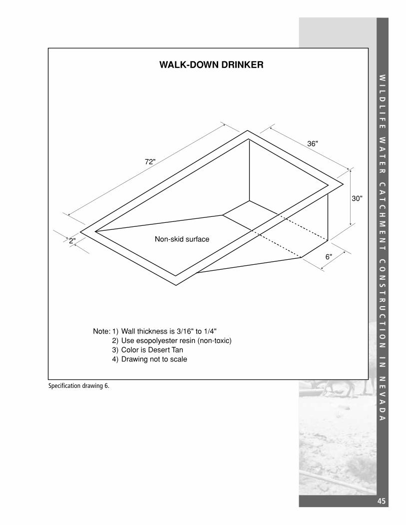
WI
LD
LI
FE
W
AT
ER
C
AT
CH
ME
NT
C
ON
ST
RU
CT
IO
N
IN
N
EV
AD
A
45
Specification drawing 6.
72"
36"
30"
2"
6"
WALK-DOWN DRINKER
Note: 1) Wall thickness is 3/16" to 1/4" 2) Use esopolyester resin (non-toxic) 3) Color is Desert Tan 4) Drawing not to scale
Non-skid surface


WI
LD
LI
FE
W
AT
ER
C
AT
CH
ME
NT
C
ON
ST
RU
CT
IO
N
IN
N
EV
AD
A
47
Chapter 3-SouthernNevada WaterCatchment GuidelinesSlickrock andHypalon GuzzlersThe current emphasis in southernNevada is on “slickrock” collectionsurfaces feeding storage tanks anddrinkers, or artificial aprons (hypalon)placed at ground level (Also seeAppendix A). A slickrock or hypalonunit consists of the apron (collectionsurface), which drains to a dam orsump (collection point), from whichwater is piped to tanks. The tanks storewater for use at a float-valve operatedor self-leveling drinker.
Flexibility in the design, materialsused, and construction are a necessity.Too often, a certain type of waterdevelopment is forced into an inappro-priate location and fails. Projectsshould be adapted to each site. Forexample, we try to use slickrock whenit is available, but sometimes otherconsiderations determine the projectlocation. After evaluating the slickrocksurfaces in the area, it is sometimesdetermined that there are not anyadequate slickrocks in the desired dis-tribution. In such cases, an artificialcollection surface or apron is utilized.This apron option can be a necessitywhen construction and maintenanceefforts negate the use of a slickrocksite.
This chapter covers site selection con-siderations, descriptions of the slick-rock and hypalon collection surfaces,all aspects of the construction process,and observations throughout on theproblems encountered during the plan-ning and construction stages. Thoughthe options and trade-offs involved inproject site selection and constructionmay sometimes appear contradictory,the water development process is oftena series of compromises to fit varyingsituations.
Site SelectionWater catchments should be located inthe best possible habitat for the targetspecies. For example, desert bighornsheep depend heavily upon their visionfor protection; they prefer open waterholes. Locating the drinker near brushor even too close to the tanks mayprovide cover for predators. Likewise,projects built in totally flat terrainnegate the bighorn’s ability to use cliffsand ledges defensively. Placing a projectin or adjacent to precipitous escapeterrain enhances the attractiveness ofthe unit to bighorn. The special traitsor behavioral quirks or each speciesshould always be considered.
The seasonal distributions and usepatterns of the different sexes are very

WI
LD
LI
FE
W
AT
ER
C
AT
CH
ME
NT
C
ON
ST
RU
CT
IO
N
IN
N
EV
AD
A
48
important. If water is placed in an areautilized exclusively by rams, do notexpect to make a real impact on desertsheep in the area. The breeding seasonstarts mid to late summer. During halfthe summer, the rams will not be inthe habitat the ewes prefer. And, toexpand the population, you have tokey in on the ewes.
Total water needs are very important.Bighorns need 1 gallon of water peranimal per day for each day of 100˚ F.Water catchments should be able tomaintain at least 50 bighorns per unit,with additional storage for times ofdrought. Experience has shown that astorage capacity of 6,500 to 7,000 gal-lons per unit is usually adequate. Someof the earlier units ranged in capacityfrom between 3,200 to 50,000 gallons.
Spacing is very important. Bighornsseldom range more than 2 miles fromwater in mid-summer. In southernNevada, units should be clustered inpairs or triads between 1 1/2 to 2 milesapart, with the clusters no more than5 to 6 miles apart. The units shouldnot be visible from existing roads, butcan be placed close enough so thatwater can be pumped to them in casethey dry out.
Anticipated use by all wildlife shouldbe considered when selecting a sitefor the water development. Projectslocated at the range overlap betweenbighorns and deer habitat should takeinto account the higher waterrequirement of the deer.
Collection Surfaces
SlickrockSlickrock is named for its bare-rockcollection surface. This term mostproperly describes the vast, smoothsandstone canyons of Utah. Sincesandstone formations are uncommonthroughout much of Nevada, theharder limestone and volcanic rockformations are used for slickrock devel-opments. You can usually find thelarger surfaces in limestone and thusit is the commonly used surface. Theright drainage in volcanic rock whenavailable, however, can be superb. Thesurrounding soils can absorb water andrelease it slowly over several days.
Drainages are often scoured smoothby eons of sediment-laden runoff.Mountainside drainages are most oftenused. A sloping rock sheet can beexploited, but there is usually a problemfinding a collection point (dam site).
When selecting slickrock, look forevidence of good flows down thedrainage. Persistent cutting along thesides can be an indicator. Rock surfacespolished smooth by water, sand, andgravel can indicate a good drainage.However, many of these sites haveresulted from eons of scouring andonly collect adequate water duringintense storms. Black streaking (algae)in the wash bottom indicates a surfacethat runs or sweeps water for longperiods after rainfall. The ideal way toevaluate the potential of slickrock is tobe at the site during or just after a rain.
Many of the rock surfaces are lacedwith cracks. This isn’t always bad.

WI
LD
LI
FE
W
AT
ER
C
AT
CH
ME
NT
C
ON
ST
RU
CT
IO
N
IN
N
EV
AD
A
49
Where there is fracturing, drainageworks best when the upper surfaces orslabs overlap the lower sections, muchlike roof shingles.
When cracks run lengthwise down thedrainage, they can drain the flow, par-ticularly behind the dam. At the BigDevil and Tungsten Projects, the angleof cracks slowed and drained therunoff. The fracturing of the rocks ranvertical or against the direction of flow.At every point, the water was slowedby a lip of rock; it dissipated into thecracks. The surface can be sealed, butcosts are usually prohibitive if theentire slickrock needs sealing.
The surface slope is important on allslickrocks. Steep slopes get the waterto the dam quicker. This may not bedesired with a low dam as water will belost over the dam. However, you willneed a good slope to capture the lightrains, which a flatter surface mayabsorb.
If the slope is around 30˚ or greater,the water gets to the dam quickly,moving over the cracks with less loss.This can be counted on only withmoderate to heavy rains. The bulk ofthe Mojave rains are light and will belost to the cracks.
Slickrock projects need as large a col-lection surface as possible. An entiremountainside drainage would workbest in the right conditions. Yet, mainwashes are usually avoided. While theyare subject to flooding (good), theyoften have high debris loads (bad).Debris can clog a dam and reduce thevolume of short duration water storage.Main washes rarely have solid bottomsto construct a dam upon. For slickrocks,secondary washes are preferred.
Try to utilize slickrocks with a minimumof 15,000 square feet of surface area(about 1/3 acre). This collection sur-face should fill a 6,900 gallon projecton 3/4 inches of rainfall.
Select the smallest, most efficient damsite possible. It is easier to work withsingle width 4-foot x 8-foot sheets ofplywood and you save on costs (materialsand helicopter time/sling loads).
When locating a site for the dam,consider the volume of water than canbe stored behind the dam. Suddenthunderstorms are a great opportunityto collect water. Almost any dam willfill more quickly than the screenedpipes can siphon off the water. At somepoint, you will lose water over the dam.Allow for storage capacity and you cancollect several hundred to a thousandmore gallons of water.
Development sites are generally selectedin the middle to upper elevations. Thefurther up the drainage the dam isplaced, the less debris should gather inthe runoff. So the need for vast collec-tion areas must be weighed against thedrainage’s potential loads of trash. Ifthe drainage carries much rock, sand,gravel and vegetative debris, you mayhave to occasionally shovel a lot ofjunk from behind the dam. As a coun-terpoint to creating storage capacitybehind the dam, don’t build the damto hold any more debris than you wantto clean out. Gabions (rock-filled wirebaskets) can be built above the dam tohold up debris, but these are onlyeffective if they are cleaned out regularly.Even clean rock surfaces with extensivedebris (i.e., dirt, rocks, leaves), abovethe dam could be a problem. Animalsusing the project will create trailing,which could loosen debris.
Helpful HintUsing the middle to upperelevations in bighorn habitat is usually sufficientto deter use by feral ordomestic livestock.

WI
LD
LI
FE
W
AT
ER
C
AT
CH
ME
NT
C
ON
ST
RU
CT
IO
N
IN
N
EV
AD
A
50
Ideally, the slickrock should have aclean (bare rock) surface. Drainagewith dirt and sand bottoms can absorbwater and hide cracks that could drainwater before it reaches the dam.Brushy vegetation usually requiresextensive, deep root systems and mayalso indicate the presence of cracks inwash bottoms.
The biggest advantage of slickrockprojects is the lower cost. Slickrockdam material costs are one tenth thecost of a hypalon apron. While theapron project requires fewer sling loads(2 to 10), factoring in helicopterexpenses raises the cost of slickrock toslightly less than half that of hypalon.Personnel requirements are roughly thesame for both projects.
Low maintenance, potentially hugecollection surfaces, and apron replace-ment costs are important factors inselecting slickrock. Slickrock collectionsurfaces are natural. Dams are general-ly small. They are aesthetically the bestalternative to natural water sources.
Slickrock surfaces are not as efficient inlight rains as man-made aprons. Therock will absorb some water before itsheds the runoff. You can compensateby using much larger slickrock sur-faces, collecting more during the sub-stantial rains.
Small game slickrock projects shouldalso be strongly considered. While itwould be critical to protect the tops ofthe tanks from larger animals, thecompactness and unobtrusiveness lendsitself well to this application. Small,low elevation slickrocks seem to bemore prevalent especially when you arelooking for large surfaces in the upperelevations.
Tarp ApronsIt is easier to find a good project sitefor a tarp apron than to locate a slick-rock project. On a one-to-one basis,plasticized or rubberized tarps aremuch more efficient at water collectionthan natural surfaces.
Tarp aprons are usually conspicuousunless they are placed in a bowl orwithin a canyon. Their sharp outlineis sometimes distracting. Sunlightreflection is a problem, especially inwilderness or wilderness study areas.
Aging processes also reduce the life oftarp aprons. Weakening occurs morerapidly around edges and damagedplaces in the material. More mainte-nance is required for tarps than slick-rock or metal aprons, but repairs areoften simple.
The preferred apron material in south-ern Nevada is hypalon. The materialconsists of rubberized mat layers rein-forced by a nylon webbing. The moresuitable thickness for our uses are the.45 mil and .60 mil.
Hypalon lays flat on the ground and isflexible. It can be cut and glued to fitaround obstacles. Customizing theshape of the apron increases the timeand effort; therefore it is rarely done.
The cost of a hypalon collection area isroughly twice the cost of a dam. Whilethe hypalon is a more efficient surface,it is usually limited in size by cost andthe availability of an adequate site andworkforce.
The hypalon length and width can bevaried according to need. It is often,but not always, available in variouscolors: black, white, tan, and gray.
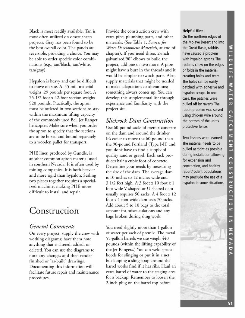
WI
LD
LI
FE
W
AT
ER
C
AT
CH
ME
NT
C
ON
ST
RU
CT
IO
N
IN
N
EV
AD
A
51
Black is most readily available. Tan ismost often utilized on desert sheepprojects. Gray has been found to bethe best overall color. The panels arereversible, providing a choice. You maybe able to order specific color combi-nations (e.g., tan/black, tan/white,tan/gray).
Hypalon is heavy and can be difficultto move on site. A .45 mil. materialweighs .29 pounds per square foot. A75-1/2 foot x 42-foot section weighs920 pounds. Practically, the apronmust be ordered in two sections to staywithin the maximum lifting capacityof the commonly used Bell Jet Rangerhelicopter. Make sure when you orderthe apron to specify that the sectionsare to be boxed and bound separatelyto a wooden pallet for transport.
PHE liner, produced by Gundle, isanother common apron material usedin southern Nevada. It is often used bymining companies. It is both heavierand more rigid than hypalon. Sealingtwo pieces together requires a special-ized machine, making PHE more difficult to install and repair.
Construction
General CommentsOn every project, supply the crew withworking diagrams; have them noteanything that is altered, added, ordeleted. You can use the diagrams tonote any changes and then renderfinished or “as-built” drawings.Documenting this information willfacilitate future repair and maintenanceprocedures.
Provide the construction crew withextra pipe, plumbing parts, and othermaterials. (See Table 1, Sources forWater Development Materials, at end ofchapter). If you need three, 2-inchgalvanized 90˚ elbows to build theproject, add one or two more. A pipemight have a burr in the threads and itwould be simpler to switch parts. Also,supply materials that might be neededto make adaptations or alterations;something always comes up. You candevelop this supplemental list throughexperience and familiarity with theproject site.
Slickrock Dam ConstructionUse 60-pound sacks of premix concreteon the dam and around the drinker.It’s easier to move the 60-pound thanthe 90-pound Portland (Type I-II) andyou don’t have to find a supply ofquality sand or gravel. Each sack pro-duces half a cubic foot of concrete.Determine your needs by measuringthe size of the dam. The average damis 10 inches to 12 inches wide and 3 1/2 feet high. A 3 foot x 10 foot x 1foot wide V-shaped or U-shaped damusually requires 50 sacks. A 4 foot x 12foot x 1 foot wide dam uses 70 sacks.Add about 5 to 10 bags to the totalaccount for miscalculations and anybags broken during sling work.
You need slightly more than 1 gallonof water per sack of premix. The metal55-gallon barrels we use weigh 440pounds (within the lifting capability ofthe Jet Rangers.) You can weld specialhoods for slinging or put it in a net,but looping a sling strap around thebarrel works find if it has ribs. Haul anextra barrel of water to the staging areafor a backup. Remember to loosen the2-inch plug on the barrel top before
Helpful HintOn the northern edges ofthe Mojave Desert and intothe Great Basin, rabbitshave caused a problemwith hypalon aprons. Therodents chew on the edgesor folds in the material,creating holes and tears.The holes can be easilypatched with adhesive andhypalon scraps. In onecase, the patches werepulled off by ravens. Therabbit problem was solvedusing chicken wire aroundthe bottom of the unit’sprotective fence.
Two lessons were learned:The material needs to bepulled as tight as possibleduring installation allowingfor expansion and contraction, and healthyrabbit/rodent populationsmay preclude the use of ahypalon in some situations.

WI
LD
LI
FE
W
AT
ER
C
AT
CH
ME
NT
C
ON
ST
RU
CT
IO
N
IN
N
EV
AD
A
52
using the 3/4-inch spigot. If you donot allow air to displace the drainingwater, the vacuum will slowly collapsethe barrel.
We use a 1/3-yard electric mixer with agas-powered engine. It is easily slungand can be moved over uneven groundby four people at the site by tying a 2by 4 to either side. Sling the mixer to aspot near the dam. You can rarely pourfrom the mixer into the dam forms.Pour the cement into 5-gallon buckets,then pour into the forms. Set thewater above the cement and mixerusing a 50- or 100-foot garden hose toget water to the mixing site. Just incase, have an extra 5 to 10, 5-gallonbuckets for hauling water, rocks, andsand.
Any dirt and brush at the dam siteshould be cleared to make sure thebottom is solid. Arizona uses a sealantto seal the dam and create tinajas (SeeAppendix B, Lasting Waters for Bighornby Robert S. Gray).
One inch and 1/2-inch steel reinforc-ing bar (rebar) is installed in the rockin holes drilled with a roto-hammer.(The Milwaukee brand roto-hammerneeds at least a 1200 watt generator).Rebar can be bought in lengths of upto 20 feet cut to your specifications.Rebar loads should be wrapped tightlywhen slung. Two equal length strapsare wrapped around opposite ends ofthe longer lengths of rebar. Bundles ofthe shorter length rebar are tie-wiredto the longer lengths near the ends.Place at least one sling strap over thesmaller bundles to keep them in place.
Anchor the rebar in solid rock. One,1-inch rebar is set horizontally, an inchfrom the top of the dam. Another
1-inch horizontal can be placed belowthat. One-inch uprights are spacedevery 2 to 3 feet from the middle and1/2-inch rebar is spaced every 12 inches.Order lengths accordingly, but if a few1/2-inch pieces are slightly long, theycan be bent to fit.
The dam is formed with plywoodsheets, 1/2-or 5/8-inch x 4-feet x 8-feet(Figure 1). Five-ply is stronger thanthree-ply. The plywood is scribed alongthe bottom edge to fit the contour ofthe wash bottom. To do this, hold theplywood up to the top level of thedam. Using a tape measure, measurethe height of the dam straight up frompoints along the bottom, 4 to 6 inchesapart. For example, if the dam will be3 feet high, the plywood is held 3 feetabove the lowest point. Then the ply-wood is marked 3 feet straight aboveeach point. A small chain saw or sabresaw is used to cut the plywood.
Cut two 2-inch slots in the plywood5 to 12 inches apart and up 4 to 5inches from the lowest point. Line theslots up on each form. These are forthe galvanized pipe that runs throughthe dam. You can use a 2 3/8-inch holesaw to cut the holes for the pipe, but itmakes stripping the forms very difficult.It is easier to cut slots and use plywoodscraps and wood screws to block theslot below the pipes. When both ply-wood forms are cut, put them in placeabout a foot apart. Using a 3/8-inch x12-inch drill bit, drill holes throughboth forms. The face of one plywoodsheet needs six to eight evenly spacedholes. Try to locate holes so that thebit passes close to the upright rebar.
Insert the 1/4-inch x 14-inch allthreadpieces. There should be a nut holdinga 1/4-inch x 1 1/2 inch fender washed
At the Jerry (Hughes)Project in the MuddyMountains, there was noroom to set the mixerdown near the dam. Asheet metal tube was madefor the project. Cementwas poured into a funnel,down the tube, and intothe dam form.
At the Patches Projectin the Spotted Range,the mixer could only beplaced at the bottom of adry falls, 35 feet below thedam. The crew formed abucket brigade to get thecement to the dam. Forsafety, a rope was attachedto each bucket and washauled in by the dam crew.If someone lost their grip,the dam crew would keepit from falling on anyonebelow. The rope alsoallowed the dam crew tolower the buckets directlyto the mixer.

WI
LD
LI
FE
W
AT
ER
C
AT
CH
ME
NT
C
ON
ST
RU
CT
IO
N
IN
N
EV
AD
A
53
against each of the interior faces.(Figure 2). A nut and fender washer onthe outside holds the plywood 8 to 10inches apart. A 4-foot x 8-foot damwould require six to eight allthreadassemblies to separate the forms. Usetie wire to tie the allthread to the rebar.
The allthread assembly works well onsmall structures. If you are familiarwith heavier construction techniques,using snap-ties and shoes is impracticalbecause of the expense and weight. Ifyou have to wait for the dam to setand then hike to the site to haul theshoes out, you’ll only do it once (SeeAppendix B).
Insert the two 2-inch x 30-inch galva-nized, male-threaded pipes through the
slots at the bottom. Attach theJohnson filtration screens to theupstream side of the pipes. Attach thePVC (Driscopipe) pipe to the down-stream ends of the pipes with couplersand barb adapters. If you anticipatehigh debris loads, you might want touse a 90˚ elbow to angle the screenstraight up. This screen should collectwell enough as debris rises behind thedam.
When the screens are set, wire thepipes to the rebar in the dam. Makesure the screens themselves are notwedged against the rocks or each other.(You may need to remove them atsome later date.) Put a small rock orwood under the screens to hold themoff of the bottom.
Figure 1. Dam design and materials.

WI
LD
LI
FE
W
AT
ER
C
AT
CH
ME
NT
C
ON
ST
RU
CT
IO
N
IN
N
EV
AD
A
54
Figure 2. Allthread assembly.
Put rocks into the form to take upspace and stretch the cement supply.Do not forget to mix in mortar dye tosimulate the color of the surroundingrock. You can also inlay the face of thedam with rocks to make it blend inwith the surroundings. Usually, theforms are tapped with a hammer tovibrate out air pockets that might leaveweak spots. Do not pound the down-stream side of the dam that you facedwith rocks, or the rocks will sink backinto the cement. Gather the cementbags off to the side or above the damand weight the pile with rocks.
If you use excess cement to fill inbehind the dam, protect the screensand don’t let the cement wedge thescreens in place. It is best to have thescreens sit in a slight depression. Try topour cement against the plywood or itwill be hard to remove the form. Youwill need a wood chisel and hammerto break it loose. Surplus cement canalso be used to create a curb whichdirects more runoff behind the dam.
To remove the forms, bring along a7/16-inch combo wrench, crowbar,and vicegrips. Back the nuts on theoutside of the forms off about a 1/4-inch. Clamp the vice grips onto theallthread and wiggle it up and down
until it breaks off next to the form. Prythe form away from the dam. Anyallthread that sticks out should behammered down. Save the 1/4-inchnuts and fender washers. You can usethem many times over.
Hypalon Apron ConstructionThe aprons for the standard desertbighorn sheep projects (6,900 gallonstorage capacity) are purchased in twosections for weight and handling con-siderations as noted earlier. Around theyard, you can load the pallets with aforklift or four strong people. In thefield, the pallets can be unloaded fromtruck or trailer by one person with adigging bar. If you load the trailer rightand have something to tie-off to, youcan drive out from under the load. Evenif this breaks the bands around thebox, the sling straps will hold the loadtogether when you sling it to the site.
The 37 3/4-foot x 40-foot panels donot translate to a 75 1/2-foot x 40-footcollection surface. The pieces are over-lapped by 1 to 2 feet and the perimeterberms eat up more material. The fin-ished product averages 65 feet x 35feet or 2,275 square feet of effectivesurface (15 percent of the target surfacearea for a slickrock). This translates to1,417.3 gallons of water per inch of
Helpful HintOccasionally, the screensare set too high. In somecases, up to 100 gallonsmust collect behind thedam before it startsthrough the screens. Youcan take up space belowthe screens by filling in withrocks. This will displacesome of the “wasted”water. Creative cementwork is most helpful incorrecting this problem.

WI
LD
LI
FE
W
AT
ER
C
AT
CH
ME
NT
C
ON
ST
RU
CT
IO
N
IN
N
EV
AD
A
55
rain. An apron this size requires 4.86inches of precipitation to fill a 6,900gallon project.
Locate the apron on a relatively flatarea. You need some slope, but themore the surface is tilted, the lesshorizontal exposure you have. Thereshould be few rocks on the apron siteitself, but you will need a supply oflarge rocks to place on the apron at theend of the installation. Rocks found onthe apron site must be removed, bro-ken, or covered with dirt to preventthem from puncturing the material.
Lay out the apron area so that thelowest point or corner is closest to thetanks. You can place the low pointanywhere along the edge, but the cor-ners are the most convenient. Clear a60 foot x 30 foot area. Pull rocks anddirt downhill to create the lower bermsor “V” where the water will be collected(Figure 3). The collection cornershould be more rounded than theothers. The low point and berms willtake up more material to cover the lowpoint and berms pulling in hypalonfrom the corner.
Form a well or basin at the collectionpoint; the berm should be at least 2 feetabove the lowest apron point. You willneed some storage capacity for theintense showers. The greater the slopeof the apron, the larger the well must be.
Pull out one apron section and lay it inplace on the lower end, making surethat the well and berm are covered.Make any adjustments. Set the secondsection out with 12 to 18 inches ofoverlap, uphill over downhill.
With the downhill berms set and cov-ered, the crew can now lay the uphillapron edges back and clear any more
Bare #1Despite 3 years of goodrainfall, Bare #1 has notfilled. The steep slopereduces the horizontal surface area. The slope alsoprevented a large well frombeing built. The intensestorms overfill the welland much water is lost.
brush, making low berms for the uphillsides. If your apron is on a hillside, youmay want to cut drainage trenches tokeep runoff from cutting your apron.
When projects are built in the winter,never sling the hypalon adhesive to theproject site ahead of time. Cold adhe-sive is hard to work with. It is aboutthe same as spreading cold tar. Keep itwarm until it goes up to the projectsite and keep it as warm as possibleuntil you need it. You can use a heatgun or blowdryer to warm the closedcan. Never use a flame because of theflammable nature of the adhesive.
Always check the adhesive before theproject, regardless of when the canarrived from the manufacturer. If thetemperature is warm and the adhesiveis still thick, the trichloroethylene(TCE) has evaporated. You can addTCE, which happens to be thehypalon solvent you use. Do not“water” the adhesive down too much;it has to stay where you brush it onand you don’t want it to take forever todry. Be careful, TCE is classified as ahazardous chemical.
While the berms are being finished,start gluing the apron pieces together.Clean the surfaces to be glued with arag and hypalon solvent. The solventremoves a protective film and yields aproper surface for bonding. Start in themiddle of the seam and work outward.This helps keep the seam flat and even.
Work slow to get a good, sealed seam.Apply the adhesive in only 12- to 18-inch sections at a time (varies withtemperature) or the adhesive will drytoo fast. Apply the adhesive with a 4-inch paintbrush. Use a linoleumroller to press the pieces together andto work out any air pockets or bumps.

WI
LD
LI
FE
W
AT
ER
C
AT
CH
ME
NT
C
ON
ST
RU
CT
IO
N
IN
N
EV
AD
A
56
It can help to put a flat surface underthe section you are working on; youcan use the cardboard from the apronsections packaging.
After the seam is completed, pull thematerials as tight as possible. Makesure it doesn’t catch on a rock. Trencharound the outside of the berms andlay the edges in the furrow. After thegluing and pipe fitting are finished, userocks and dirt to bury the apron edges.
At the collection well, pull the apronback over the berm. Bring the two 2-inch polypipes through the berm atthe lowest location. The pipe should
come through the material just abovethe lowest point of the apron or theJohnson filtration screens will stick upat odd angles. You could get them tolay flat with a 2-inch, 45˚ or 90˚elbow. Try to keep at least one screenflat and straight. This allows for thegreatest flow down the pipe anddecreases the chance of any backup.Mark the apron material 2 to 4 inchesabove the lowest point and cut twocircles or “Xs” in the apron material atleast 1 foot apart. The spacing allowsroom for the hypalon pipe boots to beinstalled. Pull the pipes through thematerial and lay the apron over theberm.
Figure 3. Badger apron water development; example of a hypalon apron setup.

WI
LD
LI
FE
W
AT
ER
C
AT
CH
ME
NT
C
ON
ST
RU
CT
IO
N
IN
N
EV
AD
A
57
A 2-inch, 90˚ hypalon pipe boot fitsover each pipe like a sleeve with asquare base that is glued to the apron.Slide the boot on, then attach thegalvanized barb adapter and Johnsonscreens to the pipe. Use a tube of sili-cone caulk to form a plug or gasketaround the pipe on both sides of theapron material. If the boot comesunglued or leaks, the plug will stop orretard water from steeping out here.Do not try to use silicone caulk asadhesive; it is not designed for this use.Glue the boot base to the apron andclamp the boot sleeve around the pipewith two #36 or #40 hose clamps. Becareful not to heat the pipe bootsleeve; it will melt.
Put rocks on the apron to keep thewind from pulling the apron and tobreak up the solid color. Try to coverthe whole apron.
Some tarp-type aprons utilize a metalsump box to collect the water. Theseboxes have a number of problems; theybecome rusty and messy over time, thesump is hard to mate with the apronmaterial, water is lost when the sumpoverfills, and there is a problem if theoverflow erodes the berm. To helpwith this problem at Big Bertha, theFraternity of the Desert Bighornorganization made a hypalon liner forthe sump box. The box was also largeenough to hold two filtration screens.Water quality is as important as quantity.
General PlumbingThe need for standardization ofplumbing must be emphasized or youcan end up with some real repairnightmares. For example, a manifoldthat starts with a 1-inch tank adapter,goes to a 3/4-inch gate valve, then to a1 1/4-inch drinker line, and finisheswith a 1/2-inch float valve. If a projectneeds repairs you should not have totake an assortment of plumbing partsin various sizes up and down themountain.
We use 1-inch and 2-inch parts(Figures 4 and 5). Our hose clampshave a slotted, #10 hex head. To main-tain consistency, the insulation sheetmetal screws also have a #10 hex head.A 5/16-inch nutdriver fits the #10 size.
At every pipe connection, we useteflon tape and a slow-dry pipe com-pound; both help ensure a better fitand seal. If you have to remove partslater, these will make it a much easiertask as they inhibit rusting. We caneven use it on the Johnson screenreducers. At the top of the plumbingsystem are the “Johnson” filtrationscreens. They are stainless steal wellpick-up screens, and are designed tofilter out sand and debris at the bot-tom of domestic water wells. Thescreens are designed to filter up to 30 gallons per minute.
The unit is 4 inches in diameter and24 inches long with female threads onone end and a plate welded to theother. A 2- to 4-inch galvanized busingis used to reduce down to 2-inch pipe.
Helpful HintBuy the highest quality,heavy duty plumbing you can afford. Use theminimum number of connections; every fittingis a weak point. Reducethe chances for failure bykeeping the plumbing assimple and as strong aspossible.

WI
LD
LI
FE
W
AT
ER
C
AT
CH
ME
NT
C
ON
ST
RU
CT
IO
N
IN
N
EV
AD
A
58
Figure 4. Water development, 1-inch plumbing.

WI
LD
LI
FE
W
AT
ER
C
AT
CH
ME
NT
C
ON
ST
RU
CT
IO
N
IN
N
EV
AD
A
59
Figure 5. Water development, 2-inch plumbing.

WI
LD
LI
FE
W
AT
ER
C
AT
CH
ME
NT
C
ON
ST
RU
CT
IO
N
IN
N
EV
AD
A
60
There are hundreds of thin slots alongthe screen that allow water throughand keep all but the finest silts out ofthe system. The slots are .05 mm inwidth.
The screens can be productive whenfully covered with sand, rocks, andgravel; they are designed to be con-stantly immersed, as in a well shaft.However, the effectiveness of thescreens is significantly reduced whenvegetative debris is sucked onto thesurface. This problem usually happensright after construction as the brushclearing creates a mess that is washeddown in the first few rains. Alwaysclean the screens during maintenanceand remove any debris found behindthe dam.
PVC was heavily used in the waterdevelopments at one time. But, PVCis made to be buried or protected insome other manner. In direct sunlight,PVC plastic oxidizes and deteriorates;it freezes and cracks easily after only ayear of exposure. Even when buried, itcannot take the stress. PVC has beendisplaced by galvanized plumbing andstainless steel tank adapters. Wheneverwe get the chance, we upgrade.
Only the first few Nevada Division ofWildlife (NDOW) projects utilizedsolid galvanized manifolds, which carrywater from the tanks to the drinker.Polypipe is now used on the 1- and 2-inch pipelines. The pipe is Drisco8600 by Phillips Petroleum. It is madefor exterior, industrial applications andis produced with a strong ultravioletinhibitor. Drisco is available in variousPSI ratings, but we usually use the 160PSI in 1-inch pipes, and the 110 PSIin 2-inch pipes. The pipe is flexible
and expands and contracts dependingupon the conditions. When usingpolypipe, always allow for some pipemovement. We do most of our con-struction in the winter and spring sothe pipe is already contracted.
In northern parts of the state (otherthan the BLM Carson City District),there was a problem with polypipebecause it popped off the fittings.Frozen water in the pipes was suspect-ed of forcing the pipe off; it is morelikely that the pipe was installed in thesummer when it was fully expanded inthe heat. When water did freeze in thesystem, the pipe contracted off of thefittings.
Part of the beauty of Driscopipe is its flexibility. It should be allowed toexpand and contract. Even whenburied, polypipe should be installedwith a good amount of slack. The 2-inch pipelines can be run 450 feetfrom dam to tanks and can contract 1 to 3 feet along its length.
The polypipe is fitted on to galvanizedplumbing by heating the pipe. A pipewelding machine can fuse pipe sectionstogether, but it is not well adapted toremote construction. We use smallpropane torches to heat the pipedirectly and slip it onto the fitting.When the clamps are in place, the pipeis heated again and the clamps arequickly tightened.
Note: Phillips Petroleum has expressedsome concern about heating with a directflame. They are unsure as to whether aflame will harm the UV inhibitors.However, there has been no evidence ofany problems with this technique.
TroubleshootingAfter watching one dam fillup during a sudden thun-derstorm, it was surprisingto find only a trickle goinginto the tanks. The suctionhad pulled vegetationtightly onto the screens,allowing little waterthrough. After scrapingthe screens by hand, the1,700 gallons behind thedam drained in 20 minutes.

WI
LD
LI
FE
W
AT
ER
C
AT
CH
ME
NT
C
ON
ST
RU
CT
IO
N
IN
N
EV
AD
A
61
PipelineThe pipe from the dam to the tanks isusually 2-inch Driscopipe 8600; the110 PSI rating is preferred. HigherPSI ratings mean thicker pipe wallsand smaller inside diameters. Standardsplumbing barbed adapters suit thesewell. Any tighter inside diameter (160 or 190 PSI) pipe can be almostimpossible to slip on adapter plumbing.You have to use a file or rotary rasp totrim the interior. The heavy duty pipesare also just that, heavier.
In the winter, place the pipe in the sunto warm it up; it will roll out easier ifit is warm. Use two to four people toroll the pipe out; don’t uncoil it. Itcan cramp and will be very hard tostraighten out. Cut the bands on thepipe roll before you get to them. If youover-rotate the roll, the weight of thepipe will crimp it. You may need tocut that point and insert a galvanizedbarb-x-barb adapter to keep it fromrestricting flow or being a weak pointover time. Use two #36 hose clampson each side of the barb. When neces-sary, use light heat to bend the pipe tofit it into crevasses or to go aroundcorners.
Make as straight a run to the tanks aspossible; but, when you lay the pipeduring the summer, allow for contrac-tion of the pipe in the winter. In otherwords, don’t pull it too tight.
Long runs of pipe may be subject tovaporlocking especially if there is notmuch fall. Get advice from an engineerabout venting long pipelines.
We recommend that there be at least10 feet of drop between the bottom ofthe dam and the top of the tanks. Tryfor a quick drop of 5 feet after the pipe
leaves the dam; this creates a suctionwhen there is sufficient water behindthe dam and creates a good flow downthe pipeline. It gets water to the tanksfaster, which is important in a cloud-burst rain.
The pipeline should be painted andburied, if possible. Paint and cover thepipe with rocks where the ground istoo rocky. Protecting any componentof the project from exposure willextend the life of the project.
To keep the pipelines out of wash bot-toms, the pipe is often hung along thewash walls with pipe clamps or pipehanger. Try not to hold the pipe rigidlyat any point (expansion and contrac-tion again). The 5-inch pipe hangersare preferred because they allow thepipe to move and support both pipes;2-inch pipe clamps hold things toorigidly.
Because of the weight of the pipe andthe force of the water going throughthe pipe, there is a lot of jerking andtwisting. Regular lead masonry anchorseventually loosen. Expansion anchorsare better. Chemical anchors are betteryet. A glass vial within a vial is placedin the hole. The anchor bolt is jammedin to break the vials and is twisted tomix the epoxy. The bolt is bonded tothe rock.
There is a new epoxy “gun” which usescartridges, more or less like a caulkgun; this appears to work better. Itgoes by the name Epcon and is mar-keted by Ramset/Red Head.
Tank LocationThere should be a minimum drop of5 feet between the bottom of theapron/dam and the top of the tanks.
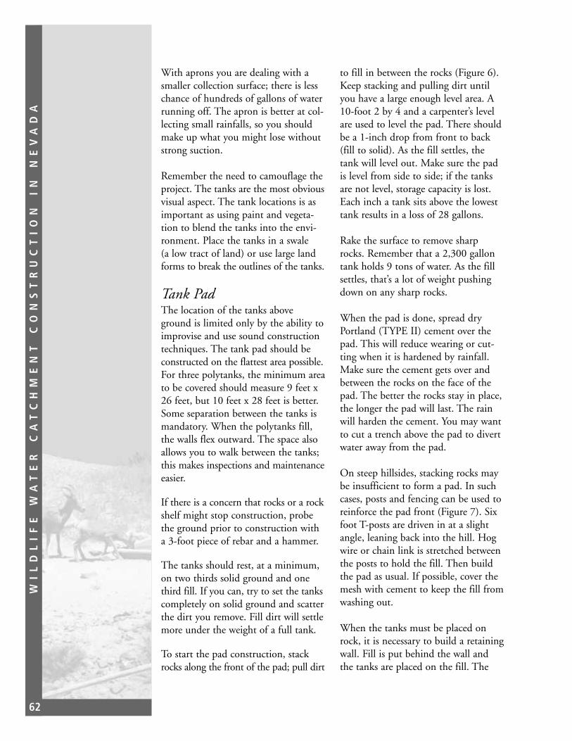
WI
LD
LI
FE
W
AT
ER
C
AT
CH
ME
NT
C
ON
ST
RU
CT
IO
N
IN
N
EV
AD
A
62
With aprons you are dealing with asmaller collection surface; there is lesschance of hundreds of gallons of waterrunning off. The apron is better at col-lecting small rainfalls, so you shouldmake up what you might lose withoutstrong suction.
Remember the need to camouflage theproject. The tanks are the most obviousvisual aspect. The tank locations is asimportant as using paint and vegeta-tion to blend the tanks into the envi-ronment. Place the tanks in a swale (a low tract of land) or use large landforms to break the outlines of the tanks.
Tank PadThe location of the tanks aboveground is limited only by the ability toimprovise and use sound constructiontechniques. The tank pad should beconstructed on the flattest area possible.For three polytanks, the minimum areato be covered should measure 9 feet x26 feet, but 10 feet x 28 feet is better.Some separation between the tanks ismandatory. When the polytanks fill,the walls flex outward. The space alsoallows you to walk between the tanks;this makes inspections and maintenanceeasier.
If there is a concern that rocks or a rockshelf might stop construction, probethe ground prior to construction witha 3-foot piece of rebar and a hammer.
The tanks should rest, at a minimum,on two thirds solid ground and onethird fill. If you can, try to set the tankscompletely on solid ground and scatterthe dirt you remove. Fill dirt will settlemore under the weight of a full tank.
To start the pad construction, stackrocks along the front of the pad; pull dirt
to fill in between the rocks (Figure 6).Keep stacking and pulling dirt untilyou have a large enough level area. A10-foot 2 by 4 and a carpenter’s levelare used to level the pad. There shouldbe a 1-inch drop from front to back(fill to solid). As the fill settles, thetank will level out. Make sure the padis level from side to side; if the tanksare not level, storage capacity is lost.Each inch a tank sits above the lowesttank results in a loss of 28 gallons.
Rake the surface to remove sharprocks. Remember that a 2,300 gallontank holds 9 tons of water. As the fillsettles, that’s a lot of weight pushingdown on any sharp rocks.
When the pad is done, spread dryPortland (TYPE II) cement over thepad. This will reduce wearing or cut-ting when it is hardened by rainfall.Make sure the cement gets over andbetween the rocks on the face of thepad. The better the rocks stay in place,the longer the pad will last. The rainwill harden the cement. You may wantto cut a trench above the pad to divertwater away from the pad.
On steep hillsides, stacking rocks maybe insufficient to form a pad. In suchcases, posts and fencing can be used toreinforce the pad front (Figure 7). Sixfoot T-posts are driven in at a slightangle, leaning back into the hill. Hogwire or chain link is stretched betweenthe posts to hold the fill. Then buildthe pad as usual. If possible, cover themesh with cement to keep the fill fromwashing out.
When the tanks must be placed onrock, it is necessary to build a retainingwall. Fill is put behind the wall andthe tanks are placed on the fill. The

WI
LD
LI
FE
W
AT
ER
C
AT
CH
ME
NT
C
ON
ST
RU
CT
IO
N
IN
N
EV
AD
A
63
same techniques that are used to buildthe dam are used to make the retainingwall. An L-shaped wall 3 1/2 feethigh and 20 feet in overall lengthtakes 100 bags of cement.
Use rocks and sand to fill the voidbehind the wall. Overfill slightly toallow for settling. At the White Basin(Muddy #2) Project (Figure 8), asource of sand was not convenient.We used the helicopter and a simpledump bucket to haul 4 cubic yards
(60 five-gallon buckets) of material atsix buckets per load.
TanksWhat type of tanks should you use?Site selection will have a lot to do withthat. In remote locations with shallowsoils, tanks must remain above theground. Most of the fiberglass tankscome in sections like slices of pie—four tank sections and four lid sec-tions. They are broad and low.
Figure 6. Tank pad profile.

WI
LD
LI
FE
W
AT
ER
C
AT
CH
ME
NT
C
ON
ST
RU
CT
IO
N
IN
N
EV
AD
A
64
Tank 7. Steep tank pad.

WI
LD
LI
FE
W
AT
ER
C
AT
CH
ME
NT
C
ON
ST
RU
CT
IO
N
IN
N
EV
AD
A
65
Figure 8. Muddy #2 tank pad.

WI
LD
LI
FE
W
AT
ER
C
AT
CH
ME
NT
C
ON
ST
RU
CT
IO
N
IN
N
EV
AD
A
66
It is best to paint the tanks before thematerials are hauled out. They will getscratched during construction, but youcan touch them up. Also, install thetank adapters and mark the bottomsaccording to their setup location(North-Middle-South). The alignmentis included in the working diagrams.
Two fiberglass tank types are the para-bolic or saucer tanks and the rangelandstyle tank. The parabolic tanks are of990-gallon capacity and are 16 feetacross and 2.8 feet high in the center.The rangeland style tanks hold 2,100gallons and are 16 feet across and 2.75feet high. The bottom and side seamson the larger tanks total 37.5 linearfeet. We have not been able to get agood seal on these and water rarelystays long in all but two of the elevenNevada applications. In one MojaveDesert BLM project, the fiberglassbegan to deteriorate and water weptthrough the side walls. Yet fiberglasstanks can work well. The Utah Divisionof Wildlife Resources and BLM continueto use these tanks with success.
One project used a big 5,000 galloncorrugated metal cattle tank. The opentop proved to be a problem in theMojave heat at the Arrows #1 project.Evaporation was high, but wind actionwas even worse. The wind actuallycrested waves and sloshed the waterover the sides. We built a lid for thetank to solve the problem.
Another problem was the 5,000 gallondesignation. The tank would hold5,000 gallons if it came with a bottomplate. Instead, the tank had to be sunkin concrete to form a bottom. As aresult, the tank held only 3,810 gallonsand was consistently drank dry untiltwo 1,600 gallon polytanks were added.
We have primarily opted for the poly-ethylene tanks. The standard grade2,300-gallon tanks are light at 450pounds and flexible (See Table 2,Polyethylene Tank Sizes, at the end ofthis chapter). They can be handledroughly with few problems. One ofthe earlier models was dropped from ahelicopter at 150 feet. The caved-insides were pushed out and it hasworked well for 10 years.
The polytanks are manufactured fromtwo resins; cross-linked and linear-low.The cross-linked are molded cross-adhering resins, while the linear-lowdensity resins do not bond as strongly.Most linear-low applications shouldnot be placed in freezing areas; theyare more suited to interior (warehouse)situations.
The standard grade crosslink tanks arefor fluids of 12 1/2 pounds per gallon.The heavy-duty grade tanks are forfluids of 16 pounds per gallon. Thelatter cost more and exceed 500 pounds.
One advantage of these tanks is thatsmall holes are easily repaired. Hotmelt glue and a screw or bolt is all thatis needed.
One problem with polytanks is theycan’t be buried. If they are even partiallyburied and the water level gets low, thedirt can cave in the tank wall. It is notruined, but now it holds less water.This has occurred in northern areaswhere the tanks were buried to keepthe plumbing below the freeze level.
The problem with burying tanks isgetting enough storage capacity under-ground. Even in the best sheep habitat,it is virtually impossible to bury any-thing, much less a large tank. And, if
Helpful HintNever store the polytankson their sides withoutblocking them properly; astrong wind can send themrolling.

WI
LD
LI
FE
W
AT
ER
C
AT
CH
ME
NT
C
ON
ST
RU
CT
IO
N
IN
N
EV
AD
A
67
there is a good site in sheep habitat,you usually cannot get a backhoe to it.
If you do not completely bury thetank, you have to deal with animalswalking on the top. The answer is tofence the tank area. Depending on thelocation, you might have to fence bothtanks and the entire project to excludelivestock.
Polytank Set UpThe standard tank setup faces themanholes in, toward the other tanks.Use ladders placed against the tanks tocheck water levels. Leave an aluminumladder at each site for inspections.
Most holes are drilled with a 2 3/8-inchhole saw. A 2 1/2-inch hole saw willwork, but is not as tight. You can usean adjustable fly-cutter bit, but if youstandardize, you only need two holesizes. The other size is a 1 5/8-inch holesaw for the tank adapter. A 3/8 inchdrill bit is also needed for the tankadapter bolts.
The tank adapters are installed in theyard, which saves time and helps toensure that they are all installed thesame way. We have also abandoned the1-inch PVC adapters for 1-inch stain-less steel tank adapters (Figure 9). Sofar, these units have been problem free.
There are two types of tank adapters.One has a base plate with bolts thatprotrude through the tank wall andsqueeze the tank wall between it andthe outside plate with the 1-inch femalethreaded coupler. The adapter we prefer has the 1-inch female threadedcoupler attached to the base (interior)plate. This unit has a single flat solidsealing face, while the first unit hastwo seals to make. The hole is pluggedwith a 1-inch plug to keep dirt andanimals out prior to construction.
The only other hole drilled at the yardis the equalizer hole near the manholeon each tank for helicopter transport.We place the sling trap and taglinethrough this hole and the manhole.There have been few problems; justmake sure that the strap does not bindon and crack the ring for the tank lidto screw into.
You could also drill holes for the over-flows and attach the plumbing, but itis usually not that difficult to do it onsite. The problem with doing it before-hand is that the plumbing could catchwhen it is rolled around or slung.Remember also, if you drill all your 2 3/8-inch holes in the yard, you donot allow for any fine tuning or unex-pected circumstances. In the end, youmay have to plug holes that do notsuit the situations encountered.
In the yard, lay the polytanks on theirsides to get in and out of them. Theyare easy to roll, but be careful in windysituations.
Be very careful when you work in atank at a remote project alone or in thesummer. The enclosed system gets veryhot and very humid.
Pipeline InflowBring the inflow pipes into the tank ashigh as possible. The inflow pipe holewill remain unsealed, although thepipe will fit very snugly. If you placethe hole too low, water will seep outand bring the tanks to that level. TheBLM has two 1,600-gallon tanks inthe Bird Spring Range at a horsewater development that are effectively800 gallon tanks. The inflows weredrilled halfway up. The simple siliconesealer is moved by the contraction ofthe filter pipe.
Helpful HintTie a 5-gallon bucket to arope for anyone going intothe tank. They can stand onthe bucket to get out; therope is then used to pullthe bucket back out.

WI
LD
LI
FE
W
AT
ER
C
AT
CH
ME
NT
C
ON
ST
RU
CT
IO
N
IN
N
EV
AD
A
68
Figure 9. Stainless Steel tank adapters, 1-inch plumbing.

WI
LD
LI
FE
W
AT
ER
C
AT
CH
ME
NT
C
ON
ST
RU
CT
IO
N
IN
N
EV
AD
A
69
Shove 8 to 10 feet of the inflow pipeinto the tank. The pipe will expand andcontract, but it will eventually settle.If there is a possibility of the pipe pullingout, attach a #36 hose clamp onto theend of the pipe in the tank. If youused the 2 3/8-inch hole saw, the pipewill not pull out past this point.
The pipeline should not be attachedtoo rigidly to the tank; flexing of thepipe with temperature changes will putundue stress on the tank wall.
One screen will always be lower than theother, so one pipeline will fill quickerthan the other. This may be valuableto know. In light rains, this pipelinewill take all the water. If the main tankis the only one on and you aren’t goingto be able to get to it to change tanksduring the use period, you’ll want allthe recharge to go into that tank.
EqualizersEqualizers are pipe attachments thatconnect the tanks and allow excess waterto flow from an almost full tank intoanother tank. Equalizers are a backup.When you have two pipelines in athree-tank setup, or when one pipelinefails, you need a backup fill method.
You can equalize between the tanksthrough the manifold plumbing.However, this plumbing is usuallysmaller and is not capable of equalizingquickly. When the water is flowing,you have to make every reasonableeffort to collect it. Keeping all tanks onto equalize also reduces the ability toswitch tanks on and off, maintaining areserve water supply. The equalizersshould be kept high. The tanks squatwhen full and pressure on the tankwalls by the equalizers varies. Thisshifting causes many equalizers to leakat one tank or the other. Placing the
equalizers too low could easily reduceyour storage capacity if they leak.
Do not put the equalizers all the wayat the top of the tanks. Water willcome into the tanks through theinflow pipe faster than it can equalizeinto another tank. There needs to bespace above the equalizer before waterflows out of the overflow.
Make sure that the equalizer pipes donot bow upward. Again, water willpour out of the overflows and be lostbefore it can go through the equalizers.
Seal the equalizers inside and outsidewith good silicone caulk. Also, usemetal plumbing on the equalizers.PVC will deteriorate in the sun orcrack under pressure. The more wateryou can store, the better off you areduring dry times.
When using three or more tanks withtwo fill pipes, run the two inflow pipesinto the outside tanks. When thesetanks fill, they will equalize into themiddle tank(s). Also, with the three-tank setups, put both overflow pipeson the middle tank. This way the con-trolled loss of water occurs when allthe tanks are full. (Figures 10 and 11).
OverflowsWhy bother with overflowing plumbing?For control. Water from an overflowingtank can cut the tank pad or some-where else that could cause damage.You can direct the overflow whereveryou want. For conservation reasons, wetry to put it back into the drainage wecollect from. Paint and cover this pipeas you would the main pipelines.
Make sure your overflow pipes are nottoo short. Insects, lizards, and rodents canget into the tank through these conduits.

WI
LD
LI
FE
W
AT
ER
C
AT
CH
ME
NT
C
ON
ST
RU
CT
IO
N
IN
N
EV
AD
A
70
Figure 10. Inflow, equalizer, and overflow materials: standard 2-inch plumbing.

WI
LD
LI
FE
W
AT
ER
C
AT
CH
ME
NT
C
ON
ST
RU
CT
IO
N
IN
N
EV
AD
A
71
Figure 11. Water development tanks, overhead view.
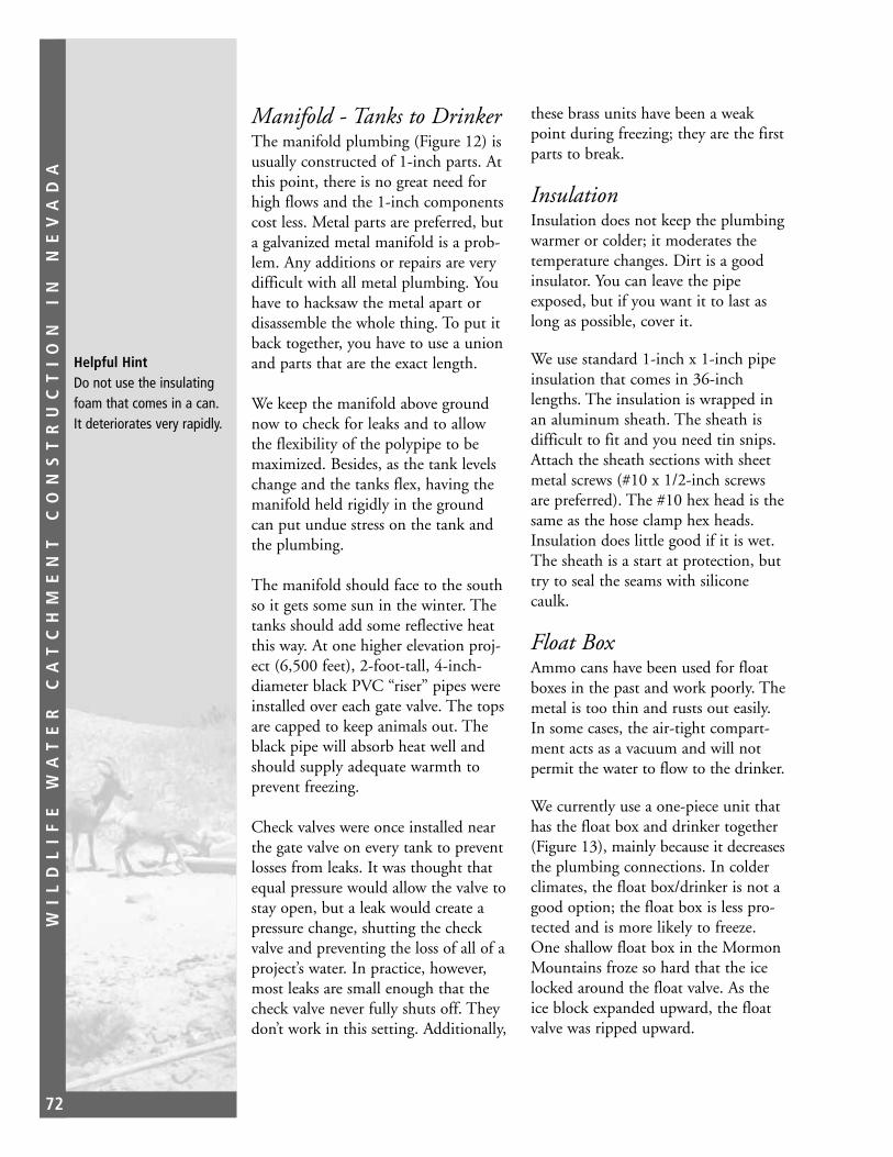
WI
LD
LI
FE
W
AT
ER
C
AT
CH
ME
NT
C
ON
ST
RU
CT
IO
N
IN
N
EV
AD
A
72
Manifold - Tanks to DrinkerThe manifold plumbing (Figure 12) isusually constructed of 1-inch parts. Atthis point, there is no great need forhigh flows and the 1-inch componentscost less. Metal parts are preferred, buta galvanized metal manifold is a prob-lem. Any additions or repairs are verydifficult with all metal plumbing. Youhave to hacksaw the metal apart ordisassemble the whole thing. To put itback together, you have to use a unionand parts that are the exact length.
We keep the manifold above groundnow to check for leaks and to allowthe flexibility of the polypipe to bemaximized. Besides, as the tank levelschange and the tanks flex, having themanifold held rigidly in the groundcan put undue stress on the tank andthe plumbing.
The manifold should face to the southso it gets some sun in the winter. Thetanks should add some reflective heatthis way. At one higher elevation proj-ect (6,500 feet), 2-foot-tall, 4-inch-diameter black PVC “riser” pipes wereinstalled over each gate valve. The topsare capped to keep animals out. Theblack pipe will absorb heat well andshould supply adequate warmth toprevent freezing.
Check valves were once installed nearthe gate valve on every tank to preventlosses from leaks. It was thought thatequal pressure would allow the valve tostay open, but a leak would create apressure change, shutting the checkvalve and preventing the loss of all of aproject’s water. In practice, however,most leaks are small enough that thecheck valve never fully shuts off. Theydon’t work in this setting. Additionally,
these brass units have been a weakpoint during freezing; they are the firstparts to break.
InsulationInsulation does not keep the plumbingwarmer or colder; it moderates thetemperature changes. Dirt is a goodinsulator. You can leave the pipeexposed, but if you want it to last aslong as possible, cover it.
We use standard 1-inch x 1-inch pipeinsulation that comes in 36-inchlengths. The insulation is wrapped inan aluminum sheath. The sheath isdifficult to fit and you need tin snips.Attach the sheath sections with sheetmetal screws (#10 x 1/2-inch screwsare preferred). The #10 hex head is thesame as the hose clamp hex heads.Insulation does little good if it is wet.The sheath is a start at protection, buttry to seal the seams with siliconecaulk.
Float BoxAmmo cans have been used for floatboxes in the past and work poorly. Themetal is too thin and rusts out easily.In some cases, the air-tight compart-ment acts as a vacuum and will notpermit the water to flow to the drinker.
We currently use a one-piece unit thathas the float box and drinker together(Figure 13), mainly because it decreasesthe plumbing connections. In colderclimates, the float box/drinker is not agood option; the float box is less pro-tected and is more likely to freeze.One shallow float box in the MormonMountains froze so hard that the icelocked around the float valve. As theice block expanded upward, the floatvalve was ripped upward.
Helpful HintDo not use the insulatingfoam that comes in a can.It deteriorates very rapidly.

WI
LD
LI
FE
W
AT
ER
C
AT
CH
ME
NT
C
ON
ST
RU
CT
IO
N
IN
N
EV
AD
A
73
Figure 12. Standard manifold plumbing.
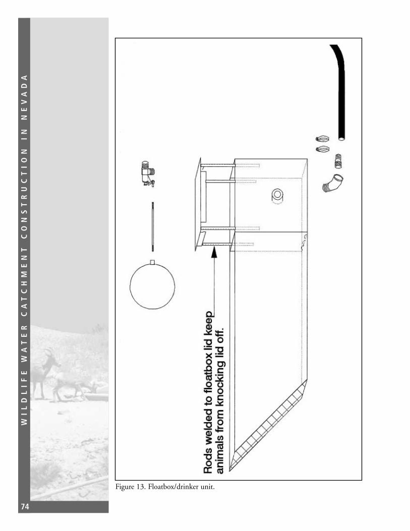
WI
LD
LI
FE
W
AT
ER
C
AT
CH
ME
NT
C
ON
ST
RU
CT
IO
N
IN
N
EV
AD
A
74
Figure 13. Floatbox/drinker unit.

WI
LD
LI
FE
W
AT
ER
C
AT
CH
ME
NT
C
ON
ST
RU
CT
IO
N
IN
N
EV
AD
A
75
One advantage to a separate floatboxand drinker is keeping the critical floatvalve away from the intensive animaluse area. Inadvertent damage is possibleas animals congregate. Several times whenprojects have dried up, sheep have pawedand banged the lid off the float box. Inone case, the float ball was pinned downby the lid; if water had been collectedlater, it would have been lost immedi-ately. Horses and cattle have also donethis to some antelope developments.
The separate floatbox/drinker alterna-tive also has problems. Since the boxcan be located anywhere in relation tothe drinker, if its placement is not welldocumented, it can be difficult or evenimpossible to locate for repair andmaintenance.
Sometimes the float box is buried severalfeet. Other times it is buried and coveredwith insulation. Both of these situationsare difficult to inspect or repair.
The most critical part of the project isthe float valve. We use 1-inch brassfloat valves. Since this part causes themost problems, projects that can doaway with it are more desirable.
Keep the overflow pipe vertical at thetanks. If you slope the pipe, you couldbe making it a ramp for animals. Aslight upturn of the overflow pipealong its length traps water and willinhibit unwanted intruders.
The float ball can be a problem.Originally, we used plastic or rubberfloat balls. These can last for manyyears in a domestic situation, but ourfloat balls are subjected to extremes intemperatures; they crack and leak. Weswitched to a 4-inch copper float balland had no problems until we tried tofill them with foam. It was insulating
Plumbing in parts of western Canada is simplyburied 5 to 6 feet, with acovered culvert sunk tothat level to allow accessto valves. The temperatureof the soil keeps theplumbing from freezing.A water drill is sometimesused to create a shaftbelow the plumbing,increasing the movementof heat from the earth.
foam and worked for several years.Then the foam began soaking up waterand the float balls sank. Those werereplaced with unaltered 6-inch copperfloat balls. The larger float balls dictatea lower drinker level, but they close thefloat valve with more force than the4-inch units. When the drinker level isadjusted, the 1/4-inch x 6 1/2-inchbrass float rod (one-piece drinker) isoften “tweaked” up or down. A littlebending is okay, but it can be broken.Use the longest rod possible; shorterrods reduce your ability to adjust thewater level. Never use a substitute rod;it will corrode and bend, allowing theproject to drain.
More water has been lost due toimproper float adjustment than anysingle mechanical failure. Most often,the float is adjusted and the inspectorwalks away. If the valve is not closed,the slight drip may take hours to detect.With any adjustment, you must waitand watch for an hour before you leave.
Lay the float box lid sideways over thebox. Pull the float ball up and makesure the ball cannot touch the lid. Tryto leave a minimum gap of 1/2 inchbetween the ball and the lid. Overfillthe drinker to check it.
Any mechanism is more likely to fail atthe extremes of its functions. In thecase of the float valve, this is fully upor fully down. Place a fist-sized rockunder the float ball; the rock keeps theball, and thus the float valve, fromgoing all the way down. It reduces thechance that the valve will be stuckdown, preventing the project fromfilling. There is not much you can doabout the valve sticking in the up posi-tion; the larger float ball and the maxi-mum length of float rod should helpto keep this from happening.

WI
LD
LI
FE
W
AT
ER
C
AT
CH
ME
NT
C
ON
ST
RU
CT
IO
N
IN
N
EV
AD
A
76
DrinkerDrinker location is vital. Do not putthe drinker in a situation that gives anadvantage to predators. Water sourcesare where desert bighorns are the mostvulnerable, and predators depend onthese places to focus on prey species.Desert sheep often watch the area of awater source for hours before they goin to drink. Then they drink and moveaway.
Animals are rough around a drinker.Sheep, for example, can wear rutsaround a drinker, leaving it standingon a pedestal of dirt. Virtually everydrinker has to have cement and rocksplaced around it. Cement at least oneanimal body length away from thedrinker. The best situation is to place thedrinker on a sheet of rock, if possible.
Make sure you have a way to protectand cover the line coming in to thedrinker. It should be buried, but thealuminum insulation sheath can pro-tect the pipe as long as the animalscan’t move the pipe.
Do not cement too heavily over theinflow point for the drinker; you mayneed to make repairs or check for leaksat the point of attachment.
Where freezing is a big concern, the drinker should taper upward.Expanding ice will push upward. One suggestion is to provide a flexiblecushion for the ice to push against insquare drinkers or walk-in drinkers;bunched hypalon or a rubber materialshould work. Reflective heat can alsobe used to reduce ice by placing thedrinker on the south face of a boulder.
Rocks are placed in all drinkers. Metaldrinkers have abrupt corners, and unless
a rock is placed in the back, lizards andmice can and will swim into the cornerand paddle until they drown. The rockprovides a place to crawl out onto. Italso displaces water and provides anirregular surface to heat up, increasingthe melting of ice that forms.
Construction in the mid-1980sinvolved a separate float box anddrinker. The float box was made ofsheet metal. The drinkers were bowl-shaped and formed from cement. Theyfunction well, but several have leakedwhere the pipe comes in through thecement. The cement drinkers alsoseem to promote algae buildup morethan sheet metal or plate steel drinkers.
FencesA post and wire fence on a MormonMountains Project was constructed tokeep horses out. The standard BLMwildlife specification (16 feet 10 inches– 8 feet 6 inches) also kept sheep out.Deer would jump the fence, but sheepwere not comfortable with this. Thewires were bunched to form a 20-inchto 22-inch separation around thedrinker area and sheep use increaseddramatically.
Sheep fence specifications allow foranimals to go under and throughfences. The first wire or pole is 18 to20 inches from the ground, the secondis 6 to 8 inches above that, and theoptional top wire or rail is about 42inches above the ground (Figure 14).
There has been some experimentationwith a single-rail fence in horse coun-try. The rail is set at 36 to 38 inches.Horses cannot get under, nor are theyinclined to go over. The problemcomes when you add cattle or burrosthat will go under the rail.

WI
LD
LI
FE
W
AT
ER
C
AT
CH
ME
NT
C
ON
ST
RU
CT
IO
N
IN
N
EV
AD
A
77
Besides watching the rail spacings, makesure to allow room between the drinkerand the fence so predators cannot trapstartled animals against it. Most workto date recommends a minimum of100 feet from the drinker for all fencing.
While it is best not to create an inhibi-tive barrier until wildlife has begun touse the project, once they do, they’llpush a fence very hard to get back to
it. A solution is to install a fence withgates. The wildlife is accustomed to thefence, but when the livestock invade,gate panels will drop into place.
For bighorn sheep, you can incorporatecliffs or rock outcrops into the barrier.The sheep should more readily use thecliffs as “openings” in the fence, butlivestock will still be deterred.
Figure 14. Fence spacings.
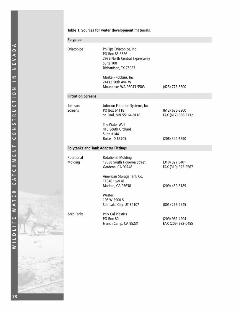
WI
LD
LI
FE
W
AT
ER
C
AT
CH
ME
NT
C
ON
ST
RU
CT
IO
N
IN
N
EV
AD
A
78
Table 1. Sources for water development materials.
Polypipe
Driscopipe Phillips Driscopipe, IncPO Box 83-38662929 North Central ExpresswaySuite 100Richardson, TX 75083
Maskell-Robbins, Inc24113 56th Ave. WMountlake, WA 98043-5503 (425) 775-8600
Filtration Screens
Johnson Johnson Filtration Systems, IncScreens PO Box 64118 (612) 636-3900
St. Paul, MN 55164-0118 FAX (612) 638-3132
The Water Well410 South OrchardSuite #144Boise, ID 83705 (208) 344-6690
Polytanks and Tank Adapter Fittings
Rotational Rotational MoldingMolding 17038 South Figueroa Street (310) 327 5401
Gardena, CA 90248 FAX (310) 323-9567
American Storage Tank Co.11040 Hwy 41.Madera, CA 93638 (209) 439-5189
Westec195 W 3900 S.Salt Lake City, UT 84107 (801) 266-2545
Zorb Tanks Poly Cal PlasticsPO Box 80 (209) 982-4904French Camp, CA 95231 FAX (209) 982-0455

WI
LD
LI
FE
W
AT
ER
C
AT
CH
ME
NT
C
ON
ST
RU
CT
IO
N
IN
N
EV
AD
A
79
Table 1. (cont)
Fiberglass Tanks and Drinkers
Desert Sun Fiberglass Systems, Ltd.21412 N. 14th Avenue (623) 869-0907Phoenix, AZ 85027 FAX (623) 869-9291
Fiberglass Structures, Inc119 South Washington AvenuePO Box 206 (406) 628-8208Laurel, MT 59044 FAX (406) 628-2480
Cargo Nets and Straps
International Cordage, Inc (310) 435-89161657 West 16th (310) 437-0101Long Beach, CA 90813 FAX (310) 435-2410
Liner Aprons
Hypalon Water Saver Company, IncPO Box 16456 (303) 289-1818Denver, CO 80216-0465 FAX (303) 287-3136
Environmental Liners, Inc2009 N. Industrial RoadCortez, CO 81321 (303) 565-4221
PE Liners Gundle Lining Systems, Inc1340 East Richey RoadHouston, TX 77073 (713) 443-8564
Poly-America, Incattn: Poly-Flex Div2000 W Marshall DriveGrand Prairie, TX 75051 (972) 647-4374
National Seal Company600 N. First Bank Dr.Palatine, IL 60067
Miscellaneous
Hand Tools Bailey’sPO Box 55044650 Hwy. 101 (707) 984-6133Laytonville, CA 95454 FAX (707) 984-8115

WI
LD
LI
FE
W
AT
ER
C
AT
CH
ME
NT
C
ON
ST
RU
CT
IO
N
IN
N
EV
AD
A
80
Table 2. Polyethylene tank sizes.*
Capacity Diameter Total Height Weight(Gallons) (Lbs.)
30 1'11" 1'5" 18
500 4'0" 6'1" 133
1000 6'0" 5'4"
1000 5'4" 5'9" 140
1600 7'6" 5'6"
1600 7'8" 5'0" 282
2300 7'6" 7'7" 450
2500 7'10" 8'1" 485
3000 7'6" 9'10"
3000 8'0" 8'6" 640
5000 9'11" 9'10" 1100
6500 9'10" 11'9"
16400 4"0" 16'6" 4200
* Figures from two manufacturers

WI
LD
LI
FE
W
AT
ER
C
AT
CH
ME
NT
C
ON
ST
RU
CT
IO
N
IN
N
EV
AD
A
81
Chapter 4-AerialTransportation ofMaterials and EquipmentHelicopterTransportMany guzzlers are located at sites thatcan be driven to, which simplifieslogistics and makes the entire con-struction process easier. However, asignificant number are located inremote sites, which necessitates the useof helicopters.
Helicopters are expensive and poten-tially very dangerous, but they haveproven to be an essential part of guz-zler construction. Eight of the 29 biggame units in the Carson City Districtrequired the use of helicopters. Theseunits were all located in desert bighornsheep habitat.
The majority of the helicopters we useare small, either Bell Jet Rangers,Hughes 500 Cs or Ds, or Bell 47 (oldMASH type) Soloy Conversions, pow-ered by the same type of turbineengine as that used in the Jet ranger orHughes 500. Personnel are usually allthat is carried inside these helicopters,although never if there is anything onthe hook.
Larger helicopters, such as the Bell204/205/212 (Hueys), can accommo-date items like the 18-foot steel beams
carried crosswise, with both ends ofeach beam sticking out from the heli-copter several feet on each side.
Many things need to be consideredwhen using helicopters, especially ifyou work for an agency within theU.S. Department of the Interior(USDI) or for the Forest Service (FS).These include safety; paperwork/forms;load preparation; staging; external loadequipment; sling operations; and coor-dination between the helicopter pilotand the ground crew.
While the following information is notall-inclusive, it is based on many yearsof sling experience by both authors,not all of which was devoted to mov-ing only guzzler materials or construc-tion equipment.
SafetyPersonnel safety is first and foremost.Agency personnel, especially thoseemployed by the Bureau of LandManagement (BLM) or the FS, workunder a set of no-nonsense rules thathave evolved over the past 20 years,and have been developed and imple-mented by the Interior Department’sOffice of Aircraft Safety (OAS). In thelast decade, several game and fish agen-cies have adopted all or part of theserules as well.
The reader is stronglyurged to obtain a copy ofthe Department of theInterior’s InteragencyHelicopter OperationsGuide (IHOG). It can beordered from NIFC Supply.Ask for NFES 1885.

WI
LD
LI
FE
W
AT
ER
C
AT
CH
ME
NT
C
ON
ST
RU
CT
IO
N
IN
N
EV
AD
A
82
OAS rules require that all personnelworking in, under, and close to heli-copters (such as a sling operation) wearwhat is called “Personnel ProtectiveEquipment” (PPE). PPE includes spe-cial fire-retardant clothing (Nomtex),either flight suites or pants/shirts;Nomex or leather gloves; and hardhat/goggles or flight helmet/gogglesor visor. Wearing this equipment ismandatory for BLM employees.Personnel should also wear non-syn-thetic clothing such as cotton or woolunder the PPE as this adds anotherlayer of protection (it chars but doesnot melt.) The value of Nomex clothingis that it resists flash fires. PPE andnon-synthetic clothing are the bestprotection against severe burns.
Proper training is also important.Many people who routinely hook loadsunder hovering helicopters have hadno formal training; they learned “onthe job.” While formal training maynot be essential for non-Governmentpersonnel, it is required for Federalagency people. If you do not have thetraining necessary to do helicoptersling work, make an effort to getsomeone who is experienced to helpyou, such as helitack or qualifiedresource personnel.
Paperwork/FormsBefore anything can be moved, twothings are required:
1. The maximum allowable load inpounds for the helicopter, consider-ing pressure, altitude, elevation, andtemperature, must be determined.
2. The loads you assemble must notexceed the maximum allowableload, including the weight of theswivel/net/choker/sling.
Department of the Interior agencies useHelicopter Load Calculation (OAS-67)forms to figure the weight of the load.A sample of this form and the instruc-tions for filling it out is shown inFigure 1. BLM regulations require thata “load calc” accompany the documen-tation sent to BLM so the aircraftowner can be paid. There is no need todo a load calc for every load. Instead,determine the allowable load using thehighest elevation at which the helicop-ter will be working and the warmesttemperature you anticipate. Keep inmind that the allowable load willincrease as the helicopter burns off fuelduring the operation.
Load PreparationEvery item must be weighed, marked,and the weight recorded for future ref-erence. We use duct tape and felt-tippens to mark the items. Materials andequipment should be weighed beforebeing sent to the work site to save timeand effort during the sling operationitself. A spring-type Chatillon scale isused if an agency helitack crew doesthe weighing; otherwise a bathroomscale on a firm surface (even a smallpiece of plywood) is adequate.
Load placement inside the helicopteror on the hook is up to the pilot ashe/she has charge of the actual trans-portation. Remember one basic con-cept - the pilot is in command. It ishis/her call whether a load is safe to fly,how it is loaded, and whether the loadmust be jettisoned from the helicopterif it starts to swing erratically or out ofcontrol. That is why, for safety reasons,almost all of the materials and toolsferried into a remote site must be easyto jettison.

WI
LD
LI
FE
W
AT
ER
C
AT
CH
ME
NT
C
ON
ST
RU
CT
IO
N
IN
N
EV
AD
A
83
Figure 1. Form and instructions for determining helicopter’s maximum allowable load.
WI
LD
LI
FE
W
AT
ER
C
AT
CH
ME
NT
C
ON
ST
RU
CT
IO
N
IN
N
EV
AD
A
84
The equipment used in the CarsonCity District for sling operations con-sists of swivels, nets, lead lines, and aspecial sling made of very heavy-dutynylon webbing. We can use a mini-mum of four units, each consisting ofa swivel, a lead line (18 foot) and anet. If you have access to more units,the work will go faster, especially if theturnaround time for each load is short(e.g., less than 6 minutes). The quickturn around time is also why, beforethe helicopter lifts off with the firstload, you should have at least four ormore loads ready to go.
The nets, when stretched open on theground, are 12 feet square and virtuallyeverything except the tanks, tank lids,10-foot gutter assemblies, and steel C-beams can be carried in them.
Strive to center everything in the net(paint the net center orange, if thepaint won’t negatively affect the mate-rial), and when the allowable weight isreached, pull the end/connecting ringspursing the net. Clip the lead linehook to both rings and add a swivel tothe ring/loop of the lead line. Each netload is done this way unless the pilotprefers to fly without the lead line,which is his/her choice.
The swivel, rated at 3,000 poundscapacity, hooks directly to the hook onthe helicopter. Be careful of the alu-minum gates which fit into the open-ings on swivel hooks - these are fairlyfragile and may be bent. Most can bestraightened with vise-grip type pliers.If the gate is bent beyond repair, DO NOT USE THE SWIVEL.
For most loads, this is usually all thepreparation that is necessary. However,
if you have many small boxes full ofhand tools, drills, or light-weightitems, the purse ropes of the netshould be tied together with shortpieces of paracord, or even duct taped.The boxes that house the hand tools,drill bits, oilers, fence parts, and othermiscellaneous items should be tiedtogether so they can’t slip through thenet mesh. The same applies to all handtools such as shovels, pulaskis, anddigging bars. We usually bind thesetogether with duct tape. Obviously,people at both ends of the operationwill have to have cutting tools of somesort (e.g., lockback folder, fixed bladesheath knife, or carton cutter).
The 18-foot steel beams, if slung, arerigged as follows. Take two of the leadlines and make them into chokers.Run the hooked end of the lead lineunder the beam ends and clip it backonto the cable. The first 2 feet fromeach end of the beams should beunsupported to allow the choker cableto slide easily under them. Connectthe two lead line rings with a swiveland the load is ready.
The fiberglass tanks are lightweightand bulky and will become airfoils(out of control) unless they are riggedproperly. We use the special sling men-tioned earlier for the tanks and thelids, and on occasion as a choker forslinging the steel beams.
With a medium-sized helicopter, thesetanks must be slung upside down; onsmaller helicopters, they are slung rightside up with the 10-foot gutter assem-bly pieces nested in them. The gutterpieces, including the white S&D pipeshould be duct-taped together. We alsoput electric cords and cardboard boxes

WI
LD
LI
FE
W
AT
ER
C
AT
CH
ME
NT
C
ON
ST
RU
CT
IO
N
IN
N
EV
AD
A
85
containing parts in them, but no steelboxes or digging tools. If you don’thave a sling, use a cargo net of at least12 square feet.
For the polypropylene tanks, whichweigh 800 pounds empty, a medium(Bell 205) helicopter is preferred;Hughes 500 E’s or Bell 206 LongRangers are marginal.
When using the sling, be very carefulto make sure the sling loops are underthe ends of the tanks far enough sothat they won’t slip off during trans-port. Once the tanks are in the slingand still on the ground, tie the oppo-site sides of the pursing cord of thesling together with paracord in such away that they cannot move. Whenslinging tank lids with this sling, securethe sling loops near the lid ends withshort pieces of paracord threadedthrough the drill holes on the lids andaround the sling loop.
When slinging cubitainers full ofwater, DO NOT sling them with sparegas cans. If the load is not centered,things occasionally spill. NEVER putgasoline atop the water when you areslinging. Consider using small palletsfor a stable platform when moving thewater.
The total weight for a standard bigtime guzzler unit, with fiberglass tanks,plus steel fence for bighorn sheep isroughly 6,200 pounds. If polypropy-lene tanks are used, then add 500pounds. If a 300-foot-long woodbuck-and-rail fence is added, the totalweight goes up another 4,000 pounds(subtract 640 pounds for the steelfence from the 6,200 pounds).
Safety TipMake sure that roof decking/sheeting that isnot already secured in anet as a load is wellanchored as the rotor washfrom the helicopter, even asmall helicopter, will causeunweighted sheets to separate, float, and fly like30-pound knife blades inevery direction.
StagingThe helispot should be as level as pos-sible so the helicopter can land andrefuel safely. It should be large enoughso that the helicopter can land orhover and pick up a sling load. Themore open the area is (i.e., fewer trees,rocks, and/or hills), the better thehelispot will be as it will give the pilotbetter and safer maneuvering room formoving loads and for refueling. A goodapproach and departure route (alwaysmade into the wind) is necessary.
The actual landing pad for a smallhelicopter should be 15 feet x 15 feet,but a 75-foot diameter area is neededfor safe operation. Specifications for amedium-sized helicopter pad are 20feet x 20 feet and a 90-foot diameterarea. The specifications for a heavyhelicopter pad are 30 feet x 30 feet anda 110-foot diameter area. There shouldalso be room at the helispot for thetrucks to maneuver and off-loadmaterials and equipment.
Equip both helispots (staging areaand work site) with a 20-pound fireextinguisher and windsock or at leastengineer’s flagging tied to a pole orradio antennae. Also, stabilize the dustif you can with water or with foamfrom an agency fire truck.
Fueling the helicopter is also part ofthe process. Department of theInterior/OAS rules do not allow hotfueling (while the engine is runningand the blades are turning) unlessthere is a helicopter-to-fuel-truckground and a sealed fueling system.This is usually not present on smallhelicopters, but may be present onsome medium and all large helicopters.

WI
LD
LI
FE
W
AT
ER
C
AT
CH
ME
NT
C
ON
ST
RU
CT
IO
N
IN
N
EV
AD
A
86
For safety purposes, stay at least 50feet from refueling operations. If youmust help with the fueling and arewearing Nomex PPE, be very carefulNOT to get fuel on the PPE as it willnegate its safety features.
Unless the helispot is small, and thehelicopter cannot be refueled exceptright at the staging area, have the fuel-ing done away from the staging area toallow load preparation to continue.Also, there should be no one inside thehelicopter during refueling.
External Load Equipment/Sling OperationsThe number of people needed to do afast-paced sling operation is seven onthe ground - four at the staging areaand three at the work site. The extraperson at the staging area is the load-master, who keeps track of loads andweights. Whoever has the most experi-ence in this type of operation shouldbe designated as helibase manager toproperly coordinate that activity.
Before the first load is hauled, person-nel unloading the nets and equipmentat the work site must be ferried to it.This will require one or two trips if aBell 47 sized helicopter is used. Ifreceiving personnel have not been tothe site, then the job supervisory willhave to show the pilot where the siteis, and one or more ground crew canride at that time. Sometimes the heli-copter arrives at the staging area aheadof the materials and equipment; that isalso a good time for a recon flight.
A typical sling operation scenariowould be as follows: the loadmaster,carrying a hand-held radio and, if pos-sible, wearing a colored vest (to make
him/her stand out from the rest of thecrew for easy identification by thepilot), stands 60 to 100 feet from theload. The task is to direct the pilot,not only during rigging the loads, butduring flight as well.
The helicopter moves up, hoveringover the load, and within reach of thehook up person, who has the swivel inhand. Once the swivel is forced ontothe hook, the hook up person movestoward the loadmaster so the pilot cansee both people, and the pilot lifts theload and proceeds to the destination.The hook-up person should stand sothat he/she will not have to movearound the load toward the loadmasteronce it is hooked up.
The loadmaster indicates either byarm signals or by radio when the leadlines/sling are taut and when the loadis clear of the ground. This is especiallyimportant when a long line - an electrichook at the end of a 50-foot-cable - isused. The hook-up person, to avoidbodily injury, must be very aware ofthe hook at all times, as it is very heavyand usually swinging like a pendulum.Never turn your back on a movinglong-line hook.
Some helicopters develop static elec-tricity and there may be a significantspark arching between the hook, swivel,and hook-up person. Swivels may betouched (grounded) against a helicop-ter skid before rigging the load.Usually this is not necessary on smallhelicopters, but the bigger the ship, thebigger the potential spark.
Before the first load lifts off, theremust be a discussion between the pilot,the loadmaster, and the hook-up person to determine where everyone

WI
LD
LI
FE
W
AT
ER
C
AT
CH
ME
NT
C
ON
ST
RU
CT
IO
N
IN
N
EV
AD
A
87
should go in the event of a helicoptermalfunction during hook up.
As noted above, the loadmaster directsload preparation. This person alsokeeps track of the number of loads andthe weight of each. This is because aload manifest is required when the paydocument is submitted. The loadmas-ter is also in radio communicationwith the pilot for flying conditions,return of empty nets/sling, etc.
When several loads have been ferriedto the work site, the empty nets, leadlines, and swivels are rolled up andplaced in one net. The net is thenslung from the helicopter and releasedby the pilot at the staging area, wheredirected by the loadmaster. A singlenet or two nets should be rolled upand placed in the helicopter. They aretoo light by themselves if slung on thehook and can quickly become airfoilsand create problems.

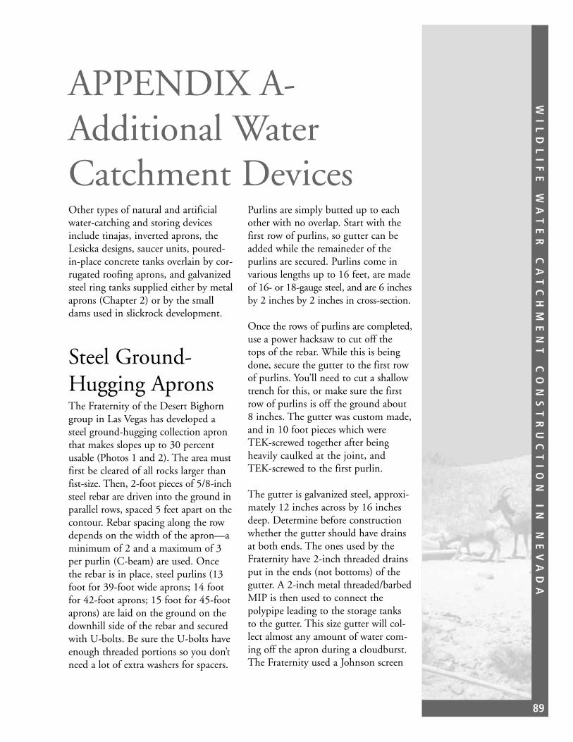
WI
LD
LI
FE
W
AT
ER
C
AT
CH
ME
NT
C
ON
ST
RU
CT
IO
N
IN
N
EV
AD
A
89
APPENDIX A-Additional WaterCatchment DevicesOther types of natural and artificialwater-catching and storing devicesinclude tinajas, inverted aprons, theLesicka designs, saucer units, poured-in-place concrete tanks overlain by cor-rugated roofing aprons, and galvanizedsteel ring tanks supplied either by metalaprons (Chapter 2) or by the smalldams used in slickrock development.
Steel Ground-Hugging ApronsThe Fraternity of the Desert Bighorngroup in Las Vegas has developed asteel ground-hugging collection apronthat makes slopes up to 30 percentusable (Photos 1 and 2). The area mustfirst be cleared of all rocks larger thanfist-size. Then, 2-foot pieces of 5/8-inchsteel rebar are driven into the ground inparallel rows, spaced 5 feet apart on thecontour. Rebar spacing along the rowdepends on the width of the apron—aminimum of 2 and a maximum of 3per purlin (C-beam) are used. Oncethe rebar is in place, steel purlins (13foot for 39-foot wide aprons; 14 footfor 42-foot aprons; 15 foot for 45-footaprons) are laid on the ground on thedownhill side of the rebar and securedwith U-bolts. Be sure the U-bolts haveenough threaded portions so you don’tneed a lot of extra washers for spacers.
Purlins are simply butted up to eachother with no overlap. Start with thefirst row of purlins, so gutter can beadded while the remaineder of thepurlins are secured. Purlins come invarious lengths up to 16 feet, are madeof 16- or 18-gauge steel, and are 6 inchesby 2 inches by 2 inches in cross-section.
Once the rows of purlins are completed,use a power hacksaw to cut off thetops of the rebar. While this is beingdone, secure the gutter to the first rowof purlins. You’ll need to cut a shallowtrench for this, or make sure the firstrow of purlins is off the ground about8 inches. The gutter was custom made,and in 10 foot pieces which wereTEK-screwed together after beingheavily caulked at the joint, andTEK-screwed to the first purlin.
The gutter is galvanized steel, approxi-mately 12 inches across by 16 inchesdeep. Determine before constructionwhether the gutter should have drainsat both ends. The ones used by theFraternity have 2-inch threaded drainsput in the ends (not bottoms) of thegutter. A 2-inch metal threaded/barbedMIP is then used to connect thepolypipe leading to the storage tanksto the gutter. This size gutter will col-lect almost any amount of water com-ing off the apron during a cloudburst.The Fraternity used a Johnson screen

WI
LD
LI
FE
W
AT
ER
C
AT
CH
ME
NT
C
ON
ST
RU
CT
IO
N
IN
N
EV
AD
A
90
Photo 1. Rows of purlins in place.
Photo 2. Completed apron in background.
for each drain hole (there were 2 atone end) within the gutter, to trap anydebris or sediment washing off theapron or surrounding area.
Fraternity of the Desert BighornP.O. Box 27494Las Vegas, NV 89126-1494Phone (702) 458-5858Email [email protected]

WI
LD
LI
FE
W
AT
ER
C
AT
CH
ME
NT
C
ON
ST
RU
CT
IO
N
IN
N
EV
AD
A
91
TinajasTinajas are natural tanks, water-scoured over time by high runoff ingranite canyon and wash bottoms inthe hot desert ranges found mostly inArizona and California. These vary insize from a few inches deep, holding afew gallons of water, to 15 feet deep,holding hundreds of gallons of waterafter thunderstorms. The ArizonaDesert Bighorn Sheep Society (ADBSS)based in Phoenix, Arizona, with helpfrom the Arizona Game and FishDepartment, has improved manydozens of these tinajas by enlargingand sealing them, and building shadestructures over them.
Sealing the rock is an element criticalto their success, and the ADBSS,through its experience and in a paperpublished by Robert S. Gray, one ofit’s early presidents, has become expertat it. The paper, which was preparedand presented at the 1973 annualmeeting of The Desert BighornCouncil, explains in step-by-stepfashion the materials and methodsneeded to seal the tinajas. That paperis included in the Technical Note asAppendix B.
The same process is used for sealingconcrete-and-rock dams, and naturalor blasted stone cisterns, which are alsoa specialty fo the ADBSS. The methodshave well withstood the test of time.
Arizona Desert Bighorn SheepSocietyP.O. Box Drawer 7545Phoenix, Arizona, 85011Phone (602) 912-5300
InvertedAprons/UmbrellasInverted aprons/umbrellas consist of alarge (up to 10,000 gallons) circular,corrugated steel tank overlain by a cir-cular apron of galvanized steel. Thiscircular apron is usually much largerthan the diameter of the tank. Theapron serves as the roof of the tank.These have been used mainly inArizona, New Mexico, and Californiaby game and fish agencies, the BLM,and the Forest Service. Many havebeen in existence since the 1960s.Depending upon the size of the storagetank, the bottom of the tank may bepoured concrete.
Lesicka DesignThe Lesicka Design is fairly recentand is used primarily in SouthernCalifornia and Western Arizona. Itcollects thunderstorm water flowingunder the surface in larger desert washes.
The perforated collection pipe is usuallyplaced underground across a majorwash or drainage that runs well. Asmall (low) dam may be constructed toretard the flow and protect the two ormore 4-inch perforated polyethylenepipe or agricultural drain tiles that areused to collect the water. Surface waterand debris pass over the system, butwater seeping through the sand is con-tinually drawn off. A solid bottom isnot always necessary, but the systemworks best if that is a part of the unit.

WI
LD
LI
FE
W
AT
ER
C
AT
CH
ME
NT
C
ON
ST
RU
CT
IO
N
IN
N
EV
AD
A
92
The trenches for the collection pipeand drainpipe are cut with a backhoe.Six to 8-inch pipe is used for carryingwater to the storage system to accom-modate the very large, short-termflows that are the rule rather than theexception in that part of the world.
Leon M. Lesicka4780 Highway 111Brawley, California, 92227Phone (619) 344-7073
Second LesickaDesignThe Second Lesicka Design collectswater from a natural apron, such asdesert pavement, or from a small secondary wash draining two or moreacres. The wash should be of coarsegravel, rocks, or hardpan. A low dam,usually 18-inches high or so, is suffi-cient. Water backing up behind it isdrained through a screened 6-inch pipeto the holding tank and drinker. This issimilar to the design used in southernNevada (Chapter 3).
For both systems, Lesicka uses 10,000-gallon fiberglass fuel tanks for storage.The 8-foot tall by 30-foot long tanksare completely buried for protection.The walk-down drinker is made offiberglass, and is 8-feet tall, 4-feetwide, and 16-feet long. It is self levelingwith the tanks and is connected byflexible underground plumbing. Thebottom of the drinker is made of concrete to provide durability.
Leon M. Lesicka4780 Highway 111Brawley, California, 92227Phone (619) 344-7073
Saucer UnitsSaucer units (also referred to asdesert discs, parabolic discs, or flyingsaucers), are a patented design marketedby Fiber Erectors of Red Bluff,California, which also makes a varietyof other fiberglass products. They arecircular, made of heavy fiberglass, andrange in diameter from between 9 to16feet. Storage capacity ranges frombetween 200 to 2,200 gallons, depend-ing upon configuration of the bottom(parabolic or flat). They are a bolt-together device and have up to 40 feetof seams. The roofs of these units alsoserve as their collecting aprons.
They have been tried throughoutNevada, California, and Utah, withvarying success. The problems associat-ed with them include lack of adequatecollection surface and leakage. One ofthe big game units in the BLM’sCarson City District had to berecaulked. The BLM’s Ely and LasVegas Districts installed seven of thelarge units and only one continues tofunction. The U.S. Fish and WildlifeService has replaced one of its units.Members of the Society for theConservation of Bighorn Sheep (south-ern California), in conjunction withthe California Department of Fish andGame personnel, report that the oneunit that does function worked afterthe seams had been resealed with fiber-glass. On the other hand, the BLMMoab Utah District installed several ofthe large units over a several-year spanand no maintenance problems havebeen identified.
Another problem identified with thelarger units is that it takes several peo-ple to turn over the bottom, once itsfour quarters are caulked and bolted

WI
LD
LI
FE
W
AT
ER
C
AT
CH
ME
NT
C
ON
ST
RU
CT
IO
N
IN
N
EV
AD
A
93
together. The manufacturer says thatthe bottom may be stood on edge andallowed to flop, being cushioned by airas it approaches the ground. While thisworks fine on forest duff, most ofNevada and Southern California hastoo many rocks to chance breaking theunit by doing this.
Fiber ErectorsPO Box 1009Red Bluff, California 96080Phone (916) 527-1515
ConcreteTanks/DrinkersConcrete tanks/drinkers were used bythe Arizona Game and FishDepartment in the 1960s and 1970s.They consisted of a poured-in-placeconcrete tank, 2 to 3 feet deep, rectan-gular shaped, with a 2,500 galloncapacity. One feature was a walk-downdrinker that was poured at the sametime at one end of the unit. Watersimply moved between the storagetank and the drinker through a holecut in the wall. It was basically an earlyversion of a self-leveling system. Theapron consisted of steel corrugatedroofing, 25 feet by 60 feet, which servedas the roof of the storage tank. Theapron sat almost level at ground level.
Many of these concrete tanks werefilled via concrete collecting aprons.Many of the units, where deer use isheavy, are being revisited andimproved. Up to three, 3,150 gallon
fiberglass storage tanks are buried near-by and provide water for a walk-intrough. These buried systems are beingused in wilderness areas to reduce theneed to haul water to the heavily usedoriginal tanks. The sites are completelylandscaped and restored to their nor-mal status, leaving virtually no trace ofthe construction work.
Arizona Desert Bighorn SheepSocietyPO Drawer 7545Phoenix, Arizona, 85011Phone (602) 912-5300
Galvanized SteelRing TanksGalvanized steel ring tanks, suppliedeither by aprons or slickrock catch-ments, are currently being built by theArizona Game and Fish Departmentand the Arizona Desert Bighorn SheepSociety. These storage structures typi-cally hold 15,000 gallons of water.Animals drink from a fiberglass trough,and the system is self-leveling. Thetanks utilize a polyethylene floor, andChemical Industrial Membrane (CIM)is used to seal the joints of the ringtank itself. A steel roof is constructedover the ring tank and essentiallysealed to prevent evaporation.
Arizona Desert Bighorn SheepSocietyPO Box 7545Phoenix, Arizona, 85011Phone (602) 912-5300

WI
LD
LI
FE
W
AT
ER
C
AT
CH
ME
NT
C
ON
ST
RU
CT
IO
N
IN
N
EV
AD
A
94
Final NotesHere are some tips based on the authors’experience over the past 30 years in theintense sun and temperature extremesfound in Nevada.
• DO NOT use wood structures tosupport aprons; they deterioratequickly and burn readily in rangefires.
• Storage bags made of butyl rubberdeteriorate in sunlight and are
subject to hoof damage by largewildlife, such as mule deer anddesert bighorns if they get on top ofthe bags searching for the water.
• Fiberglass collecting aprons, tried inthe mid-1970s in BLM’s CarsonCity District, did not withstand theultraviolet light from the sun andwere also very easily vandalized.
• Collecting aprons made of rubbersheeting and asphalt both deterioratequickly unless constantly maintained.

WI
LD
LI
FE
W
AT
ER
C
AT
CH
ME
NT
C
ON
ST
RU
CT
IO
N
IN
N
EV
AD
A
95
Appendix B

WI
LD
LI
FE
W
AT
ER
C
AT
CH
ME
NT
C
ON
ST
RU
CT
IO
N
IN
N
EV
AD
A
96

WI
LD
LI
FE
W
AT
ER
C
AT
CH
ME
NT
C
ON
ST
RU
CT
IO
N
IN
N
EV
AD
A
97


The mention of company names, trade names, or commercial products does not constitute endorsement or recommendation for use by the Federal Government.
