cover note with aa logo - hong kong international...
TRANSCRIPT

Important Note
Airport Authority Hong Kong (AAHK) is responsible for preparing the Hong Kong International Airport (HKIA) Master Plan 2030 and commissioning the associated consultancies. At different stages of these consultancies, the consultants produced various documents for AAHK’s consideration, culminating in the production of final reports. Where a final report was not produced, the consultants’ work was consolidated into the HKIA Master Plan 2030 Technical Report. As the reports were produced at different times, they may contain outdated or inconsistent contents.
The HKIA Master Plan 2030 was not drawn up solely on the basis of the various consultancies commissioned by AAHK, but also has incorporated input from relevant airport stakeholders as well as AAHK’s own input on the basis of its solid experience in airport operations. Hence, for any differences between the consultancy reports and the HKIA Master Plan 2030, the latter and the Technical Report should always be referred to.
Airport Authority Hong Kong
July 2011

Commercial in Confidence
Page 1 of 76 Issue 2 Draft V.3 17/12/2008 © NATS 2008
Reference: Deliverable P5 Appendix A Approved By: Project Manager
AIRSPACE AND RUNWAY CAPACITY STUDY PHASE 1b
Deliverable P2
Final Report
Commercial in Confidence
Page 2 of 76 Issue 3.1 17/12/2008 © NATS 2008
Reference: Deliverable P2 Final Report Approved By: Project Manager
Intentionally Blank
Commercial in Confidence
Page 3 of 76 Issue 3.1 17/12/2008 © NATS 2008
Reference: Deliverable P2 Final Report Approved By: Project Manager
EXECUTIVE SUMMARY
This study investigated the possible modes of operation and associated capacities for two and three runway airports at HKIA operating in revised PRD airspace. Whilst the airspace design is outside the scope of this study, it is assumed to provide a northern circuit at HKIA and long final approach tracks (in the order of 20NM) in both runway directions. The interactions of an expanded HKIA operation with the surrounding airfields will need to be taken into consideration in the PRD airspace design process.
An assessment of the ILS performance to support parallel approaches has been undertaken. The proposed modes of operation of the three runway system have been reviewed, outline ATC procedures proposed and recommendations made on the issues identified including compatibility with the ICAO SOIR manual and wake vortex.
The operation of the existing two runway airport has also been examined to identify any capacity benefit from operating with the revised PRD airspace. A small benefit (increasing from 68 to around 71 movements per hour) was identified for the airport operating in Segregated Mode with the reduction in contingency in arrival spacing, but no benefit was identified by changing to Mixed Mode operations on two runways.
The analysis of the ILS has confirmed that the localiser performance is satisfactory out to 20NM from touchdown (the glidepath has yet to be assessed), however the terrain in the vicinity of the airfield prevents the use of the breakout manoeuvre defined in the SOIR manual, so an alternative breakout manoeuvre has been proposed. This would permit Independent Parallel Approaches for Runway Options P and R, but not for Option S Extended or the existing runways where Dependant Parallel Approaches are required and runway capacity is necessarily reduced.
As a result, Options P and R can support a potential capacity of 102 movements per hour (or up to 105 with the reduction in contingency in arrival spacing) comprising 50/53 Arrivals and 52 Departures, while Option S Extended has a potential capacity of 97 movements per hour (46.5 Arrivals and 50.5 Departures). In order to resolve a number of issues, a new Option S Extended Variant F is proposed and it is recommended that Option S Extended Variants A to E are not pursued further.
The assessment and declaration of capacity and schedule limits becomes more complex with the three runway airport. When the balance of traffic varies from the ideal mixture of inbounds and outbounds or northbounds and southbounds, then there is the risk that some capacity may be wasted. An effective scheduling mechanism must ensure that the traffic flows are balanced as far as possible throughout the hour, and throughout the day, while including an allowance for the fact that the maximum movement rates will not be achieved in each hour. In non-optimum hours, capacity may be reduced in the order of 10 to 20%.
Specific safety cases need to be developed for each of the SOIR non-compliant areas covering, as a minimum; parallel approaches, the breakout manoeuvre and wake vortex, in the case of Option S Extended. To support this, it is proposed that the application of RNP 0.3 to SIDs and Missed Approaches that diverge by less than 30 degrees should be studied, together with an analysis of actual track keeping accuracy.
The ground manoeuvring issues for each option were assessed. Options P and R work well, but the number of crossings of the centre runway is of concern in Option R. In the case of Option P, further work is required on the design and operation of taxiways to allow traffic to taxi independently while the centre runway is in use. There are concerns with Option S Extended about the high number of crossings of the centre runway and congestion on Taxiways A and B, north of the existing Terminal. The provision of new southern link taxiways is required to make this option workable.
Further work is required on detailed ATC procedures (on the ground and in the air), a detailed review of Terminal and Compass modes of operation based on an updated traffic forecast and schedule including, the requirement to keep the number of

Commercial in Confidence
Page 4 of 76 Issue 3.1 17/12/2008 © NATS 2008
Reference: Deliverable P2 Final Report Approved By: Project Manager
crossings within an acceptable level, and a detailed implementation plan developed, including the relevant equipment and staffing issues. Real time simulation is required to validate the air and ground issues. The development of the revised PRD airspace must be conducted as a matter of urgency in order to allow the capacity increase associated with the third runway to be realised.
In order to select a final runway option a study should now be undertaken to balance the capacity gain of each option against the construction costs and timescales, the environmental issues, and other factors such as connectivity.

Commercial in Confidence
Page 5 of 76 Issue 3.1 17/12/2008 © NATS 2008
Reference: Deliverable P2 Final Report Approved By: Project Manager
GLOSSARY *A Star Alliance
A Arrival
AAHK Airport Authority Hong Kong
ACC Area Control Centre
AIP Aeronautical Information Publication
AMC Air Movement Controller
AMN Air Movement Controller North
AMS Air Movement Controller South
AMSTS Aircraft Movement Statistics System
APP Approach Sector
APU Auxiliary Power Unit
ARR/Arr Arrivals
ATC Air Traffic Control
ATCO Air Traffic Controller
ATFCM Air Traffic Flow and Capacity Management
ATM Air Traffic Management
BCF Boundary Crossing Facilities
CAD Civil Aviation Department Hong Kong
CAT Category
CD Compact Disc
CDC Clearance Delivery Controller
CONF Configuration
CNS/ATM Communications, Navigation, & Surveillance for Air Traffic Management
D Departure
DA Decision Altitude
DDM Difference in Depth of Modulation
deg Degree
DEH Departure High Sector
DEM Digital Elevation Model
DEP Departure Sector
DEP/Dep Departures
DFS Deutsche Flugsicherung
DH Decision Height
DME Distance Measuring Equipment
Doc Document
E East
EAT Expected Approach Time
ETA Expected Time of Arrival
ETD Expected Time of Departure
EU Evaluation Unit
FAD Final Approach Director Sector
FCOM Flight Crew Operations Manual

Commercial in Confidence
Page 6 of 76 Issue 3.1 17/12/2008 © NATS 2008
Reference: Deliverable P2 Final Report Approved By: Project Manager
FIR Flight Information Region
FL Flight Level
FLO Flow Controller
ft Feet
FTE Flight Technical Error
GBAS Ground Based Augmentation system
GMC Ground Movement Controller
GMN Ground Movement Controller North
GMS Ground Movement Controller South
GNSS Global Navigation Satellite System
GP Glidepath
HK Hong Kong
HK CAD Hong Kong Civil Aviation Department
HKFIR Hong Kong Flight Information Region
HKIA Hong Kong International Airport
IAS Indicated Airspeed
I/B Inbound
ICAO International Civil Aviation Organisation
ILS Instrument Landing System
L Left
LCE Local Competency Examiner
m Metre
MAP Missed Approach Point
MATC Manual of Air Traffic Control
MCH Macau High Sector
MCL Macau Low Sector
MF Midfield
MLS Microwave Landing System
MLW Maximum Landing Weight
MM Mixed Mode
MMD Mott MacDonald1
MOPS Minimum Operational Performance Specifications
MTOW Maximum Take Off Weight
MVMT Movements
NM/Nm Nautical Mile
NOZ Normal Operating Zone
NSE Navigation system Error
NTZ No Transgression Zone
O/B Outbound
OLS Obstacle Limitation Surface
OW Oneworld Alliance
PANS Procedures for Air Navigation Services
1 All reference to Mott MacDonald also refers to Mott Connell.
Commercial in Confidence
Page 7 of 76 Issue 3.1 17/12/2008 © NATS 2008
Reference: Deliverable P2 Final Report Approved By: Project Manager
PANS OPS Procedures for Air Navigation Services - Aircraft Operations
PBN Performance Based Navigation
PDG Procedure Design Group
PDT Procedure Design Team
PRD Pearl River Delta
R Right
Ref/REF Reference
RESA Runway End Safety Area
RET Rapid Exit Taxiway
RFL Requested Flight Level
RHZ Runway Holding Zone
ROT Runway Occupancy Time
RNP Required Navigation Performance
RRSM Reduced Runway Separation Minima
RSS Root Sum Squared
RTCA Radio Technical Commission for Aeronautics
RVA Radar Vectoring Area
Rwy Runway
S South
SAR Special Administrative Region
SARP Standards & Recommended Practices
SDD Situation Data Display
SID Standard Instrument Departure
SOIR Simultaneous Operations on Parallel or Near Parallel Instrument Runways
ST Skyteam Alliance
STAR Standard Instrument Arrival
TAAM Total Airport & Airspace Modeller
TCAS Traffic Alert & Collision Avoidance System
TMA Terminal Control Area
TME Terminal Radar Control East Sector
TMS Terminal Radar Control South Sector
TOGA Take Off Go Around
TRE Area Radar Control East Sector
TRK Area Radar Control East Arrivals Sector
TRN Area Radar North Sector
TRS Area Radar South Sector
TRU Area Radar Upper Sector
TRW Area Radar West Sector
TSE Total System Error
Twy Taxiway
UK United Kingdom
Var Variant
VCR Visual Control Room

Commercial in Confidence
Page 8 of 76 Issue 3.1 17/12/2008 © NATS 2008
Reference: Deliverable P2 Final Report Approved By: Project Manager
VH/VHHH Hong Kong
VM/VMMC Macau
W West
WP Work Package
WV Wake Vortex

Commercial in Confidence
Page 9 of 76 Issue 3.1 17/12/2008 © NATS 2008
Reference: Deliverable P2 Final Report Approved By: Project Manager
CONTENTS
1 INTRODUCTION ............................................................................................. 11 2 SCOPE OF WORK............................................................................................ 11
2.1 Overview................................................................................................... 11 2.2 Stage 1: Two Runway Operations ................................................................. 11 2.3 Stage 2: ILS Data Analysis........................................................................... 12 2.4 Stage 3: Three Runway Operations ............................................................... 13 2.5 TAAM Modelling.......................................................................................... 14 2.6 Procedure Design Group (PDG) work ............................................................. 14
3 OVERVIEW OF WORK PROGRAMME ................................................................... 14 3.1 Deliverables............................................................................................... 15
4 METHODOLOGY.............................................................................................. 15 5 ASSUMPTIONS ............................................................................................... 16 6 BACKGROUND................................................................................................ 16
6.1 ICAO SOIR Manual...................................................................................... 16 6.2 Parallel Approaches..................................................................................... 16
7 ATC PROCEDURE ISSUES................................................................................. 19 7.1 Parallel and Staggered Approach Issues......................................................... 19 7.2 Departure and Missed Approach SOIR Compliance Issues ................................. 22 7.3 Wake Vortex Issues .................................................................................... 22 7.4 Runway Stagger ......................................................................................... 24
8 CAPACITY...................................................................................................... 24 9 STAGE 1: TWO RUNWAY OPERATIONS .............................................................. 25
9.1 Segregated Mode........................................................................................ 25 9.2 Mixed Mode ............................................................................................... 26 9.3 Prior to PRD Airspace .................................................................................. 27
10 STAGE 2: ILS DATA ANALYSIS ......................................................................... 29 10.1 Basic Principles .......................................................................................... 29 10.2 ILS Analysis............................................................................................... 31 10.3 Summary of ILS Analysis (SOIR Compliant Breakout) ...................................... 31 10.4 Alternative Technology ................................................................................ 32 10.5 Hong Kong Breakout Manoeuvre ................................................................... 32 10.6 Summary of ILS Analysis (Proposed Breakout Manoeuvre) ............................... 34
11 STAGE 3: THREE RUNWAY OPERATIONS............................................................ 35 11.1 Initial Investigation of Modes of Operation ..................................................... 35 11.2 Detail Review of Modes of Operation for each Runway Option............................ 40 11.3 Summary of the Review of Options P and R .................................................... 40 11.4 Summary of the Review of Option S Extended (All Variants) ............................. 43

Commercial in Confidence
Page 10 of 76 Issue 3.1 17/12/2008 © NATS 2008
Reference: Deliverable P2 Final Report Approved By: Project Manager
12 PDG ANALYSIS............................................................................................... 48 12.1 07R Missed Approach Turning Right............................................................... 48 12.2 07C Departure Turning Left.......................................................................... 49 12.3 25L Missed Approach Turning Left ................................................................. 49 12.4 25L SID Turning Left................................................................................... 50 12.5 15 degree Separation between SID and Missed Approach ................................. 50
13 GROUND MANOUVERING ISSUES...................................................................... 53 13.1 Options P and R.......................................................................................... 53 13.2 Option S Extended Variant F ........................................................................ 55 13.3 Runway Crossings....................................................................................... 61
14 TAAM WORK .................................................................................................. 63 15 AIRBORNE CROSSOVERs ................................................................................. 65 16 SCHEDULING aND CAPACITY DECLARATION....................................................... 67
16.1 Hourly Capacity.......................................................................................... 67 16.2 Annual Capacity ......................................................................................... 68
17 SAFEGUARDING FOR FUTURE ROUTES .............................................................. 68 18 INTERACTIONS WITH ADJACENT AIRFIELDS ...................................................... 69
18.1 Macau....................................................................................................... 69 18.2 Shenzhen .................................................................................................. 70 18.3 TMA operations .......................................................................................... 70
19 IMPLEMENTATION PLAN .................................................................................. 70 20 RECOMMENDATIONS ...................................................................................... 72 21 CONCLUSIONS............................................................................................... 73
Commercial in Confidence
Page 11 of 76 Issue 3.1 17/12/2008 © NATS 2008
Reference: Deliverable P2 Final Report Approved By: Project Manager
1 INTRODUCTION
This document represents Deliverable P2, the Final Report of the Airspace and Runway Capacity Study Phase 1b being conducted by NATS (Services) Limited for the Airport Authority of Hong Kong. The detailed ILS analysis, the review of modes of operations, the review of breakout manoeuvres for parallel approaches, and the TAAM modelling are each covered in a separate Appendix.
This study investigates the ILS performance (actual performance in respect of the existing runways and expected performance based on computer modelling for the new runway), and addresses the third runway options as identified in the Phase 2 Report. Once the ability of the ILS (or alternative technology systems) to perform independent parallel approaches has been established, the proposed modes of operation of the 3-runway system will be reviewed. Basic high-level ATC procedures have been proposed and recommendations made on the other issues identified including compatibility with the ICAO SOIR manual and wake vortex issues.
The results of these investigations will also be applied to the existing airport to determine the potential maximum capacity of the 2-runway operation at HKIA within the revised PRD airspace.
2 SCOPE OF WORK
2.1 Overview
In Phase 1b of the Airspace and Runway Capacity Study, a high-level investigation of the operations of the existing 2 runway and 3 runway configurations in a revised PRD airspace has been conducted.
Stage 1 of the Phase 1b Study reviews the current two runway scenario at HKIA using the redesigned PRD airspace and proposes potential solutions to increase capacity. Stage 2 investigates the ILS performance (actual for the existing runways and anticipated for the new runway) in order to establish the ability of the ILS (or other technology) to support parallel approaches. Stage 3 reviews the ATC procedures and capacity for the 3 runway airport based on the outcome of these investigations.
2.2 Stage 1: Two Runway Operations
Stage 1 looks at the 2 existing runways operating in the PRD airspace. This covers both segregated and mixed mode operations. Independent parallel approaches or staggered approaches will be required, and as highlighted in the Phase 2 work, these will need to be conducted outside the 10NM final described in the ICAO SOIR manual. A final of around 18-20NM will likely be required in the Runway 25 direction and 16-18NM in the Runway 07 direction.
The ability to conduct mixed mode operations (either independent parallel approaches or staggered approaches), and the capacity achievable, depends on the outcome of the ILS study and the identification of the relevant SOIR compliance and ATC procedure issues. High level draft ATC procedures for these operations have been produced, taking these issues into account.
A new SID and Missed Approach from Runway 25L that diverge by 15 degrees must be designed to provide separation from SIDs from the centre and north runway. A new missed approach procedure from Runway 07L is required that turns 45 degrees left (30 degrees from the Runway 07C SID). These have been designed on a “proof of concept” basis, as was done for Phase 2, to support the planned mode of operations.
Commercial in Confidence
Page 12 of 76 Issue 3.1 17/12/2008 © NATS 2008
Reference: Deliverable P2 Final Report Approved By: Project Manager
The radar vectoring techniques, spacing regime and traffic mix have been reconsidered in order to assess the maximum capacity that can be achieved. Procedure changes and controller training to implement the new regime have been recommended.
The output of Stage 1 consists of:
• Runway capacity of the 2 runway system operated in segregated and mixed mode in revised PRD airspace;
• Recommendations on new sequencing techniques, procedure changes and training;
• Recommendations on any technological enablers required;
• Identification of potential issues from implementing simultaneous parallel and/or staggered approaches (e.g. Airspace crossovers and ground control complexity);
• Indication of the elements required in an implementation plan to support any identified capacity increase; and
• High level identification of any potential issues caused by the new approaches to Hong Kong with traffic from neighbouring airports.
2.3 Stage 2: ILS Data Analysis
This stage involves the analysis of ILS flight check data to determine if the performance of the existing ILS systems will enable simultaneous parallel and/or staggered approaches to be performed.
The scope of the ILS analysis includes:
• The analysis of ILS accuracy for ILS separation during parallel approaches;
• Assessment of potential alternative navigational aids for positional approach onto the ILS and/or instead of ILS;
• Assessment of staggered separation;
• Review of flight check data for assessment of ILS structure and tolerance compliance; and
• Modelling of alternative approaches and of airport environment and assessment of safeguarding practices.
The ILS assessment reviews compliance with the published SOIR criteria and identifies assumptions and activities that will require validation prior to implementation. The data is analysed using known ILS requirements (Annex 10 SARPS) and existing site conditions in order to determine available ILS accuracy and separation.
The identification of the point of ILS separation feeds into the analysis of potential enhancements to the existing ILS and alternative navigational aids and thereby establishes what may be done if the existing facilities cannot support the desired operational requirements.
Due to the terrain effects some approach path modelling work will be carried out using the Ohio ILS tool with CAT III tolerances. The resultant plots will support the outcome of the assessment for parallel approaches.
The ILS issues for the current two 2 runways will also be an issue for the proposed third runway. The same methodology used in the 2-runway analysis has been applied to analyse the ILS systems for the third runway. Since no new runway has been built and no ILS system has been selected or installed, NATS can only model the ILS signal for the third runway and perform an analysis of that model.

Commercial in Confidence
Page 13 of 76 Issue 3.1 17/12/2008 © NATS 2008
Reference: Deliverable P2 Final Report Approved By: Project Manager
Each of the three selected options from Phase 2 (Options P, Option R and Option S Extended, including Variants) have been addressed.
The outcome of the ILS assessment determines the ability of the existing and 3- runway combinations to support independent parallel approaches. Provided that the ILS signal is not significantly degraded by the terrain, then it is likely that these operations can be supported using ILS. In the event that the desired performance is not achieved, then other technology such as MLS (Microwave Landing System) or GNSS/GBAS (Global Navigation Satellite System with Ground Based Augmentation System) are likely to be available as an alternative and information on these alternatives has been included in the report. In addition, the ILS work may be used to establish criteria that will ensure the best opportunity of protecting the potential operational capability of the third runway. These criteria may include best equipment and landscaping criteria, and advisement for procedures, technology and minimal impact to operations under all weather conditions.
ILS flight check data is used to enable an analysis of the ILS accuracy and aircraft navigation performance out to 25NM to be undertaken. The analysis is focused on:
• Types of antenna systems and equipment installed at HKIA;
• Flight check results from previous 2 years;
• Details of potential/future navaids equipment purchases; and
• Dimensions of applied critical and sensitive areas, and holding points associated with CAT II and CAT III.
The output of Stage 2 consists of:
• Results from ILS analysis:
o Assumptions;
o List of findings;
o List of issues, if any;
o Proposed preliminary solutions to any identified issues; and
o Proposed implementation strategy and indicative scheduling.
2.4 Stage 3: Three Runway Operations
Stage 3 considers the runways operating in the PRD airspace, covering both segregated and mixed mode operations. Independent parallel or staggered approaches will be required, and as highlighted in the Phase 2 work, these will need to be conducted outside the 10NM final described in the ICAO SOIR manual. A final of around 18-20NM will likely be required in the Runway 25 direction and 15NM in the Runway 07 direction.
The relevant SOIR compliance, wake vortex and ATC procedure issues have been identified and high level draft ATC procedures developed for the planned modes of operation, taking into account the issues identified. The radar vectoring techniques, spacing regime and traffic mix have been reconsidered in order to assess the maximum capacity that can be achieved. Procedure changes and controller training to implement the new regime have been recommended.
The output of Stage 3 consists of:
• Runway capacity for each option of the 3-runway system operated in revised PRD airspace;
• Recommendations on new sequencing techniques, procedure changes and training;
Commercial in Confidence
Page 14 of 76 Issue 3.1 17/12/2008 © NATS 2008
Reference: Deliverable P2 Final Report Approved By: Project Manager
• Recommendations on any technological enablers required; and
• High level identification of any potential issues caused by the new approaches to Hong Kong with traffic from neighbouring airports.
2.5 TAAM Modelling
The TAAM (Total Airport and Airspace Modeller) software is used to create realistic 4D (3D plus time) models of the airspace and airport environment that can be used to facilitate decision support, planning and analysis of airspace and airport operations. It can simulate traffic at a detailed level, down to ground and gate operations at the airport or on a wide scale covering large areas of airspace.
A suitable predicted traffic sample is created to represent the future anticipated demand in the area, or at the airport, and this is then analysed in fast time enabling various scenarios to be examined, and the designs optimised in an iterative manner based on the outcome of the simulations.
NATS TAAM expert worked in close coordination with the Operational Experts to analyse the airspace crossover issues and ground operations. Various modes of operation were considered, including Terminal or Compass modes of operation.
2.6 Procedure Design Group (PDG) work
The PDG input was based on the work previously undertaken in the Phase 2 study and analysed a number of issues associated with the design of SIDs and Missed Approach procedures to support the recommended modes of operation. This work must be considered as “proof of concept” in nature and detailed design work will need to be undertaken once a particular runway option and mode of operation is chosen.
In addition to the simulation work required for the development of all procedures, it is important for aircraft operators to be consulted in relation to the various factors which affect the design of the flight procedures with significant turns and higher than normal climb gradients. This is particularly relevant in the case of the missed approach procedures over Castle Peak, and the possibility of missed approach procedures which involve an immediate turn. It is essential to ensure pilot acceptance of these procedures, and that pilots understand the reasons that rigid adherence to these procedures is essential to ensure that the design safety criteria are maintained.
3 OVERVIEW OF WORK PROGRAMME
The NATS staff primarily involved in the conduct of this work are:
Chris Danner: Project & Delivery Manager
Paul Johnson: Lead Consultant
Jesse Yuen: TAAM Expert, in-county representative
Keavy Wilson: Commercial Co-ordinator
The work has made significant use of NATS’ operational and simulation experience and the close working methods employed by NATS between these two disciplines.
It must be emphasised that this was a very demanding work programme against very tight timescales. A project such as this would normally be conducted by NATS over a considerably longer timeframe. The results presented herein are as detailed as possible within the agreed scope of the work; however, it is highly likely that further work and/or studies will be required before implementation of the recommendations presented.

Commercial in Confidence
Page 15 of 76 Issue 3.1 17/12/2008 © NATS 2008
Reference: Deliverable P2 Final Report Approved By: Project Manager
3.1 Deliverables
This final report forms the following deliverable of the Phase 1b Study:
Table 3.1 List of Deliverables
Deliverable Description Date Delivered
P2 Final Report containing the outputs from Stages 1, 2 and Stage 3
September 2008
4 METHODOLOGY
When considering a multiple runway airport a systematic approach to the evaluation of likely operating modes is required. The operating modes of each individual runway could be;
• Arrivals Only (A);
• Departures Only (D); and
• Mixed Mode (MM).
For a 2-runway airport, the requirement to balance arrival and departure capacity normally means that only two modes of operation need to be considered. These are Segregated Mode with arrivals on one runway and departures on the other, or Mixed Mode, with arrivals and departures on both runways. These modes may be varied due to local circumstances (such as the desire to use the South runway for cargo aircraft) and to cope with arrival and departure peaks. This report examines these two modes of operation in respect of the existing 2-runway airport.
When considering a 3-runway airport the situation is more complex. As each runway is, in theory, capable of operating in one of these three modes, there are potentially 27 operating modes available for the 3-runway scenario.
These 27 modes are placed in a matrix and each mode evaluated for operability and capacity. At the end of this process a number of core operating modes are identified as suitable for further investigation.
The core modes are then analysed in detail including Easterly and Westerly operations and a definitive view given on the likely capacity of each mode along with any limitations.
Finally, a primary operating mode for both Easterly and Westerly operations is defined. Other subsidiary modes may also be identified that would be suitable to deal with arrival and departure peaks.
Once the modes of operation have been identified, two types of analysis are conducted. Firstly, it is assumed that the runway option is SOIR compliant, or that suitable mitigations and a safety case are in place to cover any non-compliances. This analysis identifies the maximum potential capacity of the runway option once all SOIR compliance issues have been resolved.
Secondly, the primary operating mode is analysed again taking into account all SOIR non-compliances and proposing ATC procedures to mitigate the issues by accepting a reduction in capacity due to the problem. This provides a capacity figure for the runway option without any mitigation which is likely to be lower than the mitigated figure.
Finally, a recommended mode of operations is identified that can be achieved using the mitigations suggested. This includes the runway capacity that is likely to be achieved assuming the recommended mode of operations, and necessary mitigations, have been implemented.
Commercial in Confidence
Page 16 of 76 Issue 3.1 17/12/2008 © NATS 2008
Reference: Deliverable P2 Final Report Approved By: Project Manager
Future work is then required to develop the detailed ATC procedures and produce a safety case for the runway option and the required mitigation measures.
5 ASSUMPTIONS
The following ICAO guidance is used throughout this evaluation (Ref ICAO Doc 9643):
• Missed approach procedures from adjacent parallel runways must diverge by at least 30 degrees;
• Aircraft departing from adjacent parallel runways must diverge by at least 15 degrees;
• During Segregated Mode parallel operations, the missed approach track from the arrival runway must diverge by 30 degrees from the departure tracks of the adjacent runway; and
• In the event of a missed approach during Independent Mixed Mode operations, the missed approach must diverge by 30 degrees from any Mixed Mode departure from the same runway or an adjacent runway.
6 BACKGROUND
6.1 ICAO SOIR Manual
The ICAO SOIR Manual (Manual on Simultaneous Operations on Parallel or Near-Parallel Instrument Runways (SOIR), ICAO Doc 9643) describes certain standard procedures for operating Parallel Runways. These modes of operation should not be considered exclusive. There will be some cases where the modes of operation will need to be varied due to local requirements such as the runway configuration at a particular airport, or the surrounding terrain. In addition, the manual only covers two runway operations, not 3 runways. Many of the SOIR procedures can be applied to any two runways of the three runway combination, but considerations of the overall interaction of the three runway system will also need to be taken into account. The introduction of any new procedure requires the production of a safety case. When the procedures in the SOIR manual are adopted, the safety case will have to consider the safety requirements in the light of any local factors. Where the SOIR procedure are not adopted, or varied in any way, then a safety case must be developed based on the actual procedures implemented.
There are three types of non-compliance with the SOIR manual relevant to this study:
i) Non-Compliant (E.g. 15 degree separation between SID and Missed Approach)
ii) Extension of an existing concept (E.g. Parallel approaches out to 20nm)
iii) Outside the scope of the SOIR manual (E.g. 30 degree separation between SID and Missed Approach but both turn left)
At Hong Kong these issues are largely due to the surrounding terrain and it is inevitable that local procedures will be required to support some aspects of the three runway operation.
6.2 Parallel Approaches
With 2 runways, there are a number of possible modes of operations according to ICAO’s SOIR manual:
• Mode 1 - Independent Parallel Instrument Approaches: simultaneous parallel approaches to both runways using adjacent ILS/MLS systems. This mode is not currently implemented at HKIA;

Commercial in Confidence
Page 17 of 76 Issue 3.1 17/12/2008 © NATS 2008
Reference: Deliverable P2 Final Report Approved By: Project Manager
• Mode 2 - Dependent Parallel Instrument Approaches: simultaneous staggered approaches to both runways where certain radar separation minima are applied between aircraft using adjacent ILS/MLS systems. This mode is not currently implemented at HKIA;
• Mode 3 - Independent Instrument Departures from Parallel Runway: simultaneous departures for aircraft from parallel runways. This mode is not currently implemented at HKIA; and
• Mode 4 - Segregated Operations on Parallel Runways: simultaneous operations on parallel runways where one runway is used for arrivals and one runway is used for departures.
Mode 4 is currently in use at HKIA, although some of the procedures in use are not fully compliant with the SOIR manual and visual separation and local procedures are used to mitigate this situation. Implementation of the new missed approach procedures in the Phase 1a report would provide a SOIR compliant solution that could be operated in all weather conditions. In addition, some aircraft (mainly freighters and general aviation traffic) are integrated into the system and land on the south runway.
Mode 3 is not currently possible as there are no independent departure tracks off the two runways.
Mode 1 and Mode 2 are also not possible currently for a number of reasons:
• Lack of airspace. These modes require a longer final for Runways 07L/07R, which creates a conflict with Macau traffic;
• The airspace needs to be reorganised to provide for a northern circuit at Hong Kong; and
• The terrain to the east requires aircraft to establish on final approach for Runways 25L/25R at greater than 10NM, which is outside the scope of the SOIR manual. It is therefore not possible to adopt the ICAO SOIR manual procedures as they stand, requiring additional local procedures to be developed.
A standard SOIR procedure supports aircraft intercepting the ILS within 10NM from touchdown at 2000ft and 3000ft from each side of the localizer.
Figure 6.1 ICAO SOIR Procedures for Parallel Approaches
5NM 6.5NM Touchdown
2000ft
3000ft
10NM
Commercial in Confidence
Page 18 of 76 Issue 3.1 17/12/2008 © NATS 2008
Reference: Deliverable P2 Final Report Approved By: Project Manager
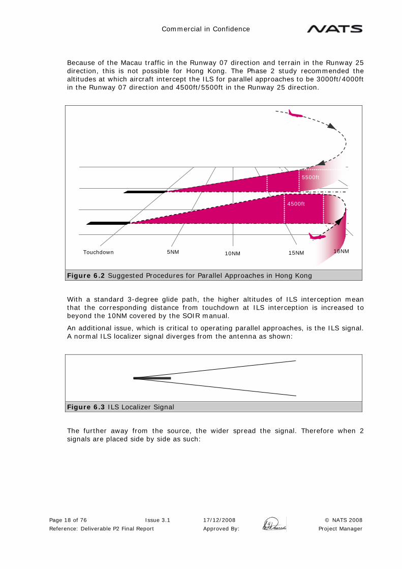
Because of the Macau traffic in the Runway 07 direction and terrain in the Runway 25 direction, this is not possible for Hong Kong. The Phase 2 study recommended the altitudes at which aircraft intercept the ILS for parallel approaches to be 3000ft/4000ft in the Runway 07 direction and 4500ft/5500ft in the Runway 25 direction.
Figure 6.2 Suggested Procedures for Parallel Approaches in Hong Kong
With a standard 3-degree glide path, the higher altitudes of ILS interception mean that the corresponding distance from touchdown at ILS interception is increased to beyond the 10NM covered by the SOIR manual.
An additional issue, which is critical to operating parallel approaches, is the ILS signal. A normal ILS localizer signal diverges from the antenna as shown:
Figure 6.3 ILS Localizer Signal
The further away from the source, the wider spread the signal. Therefore when 2 signals are placed side by side as such:
15NM 10NM 5NM
4500ft
Touchdown 18NM
5500ft
Commercial in Confidence
Page 19 of 76 Issue 3.1 17/12/2008 © NATS 2008
Reference: Deliverable P2 Final Report Approved By: Project Manager
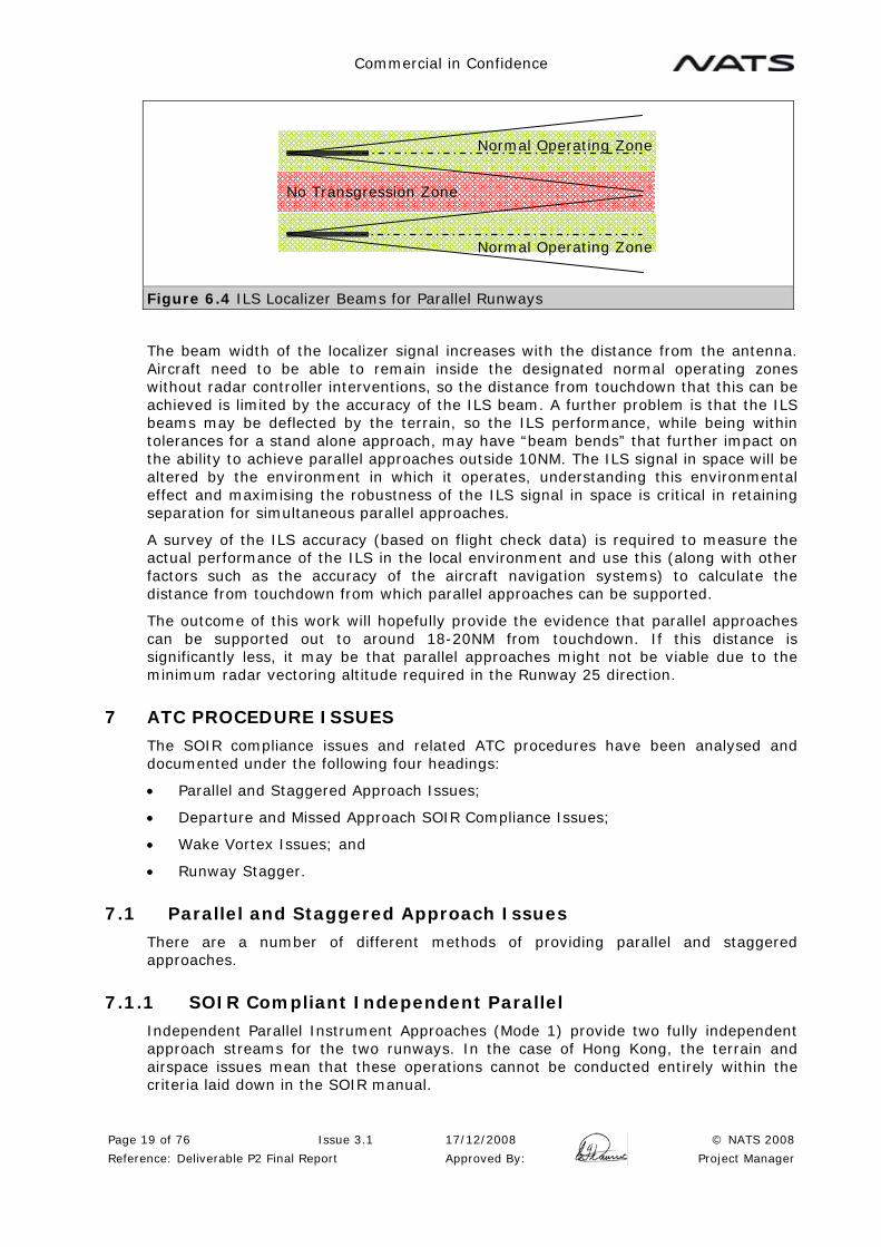
Figure 6.4 ILS Localizer Beams for Parallel Runways
The beam width of the localizer signal increases with the distance from the antenna. Aircraft need to be able to remain inside the designated normal operating zones without radar controller interventions, so the distance from touchdown that this can be achieved is limited by the accuracy of the ILS beam. A further problem is that the ILS beams may be deflected by the terrain, so the ILS performance, while being within tolerances for a stand alone approach, may have “beam bends” that further impact on the ability to achieve parallel approaches outside 10NM. The ILS signal in space will be altered by the environment in which it operates, understanding this environmental effect and maximising the robustness of the ILS signal in space is critical in retaining separation for simultaneous parallel approaches.
A survey of the ILS accuracy (based on flight check data) is required to measure the actual performance of the ILS in the local environment and use this (along with other factors such as the accuracy of the aircraft navigation systems) to calculate the distance from touchdown from which parallel approaches can be supported.
The outcome of this work will hopefully provide the evidence that parallel approaches can be supported out to around 18-20NM from touchdown. If this distance is significantly less, it may be that parallel approaches might not be viable due to the minimum radar vectoring altitude required in the Runway 25 direction.
7 ATC PROCEDURE ISSUES
The SOIR compliance issues and related ATC procedures have been analysed and documented under the following four headings:
• Parallel and Staggered Approach Issues;
• Departure and Missed Approach SOIR Compliance Issues;
• Wake Vortex Issues; and
• Runway Stagger.
7.1 Parallel and Staggered Approach Issues
There are a number of different methods of providing parallel and staggered approaches.
7.1.1 SOIR Compliant Independent Parallel
Independent Parallel Instrument Approaches (Mode 1) provide two fully independent approach streams for the two runways. In the case of Hong Kong, the terrain and airspace issues mean that these operations cannot be conducted entirely within the criteria laid down in the SOIR manual.
No Transgression Zone
Normal Operating Zone
Normal Operating Zone

Commercial in Confidence
Page 20 of 76 Issue 3.1 17/12/2008 © NATS 2008
Reference: Deliverable P2 Final Report Approved By: Project Manager
Operation of simultaneous parallel approaches outside 10NM is outside the scope of the SOIR manual. However, the basic safety criteria in the SOIR manual can be projected outside 10NM and used as the basis for these procedures. Once the ILS performance has been established, it is possible to calculate if the No Transgression Zone will be infringed, and determine the maximum distance from touchdown from which these approaches can be supported. In the event that this range is not sufficient, either ILS improvement, or alternative technology would be required to support the Hong Kong operation.
Another issue for parallel approaches is a breakout manoeuvre in the event that an aircraft on a parallel approach suffers from poor track keeping or an onboard equipment failure and deviates ("blunders") towards the adjacent approach path. This normally requires ATC to instruct the "threatened" aircraft to climb and turn away from the blundering aircraft. Following the pilot input, the turn manoeuvre is likely to take effect sooner than the climb manoeuvre, resulting in the aircraft turning away and continuing to descend for a period of time until the climb is commenced.
Figure 7.1 Breakout Manoeuvre
Due to terrain in the Runway 25 direction (and possibly on short final in the Runway 07 direction), turning breakout manoeuvres are not possible and alternative breakout manoeuvres will need to be developed during the design of the parallel approach procedures. This creates an additional SOIR compliance issue in that the SOIR manual only refers to breakout manoeuvres which turn and climb. The safety analysis is based on a horizontal miss distance and no provision is made for a safety case based on a vertical miss distance.
Blundering Aircraft
Aircraft operating normally receives a
“breakout manoeuvre”
NOZ NTZ NOZ

Commercial in Confidence
Page 21 of 76 Issue 3.1 17/12/2008 © NATS 2008
Reference: Deliverable P2 Final Report Approved By: Project Manager
Figure 7.2 Independent Parallel Instrument Approaches (Mode 1)
7.1.2 SOIR Compliant Staggered Separation
The SOIR manual describes Dependant Parallel Instrument Approaches (Mode 2) where 2NM diagonal separation is provided between aircraft on adjacent approach paths. The requirements for monitoring are reduced compared to Independent Parallel Instrument Approaches, but the basic requirements for a safety assessment remain with an increased miss distance between aircraft in the event that an aircraft deviates from the centreline. In order to conduct these approaches, an ILS assessment is also required.
Figure 7.3 Dependent Parallel Instrument Approaches (Mode 2)
7.1.3 Radar Separation
It is possible to provide parallel approaches using existing radar separation (normally 3NM). Assuming the runways are less than 3NM apart, this will deliver the aircraft in a staggered formation where the diagonal distance between adjacent aircraft is 3NM. In addition, the required longitudinal separation must be provided between traffic on each approach path.
07L
07R
In Trail Separation e.g. 4NM or 5NM
In Trail Separation e.g. 4NM or 5NM
Min 2NM
Min 2NM Min
2NM
NTZ
NOZ
NOZ
07L 07R
In Trail Separation e.g. 4NM or 5NM
In Trail Separation e.g. 4NM or 5NM

Commercial in Confidence
Page 22 of 76 Issue 3.1 17/12/2008 © NATS 2008
Reference: Deliverable P2 Final Report Approved By: Project Manager
Figure 7.4 Staggered Final Approach using Radar Separation
7.2 Departure and Missed Approach SOIR Compliance Issues
The requirement for separation between SIDs is 15 degrees and between a SID and a Missed Approach procedure is 30 degrees. The separation between the proposed Runway 07C SID and existing Runway 07R Missed Approach cannot be SOIR compliant due to the terrain and requires special attention.
The Missed Approach from Runway 07L and the SID from Runway 07C have been designed with 30 degrees separation (SOIR compliant) but both procedures turn left, which is not covered in the SOIR manual. Similar situations exist at other major airports, and this may be considered acceptable, however there is an additional constraint in that the controller is not able to use radar vectors to resolve any potential conflicts due to the terrain.
Both of these cases require a safety case to support these procedures.
7.3 Wake Vortex Issues
Most of the proposed operations are separated in respect of wake vortex except Option S Extended.
Once the runway offset is reduced below 760m, the degree of stagger can be used to provide separation between departure from the centre runway and the arrival on the north runway, but this stagger does not provide wake vortex separation in respect of a missed approach by a heavy aircraft.
07L 07R
In Trail Separation e.g. 4NM or 5NM
In Trail Separation e.g. 4NM or 5NM
Min 3NM
Min 3NM Min
3NM

Commercial in Confidence
Page 23 of 76 Issue 3.1 17/12/2008 © NATS 2008
Reference: Deliverable P2 Final Report Approved By: Project Manager
Figure 7.5 Wake Vortex Separation Required below 760m Runway Offset
Once the stagger reaches the maximum of 1950m (as could be provided in the Runway 07 direction), the missed approach will turn away before reaching the threshold of the departure runway, and this could be used to mitigate the wake vortex issue. Wake vortex behaviour is complex and local factors such as the terrain, local environment and the meteorological factors including wind, temperature and turbulence can have a significant effect. These local factors need to be taken into account in the development of any safety case.
Figure 7.6 Wake Vortex Situation with Greater than 1800m Stagger
380m
Threshold Runway 25C
1950m
Threshold Runway 25R
Less than 760m
380m
Threshold Runway 25C
1950m
Threshold Runway 25R
Commercial in Confidence
Page 24 of 76 Issue 3.1 17/12/2008 © NATS 2008
Reference: Deliverable P2 Final Report Approved By: Project Manager
In the Runway 25 direction the stagger of 0m (Variants A, B and C) or 1000m (Variants D and E) is not sufficient. The problem only arises when an aircraft landing on Runway 25R conducts a missed approach simultaneously with a departure from Runway 25C. The possibility exists that the wake vortex from the missed approach aircraft might drift into the path of the departure. ATC procedures will be required to mitigate the problem by ensuring that a heavy aircraft conducting a missed approach from Runway 25R does not overtake an aircraft departing from the Runway 25C. Further staggering of runway thresholds in the Runway 25 direction may help to alleviate this problem, and a suitable safety case developed, as in the Runway 07 direction.
7.4 Runway Stagger
The SOIR manual allows runways to be staggered by 150m for every 30m below the minimum of 760m for parallel runways. The offset of S Extended is 380m, meaning that 13 * 150m is required (1950m). However, the actual offset of 380m is equivalent to 122/3 which would equate to a stagger of 1900m if the rule was applied proportionately.
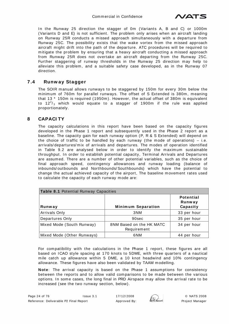
8 CAPACITY
The capacity calculations in this report have been based on the capacity figures developed in the Phase 1 report and subsequently used in the Phase 2 report as a baseline. The capacity gain for each runway option (P, R & S Extended) will depend on the choice of traffic to be handled by each runway (the mode of operations) – i.e. arrivals/departures/mix of arrivals and departures. The modes of operation identified in Table 9.2 are analysed below in order to identify the maximum sustainable throughput. In order to establish potential capacity, Terminal Arrivals and Departures are assumed. There are a number of other potential variables, such as the choice of final approach speed, contingency allowances and runway loading (balance of inbounds/outbounds and Northbounds/Southbounds) which have the potential to change the actual achieved capacity of the airport, The baseline movement rates used to calculate the capacity of each runway mode are:
Table 8.1 Potential Runway Capacities
Runway Minimum Separation
Potential Runway Capacity
Arrivals Only 3NM 33 per hour
Departures Only 90sec 35 per hour
Mixed Mode (South Runway) 8NM Based on the HK MATC Requirement
34 per hour
Mixed Mode (Other Runways) 6NM 44 per hour
For compatibility with the calculations in the Phase 1 report, these figures are all based on ICAO style spacing at 170 knots to 5DME, with three quarters of a nautical mile catch up allowance within 5 DME, a 10 knot headwind and 10% contingency allowance. These figures have also been validated by TAAM modelling.
Note: The arrival capacity is based on the Phase 1 assumptions for consistency between the reports and to allow valid comparisons to be made between the various options. In some cases, the long final in PRD Airspace may allow the arrival rate to be increased (see the two runway section, below).
Commercial in Confidence
Page 25 of 76 Issue 3.1 17/12/2008 © NATS 2008
Reference: Deliverable P2 Final Report Approved By: Project Manager
Note: There is a need to declare airport capacity on an hourly basis taking into account operational demand, mix of aircraft types, operational factors and all other relevant issues such as runway changes, contingency allowances and recovery periods.
Key:
9 STAGE 1: TWO RUNWAY OPERATIONS
The review of the two runway operation was split into three areas covering Segregated Mode in PRD airspace, Mixed Mode operations in PRD Airspace and to identify any opportunities to increase capacity prior to the implementation of PRD Airspace.
No specific design of PRD Airspace was considered, but it is assumed that the following basic principles have been included in the design and implementation:
• A north circuit to HKIA has been provided, capable of supporting departures, arrivals and missed approaches;
• Departure routes to the north are separated from departure routes to the south;
• A long final is available in both runway directions. In the Runway 25 direction, this should commence at a minimum of 18NM from touchdown for terrain clearance. In the Runway 07 direction this needs to provide separation from Macau traffic. In segregated mode this is likely to require a 13NM final at 4000ft. In Mixed Mode, then a low side of 4000ft and high side of 5000ft (16NM) so a final of around 18NM may also be appropriate;
• Suitable TMA procedures, sectors and infrastructure are in place to handle the desired traffic levels; and
• Any technical solutions required are in place and suitably integrated into the PRD ATC infrastructure.
Further details on the implementation issues are provided in the Implementation section below.
9.1 Segregated Mode
In segregated mode, the departure rate is currently constrained by the single SID and 90 second departure interval. In order to increase the departure rate, independent SIDs would be required with a track separation of 45 degrees in order to implement 1 minute departure intervals. The problems with implementing this at Hong Kong are considerable, due to the terrain.
When the runways are used in the existing configuration with the South Runway for Departure and the North Runway for arrivals, adding a second SID from the South Runway at 45 degrees would be a challenge. From Runway 25L it is possible to envisage SIDs turning 15 degrees left and 30 degree right. From Runway 07R, the SIDs would be straight ahead and 45 degrees left. This left turn would be directly towards Castle Peak with a high climb gradient, but would also require an early level off underneath the Shenzhen circuit and the conflict with Shenzhen would be even
Departure
Arrival
Missed Approach

Commercial in Confidence
Page 26 of 76 Issue 3.1 17/12/2008 © NATS 2008
Reference: Deliverable P2 Final Report Approved By: Project Manager
more severe than the 30 degree SID discussed in Appendix B. Both south runway SIDs also conflict with the north runway missed approach.
By changing the current runway usage, the Runway 25L Missed Approach can turn left by 15 degrees. Provided this has been validated against a straight ahead SID from the existing Runway 25R, then a new SID turning 45 degrees right would be possible. This would, however, create some kind of interaction with Shenzhen.
The Runway 07R Missed Approach has to climb straight ahead, meaning that that the SID from the existing Runway 07L must turn left by at least 15 degrees. A second SID would have to turn left by at least 60 degrees, and both SIDs would be turning in the same direction. This problem, together with the proximity of Castle Peak and even more extreme interaction with Shenzhen mean that this SID is not considered to be viable.
As a result, the maximum departure rate will remain at 35/hour in segregated mode.
The arrival rate is currently limited by the short final on Runway 07L. Simply providing a longer final would undoubtedly increase the arrival rate. As a minimum, the long final provides the ability to apply speed control in a more effective manner, which will improve the consistency of the spacing achieved. This is difficult to quantify, but the figures used in the Phase 1 report are based on a specific traffic sample with a mix of 23% Medium and 77% Heavy aircraft. This is used as an example of typical landing rates and can be used to demonstrate the effects on the landing rate of various techniques. The actual landing rates achieved will depend on the actual traffic offering.
The basic landing rate used is 33 arrivals per hour, based on ICAO style spacing, ¾ mile catch allowance, a speed regime of 170knots to 5 DME with a 10 knot headwind and then an additional 10% contingency over and above these figures.
Simply reducing the contingency allowance from 10% to 5% (due to the more consistent spacing) increases the arrival rate from 33 to 34 per hour. It would not be unreasonable to expect that any contingency for controller and pilot performance was included within the ¾ mile catch allowance (this would be the case in the UK) and this produces an arrival rate of 36 per hour.
An alternative would be to change to the NATS style spacing regime where the spacing requirement was applied at 4DME, rather than touchdown. This has the potential to increase the arrival rate to around 37/38 per hour, however this would require a significant training program and a safety case. There are a number of restrictions and conditions to operate this regime which were identified in the Phase 1 report.
Overall, it is considered that the arrival and departure rates could easily be balanced at 35 movements per hour, making total capacity of 70 in Segregated Mode in PRD Airspace. The introduction of NATS style spacing will increase the landing rate above the departure rate and may not allow the scheduled movement rate to increase significantly. This will, however, allow arrival peaks to be handled more effectively and will reduce the impact of delay situations such as adverse weather by increasing the ability to recover from these events.
These potential increases in arrival capacity due to the availability of a long final are also applicable to an arrival runway at the three runway airport.
9.2 Mixed Mode
This considers the possibility of operating the two existing runways in mixed mode, with the assumption that a long final is available in both directions for parallel approaches. The ILS Analysis (see Appendix A) has shown that Independent Parallel Approaches cannot be supported on the existing runways due to the requirement for a long final. This means that some form of dependant approaches are required.

Commercial in Confidence
Page 27 of 76 Issue 3.1 17/12/2008 © NATS 2008
Reference: Deliverable P2 Final Report Approved By: Project Manager
The problem is further compounded by the fact that arrivals and departure on the south runway are dependant, requiring a minimum of 8NM spacing and a movement rate of 34 per hour. It would be possible to design SIDs and Missed Approaches from the north runway that were separated and remove this restriction. Calculations in the Phase 2 report indicate that such a runway would have a capacity of around 44 movements per hour. There are issues with this operation, particularly in some cases where the SID and Missed Approach turn in the same direction.
The key to achieving this increased capacity on the north runway is designing a viable dependant approach regime. To achieve 44 movements per hour on the north runway, final approach spacing of around 6NM is required, but this is dependent on the south runway with spacing of around 8NM. The requirement to ensure at least 2NM staggered spacing between traffic on the adjacent runways with each runway using different spacing would be impractical and is not considered a realistic option. Even if a complex regime was developed it would be difficult to implement and is likely to require wasteful gaps to maintain the dependency, so losing the desired capacity gains.
One option would be to operate mixed mode with 8 miles spacing on both runways. This would maintain capacity at 68 per hour, but might offer more flexibility to deal with arrival and departure peaks, but it would be difficult to justify the considerable training and infrastructure changes (procedures for parallel approaches, an increase from 1 to 2 FAD positions, frequency over-ride facilities, departure management to balance the two runways and the more complex ground movement environment etc) required for no overall capacity gain.
Table 9.1 Two-runway Potential Capacity
Arr Dep Total
Phase 1 Segregated Mode 33 35 68
Longer Final, More Consistent Spacings * 34 35 69
Separate Contingency Allowance Removed * 36 35 71
NATS Style Spacing * 38 35 73
Mixed Mode 34 34 68
*Note: This increase in arrival capacity is also applicable to an arrival runway at the three-runway airport.
9.3 Prior to PRD Airspace
Consideration was given to the idea that some interim solution might be possible to increase the length of final in the Runway 07 direction prior to the implementation of the full PRD airspace redesign. The longer final might enable an increased landing rate in segregated mode, with the Hong Kong airspace operating as described in the Phase 1 report. It was assumed that all the Phase 1 recommendations had been implemented prior to this change in order to support the increased traffic levels.
The long final at Hong Kong (around 15NM) would see Hong Kong arrivals establishing on final approach at 4000ft and then descending on the glidepath. Macau traffic would have to be restricted to 3000ft until at least 5NM clear of the Hong Kong final approach track. This is generally felt to be viable as the 07L final approach track passes just north of Macau when the Macau traffic would normally be below these levels. The particular problem would appear to be the Macau Runway 34 departures via LKC and the Runway 34 Missed Approaches. In order to provide separation from Hong Kong traffic, these have to achieve 5500ft 5NM before the LKC. With climb restrictions imposed by the Hong Kong long final, these routes may have to be extended further north in order to achieve these levels.

Commercial in Confidence
Page 28 of 76 Issue 3.1 17/12/2008 © NATS 2008
Reference: Deliverable P2 Final Report Approved By: Project Manager
Figure 9.1 Possible extension of the Runway 07 Final Approach prior to PRD Airspace
This long final could not be provided in the short term, as it requires the Phase 1 recommendations to be implemented. The changes to the airspace, Macau procedures and the associated agreements between Hong Kong, Macau and mainland China would be substantial for a short term benefit prior to the full PRD implementation, at which time they would be subject to further changes. The scale of this change is not felt to be realistic for a short term benefit and it would be more realistic to concentrate on the objective of achieving the full PRD reorganisation in order to support the increasing demands for capacity in the PRD area and to support the third runway.
In the event that the full PRD airspace implementation was substantially delayed, and this could be implemented without impacting on other changes, then this option could be reconsidered.
Recommendations:
R1: Once PRD Airspace has been implemented, this will improve the consistency of final approach spacing and allow the contingency allowance in the final approach spacing to be reduced or removed and the arrival rate to be increased.
R2: Once PRD Airspace has been implemented the introduction of NATS style spacing at the two runway airport in segregated mode (supported by a suitable training program and safety case) is recommended to further improve the arrival flow.
R3: The operation of the existing runways in Mixed Mode does not deliver a capacity increase and, due to the training and infrastructure changes required, this mode of operations is not recommended.
R4: The design of a long final in the Runway 07 direction, prior to the introduction of PRD airspace re-organisation, is not recommended.

Commercial in Confidence
Page 29 of 76 Issue 3.1 17/12/2008 © NATS 2008
Reference: Deliverable P2 Final Report Approved By: Project Manager
10 STAGE 2: ILS DATA ANALYSIS
Guidance material on simultaneous operations on parallel instrument runways is given in the ICAO SOIR Manual [Ref 1]. This defines two modes of operation for simultaneous parallel approaches; Mode 1, independent parallel approaches and Mode 2, dependent parallel approaches. A significant difference between these modes is that only Mode 1 takes account of lateral navigation errors. An ILS analysis is therefore required to assess the ability on any pair of runways to support independent parallel approaches (Mode 1). Only ILS operations are considered although the procedures are equally applicable to MLS based operations.
Note: The SOIR manual has not been updated to include GBAS, but as GBAS is an ILS look-a-like approach, there is no reason to believe that the SOIR manual criteria cannot be applied to GBAS.
10.1 Basic Principles
The airspace between the parallel runways is separated into two zones, the normal operating zone (NOZ) and the no transgression zone (NTZ). The NOZ is the airspace in which aircraft are expected to operate while manoeuvring to capture and fly the ILS localiser course. There is therefore one NOZ associated with each extended runway centre line. Once established on the ILS the aircraft are expected to remain within the NOZ without radar controller intervention. The NTZ is a corridor of airspace established equidistant between the two extended runway centre lines. The NTZ has a minimum width of 610m and extends from the nearest threshold to the point where the 300m (1000ft) vertical separation is reduced between the aircraft on the adjacent extended runway centre lines. The NTZ defines a zone where monitoring radar controllers must intervene to establish separation between aircraft if any penetration (“blunder” see Figure 7.1) is observed. The separation between parallel runways is therefore determined by combining the NTZ and the inner half of the NOZ for each runway, with a minimum distance of 1035m recommended in ICAO Annex 14.
The NTZ and NOZ are illustrated in the following figure, taken from the ICAO SOIR Manual.
References
[1] Manual on Simultaneous Operations on Parallel or Near-Parallel Instrument Runways (SOIR), ICAO Doc 9643

Commercial in Confidence
Page 30 of 76 Issue 3.1 17/12/2008 © NATS 2008
Reference: Deliverable P2 Final Report Approved By: Project Manager
Figure 10.1 Example of Normal Operating Zones (NOZs) and No Transgression Zone (NTZ)
The width of NTZ is dependent on the time taken to resolve any conflict resulting from a blunder. This consists of instructing the aircraft on the adjacent approach course to commence a breakout manoeuvre. The width of the NTZ takes into account the time taken to detect the blunder and issue the breakout instruction, the time taken for the manoeuvre to take effect plus a minimum miss distance.
The width of the NOZ is dependant on the width of the ILS beam and the ability of the aircraft to follow the beam (the navigation accuracy). As described in Section 6.2 above the width of the ILS beam increases with the distance from the runway. The requirement at Hong Kong for parallel approaches to commence at a range greater than 10NM from touchdown means that the distance between parallel runways to support independent approaches is significantly increased.
Commercial in Confidence
Page 31 of 76 Issue 3.1 17/12/2008 © NATS 2008
Reference: Deliverable P2 Final Report Approved By: Project Manager
A review of the extended glidepath coverage is also required to validate the ability of aircraft can capture the glidepath outside 10NM.
10.2 ILS Analysis
A detailed analysis of the ILS performance of the existing and proposed runway options was undertaken. The ability of each pair of runways to support ICAO Mode 1 independent parallel approaches was then analysed using the basic criteria in the SOIR manual and Annex 10. The ILS analysis is described in detail in Appendix A.
10.3 Summary of ILS Analysis (SOIR Compliant Breakout)
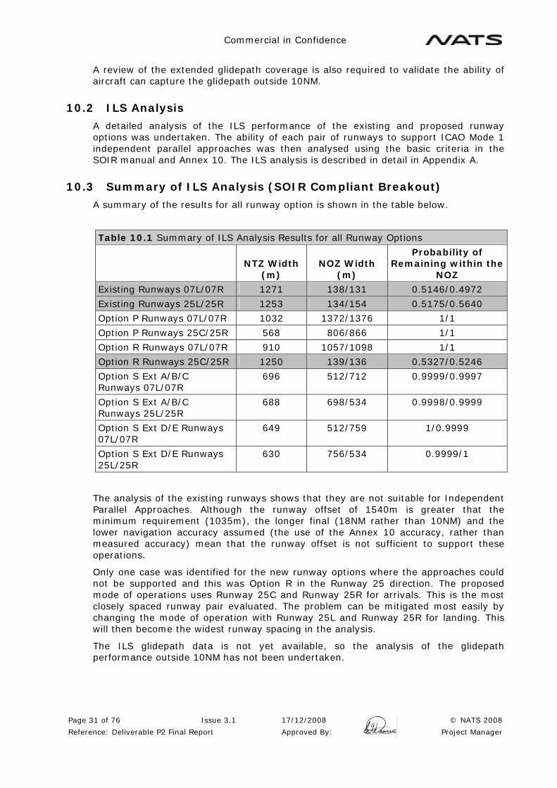
A summary of the results for all runway option is shown in the table below.
Table 10.1 Summary of ILS Analysis Results for all Runway Options
NTZ Width
(m) NOZ Width
(m)
Probability of Remaining within the
NOZ
Existing Runways 07L/07R 1271 138/131 0.5146/0.4972
Existing Runways 25L/25R 1253 134/154 0.5175/0.5640
Option P Runways 07L/07R 1032 1372/1376 1/1
Option P Runways 25C/25R 568 806/866 1/1
Option R Runways 07L/07R 910 1057/1098 1/1
Option R Runways 25C/25R 1250 139/136 0.5327/0.5246
Option S Ext A/B/C Runways 07L/07R
696 512/712 0.9999/0.9997
Option S Ext A/B/C Runways 25L/25R
688 698/534 0.9998/0.9999
Option S Ext D/E Runways 07L/07R
649 512/759 1/0.9999
Option S Ext D/E Runways 25L/25R
630 756/534 0.9999/1
The analysis of the existing runways shows that they are not suitable for Independent Parallel Approaches. Although the runway offset of 1540m is greater that the minimum requirement (1035m), the longer final (18NM rather than 10NM) and the lower navigation accuracy assumed (the use of the Annex 10 accuracy, rather than measured accuracy) mean that the runway offset is not sufficient to support these operations.
Only one case was identified for the new runway options where the approaches could not be supported and this was Option R in the Runway 25 direction. The proposed mode of operations uses Runway 25C and Runway 25R for arrivals. This is the most closely spaced runway pair evaluated. The problem can be mitigated most easily by changing the mode of operation with Runway 25L and Runway 25R for landing. This will then become the widest runway spacing in the analysis.
The ILS glidepath data is not yet available, so the analysis of the glidepath performance outside 10NM has not been undertaken.
Commercial in Confidence
Page 32 of 76 Issue 3.1 17/12/2008 © NATS 2008
Reference: Deliverable P2 Final Report Approved By: Project Manager
10.4 Alternative Technology
Main use of alternative technology would be to improve the approach track keeping performance in the event that the ILS could not support Annex 10 requirements outside 10nm due to terrain. The ILS analysis confirms that the localiser performance is acceptable. The current ICAO standards and implementation of MLS and GBAS meet the same criteria for ILS look-alike, straight in approaches so new technology does not offer a benefit in this respect.
Another method for improving the analysis would be to use measured accuracy (see Appendix A). With ILS and MLS, using measured accuracy has a significant disadvantage in that the safeguarding regime must ensure that new developments and traffic increases do not erode the accuracies and invalidate the safety case for parallel approaches. The GBAS ground station requires suitable safeguarding, but the accuracy issues are different. Although the Annex 10 requirement requires the same ILS look-alike values, in practice some of the accuracy values will not be angular and it can be expected that the accuracy will not deteriorate with range. In addition, the aircraft performance (FTE) is likely to be better as there will be no beam bends or fluctuations due to traffic moving on the airfield. It is not possible to quantify these benefits*, but using measured accuracy is likely to offer an improvement (a reduction in the size of the NOZ) with GBAS. In marginal cases, this will allow Independent Parallel Approaches to be supported by more closely spaced runways.
*As the performance of GBAS will depend on local factors such as terrain, it is difficult to imagine how these benefits could be quantified without installing a GBAS ground station and undertaking a measurement campaign.
The use of other technology (e.g. PBN) for the departure and missed approach phases is covered elsewhere in the document under the SOIR compliance issues.
10.5 Hong Kong Breakout Manoeuvre
The SOIR manual breakout manoeuvre consists of the threatened aircraft being instructed to make an immediate turn and climb. Due to the terrain issues, this breakout manoeuvre is not suitable at Hong Kong and an alternative breakout scenario needs to be developed.
Two alternative breakout manoeuvres have been assessed to try to identify a suitable breakout manoeuvre and parallel approach regime for Hong Kong. A vertical breakout manoeuvre was assessed and not considered to be appropriate. A new proposed breakout manoeuvre was developed which involves turning the blundering aircraft. Full details on the analysis of breakout manoeuvres is provided in Appendix C.
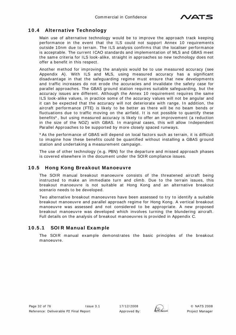
10.5.1 SOIR Manual Example
The SOIR manual example demonstrates the basic principles of the breakout manoeuvre.
Commercial in Confidence
Page 33 of 76 Issue 3.1 17/12/2008 © NATS 2008
Reference: Deliverable P2 Final Report Approved By: Project Manager
Figure 10.2 ICAO SOIR Manual Example
In the event of an aircraft leaving the final approach track (“blundering”), the aircraft on the adjacent final approach track is instructed to turn and climb (the “breakout manoeuvre”).
10.5.2 Proposed Breakout Manoeuvre
As a SOIR type breakout of the threatened aircraft is not viable, the only acceptable possibility is that resolution of the problem could be achieved by turning the blundering aircraft. This is outside the scope of the SOIR manual, which considers that turning the blundering aircraft may not be possible due to a technical problem, or a radio failure. A resolution procedure that involves turning the blundering aircraft has been developed, taking these factors into account. Details of this proposed breakout manoeuvre can be found in Appendix C.
NOZ NOZ NTZ
Detection Zone 275m (6 sec)
Delay Time
300m (8 sec)
Correction Zone 180m (4 sec)
Miss Distance 60m
Blundering Aircraft
Threatened Aircraft Breakout Manoeuvre
Commercial in Confidence
Page 34 of 76 Issue 3.1 17/12/2008 © NATS 2008
Reference: Deliverable P2 Final Report Approved By: Project Manager
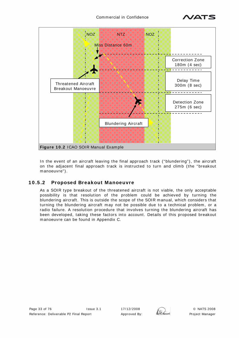
Figure 10.3 Proposed Breakout Manoeuvre Turning the Blundering Aircraft
In order to implement such a procedure, a full safety case is required to validate these principles.
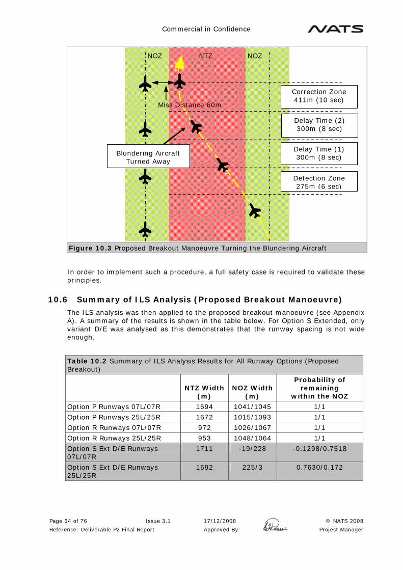
10.6 Summary of ILS Analysis (Proposed Breakout Manoeuvre)
The ILS analysis was then applied to the proposed breakout manoeuvre (see Appendix A). A summary of the results is shown in the table below. For Option S Extended, only variant D/E was analysed as this demonstrates that the runway spacing is not wide enough.
Table 10.2 Summary of ILS Analysis Results for All Runway Options (Proposed Breakout)
NTZ Width
(m) NOZ Width
(m)
Probability of remaining
within the NOZ
Option P Runways 07L/07R 1694 1041/1045 1/1
Option P Runways 25L/25R 1672 1015/1093 1/1
Option R Runways 07L/07R 972 1026/1067 1/1
Option R Runways 25L/25R 953 1048/1064 1/1
Option S Ext D/E Runways 07L/07R
1711 -19/228 -0.1298/0.7518
Option S Ext D/E Runways 25L/25R
1692 225/3 0.7630/0.172
NOZ NOZ NTZ
Detection Zone 275m (6 sec)
Delay Time (1) 300m (8 sec)
Correction Zone 411m (10 sec)
Miss Distance 60m
Delay Time (2) 300m (8 sec)
Blundering Aircraft Turned Away

Commercial in Confidence
Page 35 of 76 Issue 3.1 17/12/2008 © NATS 2008
Reference: Deliverable P2 Final Report Approved By: Project Manager
The increased runway separation (around 2500m) required to support the proposed breakout manoeuvre means that Independent Parallel approaches cannot be supported in Option S Extended (all Variants).
If there was a desire to conduct Independent Parallel Approaches to Option S Extended then a considerable amount of further work would be required. A significant factor in determining the minimum runway spacing is the navigation accuracy (FTE) (See Appendix A). A survey of the actual accuracy achieved in Hong Kong would be required to allow a higher accuracy figure to be applied to the analysis. If this higher accuracy was still insufficient to allow these approaches, then other measures would be required, such as reducing the Correction Zone by allowing for the aircraft turn radius, or removing the second Delay Time and applying other contingency measures. Overall, it would appear that achieving Independent Parallel Approaches to Option S Extended (All Variants) is extremely challenging and it has been considered impractical for the purpose of this study.
11 STAGE 3: THREE RUNWAY OPERATIONS
11.1 Initial Investigation of Modes of Operation
The modes of operation are described for each runway from North to South.
Mode of Operations may be Arrivals only (A), Departures only (D) or Mixed Mode Arrivals and Departures (MM).
For a 3-runway airport each runway is, in theory, capable of operating in one of these three modes, resulting in 27 potential operating modes. These 27 modes have been placed in a table and each mode evaluated for operability and capacity. At the end of this process a number of core operating modes are identified as suitable for further investigation
The outcome of the review is N – Not viable or Y – Suitable for detailed investigation.
Note1: In S Extended, Mixed Mode is not viable on the Northern Pair of runways as they are dependant.
Note 2: An Arrival on the centre runway is not viable as the Missed Approach is not separated from Missed Approaches and Departures from the other runways.
Note 3: The management of triple arrival steams is considered to be unacceptably complex and these modes have been excluded.
Table 11.1 Table of 27 Possible Modes of Operation
Mode of Operations
Option S Extended Option P & R
1. MM/MM/MM N Mixed Mode not viable on the Northern pair of
runways Note1 Complex triple arrival
stream Note3 Complex triple departure
stream
N No acceptable Missed Approach from the centre
runway Note2 Complex triple arrival
stream Note3 Complex triple departure
stream

Commercial in Confidence
Page 36 of 76 Issue 3.1 17/12/2008 © NATS 2008
Reference: Deliverable P2 Final Report Approved By: Project Manager
2. MM/MM/A N Mixed Mode not viable on the Northern pair of
runways Note1 Arrival on the Centre runway not viable Note2
N Arrivals & Departures not balanced.
No acceptable Missed Approach from the centre
runway Note2 Complex triple arrival
stream Note3
3. MM/MM/D N Mixed Mode not viable on the Northern pair of
runways Note1 Arrival on the Centre runway not viable Note2
Complex triple departure stream
N Arrivals and Departures not balanced.
No acceptable Missed Approach from the centre
runway Note2 Complex triple departure
stream
4. MM/A/MM N Mixed Mode not viable on the Northern pair of
runways Note1 Arrival on the Centre runway not viable Note2
N Complex triple arrival stream Note3
Issue with Missed Approach from the Centre
runway and dependent arrival streams
5. MM/D/MM N Mixed Mode not viable on the Northern pair of
runways Note1 Complex triple departure
stream
N Arrivals & Departures not Balanced.
Complex triple departure stream
6. MM/D/D N Mixed Mode not viable on the Northern pair of
runways Note1 Complex triple departure
stream
N Arrivals & Departures not balanced.
Complex triple departure stream
7. MM/A/A N Mixed Mode not viable on the Northern pair of
runways Note1 Complex triple arrival
stream Note3
N Arrivals and Departures not balanced.
No acceptable Missed Approach from the centre
runway Note2 Complex triple arrival
stream Note3
8. MM/A/D N Mixed Mode not viable on the Northern pair of
runways Note1
Y Issue with Missed Approach from the
Centre runway Worthy of further
investigation
9. MM/D/A N Mixed Mode not viable on the Northern pair of
runways Note1
Y Worthy of further investigation
10.D/MM/MM N Mixed Mode not viable on the Northern pair of
runways Note1 Complex triple departure
stream
N Arrivals & Departures not balanced
Complex triple departure stream
No acceptable Missed Approach from the centre
runway Note2
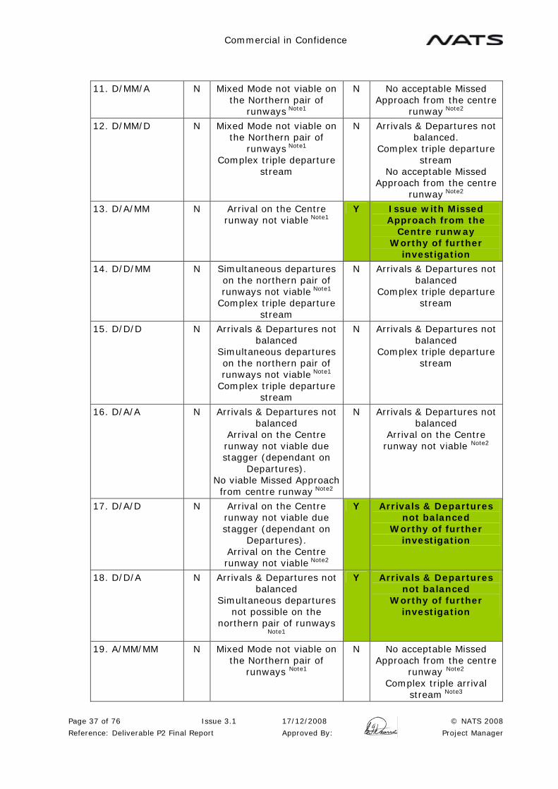
Commercial in Confidence
Page 37 of 76 Issue 3.1 17/12/2008 © NATS 2008
Reference: Deliverable P2 Final Report Approved By: Project Manager
11. D/MM/A N Mixed Mode not viable on the Northern pair of
runways Note1
N No acceptable Missed Approach from the centre
runway Note2
12. D/MM/D N Mixed Mode not viable on the Northern pair of
runways Note1 Complex triple departure
stream
N Arrivals & Departures not balanced.
Complex triple departure stream
No acceptable Missed Approach from the centre
runway Note2
13. D/A/MM N Arrival on the Centre runway not viable Note1
Y Issue with Missed Approach from the
Centre runway Worthy of further
investigation
14. D/D/MM N Simultaneous departures on the northern pair of runways not viable Note1
Complex triple departure stream
N Arrivals & Departures not balanced
Complex triple departure stream
15. D/D/D N Arrivals & Departures not balanced
Simultaneous departures on the northern pair of runways not viable Note1
Complex triple departure stream
N Arrivals & Departures not balanced
Complex triple departure stream
16. D/A/A N Arrivals & Departures not balanced
Arrival on the Centre runway not viable due stagger (dependant on
Departures). No viable Missed Approach from centre runway Note2
N Arrivals & Departures not balanced
Arrival on the Centre runway not viable Note2
17. D/A/D N Arrival on the Centre runway not viable due stagger (dependant on
Departures). Arrival on the Centre runway not viable Note2
Y Arrivals & Departures not balanced
Worthy of further investigation
18. D/D/A N Arrivals & Departures not balanced
Simultaneous departures not possible on the
northern pair of runways Note1
Y Arrivals & Departures not balanced
Worthy of further investigation
19. A/MM/MM N Mixed Mode not viable on the Northern pair of
runways Note1
N No acceptable Missed Approach from the centre
runway Note2 Complex triple arrival
stream Note3
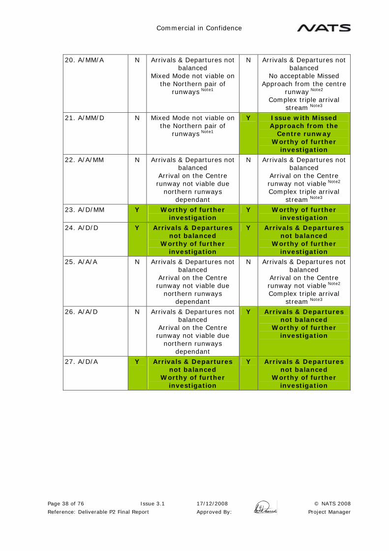
Commercial in Confidence
Page 38 of 76 Issue 3.1 17/12/2008 © NATS 2008
Reference: Deliverable P2 Final Report Approved By: Project Manager
20. A/MM/A N Arrivals & Departures not balanced
Mixed Mode not viable on the Northern pair of
runways Note1
N Arrivals & Departures not balanced
No acceptable Missed Approach from the centre
runway Note2 Complex triple arrival
stream Note3
21. A/MM/D N Mixed Mode not viable on the Northern pair of
runways Note1
Y Issue with Missed Approach from the
Centre runway Worthy of further
investigation
22. A/A/MM N Arrivals & Departures not balanced
Arrival on the Centre runway not viable due
northern runways dependant
N Arrivals & Departures not balanced
Arrival on the Centre runway not viable Note2 Complex triple arrival
stream Note3
23. A/D/MM Y Worthy of further investigation
Y Worthy of further investigation
24. A/D/D Y Arrivals & Departures not balanced
Worthy of further investigation
Y Arrivals & Departures not balanced
Worthy of further investigation
25. A/A/A N Arrivals & Departures not balanced
Arrival on the Centre runway not viable due
northern runways dependant
N Arrivals & Departures not balanced
Arrival on the Centre runway not viable Note2 Complex triple arrival
stream Note3
26. A/A/D N Arrivals & Departures not balanced
Arrival on the Centre runway not viable due
northern runways dependant
Y Arrivals & Departures not balanced
Worthy of further investigation
27. A/D/A Y Arrivals & Departures not balanced
Worthy of further investigation
Y Arrivals & Departures not balanced
Worthy of further investigation

Commercial in Confidence
Page 39 of 76 Issue 3.1 17/12/2008 © NATS 2008
Reference: Deliverable P2 Final Report Approved By: Project Manager
The above analysis identifies that the following viable modes require further evaluation:
Table 11.2 Table of Viable Modes of Operation
Mode of Operations
Option S Extended Option P & R
8. MM/A/D Y Issue with Missed Approach from the
Centre runway Worthy of further
investigation
9. MM/D/A Y Worthy of further investigation
13. D/A/MM Y Issue with Missed Approach from the
Centre runway Worthy of further
investigation
17. D/A/D Y Arrivals & Departures not balanced
Worthy of further investigation
18. D/D/A Y Arrivals & Departures not balanced
Worthy of further investigation
21. A/MM/D Y Issue with Missed Approach from the
Centre runway Worthy of further
investigation
23. A/D/MM Y Worthy of further investigation
Y Worthy of further investigation
24. A/D/D Y Arrivals & Departures not balanced
Worthy of further investigation
Y Arrivals & Departures not balanced
Worthy of further investigation
26. A/A/D Y Arrivals & Departures not balanced
Worthy of further investigation
27. A/D/A Y Arrivals & Departures not balanced
Worthy of further investigation
Y Arrivals & Departures not balanced
Worthy of further investigation

Commercial in Confidence
Page 40 of 76 Issue 3.1 17/12/2008 © NATS 2008
Reference: Deliverable P2 Final Report Approved By: Project Manager
11.2 Detail Review of Modes of Operation for each Runway Option
The three runway options (including variants) have been assessed based on the modes of operation selected from the initial review. The issues have been identified and a number of mitigation measures have been proposed. The capacity of each mode of operation, after implementation of these mitigations has then been assessed.
The review has been undertaken by developing a table for each runway option, for each mode of operation and in both the Runway 25 and the Runway 07 directions. The SOIR compliance issues in respect of parallel approaches, departures, missed approaches and wake vortex are identified in each case. Possible mitigations are then proposed where appropriate and considered to be viable.
Each table contains an assessment of the potential capacity of the airport operating in the chosen mode of operation on the assumption that the issues have been resolved. A final table for each option describes the primary mode of operation and the actual capacity that is likely to be achieved. Due to the significant and complex nature of the issues, particularly the interaction between the various issues, these capacity figures may be significantly lower than the theoretical maximum capacity.
The detailed review and the tables developed are contained in Appendix B.
The result of this is a review of the development of a recommended mode of operation for each runway option. This includes a recommended primary mode of operations where arrival and departure capacities are generally balanced. Modes of operation to deal with arrival and departure peaks are also recommended.
A summary of the review and these recommended modes are described below together with the mitigations that are required to operate these modes, and the capacity achieved with the mitigations in place.
11.3 Summary of the Review of Options P and R
Options P and R have the lowest number of SOIR compliant and operational issues. The outer runways are far enough apart to support Independent Parallel Operations using the proposed breakout manoeuvre. The arrival capacity of the dedicated arrival runway (07L/25R) has been assessed as 33 arrivals per hour for compatibility with the rest of the report. In practice, the improved consistency and reduced contingency margins proposed for two runways in segregated mode could also be applied to this runway which might result in the achievable arrival rate being slightly higher (up to around 36 arrivals per hour).
Significant issues that remain are the ability to apply 15 degrees separation between the missed approach and the SID tracks and the fact that the SIDs and missed approaches, while providing the required track separation, both turn in the same direction. A specific safety case is required to support these operations.
The analysis of Options P and R indicate that Mode 9 (MM/D/A) is the highest capacity mode. However, it requires a SID from Runway 07L that turns left by 30 degrees, and this creates a significant confliction with the Shenzhen circuit. As a result, Mode 9 is not recommended in the Runway 07 direction. This problem does not exist in the Runway 25 direction, as the Runway 25C SID can climb straight ahead, or turn only 15 degrees right, depending on the separation required from Runway 25L. Operating Mode 9 in one direction only does not provided any increase in the declared capacity, as only the lowest capacity can be declared. Operating different modes in each direction creates operational difficulties when changing runway direction and further complicated the process of terminal and runway allocations. As a result, Mode 23 is recommended as the primary mode of operations in both runway directions.

Commercial in Confidence
Page 41 of 76 Issue 3.1 17/12/2008 © NATS 2008
Reference: Deliverable P2 Final Report Approved By: Project Manager
Options P & R Mode 23
A/D/MM Runway
Separation 2240/1525m
RECOMMENDED PRIMARY MODE OF OPERATION
Runway 25 Direction Runway 07 Direction
Runway Use Capacity Arrivals Departures
25R/07L Arrivals 33/36* 33/36* -
25C/07C Departures 35 - 35
25L/07R Mixed 34 17 17
Total 102/105* 50/53* 52
*Note: up to 36 arrivals and total capacity up to 105 movements per hour with the reduction in contingency in the arrival spacing.
Independent Parallel and Dependent Approach Issues and Mitigations
A Safety Case needs to be developed to support independent parallel approaches.
SOIR Departure Issues and Mitigations
Two departure tracks diverge by 15 degrees and there are no departure issues.
SOIR Missed Approach Issues and Mitigations
A Safety Case is required to support the 15 degree separation between the south runway Missed Approach and the centre runway SID. Alternatively, the Runway 25C SID should turn right by 15 degrees, however a straight segment is required due to the north runway stagger. In the Runway 07 direction turning the Runway 07C SID left by 30 degrees may increase the climb gradient due to the proximity of Castle Peak, and this may create operational problems.
The 135 degree Missed Approach from Runway 07L is recommended to provide separation from the Runway 07C SID and avoid the conflict with the Shenzhen circuit.
Wake Vortex Issues and Mitigations
There are no wake vortex issues.

Commercial in Confidence
Page 42 of 76 Issue 3.1 17/12/2008 © NATS 2008
Reference: Deliverable P2 Final Report Approved By: Project Manager
Options P & R Mode 24
A/D/D Runway
Separation 2240/1525m
RECOMMENDED MODE OF OPERATION FOR DEPARTURE PEAKS
Runway 25 Direction Runway 07 Direction
Runway Use Capacity Arrivals Departures
25R/07L Arrivals 33/36* 33/36* -
25C/07C Departures 35 - 35
25L/07R Departures 35 - 35
Total 103/106* 33/36* 70
*Note: up to 36 arrivals and total capacity up to 106 movements per hour with the reduction in contingency in the arrival spacing.
Options P & R Mode 27
A/D/A Runway
Separation 2240/1525m
RECOMMENDED MODE OF OPERATION FOR ARRIVAL PEAKS
Runway 25 Direction Runway 07 Direction
Runway Use Capacity Arrivals Departures
25R/07L Arrivals 33/36* 33/36* -
25C/07C Departures 35 - 35
25L/07R Arrivals 33/36* 33/36* -
Total 101/107* 66/72* 35
*Note: up to 36 arrivals on each runway and total capacity up to 107 movements per hour with the reduction in contingency in the arrival spacing.

Commercial in Confidence
Page 43 of 76 Issue 3.1 17/12/2008 © NATS 2008
Reference: Deliverable P2 Final Report Approved By: Project Manager
Table 11.3 Options P and R Recommended Modes of Operation
Runway (from N to S) Capacity Mode
Use Capacity Arr Dep Total
Primary Mode Mode 23 A/D/MM 33/35/34 50/53* 52 102/105*
Departure Peak Mode 24 A/D/D 33/35/35 33/36* 70 103/106*
Arrival Peak Mode 27 A/D/A 33/35/33 66/72* 35 101/107*
*Note: up to the higher figure with the reduction in contingency in the arrival spacing.
Recommendation:
R5: The recommended modes of operation for Options P and R are:
Primary Mode: Mode 23
Departure Peaks: Mode 24
Arrival Peaks: Mode 27
The 135 degree Missed Approach from Runway 07L is recommended to provide separation from the Runway 07C SID and avoid a conflict with the Shenzhen circuit.
It is recommended that a Safety Case should be developed for Independent Parallel Approaches based on the Hong Kong specific criteria identified in this report to support Options P and R.
11.4 Summary of the Review of Option S Extended (All Variants)
Option S Extended (Variants A, B and C) is not SOIR compliant in respect of the northern pair of runways due to the lack of any stagger in the Runway 25 direction. Option S Extended (Variants D and E) are not fully SOIR compliant, but have a stagger of 1000m in the Runway 25 direction. This limits capacity due to the requirement for these runways to be operated in dependant mode.
The outer runways do not have sufficient offset to support Independent Parallel Approaches using the proposed breakout manoeuvre and it is recommended that Dependant Parallel Approaches are used.
The potential capacity is significantly limited by these issues and complex ATC procedures are required to handle the various dependencies. Therefore S Extended (Variants A to E) are not recommended from an ATC perspective.
A new Variant F has been developed (see Appendix B for details) with the centre runway extended 950m to the west. In this Variant, take offs start from 950m displaced on 25C to provide separation from 25R Missed Approach. On Runway 07C, take offs start from the present position (950m from the new threshold) to provide separation from 07L Missed Approach.

Commercial in Confidence
Page 44 of 76 Issue 3.1 17/12/2008 © NATS 2008
Reference: Deliverable P2 Final Report Approved By: Project Manager
Figure 11.1 Departure threshold for S Extended Variant F.
It is recommended that Option S Extended Variant F is considered as the baseline version of Option S Extended and that consideration of the various terminal configurations both east and west of the existing airfield, is based on Variant F.
A number of issues remain with Variant F in respect of the Heavy missed approach from the north runway, the ability to apply 15 degrees separation between the missed approach and the SID tracks and the fact that the SIDs and missed approaches, while providing the required track separation, both turn in the same direction. A specific safety case is required to support these operations.
The dependant parallel approaches restrict the runway capacity achievable and reduce the flexibility of the operation. The rigid approach spacing regime is more difficult to change at short notice and less able to react to the short term traffic situation. This will result in a less favourable delay profile compared to Options P and R. It might also limit the ability to schedule to maximise the available runway capacity.
Figure 11.2 Proposed S Extended Variant F. Identical to Variants D and E with the centre runway extended 950m to the west.
25
C
07 C
950m 950m

Commercial in Confidence
Page 45 of 76 Issue 3.1 17/12/2008 © NATS 2008
Reference: Deliverable P2 Final Report Approved By: Project Manager
Recommendations:
R6: That Option S Extended Variant F is adopted as the baseline version of Option S Extended and that consideration of the various terminal configurations is based on Variant F.
R7: Option S Extended Variants A to E inclusive are not recommended for further development.
The following modes of operation are recommended for S Extended (Variant F):

Commercial in Confidence
Page 46 of 76 Issue 3.1 17/12/2008 © NATS 2008
Reference: Deliverable P2 Final Report Approved By: Project Manager
Option S Ext Variant F
Mode 23
A/D/MM Runway
Separation 380m
RECOMMENDED PRIMARY MODE OF OPERATION
Runway 25 Direction Runway 07 Direction
Runway Use Capacity Arrivals Departures
25R/07L Arrivals 31 31 -
25C/07C Departures 35 - 35
25L/07R Mixed 31 15.5 15.5
Total 97 46.5 50.5
Independent Parallel and Dependent Approach Issues and Mitigations
A Safety Case needs to be developed to support dependent parallel approaches. See ATC procedure section below. The arrival rate on Runway 25R/07L is 31. The total mixed mode capacity on Runway 25L/07R to 31.
SOIR Departure Issues and Mitigations
Two departure tracks diverge by 15 degrees and there are no departure issues.
SOIR Missed Approach Issues and Mitigations
A Safety Case is required to support the 15 degree separation between the south runway Missed Approach and the centre runway SID. Alternatively, the Runway 25C SID should turn right by 15 degrees. In the Runway 07 direction turning the Runway 07C SID left by 30 degrees may increase the climb gradient due to the proximity of Castle Peak, and this may create operational problems.
The 135 degree Missed Approach from Runway 07L is recommended to provide separation from the Runway 07C SID and avoid the conflict with the Shenzhen circuit.
Wake Vortex Issues and Mitigations
A Safety Case needs to be developed, taking into account local factors, to validate the fact that there is no wake vortex issue between the Runway 25R Missed Approach and the displaced departure threshold of Runway 25C and between the Runway 07L Missed Approach and the Runway 07C departure.

Commercial in Confidence
Page 47 of 76 Issue 3.1 17/12/2008 © NATS 2008
Reference: Deliverable P2 Final Report Approved By: Project Manager
ATC Procedures
Runway 07L/25R and Runway 07R/25L
ICAO compliant dependent approaches based on 8NM spacing on the South Runway and 4 mile spacing on North Runway. A minimum 2NM stagger is required between aircraft of adjacent final approach tracks. Whenever wake vortex spacing greater than 4NM was required on the North Runway, the spacing on the South Runway would have to be increased to allow the approach streams to remain balanced (See diagrams in Appendix B).
Option S Ext Variant F
Mode 24
A/D/D Runway
Separation 380m
RECOMMENDED MODE OF OPERATION FOR DEPARTURE PEAKS
Runway 25 Direction Runway 07 Direction
Runway Use Capacity Arrivals Departures
25R/07L Arrivals 33 33 -
25C/07C Departures 35 - 35
25L/07R Departures 35 - 35
Total 103 33 70
Option S Ext Variant F
Mode 27
A/D/A Runway
Separation 380m
RECOMMENDED MODE OF OPERATION FOR ARRIVAL PEAKS
Runway 25 Direction Runway 07 Direction
Runway Use Capacity Arrivals Departures
25R/07L Arrivals 31 31 -
25C/07C Departures 35 - 35
25L/07R Arrivals 31 31 -
Total 97 62 35
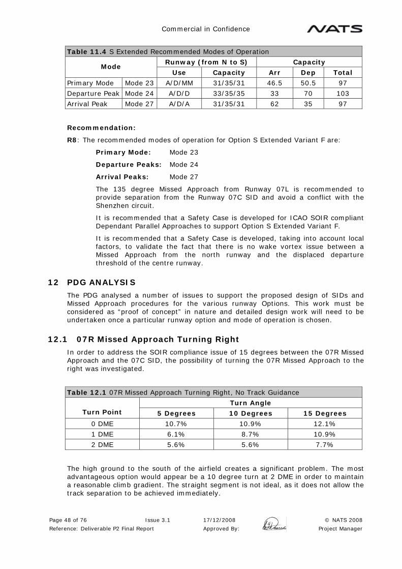
Commercial in Confidence
Page 48 of 76 Issue 3.1 17/12/2008 © NATS 2008
Reference: Deliverable P2 Final Report Approved By: Project Manager
Table 11.4 S Extended Recommended Modes of Operation
Runway (from N to S) Capacity Mode
Use Capacity Arr Dep Total
Primary Mode Mode 23 A/D/MM 31/35/31 46.5 50.5 97
Departure Peak Mode 24 A/D/D 33/35/35 33 70 103
Arrival Peak Mode 27 A/D/A 31/35/31 62 35 97
Recommendation:
R8: The recommended modes of operation for Option S Extended Variant F are:
Primary Mode: Mode 23
Departure Peaks: Mode 24
Arrival Peaks: Mode 27
The 135 degree Missed Approach from Runway 07L is recommended to provide separation from the Runway 07C SID and avoid a conflict with the Shenzhen circuit.
It is recommended that a Safety Case is developed for ICAO SOIR compliant Dependant Parallel Approaches to support Option S Extended Variant F.
It is recommended that a Safety Case is developed, taking into account local factors, to validate the fact that there is no wake vortex issue between a Missed Approach from the north runway and the displaced departure threshold of the centre runway.
12 PDG ANALYSIS
The PDG analysed a number of issues to support the proposed design of SIDs and Missed Approach procedures for the various runway Options. This work must be considered as “proof of concept” in nature and detailed design work will need to be undertaken once a particular runway option and mode of operation is chosen.
12.1 07R Missed Approach Turning Right
In order to address the SOIR compliance issue of 15 degrees between the 07R Missed Approach and the 07C SID, the possibility of turning the 07R Missed Approach to the right was investigated.
Table 12.1 07R Missed Approach Turning Right, No Track Guidance
Turn Angle Turn Point 5 Degrees 10 Degrees 15 Degrees
0 DME 10.7% 10.9% 12.1%
1 DME 6.1% 8.7% 10.9%
2 DME 5.6% 5.6% 7.7%
The high ground to the south of the airfield creates a significant problem. The most advantageous option would appear be a 10 degree turn at 2 DME in order to maintain a reasonable climb gradient. The straight segment is not ideal, as it does not allow the track separation to be achieved immediately.
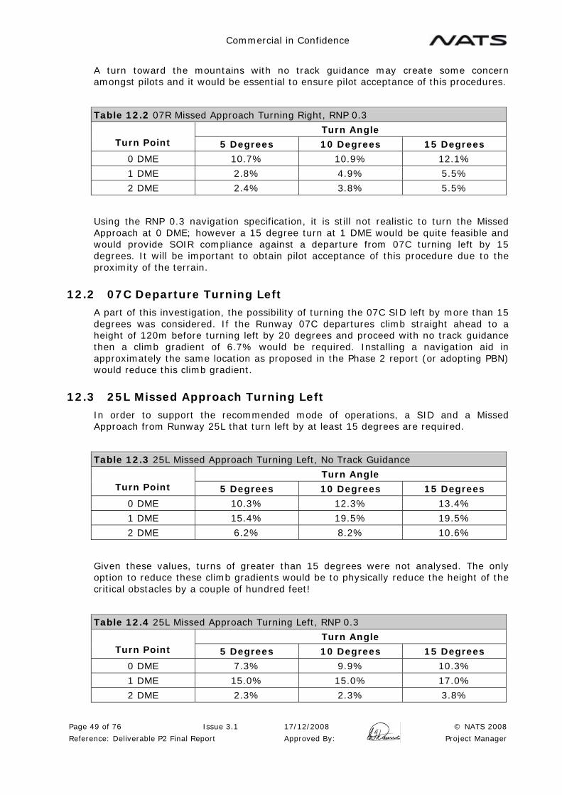
Commercial in Confidence
Page 49 of 76 Issue 3.1 17/12/2008 © NATS 2008
Reference: Deliverable P2 Final Report Approved By: Project Manager
A turn toward the mountains with no track guidance may create some concern amongst pilots and it would be essential to ensure pilot acceptance of this procedures.
Table 12.2 07R Missed Approach Turning Right, RNP 0.3
Turn Angle Turn Point 5 Degrees 10 Degrees 15 Degrees
0 DME 10.7% 10.9% 12.1%
1 DME 2.8% 4.9% 5.5%
2 DME 2.4% 3.8% 5.5%
Using the RNP 0.3 navigation specification, it is still not realistic to turn the Missed Approach at 0 DME; however a 15 degree turn at 1 DME would be quite feasible and would provide SOIR compliance against a departure from 07C turning left by 15 degrees. It will be important to obtain pilot acceptance of this procedure due to the proximity of the terrain.
12.2 07C Departure Turning Left
A part of this investigation, the possibility of turning the 07C SID left by more than 15 degrees was considered. If the Runway 07C departures climb straight ahead to a height of 120m before turning left by 20 degrees and proceed with no track guidance then a climb gradient of 6.7% would be required. Installing a navigation aid in approximately the same location as proposed in the Phase 2 report (or adopting PBN) would reduce this climb gradient.
12.3 25L Missed Approach Turning Left
In order to support the recommended mode of operations, a SID and a Missed Approach from Runway 25L that turn left by at least 15 degrees are required.
Table 12.3 25L Missed Approach Turning Left, No Track Guidance
Turn Angle Turn Point 5 Degrees 10 Degrees 15 Degrees
0 DME 10.3% 12.3% 13.4%
1 DME 15.4% 19.5% 19.5%
2 DME 6.2% 8.2% 10.6%
Given these values, turns of greater than 15 degrees were not analysed. The only option to reduce these climb gradients would be to physically reduce the height of the critical obstacles by a couple of hundred feet!
Table 12.4 25L Missed Approach Turning Left, RNP 0.3
Turn Angle Turn Point 5 Degrees 10 Degrees 15 Degrees
0 DME 7.3% 9.9% 10.3%
1 DME 15.0% 15.0% 17.0%
2 DME 2.3% 2.3% 3.8%

Commercial in Confidence
Page 50 of 76 Issue 3.1 17/12/2008 © NATS 2008
Reference: Deliverable P2 Final Report Approved By: Project Manager
A turn before 2 DME is unlikely to be acceptable due to the climb gradient and the proximity of the terrain. A 15 degree turn at 2 DME would appear to be the ideal solution. A turn of any more than 15 degrees would quickly increase the climb gradient even with RNP 0.3 navigation.
The straight segment is not ideal, as there is a period of parallel tracking with the SID (Note: In some Runway options the Runway 25C SID cannot turn right immediately due to the stagger of the north runway). It will also be important to obtain pilot acceptance of this procedure due to the proximity of the terrain.
12.4 25L SID Turning Left
A SID from Runway 25L turning left by 15 degrees was analysis in the Phase 2 report and requires a climb gradient is 3.3%.
12.5 15 degree Separation between SID and Missed Approach
The recommended modes of operation have been based on 15 degree separation between the Runway 07R Missed approach and the Runway 07C SID (less that the SOIR manual minimum of 30 degrees). This discussion is also relevant to establishing the appropriate separation between the Runway 25L Missed Approach and the Runway 25C SID.
Figure 12.1 SOIR Compliant Missed Approach and SID with 760m Runway Separation
Figure 12.1 illustrates the PANS-OPS protection areas for SOIR compliant Missed Approach and SID. A fictitious runway, 760m north of the existing Runway 07R/25L has been created and the protection criteria for the 30 degree SID for this runway superimposed on the Missed Approach criteria for Runway 07R. The nominal track is also shown for each procedure. These are the criteria with no track guidance, and

Commercial in Confidence
Page 51 of 76 Issue 3.1 17/12/2008 © NATS 2008
Reference: Deliverable P2 Final Report Approved By: Project Manager
these procedures are considered to be separated in terms of the SOIR criteria. It can be seen that these protection areas overlap substantially and, in the worst case, a departure subject to a strong northerly crosswind would overlap the track of a Missed Approach who was maintaining the Missed Approach nominal track.
Figure 12.2 Hong Kong Missed Approach and SID with 15 Degrees Separation, No Track Guidance
Figure 12.2 illustrates the proposed Runway 07R Missed approach and Runway 07C SID with no track guidance. This is clearly a significant improvement. The nominal tracks remain clear of the adjacent protection areas. Provided that at least one of the aircraft maintain the nominal track, then the protection area of the adjacent procedure is never infringed. As a cross wind is likely to affect both aircraft in the same direction, this is also likely to be acceptable. The main disadvantage of this procedure is that with the 15 degree tracks separation it takes substantially longer for an alternative separation (e.g. 3NM radar separation) to be established.
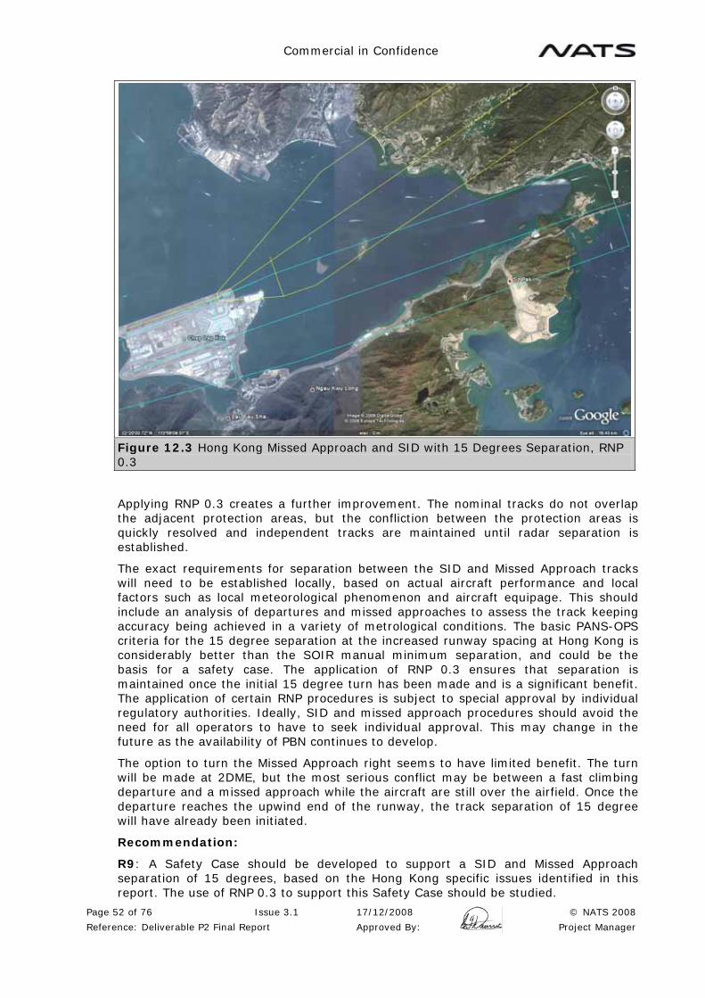
Commercial in Confidence
Page 52 of 76 Issue 3.1 17/12/2008 © NATS 2008
Reference: Deliverable P2 Final Report Approved By: Project Manager
Figure 12.3 Hong Kong Missed Approach and SID with 15 Degrees Separation, RNP 0.3
Applying RNP 0.3 creates a further improvement. The nominal tracks do not overlap the adjacent protection areas, but the confliction between the protection areas is quickly resolved and independent tracks are maintained until radar separation is established.
The exact requirements for separation between the SID and Missed Approach tracks will need to be established locally, based on actual aircraft performance and local factors such as local meteorological phenomenon and aircraft equipage. This should include an analysis of departures and missed approaches to assess the track keeping accuracy being achieved in a variety of metrological conditions. The basic PANS-OPS criteria for the 15 degree separation at the increased runway spacing at Hong Kong is considerably better than the SOIR manual minimum separation, and could be the basis for a safety case. The application of RNP 0.3 ensures that separation is maintained once the initial 15 degree turn has been made and is a significant benefit. The application of certain RNP procedures is subject to special approval by individual regulatory authorities. Ideally, SID and missed approach procedures should avoid the need for all operators to have to seek individual approval. This may change in the future as the availability of PBN continues to develop.
The option to turn the Missed Approach right seems to have limited benefit. The turn will be made at 2DME, but the most serious conflict may be between a fast climbing departure and a missed approach while the aircraft are still over the airfield. Once the departure reaches the upwind end of the runway, the track separation of 15 degree will have already been initiated.
Recommendation:
R9: A Safety Case should be developed to support a SID and Missed Approach separation of 15 degrees, based on the Hong Kong specific issues identified in this report. The use of RNP 0.3 to support this Safety Case should be studied.

Commercial in Confidence
Page 53 of 76 Issue 3.1 17/12/2008 © NATS 2008
Reference: Deliverable P2 Final Report Approved By: Project Manager
13 GROUND MANOUVERING ISSUES
13.1 Options P and R
The most significant issue noted with Option P is the taxiways that cross behind the Runway 07C threshold. Care is required in the design of these taxiways and the adjacent parallel taxiways, to ensure that they are clear of the obstacle clearance surfaces for the centre runway. In the Runway 07 direction, these taxiways offer a significant benefit, allowing aircraft to route behind the Runway 07C threshold and reducing the number of crossings of the centre runway.
In the Runway 25 direction the north/south elements of these taxiways are not separated from Runway 25C departures. As a result, movements on these taxiways count as a runway crossing and must be controlled as such. The aircraft will be cleared to a relevant holding point and then instructed to cross the runway in a suitable gap by the AMC controller. This creates a number of complications. Suitable runway holding positions must be marked on these taxiways. There is a risk that pilots familiar with crossing behind Runway 07C departures might fail to stop and create a runway incursion risk when Runway 25C is in use. There will be different procedures depending on the runway in use, either GMC on the existing airfield hands over directly to the GMC controller in Terminal 3 (Runway 07 Direction), or hands over to the AMC to cross the centre runway (Runway 25 direction), also creating the possibility for confusion. An alternative would be to close these taxiways when Runway 25C is in use and cross the centre runway at the upwind end.
The taxiways to the west of the Runway 07C threshold need to be far enough to the west to allow aircraft to taxiway independent of any arrivals and departures on the centre runway. The Obstacle Limitation Surfaces (OLS) slope of 2% commencing 60m from the threshold indicates that a Code F taxiway should be located around 1100m west of the 07C threshold. This may increase taxi distances by forcing aircraft to taxi to the west and the back to Terminal 3. It may be beneficial to investigate the possibility of relocating the terminal further to the west in order to resolve this problem. The east/west taxiways also have to be clear of the OLS, so these taxiways may have to be angled.
Figure 13.2 Option P OLS to the West of the Runway 07C Threshold
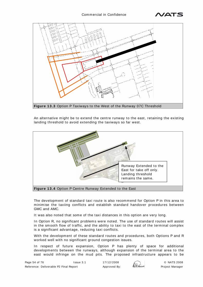
Commercial in Confidence
Page 54 of 76 Issue 3.1 17/12/2008 © NATS 2008
Reference: Deliverable P2 Final Report Approved By: Project Manager
Figure 13.3 Option P Taxiways to the West of the Runway 07C Threshold
An alternative might be to extend the centre runway to the east, retaining the existing landing threshold to avoid extending the taxiways so far west.
Figure 13.4 Option P Centre Runway Extended to the East
The development of standard taxi route is also recommend for Option P in this area to minimise the taxiing conflicts and establish standard handover procedures between GMC and AMC.
It was also noted that some of the taxi distances in this option are very long.
In Option R, no significant problems were noted. The use of standard routes will assist in the smooth flow of traffic, and the ability to taxi to the east of the terminal complex is a significant advantage, reducing taxi conflicts.
With the development of these standard routes and procedures, both Options P and R worked well with no significant ground congestion issues.
In respect of future expansion, Option P has plenty of space for additional developments between the runways, although expansion of the terminal area to the east would infringe on the mud pits. The proposed infrastructure appears to be
Runway Extended to the East for take off only. Landing threshold remains the same.

Commercial in Confidence
Page 55 of 76 Issue 3.1 17/12/2008 © NATS 2008
Reference: Deliverable P2 Final Report Approved By: Project Manager
adequate for the proposed level of aircraft movements. In Option R, the space between the runways is certainly adequate for the proposed operation and it appears that this could easily accommodate additional traffic. Further expansion to the east or west would be possible. Further expansion to the east may infringe on additional mud pits.
13.2 Option S Extended Variant F
In S Extended Variant F, take offs start from 950m displaced on 25C to provide separation from 25R Missed Approach. On Runway 07C, take offs start from the present position (950m from the new threshold) to provide separation from 07L Missed Approach.
Figure 13.5 Departure thresholds for S Extended Variant F
The design of RETs and crossing points is particularly important for closely spaced parallel runways. A RET leading directly to a crossing taxiway on an adjacent runway has been identified as a significant cause of runway incursions. Aircrew are frequently busy at this point completing after landing checks, changing frequency from AMC to GMC, and possibly referring to a map to check taxi instructions.
Figure 13.6 RETS and Crossing Points, Incorrect Design
Offsetting the crossings on the adjacent runway has been shown to improve crew situational awareness. It also provides other advantages, as an aircraft holding between the runways does not block the RET for subsequent landing traffic.
07
950m 950m
25
C
07 C
INCORRECT
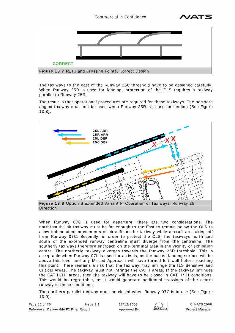
Commercial in Confidence
Page 56 of 76 Issue 3.1 17/12/2008 © NATS 2008
Reference: Deliverable P2 Final Report Approved By: Project Manager
Figure 13.7 RETS and Crossing Points, Correct Design
The taxiways to the east of the Runway 25C threshold have to be designed carefully. When Runway 25R is used for landing, protection of the OLS requires a taxiway parallel to Runway 25R.
The result is that operational procedures are required for these taxiways. The northern angled taxiway must not be used when Runway 25R is in use for landing (See Figure 13.8).
Figure 13.8 Option S Extended Variant F, Operation of Taxiways, Runway 25 Direction
When Runway 07C is used for departure, there are two considerations. The north/south link taxiway must be far enough to the East to remain below the OLS to allow independent movements of aircraft on the taxiway while aircraft are taking off from Runway 07C. Secondly, in order to protect the OLS, the taxiways north and south of the extended runway centreline must diverge from the centreline. The southerly taxiways therefore encroach on the terminal area in the vicinity of exhibition centre. The northerly taxiway diverges towards the Runway 25R threshold. This is acceptable when Runway 07L is used for arrivals, as the balked landing surface will be above this level and any Missed Approach will have turned left well before reaching this point. There remains a risk that the taxiway may infringe the ILS Sensitive and Critical Areas. The taxiway must not infringe the CAT I areas. If the taxiway infringes the CAT II/III areas, then the taxiway will have to be closed in CAT II/III conditions. This would be regrettable, as it would generate additional crossings of the centre runway in these conditions.
The northern parallel taxiway must be closed when Runway 07C is in use (See Figure 13.9).
CORRECT
x x x25L ARR 25R ARR 25L DEP 25C DEP

Commercial in Confidence
Page 57 of 76 Issue 3.1 17/12/2008 © NATS 2008
Reference: Deliverable P2 Final Report Approved By: Project Manager
The need to open and close taxiways dependant on runway direction could potentially create a risk of runway incursions, especially in poor visibility, and is generally undesirable. If Option S Extended Variant F is chosen, the ground marking, ATC and airfield operational procedures associated with the opening and closing of these taxiways need to be carefully designed to minimise workload and avoid the possibility of confusion.
Figure 13.9 Option S Extended Variant F, Operation of Taxiways, Runway 07 Direction
It can immediately be seen from the TAAM replays that Option S Extended Variant F requires the traffic to move through a much smaller taxiway infrastructure. In Options P and R, many movements in and out of Terminal 3 are contained within the new area of taxiways and do not have an effect on the existing airfield. In Option S Extended Variant F, many of these movements to and from Terminal 3 have to transit the existing airfield. This is most severe on the parallel taxiways north of Terminal 1.
Figure 13.10 Option S Extended Variant F, Taxiway A & B, Runway 07 Direction
x x
07R ARR 07L ARR 07R DEP 07C DEP
07R ARR 07L ARR 07R DEP 07C DEP
x x
x
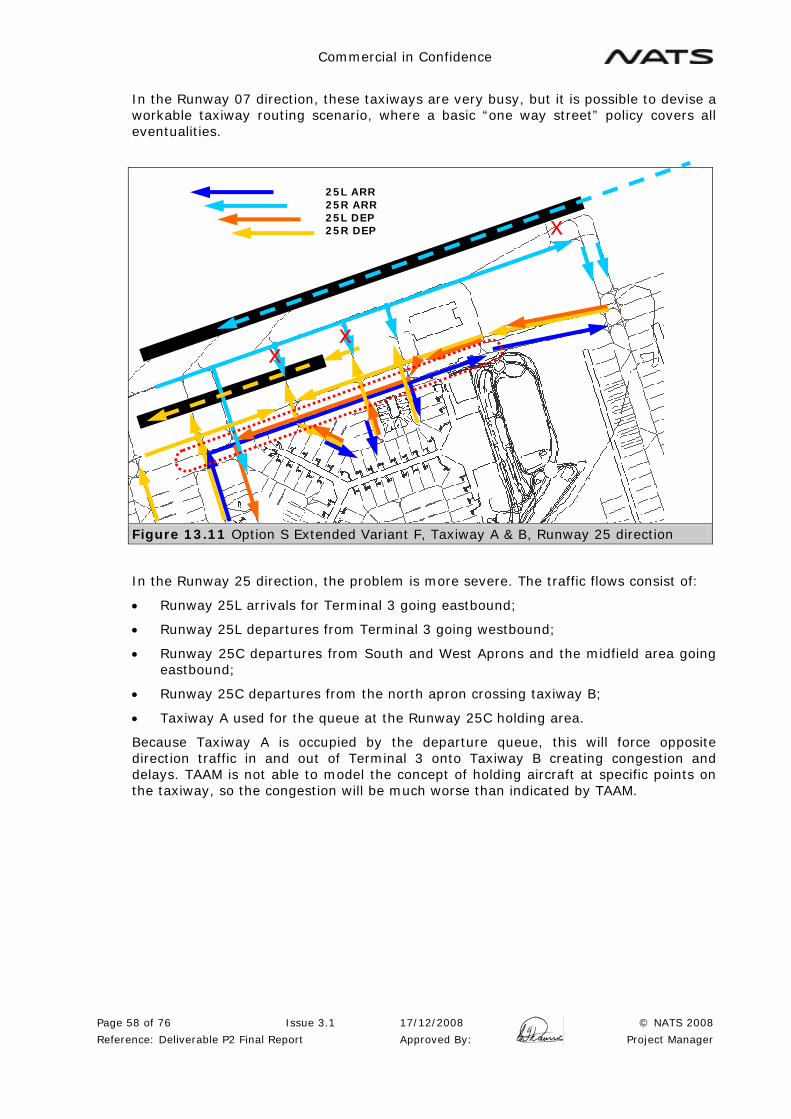
Commercial in Confidence
Page 58 of 76 Issue 3.1 17/12/2008 © NATS 2008
Reference: Deliverable P2 Final Report Approved By: Project Manager
In the Runway 07 direction, these taxiways are very busy, but it is possible to devise a workable taxiway routing scenario, where a basic “one way street” policy covers all eventualities.
Figure 13.11 Option S Extended Variant F, Taxiway A & B, Runway 25 direction
In the Runway 25 direction, the problem is more severe. The traffic flows consist of:
• Runway 25L arrivals for Terminal 3 going eastbound;
• Runway 25L departures from Terminal 3 going westbound;
• Runway 25C departures from South and West Aprons and the midfield area going eastbound;
• Runway 25C departures from the north apron crossing taxiway B;
• Taxiway A used for the queue at the Runway 25C holding area.
Because Taxiway A is occupied by the departure queue, this will force opposite direction traffic in and out of Terminal 3 onto Taxiway B creating congestion and delays. TAAM is not able to model the concept of holding aircraft at specific points on the taxiway, so the congestion will be much worse than indicated by TAAM.
25L ARR 25R ARR 25L DEP 25R DEP x
x x
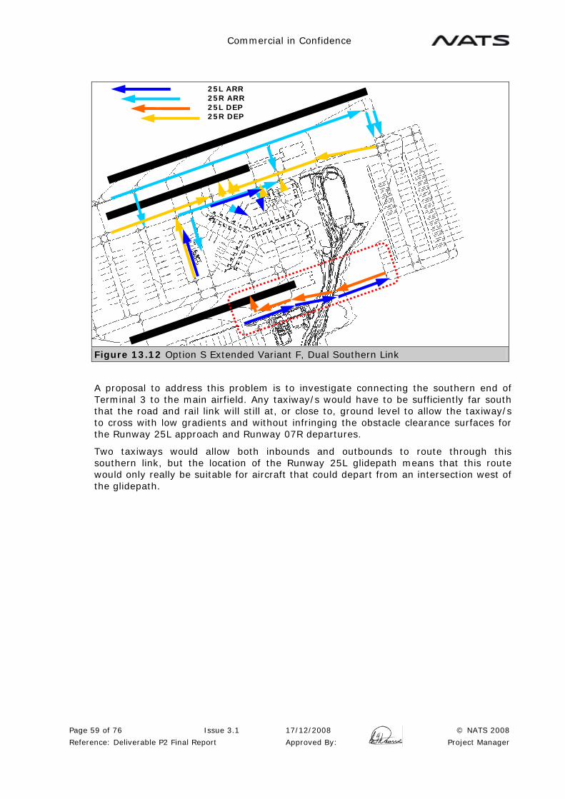
Commercial in Confidence
Page 59 of 76 Issue 3.1 17/12/2008 © NATS 2008
Reference: Deliverable P2 Final Report Approved By: Project Manager
Figure 13.12 Option S Extended Variant F, Dual Southern Link
A proposal to address this problem is to investigate connecting the southern end of Terminal 3 to the main airfield. Any taxiway/s would have to be sufficiently far south that the road and rail link will still at, or close to, ground level to allow the taxiway/s to cross with low gradients and without infringing the obstacle clearance surfaces for the Runway 25L approach and Runway 07R departures.
Two taxiways would allow both inbounds and outbounds to route through this southern link, but the location of the Runway 25L glidepath means that this route would only really be suitable for aircraft that could depart from an intersection west of the glidepath.
25L ARR 25R ARR 25L DEP 25R DEP

Commercial in Confidence
Page 60 of 76 Issue 3.1 17/12/2008 © NATS 2008
Reference: Deliverable P2 Final Report Approved By: Project Manager
Figure 13.13 Option S Extended Variant F, Single Southern Link
If it was only practical to build a single taxiway link, this would still have a considerable benefit by routing south runway arrivals to Terminal 3 without impinging on the existing airfield. There would still remain a head on confliction on Taxiway B between inbounds to the north apron and outbounds from Terminal 3.
The construction of new southern link taxiway/s appears to be required in order to make this option viable from an ATC perspective with an eastern terminal development. A further review and TAAM modelling should be undertaken to assess how the congestion can be relieved, to review the requirement for the southern link taxiway and to consider a western terminal location.
Option S Extended Variant F otherwise works, particularly in the Runway 07 direction and taxi distances are shorter than the other options.
S Extended Variant F has been expanded to what appears to be the limit of the existing airfield area and taxiway infrastructure. This will result in a very high intensity operation in a comparatively small space. Any further expansion would have to be to the west and north of the airfield. However, these areas are untouched by this development and would offer significant opportunities for expansion.
Recommendations:
R10: If Option S Extended Variant F is selected, a review should be undertaken to relieve the congestion north of the existing terminal building considering the addition of southern link taxiways and a western terminal location.
25L ARR 25R ARR 25L DEP 25R DEP

Commercial in Confidence
Page 61 of 76 Issue 3.1 17/12/2008 © NATS 2008
Reference: Deliverable P2 Final Report Approved By: Project Manager
13.3 Runway Crossings
A detailed analysis of the number of runway crossing has been undertaken and the results are provided in Appendix D. A summary of the results are given here.
In a three runway airport, it is unrealistic to expect that crossings of the centre runway can be avoided at all times. Design of taxiway/s behind the centre runway thresholds can reduce the number of crossings, depending on the airfield configuration.
There is no absolute limit on the number of crossings that can be accommodated safely. This will depend on local circumstances. For example, crossing a departure runway is preferable to crossing an arrival runway, and in the case of Hong Kong, the 90 second departure interval should allow crossings to take place without significantly impacting the departure rate. This means that modes of operation where the centre runway is the departure runway are preferred. However, once the number of crossing reaches a critical number, the need to cross more than one aircraft in one gap, or the resulting queues of aircraft waiting to cross, can impact on the overall operation of the airfield and have an impact on capacity.
NATS experience indicates that an average number of crossings of up to 15 per hour, with peaks up to 20 per hour, could be used as a baseline for the number of crossings that could comfortably be accommodated. However, there are many airports that operate with much higher number of crossings. Using this baseline, the following conclusions can be drawn from the analysis of ground operations and runway crossings.
Terminal Arrivals/Compass Departures has a lower number of crossings than Compass Arrivals/Compass Departures, although this difference is much less significant in Option S Extended Variant F, due to the ability of north runway traffic to enter Terminal 3 without a runway crossing. In Option P the Runway 07 direction has less crossings than the Runway 25 direction due to the taxiway behind the Runway 07C threshold. It is recommended that this taxiway is designed to avoid runway crossings in the Runway 25 direction.
00 03 06 09 12 15 18 21 000
5
10
15
20
25
30
35
40
45
Option P Runway Crossings
Runway 07 TC Runway 07 CC Runway 25 TC Runway 25 CC
Figure 13.14 Option P Terminal Arrival/Compass Departure (TC) Compared to Compass Arrival/Compass Departure (CC). Runway 07 Compared to Runway 25

Commercial in Confidence
Page 62 of 76 Issue 3.1 17/12/2008 © NATS 2008
Reference: Deliverable P2 Final Report Approved By: Project Manager
Mode 23 has a slightly higher number of crossings than Mode 9, but this varies for each configuration. A significant problem with the airfield and mode of operations is that the majority of stands are in Terminal 1 and the midfield, yet in Mode 23, the majority of landings are on the north runway. This, together with departures from Terminal 3 for the south runway, creates a large number of crossings of the centre runway.
00 03 06 09 12 15 18 21 000
5
10
15
20
25
30
35
40
45
Option P Mode 23 v Mode 09
Runway 25 TC Mode 09 Runway 25 TC Mode 23
Figure 13.15 Runway Crossings - Option P Mode 9 Compared to Mode 23 (Runway 25 Terminal Arrivals/Compass Departures)
Option R has no difference between the Runway 25 and Runway 07 direction. Option S Extended S Variant F has less crossings in the Runway 25 direction, as more traffic is able to use the taxiway behind the Runway 25C threshold to enter Terminal 1.
Option R cannot be recommended unless taxiways are introduced to taxi behind the centre runway thresholds. These would be used according to the runway direction at the departure end of the runway and the taxiway at the upwind end would be closed. However, these taxiways substantially increase taxi distances, and in the Runway 25 direction create a serious congestion issue on Taxiways A and B north of the existing terminal.
Figure 13.16 Option R Possible Taxiways Behind Centre Runway Threshold
Used in Runway 07 Direction only.
Used in Runway 25 Direction only.
Commercial in Confidence
Page 63 of 76 Issue 3.1 17/12/2008 © NATS 2008
Reference: Deliverable P2 Final Report Approved By: Project Manager
Option P requires the cross taxiways behind the Runway 07C threshold to be available in both runway directions. In Option S Extended Variant F the number of crossings of the centre runway is considered to be acceptable, subject to real time simulations.
14 TAAM WORK
TAAM modelling has been employed to provide support to some areas of the analysis of the modes of operation for the two runway and three runway airport
The scope of the TAAM work package includes the following:
• Modelling of Hong Kong International Airport with 2 runways operating in a reorganized PRD airspace;
• Modelling of the 3 third runway options (P/R/SX) from Phase 2 to:
o Investigate the mode of runway operations (Mode 9 versus Mode 23);
o Investigate the mode of arrival operations (Compass versus Terminal);
o Investigate feasibility of airborne crossover tracks for arrivals and departures;
o Investigate some aspects of ground operations in the various modes of operations;
Full details of the TAAM work can be found in Appendix D. Replays of the various options have been provided together with numerical analysis covering the following areas:
• Average arrival taxi times undelayed/delayed;
• Average departure taxi times undelayed/delayed;
• Average runway holding zone (RHZ) delay for departures;
• Number of runway crossings;
• Crossfield taxiway usage;
• T3 link taxiway usage for Option S Extended;
• Delay incurred on Taxiways A/B for Option S Extended;
These numbers have been deduced and summed in various ways (by apron, by hour, by runway, by taxiway etc).
An analysis of runway crossings can be found in the Runway Crossings section above. A summary of other points noted from the analysis is provided here. See Appendix D for full details.
The taxi times for both arrivals and departures in Terminal Arrivals/Compass Departures are less that in Compass Arrivals/Compass Departures. The differences vary according to the runway direction and the mode of operations. For options R and S Extended Variant F the differences are minimal.

Commercial in Confidence
Page 64 of 76 Issue 3.1 17/12/2008 © NATS 2008
Reference: Deliverable P2 Final Report Approved By: Project Manager
Average Arrival Taxi Times Option PRunway 25 Mode 09 Compass Arrivals/Terminal Arrivals
0
300
600
900
1200
CM
F/E
MF/
W N ST3/X
1T3/X
2T3/X
3T3/Y
1T3/Y
2 W CM
F/E
MF/
W N ST3/X
1T3/X
2T3/X
3T3/Y
1T3/Y
2 W CM
F/E
MF/
W N ST3/X
1T3/X
2T3/X
3T3/Y
1T3/Y
2 W
25L 25R TOT
Seco
nds
Terminal Arrivals Compass Arrivals
Figure 13.17 Option P Mode 9 comparing Terminal Arrivals and Compass Arrivals
The taxi times for both arrivals and departures are longer for the Runway 25 directions rather than the Runway 07 direction.
Average Arrival Taxi Times Option R Mode 23Terminal Arrivals
0
300
600
900
1200
1500
CM
F/E
MF/
W N ST3/X
1T3/X
23
T3/X
4T3/Y
1T3/Y
2 W CM
F/E
MF/
W N ST3/X
1T3/X
23
T3/X
4T3/Y
1T3/Y
2 W CM
F/E
MF/
W N ST3/X
1T3/X
23
T3/X
4T3/Y
1T3/Y
2 W
07L 07R TOT
Seco
nds
Runway 07 Runway 25
Figure 13.18 Option R Mode 23 comparing Runway 07 and Runway 25
When comparing the Runway Holding Zone (RHZ) delays, Mode 23 has longer delays than Mode 9.

Commercial in Confidence
Page 65 of 76 Issue 3.1 17/12/2008 © NATS 2008
Reference: Deliverable P2 Final Report Approved By: Project Manager
Average RHZ Delay Option R Runway 25Terminal Arrivals / Compass Departures
0
300
600
900
1200
1500
1800
2100
00 03 06 09 12 15 18 21
Seco
nds
Mode 23 Mode 09
Figure 13.18 Option R Runway 25 comparing Mode 9 and Mode 23.
Recommendations:
R11: It is recommended that the LEAPP/AirBiz traffic forecasts and busy day schedules be updated again:
• to include original/destination information to allow accurate assessment of stand and runway demand and the mode of runway operations (terminal vs compass mode);
• to include a 2030 scenario;
R12: Develop a stand/terminal utilization plan taking into account availability of future development including the midfield area and the new terminal, preferably in conjunction with airline users;
R13: Rerun these simulation scenarios once:
• A proper ground layout has been designed;
• The traffic forecasts and busy day schedules have been updated;
• A stand/terminal utilization plan for the future has been developed;
in order to reassess more accurately the ground operations based on the most up-to-date information.
15 AIRBORNE CROSSOVERS
In an ideal world, all aircraft arriving and departing from the north would use a northerly runway and southerly traffic would use a southerly runway, so avoiding any problems associated with crossing traffic in the air. Unfortunately, this can never be totally achieved, although the nature of the crossover problems will depend on the runway option selected and particularly on the choice of compass or terminal modes.
Commercial in Confidence
Page 66 of 76 Issue 3.1 17/12/2008 © NATS 2008
Reference: Deliverable P2 Final Report Approved By: Project Manager
From the airborne point of view, compass arrivals and departures are preferable. Crossing issues are minimised, but some crossovers will be required to balance traffic between the runways. This mode places all the crossover issues on the ground and is likely to increase ground congestion and taxi distances.
In Terminal mode, a much larger number of crossovers are inevitable, but this can be mitigated to some degree by terminal occupancy (e.g. airlines which only serve destination to the north use the northern terminal). Placing the crossovers in the air increases the complexity of the TMA and approach environment, and may increase flying times and distances.
The actual choice of terminal or compass modes of operation requires a detailed study including, as a minimum, the chosen runway option, taxiway infrastructure, terminal occupancy and anticipated schedule. The outcome is likely to be composite of both modes designed to best meet the local requirements at HKIA and will inevitably have to be a compromise that balances the airline and airport preferences for terminal and stand occupancy and the operational issues concerning ground congestion, taxing distance and airborne crossovers and track distances flown.
The allocation of runways and crossovers needs, as far as possible, to be based on a simple set of rules that can be applied in a straightforward manner. The runway allocation and any associated crossover needs to be made well in advance of the aircraft’s landing time (e.g. around 30 minutes). This will require a suitable arrival management tool that can apply the runway allocation rules and balance the runway demand, both inbound and outbound. The information is required by all relevant controllers (Approach, TMA and En-route) so that the crew can be advised of the runway and any route change well in advance. This may require the arrival management system to be integrated into all the ATC systems in the PRD airspace, both Hong Kong and mainland China.
It is possible for airborne crossovers to generally be considered in two categories, close to the airfield and far from the airfield.
In the case of arrivals, crossovers on final approach are possible. Provided that 1000ft vertical separation is maintained, then an aircraft from the north can establish on the south runway, and the reverse is also true. This is likely to take place at around 20NM final, before commencing decent on the glidepath. This type of crossover creates significant workload for FAD and so is unlikely to be suitable for frequently crossovers. It should be included in APP and FAD training to accommodate short notice changes.
Arrival crossovers far from the airfield are accomplished in two ways, before and after the holding stack. By identifying aircraft requiring a crossover at an early stage, the aircraft is then routed to a holding stack on the other side of the airfield, where it can join the inbound route from that stack onto the desired runway. In order to avoid complications in the approach sector, this crossover should take place at a higher level. The use of standard levels for the crossovers simplifies procedures for the TMA controllers and allows the standard level to be kept free in the receiving stack to accept the crossover traffic.
With the runway allocation known well in advance, an alternative crossover strategy may be appropriate in some cases. Where possible, the crossover should take place before the holding stack. This can move some of the workload from TMA to en-route, which may be beneficial. A re-route at high level can also be more efficient by reducing track mileage and flying time and giving the crew time to plan the approach.
This concept can be extended further to the idea of flight planning to the desired runway. Although the flight plan system does not officially support flight planning to a specific runway, there are techniques that can achieve this objective. By publishing STARs to accommodate crossing traffic (e.g. a STAR from the north to a southern holding stack), this STAR can be included in the flight plan and the flight data processing system can recognise this as an aircraft which intends to land on the south

Commercial in Confidence
Page 67 of 76 Issue 3.1 17/12/2008 © NATS 2008
Reference: Deliverable P2 Final Report Approved By: Project Manager
runway. Flight planning in this way has considerable advantages. It provides advanced planning information for ATC. For the crew it allows the arrival to be programmed into the FMS prior to departure, providing a level of certainty as to the arrival route and the descent profile to be planned. Optimising the whole flight planned route to the expected arrival profile may allow the crossover penalties to be minimised. There will still be a need for some unplanned crossovers for runway balancing, but these are minimised.
Departure crossovers need to be accomplished as soon as possible in order to minimise any track distance penalties. Departure crossovers will need standard routes and levels to simplify the crossover process and ensure separation from other departing and arriving aircraft. The differences in aircraft performance need to be considered but sometimes it is inevitable that aircraft have to maintain an intermediate altitude for some time during the crossover.
16 SCHEDULING AND CAPACITY DECLARATION
16.1 Hourly Capacity
The assessment and declaration of capacity and schedule limits becomes more complex with the three runway airport. The preferred mode of operations (Mode 23) provides a north runway with 33/36* arrivals per hour (ideally from the north), a centre runway with 35 departures, preferably northbounds, and a mixed mode south runway with 17 arrivals and 17 departures, preferably to and from the south, so achieving the potential capacity of 102 movements per hour (*or up to 105 movements per hour with the reduction in contingency in arrival spacing). In any hour when the balance of northbounds and southbounds varies then, as a minimum, ground or airborne crossovers are required. Maintaining the capacity requires this to be achieved efficiently, delivering the aircraft to the runway at the optimal time, taking into account the increased flight or taxi times. If at any time the supply of aircraft at the runway or airborne hold becomes exhausted, the available runway capacity is wasted. When adjusting the runway usage for arrival or departure peaks, both arrivals and departure demand must be tailored to the new situation and suitably balanced to ensure that capacity is used efficiently. E.g. a departure peak ideally requires 35 northbound departures from the centre runway and 35 southbound departures from the south runway together with 33/36* arrivals. Other combinations are possible, but the complexity increases (e.g. the south runway capacity used for two thirds arrivals and one third departures). In some ways the new airport is more oriented towards northbound traffic. Existing Mainland China plus other BEKOL and DOTMI traffic is northbound in the new operation. Potentially other traffic such as Taipei, Japan and Pacific oceanic traffic could also use northbound routes, but would require Chinese Mainland overflying rights.
This requires close attention to the scheduling to ensure that the traffic flows are balanced throughout the hour, and throughout the day. The NATS Phase 1 capacity study recommended that capacity declaration should be on an hourly basis. For the three runway airport, there may be benefits in looking at shorter periods, (e.g. 30 minutes or 15 minutes) within the hour to balance demand throughout the hour. There are also benefits in looking at specific flights. E.g. if a Terminal 1 based flight is arriving from the north and departing to the south, then it may be beneficial to accept an airborne crossover to land on the south runway. This would provide a short taxi to the south apron, and then a short taxi for the subsequent departure back to the south runway. The overall schedule will need to take into account the runway option selected, the terminal occupancy and stand allocation strategy, the taxiway infrastructure and will inevitably be a compromise between airborne crossovers/flight times and ground congestion/taxi times.

Commercial in Confidence
Page 68 of 76 Issue 3.1 17/12/2008 © NATS 2008
Reference: Deliverable P2 Final Report Approved By: Project Manager
Overall, while the maximum potentially capacity is 102 movements per hour (*or up to 105 with the reduction in contingency in arrival spacing), in non-optimum hours an allowance needs to be made for the fact that there will be some wasted capacity. NATS experience indicates that this allowance should be in the order to 10% to 20%.
Recommendation:
R14: A further study is undertaken into the detailed modes of operation (compass or terminal modes) and the associated issues including capacity and the need to minimize any capacity wastage.
16.2 Annual Capacity
The NATS Phase 2 report assessed the annual capacity of a three runway airport, based on a maximum potential hourly figure of 102 movements. This estimated that a daily capacity in the range 1650 to 1800 movements is achievable, depending on factors such as the contingency allowance chosen for runway direction changes and recovery periods. Using the Design Day/Annual ratio of 0.0029 supplied by AAHK, this would provide an annual capacity in the range of 570,934 to 622,837.
A reduction in the contingency in arrival spacing could increase capacity up to around 105 movements per hour. Using the same calculation as above, this could potentially increase the daily capacity to around 1700 to 1850 movements per day with an annual capacity in the range.588,235 to 640,138. This would, however, assume that there was demand for this increased arrival rate throughout the day. Taking this into account, together with the need to allow for some capacity wastage when the scheduled demand does not exactly match the available runway capacity, this would suggest that the achievable schedule limit would be in the range 1500 (1650 less approximately 10%, or 1850 less approximately 20%) to 1700 (1850 less approximately 10%) and an annual capacity in the range 519,031 to 588,235.
The review of the modes of operation (see Recommendation R14) should include an assessment of the capacity wastage to enable the daily and annual capacity figures to be verified.
The NATS Phase 1 study assessed the daily capacity of the two runway airport in the range 1100 to 1200 movements per day and the annual capacity in the range of 379,310 to 413,793 (based on 68 movements per hour). In PRD airspace, a reduction in the contingency in arrival spacing could increase capacity up to around 71 movements per hour. Using the same calculation as above, this could potentially increase the daily capacity to around 1150 to 1250 movements per day. This would, however, assume that there was demand for this increased arrival rate throughout the day. To take a more realistic approach, assuming this demand was taken up for 12 hours per day, then the increase would be limited to about 36 per day. This results in the estimated daily capacity being in the range 1136 to 1236 movements. Using the Design Day/Annual ratio of 0.0029 supplied by AAHK, this would provide an annual capacity in the range of 393,080 to 427,682.
17 SAFEGUARDING FOR FUTURE ROUTES
It is understood that the current Airport Height Restriction Plan (AHRP) safeguards the airspace within Hong Kong's territorial border based on the procedures devised in 1996 for the current 2-runway airport.
The proposed SIDs, STARs and Missed Approach Procedures for a 3-runway Hong Kong International Airport will overfly some areas of Hong Kong where there are currently no overflying air traffic routes and are therefore not included in the current safeguarding plan. Given the speed and scale of property developments in Hong Kong, it is essential to add additional safeguards to these affected areas. This should be

Commercial in Confidence
Page 69 of 76 Issue 3.1 17/12/2008 © NATS 2008
Reference: Deliverable P2 Final Report Approved By: Project Manager
done as soon as a one of the third runway options have been chosen and the associated ATC procedures are designed.
Areas potentially affected include:
• Areas along the approach path to the third runway in both 07 and 25 directions (for at least 20NM);
• Areas from the Goldcoast development along Tai Lam valley towards northeastern New Territories where a new northbound SID will be introduced;
• Areas along Tuen Mun valley where a new SID or missed approach may be introduced for Options P and R;
• Northwestern New Territories where a missed approach track may be routed to rejoin the northern downwind;
• Southwestern Lantau Island where the new 25L departure track and missed approach will turn left immediately after departure, instead of travelling straight ahead;
Preparation for the amendment of the current AHRP must begin as soon as practicable given the length of the design and legal processes and potential petitions and objections.
Consideration must also be given to relocate danger area VHD5 due to the potential impact of SIDs and Missed Approach procedures in the vicinity.
Recommendations:
R15: Initiate the necessary process to safeguard additional areas in Hong Kong for future flight routes as soon as practicable.
R16: Initiate the necessary process to relocate danger area VHD5.
18 INTERACTIONS WITH ADJACENT AIRFIELDS
18.1 Macau
There is an interaction with Macau in respect of Hong Kong departure traffic in the Runway 25 direction and for Hong Kong landing traffic in the Runway 07 direction.
18.1.1 2 Runways Operating in Segregated Mode
The existing SIDs from Runway 25L and 25R do not interact with Macau. Steps that would increase the capacity of the 2 runway airport in segregated mode would only involve arriving traffic and the existing SIDs would be unchanged.
As previously discussed in the section on Stage 1 (2 Runways) above, extending the Runway 07 final into the existing Macau airspace prior to the full implementation of PRD airspace is not recommended. Once the full PRD airspace is available, a long final can be provided with a north and south circuit and traffic joining the final approach from both sides. A 16-18NM final is likely to be required for the 3 runway operation. Although this length of final is not required in segregated mode, it is recommended that it is introduced at this stage. This will avoid the need for changes at a later date, offer maximum flexibility for vectoring allowing consistent spacing to be achieved and provide experience of the long final.
18.1.2 2 Runways Operating in Mixed Mode and 3 Runways
The operation of 2 Runways in Mixed Mode and 3 Runways will involve parallel approaches to HKIA. Although the change to mixed mode on 2 runways has not been
Commercial in Confidence
Page 70 of 76 Issue 3.1 17/12/2008 © NATS 2008
Reference: Deliverable P2 Final Report Approved By: Project Manager
recommended, the airspace issues for these scenarios do not differ significantly. Once the independent or dependant approach procedures have been developed (depending on the runways being used), north and south circuits must be operated with separate Approach and FAD controllers. A high side and a low side are required, the high side of 5000ft indicating that a final of at least 16NM final is required in the Runway 07 direction, but to allow scope for vectoring, a minimum of 20NM is recommended.
Independent northbound and southbound departure routes are also required, supported by the wider re-organisation of the PRD airspace. This reorganisation must ensure that the Hong Kong arrival and departure routes are separated from the Macau traffic and is likely to involve associated revised Macau inbound and outbound routes. It is recommended that these are designed from the outset to accommodate the procedures for the selected third runway option, even if this is more restrictive than required for 2 runways, to avoid the need for later changes.
18.2 Shenzhen
The implementation of the north circuit will need to be integrated with the Shenzhen traffic. In particular, the possible conflict between the Hong Kong Runway 07L Missed Approach and the Shenzhen circuit needs to be resolved. The 135 degree Missed Approach from Runway 07 has been recommended to address this problem, but also needs to be considered from the flyability point of view due to the proximity of Castle Peak. The Runway 25R Missed Approach also needs to be considered, but the integration is more straightforward.
Hong Kong northbound departures also need to be considered and this integration is easier in the Runway 07 direction. The northbound SID in the Runway 25 direction needs to carefully simulated to ensure that is suitably integrated with Shenzhen traffic. Because this area is so complex, suitable buffer zones and direct controller to controller communication will be required to manage this airspace.
18.3 TMA operations
The development of a north circuit and the associated revised Macau and Shenzhen procedures need to be supported by a TMA style operation within the PRD airspace and the HK FIR. This should cover departure routes, arrival routes and holding facilities for Hong Kong to support the desired traffic levels together with facilities to support the existing and anticipated traffic levels at the adjacent airfields. It will be important to develop an integrated TMA operation for Macau, Shenzhen and Zhuhai in conjunction with the changes at HKIA in order to ensure that the capacity benefits can be achieved and a safe and orderly operation is maintained throughout the area.
19 IMPLEMENTATION PLAN
The full implementation plan to extend the systemised concept of operations into the PRD South airspace needs to be developed in consultation with the surrounding authorities, and this is outside the scope of this study. The structure of the plan will depend on the outcome of these discussion and the timescales and priorities identified in this process, including the timescales for the third runway. This section of the report describes basic principles that should be taken into account during the development of this plan.
The implementation plan will need routing and sectorisation designed to meet the needs of all stakeholders, taking into account the continuing development of the airfields in the region. It must address the equipment, staffing and training requirements of all the stakeholders in particular the need for integrated equipment and procedures due to the complex nature of the environment and the many interactions between the various airfields and control facilities. It will also require

Commercial in Confidence
Page 71 of 76 Issue 3.1 17/12/2008 © NATS 2008
Reference: Deliverable P2 Final Report Approved By: Project Manager
regulatory approval by all the relevant authorities. This plan will also include fast and real time simulations and an operational evaluation process involving all parties.
The plan will require consideration of the number of runways (two or three runways) and the planned operations (mixed mode or segregated mode) at HKIA. Depending on the anticipated length of time between the PRD airspace implementation and the opening of the third runway, there may be a desire to stage the implementation to initially support the capacity of the two runway airport, increasing to the three runway capacity at a later date.
To support two runways in segregated mode, it is anticipated that north and south circuits will be present, supported by separate approach controllers and a single FAD. With two runways in mixed mode, or three runways, two FAD positions will be required, and for Independent Parallel Approaches monitoring controllers may also be required.
The appropriate equipment will be required to support these operations. As minimum, this will require an arrival manager to support the holding stacks, arrival runway allocations and parallel approaches. In the three runway operations, it is recommended that this is integrated with a departure manager tool to assist with runway balancing and to allow departure runways to be allocated in the delivery position.
The requirements for the control tower need to be reviewed for each runway option. In the case of Option S Extended Variant F, any review of the existing control tower will need to assess the ability of the tower cab to accommodate the additional positions required for the third runway and Terminal 3. The design of the terminal will need to ensure that suitable sightlines are maintained to the stands and taxiways in Terminal 3. In the case of Options P and R, the distance from the existing tower to the far runway thresholds is much greater than would be desirable. In addition, the existing tower would probably have to be higher to achieve suitable sightlines to the holding areas of the northern runway and Terminal 3. It is therefore likely that a new control tower will be required in the vicinity of Terminal 3. The sightlines for the new terminal must be based on this tower. There will also be the need for robust coordination procedures between the two control towers, with particular care given to the procedures for coordination between the towers across the centre runway. Ideally, the same GMC controller should control the taxiways on both sides of the runway, otherwise standard routes and procedures must be strictly adhered to. It would also be highly desirable for the AMC and adjacent GMC controller/s to be sitting physically close together to allow immediate coordination of runway related issues. Operating with two control towers also requires a review of staffing to ensure that appropriate supervisory and support staff are provided in both towers and the requirements for fatigue breaks are covered. Requirements for the meteorological office and associated equipment must also be included.
The airspace design and ATC control facilities should be designed to support the maximum capacity of the three runway airport, together with the planned capacity increases at other PRD airfields in the time period. As the two runway capacity is lower, there is the possibility that a reduced number of positions will be able to handle this level of traffic. Fast time and real time simulations will need to be undertaken covering each stage of the implementation to assess the traffic loading and number of positions required. Ideally, a staged approach would be implemented where combined sectors are created (e.g. TMA high and low or TMA NE and TMA NW) and operated as one sector, but with the plan already established to split the sectors as traffic levels increase. In some cases training may be required to operate the sectors in split configuration, and this extension training needs to be allowed for in the plan and associated timescales.
Recommendation

Commercial in Confidence
Page 72 of 76 Issue 3.1 17/12/2008 © NATS 2008
Reference: Deliverable P2 Final Report Approved By: Project Manager
R17: An implementation plan should include all relevant aspects of the operation including staff, equipment and training, including an assessment of the planned operation (e.g. number of runways, mode of operations and any staged implementation). Equipment requirements would include facilities such as a new control tower and other supporting equipment.
20 RECOMMENDATIONS
R1: Once PRD Airspace has been implemented, this will improve the consistency of final approach spacing and allow the contingency allowance in the final approach spacing to be reduced or removed and the arrival rate to be increased.
R2: Once PRD Airspace has been implemented the introduction of NATS style spacing at the two runway airport in segregated mode (supported by a suitable training program and safety case) is recommended to further improve the arrival flow.
R3: The operation of the existing runways in Mixed Mode does not deliver a capacity increase and, due to the training and infrastructure changes required, this mode of operations is not recommended.
R4: The design of a long final in the Runway 07 direction, prior to the introduction of PRD airspace re-organisation, is not recommended.
R5: The recommended modes of operation for Options P and R are:
Primary Mode: Mode 23
Departure Peaks: Mode 24
Arrival Peaks: Mode 27
The 135 degree Missed Approach from Runway 07L is recommended to provide separation from the Runway 07C SID and avoid a conflict with the Shenzhen circuit.
It is recommended that a Safety Case should be developed for Independent Parallel Approaches based on the Hong Kong specific criteria identified in this report to support Options P and R.
R6: Option S Extended Variant F is adopted as the baseline version of Option S Extended and that consideration of the various terminal configurations is based on Variant F.
R7: Option S Extended Variants A to E inclusive are not recommended for further development.
R8: The recommended modes of operation for Option S Extended Variant F are:
Primary Mode: Mode 23
Departure Peaks: Mode 24
Arrival Peaks: Mode 27
The 135 degree Missed Approach from Runway 07L is recommended to provide separation from the Runway 07C SID and avoid a conflict with the Shenzhen circuit.
It is recommended that a Safety Case is developed for ICAO SOIR compliant Dependant Parallel Approaches to support Option S Extended Variant F.
It is recommended that a Safety Case is developed, taking into account local factors, to validate the fact that there is no wake vortex issue between a Missed Approach from the north runway and the displaced departure threshold of the centre runway.

Commercial in Confidence
Page 73 of 76 Issue 3.1 17/12/2008 © NATS 2008
Reference: Deliverable P2 Final Report Approved By: Project Manager
R9: A Safety Case should be developed to support a SID and Missed Approach separation of 15 degrees, based on the Hong Kong specific issues identified in this report. The use of RNP 0.3 to support this Safety Case should be studied.
R10: If Option S Extended Variant F is selected, a review should be undertaken to relieve the congestion north of the existing terminal building considering the addition of southern link taxiways and a western terminal location.
R11: It is recommended that the LEAPP/AirBiz traffic forecasts and busy day schedules be updated again:
• to include original/destination information to allow accurate assessment of stand and runway demand and the mode of runway operations (terminal vs compass mode);
• to include a 2030 scenario;
R12: Develop a stand/terminal utilization plan taking into account availability of future development including the midfield area and the new terminal, preferably in conjunction with airline users;
R13: Rerun these simulation scenarios once:
• A proper ground layout has been designed;
• The traffic forecasts and busy day schedules have been updated;
• A stand/terminal utilization plan for the future has been developed;
in order to reassess more accurately the ground operations based on the most up-to-date information.
R14: A further study is undertaken into the detailed modes of operation (compass or terminal modes) and the associated issues including capacity and the need to minimize any capacity wastage.
R15: Initiate the necessary process to safeguard additional areas in Hong Kong for future flight routes as soon as practicable.
R16: Initiate the necessary process to relocate danger area VHD5.
R17: An implementation plan should include all relevant aspects of the operation including staff, equipment and training, including an assessment of the planned operation (e.g. number of runways, mode of operations and any staged implementation). Equipment requirements would include facilities such as a new control tower and other supporting equipment.
21 CONCLUSIONS
The analysis of the ILS performance has confirmed that each localiser course conforms to Annex 10 requirements out to 20NM from touchdown. The glidepath has not yet been assessed due to the lack of flight check data.
The analysis of independent parallel approaches in terms of the ILS performance was undertaken for the three runway options (including variants). The wide spaced options can support independent parallel approaches using the SOIR manual example and Annex 10 criteria. Only one case was identified where the approaches could not be supported and this was Runway 25C and Runway 25R in Option R. This is the most closely spaced runway pair evaluated. This can be mitigated most easily by changing the mode of operation with Runway 25L and Runway 25R for landing.
The SOIR compliant breakout, a vertical breakout manoeuvre, and a breakout manoeuvre involving turning the blundering aircraft were all examined. The SOIR compliant breakout and the vertical breakout are not considered to be appropriate at HKIA and the breakout involving turning the blundering aircraft is recommended. The

Commercial in Confidence
Page 74 of 76 Issue 3.1 17/12/2008 © NATS 2008
Reference: Deliverable P2 Final Report Approved By: Project Manager
ILS analysis was applied to this breakout and indicates that it can be supported by the wide spaced options P and R. This breakout manoeuvre cannot be supported by the existing runways and, using the SOIR manual and Annex 10 criteria, it is not suitable for Option S Extended Variant F. It might be possible to apply this breakout to S Extended Variant F using measured aircraft performance (possibly in conjunction with a GBAS ground station), and re-examining the other criteria. A Safety Case for parallel approach for the chosen runway option needs to be developed taking into account local Hong Kong factors.
The review of the modes of operation for each runway option has identified a primary mode of operation and also subsidiary modes of operation for arrival and departure peaks. A lack of SOIR compliance was noted in the following areas:
• Runway stagger (1889m rather than 1950m) – Option S Extended.
• SID and Missed Approaches that turn in the same direction – All options.
• Wake vortex between the closely spaced pair of runways with 1889m stagger – Option S Extended.
A Safety Case needs to be developed for each of these issues, taking local factors into account.
• SID and Missed Approaches that diverge by only 15 degrees – All Options.
A Safety Case needs to be developed in this case, taking local factors into account, and with a study of the application of RNP 0.3. An analysis of existing departure and missed approach track keeping will assist in the development of this safety case.
Two significant problems were highlighted:
• The lack of threshold stagger on the runway 25 direction (Option S Extended Variants A, B and C 0m or Variants D and E 1000m) creates a lack of separation and a wake vortex protection. As a result, a new Option S Extended Variant F has been recommended, with the centre runway extended 950m to the West.
• The need for an alternative breakout manoeuvre which is not compatible with the safety assessment in the SOIR manual. A breakout manoeuvre which involves turning the blundering aircraft has been proposed. A Safety Case for parallel approaches is required to support the chosen runway option.
The recommended mode of operations for each Option was then reviewed and high level procedures proposed to deal with the problems identified. In the case of all Options, but particularly Option S Extended Variant F, some of the potential dependencies were sufficiently complex to render the option non-viable unless the issues are resolved.
Due to the Dependant Parallel Approaches, Option S Extended Variant F is likely to have a lower capacity than the other options; and in the recommended mode of operations, the potential capacity would be 97 movements per hour (46.5 Arrivals and 50.5 Departures).
In terms of the mode of operations, there is no significant difference between Options P and R. In the recommended mode of operations the potential capacity would be 102 movements per hour (50 Arrivals and 52 Departures). Note that Independent Parallel Approaches and the long final may allow an improved arrival spacing regime to be introduced and the arrival rate may be slightly better than this in favourable circumstances (up to 105 with the reduction in contingency in arrival spacing) comprising 53 Arrivals and 52 Departures.
The PDG analysed the proposed mitigations and revised procedures from a “proof of concept” perspective and these results will support the required safety cases.

Commercial in Confidence
Page 75 of 76 Issue 3.1 17/12/2008 © NATS 2008
Reference: Deliverable P2 Final Report Approved By: Project Manager
The ground manoeuvring issues for each option were assessed. Options P and R work well. In the case of Option P, the number of runway crossings is high in the Runway 25 direction and further work is required on the design and operation of taxiways behind the Runway 07C threshold to ensure that they do not create a risk of runway incursions when operated in the Runway 25 direction. The ground marking and ATC procedures associated with these taxiways and the handover points between GMC and AMC need to be carefully designed to minimise workload and avoid the possibility of confusion. Preferably, the taxiways should be revised to avoid runway crossings when Runway 25C is in use for departures.
In Option R, no significant problems were noted except the number of runway crossings, which are high. The use of taxiways behind the centre runway thresholds reduces the number of runway crossings, but significantly increases taxi distances and appears to create unacceptable congestion on taxiways A and B north of Terminal 1. The use of standard routes will assist in the smooth flow of traffic, but the ability to taxi to the east of the terminal complex is a significant advantage, reducing taxi conflicts. In both options P and R the taxi distances are high.
There are some concerns about congestion on Taxiway A and B, north of the existing terminal in S Extended Variant F. The construction of new southern link taxiways appears to be required in order to make this option workable. A western terminal location should also be considered. Otherwise, the proposed option is workable and taxi distances are less that Options P and R. The need to open and close the taxiways adjacent to the Runway 25R threshold dependant on runway direction creates a significant risk of runway incursions, which is undesirable.
In all options, it will be important to develop standard taxi routes and comprehensive GMC procedures to support the ability of controllers to handle the more complex traffic situation. Detailed work will be required to define these procedures, the number of GMC positions required, and the handover procedures between GMC/GMC and GMC/AMC. Real time simulations should be undertaken to fully evaluate the congestion issues (particularly for Option R and Option S Extended Variant F with the eastern terminal location) and to assess the viability of the procedures.
For all of the options, some crossing of the centre runway is required. The detailed review of Terminal and Compass modes of operation must consider this and have, as a high priority, the requirement to keep the number of crossings within an acceptable level.
S Extended Variant F has been expanded to what appears to be the limit of the existing airfield area and taxiway infrastructure. This will result in a very high intensity operation in a comparatively small space. Any further expansion would have to be to the west and north of the airfield. However, these areas are untouched by this development and would offer significant opportunities for expansion. Options P and R offer the possibility of additional developments between the runways, although in the case of Option P expansion of the terminal area to the east would infringe on the mud pits.
The review of the airborne crossover issues recommends that these take place as early as possible, and that techniques such as a fully integrated arrival management tool and flight planning to the required runway are used to standardise the system as far as possible. Departure crossovers also need to be managed effectively to minimise any altitude and track distance penalties as well as limiting TMA complexity.
The revised procedures for the two runway airport, and the third runway, will create interactions with the adjacent airfields which have been noted in this report. These will need to be considered as part of the PRD airspace design process. The resolution of the airspace issues is critical to the operation of the third runway. Development of the revised PRD airspace must be conducted as a matter of urgency in order to allow the third runway to be brought into use and for the capacity increase to be realised.

Commercial in Confidence
Page 76 of 76 Issue 3.1 17/12/2008 © NATS 2008
Reference: Deliverable P2 Final Report Approved By: Project Manager
It is recommended that a staged implementation plan is developed, capable of supporting the desired three runway operation at maximum capacity, and capable of implementation in stages, commencing with combined sectors followed by sectors being split at a later date as traffic demand justifies. This plan will need to anticipate these capacity increases in order to ensure that sufficient staff are trained in advance of each stage of expansion.
Further development of the operational concepts identified in this report involves a detailed review of the modes of operation and associated procedures taking into account local factors. This could be achieved through a workshop where controllers, pilots and other specialists such as meteorologists and procedure design experts can consider these proposals and provide input on their applicability to the Hong Kong environment and operational viability. This would ensure that local factors are taken into account and provide a core group of experts familiar with the new proposals. This group would be useful at a later date to undertake other activities including hazard analysis to support the safety cases, the writing of procedures and simulation activities.
In summary, this report has identified a number of issues with the operation of a two and three runway airfield at HKIA and has made recommendations to address these. In particular, the Option S Extended (Variants A to E) are not considered to be viable and a new Variant F is recommended. However, due to the Dependant Parallel Approaches, Option S Extended (Variant F) is likely to have a lower capacity than Options P and R. Ground congestion with Option S Extended Variant F remains a concern. Some issues were noted with Options P and R, but overall they appear to work well, and there is no significant difference between these options from an operational perspective, except that the number of crossing of the centre runway in Option R is too high and would need to be addressed. Routing traffic behind the centre runway thresholds increases taxi distances and creates a serious congestion issue, so does not seem to be an acceptable solution. In order to select a final runway option, a study should now be undertaken to balance the capacity gain of each option against the construction costs and timescales, the environmental issues, and other factors such as connectivity.

Commercial in Confidence
Page 1 of 25 Issue 3.1 17/12/2008 © NATS 2008
Reference: Deliverable P2 Appendix A ILS Analysis Approved By: Project Manager
AIRSPACE AND RUNWAY CAPACITY STUDY PHASE 1b
Appendix A
ILS Analysis

Commercial in Confidence
Page 2 of 25 Issue 3.1 17/12/2008 © NATS 2008
Reference: Deliverable P2 Appendix A ILS Analysis Approved By: Project Manager
CONTENTS
1 ILS DATA ANALYSIS..........................................................................................3 1.1 Basic Principles ............................................................................................ 3 1.2 The ILS Error Budget .................................................................................... 5 1.3 Extended Range for Mode 1 Independent Parallel Approaches ............................. 8 1.4 Preliminary Analysis of Hong Kong Options....................................................... 8
2 ILS ANALYSIS OF RUNWAY OPTIONS................................................................. 11 2.1 Existing 2 Runways..................................................................................... 11 2.2 Option P Wide Spaced Parallel Runway (2240m) Offset to the West ................... 13 2.3 Option R Parallel Runway at 1525m Offset to the West..................................... 15 2.4 Option S Extended (Variants A, B and C) Close Spaced Parallel Runway Extended to the West ............................................................................................................ 17 2.5 Option S Extended (Variants D and E) Close Spaced Parallel Runway Extended to the East and West ............................................................................................... 19 2.6 Summary of ILS Analysis (SOIR Compliant breakout) ...................................... 21 2.7 ILS Analysis (Proposed Breakout Manoeuvre) ................................................. 21 2.8 Option P Wide Spaced Parallel Runway (2240m) Offset to the West ................... 22 2.9 Option R Parallel Runway at 1525m Offset to the West..................................... 23 2.10 Option S Extended (All Variants)................................................................... 24 2.11 Summary of ILS Analysis (Proposed Breakout Manoeuvre) ............................... 25

Commercial in Confidence
Page 3 of 25 Issue 3.1 17/12/2008 © NATS 2008
Reference: Deliverable P2 Appendix A ILS Analysis Approved By: Project Manager
1 ILS DATA ANALYSIS
Guidance material on simultaneous operations on parallel instrument runways is given in the ICAO SOIR Manual [Ref 1]. This defines two modes of operation for simultaneous parallel approaches; Mode 1, independent parallel approaches and Mode 2, dependent parallel approaches. A significant difference between these modes is that only Mode 1 takes account of lateral navigation errors. The following discussion therefore relates only to Mode 1 operations, and for convenience only ILS operations are considered although the procedures are equally applicable to MLS based operations.
1.1 Basic Principles
The airspace between the parallel runways is separated into two zones, the Normal Operating Zone (NOZ) and the No Transgression Zone (NTZ). The NOZ is the airspace in which aircraft are expected to operate while manoeuvring to capture and fly the ILS localiser course. There is therefore one NOZ associated with each extended runway centreline. Once established on the ILS the aircraft are expected to remain within the NOZ without radar controller intervention. The NTZ is a corridor of airspace established equidistant between the two extended runway centrelines. The NTZ has a minimum width of 610m and extends from the nearest threshold to the point where the 300m (1000ft) vertical separation is reduced between the aircraft on the adjacent extended runway centrelines. The NTZ defines a zone where monitoring radar controllers must intervene to establish separation between aircraft if any penetration is observed. The separation between parallel runways is therefore determined by combining the NTZ and the inner half of the NOZ for each runway, with a minimum distance of 1035m recommended in ICAO Annex 14.
The NTZ and NOZ are illustrated in the following figure, taken from the ICAO SOIR Manual.

Commercial in Confidence
Page 4 of 25 Issue 3.1 17/12/2008 © NATS 2008
Reference: Deliverable P2 Appendix A ILS Analysis Approved By: Project Manager
Figure 1.1 Example of Normal Operating Zones (NOZs) and No Transgression Zone (NTZ)
The width of the NTZ is dependent on four factors:
Detection zone - This is an allowance for any limitations of the surveillance system and for controller observation/reaction time in the detection of a deviating aircraft.
Delay time/reaction time - An allowance for the controller to react, determine the appropriate resolution manoeuvre, communicate the appropriate instructions to the pilot; and for the pilot to react to the instructions and for the aircraft to respond to the control inputs.
Correction zone - An additional allowance for the threatened aircraft to complete the resolution manoeuvre.
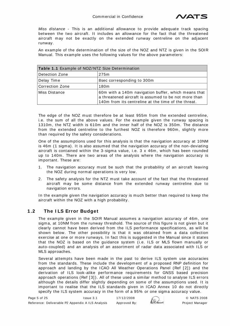
Commercial in Confidence
Page 5 of 25 Issue 3.1 17/12/2008 © NATS 2008
Reference: Deliverable P2 Appendix A ILS Analysis Approved By: Project Manager
Miss distance - This is an additional allowance to provide adequate track spacing between the two aircraft. It includes an allowance for the fact that the threatened aircraft may not be exactly on the extended runway centreline on the adjacent runway.
An example of the determination of the size of the NOZ and NTZ is given in the SOIR Manual. This example uses the following values for the above parameters:
Table 1.1 Example of NOZ/NTZ Size Determination
Detection Zone 275m
Delay Time 8sec corresponding to 300m
Correction Zone 180m
Miss Distance 60m with a 140m navigation buffer, which means that a threatened aircraft is assumed to be not more than 140m from its centreline at the time of the threat.
The edge of the NOZ must therefore be at least 955m from the extended centreline, i.e. the sum of all the above values. For the example given the runway spacing is 1310m, the NTZ width is 610m and the inner half of the NOZ is 350m. The distance from the extended centreline to the furthest NOZ is therefore 960m, slightly more than required by the safety considerations.
One of the assumptions used for this analysis is that the navigation accuracy at 10NM is 46m (1 sigma). It is also assumed that the navigation accuracy of the non-deviating aircraft is contained within the 3-sigma value, i.e. 3 x 46m, which has been rounded up to 140m. There are two areas of the analysis where the navigation accuracy is important. These are:
1. The navigation accuracy must be such that the probability of an aircraft leaving the NOZ during normal operations is very low.
2. The safety analysis for the NTZ must take account of the fact that the threatened aircraft may be some distance from the extended runway centreline due to navigation errors.
In the example given the navigation accuracy is much better than required to keep the aircraft within the NOZ with a high probability.
1.2 The ILS Error Budget
The example given in the SOIR Manual assumes a navigation accuracy of 46m, one sigma, at 10NM from the runway threshold. The source of this figure is not given but it clearly cannot have been derived from the ILS performance specifications, as will be shown below. The other possibility is that it was obtained from a data collection exercise at one or more runways. In fact this is suggested in the Manual since it states that the NOZ is based on the guidance system (i.e. ILS or MLS flown manually or auto-coupled) and an analysis of an assortment of radar data associated with ILS or MLS approaches.
Several attempts have been made in the past to derive ILS system use accuracies from the standards. These include the development of a proposed RNP definition for approach and landing by the ICAO All Weather Operations Panel (Ref [2]) and the derivation of ILS look-alike performance requirements for GNSS based precision approach operations (Ref [3]). All of these used a similar method to analyse ILS errors although the details differ slightly depending on some of the assumptions used. It is important to realise that the ILS standards given in ICAO Annex 10 do not directly specify the ILS system accuracy in the form of a 95% or one sigma accuracy value.
Commercial in Confidence
Page 6 of 25 Issue 3.1 17/12/2008 © NATS 2008
Reference: Deliverable P2 Appendix A ILS Analysis Approved By: Project Manager
The lateral error of an aircraft on an ILS approach is made up of two components. These are the Navigation System Error (NSE), which is the error at the output of the ILS receiver, and the Flight Technical Error (FTE), which is due to the inability of the pilot or autopilot to exactly follow the ILS guidance. The NSE and FTE can be combined to give the Total System Error (TSE), generally using the Root Sum Squared (RSS) method:
The NSE is made up of three main components:
Course Alignment Error - error between the runway centreline and the localiser course. This is a constant angular error throughout the approach.
Multipath (Bends) - these are the course structure errors due to multipath.
Receiver Errors - these are mainly the course centring error in the aircraft ILS receiver.
The course alignment error is not specified in the ILS standards. However there are two related standards which enable an estimate to be made. These are the adjust and maintain limit and the course alignment monitor limit e.g. for a Category III localiser the alignment adjust and maintain limit is 3m, and the monitor limit is 6m (both measured at the runway threshold). It is generally accepted that the adjust and maintain limit represents a 3-sigma value of the course alignment distribution, and that the monitor limit represents a 5-sigma value. These are not standards but they are reasonable values considering the probability of maintenance action being required and the continuity of service requirements. We can therefore estimate the course alignment error to be 2m (95%) based on the adjust and maintain limit, or 2.4m (95%) based on the monitor limit. These are both maximum values measured at the runway threshold – in practice modern ILS equipment is likely to be better than these values. Since ILS is an angular system the linear alignment error at any point on the approach is a function of the distance from threshold and the runway length.
The bends are directly specified in Annex 10 as 95% DDM values based on a sliding window technique. These values can be used directly as an estimate of course structure errors with a 95% probability, but again they represent maximum errors and most installed systems are likely to be significantly better.
Receiver centring errors are specified in Eurocae and RTCA Minimum Operational Performance Specifications (MOPS). These specifications are already in the form of 95% probabilities and specified in DDM.
We can therefore estimate the 95% NSE by taking the RSS of these three error components. This gives a linear (cross-track) NSE of 127.5m at 10NM from the runway threshold (assuming a runway length of 3500m with a localiser backset of 300m).
To estimate the FTE component we need to know how accurately the aircraft is tracking the ILS guidance. This will vary depending on the system used (autopilot, flight director, or manual). The FTE will be lowest for an aircraft flying auto-coupled to the ILS and highest for a manually flown approach. As an example we can assume that an autopilot is being used and assume a 95% FTE of 20 µA. This gives a linear error of 83.7m at 10NM from the threshold.
Finally we can estimate the TSE as the RSS of the NSE and FTE, which gives a value of 152.6m (95 %). We can compare this with the value from the SOIR Manual which is 92m (95%). Clearly this is much lower than the value estimated from the standards, even with a relatively low FTE due to the use of an autopilot. For manual flight the discrepancy will be even larger since the FTE will be considerably higher. In this case the FTE becomes 209m (assuming a 95% FTE value of 50 µA) and the TSE is then 245m.

Commercial in Confidence
Page 7 of 25 Issue 3.1 17/12/2008 © NATS 2008
Reference: Deliverable P2 Appendix A ILS Analysis Approved By: Project Manager
The most likely explanation is that the value given in the manual was taken from a data collection exercise on a good quality ILS, with most aircraft flying coupled approaches. This is a possible approach to deriving ILS accuracy figures: however the error budget method has a number of advantages providing that the results are acceptable. The principle advantage is that if measured performance is used there is an on-going need to ensure that this performance is maintained. If the error budget method is used the bend specification is the flight inspection tolerance so there is no need to take any special measures other than the normal safeguarding and flight inspection procedures.
1.2.1 Example Using the ILS Error Budget
Consider the example given in SOIR Manual but using the ILS error budget given above. We now have:
Table 1.2 Example of NOZ/NTZ Size Determination Using ILS Error Budget
Detection Zone 275m
Delay Time 8sec corresponding to 300m
Correction Zone 180m
Miss Distance 60m
Navigation accuracy (Autopilot) 76m (one sigma)
Navigation buffer (Autopilot) 228m
Navigation accuracy (Manual) 123m (one sigma)
Navigation buffer (Manual) 368m
For the autopilot case the boundary of the NOZ must now be at least 1043m from the extended centreline. It seems reasonable to keep the NOZ half width at 350m since a navigation accuracy of 76m is still sufficient to keep the aircraft within the NOZ with a high probability. The runway spacing will therefore need to be increased to about 1400m, compared with the 1310m given in the SOIR Manual.
For the manual flight example the navigation accuracy becomes 123m and the navigation buffer becomes 368m. The boundary of the NOZ must now be at least 1183m from the extended centreline. The dimension of the NOZ will have to be increased also to ensure that the probability of leaving the NOZ is sufficiently low. For example a 4-sigma value (490m) gives a probability of being within the NOZ of 0.99994, assuming a normal distribution. The runway spacing will therefore have to be increased to 1673m.
These results are summarised below:

Commercial in Confidence
Page 8 of 25 Issue 3.1 17/12/2008 © NATS 2008
Reference: Deliverable P2 Appendix A ILS Analysis Approved By: Project Manager
Table 1.3 ILS Error Budget Example Results
ILS Error Budget
SOIR Manual Example Autopilot Manual
Navigation Accuracy 46m 76m 123m
Navigation Buffer 140m 228m 368m
NOZ 350m 350m 490m
NTZ 610m 693m 693m
Runway Spacing 1310m 1393m 1673m
We can see from these examples that the use of the ILS error budget itself does not cause significant differences to the SOIR Manual example. The most significant issue is the FTE assumed.
1.3 Extended Range for Mode 1 Independent Parallel Approaches
The examples given in the SOIR Manual assume that independent parallel operations commence at 10NM for the runway threshold. Beyond this distance a vertical separation of 1000ft between the two arrival streams is maintained. The 10NM distance is probably linked to the normal distance at which glidepath coverage is available. Beyond 10NM the aircraft will be established on the localiser and when the aircraft is within 10NM it will capture the glidepath and begin the descent. In some cases it may be beneficial to start independent operations beyond 10NM and in this case there are two navigation issues to consider. Firstly, since ILS is an angular system the linear cross-track errors will increase at greater ranges. Secondly, extended glidepath coverage will be needed so that the aircraft can capture the glidepath outside 10NM.
In the case of Hong Kong, due to the terrain to the northeast of the airfield, aircraft are required to maintain 4500ft until established on the ILS. When conducting independent parallel approaches, aircraft for one runway will need to maintain 4500ft (the "low side") and 5500ft for the adjacent runway (the "high side") until both aircraft are established on the localiser, after which they can descend on the glidepath. 5500ft on the glide path equates to 17.27NM from touchdown, therefore that ILS calculations are based on maintaining 1000ft separation until 18NM from touchdown.
1.4 Preliminary Analysis of Hong Kong Options
A preliminary analysis of the Hong Kong parallel runway options has been carried out using the methodology described above. The proposed runway lengths and ILS localiser backset distances have been used. The preliminary analysis is based on a number of assumptions which will be reviewed in the next phase. These are:
1. ILS Navigation System Errors are calculated using an ILS error budget based on the Annex 10 standards. Note that the bend specification could be improved slightly by using measured performance rather than the Annex 10 limits.
2. ILS Flight Technical Error assumes manual flight with a tracking accuracy of 50 µA (95%).
3. The safety analysis for the NTZ uses the figures from the SOIR Manual example. These need to be reviewed for the proposed scenarios for Hong Kong.
4. The analysis of ILS errors assumes an aircraft distance from threshold of 18NM.

Commercial in Confidence
Page 9 of 25 Issue 3.1 17/12/2008 © NATS 2008
Reference: Deliverable P2 Appendix A ILS Analysis Approved By: Project Manager
The methodology used for the analysis is as follows:
1. Determine the one sigma navigation accuracy for the threatened aircraft at the desired range.
2. Determine the maximum cross-track error of the threatened aircraft assuming that the navigation error will be not more than three standard deviations of the navigation accuracy.
3. Calculate the minimum distance from the extended centreline of the threatened aircraft to the NOZ boundary of the parallel runway, using the safety analysis figures from the SOIR Manual example.
4. Calculate the width of the NOZ for the parallel runway by subtracting the result of step 3 from the proposed runway spacing.
5. Determine the one sigma navigation accuracy for the deviating aircraft at the desired range.
6. Calculate the probability of the deviating aircraft remaining within the NOZ assuming that is established on the localiser.
7. Confirm that this provides a sufficiently low probability of the aircraft leaving the NOZ in normal operations.
Each option is analysed below for both runway directions, when appropriate. Note that both the offset for the new runway and the stagger is given from the existing northern runway.
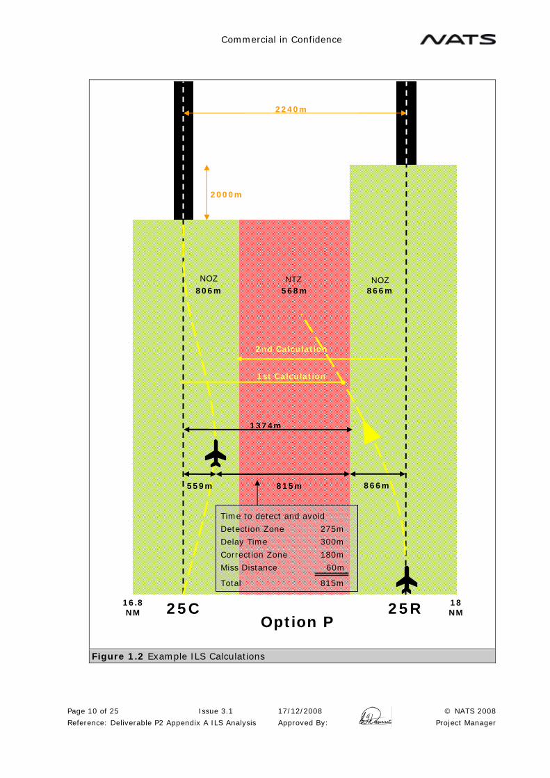
Commercial in Confidence
Page 10 of 25 Issue 3.1 17/12/2008 © NATS 2008
Reference: Deliverable P2 Appendix A ILS Analysis Approved By: Project Manager
Figure 1.2 Example ILS Calculations
25R 25C Option P
2240m
2000m
559m 815m
Time to detect and avoid
Detection Zone 275m
Delay Time 300m
Correction Zone 180m
Miss Distance 60m
Total 815m
866m
NOZ NOZ NTZ 866m 806m 568m
18 NM
16.8 NM
1st Calculation
2nd Calculation
1374m
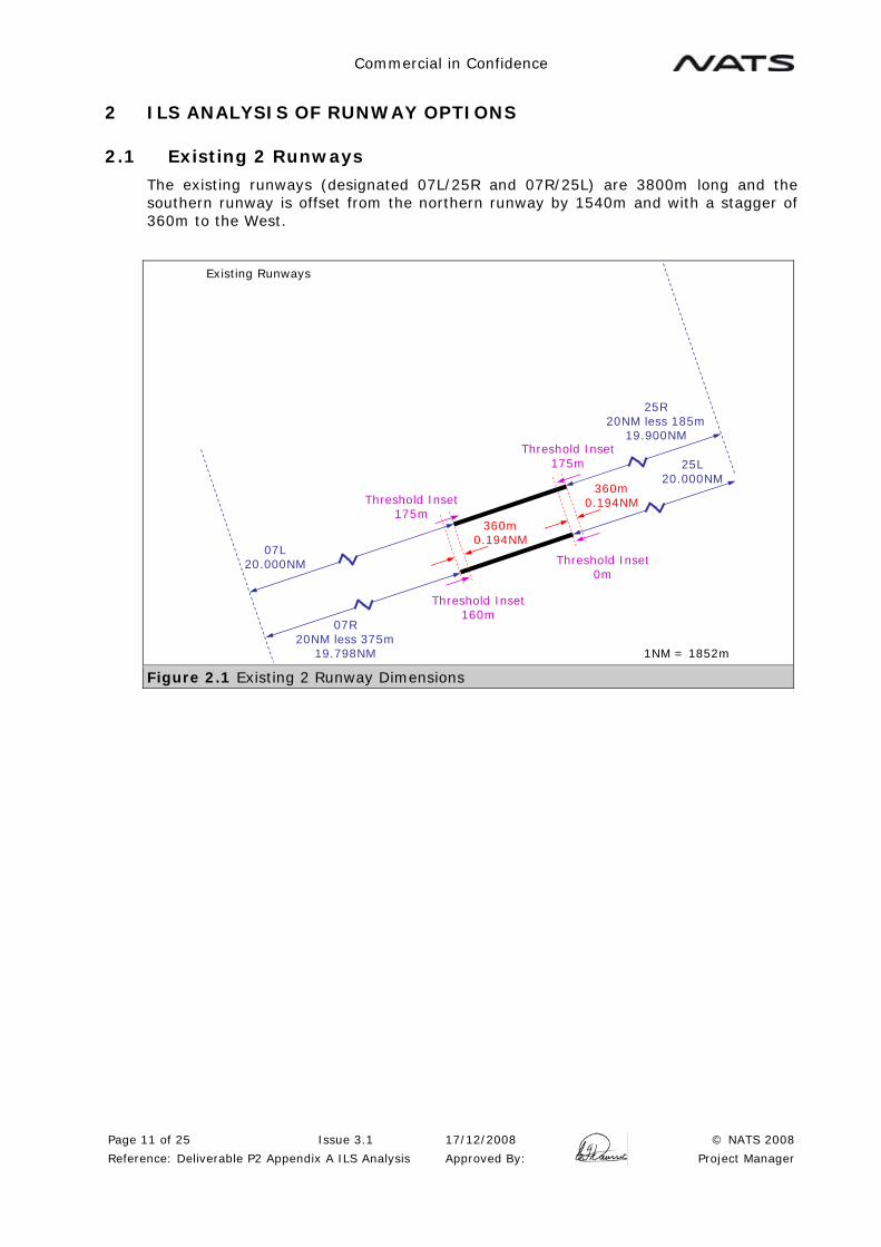
Commercial in Confidence
Page 11 of 25 Issue 3.1 17/12/2008 © NATS 2008
Reference: Deliverable P2 Appendix A ILS Analysis Approved By: Project Manager
2 ILS ANALYSIS OF RUNWAY OPTIONS
2.1 Existing 2 Runways
The existing runways (designated 07L/25R and 07R/25L) are 3800m long and the southern runway is offset from the northern runway by 1540m and with a stagger of 360m to the West.
360m0.194NM
Existing Runways
360m0.194NM
07R20NM less 375m
19.798NM
07L20.000NM
1NM = 1852m
25R20NM less 185m
19.900NM
Threshold Inset175m
Threshold Inset160m
Threshold Inset175m
Threshold Inset0m
25L20.000NM
Figure 2.1 Existing 2 Runway Dimensions

Commercial in Confidence
Page 12 of 25 Issue 3.1 17/12/2008 © NATS 2008
Reference: Deliverable P2 Appendix A ILS Analysis Approved By: Project Manager
2.1.1 Runway 07 Direction
The analysis is for an aircraft positioned at 18NM from the 07L Threshold. The aircraft on the 07L approach will be 0.2NM closer to the threshold, i.e. 17.8NM.
The analysis gives the following results:
Table 2.1 ILS Analysis Results for Existing Runway 07
Runway 07L Runway 07R
Distance from Threshold (NM) 18 17.8
Navigation Accuracy (m) (1 sigma) 198 196
Navigation Accuracy (m) (3 sigma) 594 587
Minimum distance to NOZ boundary (m) 1409 1402
NTZ Width (m) 1271 1271
NOZ Width (m) 138 131
Probability of remaining within the NOZ 0.5146 0.4972
2.1.2 Runway 25 Direction
The analysis is for an aircraft positioned at 18NM from the 25L Threshold. The aircraft on the 25R approach will be 0.1NM closer to the threshold, i.e. 17.9NM.
The analysis gives the following results:
Table 2.2 ILS Analysis Results for Existing Runway 25
Runway 25L Runway 25R
Distance from Threshold (NM) 18 17.9
Navigation Accuracy (m) (1 sigma) 197 190
Navigation Accuracy (m) (3 sigma) 591 571
Minimum distance to NOZ boundary (m) 1406 1386
NTZ Width (m) 1253 1253
NOZ Width (m) 134 154
Probability of remaining within the NOZ 0.5175 0.5640
Comment: In both directions, this runway combination is not acceptable for independent approaches since the probability of remaining within the NOZ in normal operations is too low.

Commercial in Confidence
Page 13 of 25 Issue 3.1 17/12/2008 © NATS 2008
Reference: Deliverable P2 Appendix A ILS Analysis Approved By: Project Manager
2.2 Option P Wide Spaced Parallel Runway (2240m) Offset to the West
For this option the new runway (designated 07L and 25R) is 3446m long, offset from the existing northern runway by 2240m and with a stagger of 2000m to the West. The spacing between the new runway and the existing 07R/25L runway is 3780m.
2380m1.285NM
2020m1.091NM
360m0.194NM
2000m1.080NM
1640m0.886NM
Option P
360m0.194NM
07R20.000NM
07L20NM less 1800m
19.028NM
25C20Nm less 2205m
18.809NM
25R20.000NM
1Nm = 1852m
Threshold Inset175m
Threshold Inset160m
Threshold Inset175m
Threshold Inset0m
Threshold Inset0m
Threshold Inset0m
Figure 2.2 Option P Dimensions

Commercial in Confidence
Page 14 of 25 Issue 3.1 17/12/2008 © NATS 2008
Reference: Deliverable P2 Appendix A ILS Analysis Approved By: Project Manager
2.2.1 Runway 07 Direction
The analysis is for an aircraft position at 18NM from the 07R Threshold. The aircraft on the 07L approach will be 0.97NM closer to the threshold, i.e. 17.03NM.
The analysis gives the following results:
Table 2.3 ILS Analysis Results for Option P Runway 07
Runway 07L Runway 07R
Distance from Threshold (NM) 17.03 18
Navigation Accuracy (m) (1 sigma) 196 198
Navigation Accuracy (m) (3 sigma) 589 593
Minimum distance to NOZ boundary (m) 1404 1408
NTZ Width (m) 1032 1032
NOZ Width (m) 1372 1376
Probability of remaining within the NOZ 1 1
Comment: The runway spacing for this option is so large that the NOZ and NTZ widths given are arbitrary and other combinations would be acceptable provided that the minimum distance to the NOZ boundary is met.
2.2.2 Runway 25 Direction
The analysis is for an aircraft position at 18NM from the 25R Threshold. The aircraft on the 25C approach will be 1.2NM closer to the threshold, i.e. 16.8NM.
The analysis gives the following results:
Table 2.4 ILS Analysis Results for Option P Runway 25
Runway 25C Runway 25R
Distance from Threshold (NM) 16.8 18
Navigation Accuracy (m) (1 sigma) 186 206
Navigation Accuracy (m) (3 sigma) 559 619
Minimum distance to NOZ boundary (m) 1374 1434
NTZ Width (m) 568 568
NOZ Width (m) 806 866
Probability of remaining within the NOZ 1 1
Comment: In the Runway 25 direction, the probability of an aircraft established on the localiser departing the NOZ is less than 0.1 %, assuming that the navigation errors have a normal distribution. In practice the probabilities will be significantly lower than this since the bends will be better than the Annex 10 limit, and the majority of aircraft will track the ILS guidance more accurately than assumed in the analysis.

Commercial in Confidence
Page 15 of 25 Issue 3.1 17/12/2008 © NATS 2008
Reference: Deliverable P2 Appendix A ILS Analysis Approved By: Project Manager
2.3 Option R Parallel Runway at 1525m Offset to the West
For this option the new runway (designated 07L and 25R) is 3800m long, offset from the existing northern runway by 1525m and with a stagger of 1430m to the West. The spacing between the new runway and the existing 07R/25L runway is 3065m. The 07 direction is based on Runways 07L and 07R. The 25 direction is based on 25R and 25C.
1430m0.772NM
1070m0.578NM
Option R
1430m0.772NM
1070m0.578NM
360m0.194Nm
360m0.194Nm
07R20.000NM
07L20NM less 1230m
19.336NM
25C20NM less 1255m
19.322NM
25R20.000NM
1Nm = 1852m
Threshold Inset175m
Threshold Inset160m
Threshold Inset175m
Threshold Inset0m
Threshold Inset0m
Threshold Inset0m
Figure 2.3 Option R Dimensions

Commercial in Confidence
Page 16 of 25 Issue 3.1 17/12/2008 © NATS 2008
Reference: Deliverable P2 Appendix A ILS Analysis Approved By: Project Manager
2.3.1 Runway 07 Direction
The analysis is for an aircraft position at 18NM from the 07R Threshold. The aircraft on the 07L approach will be 0.7NM closer to the threshold, i.e. 17.3NM.
The analysis gives the following results:
Table 2.5 ILS Analysis Results for Option R Runway 07
Runway 07L Runway 07R
Distance from Threshold (NM) 17.3 18
Navigation Accuracy (m) (1 sigma) 184 198
Navigation Accuracy (m) (3 sigma) 552 593
Minimum distance to NOZ boundary (m) 1367 1408
NTZ Width (m) 910 910
NOZ Width (m) 1057 1098
Probability of remaining within the NOZ 1 1
Comment: The runway spacing for this option is so large that the NOZ and NTZ widths given are fairly arbitrary and other combinations would be acceptable provided that the minimum distance to the NOZ boundary is met.
2.3.2 Runway 25 Direction
The analysis is for an aircraft position at 18NM from the 25R Threshold. The aircraft on the 25C approach will be 0.7NM closer to the threshold, i.e. 17.3NM. The runway spacing is 1525m.
The analysis gives the following results:
Table 2.6 ILS Analysis Results for Option R Runway 25
Runway 25C Runway 25R
Distance from Threshold (NM) 17.3 18
Navigation Accuracy (m) (1 sigma) 191 190
Navigation Accuracy (m) (3 sigma) 574 571
Minimum distance to NOZ boundary (m) 1389 1386
NTZ Width (m) 1250 1250
NOZ Width (m) 139 136
Probability of remaining within the NOZ 0.5327 0.5246
Comment: This option is not acceptable for independent approaches since the probability of remaining within the NOZ in normal operations is too low.

Commercial in Confidence
Page 17 of 25 Issue 3.1 17/12/2008 © NATS 2008
Reference: Deliverable P2 Appendix A ILS Analysis Approved By: Project Manager
2.4 Option S Extended (Variants A, B and C) Close Spaced Parallel Runway Extended to the West
For this option the new runway (designated 07L and 25R) is 5689m long, offset from the existing northern runway by 380m and with a stagger of 1889m to the West. The spacing between the new runway and the existing 07R/25L runway is 1920m.
1889m1.020NM
1529m0.826NM
Option SX-ABC
360m0.194NM
360m0.194NM
07R20.000NM
07L20NM less 1689m
19.088NM
25R20NM less 360m
19.806NM
25L20.000NM
1Nm = 1852m
Threshold Inset0m
Threshold Inset0m
Threshold Inset175m
Threshold Inset160m
Threshold Inset175m
Threshold Inset0m
Figure 2.4 Option S Extended (Variants A, B and C) Dimensions
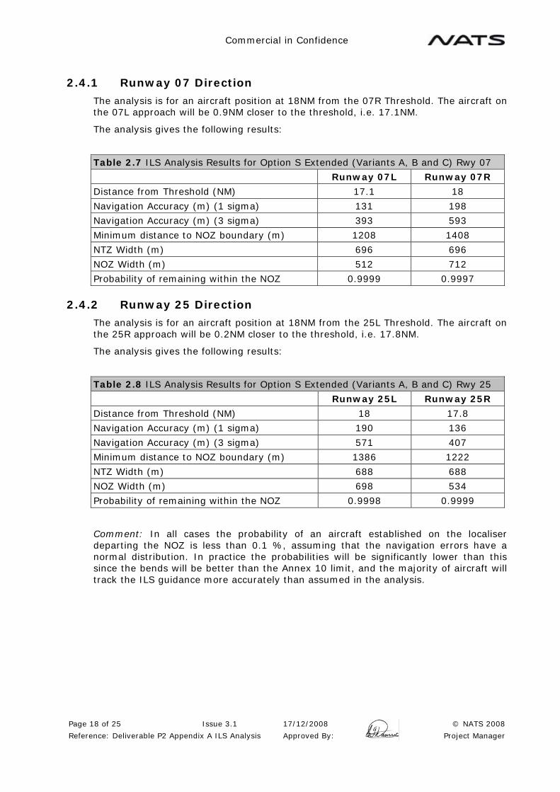
Commercial in Confidence
Page 18 of 25 Issue 3.1 17/12/2008 © NATS 2008
Reference: Deliverable P2 Appendix A ILS Analysis Approved By: Project Manager
2.4.1 Runway 07 Direction
The analysis is for an aircraft position at 18NM from the 07R Threshold. The aircraft on the 07L approach will be 0.9NM closer to the threshold, i.e. 17.1NM.
The analysis gives the following results:
Table 2.7 ILS Analysis Results for Option S Extended (Variants A, B and C) Rwy 07
Runway 07L Runway 07R
Distance from Threshold (NM) 17.1 18
Navigation Accuracy (m) (1 sigma) 131 198
Navigation Accuracy (m) (3 sigma) 393 593
Minimum distance to NOZ boundary (m) 1208 1408
NTZ Width (m) 696 696
NOZ Width (m) 512 712
Probability of remaining within the NOZ 0.9999 0.9997
2.4.2 Runway 25 Direction
The analysis is for an aircraft position at 18NM from the 25L Threshold. The aircraft on the 25R approach will be 0.2NM closer to the threshold, i.e. 17.8NM.
The analysis gives the following results:
Table 2.8 ILS Analysis Results for Option S Extended (Variants A, B and C) Rwy 25
Runway 25L Runway 25R
Distance from Threshold (NM) 18 17.8
Navigation Accuracy (m) (1 sigma) 190 136
Navigation Accuracy (m) (3 sigma) 571 407
Minimum distance to NOZ boundary (m) 1386 1222
NTZ Width (m) 688 688
NOZ Width (m) 698 534
Probability of remaining within the NOZ 0.9998 0.9999
Comment: In all cases the probability of an aircraft established on the localiser departing the NOZ is less than 0.1 %, assuming that the navigation errors have a normal distribution. In practice the probabilities will be significantly lower than this since the bends will be better than the Annex 10 limit, and the majority of aircraft will track the ILS guidance more accurately than assumed in the analysis.

Commercial in Confidence
Page 19 of 25 Issue 3.1 17/12/2008 © NATS 2008
Reference: Deliverable P2 Appendix A ILS Analysis Approved By: Project Manager
2.5 Option S Extended (Variants D and E) Close Spaced Parallel Runway Extended to the East and West
For this option the new runway (designated 07L and 25R) is 6689m long, offset from the existing northern runway by 380m, with a stagger of 1889m to the West and 1000m to the East. The spacing between the new runway and the existing 07R/25L runway is 1920m
1360m0.734NM
1000m0.540NM
Option SX-DE
25R20NM less 1360m
19.266NM
25L20.000Nm
360m0.194NM
360m0.194NM
1Nm = 1852m
07R20.000NM
07L20NM less 1689m
19.088NM
Threshold Inset0m Threshold Inset
175m
Threshold Inset160m
1889m1.020NM
1529m0.826NM
Threshold Inset0m
Threshold Inset175m
Threshold Inset0m
Figure 2.5 Option S Extended (Variants D and E) Dimensions
2.5.1 Runway 07 Direction
The analysis is for an aircraft position at 18NM from the 07R Threshold. The aircraft on the 07L approach will be 0.9NM closer to the threshold, i.e. 17.1NM.
The analysis gives the following results:
Table 2.9 ILS Analysis Results for Option S Extended (Variants D and E) Runway 07
Runway 07L Runway 07R
Distance from Threshold (NM) 17.1 18
Navigation Accuracy (m) (1 sigma) 115 198
Navigation Accuracy (m) (3 sigma) 346 593
Minimum distance to NOZ boundary (m) 1161 1408
NTZ Width (m) 649 649
NOZ Width (m) 512 759
Probability of remaining within the NOZ 1 0.9999

Commercial in Confidence
Page 20 of 25 Issue 3.1 17/12/2008 © NATS 2008
Reference: Deliverable P2 Appendix A ILS Analysis Approved By: Project Manager
2.5.2 Runway 25 Direction
The analysis is for an aircraft position at 18NM from the 25L Threshold. The aircraft on the 25R approach will be 0.7NM closer to the threshold, i.e. 17.3NM.
The analysis gives the following results:
Table 2.10 ILS Analysis Results for Option S Extended (Variants D and E) Rwy 25
Runway 25L Runway 25R
Distance from Threshold (NM) 18 17.3
Navigation Accuracy (m) (1 sigma) 190 116
Navigation Accuracy (m) (3 sigma) 571 349
Minimum distance to NOZ boundary (m) 1386 1164
NTZ Width (m) 630 630
NOZ Width (m) 756 534
Probability of remaining within the NOZ 0.9999 1
Comment: In all cases the probability of an aircraft established on the localiser departing the NOZ is less than 0.1%, assuming that the navigation errors have a normal distribution. In practice the probabilities will be significantly lower than this since the bends will be better than the Annex 10 limit, and the majority of aircraft will track the ILS guidance more accurately than assumed in the analysis.
The results for this option are shown in the figure below.
Figure 2.6 Option S Extended (Variants D and E)
25L
25R
07R
07L
NOZ (759m)
NOZ (512m)
NOZ (756m)
NOZ (534m)
NTZ (630m) NTZ (649m)

Commercial in Confidence
Page 21 of 25 Issue 3.1 17/12/2008 © NATS 2008
Reference: Deliverable P2 Appendix A ILS Analysis Approved By: Project Manager
2.6 Summary of ILS Analysis (SOIR Compliant breakout)
A summary of the results for all runway option is shown in the table below.
Table 2.11 Summary of ILS Analysis Results for all Runway Options
NTZ Width
(m) NOZ Width
(m)
Probability of remaining within the
NOZ
Existing Runways 07L/07R 1271 138/131 0.5146/0.4972
Existing Runways 25L/25R 1253 134/154 0.5175/0.5640
Option P Runways 07L/07R 1032 1372/1376 1/1
Option P Runways 25C/25R 568 806/866 1/1
Option R Runways 07L/07R 910 1057/1098 1/1
Option R Runways 25C/25R 1250 139/136 0.5327/0.5246
Option S Ext A/B/C Runways 07L/07R
696 512/712 0.9999/0.9997
Option S Ext A/B/C Runways 25L/25R
688 698/534 0.9998/0.9999
Option S Ext D/E Runways 07L/07R
649 512/759 1/0.9999
Option S Ext D/E Runways 25L/25R
630 756/534 0.9999/1
The analysis of the existing runways shows that they are not suitable for independent parallel approaches, based on the criteria in paragraph 1.4 above. Although the runway offset of 1540m is greater that the minimum SOIR manual requirement (1035m), the longer final (18NM rather than 10NM) and the lower navigation accuracy assumed (the use of the Annex 10 accuracy, rather than measured accuracy) mean that the runway offset is not sufficient to support these operations.
Only one case was identified for the new runway options where the approaches could not be supported and this was Option R in the Runway 25 direction. The proposed mode of operations uses Runway 25C and Runway 25R for arrivals. This is the most closely spaced runway pair evaluated. The problem can be mitigated most easily by changing the mode of operation with Runway 25L and Runway 25R for landing. This will then become the widest runway spacing in the analysis.
2.7 ILS Analysis (Proposed Breakout Manoeuvre)
An analysis of independent parallel approaches was conducted using the proposed breakout manoeuvre to turn the blundering aircraft.
The same analysis (see Section 1.4) was undertaken, but with the addition of a second Delay Time of 8 seconds (300m) and the Correction Zone increased to 10 seconds (411m).

Commercial in Confidence
Page 22 of 25 Issue 3.1 17/12/2008 © NATS 2008
Reference: Deliverable P2 Appendix A ILS Analysis Approved By: Project Manager
2.8 Option P Wide Spaced Parallel Runway (2240m) Offset to the West
The analysis gives the following results:
Table 2.12 ILS Analysis Results for Option P Runway 07 (Proposed Breakout)
Runway 07L Runway 07R
Distance from Threshold (NM) 17.02 18
Navigation Accuracy (m) (1 sigma) 196.2 197.6
Navigation Accuracy (m) (3 sigma) 588.8 592.8
Minimum distance to NOZ boundary (m) 1934.8 1938.8
NTZ Width (m) 1694 1694
NOZ Width (m) 1041 1045
Probability of remaining within the NOZ 1 1
In the Runway 25 Direction, Runways 25L and 25R have been selected for landing.
Table 2.13 ILS Analysis Results for Option P Runway 25 (Proposed Breakout)
Runway 25L Runway 25R
Distance from Threshold (NM) 16.8 18
Navigation Accuracy (m) (1 sigma) 180.3 206.2
Navigation Accuracy (m) (3 sigma) 541.0 618.8
Minimum distance to NOZ boundary (m) 1887.0 1964.8
NTZ Width (m) 1672 1672
NOZ Width (m) 1015 1093
Probability of remaining within the NOZ 1 1
Comment: The runway spacing for this option is so large that the NOZ and NTZ widths given are arbitrary and other combinations would be acceptable provided that the minimum distance to the NOZ boundary is met.

Commercial in Confidence
Page 23 of 25 Issue 3.1 17/12/2008 © NATS 2008
Reference: Deliverable P2 Appendix A ILS Analysis Approved By: Project Manager
2.9 Option R Parallel Runway at 1525m Offset to the West
The analysis gives the following results:
Table 2.14 ILS Analysis Results for Option R Runway 07 (Proposed Breakout)
Runway 07L Runway 07R
Distance from Threshold (NM) 17.3 18
Navigation Accuracy (m) (1 sigma) 184.0 197.6
Navigation Accuracy (m) (3 sigma) 552.1 592.8
Minimum distance to NOZ boundary (m) 1898.1 1938.8
NTZ Width (m) 972 972
NOZ Width (m) 1026 1067
Probability of remaining within the NOZ 1 1
In the Runway 25 Direction, Runways 25L and 25R have been selected for landing.
Table 2.15 ILS Analysis Results for Option R Runway 25 (Proposed Breakout)
Runway 25L Runway 25R
Distance from Threshold (NM) 17.3 18
Navigation Accuracy (m) (1 sigma) 185.0 190.2
Navigation Accuracy (m) (3 sigma) 555.1 570.8
Minimum distance to NOZ boundary (m) 1901.1 1916.8
NTZ Width (m) 953 953
NOZ Width (m) 1048 1064
Probability of remaining within the NOZ 1 1
Comment: The runway spacing for this option is so large that the NOZ and NTZ widths given are arbitrary and other combinations would be acceptable provided that the minimum distance to the NOZ boundary is met.

Commercial in Confidence
Page 24 of 25 Issue 3.1 17/12/2008 © NATS 2008
Reference: Deliverable P2 Appendix A ILS Analysis Approved By: Project Manager
2.10 Option S Extended (All Variants)
The substantial increase in the delay time and correction zone above those given in the SOIR manual example mean that this breakout manoeuvre cannot be supported with runway spacing below around 2500m. The figures for S Extended Variants D and E are given below to demonstrate this. Similarly these approaches could not be supported in S Extended (Variants A, B and C).
The analysis gives the following results:
Table 2.16 ILS Analysis Results for Option S Extended (Variants D and E) Runway 07 (Proposed Breakout)
Runway 07L Runway 07R
Distance from Threshold (NM) 17.1 18
Navigation Accuracy (m) (1 sigma) 115.2 197.6
Navigation Accuracy (m) (3 sigma) 345.8 592.8
Minimum distance to NOZ boundary (m) 1691.8 1938.8
NTZ Width (m) 1711 1711
NOZ Width (m) -19 228
Probability of remaining within the NOZ -0.1298 0.7518
Table 2.17 ILS Analysis Results for Option S Extended (Variants D and E) Runway 25 (Proposed Breakout)
Runway 25L Runway 25R
Distance from Threshold (NM) 18 17.26
Navigation Accuracy (m) (1 sigma) 190.4 116.2
Navigation Accuracy (m) (3 sigma) 571.4 348.7
Minimum distance to NOZ boundary (m) 1917.4 1694.7
NTZ Width (m) 1692 1692
NOZ Width (m) 225 3
Probability of remaining within the NOZ 0.7630 0.172
Comment: This option is not acceptable for independent approaches since the probability of remaining within the NOZ in normal operations is too low (in the case of the Runway 07L, the NOZ value is negative, indicating that there is not sufficient room to establish a NOZ).

Commercial in Confidence
Page 25 of 25 Issue 3.1 17/12/2008 © NATS 2008
Reference: Deliverable P2 Appendix A ILS Analysis Approved By: Project Manager
2.11 Summary of ILS Analysis (Proposed Breakout Manoeuvre)
A summary of the results for all runway options is shown in the table below.
Table 2.18 Summary of ILS Analysis Results for All Runway Options (Proposed Breakout)
NTZ Width
(m) NOZ Width
(m)
Probability of remaining
within the NOZ
Option P Runway 07L/07R 1694 1041/1045 1/1
Option P Runway 25L/25R 1672 1015/1093 1/1
Option R Runway 07L/07R 972 1026/1067 1/1
Option R Runway 25L/25R 953 1048/1064 1/1
Option S Ext D/E Runway 07L/07R
1711 -19/228 -0.1298/0.7518
Option S Ext D/E Runway 25L/25R
1692 225/3 0.7630/0.172
The increased runway separation (around 2500m) required to support the proposed breakout manoeuvre means that independent parallel approaches cannot be supported in Option S Extended (All Variants).

Commercial in Confidence
Page 1 of 40 Issue 3.1 17/12/2008 © NATS 2008
Reference: Deliverable P2 App B Modes of Operation Approved By: Project Manager
AIRSPACE AND RUNWAY CAPACITY STUDY PHASE 1b
Appendix B
Modes of Operation – Three Runways

Commercial in Confidence
Page 2 of 40 Issue 3.1 17/12/2008 © NATS 2008
Reference: Deliverable P2 App B Modes of Operation Approved By: Project Manager
CONTENTS
1 INTRODUCTION ...............................................................................................3 2 INITIAL INVESTIGATION OF MODES OF OPERATION..............................................3 3 DETAILED REVIEW OF MODES OF OPERATION FOR EACH RUNWAY OPTION..............9
3.1 Options P and R............................................................................................ 9 3.2 Option S Extended (All Variants)................................................................... 24

Commercial in Confidence
Page 3 of 40 Issue 3.1 17/12/2008 © NATS 2008
Reference: Deliverable P2 App B Modes of Operation Approved By: Project Manager
1 INTRODUCTION
When considering a 3-runway airport it is essential to describe the intended mode of operation for each runway. This then allows any operational issues to be identified, suitable mitigations and procedures to be developed, and the capacity of the 3-runway configuration to be derived.
This Appendix describes the process of evaluating the potential modes of operation for SOIR compliance, operability and capacity. An initial, high level, review identified a number of core operating modes.
The three runway options (including variants) have been assessed based on the modes of operation selected from the initial review. The issues have been identified and a number of mitigation measures have been proposed. The capacity of each mode of operation, before and after the implementation of these mitigations has then been assessed.
The review has been undertaken by developing a table for each runway option, for each mode of operation and in both the Runway 25 and the Runway 07 directions. The SOIR compliance issues in respect of parallel approaches, departures, missed approaches and wake vortex are identified in each case. Possible mitigations are then proposed where appropriate and considered to be viable. Each table contains an assessment of the potential capacity of the airport operating in the chosen mode of operation on the assumption that the issues have been resolved. A final table for each option describes the primary mode of operation and the actual capacity that is likely to be achieved. Due to the significant and complex nature of the issues, particularly the interaction between the various issues, these capacity figures may be significantly lower than the theoretical maximum capacity.
Finally, a recommendation is made as to the most effective way of operating the primary mode for both Easterly and Westerly along with an achievable capacity figure, assuming the required mitigations and procedures are in place. Other subsidiary modes may also be identified that would be suitable to deal with arrival and departure peaks.
2 INITIAL INVESTIGATION OF MODES OF OPERATION
The modes of operation are described for each runway from North to South.
Mode of Operations may be arrivals only (A), departures only (D) or Mixed Mode arrivals and departures (MM).
For a 3-runway airport, each runway is, in theory, capable of operating in one of these three modes, resulting in 27 potential operating modes. These 27 modes have been placed in a table and each mode evaluated for operability and capacity. At the end of this process a number of core operating modes are identified as suitable for further investigation.
The outcome of the review is N – Not viable or Y – Suitable for detailed investigation.
Note 1: In S Extended, Mixed Mode is not viable on the Northern pair of runways as they are dependant.
Note 2: An arrival on the Centre Runway is not viable as the missed approach is not separated from missed approaches and departures from the other runways.

Commercial in Confidence
Page 4 of 40 Issue 3.1 17/12/2008 © NATS 2008
Reference: Deliverable P2 App B Modes of Operation Approved By: Project Manager
Note 3: There is not felt to be sufficient demand to justify establishing little used procedures to support triple arrival stream. The management of triple arrival steams is considered to be unacceptably complex and these modes have been excluded.
Table 2.1 Table of 27 Possible Modes of Operation
Mode of Operations
Option S Extended Option P & R
1. MM/MM/MM N Mixed Mode not viable on the Northern pair of
runways Note1 Complex triple arrival
stream Note3 Complex triple departure
stream
N No acceptable Missed Approach from the Centre
Runway Note2 Complex triple arrival
stream Note3 Complex triple departure
stream
2. MM/MM/A N Mixed Mode not viable on the Northern pair of
runways Note1 Arrival on the Centre
Runway not viable Note2
N Arrivals & Departures not balanced.
No acceptable Missed Approach from the Centre
Runway Note2 Complex triple arrival
stream Note3
3. MM/MM/D N Mixed Mode not viable on the Northern pair of
runways Note1 Arrival on the Centre
Runway not viable Note2 Complex triple departure
stream
N Arrivals and Departures not balanced.
No acceptable Missed Approach from the Centre
Runway Note2 Complex triple departure
stream
4. MM/A/MM N Mixed Mode not viable on the Northern pair of
runways Note1 Arrival on the Centre
Runway not viable Note2
N Complex triple arrival stream Note3
Issue with Missed Approach from the Centre Runway and dependent
arrival streams
5. MM/D/MM N Mixed Mode not viable on the Northern pair of
runways Note1 Complex triple departure
stream
N Arrivals & Departures not Balanced.
Complex triple departure stream
6. MM/D/D N Mixed Mode not viable on the Northern pair of
runways Note1 Complex triple departure
stream
N Arrivals & Departures not balanced.
Complex triple departure stream
7. MM/A/A N Mixed Mode not viable on the Northern pair of
runways Note1 Complex triple arrival
stream Note3
N Arrivals and Departures not balanced.
No acceptable Missed Approach from the Centre
Runway Note2 Complex triple arrival
stream Note3

Commercial in Confidence
Page 5 of 40 Issue 3.1 17/12/2008 © NATS 2008
Reference: Deliverable P2 App B Modes of Operation Approved By: Project Manager
8. MM/A/D N Mixed Mode not viable on the Northern pair of
runways Note1
Y Issue with Missed Approach from the
Centre Runway Worthy of further
investigation
9. MM/D/A N Mixed Mode not viable on the Northern pair of
runways Note1
Y Worthy of further investigation
10.D/MM/MM N Mixed Mode not viable on the Northern pair of
runways Note1 Complex triple departure
stream
N Arrivals & Departures not balanced
Complex triple departure stream
No acceptable Missed Approach from the Centre
Runway Note2
11. D/MM/A N Mixed Mode not viable on the Northern pair of
runways Note1
N No acceptable Missed Approach from the Centre
Runway Note2
12. D/MM/D N Mixed Mode not viable on the Northern pair of
runways Note1 Complex triple departure
stream
N Arrivals & Departures not balanced.
Complex triple departure stream
No acceptable Missed Approach from the Centre
Runway Note2
13. D/A/MM N Arrival on the Centre Runway not viable Note1
Y Issue with Missed Approach from the
Centre Runway Worthy of further
investigation
14. D/D/MM N Simultaneous departures on the northern pair of runways not viable Note1
Complex triple departure stream
N Arrivals & Departures not balanced
Complex triple departure stream
15. D/D/D N Arrivals & Departures not balanced
Simultaneous departures on the northern pair of runways not viable Note1
Complex triple departure stream
N Arrivals & Departures not balanced
Complex triple departure stream
16. D/A/A N Arrivals & Departures not balanced
Arrival on the Centre Runway not viable due stagger (dependant on
Departures). No viable Missed Approach from Centre Runway Note2
N Arrivals & Departures not balanced
Arrival on the Centre Runway not viable Note2

Commercial in Confidence
Page 6 of 40 Issue 3.1 17/12/2008 © NATS 2008
Reference: Deliverable P2 App B Modes of Operation Approved By: Project Manager
17. D/A/D N Arrival on the Centre Runway not viable due stagger (dependant on
Departures). Arrival on the Centre
Runway not viable Note2
Y Arrivals & Departures not balanced
Worthy of further investigation
18. D/D/A N Arrivals & Departures not balanced
Simultaneous departures not possible on the
Northern pair of runways Note1
Y Arrivals & Departures not balanced
Worthy of further investigation
19. A/MM/MM N Mixed Mode not viable on the Northern pair of
runways Note1
N No acceptable Missed Approach from the Centre
Runway Note2 Complex triple arrival
stream Note3
20. A/MM/A N Arrivals & Departures not balanced
Mixed Mode not viable on the Northern pair of
runways Note1
N Arrivals & Departures not balanced
No acceptable Missed Approach from the Centre
Runway Note2 Complex triple arrival
stream Note3
21. A/MM/D N Mixed Mode not viable on the Northern pair of
runways Note1
Y Issue with Missed Approach from the
Centre Runway Worthy of further
investigation
22. A/A/MM N Arrivals & Departures not balanced
Arrival on the Centre Runway not viable due
Northern runways dependant
N Arrivals & Departures not balanced
Arrival on the Centre Runway not viable Note2 Complex triple arrival
stream Note3
23. A/D/MM Y Worthy of further investigation
Y Worthy of further investigation
24. A/D/D Y Arrivals & Departures not balanced
Worthy of further investigation
Y Arrivals & Departures not balanced
Worthy of further investigation
25. A/A/A N Arrivals & Departures not balanced
Arrival on the Centre Runway not viable due
Northern runways dependant
N Arrivals & Departures not balanced
Arrival on the Centre Runway not viable Note2 Complex triple arrival
stream Note3
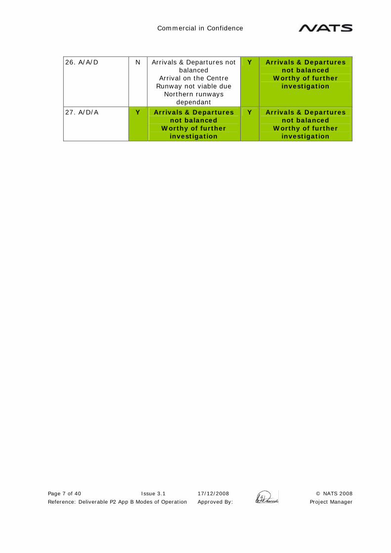
Commercial in Confidence
Page 7 of 40 Issue 3.1 17/12/2008 © NATS 2008
Reference: Deliverable P2 App B Modes of Operation Approved By: Project Manager
26. A/A/D N Arrivals & Departures not balanced
Arrival on the Centre Runway not viable due
Northern runways dependant
Y Arrivals & Departures not balanced
Worthy of further investigation
27. A/D/A Y Arrivals & Departures not balanced
Worthy of further investigation
Y Arrivals & Departures not balanced
Worthy of further investigation

Commercial in Confidence
Page 8 of 40 Issue 3.1 17/12/2008 © NATS 2008
Reference: Deliverable P2 App B Modes of Operation Approved By: Project Manager
The above analysis identifies that the following viable modes require further evaluation:
Table 2.2 Table of Viable Modes of Operation
Mode of Operations
Option S Extended Option P & R
8. MM/A/D Y Issue with Missed Approach from the
Centre Runway Worthy of further
investigation
9. MM/D/A Y Worthy of further investigation
13. D/A/MM Y Issue with Missed Approach from the
Centre Runway Worthy of further
investigation
17. D/A/D Y Arrivals & Departures not balanced
Worthy of further investigation
18. D/D/A Y Arrivals & Departures not balanced
Worthy of further investigation
21. A/MM/D Y Issue with Missed Approach from the
Centre Runway Worthy of further
investigation
23. A/D/MM Y Worthy of further investigation
Y Worthy of further investigation
24. A/D/D Y Arrivals & Departures not balanced
Worthy of further investigation
Y Arrivals & Departures not balanced
Worthy of further investigation
26. A/A/D Y Arrivals & Departures not balanced
Worthy of further investigation
27. A/D/A Y Arrivals & Departures not balanced
Worthy of further investigation
Y Arrivals & Departures not balanced
Worthy of further investigation

Commercial in Confidence
Page 9 of 40 Issue 3.1 17/12/2008 © NATS 2008
Reference: Deliverable P2 App B Modes of Operation Approved By: Project Manager
3 DETAILED REVIEW OF MODES OF OPERATION FOR EACH RUNWAY OPTION
The three runway options (including variants) have been assessed based on the modes of operation selected from the initial review. The issues have been identified and a number of mitigation measures have been proposed. The capacity of each option in the recommended mode of operation, after implementation of these mitigations, has then been assessed.
3.1 Options P and R
The possible modes of operation for Options P and R have been reviewed and the results are summarised in Table 2.2 above. A number of modes have subsequently been rejected as they are not able to support the desired operations. These are:
Table 3.1 Rejected Modes of Operation
Mode Reason
13 The Centre and South Runways (the existing runways) are not able to support Independent Parallel Approaches (See ILS Analysis in Appendix A). It is not possible to achieve 30 degrees separation between the missed approaches from these runways.
17 This is a departure peak mode that could be used to support Mode 13 as a primary mode. As Mode 13 has been rejected, this mode will not be investigated further.
18 This is a departure peak mode that could be used to support Mode 9 as a primary mode. Mode 9 has been rejected in the detailed investigation (see below), so this mode will not be investigated further.
26 This is an arrival peak mode that could be used to support Mode 8 as a primary mode. Mode 8 has been rejected in the detailed investigation (see below), so this mode will not be investigated further.
Modes 8, 9, 21, 23, 24 and 27 have been selected for detailed investigation.

Commercial in Confidence
Page 10 of 40 Issue 3.1 17/12/2008 © NATS 2008
Reference: Deliverable P2 App B Modes of Operation Approved By: Project Manager
Options P & R Runway
25 Mode 8
MM/A/D Runway
Separation 2240/1525m
Runway Use Capacity
25R Mixed 44
25C Arrivals 33
25L Departures 35
Total 112
Increase 44
Independent Parallel Approach Issues and Mitigations
A safety case needs to be developed for ILS performance and breakout manoeuvres to support independent parallel approaches.
SOIR Departure Issues and Mitigations
Two departure tracks diverge by 15 degrees and there are no departure issues.
SOIR Missed Approach Issues and Mitigations
The Runway 25C missed approach track needs to climb straight ahead for separation from the other runways. It may be possible to turn the 25L missed approach left by 15 degrees at the upwind end of the runway. The SID from Runway 25R could turn right by 30 degree in order to be SOIR compliant, but 15 degrees may be sufficient for both Runways 25R and 25L.
The Runway 25R missed approach can turn right by 30 degrees or more from the Runway 25R SID, but both turn in the same direction, which is not SOIR compliant.
A specific safety case will be required for operations with a missed approach track that does not diverge by 30 degrees from the adjacent runway track, or where both tracks turn in the same direction.
Wake Vortex Issues and Mitigations
There are no wake vortex issues.
Balance/Operability Issues
This mode is balanced for arrivals and departures and is, therefore, a Primary operating mode.
Summary
This mode is rejected due to parallel approach issues and Centre Runway missed approach. It was also noted that any crossings of the Centre Runway would be required to cross an arrival runway, which is less desirable than crossing a departure runway.

Commercial in Confidence
Page 11 of 40 Issue 3.1 17/12/2008 © NATS 2008
Reference: Deliverable P2 App B Modes of Operation Approved By: Project Manager
Options P & R Runway
25 Mode 9
MM/D/A Runway
Separation 2240/1525m
Runway Use Capacity
25R Mixed 44
25C Arrivals 33
25L Departures 35
Total 112
Increase 44
Independent Parallel Approach Issues and Mitigations
A Safety case needs to be developed for ILS performance and breakout manoeuvres to support independent parallel approaches.
SOIR Departure Issues and Mitigations
Two departure tracks diverge by 15 degrees and there are no departure issues.
SOIR Missed Approach Issues and Mitigations
The Runway 25L missed approach track does not provide separation from the 25C SID due to high ground to the south of the airfield. It may be possible to turn the 25L missed approach left by 15 degrees at the upwind end of the runway. It might additionally be possible to turn the Runway 25C SID right by 15 degrees, but this increases the interaction with Runway 25R. (Note: Due to the runway stagger, the Runway 25C SID cannot turn right until abeam the upwind end of Runway 25R at the earliest, which is not SOIR compliant).
The Runway 25R missed approach can turn right by 30 degrees or more from the Runway 25R SID, but both turn in the same direction, which is not SOIR compliant.
A specific safety case will be required for operations with a missed approach track that does not diverge by 30 degrees from the adjacent runway track, or where both tracks turn in the same direction.
Wake Vortex Issues and Mitigations
There are no wake vortex issues.
Balance/Operability Issues
This mode is balanced for arrivals and departures and is, therefore, a Primary operating mode.
Summary
This mode would offer the maximum capacity, but there are significant problems with this mode in the Runway 07 direction.

Commercial in Confidence
Page 12 of 40 Issue 3.1 17/12/2008 © NATS 2008
Reference: Deliverable P2 App B Modes of Operation Approved By: Project Manager
Options P & R Runway
25 Mode 21
A/MM/D Runway
Separation 2240/1525m
Runway Use Capacity
25R Arrivals 33
25C Mixed 34
25L Departures 35
Total 102
Increase 34
Independent Parallel Approach Issues and Mitigations
A Safety case needs to be developed for ILS performance and breakout manoeuvres to support independent parallel approaches.
SOIR Departure Issues and Mitigations
Two departure tracks diverge by 15 degrees and there are no departure issues.
SOIR Missed Approach Issues and Mitigations
The Runway 25C missed approach track does not provide separation from the 25L SID. It may be possible to turn the Runway 25C missed approach right by 15 degrees but this increases the interaction with Runway 25R.
Departures and missed approach separation on Runway 25C means that departures and arrivals on Runway 25C are dependant and the capacity is restricted.
Wake Vortex Issues and Mitigations
There are no wake vortex issues.
Balance/Operability Issues
This mode is balanced for arrivals and departures and is, therefore, a Primary operating mode.
Summary
This mode is rejected due to parallel approach issues and the Centre Runway missed approach. It was also noted that all cargo aircraft have to cross the South Runway at some point.
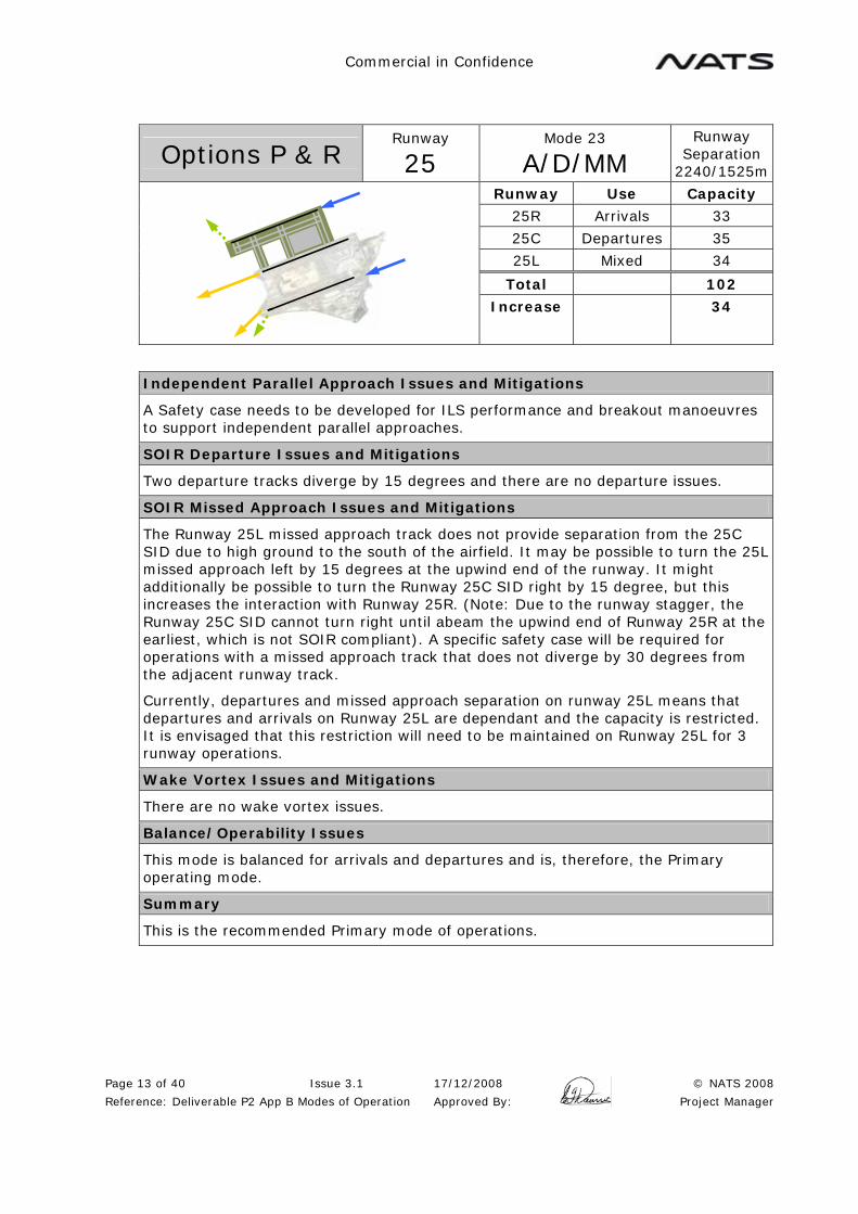
Commercial in Confidence
Page 13 of 40 Issue 3.1 17/12/2008 © NATS 2008
Reference: Deliverable P2 App B Modes of Operation Approved By: Project Manager
Options P & R Runway
25 Mode 23
A/D/MM Runway
Separation 2240/1525m
Runway Use Capacity
25R Arrivals 33
25C Departures 35
25L Mixed 34
Total 102
Increase 34
Independent Parallel Approach Issues and Mitigations
A Safety case needs to be developed for ILS performance and breakout manoeuvres to support independent parallel approaches.
SOIR Departure Issues and Mitigations
Two departure tracks diverge by 15 degrees and there are no departure issues.
SOIR Missed Approach Issues and Mitigations
The Runway 25L missed approach track does not provide separation from the 25C SID due to high ground to the south of the airfield. It may be possible to turn the 25L missed approach left by 15 degrees at the upwind end of the runway. It might additionally be possible to turn the Runway 25C SID right by 15 degree, but this increases the interaction with Runway 25R. (Note: Due to the runway stagger, the Runway 25C SID cannot turn right until abeam the upwind end of Runway 25R at the earliest, which is not SOIR compliant). A specific safety case will be required for operations with a missed approach track that does not diverge by 30 degrees from the adjacent runway track.
Currently, departures and missed approach separation on runway 25L means that departures and arrivals on Runway 25L are dependant and the capacity is restricted. It is envisaged that this restriction will need to be maintained on Runway 25L for 3 runway operations.
Wake Vortex Issues and Mitigations
There are no wake vortex issues.
Balance/Operability Issues
This mode is balanced for arrivals and departures and is, therefore, the Primary operating mode.
Summary
This is the recommended Primary mode of operations.
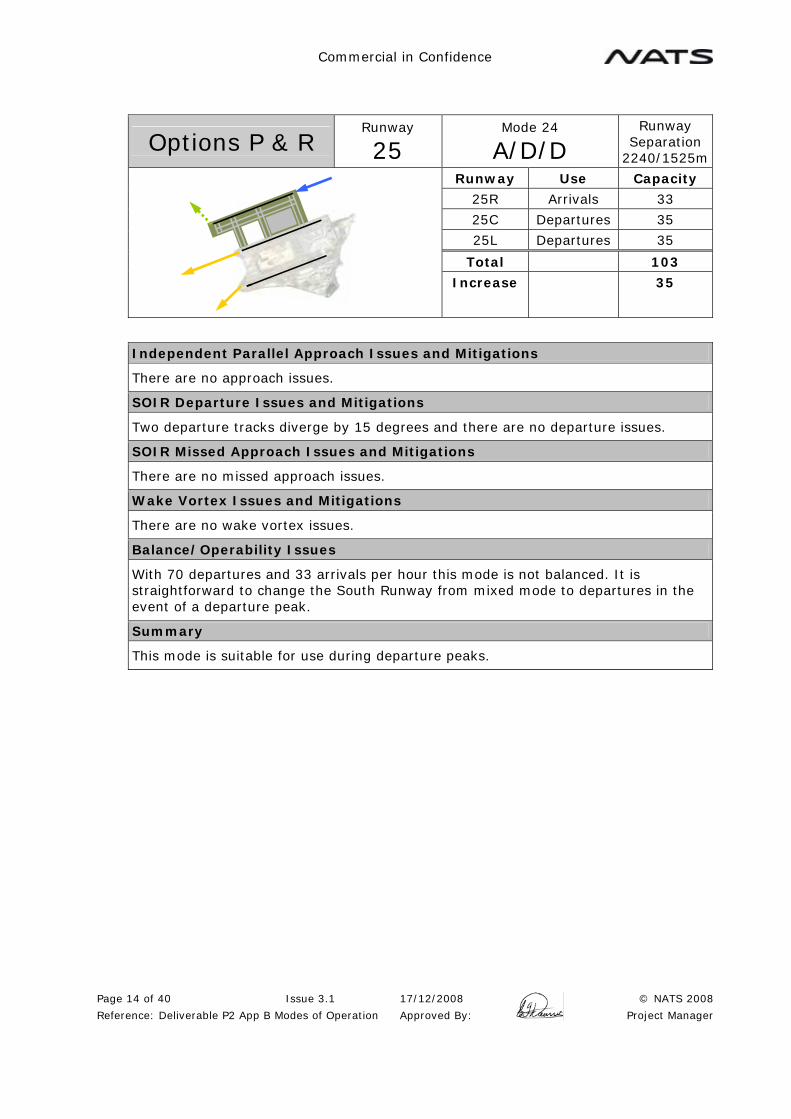
Commercial in Confidence
Page 14 of 40 Issue 3.1 17/12/2008 © NATS 2008
Reference: Deliverable P2 App B Modes of Operation Approved By: Project Manager
Options P & R Runway
25 Mode 24
A/D/D Runway
Separation 2240/1525m
Runway Use Capacity
25R Arrivals 33
25C Departures 35
25L Departures 35
Total 103
Increase 35
Independent Parallel Approach Issues and Mitigations
There are no approach issues.
SOIR Departure Issues and Mitigations
Two departure tracks diverge by 15 degrees and there are no departure issues.
SOIR Missed Approach Issues and Mitigations
There are no missed approach issues.
Wake Vortex Issues and Mitigations
There are no wake vortex issues.
Balance/Operability Issues
With 70 departures and 33 arrivals per hour this mode is not balanced. It is straightforward to change the South Runway from mixed mode to departures in the event of a departure peak.
Summary
This mode is suitable for use during departure peaks.
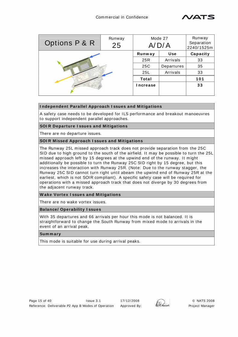
Commercial in Confidence
Page 15 of 40 Issue 3.1 17/12/2008 © NATS 2008
Reference: Deliverable P2 App B Modes of Operation Approved By: Project Manager
Options P & R Runway
25 Mode 27
A/D/A Runway
Separation 2240/1525m
Runway Use Capacity
25R Arrivals 33
25C Departures 35
25L Arrivals 33
Total 101
Increase 33
Independent Parallel Approach Issues and Mitigations
A safety case needs to be developed for ILS performance and breakout manoeuvres to support independent parallel approaches.
SOIR Departure Issues and Mitigations
There are no departure issues.
SOIR Missed Approach Issues and Mitigations
The Runway 25L missed approach track does not provide separation from the 25C SID due to high ground to the south of the airfield. It may be possible to turn the 25L missed approach left by 15 degrees at the upwind end of the runway. It might additionally be possible to turn the Runway 25C SID right by 15 degree, but this increases the interaction with Runway 25R. (Note: Due to the runway stagger, the Runway 25C SID cannot turn right until abeam the upwind end of Runway 25R at the earliest, which is not SOIR compliant). A specific safety case will be required for operations with a missed approach track that does not diverge by 30 degrees from the adjacent runway track.
Wake Vortex Issues and Mitigations
There are no wake vortex issues.
Balance/Operability Issues
With 35 departures and 66 arrivals per hour this mode is not balanced. It is straightforward to change the South Runway from mixed mode to arrivals in the event of an arrival peak.
Summary
This mode is suitable for use during arrival peaks.

Commercial in Confidence
Page 16 of 40 Issue 3.1 17/12/2008 © NATS 2008
Reference: Deliverable P2 App B Modes of Operation Approved By: Project Manager
Options P & R Runway
07 Mode 8
MM/A/D Runway
Separation 2240/1525m
Runway Use Capacity
07L Mixed 44
07C Arrivals 33
07R Departures 35
Total 112
Increase 44
Independent Parallel Approach Issues and Mitigations
A safety case needs to be developed for ILS performance and breakout manoeuvres to support independent parallel approaches.
SOIR Departure Issues and Mitigations
Two departure tracks diverge by 15 degrees and there are no departure issues. Note: A SID from Runway 07L with a 30 degree turn is in direct conflict with the Shenzhen circuit. Unless this confliction can be resolved, this mode is not viable (see below).
SOIR Missed Approach Issues and Mitigations
The Runway 07C missed approach track does not provide separation from the 07R SID due to high ground to the south of the airfield. It may be possible to turn the 25C missed approach left by 30 degrees, but this will increase the interaction with Runway 07L.
To achieve full SOIR compliance, the Runway 07L SID would be required to turn left by 60 degrees to provide separation from the Runway 07C missed approach. This, together with the high climb gradient required, is not felt to be viable. In any case, the Runway 07L SID is required to turn left be at least 30 degrees, and this creates an unacceptable conflict with the Shenzhen circuit. (See below). The Runway 07L and Runway 07C SID and missed approaches turn in the same direction, which is not SOIR compliant.
A specific safety case will be required for operations with a missed approach track that does not diverge by 30 degrees from the adjacent runway track, or where the tracks turn in the same direction.
Wake Vortex Issues and Mitigations
There are no wake vortex issues.
Balance/Operability Issues
This mode is balanced for arrivals and departures and is, therefore, a Primary operating mode.
Summary
This mode is rejected due to parallel approach issues, Centre Runway missed approach and departure issues.

Commercial in Confidence
Page 17 of 40 Issue 3.1 17/12/2008 © NATS 2008
Reference: Deliverable P2 App B Modes of Operation Approved By: Project Manager
Options P & R Runway
07 Mode 9
MM/D/A Runway
Separation 2240/1525m
Runway Use Capacity
07L Mixed 44
07C Departures 35
07R Arrivals 33
Total 112
Increase 44
Independent Parallel Approach Issues and Mitigations
A safety case needs to be developed for ILS performance and breakout manoeuvres to support independent parallel approaches.
SOIR Departure Issues and Mitigations
Two departure tracks diverge by 15 degrees and there are no departure issues. Note: A SID from Runway 07L with a 30 degree turn is in direct conflict with the Shenzhen circuit. Unless this confliction can be resolved, this mode is not viable (see below).
SOIR Missed Approach Issues and Mitigations
The Runway 07R missed approach track does not provide separation from the Runway 07C SID due to high ground to the south of the airfield. It is possible to turn the Runway 07C SID left by more than 15 degrees, but this increases the interaction with Runway 07L. The Runway 07C and 07L SID and missed approach turn in the same direction, which is not SOIR compliant. A specific safety case will be required for operations with a missed approach track that does not diverge by 30 degrees from the adjacent runway track or where the tracks turn in the same direction.
The 135 degree missed approach from Runway 07L is recommended to provide separation from the Runway 07L SID and avoid a conflict with the Shenzhen circuit.
Wake Vortex Issues and Mitigations
There are no wake vortex issues.
Balance/Operability Issues
This mode is balanced for arrivals and departures and is, therefore, a Primary operating mode.
Summary
This mode would offer the maximum capacity but has been rejected due to the confliction with the Shenzhen circuit and departure crossover issues (see below).

Commercial in Confidence
Page 18 of 40 Issue 3.1 17/12/2008 © NATS 2008
Reference: Deliverable P2 App B Modes of Operation Approved By: Project Manager
Interaction with Shenzhen Circuit
Mode 8 uses the North Runway for departure and Mode 9 uses the North and Centre Runways for departure. In the Runway 07 direction, the Runway 07C SID turns left by at least 15 degrees to achieve separation from the Runway 07R missed approach and to allow a reduced climb gradient up the Tai Lam valley. The Runway 07L SID is then required to turn left by at least 30 degrees. These values assume that the required safety cases are in place for non-SOIR compliant separations. It is possible that even larger turns might be required. These SIDs in Modes 8 and 9 create significant operational issues in respect of the Shenzhen circuit.
The Shenzhen circuit, whether operating in segregated or mixed mode, creates a significant interaction with any proposed Hong Kong North Circuit, including departures and missed approaches to the north. It is possible to design a 15 degree SID with 5NM separation from the circuit, but modelling indicates that the traffic passes abeam at roughly the same altitude (3000ft to 4000ft), requiring a careful procedure design.
A 30 degree (or greater) SID from Runway 07L will pass underneath the Shenzhen circuit. With the circuit at 3000ft, the Hong Kong outbound would have to maintain 2000ft for a considerable distance and this may create terrain clearance issues. If the circuit is designed with a high side and a low side, this would still restrict the Hong Kong departure to 3000ft, and additionally create a significant level bust hazard, with the departing traffic levelling off below the Shenzhen circuit traffic.
Other options, such as increasing the Shenzhen circuit height to 5000ft or 6000ft would extend the Shenzhen final overhead Hong Kong. This then creates other problems, such as a conflict with the Runway 07R missed approach, which is required to climb to 4500ft as a minimum due to terrain clearance.
Figure 3.1 Interaction with Shenzhen Circuit
4000ft
3000ft
3000ft
2000ft
5000ft 9000ft 5NM

Commercial in Confidence
Page 19 of 40 Issue 3.1 17/12/2008 © NATS 2008
Reference: Deliverable P2 App B Modes of Operation Approved By: Project Manager
Departure Issues in Mode 9
The SIDs in Mode 9 create further operational problems due to the fact that southbound departures initially have to route to the north.
In Mode 9, southbound departures use Runway 07C. The SID turns left initially, and would be required to route to the South at some point, crossing the inbound stream. This would either require the departures to maintain 9000ft for a long period, or require extended routings to climb above inbound traffic. The varying climb rates of the departing aircraft makes these crossovers difficult.
The interaction with the Shenzhen circuit and these departure issues means that Mode 8 and Mode 9 are considered not to be viable.
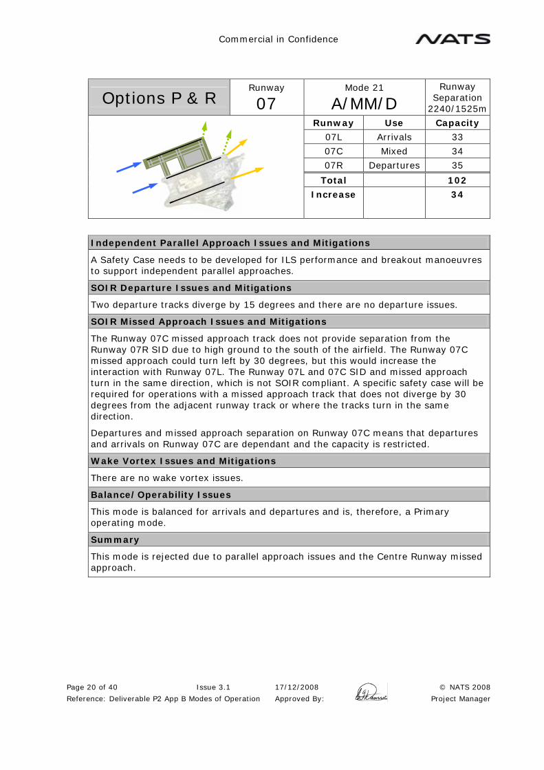
Commercial in Confidence
Page 20 of 40 Issue 3.1 17/12/2008 © NATS 2008
Reference: Deliverable P2 App B Modes of Operation Approved By: Project Manager
Options P & R Runway
07 Mode 21
A/MM/D Runway
Separation 2240/1525m
Runway Use Capacity
07L Arrivals 33
07C Mixed 34
07R Departures 35
Total 102
Increase 34
Independent Parallel Approach Issues and Mitigations
A Safety Case needs to be developed for ILS performance and breakout manoeuvres to support independent parallel approaches.
SOIR Departure Issues and Mitigations
Two departure tracks diverge by 15 degrees and there are no departure issues.
SOIR Missed Approach Issues and Mitigations
The Runway 07C missed approach track does not provide separation from the Runway 07R SID due to high ground to the south of the airfield. The Runway 07C missed approach could turn left by 30 degrees, but this would increase the interaction with Runway 07L. The Runway 07L and 07C SID and missed approach turn in the same direction, which is not SOIR compliant. A specific safety case will be required for operations with a missed approach track that does not diverge by 30 degrees from the adjacent runway track or where the tracks turn in the same direction.
Departures and missed approach separation on Runway 07C means that departures and arrivals on Runway 07C are dependant and the capacity is restricted.
Wake Vortex Issues and Mitigations
There are no wake vortex issues.
Balance/Operability Issues
This mode is balanced for arrivals and departures and is, therefore, a Primary operating mode.
Summary
This mode is rejected due to parallel approach issues and the Centre Runway missed approach.

Commercial in Confidence
Page 21 of 40 Issue 3.1 17/12/2008 © NATS 2008
Reference: Deliverable P2 App B Modes of Operation Approved By: Project Manager
Options P & R Runway
07 Mode 23
A/D/MM Runway
Separation 2240/1525m
Runway Use Capacity
07L Arrivals 33
07C Departures 35
07R Mixed 34
Total 102
Increase 34
Independent Parallel Approach Issues and Mitigations
A Safety Case needs to be developed for ILS performance and breakout manoeuvres to support independent parallel approaches.
SOIR Departure Issues and Mitigations
Two departure tracks diverge by 15 degrees and there are no departure issues.
SOIR Missed Approach Issues and Mitigations
The Runway 07R missed approach track does not provide separation from the Runway 07C SID due to high ground to the south of the airfield. It may be possible to turn the Runway 07C SID left by 30 degrees but this increases the interaction with the Runway 07L missed approach. The Runway 07L missed approach and the Runway 07C SID turn in the same direction. A specific safety case will be required for operations with a missed approach track that does not diverge by 30 degrees from the adjacent runway track or where the tracks turn in the same direction.
The 135 degree missed approach from Runway 07L is recommended for separation from the Runway 07C SID and to avoid a conflict with the Shenzhen circuit.
Currently, departures and missed approach separation on Runway 07R means that departures and arrivals on Runway 07R are dependant and the capacity is restricted. It is envisaged that this restriction will need to be maintained on Runway 07R for 3 runway operations.
Wake Vortex Issues and Mitigations
There are no wake vortex issues.
Balance/Operability Issues
This mode is balanced for arrivals and departures and is, therefore, the Primary operating mode.
Summary
This mode is the recommended Primary mode of operations.

Commercial in Confidence
Page 22 of 40 Issue 3.1 17/12/2008 © NATS 2008
Reference: Deliverable P2 App B Modes of Operation Approved By: Project Manager
Options P & R Runway
07 Mode 24
A/D/D Runway
Separation 2240/1525m
Runway Use Capacity
07L Arrivals 33
07C Departures 35
07R Departures 35
Total 103
Increase 35
Independent Parallel Approach Issues and Mitigations
There are no approach issues.
SOIR Departure Issues and Mitigations
Two departure tracks diverge by 15 degrees and there are no departure issues.
SOIR Missed Approach Issues and Mitigations
There are no missed approach issues.
The 135 degree missed approach from Runway 07L is recommended for separation from the Runway 07C SID and to avoid a conflict with the Shenzhen circuit.
Wake Vortex Issues and Mitigations
There are no wake vortex issues.
Balance/Operability Issues
With 70 departures and 33 arrivals per hour this mode is not balanced. It is straightforward to change the South Runway from mixed mode to departures in the event of a departure peak.
Summary
This mode is suitable for use during departure peaks.

Commercial in Confidence
Page 23 of 40 Issue 3.1 17/12/2008 © NATS 2008
Reference: Deliverable P2 App B Modes of Operation Approved By: Project Manager
Options P & R Runway
07 Mode 27
A/D/A Runway
Separation 2240/1525m
Runway Use Capacity
07L Arrivals 33
07C Departures 35
07R Arrivals 33
Total 101
Increase 33
Independent Parallel Approach Issues and Mitigations
A Safety Case needs to be developed for ILS performance and breakout manoeuvres to support independent parallel approaches.
SOIR Departure Issues and Mitigations
There are no departure issues.
SOIR Missed Approach Issues and Mitigations
The Runway 07R missed approach track does not provide separation from the Runway 07C SID due to high ground to the South of the airfield. It may be possible to turn the Runway 07C SID left by 30 degrees but this increases the interaction with the Runway 07L missed approach. The Runway 07L missed approach and the Runway 07C SID turn in the same direction. A specific safety case will be required for operations with a missed approach track that does not diverge by 30 degrees from the adjacent runway track or where the tracks turn in the same direction.
The 135 degree missed approach from Runway 07L is recommended for separation from the Runway 07C SID and to avoid a conflict with the Shenzhen circuit.
Wake Vortex Issues and Mitigations
There are no wake vortex issues.
Balance/Operability Issues
With 35 departures and 66 arrivals per hour this mode is not balanced. It is straightforward to change the South Runway from mixed mode to arrivals in the event of an arrival peak.
Summary
This mode is suitable for use during arrival peaks.
Commercial in Confidence
Page 24 of 40 Issue 3.1 17/12/2008 © NATS 2008
Reference: Deliverable P2 App B Modes of Operation Approved By: Project Manager
3.2 Option S Extended (All Variants)
The possible modes of operation for Option S Extended (All Variants) has been reviewed and the results are summarised in Table 2.2 above.
Modes 23, 24 and 27 have been selected for detailed investigation.

Commercial in Confidence
Page 25 of 40 Issue 3.1 17/12/2008 © NATS 2008
Reference: Deliverable P2 App B Modes of Operation Approved By: Project Manager
Option S Ext All Variants
Runway
25 Mode 23
A/D/MM Runway
Separation 380m
Evaluation assumes that Runways 25R & 25C threshold stagger is sufficient for segregated operations.
Threshold stagger should be 1950m or have valid safety case for reduced stagger.
Runway Use Capacity
25R Arrivals 33
25C Departures 35
25L Mixed 34
Total 102
Increase 34
Independent Parallel Approach Issues and Mitigations
A safety case needs to be developed for ILS performance and breakout manoeuvres to support independent parallel approaches.
SOIR Departure Issues and Mitigations
Two departure tracks diverge by 15 degrees and there are no departure issues.
SOIR Missed Approach Issues and Mitigations
The Runway 25L missed approach track does not provide separation from the 25C SID due to high ground to the South of the airfield. It may be possible to turn the 25L missed approach left by 15 degrees at the upwind end of the runway. A specific safety case will be required for operations with a missed approach track that does not diverge by 30 degrees from the adjacent runway track.
Currently, departures and missed approach separation on runway 25L means that departures and arrivals on Runway 25L are dependant and the capacity is restricted. It is envisaged that this restriction will need to be maintained on Runway 25L for 3 runway operations.
Wake Vortex Issues and Mitigations
Traffic operating on Runway 25R is separated for the purposes of vortex wake from traffic operating on Runway 25L.
Traffic operating on Runway 25C is separated for the purposes of vortex wake from traffic operating on Runway 25L.
Runway 25R/25C requires wake vortex separation in the event of a Heavy missed approach.
Balance/Operability Issues
This mode is balanced for arrivals and departures.
Summary
This mode is the recommended Primary mode of operations.

Commercial in Confidence
Page 26 of 40 Issue 3.1 17/12/2008 © NATS 2008
Reference: Deliverable P2 App B Modes of Operation Approved By: Project Manager
Option S Ext All Variants
Runway
25 Mode 24
A/D/D Runway
Separation 380m
Evaluation assumes that Runways 25R & 25C threshold stagger is sufficient for segregated operations.
Threshold stagger should be 1950m or have valid safety case for reduced stagger.
Runway Use Capacity
25R Arrivals 33
25C Departures 35
25L Departures 35
Total 103
Increase 35
Independent Parallel Approach Issues and Mitigations
With a single arrival stream there are no parallel approach issues.
SOIR Departure Issues and Mitigations
Two departure tracks diverge by 15 degrees and there are no departure issues.
SOIR Missed Approach Issues and Mitigations
None
Wake Vortex Issues and Mitigations
Runway 25R/25C requires wake vortex separation in the event of a Heavy Missed Approach.
Balance/Operability Issues
With 70 departures and 33 arrivals per hour this mode is not balanced. It is straightforward to change the South Runway from mixed mode to departures in the event of a departure peak.
Summary
This mode is suitable for use during departure peaks.

Commercial in Confidence
Page 27 of 40 Issue 3.1 17/12/2008 © NATS 2008
Reference: Deliverable P2 App B Modes of Operation Approved By: Project Manager
Option S Ext All Variants
Runway
25 Mode 27
A/D/A Runway
Separation 380m
Evaluation assumes that Runways 25R & 25C threshold stagger is sufficient for segregated operations.
Threshold stagger should be 1950m or have valid safety case for reduced stagger.
Runway Use Capacity
25R Arrivals 33
25C Departures 35
25L Arrivals 33
Total 101
Increase 33
Independent Parallel Approach Issues and Mitigations
A safety case needs to be developed for ILS performance and breakout manoeuvres to support independent parallel approaches.
SOIR Departure Issues and Mitigations
With a single departure stream there are no departure issues.
SOIR Missed Approach Issues and Mitigations
The Runway 25L missed approach track does not provide separation from the Runway 25C SID due to high ground to the South of the airfield. It may be possible to turn the Runway 25L missed approach left by 15 degrees at the upwind end of the runway. A specific safety case will be required for operations with a missed approach track that does not diverge by 30 degrees from the runway track.
Wake Vortex Issues and Mitigations
Runway 25R/25C requires wake vortex separation in the event of a Heavy missed approach.
Balance/Operability Issues
With 35 departures and 66 arrivals per hour this mode is not balanced. It is straightforward to change the South Runway from mixed mode to arrivals in the event of an arrival peak.
Summary
This mode is suitable for use during arrival peaks.

Commercial in Confidence
Page 28 of 40 Issue 3.1 17/12/2008 © NATS 2008
Reference: Deliverable P2 App B Modes of Operation Approved By: Project Manager
Option S Ext All Variants
Runway
25 Mode 23
A/D/MM Runway
Separation 380m
NOT SOIR COMPLIANT DUE THRESHOLD STAGGER AND BREAKOUT
Evaluation assumes that Runways 25R & 25C threshold stagger is less than 1950m.
With a threshold stagger of less than 1950m and a proven safety case does not exist then runway 25R and runway 25C must be dependent.
Runway Use Capacity
25R Arrivals 31 (26)
25C Departures 26 (21)
25L Mixed 31 (26)
Total 88 (83)
Increase 20 (15)
Independent Parallel and Dependent Approach Issues and Mitigations
A safety case needs to be developed for ILS performance and breakout manoeuvres to support independent parallel approaches. Assuming that the breakout manoeuvre does not support parallel approaches, procedures for ICAO compliant dependant approaches are required (See ATC procedure section below). The arrival rate on Runway 25R is reduced to a capacity of 31 due to the dependence of 25R and 25L. This reduces the total mixed mode capacity on Runway 25L to 31.
SOIR Departure Issues and Mitigations
Two departure tracks diverge by 15 degrees and there are no departure issues.
Due to the lack of threshold stagger, the Runway 25C departure is dependant on the Runway 25R arrival. In order to maintain the required separation, the Runway 25C departure must be at least 950m down the runway by the time the Runway 25R arrival crosses the Runway 25R threshold. In order to achieve this, the departure must commence the take off roll before the arrival passes 2NM from touchdown. The minimum final approach spacing on Runway 25R is 4NM. These procedures limit the arrival rate on 25R to 31. If all the departures on Runway 25C are 90 seconds, then the departure rate would also be 31. The arrival rate on 25R in less than 120 seconds, therefore for every wake vortex 2 minute departure separation, a departure slot would be lost. If this occurs 5 times in an hour, the departure rate is further reduced to 26.
SOIR Missed Approach Issues and Mitigations
The Runway 25L missed approach track does not provide separation from the Runway 25C SID due to high ground to the South of the airfield. It may be possible to turn the Runway 25L missed approach left by 15 degrees at the upwind end of the runway. A specific safety case will be required for operations with a missed approach track that does not diverge by 30 degrees from the runway track. If the arrival on Runway 25L and the departure on Runway 25C were to be considered dependant because of this issue, the capacity would be further reduced. This would also create the situation where the departure was dependant on the arrivals to two runways. It is considered that this would be unacceptable complex and would result in this runway option being unworkable.

Commercial in Confidence
Page 29 of 40 Issue 3.1 17/12/2008 © NATS 2008
Reference: Deliverable P2 App B Modes of Operation Approved By: Project Manager
Currently, departures and missed approach separation on Runway 25L means that departures and arrivals on Runway 25L are dependant and the capacity is restricted. It is envisaged that this restriction will need to be maintained on Runway 25L for 3 runway operations.
Wake Vortex Issues and Mitigations
Traffic operating on Runway 25R is separated for the purposes of vortex wake from traffic operating on Runway 25L.
Traffic operating on Runway 25C is separated for the purposes of vortex wake from traffic operating on Runway 25L.
Runway 25R/25C requires wake vortex separation in the event of a Heavy missed approach. This criterion is considered to be met by the fact that arrivals and departures are dependant (See departure section above).
Figure 3.2 SOIR Compliant Arrival/Departure Separation
Figure 3.3 Proposed Arrival/Departure Separation at Take Off for Option S Extended (Variants D and E). Departure commences take off roll before an inbound reaches 2NM.
380m
1000m
Threshold Runway 25C
Threshold Runway 25R
2NM
950m
380m
1950m
Threshold Runway 25C
Threshold Runway 25R

Commercial in Confidence
Page 30 of 40 Issue 3.1 17/12/2008 © NATS 2008
Reference: Deliverable P2 App B Modes of Operation Approved By: Project Manager
Figure 3.4 Arrival/Departure Separation is Achieved at Touchdown for Option S Extended (Variants D and E). Departure at least 950m down the runway when the inbound crosses the threshold.
Figure 3.5 Proposed Arrival/Departure Separation for Options S Extended (Variants A, B and C). Departure commences take off roll before an inbound reaches 3NM.
Figure 3.6 Arrival/Departure Separation is achieved at touchdown for Option S Extended (Variants A, B and C). Departure at least 1950m down the runway when the inbound crosses the threshold.
380m
1950m
Threshold Runway 25C/25R 3NM
Threshold Runway 25C/25R 3NM
1950m
380m
380m
1000m
Threshold Runway 25C
Threshold Runway 25R
2NM
950m
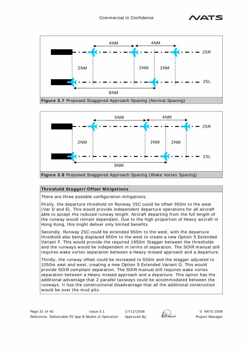
Commercial in Confidence
Page 31 of 40 Issue 3.1 17/12/2008 © NATS 2008
Reference: Deliverable P2 App B Modes of Operation Approved By: Project Manager
Figure 3.7 Proposed Staggered Approach Spacing (Normal Spacing)
Figure 3.8 Proposed Staggered Approach Spacing (Wake Vortex Spacing)
Threshold Stagger/Offset Mitigations
There are three possible configuration mitigations.
Firstly, the departure threshold on Runway 25C could be offset 950m to the west (Var D and E). This would provide independent departure operations for all aircraft able to accept the reduced runway length. Aircraft departing from the full length of the runway would remain dependant. Due to the high proportion of Heavy aircraft in Hong Kong, this might deliver only limited benefits.
Secondly, Runway 25C could be extended 950m to the west, with the departure threshold also being displaced 950m to the west to create a new Option S Extended Variant F. This would provide the required 1950m Stagger between the thresholds and the runways would be independent in terms of separation. The SOIR manual still requires wake vortex separation between a Heavy missed approach and a departure.
Thirdly, the runway offset could be increased to 550m and the stagger adjusted to 1050m east and west, creating a new Option S Extended Variant G. This would provide SOIR compliant separation. The SOIR manual still requires wake vortex separation between a Heavy missed approach and a departure. This option has the additional advantage that 2 parallel taxiways could be accommodated between the runways. It has the constructional disadvantage that all the additional construction would be over the mud pits.
25R
2NM 2NM
8NM
2NM
4NM 4NM
25L
2NM 2NM 2NM
25L
25R
5NM 4NM
9NM

Commercial in Confidence
Page 32 of 40 Issue 3.1 17/12/2008 © NATS 2008
Reference: Deliverable P2 App B Modes of Operation Approved By: Project Manager
Figure 3.9 Aircraft Departing from an Intersection 950m from the Threshold are Independent
Figure 3.10 Proposed S Extended Variant F. Identical to Variants D and E with the Centre Runway extended 950m to the west.
Figure 3.11 Proposed S Extended Variant G. New runway offset by 550m and extended 1050m to the east and west.
25
R
25
C
950m 1000m

Commercial in Confidence
Page 33 of 40 Issue 3.1 17/12/2008 © NATS 2008
Reference: Deliverable P2 App B Modes of Operation Approved By: Project Manager
Balance/Operability Issues
This mode is balanced for arrivals and departures and is, therefore, the Primary operating mode.
The lack of threshold stagger (less than 1950m) makes the Northern pair of runways dependant, limiting the arrival rate to 31 (26 for Variants A, B and C) and the departure rate to 26 (21 for Variants A, B and C). The need for dependent approaches limits the capacity of the southern runway to 31 in mixed mode (26 for Variants A, B and C).
If the arrival on Runway 25L and the departure on Runway 25C were to be considered dependant due to the lack of 30 degree of track separation, it is considered that this mode would be unacceptably complex and this runway option would be unworkable.
Other mitigations that might be considered are the use of intersection departures, to extend Runway 25C 950m to the west and achieve a SOIR complaint threshold stagger by displacing the departure threshold. Increasing the runway offset to 550m and the threshold stagger to 1050m would also be SOIR compliant.
Summary
The SOIR compliance issues with Option S Extended Variants D and E in the Runway 25 direction cause operational problems and place significant capacity constraints on these Options. It is recommended that further consideration of Option S Extended should be based on Variant F. The dependency of the Runway 25L and 25R approaches limit the capacity of Option S Extended (All Variants).
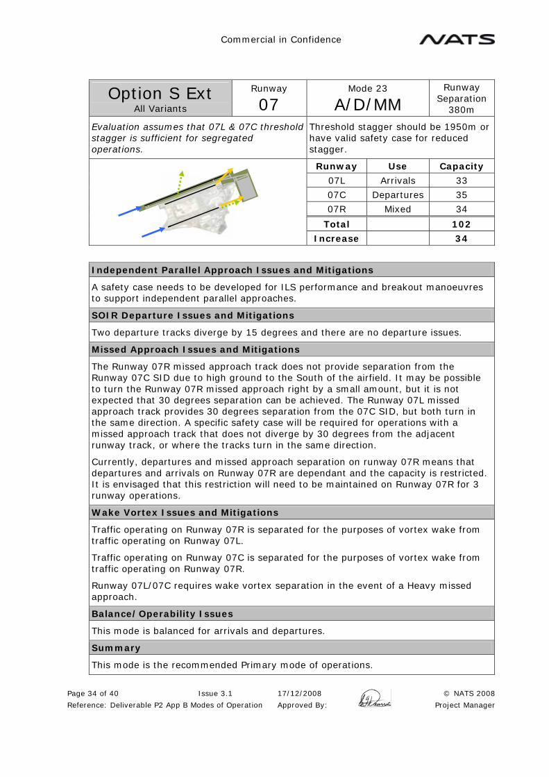
Commercial in Confidence
Page 34 of 40 Issue 3.1 17/12/2008 © NATS 2008
Reference: Deliverable P2 App B Modes of Operation Approved By: Project Manager
Option S Ext All Variants
Runway
07 Mode 23
A/D/MM Runway
Separation 380m
Evaluation assumes that 07L & 07C threshold stagger is sufficient for segregated operations.
Threshold stagger should be 1950m or have valid safety case for reduced stagger.
Runway Use Capacity
07L Arrivals 33
07C Departures 35
07R Mixed 34
Total 102 Increase 34
Independent Parallel Approach Issues and Mitigations
A safety case needs to be developed for ILS performance and breakout manoeuvres to support independent parallel approaches.
SOIR Departure Issues and Mitigations
Two departure tracks diverge by 15 degrees and there are no departure issues.
Missed Approach Issues and Mitigations
The Runway 07R missed approach track does not provide separation from the Runway 07C SID due to high ground to the South of the airfield. It may be possible to turn the Runway 07R missed approach right by a small amount, but it is not expected that 30 degrees separation can be achieved. The Runway 07L missed approach track provides 30 degrees separation from the 07C SID, but both turn in the same direction. A specific safety case will be required for operations with a missed approach track that does not diverge by 30 degrees from the adjacent runway track, or where the tracks turn in the same direction.
Currently, departures and missed approach separation on runway 07R means that departures and arrivals on Runway 07R are dependant and the capacity is restricted. It is envisaged that this restriction will need to be maintained on Runway 07R for 3 runway operations.
Wake Vortex Issues and Mitigations
Traffic operating on Runway 07R is separated for the purposes of vortex wake from traffic operating on Runway 07L.
Traffic operating on Runway 07C is separated for the purposes of vortex wake from traffic operating on Runway 07R.
Runway 07L/07C requires wake vortex separation in the event of a Heavy missed approach.
Balance/Operability Issues
This mode is balanced for arrivals and departures.
Summary
This mode is the recommended Primary mode of operations.

Commercial in Confidence
Page 35 of 40 Issue 3.1 17/12/2008 © NATS 2008
Reference: Deliverable P2 App B Modes of Operation Approved By: Project Manager
Options S Ext All Variants
Runway
07 Mode 24
A/D/D Runway
Separation 380m
Evaluation assumes that 07L & 07C threshold stagger is sufficient for segregated operations.
Threshold stagger should be 1950m or have valid safety case for reduced stagger.
Runway Use Capacity
07L Arrivals 33
07C Departures 35
07R Departures 35
Total 103 Increase 35
Independent Parallel Approach Issues and Mitigations
With a single arrival stream there are no parallel approach issues.
SOIR Departure Issues and Mitigations
Two departure tracks diverge by 15 degrees and there are no departure issues.
Missed Approach Issues and Mitigations
The Runway 07L missed approach track provides 30 degrees separation from the 07C SID, but both turn in the same direction.
Wake Vortex Issues and Mitigations
Runway 07L/07C requires wake vortex separation in the event of a Heavy missed approach.
Balance/Operability Issues
With 70 departures and 33 arrivals per hour this mode is not balanced. It is straightforward to change the South Runway from mixed mode to departures in the event of a departure peak.
Summary
This mode is suitable for use during departure peaks.

Commercial in Confidence
Page 36 of 40 Issue 3.1 17/12/2008 © NATS 2008
Reference: Deliverable P2 App B Modes of Operation Approved By: Project Manager
Option S Ext All Variants
Runway
07 Mode 27
A/D/A Runway
Separation 380m
Evaluation assumes that 07L & 07C threshold stagger is sufficient for segregated operations.
Threshold stagger should be 1950m or have valid safety case for reduced stagger.
Runway Use Capacity
07L Arrivals 33
07C Departures 35
07R Arrivals 33
Total 101 Increase 33
Independent Parallel Approach Issues and Mitigations
A safety case needs to be developed for ILS performance and breakout manoeuvres to support parallel and/or staggered approaches.
SOIR Departure Issues and Mitigations
With a single departure stream there are no departure issues.
Missed Approach Issues and Mitigations
The Runway 07R missed approach track does not provide separation from the 07C SID due to high ground to the South of the airfield. It may be possible to turn the 07R missed approach right by a small amount, but it is not expected that 30 degrees separation can be achieved.
The Runway 07L missed approach track provides 30 degrees separation from the 07C SID, but both turn in the same direction.
A specific safety case will be required for operations with a missed approach track that does not diverge by 30 degrees from the adjacent runway track or where the tracks turn in the same direction.
Wake Vortex Issues and Mitigations
Runway 07L/07C requires wake vortex separation in the event of a Heavy missed approach.
Balance/Operability Issues
With 35 departures and 66 arrivals per hour this mode is not balanced. It is straightforward to change the South Runway from mixed mode to arrivals in the event of an arrival peak.
Summary
This mode is suitable for use during arrival peaks.

Commercial in Confidence
Page 37 of 40 Issue 3.1 17/12/2008 © NATS 2008
Reference: Deliverable P2 App B Modes of Operation Approved By: Project Manager
Option S Ext All Variants
Runway
07 Mode 23
A/D/MM Runway
Separation 380m
NOT SOIR COMPLIANT DUE 07C SID vs. 07R MISSED APPROACH AND BREAKOUT
Evaluation assumes that 07L & 07C threshold stagger is compliant.
The most significant issue is the 07C SID vs. 07R missed approach
With 15 degrees separation between the 07C SID and 07R missed approach if a proven safety case does not exist then runway 07C and runway 07R must be dependent.
Runway Use Capacity
07L Arrivals 33 (31)
07C Departures 29 (26)
07R Mixed 34 (31)
Total 96 (88) Increase 28 (20)
Independent Parallel Approach Issues and Mitigations
A safety case needs to be developed for ILS performance and breakout manoeuvres to support independent parallel approaches. Assuming that the breakout manoeuvre does not support independent parallel approaches, procedures for dependant approaches are required (See ATC procedure section below). The arrival rate on Runway 07L is reduced to a capacity of 31 due to the dependence of 07L and 07R. This reduces the total mixed mode capacity on Runway 07R to 31.
SOIR Departure Issues and Mitigations
The two departure tracks diverge by 15 degrees and there are no departure issues.
Missed Approach Issues and Mitigations
The Runway 07R missed approach track does not provide separation from the Runway 07C SID due to high ground to the South of the airfield. It may be possible to turn the Runway 07R missed approach right by a small amount, but it is not expected that 30 degrees separation can be achieved. A specific safety case will be required for operations with a missed approach track that does not diverge by 30 degrees from the runway track. If the arrival on Runway 07R and the departure on Runway 07C were to be considered dependant because of this issue, the capacity would be reduced. If an additional dependence was also required in the case of a Heavy missed approach from Runway 07L, this would also create the situation where the departure was dependant on the arrivals to two runways. It is considered that this would be unacceptably complex and would result in this runway option being unworkable.
The Runway 07L missed approach track provides 30 degrees separation from the 07C SID, but both turn in the same direction.
Currently, departures and missed approach separation on Runway 25L means that departures and arrivals on Runway 25L are dependant and the capacity is restricted. It is envisaged that this restriction will need to be maintained on Runway 25L for 3 runway operations.

Commercial in Confidence
Page 38 of 40 Issue 3.1 17/12/2008 © NATS 2008
Reference: Deliverable P2 App B Modes of Operation Approved By: Project Manager
Wake Vortex Issues and Mitigations
Traffic operating on 07R is separated for the purposes of vortex wake from traffic operating on 07L.
Traffic operating on 07C is separated for the purposes of vortex wake from traffic operating on 07R.
Runway 07L/07C requires wake vortex separation in the event of a Heavy missed approach.
ATC Procedures
Due to the lack of SOIR compliance, additional ATC procedures will be required to operate the Runway 07R/07C combination and some reduction in capacity will occur.
Runway 07R/07C
The Runway 07C departure must commence take off roll before any Runway 07R arrival reaches 2NM from touchdown. With 8NM spacing on Runway 07R, at 90 secs departure interval then two departures can be released in each gap. If 120 sec wake vortex is required between departures, then only 1 departure can be released in each gap. It is estimated that the 17 gaps available in the Runway 07R arrival stream, 12 could be used for 2 departures and 5 used for 1 departure, giving a total capacity of 29 departures. (See diagrams in ATC Procedures Section below).
Runway 07R/07L
Staggered approaches to Runway 07R and Runway 07L could be conducted, based on 8NM spacing on 07R and 4 mile spacing on 07L. A minimum 2NM stagger is required between aircraft of adjacent final approach tracks. Whenever wake vortex spacing greater than 4NM was required on Runway 07L, the spacing on Runway 07R would have to be increased to allow the approach streams to remain balanced, resulting in a loss of capacity on Runway 07R (See Diagrams in ATC Procedures Section below).
Both Dependencies
If both of the dependencies above are required, the arrival rate is reduced to 31 on runway 07L and Runway 07R capacity if 31 mixed mode. The dependant departure rate is re-assessed as 15 gaps available in the Runway 07R arrival stream, 11 could be used for 2 departures and 4 used for 1 departure, giving a total capacity of 26 departures.

Commercial in Confidence
Page 39 of 40 Issue 3.1 17/12/2008 © NATS 2008
Reference: Deliverable P2 App B Modes of Operation Approved By: Project Manager
Figure 3.12 Dependant Departures on Runways 07R and 07C
Figure 3.13 Proposed Staggered Approach Spacing (Normal Spacing)
Figure 3.14 Proposed Staggered Approach Spacing (Wake Vortex Spacing).
50sec
50sec 50sec
07R Arrivals
07C Departure
90sec
Time
Inbound at 2NM
Inbound at 2NM
Outbound Rolls
Outbound Rolls
196sec
2NM 2NM 2NM
07R
07L
5NM 4NM
9NM
2NM 2NM 2NM
07R
07L
4NM 4NM
8NM

Commercial in Confidence
Page 40 of 40 Issue 3.1 17/12/2008 © NATS 2008
Reference: Deliverable P2 App B Modes of Operation Approved By: Project Manager
Balance/Operability Issues
This mode is balanced for arrivals and departures and is, therefore, the Primary operating mode.
The arrival on Runway 07R and the departure on Runway 07C are dependant due to the lack of 30 degree of track separation, limiting the departure rate to 29 and the total capacity to 96. A safety case is required to operate at maximum capacity without this dependency.
If the arrival on Runway 07R and the arrival on Runway 07L require dependant staggered approaches, then the arrival capacity is reduced to 31 on Runway 07L and the mixed mode capacity on Runway 07R is 31.
Should both of these dependencies be required, then the departure rate reduces to 26 and the overall capacity to 88.
If the requirement for separation against the Heavy missed approach from Runway 07L is also required, it is considered that this mode would be unacceptable complex and this runway option would be unworkable.
Summary
The Runway 07L Heavy missed approach issue and the 15 degree SID/missed approach separation need to be resolved in order for this Option to be viable. The dependency of the Runway 07L and 07R approaches limit the capacity of Option S Extended (All Variants).

Commercial in Confidence
Page 1 of 13 Issue 3.1 17/12/2008 © NATS 2008
Reference: Deliverable P2 App C Breakouts Approved By: Project Manager
AIRSPACE AND RUNWAY CAPACITY STUDY PHASE 1b
Appendix C
Breakout Manoeuvres

Commercial in Confidence
Page 2 of 13 Issue 3.1 17/12/2008 © NATS 2008
Reference: Deliverable P2 App C Breakouts Approved By: Project Manager
CONTENTS
1 HONG KONG BREAKOUT MANOUVRE ...................................................................3 1.1 Introduction................................................................................................. 3 1.2 SOIR Manual Example ................................................................................... 3 1.3 Alternative Breakout Manoeuvres.................................................................... 4 1.4 Proposed Breakout Manoeuvre...................................................................... 10 1.5 Dependant Parallel Approaches..................................................................... 13

Commercial in Confidence
Page 3 of 13 Issue 3.1 17/12/2008 © NATS 2008
Reference: Deliverable P2 App C Breakouts Approved By: Project Manager
1 HONG KONG BREAKOUT MANOUVRE
1.1 Introduction
The SOIR manual breakout manoeuvre consists of the threatened aircraft being instructed to make an immediate turn and climb. As the turn input to the aircraft will take effect more quickly than the climb initiation, this results in the aircraft turning away from the ILS localiser while still descending and then the climbing away on a heading up to 45 degrees from the final approach track. Due to the terrain issues, this breakout manoeuvre is not suitable at Hong Kong and an alternative breakout scenario needs to be developed.
The SOIR manual example also provides sample figures for the Detection Zone, Delay Time and Correction Zone (See Appendix A). These need to be re-assessed based on the revised breakout scenario.
1.2 SOIR Manual Example
The SOIR manual example demonstrates the basic principles of the breakout manoeuvre. An aircraft is considered to have commenced blundering at the point it leaves the NTZ.
• The Detection Zone is the time taken for the blunder to be detected.
• The Delay Time is the time for the controller to decide on a course of action, contact the pilot of the threatened aircraft, pass the instructions for the breakout manoeuvre and for the crew to respond.
• The Correction Zone is the time taken for the threatened aircraft to manoeuvre.
• The Miss Distance is the lateral separation achieved at the closed point.
It must be noted that this situation is the worst case scenario. As the aircraft are randomly sequenced on the two final approach tracks, it is very likely that the critical orientation between a blundering aircraft and a threatened aircraft may not be present. In this case, the blundering aircraft may fortuitously pass through a gap in the arrival sequence on the adjacent approach track.
The SOIR manual also ignores any vertical displacement (e.g. in the event that the blundering aircraft conducts a missed approach). It is therefore likely that in addition to the horizontal miss distance, there may also be an element of vertical separation.
In summary, the SOIR manual breakout adopts three basic principles:
• It always provides a lateral miss distance (e.g. 60m) regardless of any longitudinal or vertical separation, therefore eliminating the risk of collision.
Note: This assumes that the detection, breakout instructions and the manoeuvre are completed within the target times. If these times are not achieved, then it is possible for a collision to occur.
• A standard breakout manoeuvre is used in all circumstances to simplify the procedure for pilots and controllers.
• It is assumed that the blundering aircraft cannot be turned away (e.g. due to a control problem or a radio failure).

Commercial in Confidence
Page 4 of 13 Issue 3.1 17/12/2008 © NATS 2008
Reference: Deliverable P2 App C Breakouts Approved By: Project Manager
Figure 1.1 ICAO SOIR Manual Example
1.3 Alternative Breakout Manoeuvres
A number of alternative breakout manoeuvres have been considered to address the specific situation at HKIA.
The first issue is that a turning breakout manoeuvre is not appropriate, so an investigation was undertaken into a vertical breakout manoeuvre. This would follow the SOIR principle that the threatened aircraft would be instructed to conduct a missed approach, so providing a degree of vertical separation from the blundering aircraft.
No vertical separation is specified in the SOIR manual, so a decision on the appropriate level of vertical separation had to be taken. It is clear from the SOIR procedures that a blundering aircraft is considered to be an emergency situation where substantially less than standard separation is used to prevent a collision until normal separation can be re-established. 500ft emergency separation is already accepted in ATC. Alternatively, the TCAS logic attempts to provide 300ft separation in the event of an encounter, so this might also be considered acceptable. 500ft vertical separation has been used in this investigation, although 300ft would reduce the runway spacing required to implement the procedure.
An analysis of actual aircraft performance indicates that the typical aircraft using HKIA are capable of significantly better climb rates than the PANS-OPS minimum criteria.
NOZ NOZ NTZ
Detection Zone 275m (6 sec)
Delay Time
300m (8 sec)
Correction Zone 180m (4 sec)
Miss Distance 60m

Commercial in Confidence
Page 5 of 13 Issue 3.1 17/12/2008 © NATS 2008
Reference: Deliverable P2 App C Breakouts Approved By: Project Manager
Table 1.1 Typical Aircraft Initial Climb Gradients
B7
44
B7
47
F
A3
40
B7
77
A3
30
A3
20
A3
21
Takeoff MTOW (%) 9.4 7.7 7.9 13.2 15.4 15.0 14.9
Missed Approach MLW (%) 18.0 13.4 16.9 16.7 21.1 17.6 19.1
In the case of a vertical breakout manoeuvre, the complete manoeuvre needs to be taken into account from initiation of the missed approach, including the height loss, the climb back to the original altitude, followed by the further climb required to achieve a height gain of 500ft above the point of initiation. Using example data provided by Airbus, this scenario was calculated.
Table 1.2 Example Vertical Breakout Manoeuvre (Airbus Data)
Model A340-311
Engine CFM56-5C2
Aircraft
Database AA311A04
Airport Hong Kong
Elevation 23ft
ILS G/S 3°
Airport
Temperature 29°C (85% Annual)
Go Around Height 500ft AAL
Approach CONF CONF FULL
Approach Speed VAPP=VLS+5kt (=140 kt)
Go Around CONF CONF 3
Go Around Speed 1.23VS1g (=140 kt)
Landing Weight MLW (186T)
Parameters
Bleeds AC NORM / AI OFF
A Go Around procedure was simulated, following FCOM 3.03.23 SOP - Time from TOGA selection to positive climb gradient: 4s - Height loss: 40 ft - Time from DH to DH+500ft: 22s - Average AEO Climb Gradient during climb: 14%
This vertical breakout manoeuvre can also be modelled using PANS-OPS criteria. A spreadsheet was developed to calculate the time required to climb 500ft above the Decision Height. This shows that the time using PANS-OPS criteria is considerable due to the lower climb gradient (2.5%) and that this could not be used as the basis for a viable breakout manoeuvre. Two cases were investigated. In the worst case, the circular nature of the transition from descent to climb was included, but this was too pessimistic. In the best case, the transition was considered, for all practical purposes, to be immediate. When the best case calculation was applied to the Airbus data, the result was consistent with the actual aircraft performance.

Commercial in Confidence
Page 6 of 13 Issue 3.1 17/12/2008 © NATS 2008
Reference: Deliverable P2 App C Breakouts Approved By: Project Manager
Table 1.3 Comparison of PANS-OPS and Typical Missed Approach Performance
PANS-OPS
Worst Case (Circular Climb)
Best Case (Immediate
Climb)
Vertical Breakout
Manoeuvre (Airbus data)
Vertical Breakout
Manoeuvre (Generic)
GP Angle (deg) 3 3 3 3
Decision Height (ft) 200 200 500 500
Height Loss (ft) 85 85 40 40
Climb Gradient (%) 2.5 2.5 14 10
Separation (ft) 500 500 500 500
IAS (knots) 160 160 140 160
Distance Down (ft) 3246 1621 1527 1527
Distance Up (ft) 1550 0 0 0
Climb Distance (ft) 22624 23400 3857 5400
Total Distance (ft) 27421 25021 5384 6927
Time (sec) 99.4 90.1 22.4 25.2
It was therefore proposed that the Generic model using a 10% climb gradient and time of 25 seconds to achieve 500ft separation be considered as a vertical breakout manoeuvre.
When the ILS analysis is applied, using a Correction Zone of 1029m (25 seconds) and a Miss Distance of 0m (no longer required due to the vertical miss distance), this indicates that the minimum viable runway separation for this vertical breakout manoeuvre is about 3000m.
Further investigations, however, indicated a number of additional problems with a purely vertical breakout manoeuvre.
The new runway options have a substantial stagger. The staggered thresholds mean that adjacent aircraft have different distances to touchdown and therefore are at different altitudes. In the case of Option P, the thresholds are staggered by 0.98NM (1800m). An aircraft at 6NM final on Runway 07R is slightly above 1900ft while an adjacent aircraft on Runway 07L is 5.02NM from touchdown and at about 1600ft. This height difference between the adjacent approach tracks also needs to be taken into consideration.
The final consideration is the behaviour of the blundering aircraft. Once the crew detect that they may have blundered, they will also be aware of the surrounding terrain, and it is highly likely that they will conduct a missed approach. However, it is possible that technical problems may prevent or delay this action, meaning that the behaviour of the blundering aircraft is not totally predictable.
This requires each case to be considered separately. The blundering aircraft could either be on the high side or the low side and might either continue to descend on the glidepath or conduct a missed approach, making a total of 4 possible scenarios.
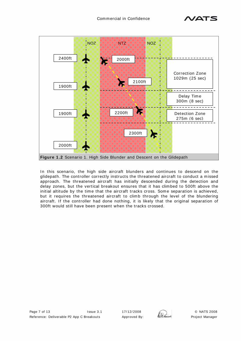
Commercial in Confidence
Page 7 of 13 Issue 3.1 17/12/2008 © NATS 2008
Reference: Deliverable P2 App C Breakouts Approved By: Project Manager
Figure 1.2 Scenario 1. High Side Blunder and Descent on the Glidepath
In this scenario, the high side aircraft blunders and continues to descend on the glidepath. The controller correctly instructs the threatened aircraft to conduct a missed approach. The threatened aircraft has initially descended during the detection and delay zones, but the vertical breakout ensures that it has climbed to 500ft above the initial altitude by the time that the aircraft tracks cross. Some separation is achieved, but it requires the threatened aircraft to climb through the level of the blundering aircraft. If the controller had done nothing, it is likely that the original separation of 300ft would still have been present when the tracks crossed.
NOZ NOZ NTZ
Detection Zone 275m (6 sec)
Delay Time 300m (8 sec)
Correction Zone 1029m (25 sec)
2300ft
2000ft
1900ft
1900ft
2400ft
2200ft
2000ft
2100ft
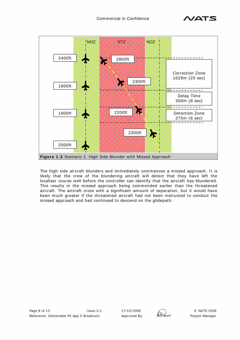
Commercial in Confidence
Page 8 of 13 Issue 3.1 17/12/2008 © NATS 2008
Reference: Deliverable P2 App C Breakouts Approved By: Project Manager
Figure 1.3 Scenario 2. High Side Blunder with Missed Approach
The high side aircraft blunders and immediately commences a missed approach. It is likely that the crew of the blundering aircraft will detect that they have left the localiser course well before the controller can identify that the aircraft has blundered. This results in the missed approach being commended earlier than the threatened aircraft. The aircraft cross with a significant amount of separation, but it would have been much greater if the threatened aircraft had not been instructed to conduct the missed approach and had continued to descend on the glidepath.
NOZ NOZ NTZ
Detection Zone 275m (6 sec)
Delay Time 300m (8 sec)
Correction Zone 1029m (25 sec)
2300ft
2000ft
1900ft
1900ft
2400ft
2200ft
2800ft
2300ft

Commercial in Confidence
Page 9 of 13 Issue 3.1 17/12/2008 © NATS 2008
Reference: Deliverable P2 App C Breakouts Approved By: Project Manager
Figure 1.4 Scenario 3. Low Side Blunder and Descent on the Glidepath
The low side aircraft blunders and continues to descend on the glidepath. The threatened aircraft conducts the missed approach vertical breakout manoeuvre. In excess of the desired 500ft separation is achieved. It should be noted that if no intervention took place, then the original separation of 300ft may well be maintained at the time the tracks cross.
NOZ NOZ NTZ
Detection Zone 275m (6 sec)
Delay Time 300m (8 sec)
Correction Zone 1029m (25 sec)
2000ft
2300ft
2200ft
2200ft
2700ft
1900ft
1700ft
1800ft

Commercial in Confidence
Page 10 of 13 Issue 3.1 17/12/2008 © NATS 2008
Reference: Deliverable P2 App C Breakouts Approved By: Project Manager
Figure 1.5 Scenario 4. Low Side Blunder with Missed Approach
The low side aircraft blunders and immediately commences a missed approach. If the crew of the blundering aircraft detect that they have left the localiser course at an early stage, the missed approach will be commenced earlier than the threatened aircraft. The potential separation is not achieved and the aircraft cross, with any separation only being achieved if the rate of climb of the blundering aircraft is less than the threatened aircraft. This appears to be highly undesirable situation. If the controller had done nothing, the blundering aircraft may well have climbed above the threatened aircraft before the tracks cross.
In summary, a purely vertical breakout manoeuvre does not appear to meet the desired goals, or the spirit of the SOIR manual. In only one of the scenarios is the desired separation met or exceeded. In some cases, the result would have been very little worse if no intervention had taken place at all. A more complex series of interventions is required (e.g. with the controller required to take different actions depending on whether the high or the low side aircraft blunders and whether the blundering aircraft continues to descend or conducts a missed approach). It may be possible to write a safety case based on these very complex rules, and being able to demonstrate that the possibility of a collision is sufficiently remote that it can be ignored. Due to the complex nature of the procedures involved, the vertical breakout manoeuvre is not considered appropriate for Independent Parallel Approaches at HKIA.
1.4 Proposed Breakout Manoeuvre
It has been demonstrated that a SOIR type breakout of the threatened aircraft is not viable. The only remaining possibility is that resolution of the problem could be achieved by turning the blundering aircraft. This is outside the scope of the SOIR manual, which considers that turning the blundering aircraft may not be possible due to a technical problem, or a radio failure. Using a resolution procedure that involves turning the blundering aircraft will need to take these factors into account.
NOZ NOZ NTZ
Detection Zone 275m (6 sec)
Delay Time 300m (8 sec)
Correction Zone 1029m (25 sec)
2000ft
2300ft
2200ft
2200ft
2700ft
1900ft
2500ft
2000ft

Commercial in Confidence
Page 11 of 13 Issue 3.1 17/12/2008 © NATS 2008
Reference: Deliverable P2 App C Breakouts Approved By: Project Manager
The location of the terrain around HKIA means it is highly desirable that a blundering aircraft does not continue to diverge from the final approach track for a long period of time. It is also highly likely that, once a blunder is detected by the crew, that they will commence a missed approach unless technical problems prevent this. The proposed breakout manoeuvre therefore assists the crew in turning back towards the airfield, which is likely to be their preferred course of action.
The proposed breakout manoeuvre can also follow the remaining SOIR principles that the breakout manoeuvre is standard (the blundering aircraft is turned back toward the airfield), and that a horizontal miss distance is achieved.
Figure 1.6 Proposed Breakout Manoeuvre Turning the Blunderer
In the event of a blunder, the controller instructs the blundering aircraft to turn directly towards the airfield. This requires a maximum of a 30 degree turn, so 10 seconds (3 degrees per second) has been allowed for this. A cross track distance of 411m has been allowed, but the actual distance used is likely to be significantly less than this because the radius of turn has not been taken into account. A miss distance has also been included in addition to this contingency allowance.
NOZ NOZ NTZ
Detection Zone 275m (6 sec)
Delay Time (1) 300m (8 sec)
Correction Zone 411m (10 sec)
Miss Distance 60m
Delay Time (2) 300m (8 sec)

Commercial in Confidence
Page 12 of 13 Issue 3.1 17/12/2008 © NATS 2008
Reference: Deliverable P2 App C Breakouts Approved By: Project Manager
Figure 1.7 10 seconds Cross Track Allowance
It should be noted that, as in the case of the SOIR manual example, aircraft are randomly positioned on the two approach tracks and this minimum distance will only be achieved in cases where the aircraft are in the worst case orientation (the blundered slightly ahead of the threatened aircraft). The investigation into the vertical breakout manoeuvre also demonstrates that there will frequently be a significant vertical element to the separation.
The only significant issues remaining are a radio failure by the blundering aircraft, or a technical problem that prevents the blundering aircraft from turning. It is considered that both problems happening at the same time (engine failure or control problem, and a radio failure) can reasonable be ignored.
It is proposed that these two issues are addressed in the same manner with the addition of a second Delay Time allowance into the analysis.
The blundering aircraft has a control problem. The controller issues the turn instruction to the blundering aircraft in Delay Time 1. The pilot replies that he is unable to turn, therefore in Delay Time 2, the controller passes traffic information and, if appropriate, other instructions to the threatened aircraft. Note that in most cases, the degree of lateral and vertical separation may be sufficient.
In the radio failure case, the controller issues the turn instruction to the blundering aircraft in Delay Time 1 but receives no reply. The controller therefore passes traffic information and, if appropriate, other instructions to the threatened aircraft in Delay Time 2.
Note that in both of these situations it is likely that some degree of lateral and vertical separation may also exist, which may be sufficient. If any manoeuvre by the threatened aircraft is undertaken, a further 10 seconds correction time is still available for this to be conducted.
In order to implement such a procedure, a full safety case is required to validate these principles.
Correction Zone 411m (10 sec)
Correction Zone 30 degree
Cross track error
Correction Zone With turn
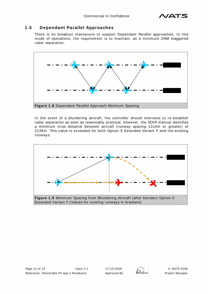
Commercial in Confidence
Page 13 of 13 Issue 3.1 17/12/2008 © NATS 2008
Reference: Deliverable P2 App C Breakouts Approved By: Project Manager
1.5 Dependant Parallel Approaches
There is no breakout manoeuvre to support Dependant Parallel approaches. In this mode of operations, the requirement is to maintain, as a minimum 2NM staggered radar separation.
Figure 1.8 Dependant Parallel Approach Minimum Spacing
In the event of a blundering aircraft, the controller should intervene to re-establish radar separation as soon as reasonably practical, however, the SOIR manual identifies a minimum miss distance between aircraft (runway spacing 1310m or greater) of 2135m. This value is exceeded for both Option S Extended Variant F and the existing runways.
Figure 1.9 Minimum Spacing from Blundering Aircraft (after blunder) Option S Extended Variant F (Values for existing runways in brackets)
Commercial in Confidence
Page 1 of 13 Issue 3.1 17/12/2008 © NATS 2008
Reference: Deliverable P2 App D TAAM Modelling Approved By: Project Manager
AIRSPACE AND RUNWAY CAPACITY STUDY PHASE 1b
Appendix D
TAAM Modelling

Commercial in Confidence
Page 2 of 13 Issue 3.1 17/12/2008 © NATS 2008
Reference: Deliverable P2 App D TAAM Modelling Approved By: Project Manager
CONTENTS
1 TAAM MODELLING OVERVIEW ............................................................................3 1.1 Assumptions ................................................................................................ 3
2 TWO-RUNWAY SCENARIOS ................................................................................3 3 THREE-RUNWAY SCENARIOS .............................................................................4
3.1 Traffic Samples ............................................................................................ 4 3.2 Runway Balance ........................................................................................... 4 3.3 Airborne Crossover Tracks ............................................................................. 7 3.4 List of Three-runway Air Scenarios .................................................................. 9 3.5 Three-Runway Ground Scenarios .................................................................... 9

Commercial in Confidence
Page 3 of 13 Issue 3.1 17/12/2008 © NATS 2008
Reference: Deliverable P2 App D TAAM Modelling Approved By: Project Manager
1 TAAM MODELLING OVERVIEW
Fast time modelling has been employed to provide support to the Phase 1b analysis, building on the TAAM work already completed for Phase 1 and Phase 2. This section describes the process in which the various simulation scenarios have been constructed. The reader is assumed to have some knowledge of the previous simulation work.
The scope of the TAAM work package in Phase 1b includes the following:
• Modelling of Hong Kong International Airport with 2 runways operating in a reorganized PRD airspace;
• Modelling of the 3 third runway options (P/R/SX) from Phase 2 to:
o Investigate the mode of runway operations (Mode 9 versus Mode 23);
o Investigate the mode of arrival operations (Compass versus Terminal);
o Investigate feasibility of airborne crossover tracks for arrivals and departures;
o Investigate some aspects of ground operations in the various modes of operations;
1.1 Assumptions
Various assumptions had to be made before and during the construction of the TAAM simulation scenarios. Major assumptions were agreed in advance with AAHK while other assumptions have been made in consultation with the NATS team to ensure they were appropriate for the situations. The following text includes descriptions of the major assumptions made during the construction of the simulation scenarios.
2 TWO-RUNWAY SCENARIOS
These scenarios aim to simulate a 2-runway Hong Kong International Airport operating in the revised PRD Airspace.
The ILS work has confirmed that independent parallel approaches are not possible with the existing 2 runways. Therefore in the construction of the 2-runway PRD TAAM scenarios, only segregated mode operations were considered. These are airspace only scenarios consistent with previous PRD scenarios. The existing arrangement of arrivals on the north runway and departures from the south runway remains with some freighters also using the south runway for landing.
The traffic sample used was a 68/hr sample created for Phase 1. Originally it was intended to update this TAAM traffic sample with the results of the stand demand study conducted by another consultant for AAHK. However, unlike the LEAPP schedule, the stand demand study did not produce any origin and destination information. Therefore it was not possible to update the TAAM traffic sample.
The TAAM traffic sample also contains traffic for other PRD airports. This allows the interaction amongst the various tracks to different airports to be demonstrated.
In segregated mode, a northern arrival circuit is still available and is joined by the southern arrival circuit at about 15Nm on final. Departures are similar to today except the BEKOL track which has been replaced to connect TD directly with WPT11.
No airborne crossover is required in segregated mode.
Logic for the sequencing of aircraft to airports other than Hong Kong has been preserved from the CAD PRD "baseline" scenarios. Logic for the sequencing of aircraft to Hong Kong has been preserved from the Phase 1 work.

Commercial in Confidence
Page 4 of 13 Issue 3.1 17/12/2008 © NATS 2008
Reference: Deliverable P2 App D TAAM Modelling Approved By: Project Manager
These scenarios are fairly straight forward to construct and are purely created for the visual outputs. No numerical analysis has been performed. The following is a list of modelled 2-runway scenarios which can be found on the CD accompanying this report.
Table 2.1 List of 2-Runway Scenarios
Scenario Option Runway Mode Arr Dep Traffic
0808_PRD_2RWY_NE_SXF_AIR SXF 07 N/A Segregated 68/hr
0808_PRD_2RWY_NW_SXF_AIR SXF 25 N/A Segregated 68/hr
0808_PRD_2RWY_SE_SXF_AIR SXF 07 N/A Segregated 68/hr
0808_PRD_2RWY_SW_SXF_AIR SXF 25 N/A Segregated 68/hr
3 THREE-RUNWAY SCENARIOS
Due to the limit on the size of the TAAM output files, the 3-runway simulation scenarios had to be split into air scenarios and ground scenarios. The air scenarios aimed to model the entire PRD to show the interactions amongst the various tracks for different airports. The scenarios assumed the 3-runway configuration of Option S Extended Variant F running in Mode 23 (A/D/MM) in both terminal and compass arrival modes. Options P and R were not simulated as there is no difference between these and Option S Extended in terms of the airspace apart form the separation between the runways and the finals.
3.1 Traffic Samples
The 2025 LEAPP traffic schedule was used with some minor corrections. Again as in the 2-runway scenarios, it was not possible to update the TAAM traffic sample as the information provided was inadequate. It is important to note that this traffic sample has a peak rate of movement of just over 100, while the average total movement over the 0900L-2100L period is 93. As and when a future update of the LEAPP forecast and busy day schedule happens, it would be advantageous to rerun these scenarios using the most up to date information. This is essential for the accurate assessment of runway and stand demand and to fully assess any ground congestion issues.
The traffic sample used in the air scenarios also contains traffic for Macau, Shenzhen and Zhuhai. This is the same traffic as in the CAD PRD traffic sample.
3.2 Runway Balance
The key aspect to model for all of these scenarios was the runway usage. This involves deciding the preferred runway for takeoffs and landings and setting criteria to opt for another non-preferred runway.
The aim here is to optimise the runway usage by maximizing the number of aircraft being allocated their preferred runways, while minimizing the overall delay incurred. This has been very difficult to achieve.
In compass arrival mode, the preferred landing runway for each arrival route is as follows:
Table 3.1 Preferred Arrival Runway in Compass Mode
North Landing Rwy SNIPE (W) SHRIM (N) SHARK (NE)
South Landing Rwy SHELL/ASTRA (E) OYSTA/BAKER (S) CRABB/HERON (SW)

Commercial in Confidence
Page 5 of 13 Issue 3.1 17/12/2008 © NATS 2008
Reference: Deliverable P2 App D TAAM Modelling Approved By: Project Manager
In terminal arrival mode, the preferred landing runway for each aircraft depends on its carrier, except for all freighters who are mandated to land on the south landing runway. The big assumption here is with the stand/terminal allocation for each of the passenger carriers as this dictates which runway will be each carrier's preferred landing runway. It has been agreed with AAHK prior to building the simulation scenarios that terminal allocation would be done by airline alliance. It's been decided that OneWorld (OW) and affiliated carriers will use the existing facilities (T1) as well as the midfield concourse (MF), Star Alliance (*A) and SkyTeam (ST) carriers will use the new facilities to be built on newly reclaimed land (T3). Most non aligned carriers have been sent to T3 as there are not enough stands for OneWorld at T1/MF. The exact terminal allocation used is as follows:
Table 3.2 Passenger Stand/Terminal Allocation AAL (OW) BAW (OW) CPA (OW) FIN (OW) HDA (OW) JAL (OW)
QFA (OW) T1/Midfield
CCA (*A) GFA JAI JSA JST KAC
AAR (*A) ACA (*A) AIC (*A) ANA (*A) ANZ (*A) COA (*A)
CMI (*A) CSH (*A) DLH (*A) SAA (*A) SAS (*A) SIA (*A)
SWR (*A) THA (*A) THY (*A) UAL (*A)
AFL (ST) AFR (ST) AZA (ST) CAL (ST) CSN (ST) DAL (ST)
KAL (ST) KLM (ST) KQA (ST) MAS (ST) MDA (ST) NWA (ST)
VRG (ST)
CES HVN QTR VIR VGN
ALK ANG BBC BKP CDG CEB
CRK CSC CXA ELY ETH EVA
GIA HKE MAU OEA OHK PAL
PIA PPW RBA RNA SRH SVA
T3
TSO UAE
- Carriers appearing on this list do not necessarily appear in the traffic sample. - Alliance indicated in brackets represent current alliance for each particular carrier. Alliance to which individual carriers are allegiant to may change in the future. - Expected changes in alliance groupings have been taken into account in the stand/terminal allocation based on market intelligence.
These are the preferred stand allocation for each carrier. In the very rare case where all the stands in a particular terminal are occupied, TAAM does not prevent an aircraft from choosing a stand in the alternative terminal. The logic with which the preferred runway is selected is however, based on carrier's preferred terminal, not the actual allocated terminal.
It is recommended that once the future terminal and ground layout has been designed, these simulations are rerun and the terminal allocation finetuned for optimal runway performance and stand occupancy.
Once the preferred runway has been decided, logic has been built into TAAM to check if the preferred runway's arrival queue is longer than a defined threshold. If this is the case, it is the trigger for TAAM to try to assign the non-preferred runway for landing instead. TAAM will also check the length of the arrival queue for the non-preferred runway to make sure it is not being overloaded by the additional traffic.
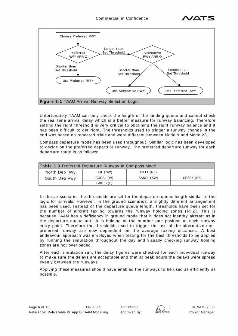
Commercial in Confidence
Page 6 of 13 Issue 3.1 17/12/2008 © NATS 2008
Reference: Deliverable P2 App D TAAM Modelling Approved By: Project Manager
Figure 3.1 TAAM Arrival Runway Selection Logic
Unfortunately TAAM can only check the length of the landing queue and cannot check the real time arrival delay which is a better measure for runway balancing. Therefore setting the right threshold is very critical to obtaining the right runway balance and it has been difficult to get right. The thresholds used to trigger a runway change in the end was based on repeated trials and were different between Mode 9 and Mode 23.
Compass departure mode has been used throughout. Similar logic has been developed to decide on the preferred departure runway. The preferred departure runway for each departure route is as follows:
Table 3.3 Preferred Departure Runway in Compass Mode
North Dep Rwy SHL (NW) HK11 (NE)
CORAL (W) SANDI (SW) CREEK (SE) South Dep Rwy LAKES (E)
In the air scenario, the thresholds are set for the departure queue length similar to the logic for arrivals. However, in the ground scenarios, a slightly different arrangement has been used. Instead of the departure queue length, thresholds have been set for the number of aircraft taxiing towards the runway holding zones (RHZ). This is because TAAM has a deficiency in ground mode that it does not identify aircraft as in the departure queue until it is holding at the number one position at each runway entry point. Therefore the thresholds used to trigger the use of the alternative non-preferred runway are now dependent on the average taxiing distances. A best endeavour approach was employed when testing for the best thresholds to be applied by running the simulation throughout the day and visually checking runway holding zones are not overloaded.
After each simulation run, the delay figures were checked for each individual runway to make sure the delays are acceptable and that at peak hours the delays were spread evenly between the runways.
Applying these measures should have enabled the runways to be used as efficiently as possible.
Choose Preferred RWY
Preferred RWY ARR Q
Use Preferred RWY
Shorter than Set Threshold
Alternative RWY ARR Q
Longer than Set Threshold
Use Preferred RWY Use Alternative RWY
Shorter than Set Threshold
Longer than Set Threshold

Commercial in Confidence
Page 7 of 13 Issue 3.1 17/12/2008 © NATS 2008
Reference: Deliverable P2 App D TAAM Modelling Approved By: Project Manager
3.3 Airborne Crossover Tracks
Airborne crossover tracks or stack swapping tracks have been designed to bring aircraft arriving on routes from the North and West to land on the south runway and similarly for aircraft arriving on routes from the South and East to land on the north runway. These are essential when the airport is running in terminal arrival mode or when runway balancing is required in compass arrival mode. Figures 3.2 and 3.3 show the suggested arrival airborne crossover tracks and their crossover altitudes.
Airborne crossover tracks are also essential when offloading excess departures from one runway to the another in compass departure mode, i.e. departing off the north runway for destinations in the south and vice versa. Figures 3.4 and 3.5 show the suggested departure crossover tracks and their crossover altitudes. The exception is departures off the north runway towards CORAL and SANDI where the excessive track mileage incurred makes them impractical. Runway balancing should be achievable with departure traffic for LAKES and CREEK.
Figure 3.2 Suggested Airborne Crossover Tracks – Easterly Arrivals
Figure 3.3 Suggested Airborne Crossover Tracks – Westerly Arrivals
150
140
170 180 190
190
150
140
190
170
180 190

Commercial in Confidence
Page 8 of 13 Issue 3.1 17/12/2008 © NATS 2008
Reference: Deliverable P2 App D TAAM Modelling Approved By: Project Manager
Figure 3.4 Airborne Crossover Tracks – Easterly Departures
Figure 3.5 Airborne Crossover Tracks – Westerly Departures
150
140
170
180
190
190
160
150
150
140
170 180
190
190 90
100
Commercial in Confidence
Page 9 of 13 Issue 3.1 17/12/2008 © NATS 2008
Reference: Deliverable P2 App D TAAM Modelling Approved By: Project Manager
3.4 List of Three-runway Air Scenarios
The air scenarios have been constructed for the visual outputs. No numerical analysis has been performed. The following is a list of modelled 3-runway air scenarios which can be found on the CD accompanying this report.
Table 3.4 List of 3-Runway Air Scenarios
Scenario Option Runway Mode Arr Dep Traffic 0808_PRD_NE_SXF_AIR_CC SXF 07 23 Compass Compass 2025
0808_PRD_NW_SXF_AIR_CC SXF 25 23 Compass Compass 2025
0808_PRD_SE_SXF_AIR_CC SXF 07 23 Compass Compass 2025
0808_PRD_SW_SXF_AIR_CC SXF 25 23 Compass Compass 2025
0808_PRD_NE_SXF_AIR_TC SXF 07 23 Terminal Compass 2025
0808_PRD_NW_SXF_AIR_TC SXF 25 23 Terminal Compass 2025
0808_PRD_SE_SXF_AIR_TC SXF 07 23 Terminal Compass 2025
0808_PRD_SW_SXF_AIR_TC SXF 25 23 Terminal Compass 2025
3.5 Three-Runway Ground Scenarios
Each of the 3 three-runway options from Phase 2 have been modelled in terms of ground operations. The aim of the simulations is to investigate any potential ground issues as a result of running the airport in the various modes of operations with a particular focus in runway crossings and congestion along the section of Taxiways A and B north of the current passenger terminal building.
Altogether 20 three-runway ground scenarios have been constructed representing each of the permutations possible for the 3 options, 2 runway directions, 2 modes of operations and 2 arrival runway modes.
3.5.1 Ground Layout Development
The runway location for each of the 3 options was defined in Phase 2 but no definite ground layout was designed. A ground layout for each of the 3 options had to be developed for Phase 1b to enable the simulations to run. Minimal efforts have been spent to design an optimal layout as this is not one of the main objectives of the study and TAAM only requires a layout, any layout, to run. The layouts were produced with a common sense approach based on experience of what would be required and what should be workable. These designs have not been properly evaluated and must not be considered as recommendations by NATS.
ICAO guidance in terms of sizing and separation between taxiways and stands have been applied but have not been verified. There are inadequacies and deficiencies such as the location of RETs and runway crossing points. While these would not be operationally acceptable, these deficiencies do not affect the running of the simulation or the post-sim analysis.
The number of stands for the new terminal (T3) has deliberately been maximised so that there is a significant number of spare stands for each of the 3 options. TAAM "terminates" an aircraft if the aprons are full, which means the aircraft is purged from the simulation. Terminations affect the accuracy of the results and by putting in more stands than required this situation can be minimized.
The midfield area has been inherited from Phase 1, where this design was one of those supplied by AAHK.

Commercial in Confidence
Page 10 of 13 Issue 3.1 17/12/2008 © NATS 2008
Reference: Deliverable P2 App D TAAM Modelling Approved By: Project Manager
For the centre runway in all options, the RETs have been deleted for visual clarity. In reality they are expected to be kept with new RETs built to exit to the north side of the runway in the event one of the other runways are shut for any reason.
Figures 3.6, 3.7 and 3.8 show the 3 layouts as they appear in ReView.
Figure 3.6 Option P Ground Layout in TAAM/ReView
Figure 3.7 Option R Ground Layout in TAAM/ReView

Commercial in Confidence
Page 11 of 13 Issue 3.1 17/12/2008 © NATS 2008
Reference: Deliverable P2 App D TAAM Modelling Approved By: Project Manager
Figure 3.8 Option S Extended Variant F Ground Layout in TAAM/ReView
3.5.2 Scenario Development
The gate allocation logic has been kept the same across each of the 3 options for all 20 scenarios as described above in Section 3.2.
The taxiing logic is based on standard routing developed together with the ATCO experts. There are some major rule applications:
• No tows are allowed across any runway;
• No tows are allowed to the maintenance area except for Cathay Pacific and Dragonair;
• The midfield area has taxilanes either side of the toast rack satellites. Through traffic is discouraged but not prevented from using these taxilanes;
• Taxiway V is primarily used for northbound traffic, W for southbound;
• For Option P, each aircraft taxiing around the end of Runway 25C counts as a runway crossing;
• For Option S Extended, Stands E19, N68 and N70 are closed;
• For north runway arrivals in Option S Extended:
o In 07, T1 arrivals cross at V/W, midfield arrivals cross at the western crossing, T3 arrivals follow the (outer) centre taxiway between Runway 07L and Runway 07C and do not cross Runway 07C;
o In 25, only midfield arrivals are allowed to cross Runway 25C, T1 arrivals taxi to gate via Link A11;
3.5.3 List of Three-runway Ground Scenarios
The following is a list of modelled 3-runway ground scenarios which can be found on the CD accompanying this report.

Commercial in Confidence
Page 12 of 13 Issue 3.1 17/12/2008 © NATS 2008
Reference: Deliverable P2 App D TAAM Modelling Approved By: Project Manager
Table 3.5 List of 3-Runway Ground Scenarios
Scenario Option Runway Mode Arr Dep Traffic 0808_P1B_07_P_GROUND_M09_CC P 07 9 Compass Compass 2025
0808_P1B_07_P_GROUND_M09_TC P 07 9 Terminal Compass 2025
0808_P1B_07_P_GROUND_M23_CC P 07 23 Compass Compass 2025
0808_P1B_07_P_GROUND_M23_TC P 07 23 Terminal Compass 2025
0808_P1B_25_P_GROUND_M09_CC P 25 9 Compass Compass 2025
0808_P1B_25_P_GROUND_M09_TC P 25 9 Terminal Compass 2025
0808_P1B_25_P_GROUND_M23_CC P 25 23 Compass Compass 2025
0808_P1B_25_P_GROUND_M23_TC P 25 23 Terminal Compass 2025
0808_P1B_07_R_GROUND_M09_CC R 07 9 Compass Compass 2025
0808_P1B_07_R_GROUND_M09_TC R 07 9 Terminal Compass 2025
0808_P1B_07_R_GROUND_M23_CC R 07 23 Compass Compass 2025
0808_P1B_07_R_GROUND_M23_TC R 07 23 Terminal Compass 2025
0808_P1B_25_R_GROUND_M09_CC R 25 9 Compass Compass 2025
0808_P1B_25_R_GROUND_M09_TC R 25 9 Terminal Compass 2025
0808_P1B_25_R_GROUND_M23_CC R 25 23 Compass Compass 2025
0808_P1B_25_R_GROUND_M23_TC R 25 23 Terminal Compass 2025
0808_P1B_07_SXF_GROUND_M23_CC SXF 25 23 Compass Compass 2025
0808_P1B_07_SXF_GROUND_M23_TC SXF 25 23 Terminal Compass 2025
0808_P1B_25_SXF_GROUND_M23_CC SXF 25 23 Compass Compass 2025
0808_P1B_25_SXF_GROUND_M23_TC SXF 25 23 Terminal Compass 2025
3.5.4 Ground Scenario Outputs & Numerical Analysis
NATS' standard analysis suite was run using outputs from each of the 20 simulation scenarios. Of the 50 analysis metrics, a number of these are of use to the ATCO experts when performing their own analyses:
• Average arrival taxi times undelayed/delayed;
• Average departure taxi times undelayed/delayed;
• Average runway holding zone (RHZ) delay for departures;
• Number of runway crossings;
• Crossfield taxiway usage;
• T3 link taxiway usage for Option S Extended;
• Delay incurred on Taxiways A/B for Option S Extended;
These numbers have been deduced and summed in various ways (by apron, by hour, by runway, by taxiway etc).
Copies of the summarised results can be found on the CD accompanying this report.
Recommendations:
R11: It is recommended that the LEAPP/AirBiz traffic forecasts and busy day schedules be updated again:
• to include original/destination information to allow accurate assessment of stand and runway demand and the mode of runway operations (terminal vs compass mode);
• to include a 2030 scenario;

Commercial in Confidence
Page 13 of 13 Issue 3.1 17/12/2008 © NATS 2008
Reference: Deliverable P2 App D TAAM Modelling Approved By: Project Manager
R12: Develop a stand/terminal utilization plan taking into account availability of future development including the midfield area and the new terminal, preferably in conjunction with airline users;
R13: Rerun these simulation scenarios once:
• A proper ground layout has been designed;
• The traffic forecasts and busy day schedules have been updated;
• A stand/terminal utilization plan for the future has been developed;
in order to reassess more accurately the ground operations based on the most up-to-date information.