cover fast 11/03/98 21:55 page 1 - · pdf file03-11-1998 · for a300/a300-600/a310...
TRANSCRIPT

Cover FAST 11/03/98 21:55 Page 1

© AIRBUS INDUSTRIE 1998
Publisher: Airbus Industrie Customer Services, 1 rond-point Maurice Bellonte, 31707 Blagnac Cedex, FranceEditor: Denis Dempster, Product MarketingTelephone +33 (0)5 61 93 39 29, Telex AIRBU 530526F, Telefax +33 (0)5 61 93 27 67 Graphic design: Agnès Lacombe, Customer Services Marketing Photo-engraving: Passion Graphic, 60 boulevard Déodat de Séverac, 31027 Toulouse Cedex, FrancePrinter: Escourbiac, 5 avenue Marcel Dassault, 31502 Toulouse Cedex, France
This issue of FAST has been printed on paper produced without using chlorine, to reduce waste and help to conserve natural resources. 'Every little helps'.
FAST may be read on Internet http://www.airbus.com
The articles herein may be reprinted without permission except where copyright source is indicated, but with acknowledgement to Airbus Industrie. Articles which may be subject to ongoing review must have their accuracy verified prior to reprint. The statements made herein do not constitute an offer. They are based on the assumptions shown and are expressed in good faith. Where the supporting grounds for these statements are not shown, the Company will be pleased to explain the basis thereof.
AIRBUSTECHNICALDIGEST
NUMBER 22MARCH 1998
HYDRAULIC SYSTEMPREVENTING LEAKSJEROME QUENESCOURT
22
THE PORTABLE WATER DETECTION TOOLFOR A300/A300-600/A310 AIRCRAFTRENE SAVOIE AND MARIE-SOPHIE CALAIS
1717IMPLEMENTING JAR-OPS WITHAIRBUS INDUSTRIE OPERATIONAL DOCUMENTATIONGUY DI SANTO
2121
THE INTERNATIONAL REGULATORY CLIMATEANDREW S. Mc CLYMONT 1111
7FUEL SYSTEMDETECTING LEAKS USING HELIUMALAIN MARECHAL AND ALAIN DENINOTTI
7
25LIGHTNING STRIKES AND AIRBUS FLY-BY-WIRE AIRCRAFTCAPTAIN CHRIS KRAHE 25
28AIM-FANS WINS GROWING NUMBER OF ORDERSJEAN-PIERRE DAMBRINE 28
30CUSTOMER SERVICES CONFERENCES 30THE FIRST AVIATION REGULATION? 3131RESIDENT CUSTOMER SUPPORTREPRESENTATION 3232
FAST / NUMBER 22 1
FAST 22/p1 � p6 11/03/98 23:45 Page 1

FAST / NUMBER 22 3FAST / NUMBER 222
Jérome QuenescourtHydraulic Systems Engineer
Eng. & Technical SupportAirbus Industrie
Customer Services Directorate
In an earlierarticle
"Hydraulic system- Working
practices" (FASTN°13), somefundamental
working practiceswere detailed,
aimed to reducethe number of
leaks. Since then,a dedicatedmonitoring
programme hasbeen launched and
working groupsformed to further
minimise theoccurrence
of leaks. The purpose ofthis article is to
provide guidelinesfor maintenance
personnel toreduce the
frequency of leakseven further.
HYDRAULIC SYSTEMPreventing leaks
Thereare three as-pects to bec o n s i d e r e d
when looking for the causes of leaks:● design, ● control of quality in production,● maintenance.
Only the manufacturer can do some-thing about the first two itemsandAirbus Industrie is continuallystudying how repetitive defects can bedesigned out of the system either bychanging the design, the supplier and/or the production process (Figure 1).
DESIGN
Part of the designer’s work is to makethe maintenance interventions, sched-uled and unscheduled, as infrequent aspossible, and the maintenance practicesas simple as possible. The TechnicalDesign Directives for the hydraulic sys-tem, written originally for the A300, arelargely still applicable, however therehave been some changes such as thegreater use of titanium piping which islighter than stainless steel and lessprone to pin-hole corrosion; the gener-alised use of flareless fittings; installa-tion of built-in Hydraulic SystemMonitoring Units and the qualificationof new fluids and methods of repairingpipes.
Further work is being done to en-hance the built-in test and monitoringcapabilities of the system allowing eas-ier and more accurate maintenance in-terventions as early as possible in thedegradation sequence.
QUALITY IN PRODUCTION
Computer aided design and manufac-turing of pipes have greatly improvedthe quality of the installation of piperuns particularly in areas having manypipes with multiple bends in closeproximity. The improved installationallied with:● respect of torque values and propertightening methods,● stress free installation,● seal installation with lubricants● use of dedicated tools,all lead to trouble free installations.
The Airbus Industrie ProcessSpecification (AIPS) sets the standardsfor production and installation of thehydraulic systems for all the Airbusaircraft.
One area where manufacturer andoperator have to be particularly vigilantis in the inadvertent acquisition of "bo-gus" parts that do not always conformwith basic quality standards. Hydraulicsystems have been known to sufferfrom the installation of these parts, par-
ticularly seals, which has led to rein-forced audits at vendors and informa-tion being transmitted to the operatorsthrough the Service Information Letter(SIL 29-064).
MAINTENANCE
Maintenance can be divided into twogroups - preventive and corrective.
Preventive maintenance
In the Maintenance Planning Docu-ments (MPD) there are scheduled taskswhich are defined to ensure hydraulicsystem integrity and avoid leaks. Thesetasks are found in the Zonal InspectionProgramme under System checks (typi-cal defects are shown in Figures 2 to 6).
Zonal inspection programme
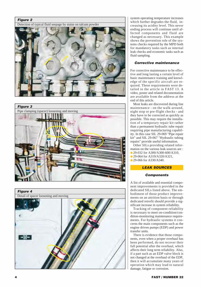
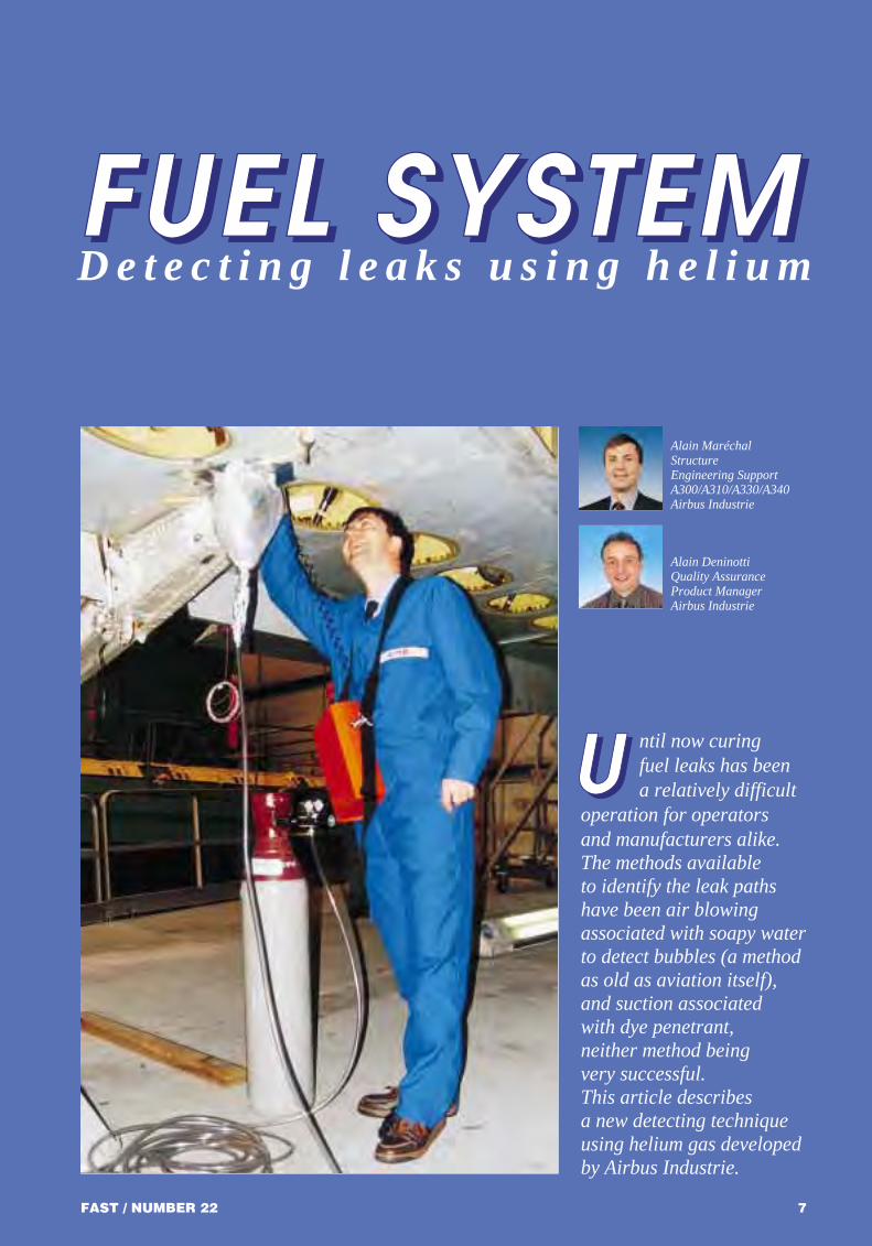
The zonal programme asks for visualinspection of various aircraft systemsincluding the hydraulic system, at vari-ous locations (wheel well bay, underfloor, engine pylons, wing trailing edgeetc). It is during the visual inspectionsthat anomalies can be identified andcorrected, such as:● presence of seepage (Figure 2)● loose or missing ties, spacers orclamp blocks, (Figures 3, 4, 6)● damaged pipe-lines● loose connections● line chafing (Figure 6 and 7).
System checks
Some system checks are fundamentalto ensure the system integrity and toprevent future damage. For instance,regular hydraulic fluid sampling to al-low the operator to maintain the fluidquality within given limits (aciditylevel, chlorine and water content) andtherefore avoid component erosion orcorrosion. Moreover, as soon as com-ponents become eroded, internal leak-age rates increase, fluid is laminated,
Figure 1Hydraulic Leak Monitoring
*ARCS*ARCS: Airbus Representative
Communication System
Codingevents
Resident CustomerRepresentative Office
• StudyAirline/fleet
• Trackingrepeaters
• Effectivenessof improvement(SB)
Airbus Data Base (FORDSREP)
Analysis
Information flow: about 2000 events in 1997 (all A/C types)
TECH LOG
Extraction
Leakevents
New leakevents
LeakDataBase
FAST 22/p1 � p6 11/03/98 23:48 Page 2

FAST / NUMBER 22 3FAST / NUMBER 222
Jérome QuenescourtHydraulic Systems Engineer
Eng. & Technical SupportAirbus Industrie
Customer Services Directorate
In an earlierarticle
"Hydraulic system- Working
practices" (FASTN°13), somefundamental
working practiceswere detailed,
aimed to reducethe number of
leaks. Since then,a dedicatedmonitoring
programme hasbeen launched and
working groupsformed to further
minimise theoccurrence
of leaks. The purpose ofthis article is to
provide guidelinesfor maintenance
personnel toreduce the
frequency of leakseven further.
HYDRAULIC SYSTEMPreventing leaks
Thereare three as-pects to bec o n s i d e r e d
when looking for the causes of leaks:● design, ● control of quality in production,● maintenance.
Only the manufacturer can do some-thing about the first two itemsandAirbus Industrie is continuallystudying how repetitive defects can bedesigned out of the system either bychanging the design, the supplier and/or the production process (Figure 1).
DESIGN
Part of the designer’s work is to makethe maintenance interventions, sched-uled and unscheduled, as infrequent aspossible, and the maintenance practicesas simple as possible. The TechnicalDesign Directives for the hydraulic sys-tem, written originally for the A300, arelargely still applicable, however therehave been some changes such as thegreater use of titanium piping which islighter than stainless steel and lessprone to pin-hole corrosion; the gener-alised use of flareless fittings; installa-tion of built-in Hydraulic SystemMonitoring Units and the qualificationof new fluids and methods of repairingpipes.
Further work is being done to en-hance the built-in test and monitoringcapabilities of the system allowing eas-ier and more accurate maintenance in-terventions as early as possible in thedegradation sequence.
QUALITY IN PRODUCTION
Computer aided design and manufac-turing of pipes have greatly improvedthe quality of the installation of piperuns particularly in areas having manypipes with multiple bends in closeproximity. The improved installationallied with:● respect of torque values and propertightening methods,● stress free installation,● seal installation with lubricants● use of dedicated tools,all lead to trouble free installations.
The Airbus Industrie ProcessSpecification (AIPS) sets the standardsfor production and installation of thehydraulic systems for all the Airbusaircraft.
One area where manufacturer andoperator have to be particularly vigilantis in the inadvertent acquisition of "bo-gus" parts that do not always conformwith basic quality standards. Hydraulicsystems have been known to sufferfrom the installation of these parts, par-
ticularly seals, which has led to rein-forced audits at vendors and informa-tion being transmitted to the operatorsthrough the Service Information Letter(SIL 29-064).
MAINTENANCE
Maintenance can be divided into twogroups - preventive and corrective.
Preventive maintenance
In the Maintenance Planning Docu-ments (MPD) there are scheduled taskswhich are defined to ensure hydraulicsystem integrity and avoid leaks. Thesetasks are found in the Zonal InspectionProgramme under System checks (typi-cal defects are shown in Figures 2 to 6).
Zonal inspection programme
The zonal programme asks for visualinspection of various aircraft systemsincluding the hydraulic system, at vari-ous locations (wheel well bay, underfloor, engine pylons, wing trailing edgeetc). It is during the visual inspectionsthat anomalies can be identified andcorrected, such as:● presence of seepage (Figure 2)● loose or missing ties, spacers orclamp blocks, (Figures 3, 4, 6)● damaged pipe-lines● loose connections● line chafing (Figure 6 and 7).
System checks
Some system checks are fundamentalto ensure the system integrity and toprevent future damage. For instance,regular hydraulic fluid sampling to al-low the operator to maintain the fluidquality within given limits (aciditylevel, chlorine and water content) andtherefore avoid component erosion orcorrosion. Moreover, as soon as com-ponents become eroded, internal leak-age rates increase, fluid is laminated,
Figure 1Hydraulic Leak Monitoring
*ARCS*ARCS: Airbus Representative
Communication System
Codingevents
Resident CustomerRepresentative Office
• StudyAirline/fleet
• Trackingrepeaters
• Effectivenessof improvement(SB)
Airbus Data Base (FORDSREP)
Analysis
Information flow: about 2000 events in 1997 (all A/C types)
TECH LOG
Extraction
Leakevents
New leakevents
LeakDataBase
FAST 22/p1 � p6 11/03/98 23:48 Page 2
This is an example of why trackingof component reliability may justify aneed for a fixed time between overhaul(TBO), replacement of a part, or em-bodiment of a modification.
Seals
The keys issues for seal reliability areproduct manufacturing quality andproper installation.
Manufacturing quality
The product manufacturing quality hasbeen recently at the focal point of in-service failures on the A330/A340 pro-grams. (Refer to SIL 29-064). As a re-sult, two vendors have been removedfrom the approved list of suppliers be-cause of identified quality deficiencyon some of their products. Three othervendors (Le Joint Francais, DowtyU.K, and Parker) have been auditedand their standard of manufacturingquality judged satisfactory.
Installation
Chapter 20 of the Aircraft MaintenanceManual recommends use of certaintools and provides other advice forproper installation of seals.
In the previous article in FAST itwas stated that "Seals, O-rings andpacking washers should be smearedwith MCS-352 lubricant or hydraulicfluid". It has recently been discoveredthat the application of MCS-352 on thethreads of plug-in unions can have anegative effect, causing the seal to besqueezed and damaged (Figure 5).
For plug-in unions hydraulic fluidshould be used as a lubricant.
Pipes
There are generally three origins ofpipe failure:● chafing,● installation under stress,● corrosion.
High quality of manufacture of thepipes allowing good installation canlargely prevent these types of failures.A recent audit performed on all Airbuspipe production centres revealed thatmanufacturing processes and tech-niques are well adapted and controlled,with the use of :● numerical controlled bending ma-chines and improved knowledge ofspring back effect, ● laser dimensional check for every in-dividual manufactured pipe,● chlorine free pipe cleaning,● laser marking.
Compliance with installation ruleswill avoid chafing and pre-stressed installations. Design will also help
FAST / NUMBER 22 5
Plug-in union
O-Ring
Lubricant on the threads
Manifold port
Pinching
At final tighteningthe seal is pinched
between the plug-in union and the edge of
the chamfer. Thispinching damages the
rubber on the outer surface of the seal
During tightening of the union the lubricant
fills the groove and pushes the seal out
FAST / NUMBER 224
system operating temperature increaseswhich further degrades the fluid, in-creasing its acidity level. This neverending process will continue until af-fected components and fluid arechanged as necessary. This exampleshows the prevention role of the sys-tems checks required by the MPD bothfor mandatory tasks such as internalleak checks and economic tasks such asfluid sampling.
Corrective maintenance
For corrective maintenance to be effec-tive and long lasting a certain level ofbasic maintenance training and knowl-edge of the specific aircraft are re-quired. These requirements were de-tailed in the article in FAST 13. Avideo, poster and related documentationare available from the address at theend of this article.
Most leaks are discovered during linemaintenance - on the walk-around,night stop or pre-flight checks - andthey have to be corrected as quickly aspossible. This may require the installa-tion of a temporary repair kit ratherthan a permanent hydraulic tube repairrequiring pipe manufacturing capabil-ity. In this case SIL 29-069 "Pipe repairkit" and SIL 29-067 "Hydraulic tubingrepairs" provide useful information.
Other SILs providing related infor-mation on the various leak sources are :● 29-032 for A300/A300-600/A310,● 29-064 for A319/A320/A321,● 29-066 for A330/A340.
LEAK SOURCES
Components
A list of available and essential compo-nent improvements is provided in thededicated SILs listed above. The em-bodiment of those product improve-ments on an attrition basis or throughdedicated retrofit should provide a sig-nificant increase in system reliability.
Tracking of component reliability is necessary to meet on-condition/con-dition-monitoring maintenance require-ments. For hydraulic systems it con-cerns the main components such as theengine driven pumps (EDP) and powertransfer units.
There is evidence that those compo-nents, even when a proper overhaul hasbeen performed, do not recover theirfull potential after the overhaul, whichaffects their long term reliability. Also,if a part such as an EDP valve block isnot changed at the overhaul of the EDP,then it will accumulate many years ofoperation which may lead to naturaldamage, fatigue or corrosion.
Figure 2Detection of typical fluid seepage by stains on talcum powder
Figure 3Pipe clamping (spacer) loosening and moving
Figure 4Detail of spacer loosening and moving
Figure 6Risk of chafing due to loose clamping
Figure 5Effect of lubricant on plug-in union threads
FAST 22/p1 � p6 11/03/98 23:50 Page 4

with improved clamping definition (adjustable brackets) and dampening ofpressure pulsation of pumps.
Ageing affects the integrity of pipeinstallations (Figures 3 to 7) justifyingthe importance of periodic inspectionchecks such as in the zonal inspection.Typical ageing effects are:● reduced efficiency of clamp blocks
due to loosening, wear or damage, ● corrosion development (exposure tocontaminants such as saline atmos-phere, spillage from toilets),● damage to pipe surfaces duringmaintenance.
Pipe fittings
Maintenance is a common source ofleakage when loosening is due to un-der-tightening (often found on large fit-tings) and damage is due to over-tight-ening, generally found on aluminiumfittings or small fittings and due tocracking from frequent loosening andtightening. The main development infitting technology has been the intro-duction of more reliable flarelessunions. However experience has shownthat there is no substitute for systematiccompliance with correct tightening pro-cedures and use of the correct tools.
Airbus Industrie is studying more"damage tolerant" fitting designs suchas Rosan (Figure 8) and alternativetightening techniques which can copewith vibration and a maintenance envi-ronment where use of torque wrenchesis not common practice.
FAST / NUMBER 226
Adapter
O-Ring
Serrations
Lockring
CONCLUSION
Lubricant MCS-352 should not be used on the threads of the plug-in unions. Although the hydraulic leak rate on a fleet-widebasis is approaching a satisfactory level it can and will be improved. Further efforts by Airbus Industrie and the vendors toimprove hydraulic system reliability together with preventive maintenance actions applied by operators when necessary andproper application of procedures, will keep the hydraulic leak rates within an acceptable level. For this purpose, customers’feedback on in-service experience is vital.
Airbus Industrie will assist any operator suffering from a perceived excessive leak rate to initiate a leak preventive pro-gramme. This programme has been successfully implemented by a number of operators one of whom experienced a reduc-tion in leak rates by 50%. ■
Figure 8Rosan fitting definition: union and port
Figure 7Risk of chafing due to small clearance
For further information please contact: AIRBUS INDUSTRIE Engineering Services, Engineer Hydraulic Systems, Mr TORBJÖRN KETTEL
FAST / NUMBER 22 7
Alain MaréchalStructure Engineering SupportA300/A310/A330/A340Airbus Industrie
Alain DeninottiQuality Assurance Product ManagerAirbus Industrie
ntil now curingfuel leaks has been a relatively difficult
operation for operators and manufacturers alike. The methods available to identify the leak pathshave been air blowingassociated with soapy waterto detect bubbles (a methodas old as aviation itself),and suction associated with dye penetrant, neither method being very successful. This article describes a new detecting techniqueusing helium gas developedby Airbus Industrie.
FFFFUUUUEEEELLLL SSSSYYYYSSSSTTTTEEEEMMMMD e t e c t i n g l e a k s u s i n g h e l i u m
UUUU
FAST 22/p1 � p6 11/03/98 23:53 Page 6

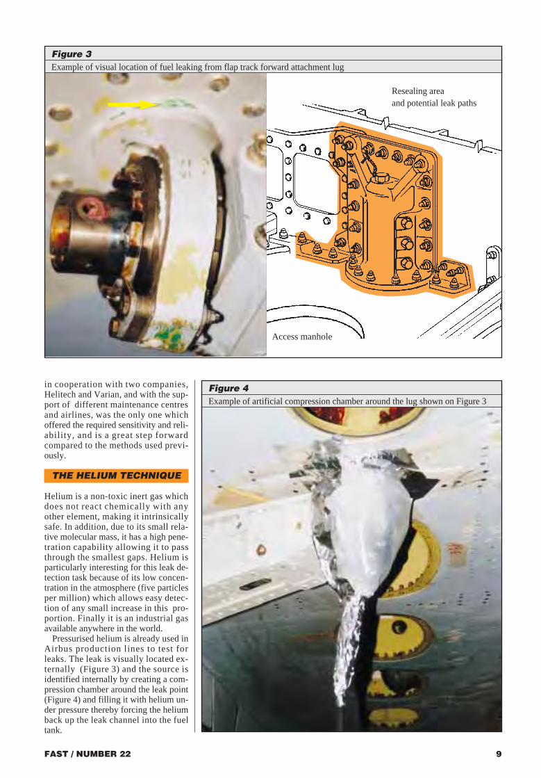
FAST / NUMBER 22 9FAST / NUMBER 228
Fuel tanks in modern commercial air-liners are housed principally in thewings, and the wing structure is also thefuel tank structure; there are no rubbertanks or other forms of inner wallswithin the wings. Wing structures arecomposed of large skin panels, dozensof ribs and stringers, and thousands ofbolts and rivets covered with a sealantto prevent fuel seepage (Figure 1). Thisstructure is flexible, as anyone who hasflown in turbulent weather will havenoticed, as they watch the wing tipsmoving up and down. Eventually fuelseepage does occur and the leaks be-come evident on the outer surface ofthe skin. The visible point of seepage is
at the end of the leak path (Figure 2a)and an efficient repair requires that theorigin of the leak path (or paths) isidentified and properly sealed. If not,there is a high risk that the leak will ap-pear again, and quite often it does.
THE INNOVATIVEAPPROACH
Airbus Industrie investigated severalleak path detection methods and has se-lected and developed a new detectiontechnique using helium as a tracer gasto allow easier detection of the sourceof the leak (Figure 2b).
This technique, which was developed
INSIDE
OUTSIDE
Helium
Gas leak=
Location ofsealant
deterioration
INSIDE
OUTSIDE
Leakingarea
Figure 2Different phases of detection method
Figure 4Example of artificial compression chamber around the lug shown on Figure 3
Figure 1Wing structure (typical)
in cooperation with two companies,Helitech and Varian, and with the sup-port of different maintenance centresand airlines, was the only one whichoffered the required sensitivity and reli-ability, and is a great step forwardcompared to the methods used previ-ously.
THE HELIUM TECHNIQUE
Helium is a non-toxic inert gas whichdoes not react chemically with anyother element, making it intrinsicallysafe. In addition, due to its small rela-tive molecular mass, it has a high pene-tration capability allowing it to passthrough the smallest gaps. Helium isparticularly interesting for this leak de-tection task because of its low concen-tration in the atmosphere (five particlesper million) which allows easy detec-tion of any small increase in this pro-portion. Finally it is an industrial gasavailable anywhere in the world.
Pressurised helium is already used inAirbus production lines to test forleaks. The leak is visually located ex-ternally (Figure 3) and the source isidentified internally by creating a com-pression chamber around the leak point(Figure 4) and filling it with helium un-der pressure thereby forcing the heliumback up the leak channel into the fueltank.
2a Identification of a leak 2b Use of helium gas as tracer gas
Figure 3Example of visual location of fuel leaking from flap track forward attachment lug
Resealing areaand potential leak paths
Access manhole
FAST22 p7 � 10 11/03/98 23:36 Page 8

FAST / NUMBER 2210
The procedure must start with a clearmapping of the fuel leak on the outersurface of the tank (precise leak loca-tion and approximate leak rate) thenthe tank can be defuelled, drained andvented until it becomes completely dry.Before entering the tank, all the safetychecks have to be performed to ensureadequate ventilation and acceptablefuel vapour concentration.
An artificial compression chamber(Figure 5a) over the leaking area has tobe created. This is simply done by pen-etrating one corner of a plastic bagwith the rubber hose from the heliumsupply and sealing the join with sealantand aluminium tape. The open end ofthe plastic bag is attached to the skin ofthe wing around the leak, also by alu-minium tape. This simple method canbe easily adapted to awkward situa-tions as shown on page 7 where theleak is from a flap track attachment fit-ting. This artificial chamber must beable to withstand a maximum internalpressure of 200 mbar. When this hasbeen done, the helium injection canstart at a constant pressure.The initialpressure choice depends on the kind ofleak (rate, location) and must be basedon knowledge of the structure and po-tential leak paths. Then the jet of he-lium being forced into the tank has tobe found. By moving the detection"sniffer" (Figure 5b) probe inside thetank, there will be various sound fre-quencies emitted by the detection de-vice depending on how far the probe isfrom the jet of helium (and the originof the leakage). During this operation,it could be necessary to increase the in-jection pressure. It should not be for-gotten that more than one leak may ex-ist in the same area. Therefore it couldbe necessary to repeat this operationseveral times. In this case it is recom-mended to vent the area between twodetection operations.
The artificial compression chambershould not be removed, because whenthe repair has been performed it can beused to check, in the same way, the qual-ity of the repair. This will prevent re-fuelling and de-fuelling of the tank if thequality of the repair is not acceptable.
CONCLUSION
Conventional methods for detecting fuel leaks are now becoming obsolete. This helium technique has been tested and finetuned on several aircraft. It is now the most efficient and reliable method of identifying fuel leak sources. It is cost effectiveas a much lower number of manhours are required to cure fuel leaks and it reduces significantly the aircraft downtime. Inaddition it also confirms the integrity of the repair, avoiding the use of fuel. This operation alone can easily save four daysof ground time.
Airbus Industrie highly recommends that operators apply this procedure, which is described in SIL. 57-091 applicable toall Airbus aircraft types. ■
Skin
INSIDE
OUTSIDE
Rib
Fuel tank
Helium injectedinto the chamber
Artificial compressionchamber taped overexternal leaking point
Skin
Rib
Fuel tank
Leak source detected by helium detector nozzle "sniffer"
INSIDE
OUTSIDE
5b Detection
Figure 5Detection phases5a Injection
nternational cooperation on civil aircraft regulations and certification has been in existence to some extent, initially a small extent, for more than 50 years.
It has been increasing in recent years as Europe slowly draws together many diversenational bodies to create a single Joint Aviation Authority to act on behalf of eachEuropean country member. At the same time, the level of cooperation on both sides of theAtlantic and with other regions of the world is also increasing in a manner which should -in the long term - achieve a practical worldwide certification process and an improvedoverall safety regulation system.That ideal is some way ahead, but is becoming a possibility for aircraft airworthinesscertification, if political restraints and perceived sovereignty protection policies can beavoided. It may take longer for operational "control" to reach such a common goal. We need to persuade the politicians to support our justifiable intentions for the overallbenefit of all. See the following article on JAR-OPS.
The International Regulatory Climate is a continually changing environment but there is an overall major purpose to promote an enhanced air safety environment for thetravelling public, without unreasonably increasing the regulatory burden on theAuthorities, the manufacturers and the operators.
The main theme to be remembered, and from time to time we need to be reminded, is that we are all aiming at the same target - safe, reliable, cost effective air transport.
Associated with this theme is an essential need to create a working environment ofconfidence, and positive technical relationships between all involved parties.
II
Andrew S. McClymont, Director Certification Strategies, Product Integrity , Airbus Industrie
FAST / NUMBER 22 11
THE ITHE INNTERNTERNAATITIOONALNALREGULREGULAATOTORRY CLIMY CLIMAATETE
The A330 concurrent JAA and FAA Type Certification Ceremony, 21st October 1993.
Seated left to right: Mr B. Ziegler (SVP Engineering Airbus Industrie), Mr C. Frantzen (DGAC France),Mr V. von Tein (Chief Operating Officer Airbus Industrie), Mr M. Dambaek (JAA Executive BoardChairman) and Mr D. Curtis (FAA Transport Airplane Directorate representative) plus other participants from France, Germany, Italy, The Netherlands, United Kingdom, Austria, Belgium,Portugal, JAA and FAA.
FAST22 p7 � 10 11/03/98 23:38 Page 10
Harmoniation ofJAR 25 and FAR 25
1974
Deletion of national variantsCreation of JAR 25
Creation of a joint Europe/America process
Joint certification in EuropeSeparate certifications
FAA
2 AA
FAR 25National Requirements
FAA
4 AA
JAR 25 + National variants
FAR 25
FAA
18 AA
JAR 25FAR 25
FAA
JAR 25FAR 25
EASAFAA
HarmonisedJAR 25FAR 25
23 AA
1993 The future1988 19921983
need to retain them. If they still feltthere was a justifiable need, then theyhad to be reviewed with the otherEuropean NAAs to try and reach acommon agreement to justify a require-ment different from the basic JAR 25.
If agreement or justification regard-ing a National Variant could not bereached within the NAAs then the orig-inating NAA was required to drop thatregulation. A difficult and sometimestime consuming process to find justifi-able legal means to remove a previ-ously well considered, and possiblylong time applied, design requirement.
The Airbus A320 type certificationexperience (1983-1988) was funda-mental in promoting the removal of allJAR 25 National Variants. This wasachieved at JAR 25 Change 13 in 1989,which was used for the European JointCertification of the Airbus A340.
However, it is well worth remember-ing that no Authority should be imple-menting a regulation which cannot besensibly and acceptably justified. Thatpoint should of course be part of everynew rule proposal justification. It ismore difficult later to remove a regula-tion which might no longer be justifi-able for the original reasons.
THE PRESENT DAY STATUS
Work has also been going on for morethan 10 years to reduce the number ofdifferences between the basic require-ment standards on each side of the
Atlantic with a major attempt at har-monisation of JAR 25 and FAR 25.There has also been an attempt to caterfor appropriate regulatory evolutionduring the life of a long productionmodel of an aircraft.
This latter case was addressed in theInternational Certification ProceduresTask Force during the last 8 years, setup to produce a "harmonised" jointlyagreed means to handle derivative air-craft, i.e. basic model evolution overmany years of continuous production,in an attempt to enhance the safety cer-tification levels during the life of suchtype designs. Derivatives of aircraftwhich originally went into service in1968 are being designed, developedand certificated up to 30 years later.
European harmonisation has beenslowly progressing since the late1960's, through the certification ofConcorde, Airbus A300 and later mod-els, BAe146, Jetstream 41, Saab340/2000, Dassault, Dornier, ATR42/72, CASA 235, etc... The certifica-tion procedures, and regulations, haveevolved with experience such thatnowadays a single JAA Team carriesout the Type Certification investigationand agreement of findings of compli-ance on behalf of all the NAAs in theJAA. However, this process, whichdoes work, is only by "gentleman'sagreement" in the JAA "Club ofAuthorities". The creation of a singleEuropean Aviation Safety Authoritywill greatly improve the present
FAST / NUMBER 22 13
HISTORY
It was through the principles and activ-ities of the International Civil AviationOrganization (I.C.A.O.) that guidelineswere produced in an attempt to createcommon technical standards in all as-pects of air transport regulation. Theseinternationally accepted guidelines, de-fined in the technical ICAO Annexes,provide the basic principles to enablethe air transport industry to operatesafely, reliably, regularly and legally.
The broad objectives from theDecember 1944 Chicago Conventionon International Civil Aviation were :● Safe and orderly development ofInternational Civil Aviation● Sound and economical operation forInternational Air Transport Services,and equality of opportunity.
These objectives remain valid today,providing the background to the de-fined rules, regulations and require-ments which are the basic roots of theflight safety levels achieved in the airtransport industry.
There are more than 180 contractingstates associated with ICAO, and itsAir Navigation Commission, and thereare 18 ICAO Annexes covering the rel-evant Standards and RecommendedPractices (SARPS).
It is the word "recommended", how-ever, which creates some of the longterm problems associated with the im-plementation of these ICAO SARPS -these "International Standards".
Each participating country defines itsown "legal" standards and notifiesICAO, and all other participating coun-tries, how they enable (or accept) com-pliance to be achieved with theInternational Standards. In fact, thenormal process is to formally notify de-fined non adherence or non compliancewith specific ICAO recommendationsin each countries’ internal legal "pack-age" of regulations. But this "flexible"way of behaving creates the possibilityof varying interpretations of regula-tions, because many countries are notprepared to give up sovereignty, or le-gal control of their own regulations.Some of the ICAO-SARPS are quitegeneral in content and leave someroom for national interpretations.
There is also a problem to be ad-dressed because a few countries claim-ing that they comply with the ICAOSARPS have in fact no structured avia-tion authority and no related nationalregulations.
AIRCRAFT CERTIFICATION
There are, or have been, two normaltypes of aircraft certification exercises -
the basic domestic certification underthe general control of the Authority ofthe State of Design and Manufactureand then the validation of that basiccertification by other countries.
The validations have tended to lookat acknowledged differences in the reg-ulatory standard between the domesticType Certification Basis and the re-quired Certification Basis of the vali-dating or importing country.
The validation team, apart from nec-essary aircraft design familiarisationand getting an informative groundingin the basic certification of the aircraft,generally concentrates on how certifi-cation can be found with the definedregulatory differences.
This additional certification/valida-tion work programme, with the impli-cation of possible design changes to theaeroplane, can be a major burden to themanufacturer, particularly when a num-ber of countries have significant na-tional differences. Regulatory differ-ences have in the past caused someexpensive design changes with ques-tionable cost effective safety benefit.
HARMONISATION OFREGULATIONS AND
PROCEDURES
Harmonisation of regulations and pro-cedures has been a major target of jointwork both in Europe and across theAtlantic.
As a result of strong Industry pres-sure both in Europe and in NorthAmerica, it has been possible to makeprogress in harmonising the variousairworthiness standards in order to re-duce significant differences in regula-tions and interpretations (Figure 1).
Taking the European scene as an ex-ample, this problem of national differ-ences was behind the early attempts tocreate Joint Aviation Requirements(JAR) as a common set of regulations.Unfortunately, they were in the begin-ning, not very common, because alarge number of National Variants wereincluded, to meet long held basic certi-fication standards which some coun-tries were not initially prepared to giveup. Although the JAR 25 large trans-port aeroplane design regulations wereoriginally based on the FAR 25 NorthAmerican format, all the NationalVariants raised defined differences.
Following the experience with realjoint certification and validation pro-jects in Europe on the Airbus A320 andSaab 340 during the 1980s, theNational Aviation Authorities (NAA)in Europe were required to review eachof their National Variants to confirmwhether there was still a justifiable
FAST / NUMBER 2212
Figure 1Harmonising regulations and procedures - The Airbus experience
FAST22 p11 � 16 11/03/98 23:20 Page 12

The Industry wishes to see the newEuropean Aviation Safety Authority inplace by the year 2000.
Meanwhile there is a continuing needto maintain dialogue and improveworking arrangements between the ma-jor aviation safety control organisationsacross the world. There are signs ofprogress in this field with the conclu-sions and actions coming from the 13thand 14th Annual FAA/JAA/TCA andIndustry Harmonisation Conferencesheld respectively in San Diego in June1996 and in Berlin in June 1997.
The Industry and the Authoritieshave looked into a major problemwhich has arisen regarding the depth ofinvolvement expected to be undertakenby an Authority when validating thecertification of an already type certifi-cated aircraft, and have proposed a newconcept regarding this problem whichis worthy of serious consideration.
The Safety Regulation Codes of FAR25 and JAR 25 provide generallyequivalent levels of safety. The largeRegulatory Harmonisation programmewhich started 5 or 6 years ago, underARAC, was a good principle to follow,but it has become very costly and timeconsuming in terms of Industry andAuthority manpower resources. Amore efficient way to meet the generalneed for harmonisation has to befound.
A new idea on how to handle thisgrowing concern emerged, after somehard talking between and within theAuthority and Industry group. It startsfrom the general view that the twocodes are similar in concept althoughnot necessarily identical in regulationor interpretation in all aspects. Itshould therefore be possible to con-sider each code "equivalent", and aType Certification based on one code
FAST / NUMBER 22 15
"heavy" process. The relationship be-tween the JAA and other European or-ganisations is shown in Figure 2.
The harmonisation between Europeand the Western side of the Atlantic istaking its time also. In 1989, a targetwas declared at the annual JAA/FAA/Transport Canada and Industryjoint meeting in Bordeaux, to go formajor harmonisation of the FAR 25and JAR 25 regulations. At about thesame time, the US Government,through the FAA, set up their AviationRulemaking Advisory Committee(ARAC) structure and invited partici-pation from Canadian and EuropeanAuthorities and Industry.
After a slow and difficult start, atleast in the tasking of the ARACTransport Aeroplane and EnginesIssues Group, the review work and theattempts to reach consensus conclu-sions have produced some productiveresults, notably in flight and structuresregulations. In other subjects such as
cabin safety, there has been little or noconsensus and some difficult decisionswill have to be taken eventually by theAuthorities.
There is a general concern that inspite of all the significant resources putinto the ARAC process by bothIndustry and Authorities, the lack ofproductive agreed output in many areaswill reduce Industry commitment, andmay eventually fail to achieve the orig-inal good harmonisation ideal.
But by including Industry at a suit-able early stage of the review , and inthe drafting process, there ought to beless Industry opposition to the finalproposed regulatory product.
The regulations do need to be har-monised to an acceptable level beforethe implementation of joint proceduresagreed across the Atlantic, can reallyresult in the easing of the certificationburden on manufacturers, by havingone single certification process on be-half of all Authorities.
THE FUTURE PROSPECTS
The International Regulatory Climateis a variable environment. The princi-ples of harmonised regulation and har-monised joint certification processes,acceptable to all, are a proper ideal tostrive for in the civil aviation safetyscene. We need to maintain the effortto reach the ideal in spite of some un-expected set backs. The main way tocontinue to make progress is to talk to-gether and work together in a coopera-tive and open manner.
The "getting together" in Europe isbeing promoted both by Industry (man-ufacturers and now gradually the oper-ators) and most of the NAAs of theJAA. The major problem is how to cre-ate a single legal entity with the rele-vant powers to act on behalf of all themembers. The main feature to resolveis the formal handing over of sover-eignty for aviation safety matters bythe members governments, or safetybodies. There is also the question ofcovering the costs of a EuropeanAviation Safety Authority.
Recent discussions reviewed a possi-ble legal treaty or convention with rele-vant connection to the EuropeanUnion; the EU being the appropriateEuropean political body overseeing theadministration by the EuropeanCommission.
There are legal difficulties to be re-solved but generally there is a growingintent to see it happen and eventuallythe political will to make it happen willbe there. The first signs of politicalcommitment were seen at the EuropeanCouncil of Ministers in December 1996.
FAST / NUMBER 2214
European Civil Aviation Council (ECAC) (36)
Eurocontrol (23)
LithuaniaRepublic of MacedoniaMoldovaRomania
European Union (EU) (15)
European Free Trade Area(EFTA) (3)
CyprusCzech RepublicHungary MaltaSloveniaSlovakiaTurkey
AustriaBelgiumDenmarkFranceGermanyGreeceIrelandItalyLuxembourgNetherlandsPortugalSpainSwedenUK
SwitzerlandNorway
ArmeniaBulgariaCroatiaEstoniaLatvia
Poland Monaco
Finland
Iceland
JAA (27)
The Type Certificates for the A330
Figure 2JAA and European organisations
FAST22 p11 � 16 11/03/98 23:21 Page 14

should in principle be acceptable tocountries normally using the othercode. With that principle in mind wecan concentrate the harmonisationwork on key subjects where known dif-ferences in regulatory implementationare causing undue burden to industry,without any relevant safety benefit.
This proposal needs careful consider-ation by all parties before implementa-tion. A very tight time schedule wasproposed in 1996 to review and imple-ment the details, and real progress wasachieved in June 1997, with the jointagreement to two principle documentsdefining the future way ahead.
SAFETY OVERSIGHT
The interests of a growing number ofcountries, or groups of countries, in theworld aviation safety scene are also be-ing addressed. This fact, and the recentaggressive FAA policy regardingsafety oversight, demonstrate the needto promote further aviation safety ini-tiatives in a coordinated global fashion.Increasing interaction between ICAOand Member States is required, and ishappening, to achieve such progress ina practical and controlled manner.
A number of regional aviation safetyseminars have been, and are being, or-ganised in various parts of the world,supported by the recognised safetybodies, and by manufacturers and oper-ators and authorities. These initiativesand events provide opportunities forimproving safety awareness by com-munication and dialogue within andbetween all involved parties.
As a model for the creation of a re-gional aviation safety organisationmeeting the intent of the ICAO princi-ples, the example of the EuropeanJAA, and its future evolution into a sin-gle authority acting on behalf of allEuropean countries, can be offered. Itshows how large and small countriescan work together for a common cause.There is already a large body of re-cently harmonised regulatory materialcovering all aspects of safety regula-tion, which will soon also be availablein different languages.
Positive progress, using theEuropean example, is taking placeamong the countries of South Asia, andalso in the Caribbean and in SouthAmerica. Recent increases in ICAO ac-tivity and influence in these matters arewelcomed.
FAST / NUMBER 2216
CONCLUSION
Enhancement of the present aviation safety levels must be achieved in the coming years to meet the increasing volume of airtransport traffic with a reduction in the actual accident numbers, in order to maintain public confidence in this major produc-tive industry. Continuing worldwide cooperation to ameliorate the International Regulatory climate is essential to improvesafety. Airbus Industrie is an active participant with the airworthiness authorities in the effort to achieve that aim. ■
FAST / NUMBER 22 17
ll major aviation countries have a regulatorysystem for applying and monitoring the safety
standards of their civil aviation industry (see article“THE INTERNATIONAL REGULATORY CLIMATE” onpage 11). The International Civil AviationOrganisation (ICAO), sets minimum standards forinternational air transport but the national standards ofmany countries exceed these.
The Joint Aviation Authorities (JAA) are anassociated body of the European Civil AviationConference (ECAC) representing the civil aviationregulatory authorities of 27 European States (*) whohave agreed to co-operate in developing andimplementing common safety regulatory standards andprocedures. This co-operation is intended to providehigh and consistent standards of safety based on theICAO standards. Much emphasis is also placed onharmonising JAA requirements (JARs) with theregulations of the USA (FARs).
The JAA undertook a major harmonisation task to produce common operating regulationacceptable to all participating countries.The result, called JAR-OPS, defines the JointAviation Requirements in the fields of aircraftoperation. ICAO Annex 6 has been selected to providethe basic structure of JAR-OPS, but with additionalsub-divisions where considered appropriate. Thecontent of Annex 6 has been used and added to wherenecessary by making use of existing Europeanregulations and the Federal Aviation Requirements ofthe United States of America where acceptable.
JAR-OPS Part 1 covering Commercial AirTransportation by aeroplanes was adopted by the JAACommittee at the end of March 1995, the first issuebeing published on 22 May 1995.
A Notice of Proposed Amendment (NPA) wasissued in December 1996 to include new materialwhich could not be developed before the first issueand to take into account some amendments made toICAO Annex 6.
(*) Austria, Belgium, Cyprus, Czech Republic, Denmark,Finland, France, Germany, Greece, Hungary, Iceland,Ireland, Italy, Luxembourg, Malta, Monaco, Netherlands,Norway, Poland, Portugal, Slovakia, Slovenia, Spain,Sweden, Switzerland, Turkey and United Kingdom
Guy Di SantoDepartment Manager Airlines Operations SupportAirbus IndustrieCustomer Services Directorate
with Airbus Industrie Operational Documentation
FAST22 p11 � 16 12/03/98 7:10 Page 16

FAST / NUMBER 22 19FAST / NUMBER 2218
Regarding allowance on the flightpath:❍ Climb gradient corrections due tobank angles are given in the AFMPerformance chapter.❍ the OCTOPUS program can computereal takeoff performance taking the turninto account. No further climb gradientcorrection needs to be introduced.
Regarding allowance on the operat-ing speeds, JAR-OPS proposes that un-less otherwise specified in theAeroplane Flight Manual or other per-formance or operating manuals fromthe manufacturer, an acceptable meansof compliance to this requirement, is toadd a 5kt increment on V2 minimumspeed for bank angles above 15° and10kt for bank angles above 25° to as-sure adequate stall margin.
Studies show that there is no need toadd any speed increment on V2 mini-mum for any Airbus aircraft for anybank angle up to 20° and even up to 25°for most of Airbus aircraft. Thereforethis information will be published in thePerformance Programs Manual (PPM).
Airbus Industrie Flight OperationsSupport can assist any customer to de-termine operational procedure and take-off performance when high bank anglesare required at takeoff. ● Go-around gradient for decision
heights below 200 ft JAR-OPS 1.510 (b)For instrument approaches with deci-
sion height below 200 ft, JAR-OPS re-quires a minimum go-around climb gra-dient of 2.5%, or the publishedgradient, whichever is the greater. Relevant information is already avail-able in the AFM of the A320, as well asfor some A310s and for A319/A321/A330/A340 through the OCTOPUSprogram. It will be introduced in theFCOM as soon as possible.
For the A300 and remaining A310s,the information will be available in theFCOM by 1st April 1998.
A summary of the various datasources for specific JAR-OPS require-ments is shown on the table above.
Operations Manual
JAR-OPS 1.200 Operations Manual:"An operator shall provide anOperations Manual in accordance withSubpart P for the use and guidance ofoperations personnel."
JAR-OPS 1.1040 General Rules forOperations Manuals: "An operatorshall ensure that the OperationsManual contains all instructions andinformation necessary for operationspersonnel to perform their duties."● Structure and contents
JAR-OPS 1 Subpart P "Manuals,logs and records" defines the generalrules, structure and contents forOperations Manuals produced by theairlines.
JAR-OPS prescribes the structure ofthe Operations Manual in four part:❍ Part A: General/Basic❍ Part B: Airplane Operating Matters❍ Part C: Route and AerodromeInstructions and Information❍ Part D. Training
Appendix 1 to JAR-OPS 1.1045 con-tains a comprehensively detailed andstructured list of all items to be coveredin the Operations Manual.
Since it is believed that a high degreeof standardisation of OperationsManuals within the JAA will lead toimproved overall flight safety, JAR-OPS strongly recommends that thestructure described in the JAR-OPSSubpart P should be used by operatorsas far as possible. Manuals which donot comply with the recommended
structure may require a longer time tobe accepted/approved by the authority.
To facilitate comparability and us-ability of Operations Manuals by newpersonnel, formerly employed by an-other operator, JAR-OPS recommendsoperators not to deviate from the num-bering system used in Appendix 1 toJAR-OPS 1.1045. If there are sectionswhich, because of the nature of the op-eration, do not apply, it is recom-mended that operators maintain thenumbering system described in JAR-OPS and insert "Not applicable" or"Intentionally blank" where appropri-ate.● Part A: General / Basic
"This part shall comprise all nontype-related operational policies, in-structions and procedures needed for asafe operation and shall comply withall relevant regulations."
Airbus Industrie developed anOperations Policy Manual that may beused by Airbus operators as a guide toproduce this Part A of their ownOperations Manual. It was issued to allAirbus customers in Malaga during the9th Performance and OperationsConference in June 96. It is also avail-able on diskette from the auhor.
The structure and the technical con-tent of the Operations Policy Manualdeveloped by Airbus Industrie aimed tofulfil the requirements of the JAR-OPSas much as possible.
With the evolution of JAR-OPS, asecond issue is now under preparation.
The Airbus Industrie OperationsPolicy Manual is made of the followingchapters as prescribed by JAR-OPS: 0. Administration and control of
Operations Manual1. Organisation and responsibilities2. Operational control and
supervision
APPLICABILITY
JAR-OPS 1 requirements are "applica-ble to the operation of any civil aero-plane for the purpose of commercial airtransportation by any operator whoseprincipal place of business is in a JAAmember State". Therefore in the JAAMember States, JAR-OPS 1 applies toall airplanes regardless of date of manu-facture. In addition some non-Europeanstates are adopting JAR-OPS 1.
JAR-OPS must be implemented nolater than 1 April 1998 and this willoccur, initially, under national legisla-tion.
JAR-OPS 1 will be subject to"phased implementation" with the oper-ators of large aeroplanes (those over 10tonnes MTOW or with 20 or more pas-senger seats) and mixed fleets of largeand small aeroplane being affected first,followed one year later (1 April 1999)by those Air Operator Certificate(AOC) holders operating small aero-planes only. Some of the provisions inJAR-OPS have later compliance datesto alleviate the practical difficulties forthe industry of implementing certain re-quirements.
JAR-OPS 1 CONTENT
The JAR-OPS 1 consists of the 19 sub-parts containing requirements for AirOperator Certificate holders below:
IMPLEMENTATIONOF JAR-OPS 1
There are areas where the JAR-OPSformalizes requirements more than orwhich differ from or are in addition toFAR 121. For the operational documen-tation, Airbus Industrie already tookthese requirements into account andmost of the associated information is al-ready available.
The areas concerned are describedbelow under:❍ Aircraft Performance❍ Operations manual❍ Miscellaneous
Aircraft performance
JAR-OPS formally requests the opera-tors to take into account the followingitems. ● One-engine inoperative cruising
speed - JAR-OPS 1.295Selection of aerodromeFor takeoff alternate airport selec-
tion, JAR-OPS requires the operator totake into account the one-engine inop-erative cruising speed according to theAirplane Flight Manual (AFM). Thisspeed (green dot speed / drift downspeed) is given in the Flight CrewOperating Manual (FCOM), and in theperformance chapter of the AFM or inthe OCTOPUS performance computa-tion program where AFM refers to this
software (A319/A321/A330/A340).This speed has to be used to adopt ob-stacle strategy.
When obstacles are not a concern,any other one engine-out speed pub-lished in the FCOM or computedthrough the In Flight Performance (IFP)program may be used. ● Operation from / to contaminated
runways JAR-OPS 1.490 (c)(3) - takeoff1.520 (b) - landingAirbus Industrie has published data
on performance on contaminated run-ways since the beginning of A300B2operations.
Associated performance may be ob-tained using appropriate takeoff perfor-mance computation programs (TCP,TLC or OCTOPUS) or using data pub-lished in the FCOM:❍ for takeoff: special Operations chap-ter and fluid contaminated runways sec-tion❍ for landing: Landing chapter.
For JAR 25 certified aircraft(A319/A320/A321/A330/A340), theseperformance are certified. Thereforethey are also published in the AFM byreference to TLC for A320 and OCTO-PUS for the other models. ● Takeoff line-up distance
JAR-OPS 1.490 (c)(6)As per JAR-OPS, the operator must
take into account lineup correctionswhen computing takeoff performancedata when the access to the runwaydoes not permit positioning of the air-craft at the threshold.
The NPA published in December1996 proposes a calculation methodwhen the aircraft manufacturer does notprovide the appropriate data. HoweverAirbus Industrie published minimumlineup distance corrections in itsTakeoff Safety Training Aid and in thePerformance Programs Manual (PPM).
Regarding takeoff performance com-putation, TCP, TLC or OCTOPUS pro-grams have all the options to take intoaccount any line-up distance chosen bythe operator. ● Takeoff obstacle clearance in turn
JAR-OPS 1.495 (c)During takeoff, aircraft may be
banked by no more than 15° up to400ft, then up to 25° when above 400ft.The NPA published in December 1996proposes to allow, under specific cir-cumstances, bank angles of 20° above200ft and 30° above 400ft.
In any case JAR-OPS requires ade-quate allowance to be made for the ef-fect of bank angle on flight path andoperating speeds. Furthermore, whenthe aircraft is banked by more than 15°,the net flight path must clear the obsta-cles by 50ft (instead of 35ft).
A. ApplicabilityB. General C. Operator certification and supervisionD. Operational proceduresE. All weather operationsF. Performance generalG. Performance class A (Multi-engined aeroplanes powered by turbopropellerengines with a maximum approved passenger seating configuration of morethan 9 or a maximum takeoff mass exceeding 5700 kg, and all multi-engineturbojet powered aeroplanes.)H. Performance class B (Propeller driven aeroplanes with a maximumapproved passenger seating configuration of 9 or less, and a maximum takeoffmass of 5700 kg or less.)I. Performance class C (Aeroplanes powered by reciprocating engines with amaximum approved passenger seating configuration of more than 9 or amaximum takeoff mass exceeding 5700 kg)J. Mass and balanceK. Instruments and equipmentL. Communication and navigation equipmentM. Aeroplane maintenanceN. Flight crewO. Cabin crewP. Manuals, logs and recordsQ. Flight and duty time limitations and rest requirements (not published in thefirst version of the JAR-OPS).R. Transport of dangerous goods by airS. Security
TAB: Tabulation and Interpolation Program TCP: Takeoff Chart Computation program (A300 B2/B4)TLC: Takeoff and Landing Chart program (A310/A300-600/A320)TSTA: Takeoff Safety Training AidPPM: Performance Programs Manual
A300B2 / B4 A310 / A300-600 A320 A319 / A321 / A330 / A340
One-engine inoperative cruising AFM/FCOM/IFP OCTOPUS/FCOM/IFPspeed
Operation from/to contaminated FCOM TLC/FCOM TAB/TLC/FCOM OCTOPUS/FCOMrunways
Takeoff line-up distance TSTA/TCP/PPM TSTA/TLC/PPM TSTA/OCTOPUS/PPM
Takeoff obstacle Gradient correction AFM OCTOPUS/PPM
Speed correction PPM
Go-around gradient for decision FCOM AFM/FCOM OCTOPUS/FCOMheights below 200ft
AFM: Airplane Flight ManualFCOM: Flight Crew Operating ManualIFP: In Flight Performance computation programOCTOPUS: Operational and Certified Take-Off and landing Performance Universal Software
JAR-OPS 1 subparts:
Data source for specific JAR-OPS performance requirements
clearance in turn
FAST 22 p 17/20 11/03/98 23:10 Page 18

FAST / NUMBER 2220
3. Quality system4. Crew composition5. Qualifications requirements6. Crew health precautions7. Flight time limitations8. Operating procedures9. Dangerous goods and weapons10. Security11. Handling of accidents and
occurrences12. Rules of the air
The technical content of the AirbusIndustrie Operations Policy Manual isgiven for information only and is notapproved by any authority. The infor-mation mentioned in it represents insome parts a strict application of re-quirements, elsewhere it includesguidelines or examples.
Although many parts of the Airbusmanual may be used as they are or withminor amendments by an operator, ithas to be customised to include specificairline policies, special organisation,area of operations and some detailedcompliance and interpretative informa-tion which some Civil AviationAuthorities and industrie organisationswould like to see.● Part B: Aeroplane operating mat-ters
"This part shall comprise all type-re-lated instructions and proceduresneeded for a safe operation. It shalltake account of the different types ofaeroplanes or variants used by the op-erator”. The Flight Crew OperatingManual (FCOM) and Quick ReferenceHandbook (QRH) produced by AirbusIndustrie may be used to fulfil most ofthe requirements of this part. HoweverPart B should also include other itemsgiven in other Airbus Industrie docu-mentations such as Aircraft FlightManual (AFM), Performance Pro-grams, Weight and Balance Manual(WBM) and any other type related op-erational manuals as AircraftCharacteristic (AC), Noise Definition
Manual (NDM) / Octoper, Cargo load-ing System Manual (CLS).
The following paragraphs ofAppendix 1 to JAR-OPS 1.1045 Part Bwhich are not or are only partially ad-dressed in FCOM and QRH, are ad-dressed in other Airbus Industrie docu-ments as mentioned below:• 1.1.(b) Passenger seating configura-tion: WBM.• 2.1.(e) Noise abatement: NDM orOctoper• 3.(e) Exceeding cosmic radiationlimits: Not applicable• 4.1. Performance data: AFM andAirbus performance programs• 4.1.(d) Gradient losses for bankedclimbouts: AFM or Octopus • 4.1.1. Icing condition: Values aregiven in the FCOM but in addition spe-cific performance can be established bycomputation with Airbus performanceprograms.• 4.2.(f) Performance underCDL (Configuration Deviation List):Chapter 6 of AFM• 6. Mass and Balance: Covered byWeight and Balance Manual andFCOM. Airbus customises Load andTrim sheets on operator request.• 7. Loading: WBM and CLS• 8. CDL: Chapter 6 of the AFM.• 9. MEL:- Minimum EquipmentList is established by the operator usingthe Airbus MMEL.• 10.1. The list of survival equipment isa function of the operation and is notindicated in the Airbus FCOM.● Part C: Route and aerodrome in-structions and information
"This part shall comprise all instruc-tions and information needed for areaof operation”. The Jeppesen Airwaymanuals or equivalent may be used tocover this part.● Part D: Training
"This part shall comprise all traininginstructions for personnel required fora safe operation”. The Airbus Industrie
Flight Crew Training Manual (FCTM)and the Flight Crew Training ReferenceManual (FCTRM) may be used tocover most of the requirements of thispart dealing with flight crew training.
Miscellaneous
● Mass and balance (Subpart J) The present Weight and Balance
Manual provided by Airbus Industrie isnot affected by JAR-OPS requirements.
JAR-OPS gives a method to makestatistical evaluation of passenger andbaggage mass to be used for aircraftweight and CG determination.However, JAR-OPS also gives standardpassenger mass values including handbaggage as follows:
The Load and Trim sheet provided onrequest by Airbus Industrie is cus-tomised taking into account the passen-ger weight value decided by the airline. ● Instruments and equipment(Subpart K)
There are small differences in termsof instruments and equipment require-ments between JAR-OPS and FAR.This greatly depends on equipment de-fined by the operator which are respon-sible for determining compliance withthe regulation.
Airbus Industrie can provide assis-tance to operators in determining on acase by case basis, compliance of theiraircraft instruments and equipment withJAR-OPS.
Adult 84 kg 76 kgChildren 35 kg 35 kgor:Male 88 kg 83 kgFemale 70 kg 69 kgChildren 35 kg 35 kg
All flights Holidayexcept charters charters
CONCLUSION
The operational documentation pro-vided by Airbus Industrie to its cus-tomers already meets most of theJAR-OPS requirements. AirbusIndustrie went even further by theproduction of an Operations PolicyManual which should help Airbusoperators to build their ownOperations Manual. This is anotherexample of the continuous safetyand support improvement thatAirbus Industrie offers to its cus-tomers ■
FAST / NUMBER 22 21
TTTTHHHHEEEE PPPPOOOORRRRTTTTAAAABBBBLLLLEEEE WWWWAAAATTTTEEEERRRRDDDDEEEETTTTEEEECCCCTTTT IIIIOOOONNNN TTTTOOOOOOOOLLLL FFFFOOOORRRR AAAA333300000000////AAAA333300000000----666600000000////AAAA333311110000
Marie-Sophie CalaisFlight Controls Engineering andRené SavoieFlight Controls & Electrical Systems Department ManagerEngineering & Technical SupportCustomer Services DirectorateAirbus Industrie
The consequence of water ingress into the gearboxes in slatand flap actuation system is wellknown to aircraft operators.In the event of seal damage andbecause of the decrease in airpressure after take-off, aircan escape from a gearbox. Then as the aircraft descends to land, humid air is sucked intothe gearbox and condenses.This action is known as“breathing”and with time cancause a build-up of watercontent in the gearbox.
Until recently it has been difficult to carry out an analysisof the oil in the gearboxes todetermine the degree of wateringress. It required a specialisedperson and a laboratory with specific equipment.
FAST 22 p 17/20 11/03/98 23:11 Page 20

FLAP AND SLAT JAMMING
The presence of more than 5% of waterin the oil quantity in gearboxes can bedisturbing because the water can freeze,causing increased torque in the drivesystem and perhaps causing it to jam.Water ingress also degrades the qualityof the oil and can cause corrosion of thecomponents. To date there has been aprocedure to take a sample of the sus-pect oil but no practical tool to allowthe mechanic to determine quickly thepercentage of water. The analysis hadto be done by a specialist in a labora-tory, which was a time consumingprocess.
THE SOLUTION
Geserco and Airbus Industrie have de-veloped a tool called the Preciwatertestwhich allows the mechanic to get a di-rect reading of the water percentage atthe aircraft. The Trouble ShootingManuals(TSM) for the A300-600(Chapter 27-50-02) and A310 (Chapters27-50-02 and 27-80-02) are being mod-ified to incorporate the new method, asis the FIM Chapter 27-50-00 for theA300. In addition modifications to theseals are available (Mod 06551 forA300, Mod 10796 for A300-600 andMod 10961 for the A310).
THE WATER DETECTIONTOOL
The Preciwatertest contains two kits,one for sampling the oil, the other formeasuring the water content. Both aretransported in a single small suitcase(38 x 33 x 27.5 cm) (see page 21) butcan be carried independently if re-quired. For example if the sampling andthe measurement were to be done at theaircraft then both would be carried.
However if the analysis is not urgentthen the sampling kit may be taken tothe aircraft and the measurement donelater.
SAMPLING
The sampling procedure depends on thegearbox from which the oil has to beextracted.
The oil can be extracted from somegearboxes without a syringe. For theother gearboxes there are three differentnozzles for the syringe: one in metal,one curved in plastic and the third, aflexible plastic tube (Figure 2). In thesampling kit one bottle is provided foreach gearbox.
The samples must be taken no laterthan 40 minutes after operation of theflap or slat system. Within this time theoil and water will still be mixed other-wise they will be separated and false re-sults would be obtained.
MEASUREMENT
Measurement of the water content canbe done at the aircraft or in a workshopby a non specialist. The oil sample ispoured into a reaction flask (Figure 3)which is linked to an expansion vesseland manometer which gives a directreading of the percentage of the waterin the oil (Figure 4 on the followingpage).
The function is based on a chemicalreaction. The cap of the reaction flaskhas housings in which capsules contain-ing a reactive powder are placed. Whenthe powder and oil are mixed a foamwill form if there is water in the oil(Figure 3). The mixture gives off oxy-gen in direct ratio to the amount of wa-ter contained in the oil sample. Pressurein the expansion vessel is measured bythe manometer.
The water detection tool is calibratedfor a 10cm3 sample. Therefore only10 cm3 of oil should be placed in thereaction flask and the reading of themanometer should be taken five min-utes after all the powder has enteredthe sample. If these conditions cannotbe respected a formula and chart areprovided with the kit to allow calcula-tion of the correct result. A
FAST / NUMBER 22 23FAST / NUMBER 2222
Figure 1The Preciwatertest - some elements from the water measurement unit:
A - SampleB - Identification and record cardC - Directions for use for water
measurement D - Syringe 20cm3 with the 8 cm
long metal tube
E - Stop watchF - Flask containing the capsules G - Test tube (reaction flask)H - Solvent flask for cleaningI - Receptacle for the waste
Figure 2The sampling
Figure 3The foam in the reaction flask
FAST22 p21/24 11/03/98 22:53 Page 22
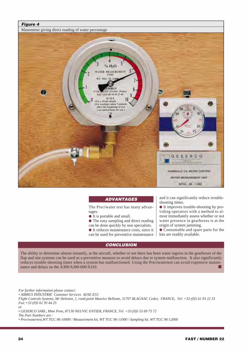
ADVANTAGES
The Preciwater test has many advan-tages:● It is portable and small.● The easy sampling and direct readingcan be done quickly by non specialists.● It reduces maintenance costs, since itcan be used for preventive maintenance
and it can significantly reduce trouble-shooting times.● It improves trouble-shooting by pro-viding operators with a method to al-most immediately assess whether or notwater presence in gearboxes is at theorigin of system jamming.● Consumable and spare parts for thekits are readily available.
FAST / NUMBER 2224
For further information please contact: • AIRBUS INDUSTRIE Customer Services AI/SE-E53 Flight Controls Systems, Mr Deletain, 1, rond-point Maurice Bellonte, 31707 BLAGNAC Cedex, FRANCE, Tel: +33 (0)5 61 93 22 33Fax:+33 (0)5 61 93 44 25 or• GESERCO SARL, Mme Pons, 87130 NEUVIC ENTIER, FRANCE, Tel: +33 (0)5 55 69 75 72The Part Numbers are :• Preciwatertest,WT TGC 96-10000 / Measurement kit, WT TGC 96-11000 / Sampling kit, WT TGC 96-12000
CONCLUSION
The ability to determine almost instantly, at the aircraft, whether or not there has been water ingress in the gearboxes of theflap and slat systems can be used as a preventive measure to avoid delays due to system malfunction. It also significantlyreduces trouble-shooting times when a system has malfunctioned. Using the Preciwatertest can avoid expensive mainte-nance and delays on the A300/A300-600/A310. ■
Figure 4Manometer giving direct reading of water percentage
FAST / NUMBER 22 25
Captain Chris Krahe, Vice PresidentOperational Flight GroupTraining and Flight Operations SupportAirbus Industrie Customer Services Directorate
Pilotsnew to fly-by-wire aircraft tend to askvery legitimate questions concerning theeffect of lightning strikes on the systems
of these technically very advanced aircraft. In general, lightning strikes generate direct and indirect effects on
aircraft.
● The direct effects cause physical damage to the structure of theaircraft. This is due to the high energy content of a bolt of lightningin the span of fractions of a second. The aircraft structure, built torepresent a Faraday Cage, has been thoroughly bonded and inparticular the many parts made of Carbon Fibre Reinforced Plastic(CFRP) have been treated to be electrically conductive by applyingvarious techniques.
Lightning protection of the carbon fiber vertical and horizontaltailplanes is mainly based on the ability of the CFRP material tocarry large amounts of lightning current without suffering damageand the electrical continuity is ensured within the whole structure.
Great effort, therefore, has been spent by Airbus Industrie toensure that lightning current can spread over the whole structureavoiding areas with significant current concentration and makingsure that electrical continuity is maintained at all structural joints.
It has been proven by lightning strike tests on the componentsthemselves, that this design gives a remarkable inherent currentcarrying capability.
● The indirect effects of lightning strikes on aircraft are more likelyto disturb or generate damage to electrical and avionic equipment.This damage is due to the electromagnetic physics generated fromthe circulation of high currents in the structure of the aircraft.
Airbus Industrie and its suppliers of avionics equipment havemade use of the most advanced technology to protect these aircraftagainst external radiation effects such as Electro MagneticInterference (EMI) and lightning strikes.
LIGHTNING STRIKESAND AIRBUSFLY-BY-WIREAIRCRAFT
FAST22 p21/24 11/03/98 22:56 Page 24

FAST / NUMBER 22 27FAST / NUMBER 2226
The effectiveness of the lightningprotection concept was confirmedthrough extensive qualification tests inElectro Magnetic Interference (EMI)chambers. In production and during theentire life time, the function will betested in accordance with acceptancetest procedures.
The Airbus test aircraft were also ex-posed in ground tests to high voltageinduction of several thousand Volts permetre. Thereafter, in a dedicated flighttest campaign, the test aircraft was ex-posed to multiple lightning strikes byseeking purposely to be hit by lightningthrough flight in real thunderstorms orhighly ionized air masses.
Today, the Airbus fly-by-wire aircrafthave accumulated over nine millionflight hours in more than eight years ofairline service. There are nearly 900 ofthese aircraft flying world-wide, and aconsiderable amount of experience withlightning strikes is available.
Like any aircraft in service, they arestruck by lightning.
The experience gathered and the op-erational feedback Airbus Industrie hasreceived from the operators have con-firmed the effectiveness of the conceptand design. We can state today thatthere were virtually no indirect effectson the systems by lightning strikes.
We know of two significant lightningstrike events in the Airbus fleet thatspeak for themselves, and which wewish to share with those interested.
In August 1995, during the interme-diate approach in a thunderstorm intoan airport in Denmark, an A320 was hitby lightning strike - according to thecrew, no aircraft systems were affected.However, the approach had to be inter-rupted with a subsequent diversion toCopenhagen because the destinationairport was hit by lightning as well,which caused a complete electricalblackout including ILS and communi-cation.
On 9 October 1996, an A330-300suffered at least two very severe light-ning strikes while approaching theGreek island of Rhodes where the air-craft made an uneventful landing.
The flight crew reported that duringthese severe lightning strikes, there wasnot the slightest flickering of the dis-plays nor other effects on the avionics
or aircraft systems.However, according to the direct ef-
fects on the structure, Zeus must havehit extremely hard this time. The firstimpact of the lightning on the fuselagewas slightly above door 1R and showedjumps from frame to frame about onemeter above the row of cabin windowsuntil door 3R. On its way, it burned outabout 30 rivets. Apparently, the light-ning left the aircraft on top of the verti-cal fin where it burnt the usual one inchhole. It should be noted that accordingto the operator’s maintenance depart-ment, this lightning hit was the most se-vere suffered across all its aircraft typesduring the company’s 40 years history(Figure 3).
Lightning strikes are by nature un-controllable. They channel their energycontent on a small size pinpoint.Concentration of the energy is thesource of physical damage. All thatlightning strike protection does is todisperse this energy.
Bonding of panels is not meant toavoid damage at all. It is there to evac-uate the static charges generated by airfriction and to provide protectionagainst High Intensity Radiated Fields(HIRF ) in addition to limit damage dueto lightning strikes.
Figure 3Second lightning strike on A330 nose landing gear door
CONCLUSION
The very stringent tests that the Airbus fly-by-wire aircraft were subjected to, have ensured that they can withstand the mostsevere lightning strikes with no effect to their electronic systems, which has been demonstrated in commercial service as thecrew reports demonstrate. ■
The protection of the Airbus aircraftsystems, (electrical distribution) againstindirect effects of lightning strikes rep-resents a quantum leap forward in evo-lution. Segregation of protected compo-nents and separation of wiring lanes isparamount (Figure 1).
System components are protected byfilters allowing only spike-free voltageand current to access the functionalparts of the computer.
An example: during a lightningstrike, voltages may get superimposedon signals that have no lightning pro-tection, and thereby increase the overallsignal levels 500-times. The currentsthat are produced by this phenomenoncan be 300,000-times higher than undernormal conditions. The excess output-power, which the built-in filtering cir-cuits have to neutralize, could have anequivalent magnitude of 500kW,whereas, the total power consumptionof the equipment itself is far below100W under normal conditions.
Airbus Industrie has requested thesuppliers of electronic equipment to de-sign and manufacture them accordingto stringent standards and specificationsthat are considered to be the highest inthe industry.
From the outset and with the designaim of enhanced electronic hardening, aconsiderable amount of research anddevelopment has been invested into thistask. Within the framework of the pos-sibilities that were available, the fol-lowing means have been applied in or-der to guarantee protection againstlightning strikes:● An integrated grounding/shieldingconcept with short connections, and in-ductances that are kept as low as possi-ble.● Guided shields of external cablesright up to the main grounding point ofthe computers.● Symmetrical or separated groundconnections of critical signals (wher-ever possible) with the help of trans-formers, integrated circuits, etc.● Distinctly separated critical electroniccircuits from interference-prone areas(“dirty areas”) through mechanical sep-aration and electrical filtering.● Eradicated voltage surges using suffi-ciently large-sized varistors, transzorbs,or zener diodes in the “dirty areas”.
Generally speaking, the protectiondevice or filter accounts for 25%, thepower supply part for 10 to 20%, andthe pure functional part of the computerrepresents 55 to 65% of the total designeffort (Figure 2).
With respect to the wiring, themethod of double twisted wires runningin metal shielding has successfully beenapplied.
Figure 2Functional parts of a computer
Engine 2Generator
Engine 1Generator
APUGenerator
EmergencyGenerator
1G
2G
6G3GElectrical power centre
Emergency AC-DC power centre
Secondary normal and battery circuit breaker's
APU Generator 3G
Right engineGenerator
Left engineGenerator
1G2G
TR1
Emergency AC-DCpower centre
BATs
ACch.2
DC2
DC1
ACch.1
APU&
EXTPWRch.
6G RAT Generator
Secondary emergency circuit breakers
Main power centre
TR2
Figure 1Segregation of electrical system and components
(With compliments of VDO)
FAST22 p25 � 31 11/03/98 22:27 Page 26
FAST / NUMBER 22 29
with upgrades. This gives the new FMSa large growth potential, matching thatof the ATSU. Across-the-range com-monality and easy upgrades reduce air-line costs. The ability to procure thisnew FMS from two competing suppli-ers is another cost-cutting factor.
The equalization of the retrofit instal-lation into one-shift work packages andthe ability to fly any combination ofFANS-modified / un-modified LRUs.This eases retrofit and cuts its cost.
Thanks to its built-in developmentpotential, the AIM-FANS A configura-tion entering service this year on theA330/A340 will seamlessly evolve bythe year 2000 to the AIM-FANS B con-figuration, fully compliant with theATN (Aeronautical TelecommunicationNetwork).
No AIM-FANS A step is planned atthis stage for the A320 family but a di-rect move to AIM-FANS B by 2000,because the type of route on which theaircraft is operated will likely requirethe ATN directly. The A320 family,however, will be fitted with a “Pre-FANS” installation a few months afterthe A330/A340 receives AIM-FANS A.It will consist of the ATSU with AOC
functions, the new FMS, re-arrangedcockpit instrument panels ready to ac-cept the installation of AIM-FANS con-trols and displays, and wiring provi-sions. This will make the futureinstallation of AIM-FANS B easier forcustomers and will also allow speedyinstallation of AIM-FANS A on theA320 family, if finally needed. ■
With AIM-FANS, Controller-Pilot communication isachieved via two Datalink Control and Display Units
(DCDUs), the screens visible at the bottom of the centre instrument panel of this A340 flight deck. They provide
each crew member with a dedicated interface for ATC com-munication. This arrangement has been selected for its user-
friendliness and its ability to cope with the busy Air TrafficControl environments to which FANS will soon spread.
Flight testing of AIM-FANS has started and will lead to certification ofthe system in the second half of 1998.
irline involvement in the devel-opment of the Airbus Interop-erable Modular - Future AirNavigation System (AIM-
FANS) avionics suite, which is due toenter service this year on the A330 andA340, has been key to its present suc-cess.
A core team of seven major Airbuscustomers has been working in closeco-operation with Airbus on all aspectsof the programme: system design,schedules, product support and com-mercial. In addition, a series of semi-annual review conferences allowed thecollection of further valuable inputsfrom all customers.
Customers generally confirmed thevalidity of the basic concept presentedin FAST 17 (issue December 94) withits major benefits of operational flexi-bility, development potential and com-monality, but added inputs which sig-nificantly improved the value of theAIM-FANS product. A few examplesare:● The tuning of the design and sched-ules of AIM-FANS to provide the rightFANS functionality at the right time ineach region of the world. This resultsfrom the progressive development of acommon understanding by the group of
the various FANS environments nowemerging around the world.● The use of VHF Data Radios (VDR)instead of VHF radios. This makesAIM-FANS consistent with airlines’general move towards VDRs and en-hances its development potential● The incorporation of the AircraftCommunication Adressing andReporting System (ACARS) AirlineOperational Communication (AOC)functions into the Air Traffic ServicesUnit (ATSU, the AIM-FANS commu-nication management box). This re-moves the need for a separate ACARSbox, which simplifies the overall archi-tecture of the aircraft communicationsystem and reduces airline costs.Competition between three AOC soft-ware suppliers further reduces costs.● The development of a crew-friendlyFANS cockpit arrangement, able tosupport later developments of FANS,avoiding the need of burdening andcostly downstream reshuffling of cock-pit configuration and operational phi-losophy.● The introduction of a new FlightManagement System (FMS), commonto the A330/A340 and A320 family,with greatly increased computingpower, memory size and ability to cope
FAST / NUMBER 2228
Jean-Pierre DambrineProduct Marketing DirectorAirbus Industrie
AA
AIM-FANS AIM-FANS WINSWINSGROWINGGROWINGNUMBERNUMBEROF OF ORDERSORDERSAIM-FANS customers (full installation), as of early December 97. The list is growing rapidly.
International
FAST22 p25 � 31 11/03/98 22:32 Page 28
FAST / NUMBER 22 31FAST / NUMBER 2230
Over 430 representatives from 64airlines, 46 vendors and Airbus Industrieattended this conference. This Symposium was hosted by Roger LECOMTE, Vice PresidentEngineering and Technical Support andchaired by Thierry HÉRAULT, DirectorA320 Program from Airbus Customer
Services. From the 500 inputs received from the operatorsprior to the Symposium, 60 subjects were retained for formalpresentations and discussion during the plenary sessions and around 25 subjects were reviewed in side meetings. In addition, written answers to remaining questions weregiven in the documentation provided to each participants.
Several sessions were devoted to present the new Airbus Technical Information System (ATIS) and SinglePoint of Contact (SPOC) concept for on-line access. These presentations were supported by true on-linedemonstration of on-line access to Service Bulletins andTechnical Follow-Up.
Following tradition at the opportunity of the openingceremony, Bernard CATTEEUW, Senior Vice President ofAirbus Customer Services, presented awards to A319, A320and A321 operators for excellent achievements obtained bysome operators.
The awards for OPERATIONAL EXCELLENCE was given to:● AIR FRANCE for the A319.● ALL NIPPON AIRWAYS for the A320.● SWISSAIR for the A321.
In addition SPECIAL RECOGNITION was given to:● CANADA 3000 for the highest yearly utilisation in flighthours achieved with the A320: around 4500 flight hoursper aircraft and per year.● TRANSASIA AIRWAYS for the highest yearly utilisation inflight cycles achieved with A321: more than 3300 flightcycles per aircraft and per year.● SKYSERVICE for the highest average flight time achieved with an A320: 3.3 hours per flight.
All the latter demonstrates the very high versality of the A320family.
Over 400 delegates from 60 airlines, 98 suppliers, Airbus Industrie and its partnersgathered recently for the fourth MaterielsSymposium. The conference, which was thelargest and most successful of its kind, providedan open forum for all parties involved in the Airbus Industrie supply chain to discuss a wide range of issues related to materielsmanagement, with an emphasis on the need to achieve an effective balance between cost-reduction and service.
Speaking at the conference, Peter KLOEPFER, VicePresident Material Support, announced that continued cost-reduction at the industrial level, combined with improvedefficiency in administration and manufacturing processes,would mean that average material cost expenditure for AirbusIndustrie proprietary parts in 1998 would once again remain
at 1991 levels. Peter KLOEPFER also praised the efforts of thirdparty suppliers in recent years to support Airbus Industrie'scost-reduction and service enhancement initiatives.
"Each year since 1995 a significant number of AirbusIndustrie suppliers have applied zero escalation on theirprices," he said. "At the same time many of the suppliers havealso responded positively to customer requirements forreduced shop processing times, improved part reliability andmore flexible support contracts."
The Suppliers which had shown the strongestcommitment and support for Airbus Industrie initiativeswere recognised at a special gala dinner with awardspresented by Bernard CATTEEUW to:● DASA KID SYSTEMS
● DIEHL
● VIBROMETER
● SULLY PRODUITS SPÉCIAUX.
Providing an opportunity for the operators, suppliers and Airbus Industrie staff to discuss technical subjects ofcommon interest and share in-service experience.
MATERIEL SUPPORT SYMPOSIUM14-17 SEPTEMBER 1997 IN KUALA-LUMPUR
A330/A340 TECHNICAL SYMPOSIUM11-15 MAY 1998 IN KUALA-LUMPUR
"It shall be unlawful tomanufacture and lift-offballoons and other aerostaticmachines with heaters usingwine spirit, fire crackers andother flammable materials,and orders that all otheraerostatic balloons may nottake-off withoutpermission".
April 23, 1784The headquarters of Paris Police
First flight of the “Globe Aërostatique” from Versailles on 19 September 1783
The FirstAviationRegulation?
A319/A320/A321 TECHNICAL SYMPOSIUM8-12 DECEMBER 1997 IN SAN FRANCISCO
FAST22 p25 � 31 11/03/98 22:36 Page 30
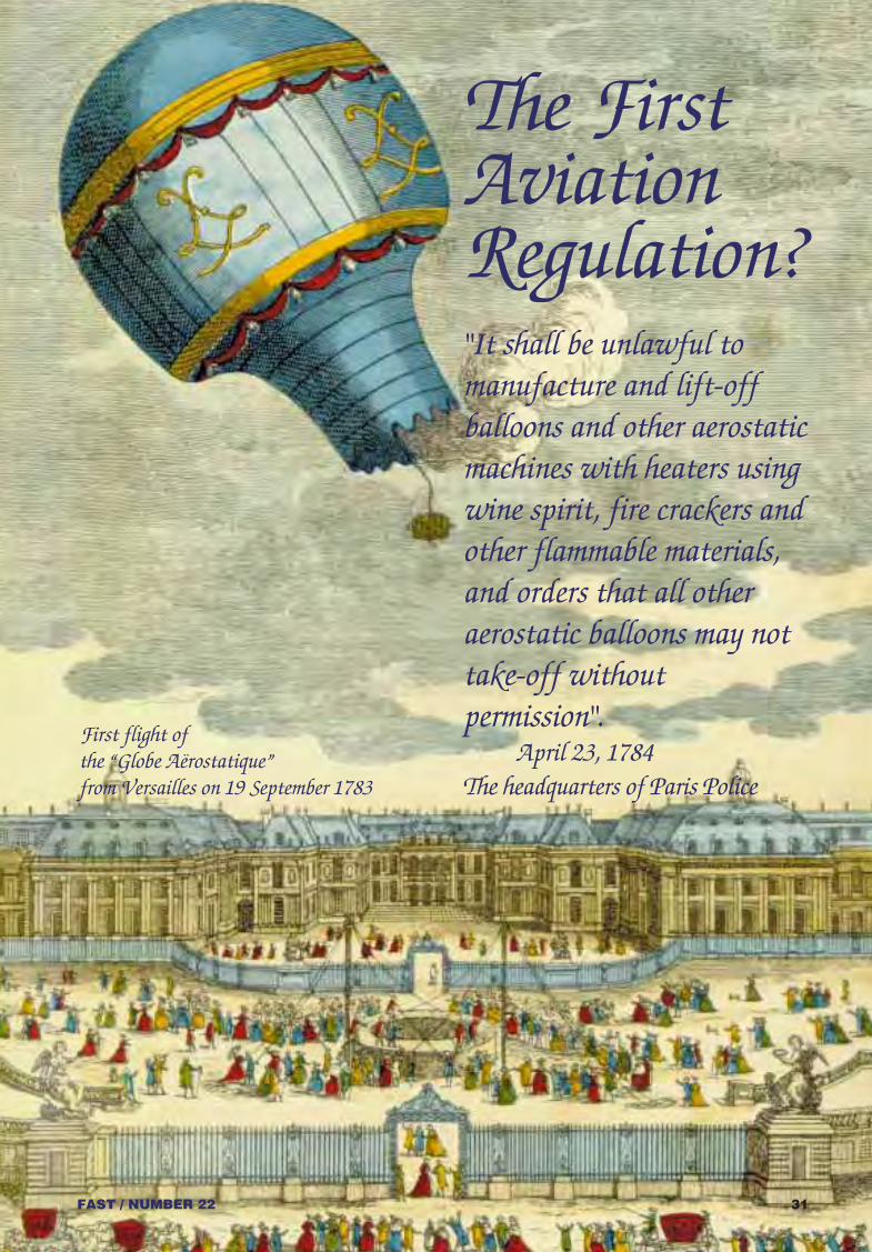

RESIDENTCUSTOMERSUPPORTREPRESENTATIONMohamed El-Boraï, Vice President Customer Support Services DivisionTelephone: +33 (0)5 61 93 35 04 / Telefax: +33 (0)5 61 93 41 01Jean-Paul Gayral, Resident Customer Representation Administration DirectorTelephone: +33 (0)5 61 93 38 79 / Telefax: +33 (0)5 61 93 49 64Airbus Industrie headquarters1 rond-point Maurice Bellonte, 31707 Blagnac Cedex France
32 FAST / NUMBER 22 33FAST / NUMBER 22
LOCATION COUNTRY TELEPHONE TELEFAXABU DHABI United Arab Emirates 971 (2) 706 7702 971 (2) 757 097 AMMAN Jordan 962 (8) 51 284 962 (8) 51 195 ATHENS Greece 30 (1)981 8581 30 (1) 983 2479 BANGKOK Thailand 66 (2) 531 0076 66 (2) 531 1940BEIJING Peoples Republic of China 86 (10) 6457 2688 86 (10) 6457 0503BEIRUT Lebanon 961 (1) 601 300 961 (1) 601 200BOGOTA Columbia 57 (1) 414 8195/96 57 (1) 414 8094 BOMBAY (MUMBAI) India 91 (22) 618 3273 91 (22) 611 3691BRUSSELS Belgium 32 2723 4824/25/26 32 2723 4823BUCHAREST Romania 40 (1) 312 6670 40 (1) 312 6670 BUENOS AIRES Argentina 54 (1) 480 9408 54 (1) 480 9408 CAIRO Egypt 20 (2) 418 3687 20 (2) 418 3707CHENGDU Peoples Republic of China 86 (28) 570 3851 86 (28) 521 6511CHICAGO USA (Illinois) 1 (773) 601 4602 1 (773) 601 2406COLOMBO Sri Lanka 94 73 2197 / 2199 94 (1) 253 893 DAKAR Senegal 221 8201 615 221 8201 148 DAKHA Bangladesh 880 (2) 896129 880 (2) 896130DELHI India 91 (11) 565 2033 91 (11) 565 2541 DETROIT USA (Michigan) 1 (313) 247 5090 1 (313) 247 5087DUBAI United Arab Emirates 971 (4) 244806 971 (4) 244806 DUBLIN Ireland 353 (1) 705 2294 353 (1) 705 3803 DULUTH USA (Minnesota) 1 (218) 733 5077 1 (218) 733 5082DUSSELDORF Germany 49 (211) 9418 687 Ext. 751 49 (211) 9418 035FRANKFURT Germany 49 (69) 696 3947 49 (69) 696 4699GUANGZHOU Peoples Republic of China 86 (20) 8612 8813 86 (20) 8612 8809GUAYAQUIL Ecuador 593 (9) 744 734 593 (4) 290 432HANGHZOU Peoples Republic of China 86 (571) 514 5876 86 (571) 514 5916HANOI Vietnam 84 (48) 731 613 84 (48) 731 612HO CHI MINH CITY Vietnam 84 (8) 84 57 602 84 (8) 84 46 419 HONG KONG Hong Kong 852 2747 8449 852 2352 5957 ISTANBUL Turkey 90 (212) 574 0907 90 (212) 573 5521 JAKARTA Indonesia 62 (21) 550 1993 62 (21) 550 1943 JEDDAH Saudi Arabia 966 (2) 684 2864 966 (2) 685 7712 JOHANNESBURG South Africa 27 (11) 978 3193 27 (11) 978 3190 KARACHI Pakistan 92 (21) 457 0604 92 (21) 457 0604 KINGSTON Jamaica 1 (876) 924 8057 1 (876) 924 8154KUALA LUMPUR Malaysia 60 (3) 746 7352 60 (3) 746 2230 KUWAIT Kuwait 965 474 2193 965 434 2567 LARNACA Cyprus 357 (4) 643 181 357 (4) 643 185 LISBON Portugal 351 (1) 840 7032 351 (1) 847 4444 LONDON (LHR) England 44 (181) 751 5431 44 (181) 751 2844 LOS ANGELES USA (California) 1 (310) 342 8504 1 (310) 578 9072 LUTON England 44 (1582) 39 8706 44 (1582) 70 6173 MACAO Macao 853 898 4023 853 898 4024
LOCATION COUNTRY TELEPHONE TELEFAXMADRID Spain 34 (1) 329 1447 34 (1) 329 0708 MANCHESTER England 44 (161) 489 3155 44 (161) 489 3240MANILA Philippines 63 (2) 831 5444 63 (2) 831 0834 MAURITIUS Mauritius 230 637 8542 230 637 3882MEDELIN Columbia 57 (4) 5361027 57 (4) 5361024MEMPHIS USA (Tennessee) 1 (001) 224 4842 1 (901) 224 5018 MEXICO CITY Mexico 52 (5) 784 3874 52 (5) 785 5195 MELBOURNE Australia 61 (3) 9338 2038 61 (3) 9338 0281 MIAMI USA (Florida) 1 (305) 871 1441 1 (305) 871 2322 MINNEAPOLIS USA (Minnesota) 1 (612) 726 0431 1 (612) 726 0414 MONTREAL Canada 1 (514) 422 6320 1 (514) 422 6310 MOSCOW Russia 7 (095) 753 8061 7 (095) 753 8006 MUSCAT Oman 968 521 286 968 521 286NAIROBI Kenya 254 (2) 822 763 254 (2) 822 763 NEW YORK USA (New York) 1 (718) 656 0700 1 (718) 656 8635 NUREMBERG Germany 49 (911) 365 6219 49 (911) 365 6218PARIS (CDG) France 33 (0)1 48 62 08 82 / 87 33 (0)1 48 62 08 99 PARIS (ORY) France 33 (0)1 49 78 02 88 33 (0)1 49 78 01 85 PHOENIX USA (Arizona) 1 (602) 693 7445 1 (602) 693 7444 PUSAN South Korea 82 (51) 971 6977 82 (51) 971 4106 ROME Italy 39 (6) 6501 0564 39 (6) 652 9077 SAN’A Yemen 967 (1) 344 439 967 (1) 344 439SAN FRANCISCO USA (California) 1 (650) 6344375/76/79 1 (650) 6344378 SAN JOSE Costa Rica 506 (4) 417 223 506 (4) 412 228 SAN SALVADOR El Salvador 503 3399335 503 3399627SAO PAULO Brasil 55 (11) 644 54 364 55 (11) 644 54 363SEOUL South Korea 82 (2) 665 4417 82 (2) 664 3219 SHANGHAI Peoples Republic of China 86 (21) 6268 4122 86 (21) 6268 6671 SHANNON Ireland 353 (1) 705 2084 353 (1) 705 2085 SHENYANG Peoples Republic of China 86 (24) 272 5177 86 (24) 272 5177SINGAPORE Singapore 65 (5) 455 027 65 (5) 425 380 TAIPEI Taiwan 886 (3) 383 4410 886 (3) 383 4718 TASHKENT Uzbekistan 7 (37) 1254 8552 7 (37) 1255 2878 TEHRAN Iran 98 (21) 603 5647 98 (21) 603 5647 TOKYO (HND) Japan 81 (3) 5756 5081 81 (3) 5756 5084
81 (3) 5756 8770 81 (3) 5756 8772TORONTO Canada 1 (905) 677 8874 1 (905) 677 1090 TULSA USA (Oklahoma) 1 (918) 292 3227 1 (918) 292 2581 TUNIS Tunisia 216 (1) 750 639 216 (1) 750 855 VANCOUVER Canada 1 (604) 276 3776 1 (604) 276 3548 VIENNA Austria 43 (1) 7007 3688 43 (1) 7007 3235 WINNIPEG Canada 1 (204) 985 5908 1 (204) 837 2489 XIAN Peoples Republic of China 86 (29) 870 7651 86 (29) 870 7255ZURICH Switzerland 41 (1) 812 7727 41 (1) 810 2383
FAST22 p25 � 31 11/03/98 22:39 Page 32
1998SPARES COSTS
STILL AT1991 LEVELS.
AIRBUS INDUSTRIE
AIRBUSTECHNICALDIGEST
NUMBER 22MARCH 1998
Airbus Industrie’s improved production technology has helped
to reduce the proprietary spares expenses for Airbus
operators every year since 1994 to average 1991 levels.
So you can keep your Airbus aircraft in the air and
your operating costs firmly on the ground.
SETTING THE STANDARDShttp://www.airbus.com/
Cover FAST 11/03/98 21:55 Page 1