correlation of ccv between in-cylinder swirl ratio and … · les4ice'16: les for internal...
TRANSCRIPT

★ Paper presented at: Large-Eddy Simulation for InternalCombustion Engines, Rueil-Malmaison, France, 30 November –1 December 2016.
Oil & Gas Science and Technology - Rev. IFP Energies nouvelles (2017) 72, 38© X. Yang and T.-w. Kuo, published by IFP Energies nouvelles, 2017DOI: 10.2516/ogst/2017036
This is an Open Access article distributed under the terms of the Creative Cowhich permits unrestricted use, distribution, and reproduction i
Do s s i e r
LES4ICE'16: LES for Internal Combustion Engine Flows ConferenceCorrelation of CCV Between In-Cylinder Swirl Ratioand Polar Velocity Profile in Valve Seat RegionUsing LES Under Motored Engine Condition★
Xiaofeng Yang*,
and Tang-Wei KuoGM Global R&D, 800N Glenwood Ave., MI 48340-2925, Pontiac – USAe-mail: [email protected]
*Corresponding author
Abstract — An analysis of Transparent Combustion Chamber (TCC3) engine Large-Eddy Simulation(LES) result was carried out to investigate Cycle-to-Cycle Variation (CCV) correlation between in-cylinder swirl ratio and flow in the valve seat region of the intake port to address a challenging questionon “What causes CCVof in-cylinder flow”. Polar Velocity (PV) profile, mean velocities normal to a ring-shaped cutting surface in the valve seat region, is calculated to depict intake port flow. A Net PolarVelocity (NPV) can be defined by performing the vector sum of the polar velocity around the intake valve.A standard deviation of PVis also calculated from azimuthal distribution of PV magnitudes relative to itsmean value. The analysis of 18 LES cycles of TCC3 engine with a two-valve, pancake-shapedcombustion chamber shows that similar CCVof in-cylinder swirl ratio patterns are observed at differentcrank angles from Intake Valve Opening (IVO) to Exhaust Valve Opening (EVO). Further analysis showsclear correlations of CCV between in-cylinder swirl ratio and NPV magnitude and the standarddeviation of PVat selected crank angles from IVO to EVO. The correlations get significantly better withthe ring-shaped cutting surface moves from up-stream to downstream of the valve-seat region. This studyreveals that the CCVof in-cylinder swirl ratio is built up gradually from upstream to downstream in theintake port and valve-seat region. Further evaluation of the analysis method is planned for a four-valveengine as an evaluation metric for better engine intake port design and combustion chamberoptimization.
INTRODUCTION
New automotive engine technologies promise to achieveimproved fuel economy with reduced emissions. However,these technologies are more sensitive to stochastic processesand can suffer from increased cyclic variability. Large-EddySimulation (LES) is an important computational tool forunderstanding the critical processes that impact cyclicvariability, and eventually can be used to mitigate theiroccurrence.
n
The computational tool of LES has been increasinglyresearched and developed for the last two decades [1] forbetter in-cylinder flow predictions. LES captures Cycle-to-Cycle Variations (CCV) as opposed to cycle-averaged meancomputations of RANS, and is therefore more accurate. Arecent effort of GM’s R&D and other organizations has beento understand and describe the nature of stochastic flows ininternal combustion engines through concerted ParticleImage Velocimetry (PIV) measurements and LES [2–9].
There are various intrinsic flow features inside an ICengine cylinder like swirl, tumble, intake jet, compressionflow from piston, etc. which can be sources of the CCVof in-cylinder flows. Present paper develops an analysis procedureto evaluate the effects of intake port flow on CCVof the swirlratio, based on LES results of motored Transparent
mmons Attribution License (http://creativecommons.org/licenses/by/4.0),any medium, provided the original work is properly cited.

Figure 1
Schematics of Transparent Combustion Chamber (TCC3)engine.
Figure 2
CFD model of TCC3 engine.
Page 2 of 10 Oil & Gas Science and Technology - Rev. IFP Energies nouvelles (2017) 72, 38
Combustion Chamber (TCC3) engine. The overall goal is todevelop physics-based computational tools for a moreeffective design of internal combustion engines of the future.
In an attempt to work towards providing elements foranswering the question of what causes CCV of in-cylinderflows, the following questions were explored:
– Is there any correlation of CCV between in-cylinder swirlratios at different crank angles during the four-strokecycle?–
Is there any correlation of CCV between in-cylinder swirlratio and intake port flow?1 TCC3 ENGINE
An optical engine test setup was developed for the specificpurpose of supporting the development and validation of arange of LES approaches [2,3]. The test setup features a singlecylinder optical engine connected to intake and exhaustplenumsvia intake and exhaust runners, respectively. Figure 1shows the engine features: a two-valve head and simple intakeandexhaustport geometrieswithapancake-shapecombustionchamber coupled with a full quartz liner for maximum opticalaccess. The engine has a bore of 92mm, a stroke of 86mmandintake and exhaust valve diameter of 30mm. The geometriccompression ratio is 10.0. Previous work [9] gives details ofthe other parameters like intake and exhaust valve lift profiles,engine specifications and intake and exhaust geometries.
2 CFD SETUP AND VALIDATION
A commercial CFD code CONVERGE v2.1 [10] is used forthis LES study of engine in-cylinderflows. CONVERGEusesa modified cut-cell Cartesian method that eliminates the needfor the computational grid to bemorphedwith the geometry ofinterestwhile still properly representing the geometry [11].Atruntime, CONVERGE uses the supplied triangulated surfaceto cut the cells into a smaller irregular cells (i.e. cut-cell) thatare intersected by the surface. Any cell can be cut by anarbitrary number of surface triangles, thus allowing the grid torepresent the boundary accurately. All computed values arecollocated at the center of the computational cell. To preventchecker boarding, the Rhie and Chow [12] algorithm isemployed. All of the conservation equations are solved usingthe finite volume method. In finite volume mode, spatialderivatives are calculated by blending 2nd order scheme.CONVERGEutilizes an implicit time integration scheme, andduring the exhaust stroke the maximum CFL number wasdoubled (from 1 to 2) to reduce computation time. Thetransport equations are solved using the Pressure Implicit withSplitting of Operators (PISO) method of Issa [13]. The one-equation eddy viscosity dynamic structure turbulence model[14] is used for the LES with the Werner and Wengle wallmodel [15] to handle the flow and thermal boundary layers.CONVERGE can be run in parallel on shared memorymachines. The parallelization is done using Message PassingInterface (MPI) so that both shared and distributed machinescan be used for parallel runs.The wave dynamics of completeengine experimental setup is simulated with GT-Power, adetailed 1-D flow model. The 1-D model is validated with
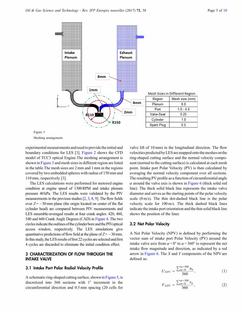
Figure 3
Meshing arrangement.
Oil & Gas Science and Technology - Rev. IFP Energies nouvelles (2017) 72, 38 Page 3 of 10
experimentalmeasurements andused toprovide the initial andboundary conditions for LES [3]. Figure 2 shows the CFDmodel of TCC3 optical Engine.The meshing arrangement isshown in Figure 3 andmesh sizes in different region are listedin the table.The mesh sizes are 2mm and 1mm in the regionscovered by two embedded spheres with radius of 150mm and110mm, respectively [3].
The LES calculations were performed for motored enginecondition at engine speed of 1300RPM and intake plenumpressure 40kPa. The LES results were validated by the PIVmeasurements in the previous studies [2, 3, 8, 9]. The flow fieldsover Z=�30mm plane (the origin located on center of the flatcylinder head) are compared between PIV measurements andLES ensemble-averaged results at four crank angles: 420, 460,540 and 660 Crank Angle Degrees (CAD) in Figure 4. The twocircles indicate theoutlinesof thecylinderboreandthePIVopticalaccess window, respectively. The LES simulations givequantitative predictions offlowfield at the plane ofZ=�30mm.In this study, theLESresultsoffirst 22cycles are selectedandfirst4 cycles are discarded to eliminate the initial condition effect.
3 CHARACTERIZATION OF FLOW THROUGH THEINTAKE VALVE
3.1 Intake Port Polar Radial Velocity Profile
A schematic ring-shapedcutting surface, shown inFigure 5, isdiscretized into 360 sections with 1° increment in thecircumferential direction and 0.5mm spacing (20 cells for
valve lift of 10mm) in the longitudinal direction. The flowvelocitiespredictedbyLESaremappedonto themesheson thering-shaped cutting surface and the normal velocity compo-nent (normal to the cutting surface) is calculated at each meshpoint. Intake port Polar Velocity (PV) is then calculated byaveraging the normal velocity component over all sections.The resulting PVprofile as a function of circumferential anglea around the valve axis is shown in Figure 6 (thick solid redline). The thick solid black line represents the intake valvediameter and serves as the starting points of the polar velocityscale (0m/s). The thin dot-dashed black line is the polarvelocity scale for 100m/s. The thick dashed black linesindicate the intake port orientation and the thin solid black lineshows the position of the liner.
3.2 Net Polar Velocity
A Net Polar Velocity (NPV) is defined by performing thevector sum of intake port Polar Velocity (PV) around theintake valve axis from a= 0° to a= 360° to represent the netintake flow magnitude and direction, as indicated by a redarrow in Figure 6. The X and Y components of the NPV aredefined as:
UNPV ¼Pa¼360
a¼0 ua360
; ð1Þ
VNPV ¼Pa¼360
a¼0 va360
; ð2Þ

Figure 4
Comparison of velocity field over Z=�30mm plane between PIV data and LES results.
Page 4 of 10 Oil & Gas Science and Technology - Rev. IFP Energies nouvelles (2017) 72, 38
where ua, va are x and y components of the polar velocity ineach section. NPV angle u in Figure 6 is the angle betweenthe NPV and the negative X-axis and is defined as:
u ¼ ATANVNPV
UNPV
� �: ð3Þ
4 ANALYSIS AND RESULTS
4.1 CCV Pattern of In-Cylinder Swirl Ratios
Figure 7A shows the in-cylinder swirl ratios of18 consecutive LES cycles and the valve lift profiles infunction of crank angle. Analysis of 18 consecutive LEScycles indicated two distinct CCV patterns of in-cylinderswirl ratios (SR CCV patterns). Different SR CCV patterns
are evident as illustrated in Figure 7B and C at four selectedcrank angles during both the exhaust (210, 240, 270 and300CAD), intake and compression (390, 460, 540 and660 CAD) strokes, respectively. In particular, the intake SRCCV patterns at different crank angles behave qualitativelysimilar with differences only in their magnitudes. The samecannot be said for the exhaust SR CCV patterns. The intakeSR CCVat 460CAD (SR CCV (460)) is chosen as a baselineto evaluate its correlations with the intake SR CCV atdifferent crank angles, SR CCV (CAD).
This is because of significant back flow from the exhaustport into the cylinder when the exhaust valve opens.Figure 8 shows the instantaneous Mass Flow Rates (MFR)of intake and exhaust ports for 18 LES cycles as a functionof crank angle, positive for entering the cylinder andnegative for leaving the cylinder. The peak exhaust MFR of

Figure 5
Schematic ring-shaped cutting surface in the valve seat region.
Figure 6
Intake port Polar Velocity (PV) profile and Net Polar Velocity(NPV) for LES cycle #17 at 460CAD.
Figure 7
In-cylinder swirl ratios of 18 LES cycles. a) In-cylinder swirl ratios of 18 consecutive LES cycles and value lift profiles in function of crankangle. b) SR CCV patterns at 4 selected crank angles during exhaust stroke. c) SR CCV patterns at 4 selected crank angles during intake andcompression strokes.
Oil & Gas Science and Technology - Rev. IFP Energies nouvelles (2017) 72, 38 Page 5 of 10
60 g/s is about 3 times higher than the peak intake MFR of20 g/s. The MFR curves of the 18 LES cycles are almostidentical, with a standard deviations of 0.237 and 0.047 at
180 and 450 CAD, respectively. The effect of cyclicvariability of MFR on in-cylinder SR CCV patterns can beignored.

Figure 8
Mass flow rates of intake and exhaust ports for 18 LES cyclesas a function of crank angle, positive for entering cylinder andnegative for leaving cylinder.
Figure 9
PPMCC (RAD) between SR CCV (CAD) and SR CCV (CAD)in function of crank angle.
Page 6 of 10 Oil & Gas Science and Technology - Rev. IFP Energies nouvelles (2017) 72, 38
The Pearson Product Moment Correlation Coefficient(PPMCC) is a measure of the linear correlation betweenpairs of continuous variables giving a value betweenþ1 and�1, where 1 is perfectly positive linear relationship, 0 is norelationship, and�1 is perfectly negative linear relationship.The correlation coefficient PPMCC (CAD) between SRCCV(460) and SR CCV(CAD) of 18 cycles is computed as:
see equation (4) bottom
where SRCCVð460Þ and SRCCVðCADÞ are the averagevalues of the SR CCV(460) and SR CCV (CAD) of 18cycles.
PPMCC (CAD) is shown as a function of crank angle inFigure 9. During most of the time span between Intake ValveOpening (IVO) and Exhaust Valve Opening (EVO) at about360 CAD, the PPMCC exhibits values around or higher than0.87. This indicates that the intake port flow CCV dominatesthe in-cylinder flow CCV during this time. After EVO thePPMCC value drops down to 0.4 near 180 CAD, andeventually rises up to about 0.8 during the latter part of theexhaust stroke. By comparing the mass flow rates of intakeand exhaust ports in Figure 8, the drastic reduction ofPPMCC is caused by a back flow from the exhaust port intothe cylinder, and the recovery is due to flow reversal from thecylinder to the exhaust port.
PPMCC ðCADÞ ¼PðSRCCV ð460Þ � SRCCV ð460ÞffiffiffiffiffiffiffiffiffiffiffiffiffiffiffiffiffiffiffiffiffiffiffiffiffiffiffiffiffiffiffiffiffiffiffiffiffiffiffiffiffiffiffiffiffiffiffiffiffiffiffiffiffiffiffiffiffiffiffiffiffiffiffiffiffiffiffiffiffiffiffiffiffiffiffiffiffiP ðSRCCV ð460Þ � SRCCV ð460ÞÞ2q
⋅ffiffiPq
In summary, it is observed that the intake flow dominatesthe intake SR SCCV patterns from IVO to EVO. It is alsoobserved that the exhaust SR CCV patterns has limitedimpact on the intake SR CCV patterns as shown in Figure 7.
4.2 Intake Port Polar Velocity Profile in Different Ring-Shaped Cutting Surface in Valve-Seat Region
In order to investigate the effect of intake port flow in thevalve-seat region on the intake SR CCV, six ring-shapedcutting surfaces (Stem1, Stem2, Valve3, Valve4, Valve5and Valve6) are created at 460 CAD as shown inFigure 10 for the intake port polar velocity analysis(Fig. 11).
Figure 11 shows the intake port PVprofiles at 460CAD forthe six ring-shaped cutting surfaces in the valve-seat region ofcycle #17 as a function of valve circumferential angle. TheNPVforeach ring-shapedcutting location is alsoplottedas redarrows.ThePVmagnitudedecreasesgradually fromupstreamto downstream of the valve seat region due to increase in theflow area. The NPV magnitudes are quite small at locationsStem1 and Stem2 due to near uniform PV profile at thosecutting planes. The NPV magnitudes are larger at locationsValve3 to Valve6 because of flow inhomogeneity caused bythe offset intake valve position (Fig. 2).
ÞðSRCCV ðCADÞ � SRCCV ðCADÞÞffiffiffiffiffiffiffiffiffiffiffiffiffiffiffiffiffiffiffiffiffiffiffiffiffiffiffiffiffiffiffiffiffiffiffiffiffiffiffiffiffiffiffiffiffiffiffiffiffiffiffiffiffiffiffiffiffiffiffiffiffiffiffiffiffiffiffiffiffiffiffiffiffiffiffiffiffiffiffiffiffiffiffiðSRCCV ðCADÞ � SRCCV ðCADÞÞ2;
ð4Þ

Figure 10
Ring-shaped cutting surfaces in valve-seat region at 460CAD.
Figure 11
PV and NPV at the six ring-shaped cutting surfaces of cycle #17 at 460CAD.
Oil & Gas Science and Technology - Rev. IFP Energies nouvelles (2017) 72, 38 Page 7 of 10
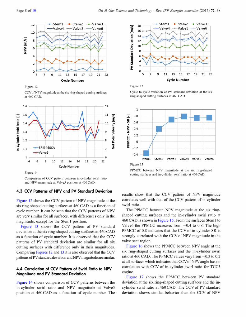
Figure 12
CCVof NPV magnitude at the six ring-shaped cutting surfacesat 460 CAD.
Figure 13
Cycle to cycle variation of PV standard deviation at the sixring-shaped cutting surfaces at 460CAD.
Figure 14
Comparison of CCV pattern between in-cylinder swirl ratioand NPV magnitude at Valve5 position at 460CAD.
Figure 15
PPMCC between NPV magnitude at the six ring-shapedcutting surfaces and in-cylinder swirl ratio at 460CAD.
Page 8 of 10 Oil & Gas Science and Technology - Rev. IFP Energies nouvelles (2017) 72, 38
4.3 CCV Patterns of NPV and PV Standard Deviation
Figure 12 shows the CCV pattern of NPV magnitude at thesix ring-shaped cutting surfaces at 460CAD as a function ofcycle number. It can be seen that the CCV patterns of NPVare very similar for all surfaces, with differences only in themagnitude, except for the Stem1 position.
Figure 13 shows the CCV pattern of PV standarddeviation at the six ring-shaped cutting surfaces at 460CADas a function of cycle number. It is observed that the CCVpatterns of PV standard deviation are similar for all sixcutting surfaces with difference only in their magnitudes.Comparing Figures 12 and 13 it is also observed that the CCVpatternsofPVstandarddeviationandNPVmagnitudearesimilar.
4.4 Correlation of CCV Pattern of Swirl Ratio to NPVMagnitude and PV Standard Deviation
Figure 14 shows comparison of CCV patterns between thein-cylinder swirl ratio and NPV magnitude at Valve5position at 460CAD as a function of cycle number. The
results show that the CCV pattern of NPV magnitudecorrelates well with that of the CCV pattern of in-cylinderswirl ratio.
The PPMCC between NPV magnitude at the six ring-shaped cutting surfaces and the in-cylinder swirl ratio at460CAD is shown in Figure 15. From the surfaces Stem1 toValve6 the PPMCC increases from �0.4 to 0.8. The highPPMCC of 0.8 indicates that the CCV of in-cylinder SR isstrongly correlated with the CCVof NPV magnitude in thevalve seat region.
Figure 16 shows the PPMCC between NPV angle at thesix ring-shaped cutting surfaces and the in-cylinder swirlratio at 460CAD. The PPMCC values vary from�0.3 to 0.2at all surfaces which indicates that CCVof NPVangle has nocorrelation with CCV of in-cylinder swirl ratio for TCC3engine.
Figure 17 shows the PPMCC between PV standarddeviation at the six ring-shaped cutting surfaces and the in-cylinder swirl ratio at 460CAD. The CCV of PV standarddeviation shows similar behavior than the CCV of NPV

Figure 16
PPMCC between NPV angle at the six ring-shaped cuttingsurfaces and in-cylinder swirl ratio at 460CAD.
Figure 17
PPMCC between PV standard deviation at the six ring-shapedcutting surfaces and in-cylinder swirl ratio at 460CAD.
Oil & Gas Science and Technology - Rev. IFP Energies nouvelles (2017) 72, 38 Page 9 of 10
magnitude presented in Figure 15. It further indicated thatcorrelation of CCV patterns between the port flow in thevalve seat region and the in-cylinder swirl ratio is built upgradually from section Stem1 to Valve6, i.e. from upstreamto downstream in the valve-seat region for the intake portexamined. In other words, CCV of flow in the valve seatregion for the TCC3 engine dominates the CCV of in-cylinder swirl ratio.
CONCLUSION
An analysis of TCC3 engine LES results was carried out toinvestigate CCV correlation between in-cylinder swirl ratioand flow in the valve seat region of the intake port. A polarvelocity profile at selected ring-shaped cutting surfaces inthe valve seat region was calculated as an indicator of portflow uniformity. A net polar velocity was defined byperforming the vector sum of the polar velocity on the ring-shaped cutting surface. A standard deviation of PV was alsocalculated from azimuthal distribution of PV magnitudesrelative to its mean value. The following observations werereached:
– Strong correlation exists between CCV patterns of in-cylinder swirl ratio at different crank angle positions fromIVO to EVO, which suggests the in-cylinder flow CCV isdominated by the intake flow;–
CCVof in-cylinder swirl ratio at all crank angle positionsfrom IVO to EVO also exhibits strong correlation with thenet polar velocity magnitude and polar velocity standarddeviation. The correlation improves when the ring-shapedcutting surface is moved from upstream to downstream inthe valve seat region.This study reveals that there is strong correlation betweenCCV of flow in the valve seat region and the CCV of in-cylinder swirl ratio.
ACKNOWLEDGMENT
The authors are thankful to Prof Volker Sick of theUniversity of Michigan and Dr. Christian Angelberger ofIFPEN for their technical discussions and contributions.
REFERENCES
1 Rutland C.J. (2011) Large-Eddy Simulations for internalcombustion engines � A review, Int. J. Engine Res. 12,421-451.
2 Schiffmann P., Gupta S., Reuss D., Sick V., Yang X., Kuo T.-W.(2016) TCC3-Engine benchmark for large eddy simulation ofIC engine flows, Oil Gas Sci. Technol. – Rev. IFP Energiesnouvelles 71, 3, 1-27.
3 Kuo T.-W., YangX., Gopalakrishnan V., Chen Z. (2014) Large-Eddy Simulation (LES) for IC engine flows, Oil Gas Sci.Technol. – Rev. IFP Energies nouvelles 69, 61-81.
4 Liu K., Haworth D.C., Yang X., Gopalakrishnan V. (2013)Large-Eddy Simulation of motored flow in a two-valve pistonengine: Pod analysis and cycle-to-cycle variations, FlowTurbul. Combust. 91, 373-403.
5 Abraham P., Yang X., Gupta S., Kuo T.-W., Reuss D., Sick V.(2015) Flow-pattern switching in a motored spark ignitionengine, Int. J. Engine Res. 16, 323-339.
6 Buhl S., Hartmann F., Hasse C. (2015) A dynamic one-equation non-viscosity LES model, Oil Gas Sci. Technol. –Rev. IFP Energies nouvelles, DOI:10.2516/ogst/2015021.
7 Zentgraf F., Baum E., Böhm B., Dreizler A., Peterson B.(2016) On the turbulent flow in piston engines: Coupling ofstatistical theory quantities and instantaneous turbulence, Phys.Fluids 28, 045108.
8 Yang X., Gupta S., Kuo T.-W., Gopalakrishnan V. (2014) Ransand les of IC engine flows� A comparative study, J. Eng. GasTurbines Power 136, 5, 051507-1-051507-9.
9 Yang X., Keum S., Kuo T.-W. (2016) Effect of valve opening/closing setup on CFD prediction of engine flows, J. Eng. GasTurbines Power 138, 081503-1–081503-16.
10 Richards K.J., Senecal P.K., Pomraning E. (2013) CON-VERGE 2.1.0 Theory Manual, A three-dimensional computa-tional fluid dynamics program for transient or steady state flowwith complex geometries, Converg. Sci. Inc., pp. 1–442

Page 10 of 10 Oil & Gas Science and Technology - Rev. IFP Energies nouvelles (2017) 72, 38
11 Senecal P.K., Richards K.J., Pomraning E., Yang T., Dai M.Z.,Dai McDavid R.M., PattersonM.A., Hou S., Shethaji T. (2007)A new parallel cut-cell cartesian CFD code for rapid gridgeneration applied to in-cylinder diesel engine simulations,SAE Technical Paper 2007-01-0159.
12 Rhie C.M., Chow W.L. (1983) Numerical study of theturbulent flow past an airfoil with trailing edge separation,AIAA J. 21, 1525-1532.
13 Issa R.I. (1986) Solution of the implicitly discretised fluid flowequations by operator-splitting, J. Comput. Phys. 62, 1, 40-65.
14 Pomraning E., Rutland C.J. (2002) A dynamic one-equationnon-viscosity LES model, AIAA J. 40, 689-701.
15 Werner H., Wengle H. (1991) Large-Eddy Simulation ofturbulent flow over and around a cube in a plane channel, in:Proceedings of the Eighth Symposium on Turbulent ShearFlows, Vol. 2, pp. 1941–1946.
Manuscript submitted in 14 November 2016Manuscript accepted in 16 October 2017
Published online in December 2017