corn reel hydraulics installation - hawkins ag
TRANSCRIPT
Table of Contents
General Information HYDRAULIC FITTING IDENTIFICATION
Operations PARTS IDENTIFICATION � � � � � � � � � � � � � � � � � � � � � � � � � � � � � � � � � � � � � � � � � � � � � � � � �1 GENERAL PRICIPLES FOR 3-POSITION SELECTOR VALVE� � � � � � � � � � � � � � � � � � � 3 COMBINE SINGLE POINT CONNECTORS (JOHN DEERE) � � � � � � � � � � � � � � � � � � � � 5 COMBINE SINGLE POINT CONNECTORS (CASE IH) � � � � � � � � � � � � � � � � � � � � � � � � 6 JOHN DEERE 6XXC & 7XXC-SERIES HEADS� � � � � � � � � � � � � � � � � � � � � � � � � � � � � � � � 7 2-ARM LIFT HYDRAULIC DIAGRAM - STANDARD LIFT CONFIGURATION� � � � � 8 2-ARM FORE & AFT HYDRAULIC DIAGRAM � � � � � � � � � � � � � � � � � � � � � � � � � � � � � � � 9 4-ARM LIFT HYDRAULIC DIAGRAM - STANDARD LIFT CONFIGURATION � � � 10 4-ARM FORE & AFT HYDRAULIC DIAGRAM � � � � � � � � � � � � � � � � � � � � � � � � � � � � � � �11 HOSE KITS - 10’ BASE � � � � � � � � � � � � � � � � � � � � � � � � � � � � � � � � � � � � � � � � � � � � � � � � � � �12 HOSE KITS - 2-ARM FORE & AFT � � � � � � � � � � � � � � � � � � � � � � � � � � � � � � � � � � � � � � � � �13 HOSE KITS - 4-ARM FORE & AFT � � � � � � � � � � � � � � � � � � � � � � � � � � � � � � � � � � � � � � � � 14 HOSE KITS - ADDITIONAL 4-ARM FORE & AFT � � � � � � � � � � � � � � � � � � � � � � � � � � � �15
Operation
308.708.8185 | [email protected]| Rev. 01/20
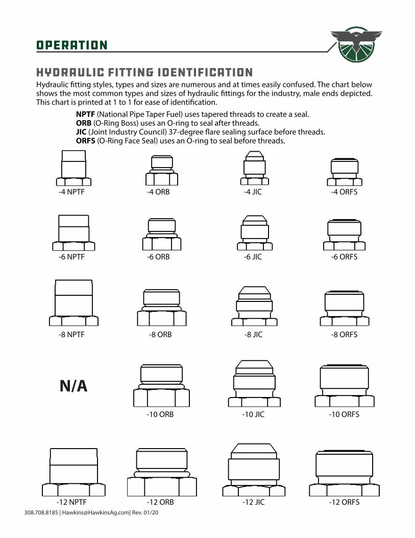
Hydraulic Fitting IdentificationHydraulic fitting styles, types and sizes are numerous and at times easily confused. The chart below shows the most common types and sizes of hydraulic fittings for the industry, male ends depicted. This chart is printed at 1 to 1 for ease of identification.
NPTF (National Pipe Taper Fuel) uses tapered threads to create a seal.ORB (O-Ring Boss) uses an O-ring to seal after threads.JIC (Joint Industry Council) 37-degree flare sealing surface before threads.ORFS (O-Ring Face Seal) uses an O-ring to seal before threads.
-4 NPTF
-6 NPTF
-8 NPTF
-12 NPTF
-4 ORB
-6 ORB
-8 ORB
-12 ORB
-10 ORB
-4 JIC
-6 JIC
-8 JIC
-12 JIC
-10 JIC
-4 ORFS
-6 ORFS
-8 ORFS
-12 ORFS
-10 ORFS
N/A
OPERATIONS
308.708.8185 | [email protected]| Rev. 09/20 1
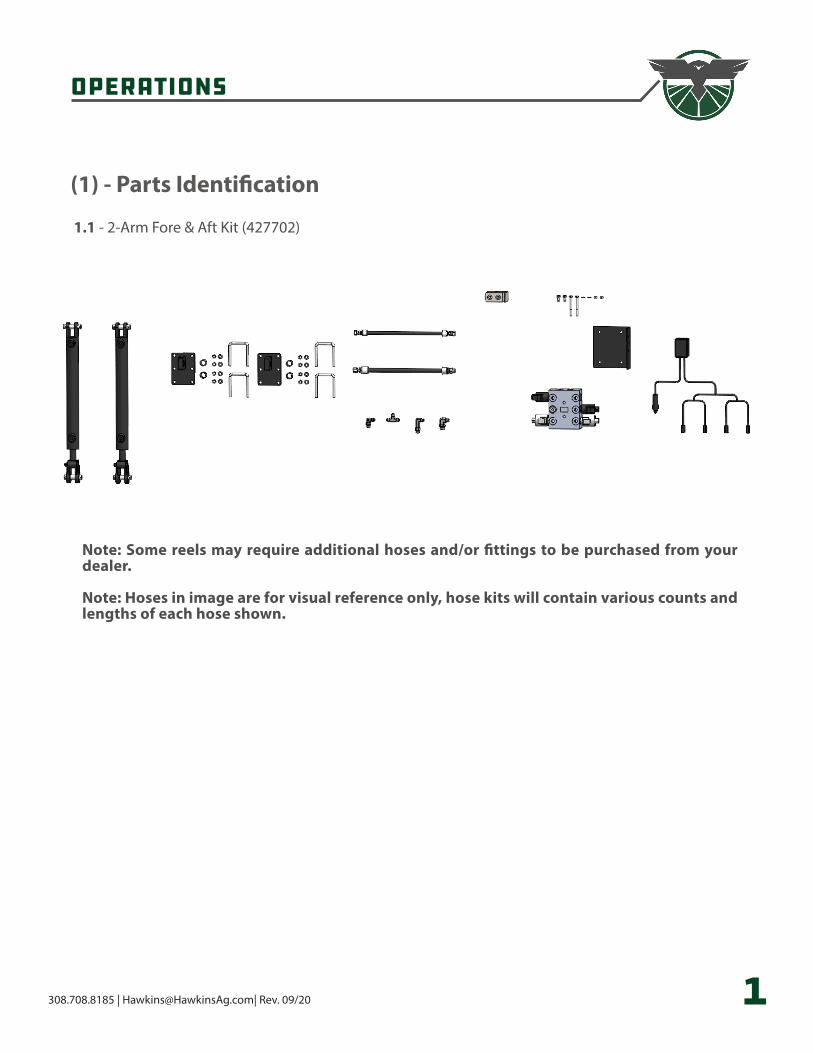
(1) - Parts Identification
1�1 - 2-Arm Fore & Aft Kit (427702)
Note: Some reels may require additional hoses and/or fittings to be purchased from your dealer�
Note: Hoses in image are for visual reference only, hose kits will contain various counts and lengths of each hose shown�
OPERATIONS
308.708.8185 | [email protected]| Rev. 09/20 2
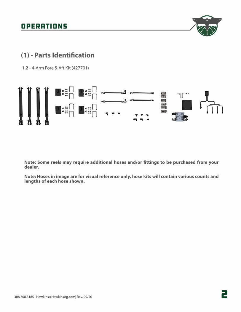
(1) - Parts Identification
1�2 - 4-Arm Fore & Aft Kit (427701)
Note: Some reels may require additional hoses and/or fittings to be purchased from your dealer�
Note: Hoses in image are for visual reference only, hose kits will contain various counts and lengths of each hose shown�
Operation
308.708.8185 | [email protected]| Rev. 09/20 3
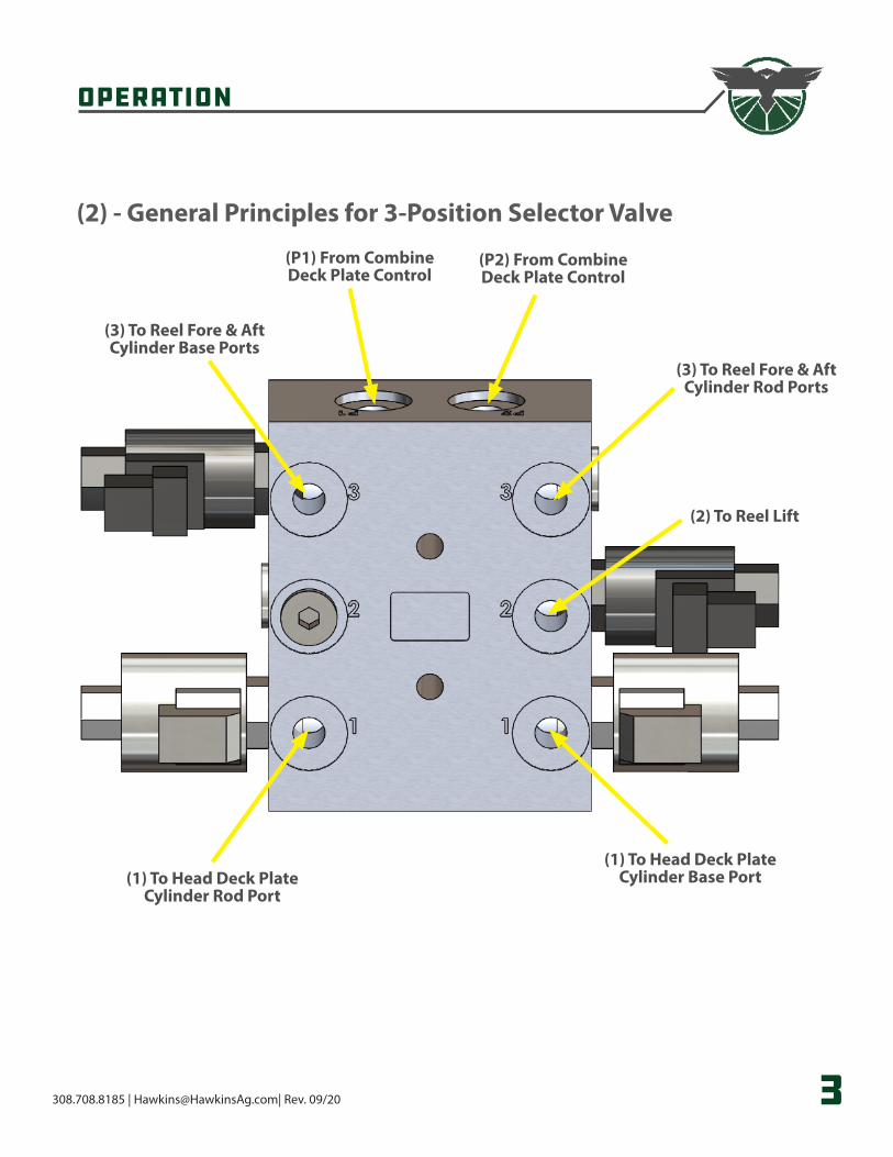
(2) - General Principles for 3-Position Selector Valve
(3) To Reel Fore & AftCylinder Base Ports
(P1) From CombineDeck Plate Control
(P2) From CombineDeck Plate Control
(3) To Reel Fore & AftCylinder Rod Ports
(2) To Reel Lift
(1) To Head Deck PlateCylinder Base Port(1) To Head Deck Plate
Cylinder Rod Port
Operation
308.708.8185 | [email protected]| Rev. 09/20 4
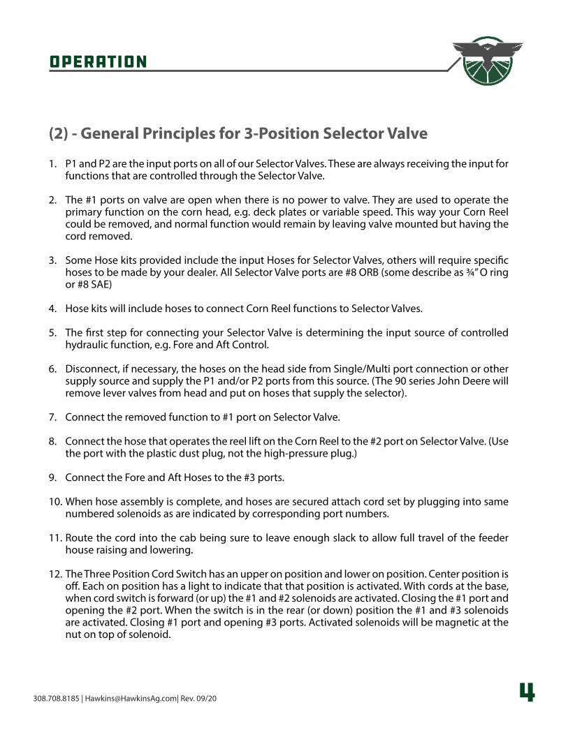
(2) - General Principles for 3-Position Selector Valve
1. P1 and P2 are the input ports on all of our Selector Valves. These are always receiving the input for functions that are controlled through the Selector Valve.
2. The #1 ports on valve are open when there is no power to valve. They are used to operate the primary function on the corn head, e.g. deck plates or variable speed. This way your Corn Reel could be removed, and normal function would remain by leaving valve mounted but having the cord removed.
3. Some Hose kits provided include the input Hoses for Selector Valves, others will require specific hoses to be made by your dealer. All Selector Valve ports are #8 ORB (some describe as ¾” O ring or #8 SAE)
4. Hose kits will include hoses to connect Corn Reel functions to Selector Valves.
5. The first step for connecting your Selector Valve is determining the input source of controlled hydraulic function, e.g. Fore and Aft Control.
6. Disconnect, if necessary, the hoses on the head side from Single/Multi port connection or other supply source and supply the P1 and/or P2 ports from this source. (The 90 series John Deere will remove lever valves from head and put on hoses that supply the selector).
7. Connect the removed function to #1 port on Selector Valve.
8. Connect the hose that operates the reel lift on the Corn Reel to the #2 port on Selector Valve. (Use the port with the plastic dust plug, not the high-pressure plug.)
9. Connect the Fore and Aft Hoses to the #3 ports.
10. When hose assembly is complete, and hoses are secured attach cord set by plugging into same numbered solenoids as are indicated by corresponding port numbers.
11. Route the cord into the cab being sure to leave enough slack to allow full travel of the feeder house raising and lowering.
12. The Three Position Cord Switch has an upper on position and lower on position. Center position is off. Each on position has a light to indicate that that position is activated. With cords at the base, when cord switch is forward (or up) the #1 and #2 solenoids are activated. Closing the #1 port and opening the #2 port. When the switch is in the rear (or down) position the #1 and #3 solenoids are activated. Closing #1 port and opening #3 ports. Activated solenoids will be magnetic at the nut on top of solenoid.
Operation
308.708.8185 | [email protected]| Rev. 09/20 5
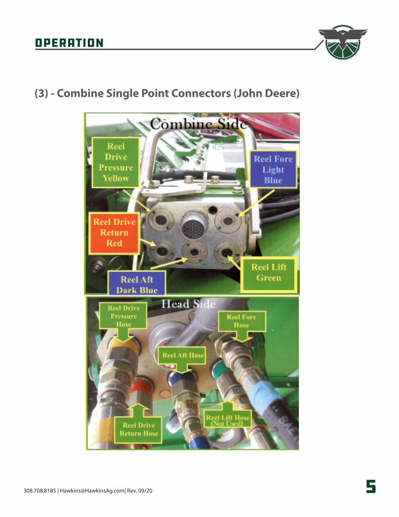
(3) - Combine Single Point Connectors (John Deere)
Operation
308.708.8185 | [email protected]| Rev. 09/20 6
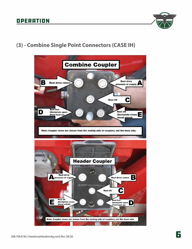
(3) - Combine Single Point Connectors (CASE IH)
Operation
308.708.8185 | [email protected]| Rev. 09/20 7
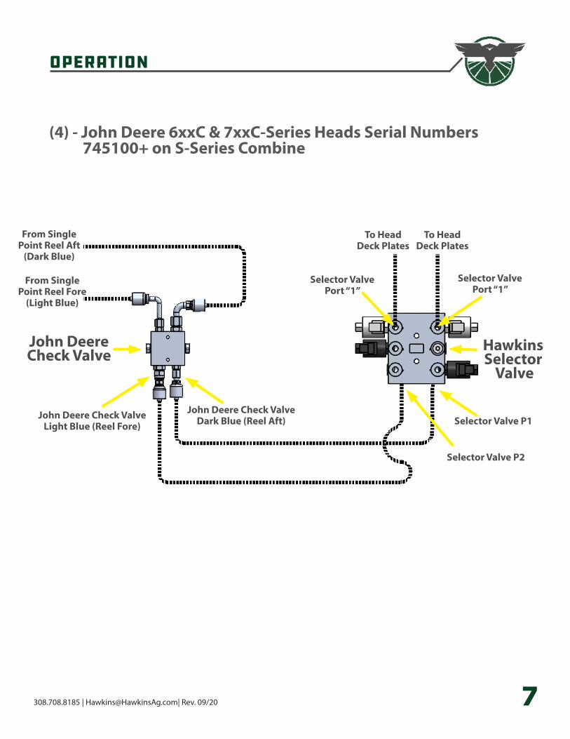
(4) - John Deere 6xxC & 7xxC-Series Heads Serial Numbers 745100+ on S-Series Combine
From SinglePoint Reel Aft
(Dark Blue)
From SinglePoint Reel Fore
(Light Blue)
John DeereCheck Valve
HawkinsSelector
Valve
John Deere Check ValveDark Blue (Reel Aft)John Deere Check Valve
Light Blue (Reel Fore) Selector Valve P1
Selector Valve P2
Selector ValvePort “1”
Selector ValvePort “1”
To Head Deck Plates
To Head Deck Plates
HawkinsSelector
Valve
Operation
308.708.8185 | [email protected]| Rev. 09/20 8
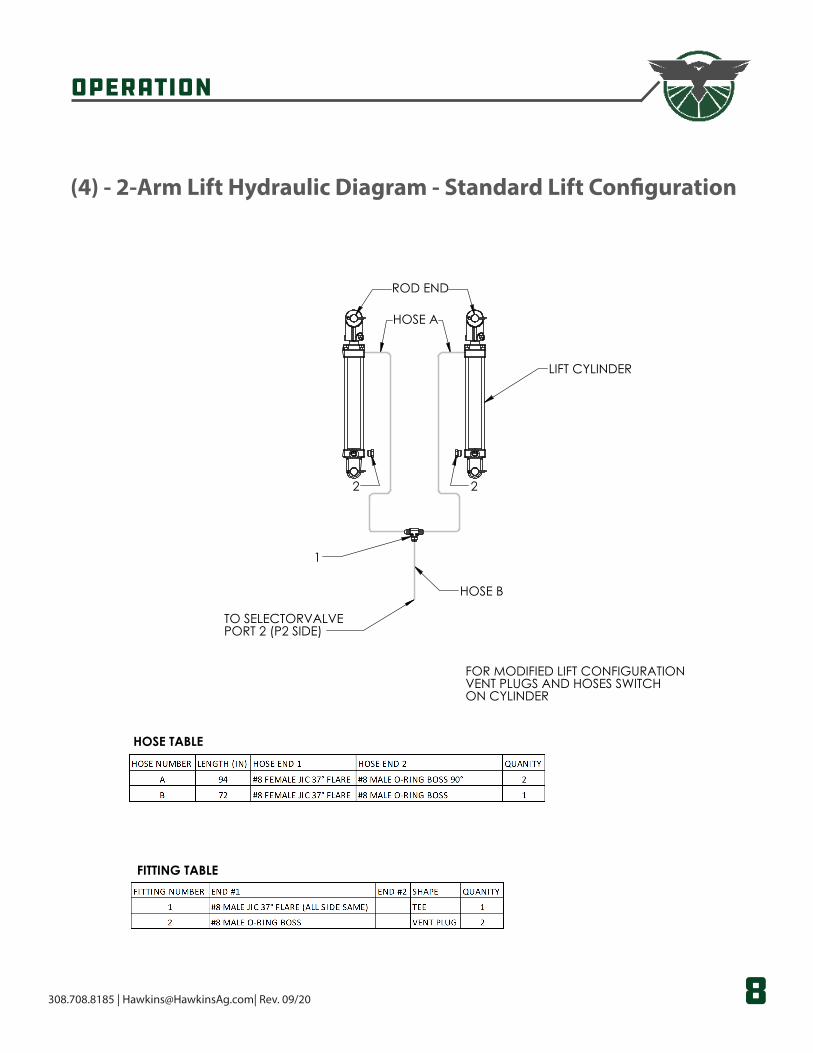
(4) - 2-Arm Lift Hydraulic Diagram - Standard Lift Configuration
HOSE A
TO SELECTORVALVEPORT 2 (P2 SIDE)
LIFT CYLINDER
ROD END
HOSE B
1
2 2
HOSE TABLE
FITTING TABLE
2 ARM LIFT HYDRAULIC DIAGRAMSTANDARD LIFT CONGIGURATION
FOR MODIFIED LIFT CONFIGURATIONVENT PLUGS AND HOSES SWITCHON CYLINDER
CORN REEL LIFT HYDRAULICS 2 ARMPART NUMBER
AGROdeviate
Operation
308.708.8185 | [email protected]| Rev. 09/20 9
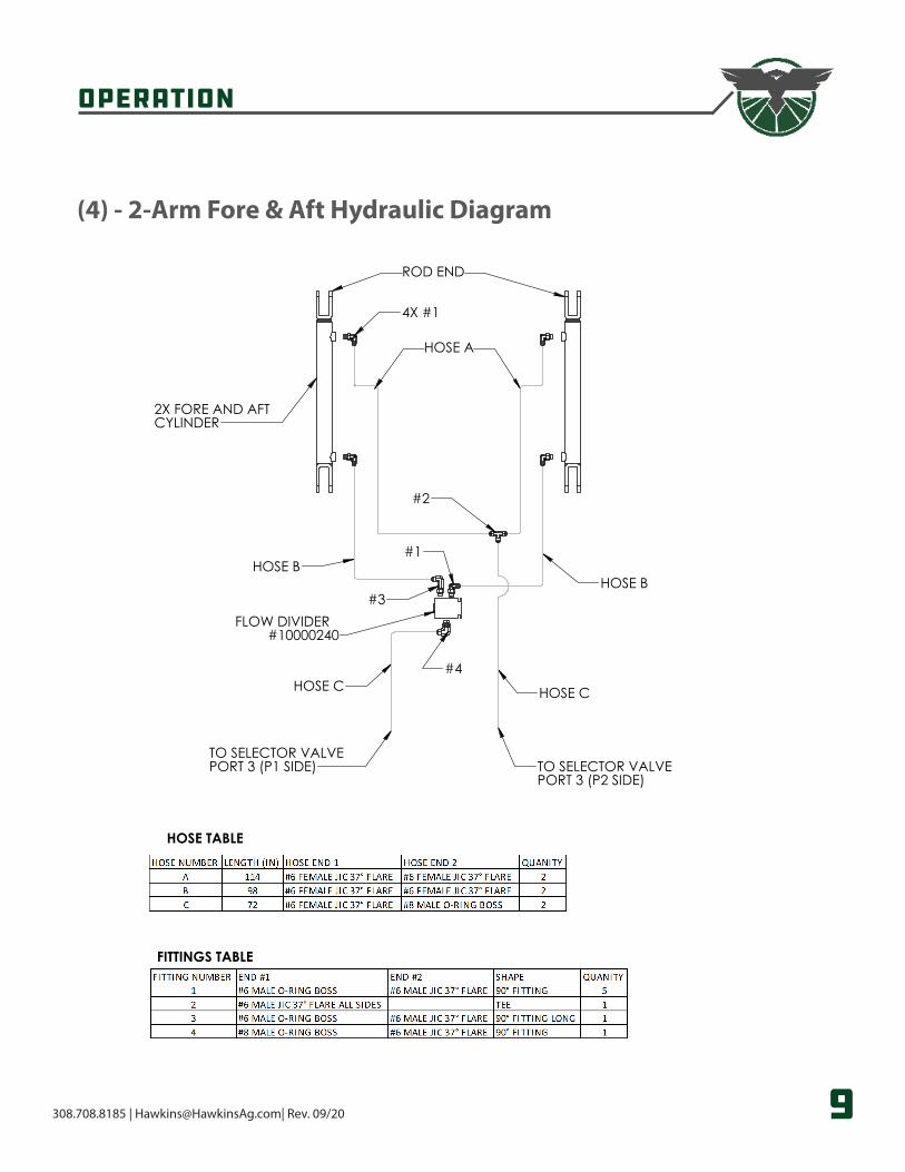
(4) - 2-Arm Fore & Aft Hydraulic Diagram
HOSE A
HOSE BHOSE B
HOSE C HOSE C
4X #1
#2
#1
#3
#4
2X FORE AND AFT CYLINDER
FLOW DIVIDER#10000240
TO SELECTOR VALVEPORT 3 (P1 SIDE) TO SELECTOR VALVE
PORT 3 (P2 SIDE)
ROD END
FITTINGS TABLE
HOSE TABLE
2 ARM FORE AND AFT HYDRAULIC DIAGRAM
2 ARM FORE AND AFTPART NUMBER AGROdeviate
Operation
308.708.8185 | [email protected]| Rev. 09/20 10
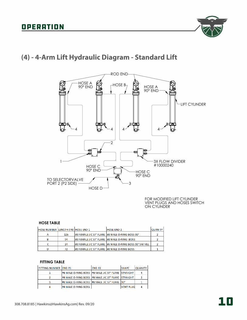
(4) - 4-Arm Lift Hydraulic Diagram - Standard Lift
HOSE A90° END HOSE A
90° ENDHOSE B
HOSE C90° END
HOSE C90° END
HOSE D
1
2
3
ROD END
3X FLOW DIVIDER#10000240
TO SELECTORVALVEPORT 2 (P2 SIDE)
LIFT CYLINDER
4 4 4 4
HOSE TABLE
FITTING TABLE
4 ARM LIFT HYDRAULIC DIAGRAMSTANDARD LIFT
FOR MODIFIED LIFT CYLINDERVENT PLUGS AND HOSES SWITCHON CYLINDER
CORN REEL LIFT HYDRAULICS 4 ARMPART NUMBER
AGROdeviate
Operation
308.708.8185 | [email protected]| Rev. 09/20 11
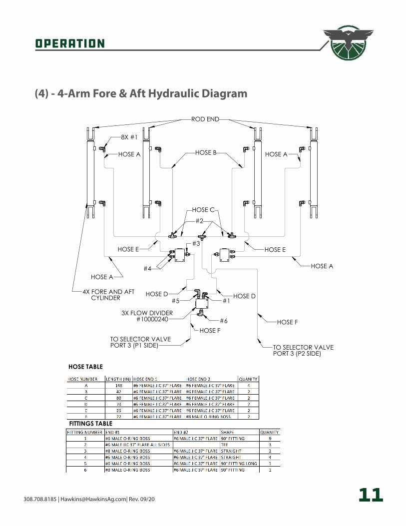
(4) - 4-Arm Fore & Aft Hydraulic Diagram
HOSE A HOSE A
HOSE C
ROD END
8X #1
HOSE A
HOSE A
HOSE EHOSE E
HOSE D HOSE D
HOSE FHOSE F
#3
#4
#5 #1
#6
#2
3X FLOW DIVIDER#10000240
4X FORE AND AFT CYLINDER
HOSE B
TO SELECTOR VALVEPORT 3 (P1 SIDE) TO SELECTOR VALVE
PORT 3 (P2 SIDE)
FITTINGS TABLE
HOSE TABLE
4 ARM FORE AND AFT HYDRAULIC DIAGRAM
4 ARM FORE AND AFTPART NUMBER AGROdeviate
Operation
308.708.8185 | [email protected]| Rev. 09/20 13
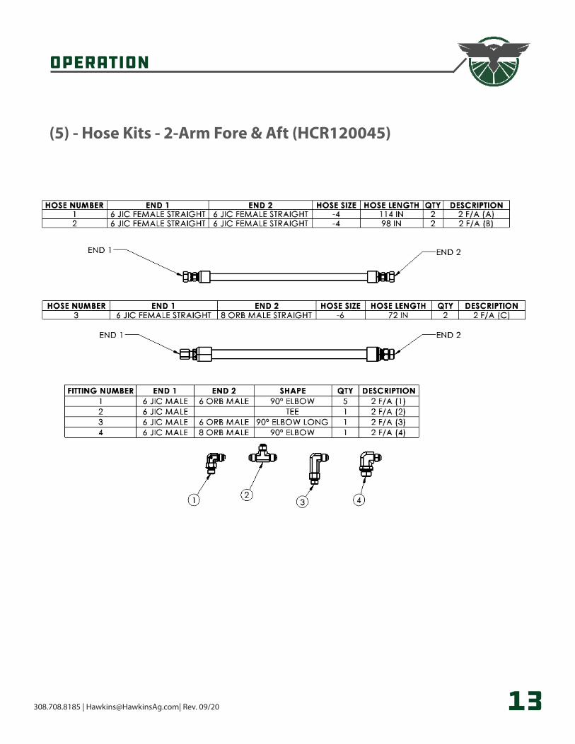
(5) - Hose Kits - 2-Arm Fore & Aft (HCR120045)
Operation
308.708.8185 | [email protected]| Rev. 09/20 14
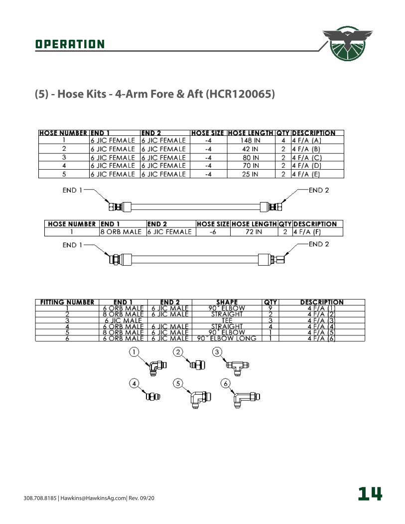
(5) - Hose Kits - 4-Arm Fore & Aft (HCR120065)
Operation
308.708.8185 | [email protected]| Rev. 09/20 15
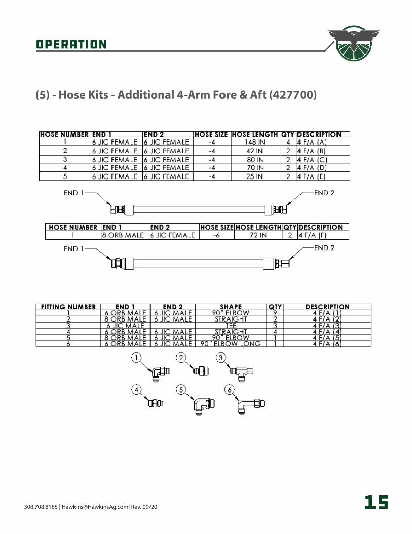
(5) - Hose Kits - Additional 4-Arm Fore & Aft (427700)
308.708.8185 | [email protected]| Rev. 09/20
308.708.8185 | HawkinsAg.com2120 4th AVE, Holdrege, NE 68949